JP6286924B2 - Container collection device - Google Patents
Container collection device Download PDFInfo
- Publication number
- JP6286924B2 JP6286924B2 JP2013169191A JP2013169191A JP6286924B2 JP 6286924 B2 JP6286924 B2 JP 6286924B2 JP 2013169191 A JP2013169191 A JP 2013169191A JP 2013169191 A JP2013169191 A JP 2013169191A JP 6286924 B2 JP6286924 B2 JP 6286924B2
- Authority
- JP
- Japan
- Prior art keywords
- container
- unit
- sorting
- transport
- volume
- Prior art date
- Legal status (The legal status is an assumption and is not a legal conclusion. Google has not performed a legal analysis and makes no representation as to the accuracy of the status listed.)
- Active
Links
Images


Classifications
-
- Y—GENERAL TAGGING OF NEW TECHNOLOGICAL DEVELOPMENTS; GENERAL TAGGING OF CROSS-SECTIONAL TECHNOLOGIES SPANNING OVER SEVERAL SECTIONS OF THE IPC; TECHNICAL SUBJECTS COVERED BY FORMER USPC CROSS-REFERENCE ART COLLECTIONS [XRACs] AND DIGESTS
- Y02—TECHNOLOGIES OR APPLICATIONS FOR MITIGATION OR ADAPTATION AGAINST CLIMATE CHANGE
- Y02W—CLIMATE CHANGE MITIGATION TECHNOLOGIES RELATED TO WASTEWATER TREATMENT OR WASTE MANAGEMENT
- Y02W30/00—Technologies for solid waste management
- Y02W30/50—Reuse, recycling or recovery technologies
- Y02W30/62—Plastics recycling; Rubber recycling
Description
本発明は、容器回収装置に関する。 The present invention relates to a container recovery apparatus.
飲料水などが収容されていた缶やペットボトル等の空容器を回収する容器回収装置が知られている(例えば、特許文献1参照)。 A container recovery device that recovers empty containers such as cans and plastic bottles that contain drinking water or the like is known (see, for example, Patent Document 1).
ところで、ペットボトルや缶などの空容器を分別した後、減容部などの圧潰手段などにより減容し、且つ、空きビンなどの減容困難な容器を減容することなく効率よく回収可能な小型の容器回収装置が望まれている。 By the way, after separating empty containers such as plastic bottles and cans, the volume can be reduced by a crushing means such as a volume reducing part, and an unrecoverable container such as an empty bottle can be efficiently recovered without reducing the volume. A small container recovery device is desired.
本発明は、上述した問題に鑑みてなされたもので、容器の種別に応じて容器を減容または非減容に仕分け、減容対象の容器を装置内の減容部にて減容したのち筐体内の回収箱にて回収し、非減容対象の容器を後段の起立容器搬送部にて搬送可能な搬送部を備えた小型の容器回収装置を提供すること、などを目的とする。 The present invention has been made in view of the above-described problems. After the containers are classified into volume-reduced or non-volume-reduced according to the type of the container, the volume to be reduced is reduced at the volume reducing unit in the apparatus. An object of the present invention is to provide a small container recovery device including a transport unit that can be recovered in a recovery box in a housing and can transport a non-volume-reduction target container in a subsequent standing container transport unit.
本発明の容器回収装置は、投入口から投入される容器を回収する容器回収装置であって、前記投入口より投入された容器を搬送する搬送部と、前記容器の種別を識別する識別部と、前記識別部の後段に設けられ、前記識別部により識別された前記容器を、搬入方向に対して左右方向、または、直進方向に仕分ける仕分け部と、前記仕分け部により前記直進方向に仕分けられた容器を起立させて搬送する起立容器搬送部と、前記仕分け部よりも搬送方向下流で、かつ前記起立容器搬送部よりも搬送方向上流に位置し、前記起立容器搬送部への搬送路を開放もしくは閉鎖する仕切板部と、前記仕分け部により前記搬入方向に対して左右方向に仕分けられた容器を減容する減容部と、前記減容部により減容された容器を収容する回収箱と、前記仕分け部および前記減容部の下方に設けられ、前記回収箱を収容する収容空間を有する回収箱収容部と、を備え、前記識別部の識別結果に基づいて、仕分け部が直進方向への仕分け処理を開始すると、前記仕切板部は前記起立容器搬送部への前記搬送路を開放状態にすることを特徴とする。 The container recovery device of the present invention is a container recovery device for recovering a container input from an input port, and includes a transport unit for transporting a container input from the input port, and an identification unit for identifying the type of the container The container that is provided in the subsequent stage of the identification unit and is identified by the identification unit is sorted in the straight direction by the sorting unit that sorts the container in the left-right direction or the straight direction with respect to the loading direction. An upright container transport unit that raises and transports the container , and is positioned downstream of the sorting unit in the transport direction and upstream of the upright container transport unit, and opens the transport path to the upright container transport unit or A partition plate part to be closed, a volume reducing part for reducing the volume of the container sorted by the sorting part in the left-right direction with respect to the loading direction, a recovery box for storing the container reduced by the volume reducing part, Said sorting Parts and provided under the volume reduction unit, and a collection box accommodating portion having an accommodating space for accommodating the collection box, on the basis of the identification result of the identifying portion, sorting processing of the sorting section to the straight direction When starting, the partition plate part opens the transport path to the upright container transport unit .
本発明によれば、容器の種別に応じて容器を減容または非減容に仕分け、減容対象の容器を装置内の減容部にて減容したのち筐体内の回収箱にて回収し、非減容対象の容器を後段の起立容器搬送部にて搬送可能な搬送部を備えた小型の容器回収装置を提供することができる。 According to the present invention, the container is classified into volume reduction or non-volume reduction according to the type of the container, and the volume to be reduced is reduced in the volume reduction unit in the apparatus and then collected in the collection box in the housing. In addition, it is possible to provide a small-sized container recovery device including a transport unit that can transport a non-volume-reduction target container in a subsequent standing container transport unit.
以下、本発明の一実施形態に係る容器回収装置Aの一例を、図面を参照しながら説明する。 Hereinafter, an example of a container recovery apparatus A according to an embodiment of the present invention will be described with reference to the drawings.
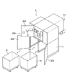
図1は本発明の実施形態に係る容器回収装置Aの一例を示す斜視図である。図1において容器回収装置Aの前面扉は閉状態である。図2は図1に示した容器回収装置Aの前面扉が開状態の一例を示す斜視図である。図3は本発明の実施形態に係る容器回収装置Aの一例を示す上面図である。図4は容器回収装置Aの一例を示す側面図である。 FIG. 1 is a perspective view showing an example of a container recovery apparatus A according to an embodiment of the present invention. In FIG. 1, the front door of the container recovery apparatus A is in a closed state. FIG. 2 is a perspective view showing an example of an open state of the front door of the container recovery apparatus A shown in FIG. FIG. 3 is a top view showing an example of the container recovery apparatus A according to the embodiment of the present invention. FIG. 4 is a side view showing an example of the container recovery apparatus A.
本発明の実施形態に係る容器回収装置Aは、投入口2から投入された容器aを搬送する搬送部(前部搬送部3,後部搬送部4)と、容器aの種別を識別する識別部7(種別検知部)と、識別部7の後段に設けられ、識別部7により識別された容器aを、搬入方向に対して左右方向、または、直進方向に仕分ける仕分け部8と、仕分け部8により直進方向に仕分けられた容器aを起立させて搬送する起立容器搬送部51と、仕分け部8により搬入方向に対して左右方向に仕分けられた容器aを減容する減容部10と、減容部10により減容された容器aを収容する回収箱41と、仕分け部8および減容部10の下方に設けられ、回収箱41を収容する収容空間を有する回収箱収容部42と、を備える。
The container recovery apparatus A according to the embodiment of the present invention includes a transport unit (a
容器としては、例えば、飲料水などの内容物を収容していた缶、ペットボトル、ビン等の容器aである。本実施形態では、容器回収装置Aは、回収時、内容物を取り出した空の容器を回収するものとする。尚、容器回収装置Aは、内容物を収容している容器aを回収した場合、例えば、投入口2から返却する、内容物の有無に応じた選別処理を行う、などの処理を行ってもよい。
減容対象の容器としては、缶、ペットボトルなどを挙げることができる。非減容対象の容器としては、ビンなどを挙げることができる。
Examples of the container include containers a such as cans, plastic bottles, and bottles that contain contents such as drinking water. In the present embodiment, it is assumed that the container collection device A collects an empty container from which the contents have been taken out during collection. In addition, when the container collection | recovery apparatus A collect | recovers the container a which accommodates the content, even if it performs processing, such as returning from the
Examples of containers for volume reduction include cans and plastic bottles. Examples of the non-volume-reducing container include bottles.
本発明の実施形態に係る容器回収装置Aは、図1、図2に示したように、筐体1(装置筐体)の前面に容器aの投入口2が開設されている。また、筐体1の前面部には、適正に回収された容器aに対して付与されるデポジット又は特典を表示したチケットなどを発行するプリンタ11が設けられていてもよい。
As shown in FIG. 1 and FIG. 2, the container collection device A according to the embodiment of the present invention has an
筐体1は前面に開閉扉200を有し、この開閉扉200は、投入口2が形成された上部前面開閉扉201と、上部前面開閉扉201の下部に設けられて回収箱41を収納自在とする下部開閉扉202と、を有する。筐体1は、下部開閉扉202内に、一つ又は複数の回収箱41を収容可能な回収箱収容部42を有する。この回収箱収容部42は、回収箱41を収容する収容空間であり、仕分け部8および減容部10の下方に設けられている。つまり、回収箱収容部42は、回収箱41を投入口2側(前面側)から収容自在に構成されている。
The
詳細には、筐体1内には、投入口2から投入された容器aを装置内に搬入する搬送部としての前部搬送部3(搬送路)および後部搬送部4、前部搬送部3で搬入された容器aをカメラ撮像位置(バーコード読み取り位置)に支持する転動支持手段5、前部搬送部3から転動支持手段5に容器aを載せ替えるために前部搬送部3を上下揺動させる上下移動手段6、転動支持手段で支持される容器aに表示(貼付)されたバーコード(種別)などを読み取るカメラ(識別部7)、バーコードカメラなどの識別部7による種別検知処理後、後部搬送部4上に搬送された容器aを、バーコードカメラなどの識別部7による識別結果に基づいて仕分ける仕分け部8(送り手段)、仕分け部8(送り手段)の初期位置における容器aの有無を検知する容器検出手段9(計量器:第一の容器検知手段、第2の計量部)、仕分け部8(送り手段)で仕分けられた容器aを減容処理する減容部10,10’、回収した容器aに対してデポジット又は特典のチケット等を発行するプリンタ11、などを有する。
Specifically, in the
前部搬送部3は、断面円形の無端状ベルト3aを、駆動プーリ3bと従動プーリ3cとに亘り所定間隔(筒状の容器aを二点で支持する間隔)をあけて2本平行に巻回したベルトコンベアで構成され、駆動プーリ3bはモータ3dの回転が動力伝達手段を介し伝達され、駆動回転されるように構成されている。
そして、搬送面を構成する無端状ベルト3aの表面は、後述する転動支持手段5を構成するローラの表面(アルミ材)における摩擦抵抗より大きい材質、例えば、ウレタン樹脂、或いは塩化ビニル樹脂等で構成されている。
また、その前部搬送部3は、筐体1内に架設した基台12上にロードセル13を介して支持した取付台14上に上下揺動可能に載置されている。
The
The surface of the
In addition, the
前部搬送部3の支持は、搬送始端側である駆動プーリ3bの軸端を取付台14上に起立した起立枠(不図示)で回動可能に支持し、前部搬送部3の機長方向の略中央位置が、取付台14上に設置した上下移動手段6で支持されている。
上下移動手段6は、上下動モータと、その上下動モータの出力軸に取り付けた偏心回転板と、偏心回転板と前部搬送部3を連結するアームとで構成され、モータが作動することでアームが揺動し、それにより前部搬送部3が搬送始端(駆動プーリ3b)側を支点として搬送終端(従動プーリ3c)側が上下される。尚、この上下移動手段6は、図示の構成に限定されず、搬送始端側を支点として反対側を上下し得る方法であれば何れの方式でもよい。
The
The vertical movement means 6 is composed of a vertical movement motor, an eccentric rotary plate attached to the output shaft of the vertical movement motor, and an arm that connects the eccentric rotary plate and the
また、前部搬送部3の始端側上部には容器aの投入を検出する容器検出用カメラ16(第二の容器検知手段)が設置されている。容器検出用カメラ16による撮像で容器aの投入の有無及び投入された容器aの搬送状態(位置)を判断する。この判断としては、撮像した画像の領域をマトリックス状に区分けし、その区分けされた領域毎に容器aの搬送状態(位置)などを識別する。
具体的には、容器aの長さ方向、高さ方向の各領域の画像を一定のしきい値により二値化して各領域の像の有無により判断する。そして、この容器検出用カメラ16の画像データの判断に基づいて前部搬送部3の駆動/停止が制御される。そして、容器検出用カメラ16は、前部搬送部3上の領域全てを撮像することができ、マトリックス状に区分けし、容器aの位置を検出することができるので、該マトリックス状のどの位置から容器aを検知したかを把握することができる。
つまり、上流方向から像が生じたと判断した場合には容器aの移動方向が順方向、即ち、投入口2から装置内へ容器aが移動したと判断することができる。逆に、下流方向から像が生じたと判断された場合には、容器aの移動方向が逆方向、即ち、装置内から投入口方向へ容器aが移動したと判断することができる。
また、容器検出用カメラ16による撮像を鮮明に行うために照明の光源17(LED)が配置されている。
In addition, a container detection camera 16 (second container detection means) that detects the introduction of the container a is installed at the upper part of the front end side of the
Specifically, the image of each region in the length direction and the height direction of the container a is binarized with a certain threshold value, and determination is made based on the presence or absence of an image in each region. The driving / stopping of the
That is, when it is determined that an image is generated from the upstream direction, it can be determined that the moving direction of the container a is the forward direction, that is, the container a has moved from the
In addition, an illumination light source 17 (LED) is arranged for clear imaging by the
転動支持手段5は、前部搬送部3を構成する無端状ベルト3aを挟んで左右両側に水平に配置した2本のローラ5a,5bと、その2本のローラ5a,5bを回転させるモータ(図示省略)と、そのモータの回転を2本のローラ5a,5bに伝達する動力伝達部材(図示省略)とで構成されている。尚、動力伝達部材は、2本のローラ5a,5bが同一方向に回転するように構成されている。
The rolling support means 5 includes two
また、この転動支持手段5のローラ5a,5bは、前部搬送部3の機長の中程位置から終端側手前位置までの長さを有しており、投入される缶及びペットボトル等の容器aの全長を安定よく支持し得るようになっている。尚、転動支持手段5を構成する2本のローラ5a,5bは、前部搬送部3による搬送時、2本のローラのうちの何れか1本が容器aと接触している。
そして、前部搬送部3が上下移動手段6によって前方下向きに傾斜下降されると、それまで無端状ベルト3aと2本のローラ5a,5bの片方の二点で支持されていた容器aは、無端状ベルト3aによる支持がなくなることで2本のローラ5a,5bによる二点支持に切り替わり、ローラの回転によって転動されることになる。
Further, the
And when the
カメラ(識別部7)は、投入された容器aを撮像するものであり、例えば、CCDカメラ、CMOSカメラなどであり、容器aの種別を識別する。また、カメラ(識別部7)は容器の周面に表示されているバーコードを読み取り、転動支持手段5の上方位置に、転動支持手段5の方向に向けて設置されている。
このカメラ(識別部7)は、筐体に所定角度に固定してもよいが、首振り回動式、スライド式等として、読み取り可能範囲を拡大するようにしてもよい。また、カメラ(識別部7)の台数は、1台に限らず、複数台でもよい。
このカメラ(識別部7)によるバーコードの読み取り処理は、カメラ(識別部7)にて容器aのバーコードが検知され、そのデータを、制御部のデータベースに格納されているデータと比較して処理される。例えば、容器aがペットボトルの場合、ペットボトルの色情報、ペットボトルの商品の名称、ペットボトルの空の重量値に対する基準重量値(空のボトルの重量よりも若干重い重量が設定され、飲み残しの有無の判断に利用される)、ボトルにより付与すべきデポジット額等が読み出される。
尚、デポジットシステムに対応する装置においては、仮に投入された容器aがデポジット対象でない容器aである場合、容器の回収は行うが、デポジットの付与を行わないようにすることも可能である。
The camera (identification unit 7) captures the charged container a, and is, for example, a CCD camera or a CMOS camera, and identifies the type of the container a. The camera (identification unit 7) reads a barcode displayed on the peripheral surface of the container and is installed at a position above the rolling support means 5 toward the rolling support means 5.
The camera (identification unit 7) may be fixed to the housing at a predetermined angle, but the readable range may be enlarged by a swinging type, a sliding type, or the like. Further, the number of cameras (identification unit 7) is not limited to one and may be a plurality.
In this barcode reading process by the camera (identification unit 7), the barcode of the container a is detected by the camera (identification unit 7), and the data is compared with the data stored in the database of the control unit. It is processed. For example, when the container a is a plastic bottle, the color information of the plastic bottle, the product name of the plastic bottle, the reference weight value for the empty weight value of the plastic bottle (a weight slightly heavier than the weight of the empty bottle is set, This is used to determine whether or not there is a remaining), and the deposit amount to be provided by the bottle is read out.
In addition, in the apparatus corresponding to a deposit system, when the container a put in is the container a that is not the deposit target, the container is collected, but it is also possible not to give the deposit.
カメラ(識別部7)による検知が完了すると、容器aは転動支持手段5から再び前部搬送部3に移載され、その前部搬送部3の駆動で後部搬送部4に供給され、該後部搬送部4の駆動で容器aは仕分け部8の初期位置に搬送される。
後部搬送部4は、前部搬送部3と同様、断面円形の無端状ベルト4aを、駆動プーリ4bと従動プーリ4cとに亘り所定間隔(筒状の容器aを二点で支持する間隔)をあけて2本平行に巻回したベルトコンベアで構成され、駆動プーリ4bはモータ4dの回転が動力伝達手段を介し伝達され、駆動回転されるように構成されている。
そして、搬送面を構成する無端状ベルト4aは、容器aを安定して搬送し得るように摩擦係数の大きい材質、例えば、ウレタン樹脂、或いは塩化ビニル樹脂等で構成されている。
When the detection by the camera (identification unit 7) is completed, the container a is transferred again from the rolling support means 5 to the
As with the
And the
また、後部搬送部4は、仕分け部8(送り手段)の初期位置における容器aの有無を検出する容器検出手段9(計量器:第一の容器検知手段、第2の計量部)を介して支持されている。即ち、後部搬送部4は、筐体1内に架設した基台12上に、容器検出手段9(計量器:第一の容器検知手段、第2の計量部)を介して支持した取付台14上に載置されている。
これにより、仕分け部8の初期位置(後部搬送部4が容器aを載承支持する位置)における該仕分け部8の仕分け位置から初期位置へ移動した時の重量変化を検出でき、容器検出手段9(計量器:第一の容器検知手段、第2の計量部)の計量値に変化(仕分け部8の動作前における計量値>仕分け部8の動作後の計量値)があれば、容器aは正しく仕分け回収されたと判断でき、逆に仕分け部8の動作前後における容器検出手段9の計量値に変化がなければ、容器aは正しく仕分け回収されず、不正行為が行われたものと判断される。
Further, the rear transport unit 4 is connected via a container detection unit 9 (measuring instrument: first container detection unit, second measurement unit) that detects the presence or absence of the container a at the initial position of the sorting unit 8 (feeding unit). It is supported. That is, the rear transport unit 4 is mounted on a base 12 installed in the
As a result, the weight change when the sorting unit 8 moves from the sorting position to the initial position at the initial position of the sorting unit 8 (the position where the rear transport unit 4 supports and supports the container a) can be detected. If there is a change (measured value before operation of the sorting unit 8> measured value after operation of the sorting unit 8) in the measured value of (metering device: first container detection means, second weighing unit), the container a is If it can be determined that the sorting / collection has been correctly performed, and if the measurement value of the container detection means 9 before and after the operation of the sorting unit 8 does not change, it is determined that the container a has not been correctly sorted / collected and an illegal act has been performed. .
仕分け部8(送り手段)は、識別部7により識別された容器aを、搬入方向に対して左右方向、または、直進方向に仕分ける。
詳細には、仕分け部8(送り手段)は、金属板或いは樹脂板等によって前後面(後部搬送部4で搬送される容器aの前後面と対応する面)及び下面(後部搬送部4で搬送される容器aの下半部外周面と対応する面)が開放され、後部搬送部4に載承支持される容器aを挟むよう対向する一対の壁部を有する断面略門型の振分け枠8aと、その振分け枠8aを左右方向に揺動させる揺動機構8bとで構成され、後部搬送部4の直上に位置し、後部搬送部4の機長方向略全ての範囲を覆い左右方向に揺動可能に支持されている。
左右方向への揺動は、後部搬送部4上に支持されている容器aを、カメラ(識別部7)の検知情報に基づいて後部搬送部4の左右両側に配置した減容部10,10’に振り分けるもので、筐体1内に垂下固着した取付板に振分け枠8aの長手方向の先端側上部中央が軸で揺動可能に軸支されている。
The sorting unit 8 (feeding unit) sorts the containers a identified by the identifying
Specifically, the sorting unit 8 (feeding means) is transported by a metal plate or a resin plate or the like (front and rear surfaces corresponding to the front and rear surfaces of the container a transported by the rear transport unit 4) and lower surface (transported by the rear transport unit 4). The surface of the container a corresponding to the outer peripheral surface of the lower half of the container a) is opened, and has a substantially gate-shaped
The swinging in the left-right direction is performed by
揺動機構8bは、カムなどの揺動手段と、その揺動手段を駆動するモータ22とで構成されている。そして、振分け枠8aは揺動機構8bによって後部搬送部4上に略垂直状態で垂下する初期位置から、カメラ(識別部7)の検知情報に基づいて左方向又は右方向の仕分け位置に揺動される。
振分け枠8aの揺動位置の検出は、振分け枠8aの初期位置を検出する仕分けセンサが固定フレームに取り付けられ、フラグ(不図示)が振分け枠8aの軸(不図示)に固着されている。
The swing mechanism 8b is composed of swing means such as a cam and a
For detecting the swing position of the
仕分け部8の振分け枠8aにより仕分けられた容器aを減容化する減容部10,10’が、仕分け部8の下方または前部搬送部3の下方に配置されている。
減容部10,10’は、仕分け部8で仕分けられた容器aを減容化するもので、2個の歯付きドラム10a,10bと、容器aを歯付きドラム10a,10bに押し込む回転羽根10cと、振分け枠8aで振り分けられた容器aを歯付きドラム10a,10bに案内するホッパー10dと、を有する。左右の減容部10,10’は1個のモータ(図示省略)で駆動するように構成されている。
ホッパー10dは金属材又は樹脂材によって樋状に形成され、そのホッパー10dが後部搬送部4を挟む左右両側位置に平行、且つ長さ方向の後端側(筐体1の投入口と対向する端部)を下向きに傾斜させて配置され、そのホッパー10dの案内方向先端部に回転羽根10cが配置されている。それにより、振分け枠8aで仕分け位置に振り分けられた容器aはホッパー10dを通り回転羽根10cで歯付きドラム10a,10b間に押し込まれ、小片状に破砕される。尚、この減容部10,10’は、図示の形態に限定されず、例えば、2本のローラの間に容器aを通して扁平状に潰すようなもの等、適宜選択し得るものである。
The
The
仕分け部8は、図4,図5(a),図5(b)に示すように、仕切板部81を有する。この仕切板部81は、識別部7による識別結果を示す信号に基づいて、容器aが第1の種別(缶やペットボトルなどの減容対象)の場合に、後段の起立容器搬送部51への搬送路を閉鎖し、容器aが第1の種別(減容対象)と異なる第2の種別(ビンなどの非減容対象)の場合に、起立容器搬送部51への搬送路を開放するように構成されている。
As shown in FIGS. 4, 5 (a), and 5 (b), the sorting unit 8 includes a
減容部10,10’で小片状に破砕減容化された容器aは、その減容部10,10’の下方に配置されている回収箱41に収容される。回収箱41は、筐体1の側面或いは前面に設けた下部開閉扉202を開けて出し入れされる。
The container a that has been crushed and reduced into small pieces by the
また、仕分け部8は、容器aが第1の種別(減容対象)の場合に、付勢力により仕切板部81を閉鎖状態とする付勢手段(モータなど)を有し、容器aが第2の種別の場合に、付勢手段による閉鎖状態の仕切板部81への付勢力の印加を抑止して、仕切板部81を開放自在としてもよい。
また、仕分け部8は、仕切板部81の閉鎖時、容器aにより所定値以上の力が仕切板部81に加えられた場合に、仕切板部81が開放状態となるように構成されていてもよい。
仕切板部81は、詳細には、図5(a)、図5(b)に示したように、仕切板固定ケース81cなどに、軸81bを回転中心として回転自在に固定されている。仕分け部8は、仕切板用モータ81mを有し、仕切板用モータ81mによりベルトなどを介して軸81bを回転駆動することで、仕切板部81の開放状態および閉鎖状態を制御可能に構成されている。この仕切板用モータ81mは後述の制御部により制御される。
In addition, the sorting unit 8 includes biasing means (such as a motor) that closes the
The sorting unit 8 is configured such that when the
Specifically, as shown in FIGS. 5A and 5B, the
図5に示したように、起立容器搬送部51は、回転軸51eの周囲に一つ又は複数の仕切り羽根51hが放射状に設けられ、その仕切り羽根51h相互間に容器aを収容する領域を有する回転体51bと、その回転体51bの回転により仕切り羽根51h相互間の領域に収容された容器aを、その回転体51bの回転方向適所に設けた投入位置から排出位置に移送する際、容器aを回転体51bの中心側へ弾性的に押圧付勢する空容器押さえ手段51fと、を有する。
As shown in FIG. 5, the standing
仕切板部81を介して容器a(ビンなどの非減容対象)が起立容器搬送部51に搬送された場合、容器aが傾斜部51aに沿って移動しながら起立した状態となり、その回転体51bの仕切り羽根51h相互間の領域に収容される。そして、容器aが空容器押さえ手段51fにより回転体51bの中心側へ弾性的に押圧付勢されながら、回転体51bの回転により後段に移動され、ベルトコンベア51cなどの搬送手段により後段へ移動するように構成されている。
回転体51bの回転軸の周囲に設けられる仕切り羽根51hの数は複数枚、例えば、円周を6等分する位置に仕切り羽根51hを設けて容器aを収容する領域を6個形成する、或いは容器を収容する領域を5個形成する等、その仕切り羽根51hの枚数、収容領域の個数は限定されない。
また、仕切り羽根51h相互で区画される収容領域の大きさは限定されないが、容器回収装置Aで回収する対象容器の最大容器に合わせて設定するのが好適である。
When the container a (a non-volume reduction target such as a bottle) is transported to the standing
The number of partition blades 51h provided around the rotation shaft of the
Moreover, although the magnitude | size of the storage area divided by the partition blade | wing 51h is not limited, It is suitable to set according to the largest container of the object container collect | recovered with the container collection | recovery apparatus A.
このように、容器aを空容器押さえ手段51fにより回転体51bの中心側へ押圧付勢しながら、回転体51bにより、ベルトコンベア51cなどに移動させるので、ビンなどの容器aを容易に起立させた状態でベルトコンベア51cにより移動させることができる。
As described above, the container a is moved to the
図6は、容器回収装置Aの電気的な構成の一例を示すブロック図である。
図6に示したように、容器回収装置Aは、各ブロックを制御するCPU25(制御部)にバス26などの通信路を介してROM27、RAM28、表示部29、キー操作部30、ロードセル13(第1の計量部)、プリンタ11、容器検出手段9(計量器:第一の容器検知手段、第2の計量部)、通信部31、インターフェース32が接続され、インターフェース32には容器検出用カメラ(第二の容器検知手段)16、カメラ(識別部7)、光源17(LED)、仕分けセンサ(1)23a、仕分けセンサ(2)23b、前部搬送部駆動用モータ3d、容器回転用ローラモータ5m(転動支持手段駆動用モータ)、上下動モータ6a、後部搬送部駆動用モータ4d、仕分けモータ22、減容用モータ10m、仕切板用モータ81m、などが接続されている。
FIG. 6 is a block diagram illustrating an example of an electrical configuration of the container recovery apparatus A.
As shown in FIG. 6, the container collection apparatus A has a CPU 25 (control unit) that controls each block via a communication path such as a
ROM27には、CPU25が実行する各種プログラムが記憶されている。制御部としてのCPU25は、プログラムを実行することにより、コンピュータとしての空容器回収装置に本発明に係る機能を実現する。
RAM28は、CPU25が実行するためのデータなどを一時記憶するもので、容器aの材質(アルミ缶、スチール缶、ペットボトル、ビン等)、飲料メーカー、商品の種類などの商品ファイルを記憶している。
The
The
キー操作部30は、各種情報等を入力するためのタッチキー、或いはキー入力のためのテンキー等を備え、表示部29は液晶表示器等で構成され、キー操作部30を操作して入力された情報、処理内容等が表示されるように構成されている。
プリンタ11は、本装置に投入された容器aのうち、デポジット対象の容器aを持ち込んだ提供者に容器回収のチケットを発行するものである。提供者はこのチケットを所定のお店等に持っていくことで、所定の対価の金額、或いは商品と交換することができる。また、回収した容器aの材質(アルミ缶、スチール缶、ペットボトル等)、飲料メーカー、商品種類、数量等のデータは、全てケース内のデータ処理装置(図示省略)に記憶し、その集計データは随時取り出せるようになっている。
The
The
ロードセル13(第1の計量部)は、前部搬送部3上の容器aの質量を計量し、計量値を示す信号をCPU25に出力する。
The load cell 13 (first measuring unit) measures the mass of the container a on the
容器検出手段9(計量器:第一の容器検知手段、第2の計量部)は、ロードセルなどにより構成され、後部搬送部4上の容器aの質量や、後部搬送部4上に容器aが存在するか否かを示す信号をCPU25に出力する。
The container detection means 9 (measuring device: first container detection means, second weighing unit) is configured by a load cell or the like, and the mass of the container a on the rear conveyance unit 4 or the container a on the rear conveyance unit 4 A signal indicating whether or not it exists is output to the
通信部31は、CPU25の制御により、管理用コンピュータなどと有線通信路または無線通信路を介してデータ通信を行う。
The
容器検出用カメラ16(第二の容器検知手段)は、前部搬送部3の始端側上部に設置され、容器aの投入を検出し、検出信号をCPU25に出力する。
The container detection camera 16 (second container detection means) is installed in the upper part of the start end side of the
カメラ(識別部7)は、投入された容器aを撮像し、容器aの種別を識別する。カメラ(識別部7)により撮像された画像に基づいてCPU25が容器aの種別を識別してもよい。
The camera (identification unit 7) images the charged container a and identifies the type of the container a. The
光源17(LED)は、容器検出用カメラ16の近傍に設けられ、容器検出用カメラ16による撮像を鮮明に行うために、容器aに光を照射する照明である。
The light source 17 (LED) is an illumination that is provided in the vicinity of the
仕分けセンサ(1)23a,仕分けセンサ(2)23bは、振分け枠8aの揺動位置を検出し、CPU25に出力する。
前部搬送部駆動用モータ3dは、CPU25の制御により、前部搬送部3を駆動する。
容器回転用ローラモータ5m(転動支持手段駆動用モータ)は、制御部の制御により、転動支持手段5の左右両側に水平に配置した2本のローラ5a,5bを回転・駆動させる。
The sorting sensor (1) 23a and the sorting sensor (2) 23b detect the swing position of the
The front transport
The container rotating roller motor 5m (rolling support means driving motor) rotates and drives the two
上下動モータ6aは、上下移動手段6において、前部搬送部3から転動支持手段5に容器aを載せ替えるために前部搬送部3を上下揺動させる駆動用モータである。
The vertical movement motor 6 a is a driving motor that causes the
仕分けモータ22は、CPU25の制御により、カムなどの揺動機構を駆動する。
The sorting
減容用モータ10mは、CPU25の制御により、仕分け部8で仕分けられた容器aを減容化するもので、2個の歯付きドラム10a,10bと、容器aを歯付きドラム10a,10bに押し込む回転羽根10cと、振分け枠8aで振り分けられた容器aを歯付きドラム10a,10bに案内するホッパー10dと、を有する。
The volume reduction motor 10m reduces the volume of the container a sorted by the sorting unit 8 under the control of the
仕切板用モータ81mは、CPU25の制御により、仕切板部81を移動・駆動することにより、仕切板部81の開放状態および閉鎖状態を制御する。
The
図7は、容器回収装置Aの動作の一例を示すフローチャートである。容器回収装置Aの動作の一例を、図7のフローチャートに基づいて説明する。尚、以下の説明は電源スイッチがONされ、各部がリセットされた状態で、容器aを減容対象や非減容対象、色(有色/無色)、原材料などで仕分ける例について説明する。 FIG. 7 is a flowchart showing an example of the operation of the container recovery apparatus A. An example of operation | movement of the container collection | recovery apparatus A is demonstrated based on the flowchart of FIG. In the following description, an example will be described in which the container a is sorted by volume reduction target, non-volume reduction target, color (colored / colorless), raw material, etc. in a state where the power switch is turned on and each part is reset.
ステップS1において、制御部としてのCPU25は、容器検出用カメラ(第二の容器検知手段)16により、投入口2に容器aが投入されたか否かを検知判断する。詳細には、CPU25は、容器aの投入の有無を画像の変化によって判別する。CPU25は、容器aの投入を検知した場合(YES)、ステップS2の処理に進み、それ以外の場合(NO)、検知動作を一定間隔で繰り返す。
In step S <b> 1, the
ステップS2において、CPU25は、容器検出手段9(計量器:第一の容器検知手段、第2の計量部)により、後部搬送部4上に容器aが存在するか否かを判別し、容器aが存在すると判別した場合(YES)、ステップS30の処理へ進み、容器aが存在しない場合(NO)、ステップS3の処理に進む。
容器aが存在する場合とは、今回の容器a投入より前に投入された容器aが前部搬送部3で後部搬送部4まで搬送され、仕分け部8の仕分け動作で仕分けられたにもかかわらず、不正行為などにより、仕分け部8の初期位置に容器aが存在する場合などが挙げられる。前部搬送部3に載承支持された容器aの重量がロードセル(第1の計量部)13で計量される。
In step S <b> 2, the
The case where the container a is present means that the container a introduced before the current container a is introduced is transported to the rear transport unit 4 by the
ステップS3において、CPU25は、前部搬送部3の駆動用モータ3dを駆動する。容器検出用カメラ16で撮像される画像データによる容器aの位置を示す座標データに基づいて、投入された容器aの先端(投入方向前側)が、転動支持手段5の略先端位置に位置したと判断されるまで、前部搬送部3の駆動用モータ3dを駆動する。
In step S <b> 3, the
ステップS4において、CPU25は、容器aの先端(投入方向前側)が、転動支持手段5の略先端位置に位置したと容器検出用カメラ16による撮像された画像データにより判断した場合、前部搬送部3の駆動を停止し、且つ、前部搬送部3を上下移動手段6の作動で下方に下げる。それにより、前部搬送部3で支持されていた容器aは、転動支持手段5の2本のローラ5a,5bに移載支持される(図3、図4参照)。
In step S4, when the
ステップS5において、CPU25は、転動支持手段5の2本のローラ5a,5bを駆動回転し、容器aを回転させる。
In step S5, the
ステップS6において、CPU25は、カメラ(識別部7)による撮像で、容器aの種別、例えば、減容対象、非減容対象などを識別する。詳細には、本実施形態では、CPU25は、カメラ(識別部7)により容器aの周面に貼付されたバーコードを検知し、バーコードの情報を読み出す。例えば、容器aの色情報、商品の名称、容器aの空の重量値に対する基準重量値等、容器aにより返却すべきデポジット額等を、RAM28やROM27などの記憶部から読み出す。「基準重量値」は、誤差等を考慮し、空のボトルの重量値より若干重い重量値が設定される。そして、この「基準重量値」は容器a内に内容物の残りがあるか否かの判断基準に使用される。
In step S <b> 6, the
ステップS7において、CPU25は、識別部7による識別の結果、容器aが第1の種別(減容対象:缶、ペットボトルなど)の場合、ステップS11の処理に進み、容器aが第2の種別(非減容対象:ビンなど)の場合に、ステップS8の処理に進む。
In step S7, the
ステップS8において、CPU25は、第2の種別(非減容対象:ビンなど)の場合に、仕分け部8の仕切板部81を、起立容器搬送部51への搬送路を開放するように制御する。
In step S <b> 8, the
ステップS9において、CPU25は、前部搬送部3,後部搬送部4を駆動して、容器aを、仕分け部8よりも後段の起立容器搬送部51へ搬送する。
In step S <b> 9, the
ステップS10において、CPU25は、起立容器搬送部51を駆動して、ビンなどの容器aを後段のベルトコンベア51cなどの搬送手段へ移動させて、ステップS22の処理に進む。詳細には、CPU25は、容器aが起立容器搬送部51の傾斜部51aに沿って移動しながら起立した状態となり、回転体51bの仕切り羽根51h相互間の領域に収容された場合、回転体51bを所定方向に回転させることで、容器aを後段のベルトコンベア51cなどの搬送手段へ移動させる。その搬送手段により搬送される容器aは、24本などの所定個数収容可能なケースなどに収容される。
In step S10, the
ステップS11において、CPU25は、識別部7による識別の結果(S7)、容器aが第1の種別(減容対象:缶、ペットボトルなど)の場合、仕切板部81を、起立容器搬送部51への搬送路を閉鎖するように駆動・制御する。
In step S <b> 11, when the result of identification by the identification unit 7 (S <b> 7) is that the container a is of the first type (volume reduction target: can, plastic bottle, etc.), the
ステップS12において、CPU25は、カメラ(識別部7)による撮像で容器aの種別の検知が完了した後、転動支持手段5の駆動を停止し、上下移動手段6を作動して前部搬送部3を元の位置に上昇させ、容器aを転動支持手段5から前部搬送部3に移載し、容器aを搬送可能な状態にする。
In step S12, the
ステップS13において、CPU25は、前部搬送部3に載承した状態でロードセル(第1の計量部)13により計量した重量値が、ステップS6で読み出された空の容器aの基準重量値より重いか否かを判断する。ロードセル(第1の計量部)13の出力値が基準重量値より重い場合(YES)、つまり、投入された容器aの重量が基準重量値より重い場合、CPU25は、容器a内に飲み残しなどがあると判別してステップS14の処理に進み、ロードセル(第1の計量部)13の出力値が基準重量値より軽い場合(NO)、ステップS16の処理に進む。
In step S13, the
ステップS14において、CPU25は、前部搬送部3の駆動用モータ3dを逆回転駆動し、載承保持した容器aを投入口2に向けて搬送する。
In step S <b> 14, the
ステップS15において、CPU25は、容器aを投入口2側に戻した後、例えば、表示部29に「中身を捨ててから再度、投入して下さい」等のエラーメッセージを表示する処理を行う。
In step S <b> 15, after returning the container a to the
ステップS16において、CPU25は、前部搬送部3の駆動用モータ3d及び後部搬送部4の駆動用モータ4dを正回転駆動する。そして、容器検出用カメラ16からの画像データと、容器の位置を示す座標データに基づき、容器aの後端部(搬送方向後端側)が画像データから消えた後、所定の時間が経過するまで、前部搬送部3及び後部搬送部4を駆動する。つまり、前部搬送部3及び後部搬送部4が連続し隣接して配置されているので、前部搬送部3での画像データから容器aが消えて、ごく僅かな所定時間が経過した場合、容器aが確実に後部搬送部4へ乗り移っていることになる。容器aは後部搬送部4上の所定位置、即ち、初期位置に搬送支持される。
In step S <b> 16, the
ステップS17において、容器aが後部搬送部4上に位置されると、ステップS6で検出された容器aの種別情報、例えば容器aの色情報や材質などに基づき、仕分け部8の振分け枠8aを揺動機構によって初期位置から左右何れか一方の仕分け位置方向に揺動し、後部搬送部4上の容器aを仕分け位置(送り位置)に振り分ける。つまり、容器aの後端部(搬送方向後端側)が画像データから消えた後、所定の時間が経過すると、確実に容器aは、後部搬送部4上に位置しているので、後部搬送部4の駆動が停止した後、ごく僅かな所定の時間経過後に仕分け部8の仕分けモータを駆動することで、容器aを仕分けることができる。
In step S17, when the container a is positioned on the rear transport unit 4, the sorting
そして、この場合、容器aの後端部(搬送方向後端側)が画像データから消えて所定時間経過するまで、前部搬送部3及び後部搬送部4が駆動されるので、容器aの長さにより、後部搬送部4上における容器aの搬送方向の先頭位置は異なるが、振分け枠8aは後部搬送部4上の全ての領域を覆うように設けられているので、容器aの搬送方向の先頭がどの位置であっても、確実に容器aを振り分けることができる。
In this case, the
そして、例えば、容器aの材質や色などに応じて、後部搬送部4の右側または左側に仕分けられる。そして、振分け枠8aの揺動は、仕分けセンサ(1)23aと仕分けセンサ(2)23bの両方がフラグで遮られなくなる(仕分けセンサ(1)23a、仕分けセンサ(2)23b:OFF)まで駆動される。
Then, for example, according to the material or color of the container a, the rear transfer unit 4 is sorted to the right side or the left side. The swing of the
ステップS18において、仕分けセンサ(1)23aと仕分けセンサ(2)23bの両方がフラグで遮られなくなる(センサ:OFF)を検知する。これにより、CPU25は、仕分け部8の振分け枠8aが初期位置から仕分け位置に移動したことを確認することができる。
In step S18, it is detected that both the sorting sensor (1) 23a and the sorting sensor (2) 23b are not blocked by the flag (sensor: OFF). Thus, the
ステップS19において、CPU25は、仕分け部8の振分け枠8aを、揺動機構8bの逆方向駆動によって仕分け位置から初期位置に戻す。振分け枠8aの揺動は、仕分けセンサ(1)23aと仕分けセンサ(2)23bの両方がフラグで遮られるまで駆動する。
In step S19, the
ステップS20において、CPU25は、仕分けセンサ(1)23aと仕分けセンサ(2)23bの両方がフラグで遮られる(センサ:ON)を検知する。これにより、CPU25は、仕分け部8の振分け枠8aが仕分け位置から初期位置に移動したことを確認することができる。
In step S20, the
ステップS21において、CPU25は、容器検出手段9(計量器:第一の容器検知手段、第2の計量部)により、後部搬送部4上に容器aが存在するか否かを判断する。容器aが後部搬送部4上に存在する場合(YES)、ステップS30の処理に進み、容器aが存在しない場合(NO)、ステップS22の処理に進む。
In step S <b> 21, the
容器検出手段9(計量器:第一の容器検知手段、第2の計量部)による容器aの有無の検出は、仕分け部8の動作(S17〜S20)後の検出であるから、通常はステップS17からステップS20の過程で容器aは所定の方向に仕分けられ、ステップS20で振分け枠8aが初期位置に戻った時、容器aは既に仕分けられた後なので、容器検出手段9(計量器:第一の容器検知手段、第2の計量部)から出力される重量値が、後部搬送部4上に容器aが載っている重量値を出力することはない。
Since the detection of the presence or absence of the container a by the container detection means 9 (meter: first container detection means, second measurement unit) is detection after the operation of the sorting unit 8 (S17 to S20), it is usually a step. In the process from S17 to step S20, the container a is sorted in a predetermined direction. When the
しかし、例えば、容器aに紐等を結び、その紐を手で持ち、容器aを投入口2から投入し、ステップS20で振分け枠8aが仕分け位置から初期位置に戻る瞬間に該容器aに結んだ紐を引き戻すことで、仕分け位置に振り分けられた容器aは後部搬送部4上(初期位置)に引き戻される。この操作を繰り返すことで、1個の容器aで、何回もデポジットや特典を取得する不正行為が可能となる。そこで、仕分け部8の振分け枠8aが左右何れかの仕分け位置に回動して容器aを仕分けた後、該振分け枠8aが仕分け位置から初期位置の戻った時の容器検出手段9(計量器:第一の容器検知手段、第2の計量部計)の出力を判断することで、正常に仕分けされたか否かを判断することができる。
即ち、上記不正行為により投入された容器aが後部搬送部4上(初期位置)に引き戻された場合、容器検出手段9(計量器:第一の容器検知手段、第2の計量部)の出力(重量値)が、重量値「大」(容器有り)→重量値「小」(容器無し)→重量値「大」(容器有り)と変化し、不正の疑いがあると推測できる。尚、正常に仕分けられた場合、容器検出手段9(計量器:第一の容器検知手段、第2の計量部)の出力(重量値)は、重量値「大」(容器有り)→重量値「小」(容器無し)→重量値「小」(容器無し)と変化する。
However, for example, a string or the like is tied to the container a, the string is held by hand, the container a is inserted from the
That is, when the container a thrown in by the above fraudulent action is pulled back onto the rear transport section 4 (initial position), the output of the container detection means 9 (metering device: first container detection means, second weighing section) (Weight value) changes from weight value “large” (with container) → weight value “small” (without container) → weight value “large” (with container), and it can be assumed that there is a suspicion of fraud. In the case of normal sorting, the output (weight value) of the container detection means 9 (meter: first container detection means, second measurement unit) is weight value “large” (with container) → weight value. “Small” (no container) → Weight value “small” (no container).
このように、容器検出手段9(計量器:第一の容器検知手段、第2の計量部)で容器aがあるか否かを判断する場合、通常、例えばロードセル式の計量器で物の重さを判断する場合、物を計量部に載せた場合、出力される重量値が安定するまでには一定の時間がかかる。
しかし、本発明の計量器(第一の容器検知手段)では、容器aの正確な重量を計量する必要はないので、容器aが仕分けられ、計量器から出力される重量値がゼロになり、その後に、不正により容器aが戻された場合、容器aが計量器に載ることで、計量器から一定の重量でないにしろ重量が出力されるようになる、このような状態を把握することで、仕分けられた後に、容器aが検知されたと判断することが可能になる。
As described above, when determining whether or not the container a is present by the container detection means 9 (the weighing instrument: the first container detection means, the second weighing unit), the weight of the object is usually measured by, for example, a load cell type weighing instrument. When determining the thickness, when an object is placed on the measuring unit, it takes a certain time until the output weight value is stabilized.
However, in the measuring instrument (first container detecting means) of the present invention, since it is not necessary to measure the exact weight of the container a, the container a is sorted, and the weight value output from the measuring instrument becomes zero, After that, when the container a is returned due to fraud, the weight of the container a is output from the measuring instrument, if it is not a constant weight. After sorting, it becomes possible to determine that the container a has been detected.
ステップS22において、CPU25は、ステップS6で識別された種別情報、例えば、容器aのバーコードなどから読み出されたデポジット額を付与し、その金額と日時データ、及びステップS6で読み出したバーコード情報、商品名等をRAM28に記憶する。
In step S22, the
ステップS23において、CPU25は、ステップS22で付与されたデポジット額を、プリンタ11によりチケットに印字・発行する。
例えば、チケットを取得したボトル提供者は、そのチケットを店員のいるレジに持っていき、差し出すことで、そのデポジット額の金額を受け取ることができる。
In step S23, the
For example, the bottle provider who has acquired the ticket can take the ticket to the cash register where the store clerk is present and submit it to receive the amount of the deposit.
ステップS30において、CPU25は、ステップS21で仕分け部8の振分け枠8aが仕分け位置から初期位置に戻った時の容器検出手段9(計量器:第一の容器検知手段、第2の計量部)の出力(重量値)により、後部搬送部4上に容器aが載っていると判断され、不正の疑いがあるので、後部搬送部4及び前部搬送部3の駆動用モータを逆回転駆動して、後部搬送部4上の容器aを投入口2に戻し、容器回収装置Aから排出する。
In step S30, the
ステップS31において、CPU25は、表示部29に「店員をお呼び下さい。」等のエラーメッセージをエラー音と共に表示する。また、CPU25は、表示部29に「デポジット額は生成されなかった」旨の表示をしてもよい。
In step S31, the
上記フローチャートのステップS22で記憶されたデポジット額を付与した履歴情報は、例えば、店舗の営業終了時に上位の管理装置へ送信され管理するようにしてもよい。また、履歴情報は装置のRAM28内に記憶するようにしたが、上位の管理装置の記憶部に直接記憶し、管理するようにしてもよい。
The history information provided with the deposit amount stored in step S22 of the flowchart may be transmitted to and managed by a higher management device at the end of the store business, for example. The history information is stored in the
以上、説明したように、本発明の実施形態に係る容器回収装置Aは、投入口2から投入される容器aを搬送する搬送部(前部搬送部3、後部搬送部4)と、容器aの種別を識別する識別部7と、識別部7の後段に設けられ、識別部7により識別された容器aを、搬入方向に対して左右方向、または、直進方向に仕分ける仕分け部8と、仕分け部8により直進方向に仕分けられた容器a(非減容対象物など)を起立させて搬送する起立容器搬送部51と、仕分け部8により搬入方向に対して左右方向に仕分けられた容器a(減容対象物など)を減容する減容部10と、減容部10により減容された容器aを収容する回収箱41と、仕分け部8および減容部10の下方に設けられ、回収箱41を収容する収容空間を有する回収箱収容部42と、を有する。
このように、容器aの種別に基づいて、容器aを減容または非減容に仕分け、減容対象の容器aを装置内の減容部10にて減容したのち筐体1内の回収箱41にて回収し、非減容対象の容器aを後段の起立容器搬送部51にて搬送可能な小型の容器回収装置Aを提供することができる。
As described above, the container recovery apparatus A according to the embodiment of the present invention includes a transport unit (a
As described above, based on the type of the container a, the container a is sorted into volume reduction or non-volume reduction, and after the volume of the container a to be reduced is reduced by the
つまり、ペットボトルや缶などの容器aを分別した後、減容部10などの圧潰手段などにより減容し、且つ、空きビンなどの減容困難な容器aを減容することなく効率よく回収可能な小型の容器回収装置Aを提供することができる。
In other words, after separating containers a such as PET bottles and cans, the volume is reduced by a crushing means such as a
また、本発明の実施形態に係る容器回収装置Aは、回収箱41が、筐体1内の減容部10および仕分け部8の下方まで延設されている。このため、小型の容器回収装置Aを提供することができる。また、比較的小型の筐体1内に、比較的大きい容積の回収箱41を設けることができ、減容された容器aを比較的大量に回収箱41にて回収することができる。
Further, in the container collection device A according to the embodiment of the present invention, the
また、回収箱収容部42は、回収箱41を、投入口2側(筐体1の前面側)から収容自在に構成されているので、筐体1の前面側から回収箱41を容易に収容および取り出すことができる。
Further, since the collection
また、装置筐体(筐体1)は、投入口2が形成された上部前面開閉扉201と、上部前面開閉扉201の下部に設けられ、回収箱41を収納自在とする下部開閉扉202と、を有するので、下部開閉扉202のみを開状態とすることで(上部前面開閉扉201は閉状態)、回収箱41を容易に取り出すことができる。
また、投入口2や搬送部(前部搬送部3など)のメンテナンス時には、上部前面開閉扉201のみを開状態とすることで、下部開閉扉202を開状態とすることなく、容易にメンテナンスを行うことができる。
In addition, the apparatus housing (housing 1) includes an upper front opening /
In addition, during maintenance of the
また、本発明の実施形態に係る容器回収装置Aにおいて、識別部7による識別結果に基づいて容器aが第1の種別(減容対象など)の場合に、仕分け部8は、起立容器搬送部51への搬送路を閉鎖し、容器aが第1の種別と異なる第2の種別(非減容対象など)の場合に、起立容器搬送部51への搬送路を開放する仕切板部81を有する。
このように、仕切板部81は、容器aの種別に応じて開閉自在となっており、仕分け部8により確実に仕分けを行うことが可能な容器回収装置Aを提供することができる。
Moreover, in the container collection | recovery apparatus A which concerns on embodiment of this invention, when the container a is a 1st classification (volume reduction object etc.) based on the identification result by the
Thus, the
また、この仕切板部81は、通常時に閉状態となっており、外乱光の入光を防止することができ、識別部7により容器を高精度で識別することができる。
In addition, the
仕分け部8は、仕切板部81の閉鎖時、容器aにより所定値以上の力が仕切板部81に加えられた場合に、仕切板部81が開放状態となるように構成されている。
このため、仕切板部81が閉鎖時、例えば、いたずら目的などで、容器aが投入口2から投げ入れられた場合であっても、仕切板部81が開放状態となるので、仕切板部81の破損などを防止することができる。
The sorting unit 8 is configured such that when the
For this reason, even when the
また、仕分け部8は、容器aが第1の種別(減容対象など)の場合に、付勢力により仕切板部81を閉鎖状態とする付勢手段(モータやバネなど)を有し、容器aが第2の種別(非減容対象)の場合に、付勢手段による閉鎖状態の仕切板部81への付勢力の印加を抑止して、仕切板部81を開放自在としてもよい。
こうすることで、通常時、容器aが第1の種別(減容対象など)の場合に、付勢力により仕切板部81を閉鎖状態とし、容器aが第2の種別(ビンなどの非減容対象)の場合に、その容器aの質量と搬送部による搬送力とにより、仕切板部81を僅かな力で押圧することで開放状態とし、容器aを後段の起立容器搬送部51へ容易に搬送することができる。
In addition, the sorting unit 8 includes biasing means (such as a motor and a spring) that closes the
By doing so, when the container a is normally in the first type (volume reduction target, etc.), the
以上、本発明の実施形態について図面を参照して詳述してきたが、具体的な構成はこれらの実施形態に限られるものではなく、本発明の要旨を逸脱しない範囲の設計の変更等があっても本発明に含まれる。
また、上述の各図で示した実施形態は、その目的及び構成等に特に矛盾や問題がない限り、互いの記載内容を組み合わせることが可能である。
また、各図の記載内容はそれぞれ独立した実施形態になり得るものであり、本発明の実施形態は各図を組み合わせた一つの実施形態に限定されるものではない。
As described above, the embodiments of the present invention have been described in detail with reference to the drawings. However, the specific configuration is not limited to these embodiments, and there are design changes and the like without departing from the gist of the present invention. Is included in the present invention.
Further, the embodiments described in the above drawings can be combined with each other as long as there is no particular contradiction or problem in the purpose and configuration.
Moreover, the description content of each figure can become independent embodiment, respectively, and embodiment of this invention is not limited to one embodiment which combined each figure.
以上、本発明の実施形態について説明したが、本発明の実施形態の一部または全部は、以下の付記のように記載される。
[付記1]
投入口から投入される容器を回収する容器回収装置であって、
前記投入口より投入された容器を搬送する搬送部と、
前記容器の種別を識別する識別部と、
前記識別部の後段に設けられ、前記識別部により識別された前記容器を、搬入方向に対して左右方向、または、直進方向に仕分ける仕分け部と、
前記仕分け部により前記直進方向に仕分けられた容器を起立させて搬送する起立容器搬送部と、
前記仕分け部により前記搬入方向に対して左右方向に仕分けられた容器を減容する減容部と、
前記減容部により減容された容器を収容する回収箱と、
前記仕分け部および前記減容部の下方に設けられ、前記回収箱を収容する収容空間を有する回収箱収容部と、を備えることを特徴とする
容器回収装置。
[付記2]
前記回収箱は、前記仕分け部および前記減容部の下方まで延設されていることを特徴とする付記1に記載の容器回収装置。
[付記3]
前記回収箱収容部は、前記回収箱を、前記投入口側(前面側)から収容自在に構成されていることを特徴とする付記1または付記2に記載の容器回収装置。
[付記4]
装置筐体は、前記投入口が形成された上部前面開閉扉と、
前記上部前面開閉扉の下部に設けられ、前記回収箱を収納自在とする下部開閉扉と、を有することを特徴とする付記3に記載の容器回収装置。
[付記5]
前記仕分け部は、前記識別部による識別結果に基づいて、前記容器が第1の種別の場合に、前記起立容器搬送部への搬送路を閉鎖し、前記容器が前記第1の種別と異なる第2の種別の場合に、前記起立容器搬送部への搬送路を開放する仕切板部を有することを特徴とする付記1から付記4の何れかに記載の容器回収装置。
[付記6]
前記仕分け部は、前記仕切板部の閉鎖時、前記容器により所定値以上の力が前記仕切板部に加えられた場合に、前記仕切板部が開放状態となるように構成されている付記5に記載の容器回収装置。
[付記7]
前記仕分け部は、前記容器が前記第1の種別の場合に、付勢力により前記仕切板部を閉鎖状態とする付勢手段を有し、
前記容器が前記第2の種別の場合に、前記付勢手段による前記閉鎖状態の仕切板部への付勢力の印加を抑止して、前記仕切板部を開放自在とすることを特徴とする付記5または付記6に記載の容器回収装置。
As mentioned above, although embodiment of this invention was described, some or all of embodiment of this invention is described as the following additional remarks.
[Appendix 1]
A container recovery device for recovering a container charged from an input port,
A transport unit for transporting a container charged from the charging port;
An identification unit for identifying the type of the container;
A sorting unit that is provided at a subsequent stage of the identification unit, and that classifies the containers identified by the identification unit in the left-right direction or the straight-ahead direction with respect to the loading direction;
An upright container transport unit for standing up and transporting the containers sorted in the straight direction by the sorting unit;
A volume reducing unit for reducing the volume of the containers sorted in the left-right direction with respect to the loading direction by the sorting unit;
A collection box for storing the container reduced in volume by the volume reduction unit;
A container collection device, comprising: a collection box storage section provided below the sorting section and the volume reduction section and having a storage space for storing the collection box.
[Appendix 2]
The container collection device according to
[Appendix 3]
The container collection device according to
[Appendix 4]
The device housing has an upper front opening / closing door in which the insertion port is formed,
The container recovery apparatus according to
[Appendix 5]
The sorting unit closes the conveyance path to the upright container conveyance unit when the container is of the first type based on the identification result by the identification unit, and the container is different from the first type. The container collection device according to any one of
[Appendix 6]
The sorting unit is configured such that when the partition plate portion is closed, the partition plate portion is opened when a force of a predetermined value or more is applied to the partition plate portion by the container. The container collection | recovery apparatus as described in.
[Appendix 7]
The sorting unit has biasing means for closing the partition plate part by biasing force when the container is the first type,
When the container is of the second type, the application of the urging force to the partition plate portion in the closed state by the urging means is suppressed, and the partition plate portion can be opened freely. 5 or the container collection device according to appendix 6.
1 筐体(装置筐体)
2 投入口
3 前部搬送部(搬送部)
4 後部搬送部(搬送部)
5 転動支持手段
6 上下移動手段
7 識別部(カメラ)
8 仕分け部(送り手段)
9 容器検出手段(計量器:第一の容器検知手段、第2の計量部)
10,10’ 減容部
11 プリンタ
13 ロードセル(第1の計量部)
16 容器検出用カメラ(第二の容器検知手段)
25 CPU(制御部)
41 回収箱
42 回収箱収容部
51 起立容器搬送部
81 仕切板部
200 開閉扉
201 上部前面開閉扉
202 下部開閉扉
A 容器回収装置
a 容器(空容器)
1 housing (device housing)
2
4 Rear transport section (transport section)
5 Rolling support means 6 Vertical movement means 7 Identification part (camera)
8 Sorting department (feeding means)
9 Container detection means (metering device: first container detection means, second weighing unit)
10, 10 '
16 Container detection camera (second container detection means)
25 CPU (control unit)
41
Claims (3)
前記投入口より投入された容器を搬送する搬送部と、
前記容器の種別を識別する識別部と、
前記識別部の後段に設けられ、前記識別部により識別された前記容器を、搬入方向に対して左右方向、または、直進方向に仕分ける仕分け部と、
前記仕分け部により前記直進方向に仕分けられた容器を起立させて搬送する起立容器搬送部と、
前記仕分け部よりも搬送方向下流で、かつ前記起立容器搬送部よりも搬送方向上流に位置し、前記起立容器搬送部への搬送路を開放もしくは閉鎖する仕切板部と、
前記仕分け部により前記搬入方向に対して左右方向に仕分けられた容器を減容する減容部と、
前記減容部により減容された容器を収容する回収箱と、
前記仕分け部および前記減容部の下方に設けられ、前記回収箱を収容する収容空間を有する回収箱収容部と、を備え、
前記識別部の識別結果に基づいて、仕分け部が直進方向への仕分け処理を開始すると、前記仕切板部は前記起立容器搬送部への前記搬送路を開放状態にする
ことを特徴とする容器回収装置。 A container recovery device for recovering a container charged from an input port,
A transport unit for transporting a container charged from the charging port;
An identification unit for identifying the type of the container;
A sorting unit that is provided at a subsequent stage of the identification unit, and that classifies the containers identified by the identification unit in the left-right direction or the straight-ahead direction with respect to the loading direction;
An upright container transport unit for standing up and transporting the containers sorted in the straight direction by the sorting unit;
A partition plate part positioned downstream in the transport direction from the sorting part and upstream in the transport direction from the standing container transport part, and opening or closing a transport path to the standing container transport part; and
A volume reducing unit for reducing the volume of the containers sorted in the left-right direction with respect to the loading direction by the sorting unit;
A collection box for storing the container reduced in volume by the volume reduction unit;
A recovery box storage unit provided below the sorting unit and the volume reduction unit, and having a storage space for storing the recovery box ;
Based on the identification result of the identification unit, when the sorting unit starts sorting processing in the straight direction, the partition plate unit opens the transport path to the upright container transport unit. apparatus.
前記排出口を通過する前記容器は、前記減容部により減容された容器以外であることを特徴とする請求項1または請求項2に記載の容器回収装置。 A discharge port for discharging the containers sorted by the sorting unit on a surface different from the loading port,
The container recovery apparatus according to claim 1 or 2, wherein the container passing through the discharge port is a container other than the container reduced in volume by the volume reducing unit.
Priority Applications (1)
| Application Number | Priority Date | Filing Date | Title |
|---|---|---|---|
| JP2013169191A JP6286924B2 (en) | 2013-08-16 | 2013-08-16 | Container collection device |
Applications Claiming Priority (1)
| Application Number | Priority Date | Filing Date | Title |
|---|---|---|---|
| JP2013169191A JP6286924B2 (en) | 2013-08-16 | 2013-08-16 | Container collection device |
Publications (2)
| Publication Number | Publication Date |
|---|---|
| JP2015036341A JP2015036341A (en) | 2015-02-23 |
| JP6286924B2 true JP6286924B2 (en) | 2018-03-07 |
Family
ID=52686982
Family Applications (1)
| Application Number | Title | Priority Date | Filing Date |
|---|---|---|---|
| JP2013169191A Active JP6286924B2 (en) | 2013-08-16 | 2013-08-16 | Container collection device |
Country Status (1)
| Country | Link |
|---|---|
| JP (1) | JP6286924B2 (en) |
Families Citing this family (3)
| Publication number | Priority date | Publication date | Assignee | Title |
|---|---|---|---|---|
| CN109939964A (en) * | 2019-04-18 | 2019-06-28 | 清道师(深圳)环保科技有限公司 | Beverage bottle recovering device and its method of recycling |
| JP7060273B2 (en) * | 2020-12-22 | 2022-04-26 | 株式会社寺岡精工 | Goods collection device |
| JP7431480B1 (en) | 2023-05-30 | 2024-02-15 | 株式会社山本製作所 | Sorting device |
Family Cites Families (3)
| Publication number | Priority date | Publication date | Assignee | Title |
|---|---|---|---|---|
| JPH0593560U (en) * | 1992-05-13 | 1993-12-21 | 富士ロビン株式会社 | Sorting machine for empty cans |
| JP2001105192A (en) * | 1999-10-07 | 2001-04-17 | Fuji Electric Co Ltd | Empty container recovering machine |
| JP5970807B2 (en) * | 2011-12-26 | 2016-08-17 | 株式会社寺岡精工 | Empty container collection device |
-
2013
- 2013-08-16 JP JP2013169191A patent/JP6286924B2/en active Active
Also Published As
| Publication number | Publication date |
|---|---|
| JP2015036341A (en) | 2015-02-23 |
Similar Documents
| Publication | Publication Date | Title |
|---|---|---|
| US7317962B2 (en) | Methods and apparatus for managing information related to recyclable containers | |
| US7416142B2 (en) | Methods and apparatus for processing recyclable containers | |
| JP3989556B2 (en) | Method and apparatus for detecting liquid containers | |
| JP2000515801A (en) | Container handling equipment | |
| TWI740185B (en) | Recycling device | |
| WO2018150657A1 (en) | Article recovery device | |
| JP6286924B2 (en) | Container collection device | |
| JP5838722B2 (en) | Empty container collection device | |
| JP2000514767A (en) | Equipment for conveyor means | |
| US20060163028A1 (en) | Methods and apparatus for the management of information related to recyclable containers | |
| JP6402790B2 (en) | Goods collection device | |
| JP4837927B2 (en) | Empty container collection device | |
| JP2018131291A (en) | Article collecting device | |
| JP4736746B2 (en) | Empty container collection device | |
| JP2022043184A (en) | Article recovering device | |
| JP2002087511A (en) | Used vessel recovering device | |
| JP5845785B2 (en) | Empty container collection device | |
| JP2013010614A (en) | Empty container recovering device | |
| JP6821182B2 (en) | Goods collection device | |
| JP6451754B2 (en) | Goods collection device | |
| JP7060273B2 (en) | Goods collection device | |
| JP2018199579A (en) | Article recovery device | |
| JP7423105B2 (en) | PET bottle volume reduction device | |
| JP7239143B2 (en) | Article recovery device | |
| JP2007111752A (en) | Empty container recovery device |
Legal Events
| Date | Code | Title | Description |
|---|---|---|---|
| A621 | Written request for application examination |
Free format text: JAPANESE INTERMEDIATE CODE: A621 Effective date: 20160726 |
|
| A977 | Report on retrieval |
Free format text: JAPANESE INTERMEDIATE CODE: A971007 Effective date: 20170627 |
|
| A131 | Notification of reasons for refusal |
Free format text: JAPANESE INTERMEDIATE CODE: A131 Effective date: 20170704 |
|
| A521 | Request for written amendment filed |
Free format text: JAPANESE INTERMEDIATE CODE: A523 Effective date: 20170904 |
|
| TRDD | Decision of grant or rejection written | ||
| A01 | Written decision to grant a patent or to grant a registration (utility model) |
Free format text: JAPANESE INTERMEDIATE CODE: A01 Effective date: 20180109 |
|
| A61 | First payment of annual fees (during grant procedure) |
Free format text: JAPANESE INTERMEDIATE CODE: A61 Effective date: 20180122 |
|
| R150 | Certificate of patent or registration of utility model |
Ref document number: 6286924 Country of ref document: JP Free format text: JAPANESE INTERMEDIATE CODE: R150 |
|
| R250 | Receipt of annual fees |
Free format text: JAPANESE INTERMEDIATE CODE: R250 |
|
| R250 | Receipt of annual fees |
Free format text: JAPANESE INTERMEDIATE CODE: R250 |
|
| R250 | Receipt of annual fees |
Free format text: JAPANESE INTERMEDIATE CODE: R250 |