JP6286438B2 - Electrochemical energy storage device and housing - Google Patents
Electrochemical energy storage device and housing Download PDFInfo
- Publication number
- JP6286438B2 JP6286438B2 JP2015537777A JP2015537777A JP6286438B2 JP 6286438 B2 JP6286438 B2 JP 6286438B2 JP 2015537777 A JP2015537777 A JP 2015537777A JP 2015537777 A JP2015537777 A JP 2015537777A JP 6286438 B2 JP6286438 B2 JP 6286438B2
- Authority
- JP
- Japan
- Prior art keywords
- battery
- housing
- conductor
- container
- flange
- Prior art date
- Legal status (The legal status is an assumption and is not a legal conclusion. Google has not performed a legal analysis and makes no representation as to the accuracy of the status listed.)
- Active
Links
- 238000012983 electrochemical energy storage Methods 0.000 title description 19
- 239000004020 conductor Substances 0.000 claims description 121
- 229910052751 metal Inorganic materials 0.000 claims description 33
- 239000002184 metal Substances 0.000 claims description 33
- 239000007788 liquid Substances 0.000 claims description 14
- 238000007789 sealing Methods 0.000 claims description 12
- 229910052752 metalloid Inorganic materials 0.000 claims description 6
- 150000002738 metalloids Chemical class 0.000 claims description 6
- 239000003989 dielectric material Substances 0.000 claims description 5
- 239000011244 liquid electrolyte Substances 0.000 claims description 5
- 229910010293 ceramic material Inorganic materials 0.000 claims description 3
- PMHQVHHXPFUNSP-UHFFFAOYSA-M copper(1+);methylsulfanylmethane;bromide Chemical compound Br[Cu].CSC PMHQVHHXPFUNSP-UHFFFAOYSA-M 0.000 claims description 3
- 230000000149 penetrating effect Effects 0.000 claims 1
- 210000004027 cell Anatomy 0.000 description 198
- 229910001338 liquidmetal Inorganic materials 0.000 description 36
- 239000000463 material Substances 0.000 description 30
- 238000004891 communication Methods 0.000 description 27
- 239000002585 base Substances 0.000 description 21
- PXHVJJICTQNCMI-UHFFFAOYSA-N Nickel Chemical compound [Ni] PXHVJJICTQNCMI-UHFFFAOYSA-N 0.000 description 20
- 239000003792 electrolyte Substances 0.000 description 19
- 238000004146 energy storage Methods 0.000 description 15
- 239000011521 glass Substances 0.000 description 15
- WHXSMMKQMYFTQS-UHFFFAOYSA-N Lithium Chemical compound [Li] WHXSMMKQMYFTQS-UHFFFAOYSA-N 0.000 description 13
- 229910052744 lithium Inorganic materials 0.000 description 13
- 239000012812 sealant material Substances 0.000 description 13
- 229910000831 Steel Inorganic materials 0.000 description 10
- 229910052799 carbon Inorganic materials 0.000 description 10
- 229910052759 nickel Inorganic materials 0.000 description 10
- 230000008520 organization Effects 0.000 description 10
- 239000010959 steel Substances 0.000 description 10
- 239000000919 ceramic Substances 0.000 description 9
- XEEYBQQBJWHFJM-UHFFFAOYSA-N Iron Chemical compound [Fe] XEEYBQQBJWHFJM-UHFFFAOYSA-N 0.000 description 8
- 239000011777 magnesium Substances 0.000 description 8
- 239000011734 sodium Substances 0.000 description 8
- OKTJSMMVPCPJKN-UHFFFAOYSA-N Carbon Chemical compound [C] OKTJSMMVPCPJKN-UHFFFAOYSA-N 0.000 description 7
- 239000000853 adhesive Substances 0.000 description 7
- 230000001070 adhesive effect Effects 0.000 description 7
- 229910045601 alloy Inorganic materials 0.000 description 7
- 239000000956 alloy Substances 0.000 description 7
- 239000010439 graphite Substances 0.000 description 7
- 229910002804 graphite Inorganic materials 0.000 description 7
- 239000000565 sealant Substances 0.000 description 7
- 150000001768 cations Chemical class 0.000 description 6
- 238000000034 method Methods 0.000 description 6
- DGAQECJNVWCQMB-PUAWFVPOSA-M Ilexoside XXIX Chemical compound C[C@@H]1CC[C@@]2(CC[C@@]3(C(=CC[C@H]4[C@]3(CC[C@@H]5[C@@]4(CC[C@@H](C5(C)C)OS(=O)(=O)[O-])C)C)[C@@H]2[C@]1(C)O)C)C(=O)O[C@H]6[C@@H]([C@H]([C@@H]([C@H](O6)CO)O)O)O.[Na+] DGAQECJNVWCQMB-PUAWFVPOSA-M 0.000 description 5
- FYYHWMGAXLPEAU-UHFFFAOYSA-N Magnesium Chemical compound [Mg] FYYHWMGAXLPEAU-UHFFFAOYSA-N 0.000 description 5
- ZOKXTWBITQBERF-UHFFFAOYSA-N Molybdenum Chemical compound [Mo] ZOKXTWBITQBERF-UHFFFAOYSA-N 0.000 description 5
- VYPSYNLAJGMNEJ-UHFFFAOYSA-N Silicium dioxide Chemical compound O=[Si]=O VYPSYNLAJGMNEJ-UHFFFAOYSA-N 0.000 description 5
- RTAQQCXQSZGOHL-UHFFFAOYSA-N Titanium Chemical compound [Ti] RTAQQCXQSZGOHL-UHFFFAOYSA-N 0.000 description 5
- 239000010405 anode material Substances 0.000 description 5
- 239000010406 cathode material Substances 0.000 description 5
- 150000004770 chalcogenides Chemical class 0.000 description 5
- 239000006260 foam Substances 0.000 description 5
- 150000002500 ions Chemical class 0.000 description 5
- 229910052749 magnesium Inorganic materials 0.000 description 5
- 239000010445 mica Substances 0.000 description 5
- 229910052618 mica group Inorganic materials 0.000 description 5
- 239000011733 molybdenum Substances 0.000 description 5
- 229910052750 molybdenum Inorganic materials 0.000 description 5
- 229910052708 sodium Inorganic materials 0.000 description 5
- 239000010935 stainless steel Substances 0.000 description 5
- 229910001220 stainless steel Inorganic materials 0.000 description 5
- 239000000126 substance Substances 0.000 description 5
- 239000010936 titanium Substances 0.000 description 5
- 229910052719 titanium Inorganic materials 0.000 description 5
- WFKWXMTUELFFGS-UHFFFAOYSA-N tungsten Chemical compound [W] WFKWXMTUELFFGS-UHFFFAOYSA-N 0.000 description 5
- 229910052721 tungsten Inorganic materials 0.000 description 5
- 239000010937 tungsten Substances 0.000 description 5
- 239000010455 vermiculite Substances 0.000 description 5
- 229910052902 vermiculite Inorganic materials 0.000 description 5
- 235000019354 vermiculite Nutrition 0.000 description 5
- IJGRMHOSHXDMSA-UHFFFAOYSA-N Atomic nitrogen Chemical compound N#N IJGRMHOSHXDMSA-UHFFFAOYSA-N 0.000 description 4
- 229910052782 aluminium Inorganic materials 0.000 description 4
- XAGFODPZIPBFFR-UHFFFAOYSA-N aluminium Chemical compound [Al] XAGFODPZIPBFFR-UHFFFAOYSA-N 0.000 description 4
- QVGXLLKOCUKJST-UHFFFAOYSA-N atomic oxygen Chemical compound [O] QVGXLLKOCUKJST-UHFFFAOYSA-N 0.000 description 4
- 239000005388 borosilicate glass Substances 0.000 description 4
- 238000005219 brazing Methods 0.000 description 4
- 239000011248 coating agent Substances 0.000 description 4
- 238000000576 coating method Methods 0.000 description 4
- 239000002131 composite material Substances 0.000 description 4
- 230000006835 compression Effects 0.000 description 4
- 238000007906 compression Methods 0.000 description 4
- 230000000694 effects Effects 0.000 description 4
- 239000012530 fluid Substances 0.000 description 4
- -1 for example Chemical class 0.000 description 4
- 229910052742 iron Inorganic materials 0.000 description 4
- 229910052760 oxygen Inorganic materials 0.000 description 4
- 239000001301 oxygen Substances 0.000 description 4
- 150000003839 salts Chemical class 0.000 description 4
- 229910052582 BN Inorganic materials 0.000 description 3
- PZNSFCLAULLKQX-UHFFFAOYSA-N Boron nitride Chemical compound N#B PZNSFCLAULLKQX-UHFFFAOYSA-N 0.000 description 3
- CPLXHLVBOLITMK-UHFFFAOYSA-N Magnesium oxide Chemical compound [Mg]=O CPLXHLVBOLITMK-UHFFFAOYSA-N 0.000 description 3
- 239000012777 electrically insulating material Substances 0.000 description 3
- 239000002241 glass-ceramic Substances 0.000 description 3
- 229910052814 silicon oxide Inorganic materials 0.000 description 3
- XLYOFNOQVPJJNP-UHFFFAOYSA-N water Substances O XLYOFNOQVPJJNP-UHFFFAOYSA-N 0.000 description 3
- GWEVSGVZZGPLCZ-UHFFFAOYSA-N Titan oxide Chemical compound O=[Ti]=O GWEVSGVZZGPLCZ-UHFFFAOYSA-N 0.000 description 2
- PNEYBMLMFCGWSK-UHFFFAOYSA-N aluminium oxide Inorganic materials [O-2].[O-2].[O-2].[Al+3].[Al+3] PNEYBMLMFCGWSK-UHFFFAOYSA-N 0.000 description 2
- 229910052787 antimony Inorganic materials 0.000 description 2
- WATWJIUSRGPENY-UHFFFAOYSA-N antimony atom Chemical compound [Sb] WATWJIUSRGPENY-UHFFFAOYSA-N 0.000 description 2
- QVQLCTNNEUAWMS-UHFFFAOYSA-N barium oxide Chemical compound [Ba]=O QVQLCTNNEUAWMS-UHFFFAOYSA-N 0.000 description 2
- 239000011575 calcium Substances 0.000 description 2
- BRPQOXSCLDDYGP-UHFFFAOYSA-N calcium oxide Chemical compound [O-2].[Ca+2] BRPQOXSCLDDYGP-UHFFFAOYSA-N 0.000 description 2
- 239000000292 calcium oxide Substances 0.000 description 2
- ODINCKMPIJJUCX-UHFFFAOYSA-N calcium oxide Inorganic materials [Ca]=O ODINCKMPIJJUCX-UHFFFAOYSA-N 0.000 description 2
- 230000015556 catabolic process Effects 0.000 description 2
- 150000001875 compounds Chemical class 0.000 description 2
- 238000006731 degradation reaction Methods 0.000 description 2
- 238000010586 diagram Methods 0.000 description 2
- 238000009826 distribution Methods 0.000 description 2
- 238000010292 electrical insulation Methods 0.000 description 2
- 230000005611 electricity Effects 0.000 description 2
- 238000005265 energy consumption Methods 0.000 description 2
- 238000009940 knitting Methods 0.000 description 2
- FUJCRWPEOMXPAD-UHFFFAOYSA-N lithium oxide Chemical compound [Li+].[Li+].[O-2] FUJCRWPEOMXPAD-UHFFFAOYSA-N 0.000 description 2
- 229910001947 lithium oxide Inorganic materials 0.000 description 2
- 239000000395 magnesium oxide Substances 0.000 description 2
- 238000002844 melting Methods 0.000 description 2
- 230000008018 melting Effects 0.000 description 2
- 238000012986 modification Methods 0.000 description 2
- 230000004048 modification Effects 0.000 description 2
- 229910052757 nitrogen Inorganic materials 0.000 description 2
- TWNQGVIAIRXVLR-UHFFFAOYSA-N oxo(oxoalumanyloxy)alumane Chemical compound O=[Al]O[Al]=O TWNQGVIAIRXVLR-UHFFFAOYSA-N 0.000 description 2
- 238000005381 potential energy Methods 0.000 description 2
- 238000007142 ring opening reaction Methods 0.000 description 2
- 239000011669 selenium Substances 0.000 description 2
- 238000006467 substitution reaction Methods 0.000 description 2
- 239000000758 substrate Substances 0.000 description 2
- 238000012546 transfer Methods 0.000 description 2
- CPELXLSAUQHCOX-UHFFFAOYSA-M Bromide Chemical compound [Br-] CPELXLSAUQHCOX-UHFFFAOYSA-M 0.000 description 1
- OYPRJOBELJOOCE-UHFFFAOYSA-N Calcium Chemical compound [Ca] OYPRJOBELJOOCE-UHFFFAOYSA-N 0.000 description 1
- VEXZGXHMUGYJMC-UHFFFAOYSA-M Chloride anion Chemical compound [Cl-] VEXZGXHMUGYJMC-UHFFFAOYSA-M 0.000 description 1
- RYGMFSIKBFXOCR-UHFFFAOYSA-N Copper Chemical compound [Cu] RYGMFSIKBFXOCR-UHFFFAOYSA-N 0.000 description 1
- 229910017770 Cu—Ag Inorganic materials 0.000 description 1
- KRHYYFGTRYWZRS-UHFFFAOYSA-M Fluoride anion Chemical compound [F-] KRHYYFGTRYWZRS-UHFFFAOYSA-M 0.000 description 1
- 229910003271 Ni-Fe Inorganic materials 0.000 description 1
- ZLMJMSJWJFRBEC-UHFFFAOYSA-N Potassium Chemical compound [K] ZLMJMSJWJFRBEC-UHFFFAOYSA-N 0.000 description 1
- 229910001245 Sb alloy Inorganic materials 0.000 description 1
- BUGBHKTXTAQXES-UHFFFAOYSA-N Selenium Chemical compound [Se] BUGBHKTXTAQXES-UHFFFAOYSA-N 0.000 description 1
- ATJFFYVFTNAWJD-UHFFFAOYSA-N Tin Chemical compound [Sn] ATJFFYVFTNAWJD-UHFFFAOYSA-N 0.000 description 1
- 229910052783 alkali metal Inorganic materials 0.000 description 1
- 229910001413 alkali metal ion Inorganic materials 0.000 description 1
- 150000001340 alkali metals Chemical class 0.000 description 1
- 238000005275 alloying Methods 0.000 description 1
- 239000002140 antimony alloy Substances 0.000 description 1
- 229910052788 barium Inorganic materials 0.000 description 1
- DSAJWYNOEDNPEQ-UHFFFAOYSA-N barium atom Chemical compound [Ba] DSAJWYNOEDNPEQ-UHFFFAOYSA-N 0.000 description 1
- 229910052797 bismuth Inorganic materials 0.000 description 1
- JCXGWMGPZLAOME-UHFFFAOYSA-N bismuth atom Chemical compound [Bi] JCXGWMGPZLAOME-UHFFFAOYSA-N 0.000 description 1
- 238000007664 blowing Methods 0.000 description 1
- 229910052791 calcium Inorganic materials 0.000 description 1
- 210000003850 cellular structure Anatomy 0.000 description 1
- 238000006243 chemical reaction Methods 0.000 description 1
- 238000001816 cooling Methods 0.000 description 1
- 229910052802 copper Inorganic materials 0.000 description 1
- 239000010949 copper Substances 0.000 description 1
- 238000005260 corrosion Methods 0.000 description 1
- 230000007797 corrosion Effects 0.000 description 1
- 230000032798 delamination Effects 0.000 description 1
- 238000013461 design Methods 0.000 description 1
- 230000009969 flowable effect Effects 0.000 description 1
- 239000007789 gas Substances 0.000 description 1
- 238000010438 heat treatment Methods 0.000 description 1
- 210000002287 horizontal cell Anatomy 0.000 description 1
- XMBWDFGMSWQBCA-UHFFFAOYSA-N hydrogen iodide Chemical compound I XMBWDFGMSWQBCA-UHFFFAOYSA-N 0.000 description 1
- 239000011261 inert gas Substances 0.000 description 1
- 238000003780 insertion Methods 0.000 description 1
- 230000037431 insertion Effects 0.000 description 1
- 239000011810 insulating material Substances 0.000 description 1
- UGKDIUIOSMUOAW-UHFFFAOYSA-N iron nickel Chemical compound [Fe].[Ni] UGKDIUIOSMUOAW-UHFFFAOYSA-N 0.000 description 1
- IDBFBDSKYCUNPW-UHFFFAOYSA-N lithium nitride Chemical compound [Li]N([Li])[Li] IDBFBDSKYCUNPW-UHFFFAOYSA-N 0.000 description 1
- AXZKOIWUVFPNLO-UHFFFAOYSA-N magnesium;oxygen(2-) Chemical compound [O-2].[Mg+2] AXZKOIWUVFPNLO-UHFFFAOYSA-N 0.000 description 1
- 230000013011 mating Effects 0.000 description 1
- 229910001092 metal group alloy Inorganic materials 0.000 description 1
- 239000007769 metal material Substances 0.000 description 1
- 150000002739 metals Chemical class 0.000 description 1
- 239000007773 negative electrode material Substances 0.000 description 1
- 230000007935 neutral effect Effects 0.000 description 1
- SIWVEOZUMHYXCS-UHFFFAOYSA-N oxo(oxoyttriooxy)yttrium Chemical compound O=[Y]O[Y]=O SIWVEOZUMHYXCS-UHFFFAOYSA-N 0.000 description 1
- 238000012856 packing Methods 0.000 description 1
- 239000011148 porous material Substances 0.000 description 1
- 229910052700 potassium Inorganic materials 0.000 description 1
- 239000011591 potassium Substances 0.000 description 1
- 229910052711 selenium Inorganic materials 0.000 description 1
- 239000000377 silicon dioxide Substances 0.000 description 1
- 125000006850 spacer group Chemical group 0.000 description 1
- 238000003860 storage Methods 0.000 description 1
- 229910052714 tellurium Inorganic materials 0.000 description 1
- PORWMNRCUJJQNO-UHFFFAOYSA-N tellurium atom Chemical compound [Te] PORWMNRCUJJQNO-UHFFFAOYSA-N 0.000 description 1
- 238000003466 welding Methods 0.000 description 1
- 238000009736 wetting Methods 0.000 description 1
Images


Classifications
-
- H—ELECTRICITY
- H01—ELECTRIC ELEMENTS
- H01M—PROCESSES OR MEANS, e.g. BATTERIES, FOR THE DIRECT CONVERSION OF CHEMICAL ENERGY INTO ELECTRICAL ENERGY
- H01M10/00—Secondary cells; Manufacture thereof
- H01M10/36—Accumulators not provided for in groups H01M10/05-H01M10/34
- H01M10/39—Accumulators not provided for in groups H01M10/05-H01M10/34 working at high temperature
- H01M10/399—Cells with molten salts
-
- H—ELECTRICITY
- H01—ELECTRIC ELEMENTS
- H01M—PROCESSES OR MEANS, e.g. BATTERIES, FOR THE DIRECT CONVERSION OF CHEMICAL ENERGY INTO ELECTRICAL ENERGY
- H01M50/00—Constructional details or processes of manufacture of the non-active parts of electrochemical cells other than fuel cells, e.g. hybrid cells
- H01M50/10—Primary casings; Jackets or wrappings
- H01M50/102—Primary casings; Jackets or wrappings characterised by their shape or physical structure
- H01M50/103—Primary casings; Jackets or wrappings characterised by their shape or physical structure prismatic or rectangular
-
- H—ELECTRICITY
- H01—ELECTRIC ELEMENTS
- H01M—PROCESSES OR MEANS, e.g. BATTERIES, FOR THE DIRECT CONVERSION OF CHEMICAL ENERGY INTO ELECTRICAL ENERGY
- H01M50/00—Constructional details or processes of manufacture of the non-active parts of electrochemical cells other than fuel cells, e.g. hybrid cells
- H01M50/10—Primary casings; Jackets or wrappings
- H01M50/102—Primary casings; Jackets or wrappings characterised by their shape or physical structure
- H01M50/109—Primary casings; Jackets or wrappings characterised by their shape or physical structure of button or coin shape
-
- H—ELECTRICITY
- H01—ELECTRIC ELEMENTS
- H01M—PROCESSES OR MEANS, e.g. BATTERIES, FOR THE DIRECT CONVERSION OF CHEMICAL ENERGY INTO ELECTRICAL ENERGY
- H01M50/00—Constructional details or processes of manufacture of the non-active parts of electrochemical cells other than fuel cells, e.g. hybrid cells
- H01M50/10—Primary casings; Jackets or wrappings
- H01M50/147—Lids or covers
- H01M50/166—Lids or covers characterised by the methods of assembling casings with lids
- H01M50/169—Lids or covers characterised by the methods of assembling casings with lids by welding, brazing or soldering
-
- H—ELECTRICITY
- H01—ELECTRIC ELEMENTS
- H01M—PROCESSES OR MEANS, e.g. BATTERIES, FOR THE DIRECT CONVERSION OF CHEMICAL ENERGY INTO ELECTRICAL ENERGY
- H01M50/00—Constructional details or processes of manufacture of the non-active parts of electrochemical cells other than fuel cells, e.g. hybrid cells
- H01M50/10—Primary casings; Jackets or wrappings
- H01M50/172—Arrangements of electric connectors penetrating the casing
- H01M50/174—Arrangements of electric connectors penetrating the casing adapted for the shape of the cells
- H01M50/176—Arrangements of electric connectors penetrating the casing adapted for the shape of the cells for prismatic or rectangular cells
-
- H—ELECTRICITY
- H01—ELECTRIC ELEMENTS
- H01M—PROCESSES OR MEANS, e.g. BATTERIES, FOR THE DIRECT CONVERSION OF CHEMICAL ENERGY INTO ELECTRICAL ENERGY
- H01M50/00—Constructional details or processes of manufacture of the non-active parts of electrochemical cells other than fuel cells, e.g. hybrid cells
- H01M50/10—Primary casings; Jackets or wrappings
- H01M50/172—Arrangements of electric connectors penetrating the casing
- H01M50/174—Arrangements of electric connectors penetrating the casing adapted for the shape of the cells
- H01M50/181—Arrangements of electric connectors penetrating the casing adapted for the shape of the cells for button or coin cells
-
- H—ELECTRICITY
- H01—ELECTRIC ELEMENTS
- H01M—PROCESSES OR MEANS, e.g. BATTERIES, FOR THE DIRECT CONVERSION OF CHEMICAL ENERGY INTO ELECTRICAL ENERGY
- H01M50/00—Constructional details or processes of manufacture of the non-active parts of electrochemical cells other than fuel cells, e.g. hybrid cells
- H01M50/10—Primary casings; Jackets or wrappings
- H01M50/183—Sealing members
- H01M50/184—Sealing members characterised by their shape or structure
-
- H—ELECTRICITY
- H01—ELECTRIC ELEMENTS
- H01M—PROCESSES OR MEANS, e.g. BATTERIES, FOR THE DIRECT CONVERSION OF CHEMICAL ENERGY INTO ELECTRICAL ENERGY
- H01M50/00—Constructional details or processes of manufacture of the non-active parts of electrochemical cells other than fuel cells, e.g. hybrid cells
- H01M50/10—Primary casings; Jackets or wrappings
- H01M50/183—Sealing members
- H01M50/186—Sealing members characterised by the disposition of the sealing members
-
- H—ELECTRICITY
- H01—ELECTRIC ELEMENTS
- H01M—PROCESSES OR MEANS, e.g. BATTERIES, FOR THE DIRECT CONVERSION OF CHEMICAL ENERGY INTO ELECTRICAL ENERGY
- H01M50/00—Constructional details or processes of manufacture of the non-active parts of electrochemical cells other than fuel cells, e.g. hybrid cells
- H01M50/10—Primary casings; Jackets or wrappings
- H01M50/183—Sealing members
- H01M50/19—Sealing members characterised by the material
- H01M50/191—Inorganic material
-
- H—ELECTRICITY
- H01—ELECTRIC ELEMENTS
- H01M—PROCESSES OR MEANS, e.g. BATTERIES, FOR THE DIRECT CONVERSION OF CHEMICAL ENERGY INTO ELECTRICAL ENERGY
- H01M50/00—Constructional details or processes of manufacture of the non-active parts of electrochemical cells other than fuel cells, e.g. hybrid cells
- H01M50/20—Mountings; Secondary casings or frames; Racks, modules or packs; Suspension devices; Shock absorbers; Transport or carrying devices; Holders
- H01M50/258—Modular batteries; Casings provided with means for assembling
-
- H—ELECTRICITY
- H01—ELECTRIC ELEMENTS
- H01M—PROCESSES OR MEANS, e.g. BATTERIES, FOR THE DIRECT CONVERSION OF CHEMICAL ENERGY INTO ELECTRICAL ENERGY
- H01M50/00—Constructional details or processes of manufacture of the non-active parts of electrochemical cells other than fuel cells, e.g. hybrid cells
- H01M50/50—Current conducting connections for cells or batteries
- H01M50/543—Terminals
- H01M50/552—Terminals characterised by their shape
- H01M50/553—Terminals adapted for prismatic, pouch or rectangular cells
-
- H—ELECTRICITY
- H01—ELECTRIC ELEMENTS
- H01M—PROCESSES OR MEANS, e.g. BATTERIES, FOR THE DIRECT CONVERSION OF CHEMICAL ENERGY INTO ELECTRICAL ENERGY
- H01M50/00—Constructional details or processes of manufacture of the non-active parts of electrochemical cells other than fuel cells, e.g. hybrid cells
- H01M50/50—Current conducting connections for cells or batteries
- H01M50/543—Terminals
- H01M50/552—Terminals characterised by their shape
- H01M50/559—Terminals adapted for cells having curved cross-section, e.g. round, elliptic or button cells
-
- H—ELECTRICITY
- H01—ELECTRIC ELEMENTS
- H01M—PROCESSES OR MEANS, e.g. BATTERIES, FOR THE DIRECT CONVERSION OF CHEMICAL ENERGY INTO ELECTRICAL ENERGY
- H01M2220/00—Batteries for particular applications
- H01M2220/10—Batteries in stationary systems, e.g. emergency power source in plant
-
- H—ELECTRICITY
- H01—ELECTRIC ELEMENTS
- H01M—PROCESSES OR MEANS, e.g. BATTERIES, FOR THE DIRECT CONVERSION OF CHEMICAL ENERGY INTO ELECTRICAL ENERGY
- H01M50/00—Constructional details or processes of manufacture of the non-active parts of electrochemical cells other than fuel cells, e.g. hybrid cells
- H01M50/10—Primary casings; Jackets or wrappings
- H01M50/147—Lids or covers
- H01M50/155—Lids or covers characterised by the material
- H01M50/157—Inorganic material
- H01M50/159—Metals
-
- Y—GENERAL TAGGING OF NEW TECHNOLOGICAL DEVELOPMENTS; GENERAL TAGGING OF CROSS-SECTIONAL TECHNOLOGIES SPANNING OVER SEVERAL SECTIONS OF THE IPC; TECHNICAL SUBJECTS COVERED BY FORMER USPC CROSS-REFERENCE ART COLLECTIONS [XRACs] AND DIGESTS
- Y02—TECHNOLOGIES OR APPLICATIONS FOR MITIGATION OR ADAPTATION AGAINST CLIMATE CHANGE
- Y02E—REDUCTION OF GREENHOUSE GAS [GHG] EMISSIONS, RELATED TO ENERGY GENERATION, TRANSMISSION OR DISTRIBUTION
- Y02E60/00—Enabling technologies; Technologies with a potential or indirect contribution to GHG emissions mitigation
- Y02E60/10—Energy storage using batteries
-
- Y—GENERAL TAGGING OF NEW TECHNOLOGICAL DEVELOPMENTS; GENERAL TAGGING OF CROSS-SECTIONAL TECHNOLOGIES SPANNING OVER SEVERAL SECTIONS OF THE IPC; TECHNICAL SUBJECTS COVERED BY FORMER USPC CROSS-REFERENCE ART COLLECTIONS [XRACs] AND DIGESTS
- Y10—TECHNICAL SUBJECTS COVERED BY FORMER USPC
- Y10T—TECHNICAL SUBJECTS COVERED BY FORMER US CLASSIFICATION
- Y10T156/00—Adhesive bonding and miscellaneous chemical manufacture
- Y10T156/10—Methods of surface bonding and/or assembly therefor
Landscapes
- Chemical & Material Sciences (AREA)
- Chemical Kinetics & Catalysis (AREA)
- Electrochemistry (AREA)
- General Chemical & Material Sciences (AREA)
- Inorganic Chemistry (AREA)
- Engineering & Computer Science (AREA)
- Manufacturing & Machinery (AREA)
- Secondary Cells (AREA)
- Sealing Battery Cases Or Jackets (AREA)
- Connection Of Batteries Or Terminals (AREA)
Description
相互参照
この出願は、2012年10月16日に出願された米国仮特許出願第61/714,714号および2012年12月13日に出願された米国仮特許出願第61/737,068号の利益を主張し、これらのそれぞれの出願は参照することによりその全体が本願に組み入れられる。
Cross-reference This application is based on US provisional patent application 61 / 714,714 filed October 16, 2012 and US provisional patent application 61 / 737,068 filed December 13, 2012. All of which are claimed, and each of these applications is incorporated herein by reference in its entirety.
バッテリーは、蓄えられた化学エネルギーを電気エネルギーへ変換することができるデバイスである。バッテリーは多くの家庭用途および工業用途で使用される。ある場合には、バッテリーは、電気エネルギー(例えば、力学的エネルギーなどの非電気タイプのエネルギーから変換されたエネルギー)を化学エネルギーとしてバッテリーに蓄える(すなわち、バッテリーに充電する)ことができるように再充電可能である。 A battery is a device that can convert stored chemical energy into electrical energy. Batteries are used in many home and industrial applications. In some cases, the battery can be recharged so that electrical energy (eg, energy converted from non-electrical type energy such as mechanical energy) can be stored in the battery as chemical energy (ie, charged to the battery). It can be charged.
開示は、電力網内でまたはスタンドアロンシステムの一部として使用されてもよいエネルギー蓄積デバイス(例えば、バッテリー)およびハウジングを提供する。バッテリーは、電気エネルギー消費の要求が存在する際のその後の放電のために、電気生成源から充電されてもよい。 The disclosure provides energy storage devices (eg, batteries) and housings that may be used within a power grid or as part of a stand-alone system. The battery may be charged from an electricity generating source for subsequent discharge when there is a demand for electrical energy consumption.
本開示のエネルギー蓄積デバイスは、再生可能なエネルギー源に伴う問題の少なくとも一部を軽減するのに役立つ。再生可能エネルギーは、エネルギーの供給および需要が時間的に整合しなくてもよい場合(例えば、瞬間的またはほぼ瞬間的なタイムフレーム内)には、断続的となり得る。例えば、太陽エネルギーは、太陽が輝いているときにだけ生成され、また、風力エネルギーは、風が吹いているときにだけ生成される。また、任意の所定の時間の需要は、工業活動、商業活動、地域社会活動、および、世帯活動の働きによって決まる。本明細書中に記載されるバッテリーおよびバッテリーハウジングを使用することにより、断続的な電気エネルギーの供給および需要を釣り合わせるための手段を与えることができる。 The energy storage device of the present disclosure helps mitigate at least some of the problems associated with renewable energy sources. Renewable energy can be intermittent when energy supply and demand do not have to be time aligned (eg, within an instantaneous or near instantaneous time frame). For example, solar energy is generated only when the sun is shining, and wind energy is generated only when the wind is blowing. Also, the demand for any given time depends on the work of industrial activity, commercial activity, community activity, and household activity. Use of the battery and battery housing described herein can provide a means for balancing the supply and demand of intermittent electrical energy.
開示は、電流流路と壁との間の電気的接触または漏れの導入を最小限に抑えつつ高温時に金属壁を通じて電流を方向付けるためのシステムを提供する。ある場合には、これは、マイカ、バーミキュライト、ガラス、蝋付けセラミック、または、他の高温誘電体シール材料との嵌め合いフランジ接続の使用によって達成され、また、電気絶縁締結具(例えば、ボルト、クランプ)を用いてあるいは金属フランジ表面とのシールの機械的および/または化学的な付着によって確保されてもよい。フィードスルーアセンブリが金属壁の適切な開口に対してシールされてもよい(例えば、強固な溶接により)。ある場合には、フィードスルーアセンブリが電流を電極にわたって一様に分布させる。 The disclosure provides a system for directing current through a metal wall at high temperatures while minimizing the introduction of electrical contact or leakage between the current flow path and the wall. In some cases, this is accomplished through the use of a mating flange connection with mica, vermiculite, glass, brazed ceramic, or other high temperature dielectric seal material, and electrical insulation fasteners (e.g., bolts, May be ensured using a clamp) or by mechanical and / or chemical attachment of the seal to the metal flange surface. The feedthrough assembly may be sealed against an appropriate opening in the metal wall (eg, by strong welding). In some cases, the feedthrough assembly distributes the current uniformly across the electrodes.
本明細書中で提供されるボルト締結されたフランジアセンブリは、エネルギー蓄積デバイスのハウジングのキャビティをシールするのに適切であり得る圧縮力を与えることができる。ある場合には、フランジアセンブリの使用が、シーラントおよび電気絶縁材料としてのマイカガスケットまたはバーミキュライトガスケットの使用に従順な幾何学的形態を与えることもできる。幾つかの実施において、シール表面の幾何学的形態は、シールされるべきハウジング(または容器)の幾何学的形態から切り離される。ある場合には、ハウジングのサイズおよび形状がシールのサイズおよび形状を決定付けなくてもよい。 The bolted flange assembly provided herein can provide a compressive force that may be suitable for sealing the cavity of the housing of the energy storage device. In some cases, the use of a flange assembly can also provide a geometric shape that is amenable to the use of a mica gasket or vermiculite gasket as a sealant and electrically insulating material. In some implementations, the geometry of the sealing surface is decoupled from the geometry of the housing (or container) to be sealed. In some cases, the size and shape of the housing may not determine the size and shape of the seal.
一態様において、電気化学セルは、導電ハウジングと、電流コレクタと電気的に通じる導体とを備え、導体は、ハウジングの開口を通じてハウジングから突出するとともに、ハウジングから電気的に絶縁され、電気化学セルは、少なくとも25Whのエネルギーを蓄えるおよび/または取り入れることができる。幾つかの実施形態において、電気化学セルは、前記電流コレクタに隣接する液体金属アノードを備える。幾つかの実施形態では、液体金属がリチウムを備える。 In one aspect, the electrochemical cell comprises a conductive housing and a conductor in electrical communication with the current collector, the conductor protruding from the housing through the opening in the housing and electrically insulated from the housing, the electrochemical cell being Can store and / or incorporate at least 25 Wh of energy. In some embodiments, the electrochemical cell comprises a liquid metal anode adjacent to the current collector. In some embodiments, the liquid metal comprises lithium.
他の態様では、バッテリーが請求項1の複数の電気化学セルを備え、この場合、バッテリーは少なくとも100kWhのエネルギーを蓄えることができる。
In another aspect, a battery comprises the plurality of electrochemical cells of
他の態様において、バッテリーハウジングは、導電容器と、電流コレクタと電気的に通じる導体とを備え、導体は、容器の開口を通じてハウジングから突出するとともに、容器から電気的に絶縁され、ハウジングは、少なくとも25Whのエネルギーを蓄えるおよび/または取り入れることができる電気化学セルを収容することができる。幾つかの実施形態では、ハウジングが電気化学セルを密閉シールすることができる。 In another aspect, the battery housing comprises a conductive container and a conductor in electrical communication with the current collector, the conductor protruding from the housing through the opening of the container and electrically insulated from the container, the housing comprising at least An electrochemical cell capable of storing and / or incorporating 25 Wh of energy can be accommodated. In some embodiments, the housing can hermetically seal the electrochemical cell.
他の態様において、電気化学セルは、導電ハウジングと、電流コレクタと電気的に通じる導体とを備え、導体は、ハウジングの開口を通じてハウジングから突出するとともに、ハウジングから電気的に絶縁され、ハウジングの面積に対する開口の面積の比率は0.1未満である。幾つかの実施形態において、セルは、前記電流コレクタに隣接する液体金属アノードを備える。幾つかの実施形態では、液体金属がリチウムを備える。幾つかの実施形態では、セルが少なくとも25Whのエネルギーを蓄えるおよび/または取り入れることができる。 In another aspect, the electrochemical cell comprises a conductive housing and a conductor in electrical communication with the current collector, the conductor protruding from the housing through the opening in the housing and electrically insulated from the housing. The ratio of the area of the opening to is less than 0.1. In some embodiments, the cell comprises a liquid metal anode adjacent to the current collector. In some embodiments, the liquid metal comprises lithium. In some embodiments, the cell can store and / or incorporate at least 25 Wh of energy.
他の態様において、バッテリーハウジングは、導電容器と、電流コレクタと電気的に通じる導体とを備え、導体は、容器の開口を通じて容器から突出するとともに、容器から電気的に絶縁され、容器の面積に対する開口の面積の比率は0.1未満であり、ハウジングは、少なくとも25Whのエネルギーを蓄えるおよび/または取り入れることができるバッテリーを収容することができる。 In another aspect, the battery housing includes a conductive container and a conductor in electrical communication with the current collector, the conductor protruding from the container through the opening of the container and electrically insulated from the container, relative to the area of the container. The ratio of the area of the openings is less than 0.1, and the housing can contain a battery that can store and / or take in at least 25 Wh of energy.
他の態様において、電気化学エネルギー蓄積デバイスは、ハウジングと、液体金属電極と、液体金属電極と接触する電流コレクタと、電流コレクタと電気的に通じるとともにハウジングの開口を通じてハウジングから突出する複数の導体とを備える。幾つかの実施形態では、電流が液体金属電極にわたって略均一に分布される。幾つかの実施形態では、液体金属電極が表面に沿って電解質と接触し、また、表面にわたって流れる電流が均一である。幾つかの実施形態において、表面の領域にわたって流れる電流の最大密度は、表面にわたって流れる電流の平均密度の約150%未満である。幾つかの実施形態において、表面の領域にわたって流れる電流の最小密度は、表面にわたって流れる電流の平均密度の約50%を超える。 In another aspect, an electrochemical energy storage device includes a housing, a liquid metal electrode, a current collector in contact with the liquid metal electrode, and a plurality of conductors in electrical communication with the current collector and protruding from the housing through the opening in the housing. Is provided. In some embodiments, the current is distributed substantially uniformly across the liquid metal electrode. In some embodiments, the liquid metal electrode contacts the electrolyte along the surface and the current flowing across the surface is uniform. In some embodiments, the maximum density of current flowing over the surface area is less than about 150% of the average density of current flowing over the surface. In some embodiments, the minimum density of current flowing over the surface area is greater than about 50% of the average density of current flowing over the surface.
他の態様において、バッテリーハウジングは、導電容器と、複数の容器開口と、電流コレクタと電気的に通じる複数の導体とを備え、導体は、容器開口を通過するとともに、導電容器から電気的に絶縁され、ハウジングは、電流コレクタと接触する液体金属電極を備える電気化学セルを収容することができる。幾つかの実施形態では、電流が液体金属電極にわたって略均一に分布される。幾つかの実施形態では、液体金属電極が表面に沿って電解質と接触し、また、表面にわたって流れる電流が均一である。幾つかの実施形態において、表面の領域にわたって流れる電流の最大密度は、表面にわたって流れる電流の平均密度の約150%未満である。幾つかの実施形態において、表面の領域にわたって流れる電流の最小密度は、表面にわたって流れる電流の平均密度の約50%を超える。 In another aspect, the battery housing comprises a conductive container, a plurality of container openings, and a plurality of conductors in electrical communication with the current collector, the conductors passing through the container openings and electrically insulated from the conductive container. And the housing can contain an electrochemical cell comprising a liquid metal electrode in contact with the current collector. In some embodiments, the current is distributed substantially uniformly across the liquid metal electrode. In some embodiments, the liquid metal electrode contacts the electrolyte along the surface and the current flowing across the surface is uniform. In some embodiments, the maximum density of current flowing over the surface area is less than about 150% of the average density of current flowing over the surface. In some embodiments, the minimum density of current flowing over the surface area is greater than about 50% of the average density of current flowing over the surface.
他の態様において、電気化学エネルギー蓄積デバイスは、液体金属アノードとカソードとを備え、電気化学エネルギー蓄積デバイスは、少なくとも25Whのエネルギーを蓄えるおよび/または取り入れることができるとともに、密閉または非密閉シールされる。幾つかの実施形態では、デバイスが少なくとも100kWhのエネルギーを蓄えることができる。幾つかの実施形態では、電気化学エネルギー蓄積デバイスがリチウムを備える液体アノードである。幾つかの実施形態において、電気化学エネルギー蓄積デバイス内への酸素移動の割合は、電気化学エネルギー蓄積デバイスが500℃の温度および1バールの圧力で空気と接触されるときに0.5mL/時未満である。幾つかの実施形態では、電気化学エネルギー蓄積デバイスが15個未満のボルトまたは締結具を備える。幾つかの実施形態では、電気化学エネルギー蓄積デバイスがボルトまたは締結具を備えない。 In other aspects, the electrochemical energy storage device comprises a liquid metal anode and cathode, and the electrochemical energy storage device can store and / or incorporate at least 25 Wh of energy and is hermetically or non-hermetically sealed. . In some embodiments, the device can store at least 100 kWh of energy. In some embodiments, the electrochemical energy storage device is a liquid anode comprising lithium. In some embodiments, the rate of oxygen transfer into the electrochemical energy storage device is less than 0.5 mL / hour when the electrochemical energy storage device is contacted with air at a temperature of 500 ° C. and a pressure of 1 bar. It is. In some embodiments, the electrochemical energy storage device comprises less than 15 bolts or fasteners. In some embodiments, the electrochemical energy storage device does not comprise bolts or fasteners.
他の態様では、電気化学セルの編成であり、前記編成の個々のセルが帯電状態の液体リチウムアノードを備え、編成は少なくとも25Whのエネルギーを蓄えるおよび/または取り入れることができ、また、各セルは密閉シールされる。幾つかの実施形態において、編成は、少なくとも100kWhのエネルギーを蓄えることができる。 In another aspect, an organization of electrochemical cells, wherein each cell of the organization comprises a charged liquid lithium anode, the organization can store and / or incorporate at least 25 Wh of energy, and each cell Hermetically sealed. In some embodiments, the knitting can store at least 100 kWh of energy.
他の態様において、バッテリーハウジングは、導電容器と、容器開口と、電流コレクタと電気的に通じる導体とを備え、導体は、容器開口を通過するとともに、導電容器から電気的に絶縁され、ハウジングは、少なくとも25Whのエネルギーを蓄えるおよび/または取り入れることができるバッテリーを密閉シールすることができる。幾つかの実施形態において、ハウジングは、少なくとも100kWhのエネルギーを蓄えることができるバッテリーを密閉シールすることができる。幾つかの実施形態において、バッテリーは、前記電流コレクタに隣接する液体金属アノードを備える。 In another aspect, the battery housing comprises a conductive container, a container opening, and a conductor in electrical communication with the current collector, the conductor passing through the container opening and electrically insulated from the conductive container, the housing being A battery that can store and / or incorporate at least 25 Wh of energy can be hermetically sealed. In some embodiments, the housing can hermetically seal a battery that can store at least 100 kWh of energy. In some embodiments, the battery comprises a liquid metal anode adjacent to the current collector.
他の態様において、エネルギー蓄積デバイスは、第2の電気化学セルに隣接する第1の電気化学セルを備え、前記第1および第2のセルのそれぞれは、導電ハウジングと、電流コレクタと電気的に通じる導体とを備え、導体は、ハウジングから電気的に絶縁されるとともに、導体がエネルギー蓄積デバイスの隣接する電気化学セルのハウジングと接触するようにハウジングの開口を通じてハウジングから突出する。幾つかの実施形態において、第1および/または第2の電気化学セルは、前記電流コレクタに隣接する液体金属アノードを備える。幾つかの実施形態において、導体は、第1および第2のセルが積層形態を成すときに、エネルギー蓄積デバイスの隣接する電気化学セルのハウジングと接触する。幾つかの実施形態では、第1および第2のセルが少なくとも25Whのエネルギーを蓄えるおよび/または取り入れることができる。幾つかの実施形態では、エネルギー蓄積デバイスが1〜10個の電気化学セルの積層体を備える。幾つかの実施形態では、エネルギー蓄積デバイスが11〜50個の電気化学セルの積層体を備える。幾つかの実施形態では、エネルギー蓄積デバイスが51〜100個の電気化学セルまたはそれ以上のセルの積層体を備える。 In another aspect, an energy storage device comprises a first electrochemical cell adjacent to a second electrochemical cell, each of the first and second cells electrically connected to a conductive housing, a current collector. And a conductor that is electrically isolated from the housing and protrudes from the housing through an opening in the housing such that the conductor contacts the housing of an adjacent electrochemical cell of the energy storage device. In some embodiments, the first and / or second electrochemical cell comprises a liquid metal anode adjacent to the current collector. In some embodiments, the conductor contacts the housing of the adjacent electrochemical cell of the energy storage device when the first and second cells are in a stacked configuration. In some embodiments, the first and second cells can store and / or incorporate at least 25 Wh of energy. In some embodiments, the energy storage device comprises a stack of 1-10 electrochemical cells. In some embodiments, the energy storage device comprises a stack of 11-50 electrochemical cells. In some embodiments, the energy storage device comprises a stack of 51-100 electrochemical cells or more.
他の態様において、バッテリーハウジングは、導電容器と、電流コレクタと電気的に通じる導体とを備え、導体は、容器の開口を通じてハウジングから突出するとともに、容器から電気的に絶縁され、第1のハウジングの導体は、第1および第2のハウジングが積層形態を成すときに第2のハウジングの容器と接触する。幾つかの実施形態において、ハウジングは、液体金属電極を備える電気化学セルを密閉シールすることができる。幾つかの実施形態において、ハウジングは、少なくとも25Whのエネルギーを蓄えるおよび/または取り入れることができる電気化学セルを密閉シールすることができる。 In another aspect, the battery housing comprises a conductive container and a conductor in electrical communication with the current collector, the conductor protruding from the housing through the opening of the container and electrically insulated from the container, the first housing The conductor contacts the container of the second housing when the first and second housings are in a stacked configuration. In some embodiments, the housing can hermetically seal an electrochemical cell comprising a liquid metal electrode. In some embodiments, the housing can hermetically seal an electrochemical cell that can store and / or incorporate at least 25 Wh of energy.
他の態様において、電気化学エネルギー蓄積デバイスは、アノード、カソード、電解質、プラス電流コレクタ、および、マイナス電流コレクタを備え、マイナス電流コレクタがアノードと接触するとともに、プラス電流コレクタがカソードと接触し、電解質が前記アノードとカソードとの間に配置され、電気化学エネルギー蓄積デバイスは、少なくとも25Whのエネルギーを蓄えるおよび/または取り入れることができるとともに、15個未満のボルトまたは締結具を備える。幾つかの実施形態では、デバイスが少なくとも100kWhのエネルギーを蓄えることができる。幾つかの実施形態では、電気化学エネルギー蓄積デバイスが5個未満のボルトまたは締結具を備える。幾つかの実施形態では、電気化学エネルギー蓄積デバイスがボルトまたは締結具を備えない。幾つかの実施形態では、電気化学エネルギー蓄積デバイスが前記電流コレクタに隣接する液体金属アノードを備える。 In another aspect, an electrochemical energy storage device comprises an anode, a cathode, an electrolyte, a positive current collector, and a negative current collector, the negative current collector is in contact with the anode and the positive current collector is in contact with the cathode, and the electrolyte Is disposed between the anode and the cathode, and the electrochemical energy storage device can store and / or incorporate at least 25 Wh of energy and comprises less than 15 bolts or fasteners. In some embodiments, the device can store at least 100 kWh of energy. In some embodiments, the electrochemical energy storage device comprises less than 5 bolts or fasteners. In some embodiments, the electrochemical energy storage device does not comprise bolts or fasteners. In some embodiments, an electrochemical energy storage device comprises a liquid metal anode adjacent to the current collector.
他の態様では、電気化学セルの編成であり、前記編成の個々のセルが帯電状態の液体リチウムアノードを備え、編成は少なくとも25Whのエネルギーを蓄えるおよび/または取り入れることができ、また、各バッテリーは10個未満のボルトまたは締結具を備える。幾つかの実施形態において、編成は、少なくとも100kWhのエネルギーを蓄えることができる。 In another aspect, an electrochemical cell organization, wherein each cell of the organization comprises a charged liquid lithium anode, the organization can store and / or take at least 25 Wh of energy, and each battery is Fewer than 10 bolts or fasteners. In some embodiments, the knitting can store at least 100 kWh of energy.
他の態様では、液体金属アノードを有する電気化学エネルギー蓄積デバイスを密閉シールするバッテリーハウジングであり、電気化学エネルギー蓄積デバイスは少なくとも25Whのエネルギーを蓄えるおよび/または取り入れることができ、バッテリーハウジングは10個未満のボルトまたは締結具を備える。幾つかの実施形態において、ハウジングは、少なくとも100kWhのエネルギーを蓄えることができる電気化学エネルギー蓄積デバイスを密閉シールすることができる。 In another aspect, a battery housing that hermetically seals an electrochemical energy storage device having a liquid metal anode, the electrochemical energy storage device can store and / or incorporate at least 25 Wh of energy, and less than 10 battery housings Bolts or fasteners. In some embodiments, the housing can hermetically seal an electrochemical energy storage device that can store at least 100 kWh of energy.
他の態様において、電気化学セルは、導電ハウジングと、電流コレクタと電気的に通じる導体とを備え、導体は、ハウジングの開口を通じてハウジングから突出するとともに、ガスケットを用いてハウジングから電気的に絶縁され、ガスケットに作用する力は、ハウジングがシールされるときに少なくとも5000psiである。幾つかの実施形態において、ガスケットに作用する力は、ハウジングがシールされるときに少なくとも10000psiである。幾つかの実施形態では、ガスケットはフランジおよび10個以下のボルトまたは締結具と取り付けられる。幾つかの実施形態では、ガスケットが接着剤であり、また、セルがボルトまたは締結具を備えない。 In another aspect, the electrochemical cell comprises a conductive housing and a conductor in electrical communication with the current collector, the conductor protruding from the housing through the opening in the housing and electrically insulated from the housing using a gasket. The force acting on the gasket is at least 5000 psi when the housing is sealed. In some embodiments, the force acting on the gasket is at least 10,000 psi when the housing is sealed. In some embodiments, the gasket is attached with a flange and no more than 10 bolts or fasteners. In some embodiments, the gasket is an adhesive and the cell does not include bolts or fasteners.
他の態様において、バッテリーハウジングは、導電容器と、電流コレクタと電気的に通じる導体とを備え、導体は、容器の開口を通じて容器から突出するとともに、ガスケットを用いて容器から電気的に絶縁され、ガスケットに作用する力は、バッテリーハウジングがシールされるときに少なくとも5000psiである。幾つかの実施形態において、ガスケットに作用する力は、バッテリーハウジングがシールされるときに少なくとも10000psiである。幾つかの実施形態では、ガスケットはフランジおよび10個以下のボルトまたは締結具と取り付けられる。幾つかの実施形態において、ハウジングは、少なくとも25Whのエネルギーを蓄えるおよび/または取り入れることができる電気化学セルを収容することができる。幾つかの実施形態において、ハウジングは、バッテリーを密閉状態または非密閉状態でシールすることができる。 In another aspect, the battery housing comprises a conductive container and a conductor in electrical communication with the current collector, the conductor protruding from the container through the opening of the container and electrically insulated from the container using a gasket, The force acting on the gasket is at least 5000 psi when the battery housing is sealed. In some embodiments, the force acting on the gasket is at least 10,000 psi when the battery housing is sealed. In some embodiments, the gasket is attached with a flange and no more than 10 bolts or fasteners. In some embodiments, the housing can contain an electrochemical cell that can store and / or take up at least 25 Wh of energy. In some embodiments, the housing can seal the battery in a sealed or non-sealed state.
他の態様において、電気化学バッテリーハウジングは、(a)キャビティを含む容器であって、キャビティがキャビティ開口から容器内へ延びる、容器と、(b)キャビティをシールする容器蓋アセンブリであって、蓋アセンブリが導電容器蓋と導電フランジとを含み、容器蓋が、キャビティ開口を覆うとともに、容器蓋を貫通して延びる導体開口を含み、フランジが、導体開口を覆うとともに、容器蓋から電気的に絶縁される、容器蓋アセンブリと、(c)フランジに接続されて導体開口を貫通してキャビティ内へ延びる電気導体であって、導体が容器蓋から電気的に絶縁される、電気導体とを備える。 In another aspect, an electrochemical battery housing comprises: (a) a container including a cavity, wherein the cavity extends from the cavity opening into the container; and (b) a container lid assembly that seals the cavity, the lid The assembly includes a conductive container lid and a conductive flange, the container lid covers the cavity opening and includes a conductor opening extending through the container lid, the flange covers the conductor opening and is electrically insulated from the container lid. And (c) an electrical conductor connected to the flange and extending through the conductor opening and into the cavity, wherein the conductor is electrically isolated from the container lid.
幾つかの実施形態において、(a)導体開口は、容器蓋を貫通して延びる複数の導体開口のうちの1つであり、(b)フランジは、それぞれが導体開口を覆って容器蓋から電気的に絶縁される複数の導電フランジのうちの1つであり、および/または、(c)導体は、それぞれがフランジに接続されるとともに、それぞれが導体開口を貫通して延びて容器蓋から電気的に絶縁される複数の電気導体のうちの1つである。幾つかの実施形態において、ハウジングは、キャビティ内にあって導体に接続される電流コレクタを更に備える。幾つかの実施形態において、ハウジングは、フランジと容器蓋との間に配置されてフランジと容器蓋とを電気的に絶縁するガスケットを更に備える。幾つかの実施形態では、ガスケットが誘電体材料を備える。幾つかの実施形態では、容器蓋が容器に対して固定して及び/または強固に接続され、また、フランジが容器蓋に取り外し可能に接続される。幾つかの実施形態では、容器蓋がベースに接続される装着リングを含み、導体開口が装着リングを貫通して延び、フランジは、複数の締結具を用いて装着リングに取り外し可能に接続される。幾つかの実施形態では、装着リングと係合する締結具の部分が装着リングから電気的に絶縁される。幾つかの実施形態では、締結具が誘電体材料によってフランジから電気的に絶縁される。幾つかの実施形態において、ハウジングは、容器の内側側壁面に取り付けられる絶縁シースを更に備える。幾つかの実施形態では、容器が円形断面形状および矩形断面形状のうちの一方を有する。幾つかの実施形態では、キャビティ開口がキャビティ開口直径を有し、導体開口は、キャビティ開口直径よりも約2倍小さい導体開口直径を有する。幾つかの実施形態では、容器蓋アセンブリがキャビティを密閉シールする。 In some embodiments, (a) the conductor opening is one of a plurality of conductor openings extending through the container lid, and (b) the flanges are electrically connected from the container lid, each covering the conductor opening. And / or (c) conductors are each connected to the flange and each extends through the conductor opening to electrically connect from the container lid. One of a plurality of electrically insulated electrical conductors. In some embodiments, the housing further comprises a current collector within the cavity and connected to the conductor. In some embodiments, the housing further comprises a gasket disposed between the flange and the container lid to electrically insulate the flange and the container lid. In some embodiments, the gasket comprises a dielectric material. In some embodiments, the container lid is fixedly and / or firmly connected to the container and the flange is removably connected to the container lid. In some embodiments, the container lid includes a mounting ring connected to the base, the conductor opening extends through the mounting ring, and the flange is removably connected to the mounting ring using a plurality of fasteners. . In some embodiments, the portion of the fastener that engages the mounting ring is electrically isolated from the mounting ring. In some embodiments, the fastener is electrically isolated from the flange by a dielectric material. In some embodiments, the housing further comprises an insulating sheath attached to the inner sidewall surface of the container. In some embodiments, the container has one of a circular cross-sectional shape and a rectangular cross-sectional shape. In some embodiments, the cavity opening has a cavity opening diameter, and the conductor opening has a conductor opening diameter that is approximately twice smaller than the cavity opening diameter. In some embodiments, a container lid assembly hermetically seals the cavity.
他の態様において、電気化学バッテリーは、(a)キャビティを含む容器であって、キャビティがキャビティ開口から容器内へ延びる、容器と、(b)キャビティ内に配置される電気化学バッテリーセルと、(c)キャビティ内のバッテリーセルをシールする容器蓋アセンブリであって、蓋アセンブリが導電容器蓋と導電フランジとを含み、容器蓋が、キャビティ開口を覆うとともに、容器蓋を貫通して延びる導体開口を含み、フランジが、導体開口を覆うとともに、容器蓋から電気的に絶縁される、容器蓋アセンブリと、(d)導体開口を貫通して延びるとともにバッテリーセルとフランジとに電気的に結合される電気導体であって、導体が容器蓋から電気的に絶縁される、電気導体とを備える。幾つかの実施形態において、バッテリーセルは、マイナス液体金属電極とプラス液体半金属電極との間に配置される液体電解質を備える。幾つかの実施形態において、バッテリーは、マイナス液体金属電極に電気的に結合される電流コレクタを更に備え、電流コレクタは、アセンブリの上側フランジに接続されてセル蓋から電気的に絶縁される導体に接続される。 In another aspect, an electrochemical battery comprises: (a) a container including a cavity, the container extending from the cavity opening into the container; and (b) an electrochemical battery cell disposed in the cavity; c) a container lid assembly for sealing battery cells in the cavity, the lid assembly including a conductive container lid and a conductive flange, the container lid covering the cavity opening and having a conductor opening extending through the container lid; A container lid assembly, wherein the flange covers the conductor opening and is electrically insulated from the container lid; and (d) electricity extending through the conductor opening and electrically coupled to the battery cell and the flange. A conductor, wherein the conductor is electrically insulated from the container lid. In some embodiments, the battery cell comprises a liquid electrolyte disposed between the minus liquid metal electrode and the plus liquid metalloid electrode. In some embodiments, the battery further comprises a current collector that is electrically coupled to the negative liquid metal electrode, the current collector being a conductor that is connected to the upper flange of the assembly and is electrically isolated from the cell lid. Connected.
幾つかの実施形態において、(a)導体開口は、容器蓋を貫通して延びる複数の導体開口のうちの1つであり、(b)フランジは、それぞれが導体開口を覆って容器蓋から電気的に絶縁される複数の導電フランジのうちの1つであり、および/または、(c)導体は、それぞれがバッテリーセルおよびフランジに電気的に結合されるとともに、それぞれが導体開口を貫通して延びて容器蓋から電気的に絶縁される複数の電気導体のうちの1つである。幾つかの実施形態において、バッテリーは、フランジと容器蓋との間に配置されてフランジと容器蓋とを電気的に絶縁するガスケットを更に備える。幾つかの実施形態では、ガスケットが誘電体材料を備える。幾つかの実施形態において、容器蓋は、容器に対して固定して及び/または強固に接続されるベースに接続される装着リングを含み、導体開口が装着リングを貫通して延び、フランジは、複数のボルトまたは締結具を用いて装着リングに取り外し可能に接続される。幾つかの実施形態において、容器蓋アセンブリは、前記キャビティ内の前記バッテリーセルを密閉シールまたは非密閉シールする。 In some embodiments, (a) the conductor opening is one of a plurality of conductor openings extending through the container lid, and (b) the flanges are electrically connected from the container lid, each covering the conductor opening. And / or (c) conductors are each electrically coupled to the battery cell and the flange and each through the conductor opening. One of a plurality of electrical conductors extending and electrically insulated from the container lid. In some embodiments, the battery further comprises a gasket disposed between the flange and the container lid to electrically insulate the flange and the container lid. In some embodiments, the gasket comprises a dielectric material. In some embodiments, the container lid includes a mounting ring connected to a base that is fixed and / or firmly connected to the container, the conductor opening extends through the mounting ring, and the flange includes: A plurality of bolts or fasteners are removably connected to the mounting ring. In some embodiments, the container lid assembly hermetically or non-hermetically seals the battery cells in the cavity.
他の態様において、電気化学セルは、導電ハウジングと、電流コレクタと電気的に通じる導体とを備え、導体は、ハウジングの開口を通じてハウジングから突出するとともに、電気化学セルを密閉シールするシールを用いてハウジングから電気的に絶縁される。幾つかの実施形態では、金属基板上にセラミックを蝋付けすることによってシールが形成される。幾つかの実施形態では、機械的におよび/または化学的に結合されたガラスまたはガラスーセラミック複合体によってシールが形成される。幾つかの実施形態において、シールは、異なる材料の間に形成される。幾つかの実施形態において、シールは、電気化学セルの動作温度で圧縮下にある。幾つかの実施形態では、シールが少なくとも2つの平面内で2つの表面間に形成される。幾つかの実施形態では、シールが少なくとも2つの異なる材料から形成され、これらの材料のうちの少なくとも1つは、電気化学セル内に収容される材料との接触による減成に対して耐性がある。 In another aspect, the electrochemical cell comprises a conductive housing and a conductor in electrical communication with the current collector, the conductor protruding from the housing through the opening in the housing and using a seal that hermetically seals the electrochemical cell. It is electrically isolated from the housing. In some embodiments, the seal is formed by brazing ceramic onto a metal substrate. In some embodiments, the seal is formed by a mechanically and / or chemically bonded glass or glass-ceramic composite. In some embodiments, the seal is formed between different materials. In some embodiments, the seal is under compression at the operating temperature of the electrochemical cell. In some embodiments, a seal is formed between two surfaces in at least two planes. In some embodiments, the seal is formed from at least two different materials, at least one of which is resistant to degradation due to contact with the material contained within the electrochemical cell. .
他の態様において、電気化学セルをシールするための方法は、(a)ハウジングと該ハウジング内に埋め込まれる物品との間にシーラント材料を加えるステップであって、シーラントは、シーラント材料が可鍛性を有し、粘性を有し、または、流動性を有する温度で加えられ、ハウジングおよび物品が異なる熱膨張係数を有する、ステップと、(b)シーラント材料が可鍛性を有さない、粘性を有さない、または、流動性を有さない温度まで温度を下げ、それにより、圧縮力下にあるシールをハウジングと物品との間に形成するステップとを備える。幾つかの実施形態では、シーラント材料がホウケイ酸ガラスである。幾つかの実施形態では、ハウジングが物品よりも大きい熱膨張係数を有する。幾つかの実施形態において、シールは、ナトリウム(Na)、リチウム(Li)、または、マグネシウム(Mg)などの反応性金属蒸気に対して耐性がある。幾つかの実施形態では、シーラント材料がカルコゲニド系化合物である。幾つかの実施形態では、カルコゲニドが化学式CaAl2S4を有する。 In another aspect, a method for sealing an electrochemical cell comprises: (a) adding a sealant material between a housing and an article embedded in the housing, wherein the sealant is malleable. Having a viscosity, or being applied at a fluid temperature, the housing and the article have different coefficients of thermal expansion, and (b) the viscosity of the sealant material is not malleable. Reducing the temperature to a temperature that does not have or is not flowable, thereby forming a seal under compression force between the housing and the article. In some embodiments, the sealant material is borosilicate glass. In some embodiments, the housing has a higher coefficient of thermal expansion than the article. In some embodiments, the seal is resistant to reactive metal vapors such as sodium (Na), lithium (Li), or magnesium (Mg). In some embodiments, the sealant material is a chalcogenide-based compound. In some embodiments, the chalcogenide has the chemical formula CaAl 2 S 4 .
他の態様において、電気化学セルは、第1の電流コレクタとしての導電ハウジングと、第2の電流コレクタと電気的に通じる導体とを備え、導体は、ハウジングの開口を通じてハウジングから突出するとともに、ハウジングから電気的に絶縁される。幾つかの実施形態において、電気化学セルは、第1の電流コレクタまたは第2の電流コレクタに隣接する液体金属アノードを備える。 In another aspect, an electrochemical cell includes a conductive housing as a first current collector and a conductor in electrical communication with the second current collector, the conductor protruding from the housing through an opening in the housing and the housing Is electrically insulated from. In some embodiments, the electrochemical cell comprises a liquid metal anode adjacent to the first current collector or the second current collector.
幾つかの実施形態では、液体金属がリチウムを備える。 In some embodiments, the liquid metal comprises lithium.
他の態様では、バッテリーが本明細書中に記載される1つ以上の電気化学セルを備え、バッテリーは少なくとも25Whのエネルギーを蓄えることができる。幾つかの実施形態において、バッテリーは少なくとも100kWhのエネルギーを蓄えることができる。 In other aspects, the battery comprises one or more electrochemical cells as described herein, and the battery can store at least 25 Wh of energy. In some embodiments, the battery can store at least 100 kWh of energy.
本開示の更なる態様および利点は、本開示の単なる例示的な実施形態が示されて記載される以下の詳細な説明から、この技術分野における当業者に容易に明らかとなる。言うまでもなく、本開示は他の異なる実施形態が可能であり、本開示から逸脱することなくその幾つかの細部を様々な自明の観点で変更できる。したがって、図面および説明は、本質的に例示と見なされるべきであり、限定と見なされるべきではない。 Further aspects and advantages of the present disclosure will be readily apparent to those skilled in the art from the following detailed description, wherein only exemplary embodiments of the present disclosure are shown and described. It will be appreciated that the present disclosure is capable of other and different embodiments, and its several details can be modified in various obvious respects without departing from the disclosure. Accordingly, the drawings and descriptions are to be regarded as illustrative in nature, and not as restrictive.
この明細書中で言及される全ての刊行物、特許、および、特許出願は、あたかもそれぞれの個々の刊行物、特許、または、特許出願が参照により組み入れられるように具体的に且つ個々に示唆されたかのように同じ程度まで参照により本願に組み入れられる。 All publications, patents, and patent applications mentioned in this specification are specifically and individually suggested as if each individual publication, patent, or patent application was incorporated by reference. To the same extent as if incorporated herein by reference.
本発明の新規な特徴は、添付の特許請求の範囲に詳しく記載される。本発明の特徴および利点のより良い理解は、本発明の原理が利用される例示的な実施形態を記載する以下の詳細な説明と添付図面(本明細書中では「図(Figure)」または「図(FIG.)」とも称する)とを参照することにより得られる。 The novel features of the invention are set forth with particularity in the appended claims. A better understanding of the features and advantages of the present invention will be obtained by reference to the following detailed description that sets forth illustrative embodiments, in which the principles of the invention are utilized, and the accompanying drawings (referred to herein as "Figure" or " FIG. (Also referred to as “FIG.”).
本発明の様々な実施形態が本明細書中に示されて説明されるが、当業者であれば分かるように、そのような実施形態は単なる一例として与えられる。本発明から逸脱することなく、多数の変形、変更、および、置換を当業者が想起できる。言うまでもなく、本明細書中に記載される発明の実施形態の様々な代案が使用されてもよい。 While various embodiments of the present invention are shown and described herein, as will be appreciated by those skilled in the art, such embodiments are given by way of example only. Numerous variations, modifications, and substitutions can occur to those skilled in the art without departing from the invention. Of course, various alternatives to the embodiments of the invention described herein may be used.
この開示は、電気化学エネルギー蓄積デバイス(またはバッテリー)および電気化学バッテリーハウジングを提供する。電気化学バッテリーは、電気化学バッテリーハウジング内にシールされた(例えば密閉シールされた)電気化学バッテリーセルを含むことができる。 This disclosure provides an electrochemical energy storage device (or battery) and an electrochemical battery housing. The electrochemical battery can include an electrochemical battery cell that is sealed (eg, hermetically sealed) within an electrochemical battery housing.
電気化学セルおよびハウジング
本明細書中で使用される用語「セル」とは一般に電気化学セルのことである。セルは、A||Bとして示される、材料「A」のマイナス電極および材料「B」のプラス電極を含むことができる。プラス電極およびマイナス電極は電解質によって分離され得る。
Electrochemical Cell and Housing The term “cell” as used herein generally refers to an electrochemical cell. The cell may include a negative electrode of material “A” and a positive electrode of material “B”, shown as A || B. The positive electrode and the negative electrode can be separated by an electrolyte.
本明細書中で使用される用語「モジュール」とは、一般に、例えば1つのセルのセルハウジングを隣り合うセルのセルハウジングと機械的に接続することによって互いに並列に取り付けられるセル(例えば、略水平なパッキング面内で互いに接続されるセル)のことである。モジュールは並列な複数のセルを含むことができる。モジュールは任意の数(例えば、2,3,4,5,6,7,8,9,10,11,12,13,14,15,16,17,18,19,20またはそれ以上)のセルを備えることができる。ある場合には、モジュールが9,12または16個のセルを備える。ある場合には、モジュールは、約700ワット時のエネルギーを蓄えることができる、および/または、約175ワットの電力を供給することができる。
As used herein, the term “module” generally refers to cells that are attached in parallel to each other, eg, by mechanically connecting the cell housing of one cell to the cell housing of an adjacent cell (eg, substantially horizontal Cells connected to each other in the packing plane). A module can include multiple cells in parallel. Modules can be any number (
本明細書中で使用される用語「パック」とは、一般に、異なる電気的接続によって(例えば垂直に)取り付けられるモジュールのことである。パックは任意の数(例えば、1,2,3,4,5,6,7,8,9,10,11,12,13,14,15,16,17,18,19,20またはそれ以上)のモジュールを備えることができる。ある場合には、パックが3つのモジュールを備える。ある場合には、パックは、約2キロワット時のエネルギーを蓄えることができる、および/または、約0.5キロワットの電力を供給することができる。 The term “pack” as used herein generally refers to modules that are attached (eg, vertically) by different electrical connections. Packs can be any number (eg, 1, 2, 3, 4, 5, 6, 7, 8, 9, 10, 11, 12, 13, 14, 15, 16, 17, 18, 19, 20 or more ) Module. In some cases, the pack comprises three modules. In some cases, the pack can store about 2 kilowatt hours of energy and / or can provide about 0.5 kilowatts of power.
本明細書中で使用される用語「コア」とは、一般に、異なる電気的接続によって(例えば、直列および/または並列に)取り付けられる複数のモジュールまたはパックのことである。コアは任意の数(例えば、1,2,3,4,5,6,7,8,9,10,11,12,13,14,15,16,17,18,19,20またはそれ以上)のモジュールまたはパックを備えることができる。ある場合には、コアは、該コアが電気エネルギーを制御された態様で効率的に蓄えて戻すことができるようにする機械システム、電気システム、および、熱システムも備える。ある場合には、コアが12個のパックを備える。ある場合には、コアは、約25キロワット時のエネルギーを蓄えることができる、および/または、約6.25キロワットの電力を供給することができる。 The term “core” as used herein generally refers to a plurality of modules or packs that are attached by different electrical connections (eg, in series and / or in parallel). There are any number of cores (eg, 1, 2, 3, 4, 5, 6, 7, 8, 9, 10, 11, 12, 13, 14, 15, 16, 17, 18, 19, 20 or more. ) Modules or packs. In some cases, the core also comprises a mechanical system, an electrical system, and a thermal system that allow the core to efficiently store and return electrical energy in a controlled manner. In some cases, the core comprises 12 packs. In some cases, the core can store about 25 kilowatt hours of energy and / or can provide about 6.25 kilowatts of power.
本明細書中で使用される用語「ポッド」とは、一般に、異なる電気的接続(例えば、直列および/または並列)によって取り付けられる複数のコアのことである。ポッドは任意の数(例えば、1,2,3,4,5,6,7,8,9,10,11,12,13,14,15,16,17,18,19,20またはそれ以上)のコアを備えることができる。ある場合には、ポッドは、適切なバイパス電子回路と並列に接続されるコアを含み、したがって、他のコアがエネルギーを蓄積して戻し続けることができるようにしつつ、コアを切断できるようにする。ある場合には、ポッドが4つのコアを備える。ある場合には、ポッドは、約100キロワット時のエネルギーを蓄えることができる、および/または、約25キロワットの電力を供給することができる。 The term “pod” as used herein generally refers to a plurality of cores attached by different electrical connections (eg, in series and / or in parallel). Any number of pods (eg, 1, 2, 3, 4, 5, 6, 7, 8, 9, 10, 11, 12, 13, 14, 15, 16, 17, 18, 19, 20 or more ) Core. In some cases, the pod includes a core connected in parallel with appropriate bypass electronics, thus allowing the core to be disconnected while allowing other cores to accumulate energy and continue to return. . In some cases, the pod has four cores. In some cases, the pod can store about 100 kilowatt hours of energy and / or provide about 25 kilowatts of power.
本明細書中で使用される用語「システム」とは、一般に、異なる電気的接続によって(例えば、直列および/または並列に)取り付けられる複数のコアまたはポッドのことである。システムは任意の数(例えば、2,3,4,5,6,7,8,9,10,11,12,13,14,15,16,17,18,19,20またはそれ以上)のコアまたはポッドを備えることができる。ある場合には、システムが20個のポッドを備える。ある場合には、システムは、約2メガワット時のエネルギーを蓄えることができる、および/または、約500キロワットの電力を供給することができる。 The term “system” as used herein generally refers to a plurality of cores or pods that are attached by different electrical connections (eg, in series and / or in parallel). The system can be any number (eg, 2, 3, 4, 5, 6, 7, 8, 9, 10, 11, 12, 13, 14, 15, 16, 17, 18, 19, 20 or more) A core or pod can be provided. In some cases, the system comprises 20 pods. In some cases, the system can store about 2 megawatt hours of energy and / or provide about 500 kilowatts of power.
本明細書中で使用される用語「バッテリー」とは、一般に、直列および/または並列に接続される1つ以上の電気化学セルのことである。バッテリーは、任意の数の電気化学セル、モジュール、パック、コア、ポッド、または、システムを備えることができる。 The term “battery” as used herein generally refers to one or more electrochemical cells connected in series and / or in parallel. A battery can comprise any number of electrochemical cells, modules, packs, cores, pods, or systems.
本開示の電気化学セルは、アノード、アノードに隣接する電解質、および、電解質に隣接するカソードを含んでもよい。幾つかの例では、電気化学セルが液体金属バッテリーセルである。液体金属バッテリーセルは、マイナス液体(例えば溶融)金属電極とプラス液体半金属電極との間に配置される液体電解質セパレータを含んでもよい。幾つかの実施形態において、液体金属バッテリーセルは、溶融アルカリ金属(例えば、リチウム)アノード、電解質、および、溶融金属(例えば、鉛、鉛−アンチモン合金)カソードを有する。 The electrochemical cell of the present disclosure may include an anode, an electrolyte adjacent to the anode, and a cathode adjacent to the electrolyte. In some examples, the electrochemical cell is a liquid metal battery cell. The liquid metal battery cell may include a liquid electrolyte separator disposed between a minus liquid (eg, molten) metal electrode and a plus liquid metalloid electrode. In some embodiments, the liquid metal battery cell has a molten alkali metal (eg, lithium) anode, an electrolyte, and a molten metal (eg, lead, lead-antimony alloy) cathode.
電極を液体状態に維持するために、バッテリーセルが任意の適した温度まで加熱されてもよい。幾つかの実施形態において、バッテリーセルは、約200℃、約250℃、約300℃、約350℃、約400℃、約450℃、約500℃、約550℃、約600℃、約650℃、または、約700℃の温度まで加熱される。バッテリーセルは、少なくとも約200℃、少なくとも約250℃、少なくとも約300℃、少なくとも約350℃、少なくとも約400℃、少なくとも約450℃、少なくとも約500℃、少なくとも約550℃、少なくとも約600℃、少なくとも約650℃、または、少なくとも約700℃の温度まで加熱されてもよい。幾つかの状況において、バッテリーセルは、200℃〜約500℃、200℃〜約700℃、または、300℃〜450℃まで加熱される。 The battery cell may be heated to any suitable temperature to maintain the electrode in a liquid state. In some embodiments, the battery cell is about 200 ° C, about 250 ° C, about 300 ° C, about 350 ° C, about 400 ° C, about 450 ° C, about 500 ° C, about 550 ° C, about 600 ° C, about 650 ° C. Or heated to a temperature of about 700 ° C. The battery cell is at least about 200 ° C, at least about 250 ° C, at least about 300 ° C, at least about 350 ° C, at least about 400 ° C, at least about 450 ° C, at least about 500 ° C, at least about 550 ° C, at least about 600 ° C, at least It may be heated to a temperature of about 650 ° C, or at least about 700 ° C. In some situations, the battery cell is heated to 200 ° C to about 500 ° C, 200 ° C to about 700 ° C, or 300 ° C to 450 ° C.
本開示の電気化学セルは、充電(または、エネルギー蓄積)モードと放電(または、エネルギー消耗)モードとの間で循環するようになっていてもよい。幾つかの例では、電気化学セルを完全に充電することができる、部分的に放電することができ、または、完全に放電することができる。 The electrochemical cell of the present disclosure may be configured to cycle between a charge (or energy storage) mode and a discharge (or energy consumption) mode. In some examples, the electrochemical cell can be fully charged, partially discharged, or fully discharged.
幾つかの実施では、充電モード中に、外部電源(例えば、発電機または配電網)から受けられる電流により、半金属カソード中の金属原子は、1つ以上の電子を放出し、それにより、プラスに帯電されたイオン(すなわち、陽イオン)として電解質中へ溶解してもよい。同時に、同じ種の陽イオンは、電解質を通じて移動することができ、また、アノードで電子を受け取ることができ、それにより、陽イオンが中性の金属種へと転移して、電極の質量が増大する。カソードからの活性金属種の除去およびアノードへの活性金属の付加により、電気的なポテンシャルエネルギーを蓄える。エネルギー放出モード中、電気的負荷が電極に結合される。アノードにおける既に付加された金属種は、金属電極から(例えば、溶融によって)解放されて、イオンとして電解質を通過する。電解質中のこれらのイオンはカソードと共に合金になり、この場合、イオンの流れは、外部回路/負荷を通じた外部の整合する電子の流れを伴う。この電気化学的に促進される金属合金化反応は、既に蓄えられた電気的なポテンシャルエネルギーを電気的負荷へ放出する。 In some implementations, during charging mode, metal atoms in the semi-metallic cathode emit one or more electrons due to current received from an external power source (eg, a generator or distribution network), thereby adding Alternatively, it may be dissolved in the electrolyte as a charged ion (ie, cation). At the same time, cations of the same species can move through the electrolyte and accept electrons at the anode, thereby transferring the cations to neutral metal species and increasing the electrode mass. To do. Electrical potential energy is stored by removing active metal species from the cathode and adding active metal to the anode. During the energy release mode, an electrical load is coupled to the electrode. Already added metal species at the anode are released from the metal electrode (eg, by melting) and pass through the electrolyte as ions. These ions in the electrolyte are alloyed with the cathode, where the ion flow is accompanied by an external matching electron flow through an external circuit / load. This electrochemically promoted metal alloying reaction releases already stored electrical potential energy to an electrical load.
充電状態では、アノードがアノード材料を含むことができるとともに、カソードがカソード材料を含むことができる。放電中(例えば、バッテリーが負荷に結合されるとき)、アノード材料は、アノード材料の陽イオンおよび1つ以上の電子をもたらす。陽イオンは、電解質を通じてカソード材料へと移動し、カソード材料と反応して金属または金属合金を形成する。充電中、合金は、解離してアノード材料の陽イオンをもたらし、この陽イオンはアノードへと移動する。 In the charged state, the anode can include an anode material and the cathode can include a cathode material. During discharge (eg, when the battery is coupled to a load), the anode material provides the anode material's cations and one or more electrons. The cations travel through the electrolyte to the cathode material and react with the cathode material to form a metal or metal alloy. During charging, the alloy dissociates to give the anode material cations, which migrate to the anode.
本開示の電気化学セルは、様々な用途および動作に適し得るハウジングを含むことができる。バッテリーハウジングは、外部電源および電気的負荷に接続されるスイッチに対して電極を電気的に結合するように構成され得る。バッテリーセルハウジングは、例えば、スイッチおよび/または他のセルハウジングの第1の極に電気的に結合される導電容器と、スイッチおよび/または他のセルハウジングの第2の極に電気的に結合される導電容器蓋とを含んでもよい。容器がバッテリーセルの電極であってもよい。バッテリーセルは、バッテリー容器のキャビティ内に配置され得る。電極のうちの一方は、バッテリー容器の端壁と接触するおよび/または該端壁と電気的に通じる。セラミックシースがバッテリーセルの残りの部分をバッテリー容器の他の部分から電気的に絶縁してもよい。導体が電極のうちの第2の電極を容器蓋に電気的に結合し、容器蓋は、バッテリーセルをキャビティ内に(例えば、密閉または非密閉)シールすることができる。 The electrochemical cells of the present disclosure can include a housing that can be suitable for a variety of applications and operations. The battery housing may be configured to electrically couple the electrodes to a switch connected to an external power source and an electrical load. The battery cell housing is electrically coupled to, for example, a conductive container that is electrically coupled to a first pole of the switch and / or other cell housing, and a second pole of the switch and / or other cell housing. And a conductive container lid. The container may be an electrode of a battery cell. The battery cell can be disposed within the cavity of the battery container. One of the electrodes is in contact with and / or in electrical communication with the end wall of the battery container. A ceramic sheath may electrically insulate the remaining part of the battery cell from other parts of the battery container. A conductor electrically couples a second of the electrodes to the container lid, which can seal the battery cell within the cavity (eg, hermetically or non-hermetic).
バッテリーおよびハウジング
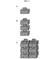
ここで使用されるバッテリーは複数の電気化学セルを備えることができる。図1を参照すると、電気化学セル(A)は、アノードとカソードとを備えるユニットである。セルは、電解質を備えてもよく、また、本明細書中に記載されるようなハウジング内にシールされてもよい。ある場合には、バッテリーを形成するために電気化学セルを積み重ねることができる(B)(すなわち、電気化学セルの編成)。セルは、並列に、直列に、あるいは、並列および直列の両方を成して配置され得る(C)。セルは、描かれるものと異なってもよい様々な形状および幾何学的形態に形成され得る。
Battery and Housing The battery used here can comprise a plurality of electrochemical cells. Referring to FIG. 1, the electrochemical cell (A) is a unit including an anode and a cathode. The cell may comprise an electrolyte and may be sealed within a housing as described herein. In some cases, electrochemical cells can be stacked to form a battery (B) (ie, the organization of electrochemical cells). Cells can be placed in parallel, in series, or both in parallel and in series (C). The cells may be formed in a variety of shapes and geometric forms that may differ from those depicted.
本開示の電気化学セルは、適切に多い量のエネルギーを蓄える(および/または取り入れる)ことができてもよい。ある場合には、セルは、約1Wh、約5Wh、約25Wh、約50Wh、約100Wh、約500Wh、約1kWh、約1.5kWh、約2kWh、約3kWh、または、約5kWhを蓄える(および/または取り入れる)ことができる。ある場合には、バッテリーは、少なくとも約1Wh、少なくとも約5Wh、少なくとも約25Wh、少なくとも約50Wh、少なくとも約100Wh、少なくとも約500Wh、少なくとも約1kWh、少なくとも約1.5kWh、少なくとも約2kWh、少なくとも約3kWh、または、少なくとも約5kWhを蓄える(および/または取り入れる)ことができる。電気化学セルおよび/またはバッテリーに蓄えられるエネルギーの量が(例えば、効率の悪さおよび損失に起因して)電気化学セルおよび/またはバッテリーに取り込まれるエネルギーの量より少ない場合があることが分かる。 The electrochemical cells of the present disclosure may be able to store (and / or incorporate) a suitably large amount of energy. In some cases, the cell stores about 1 Wh, about 5 Wh, about 25 Wh, about 50 Wh, about 100 Wh, about 500 Wh, about 1 kWh, about 1.5 kWh, about 2 kWh, about 3 kWh, or about 5 kWh (and / or Can be taken in). In some cases, the battery has at least about 1 Wh, at least about 5 Wh, at least about 25 Wh, at least about 50 Wh, at least about 100 Wh, at least about 500 Wh, at least about 1 kWh, at least about 1.5 kWh, at least about 2 kWh, at least about 3 kWh, Alternatively, at least about 5 kWh can be stored (and / or incorporated). It will be appreciated that the amount of energy stored in the electrochemical cell and / or battery may be less than the amount of energy taken into the electrochemical cell and / or battery (eg, due to inefficiency and loss).
セルの編成(すなわちバッテリー)は、少なくとも約2個、少なくとも約5個、少なくとも約10個、少なくとも約50個、少なくとも約100個、少なくとも約500個、少なくとも約1000個、少なくとも約5000個、少なくとも約10000個などの任意の適した数のセルを含むことができる。幾つかの例において、バッテリーは、1,2,3,4,5,6,7,8,9,10,15,20,30,40,50,60,70,80,90,100,200,300,400,500,600,700,800,900,1000,2000,5000,10,000,20,000,50,000,100,000,500,000、または、1,000,000個のセルを含む。 The cell organization (ie, battery) is at least about 2, at least about 5, at least about 10, at least about 50, at least about 100, at least about 500, at least about 1000, at least about 5000, at least Any suitable number of cells can be included, such as about 10,000. In some examples, the batteries are 1, 2, 3, 4, 5, 6, 7, 8, 9, 10, 15, 20, 30, 40, 50, 60, 70, 80, 90, 100, 200. 300,400,500,600,700,800,900,1000,2000,5000,10,000,20,000,50,000,100,000,500,000, or 1,000,000 Contains cells.
本開示のバッテリーは、電力網(すなわち、配電網スケールのバッテリー)または他の負荷または用途と共に用いるのに適した多量のエネルギーを蓄えることができてもよい。ある場合には、バッテリーは、約5kWh、約25kWh、約50kWh、約100kWh、約500kWh、約1MWh、約1.5MWh、約2MWh、約3MWh、または、約5MWhを蓄える(および/または取り入れる)ことができる。ある場合には、バッテリーは、少なくとも約5kWh、少なくとも約25kWh、少なくとも約50kWh、少なくとも約100kWh、少なくとも約500kWh、少なくとも約1MWh、少なくとも約1.5MWh、少なくとも約2MWh、少なくとも約3MWh、または、少なくとも約5MWhを蓄える(および/または取り入れる)ことができる。 The batteries of the present disclosure may be capable of storing large amounts of energy suitable for use with power grids (ie, grid-scale batteries) or other loads or applications. In some cases, the battery stores (and / or incorporates) about 5 kWh, about 25 kWh, about 50 kWh, about 100 kWh, about 500 kWh, about 1 MWh, about 1.5 MWh, about 2 MWh, about 3 MWh, or about 5 MWh. Can do. In some cases, the battery has at least about 5 kWh, at least about 25 kWh, at least about 50 kWh, at least about 100 kWh, at least about 500 kWh, at least about 1 MWh, at least about 1.5 MWh, at least about 2 MWh, at least about 3 MWh, or at least about 5 MWh can be stored (and / or incorporated).
ある場合には、セルおよびセルハウジングを積み重ねることができる。任意の適した数のセルを積み重ねることができる。セルは、並んで、互いの上に、または、これらの両方で積み重ねることができる。ある場合には、少なくとも約10,50,100、または、500個のセルを積み重ねることができる。ある場合には、100個のセルの積層体は、少なくとも50kWhのエネルギーを蓄えることができる。セル(例えば、10個のセル)の第1の積層体をセル(例えば、他の10個のセル)の第2の積層体に電気的に接続して、電気的に通じるセルの数(例えば、この場合には20個)を増やすことができる。ある場合には、エネルギー蓄積デバイスは、1〜10個、11〜50個、51〜100個またはそれ以上の電気化学セルの積層体を備える。 In some cases, cells and cell housings can be stacked. Any suitable number of cells can be stacked. The cells can be stacked side by side, on top of each other, or both. In some cases, at least about 10, 50, 100, or 500 cells can be stacked. In some cases, a stack of 100 cells can store at least 50 kWh of energy. Electrically connecting a first stack of cells (e.g., 10 cells) to a second stack of cells (e.g., the other 10 cells) and the number of electrically communicating cells (e.g., In this case, 20) can be increased. In some cases, the energy storage device comprises a stack of 1-10, 11-50, 51-100 or more electrochemical cells.
セル蓋アセンブリ
電気化学セルは、容器蓋を含むことができる容器内に収容され得る。ある場合には、容器が電気化学セルの電極である。容器蓋は、例えば、バッテリー容器を容器蓋から電気的に絶縁するためにシールまたはガスケット(例えば、環状誘電体ガスケット)を利用してもよい。そのようなガスケットは、例えばガラス、シリコン酸化物、酸化アルミニウム、窒化ホウ素、窒化アルミニウム、または、酸化リチウム、酸化カルシウム、酸化バリウム、酸化イットリウム、酸化ケイ素を含む他の酸化物、窒化リチウム、あるいは、他のセラミックなどの比較的硬い電気絶縁材料から構成されてもよい。ガスケットは、電気的絶縁に加えてシールを行なうために、容器蓋とバッテリー容器との間で比較的高い圧縮力(例えば、10,000psiよりも大きい)に晒されてもよい。誘電体ガスケットをそのような高い圧縮力に晒すために、複数の締結具が、比較的大きな直径を有してもよく、互いに接近して離間されてもよい。そのような大径締結具は、高価な場合があり、したがって、比較的大径のバッテリー容器を形成するためのコストをかなり増大させる場合がある。また、大径バッテリー容器に対応するために誘電体ガスケットの直径が増大されるため、ガスケットがますます脆弱となって、ガスケットの取り扱いが難しくなり得る。
Cell Lid Assembly The electrochemical cell can be contained in a container that can include a container lid. In some cases, the container is an electrode of an electrochemical cell. The container lid may utilize, for example, a seal or gasket (eg, an annular dielectric gasket) to electrically insulate the battery container from the container lid. Such gaskets are, for example, glass, silicon oxide, aluminum oxide, boron nitride, aluminum nitride, or other oxides including lithium oxide, calcium oxide, barium oxide, yttrium oxide, silicon oxide, lithium nitride, or It may be composed of a relatively hard electrically insulating material such as other ceramics. The gasket may be exposed to a relatively high compressive force (eg, greater than 10,000 psi) between the container lid and the battery container to provide a seal in addition to electrical insulation. In order to expose the dielectric gasket to such high compressive forces, the plurality of fasteners may have a relatively large diameter and may be spaced close together. Such large diameter fasteners can be expensive and therefore can significantly increase the cost of forming a relatively large diameter battery container. Also, because the diameter of the dielectric gasket is increased to accommodate large battery containers, the gasket becomes increasingly brittle and the handling of the gasket can be difficult.
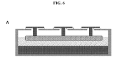
図2を参照すると、バッテリーは、導電ハウジング201と、電流コレクタ203と電気的に通じる導体202とを備える。導体は、ハウジングから電気的に絶縁されてもよく、また、第1および第2のセルが積み重ねられるときに第1のセルの導体が第2のセルのハウジングと接触するようにハウジングの開口を通じてハウジングから突出してもよい。
Referring to FIG. 2, the battery includes a
一態様において、セルハウジングは、導電容器と、電流コレクタと電気的に通じる導体とを備える。導体は、容器の開口を通じてハウジングから突出してもよく、また、容器から電気的に絶縁される。第1のハウジングの導体は、第1および第2のハウジングが積み重ねられるときに第2のハウジングの容器と接触してもよい。 In one aspect, the cell housing comprises a conductive container and a conductor in electrical communication with the current collector. The conductor may protrude from the housing through the opening of the container and is electrically isolated from the container. The conductor of the first housing may contact the container of the second housing when the first and second housings are stacked.
ある場合には、導体がハウジングおよび/または容器から突出する開口の面積は、ハウジングおよび/または容器の面積に対して小さい。ある場合には、ハウジングの面積に対する開口の面積の比率は、約0.001、約0.005、約0.01、約0.05、約0.1、約0.15、約0.2、約0.3、約0.4、または、約0.5である。ある場合には、ハウジングの面積に対する開口の面積の比率は、0.001未満、0.005未満、0.01未満、0.05未満、0.1未満、0.15未満、0.2未満、0.3未満、0.4未満、または、0.5未満である。 In some cases, the area of the opening through which the conductor projects from the housing and / or container is small relative to the area of the housing and / or container. In some cases, the ratio of the area of the opening to the area of the housing is about 0.001, about 0.005, about 0.01, about 0.05, about 0.1, about 0.15, about 0.2. , About 0.3, about 0.4, or about 0.5. In some cases, the ratio of the area of the opening to the area of the housing is less than 0.001, less than 0.005, less than 0.01, less than 0.05, less than 0.1, less than 0.15, less than 0.2. , Less than 0.3, less than 0.4, or less than 0.5.
一態様において、セルは、導電ハウジングと、電流コレクタと電気的に通じる導体とを備える。導体は、ハウジングの開口を通じてハウジングから突出し、また、ハウジングから電気的に絶縁されてもよい。ハウジングの面積に対する開口の面積の比率は約0.1未満であってもよい。 In one aspect, the cell includes a conductive housing and a conductor in electrical communication with the current collector. The conductor protrudes from the housing through the opening in the housing and may be electrically isolated from the housing. The ratio of the area of the opening to the area of the housing may be less than about 0.1.
一態様において、セルハウジングは、導電容器と、電流コレクタと電気的に通じる導体とを備える。導体は、容器の開口を通じて容器から突出し、また、容器から電気的に絶縁される。容器の面積に対する開口の面積の比率は約0.1未満であってもよい。ハウジングは、少なくとも25Whのエネルギーを蓄えるおよび/または取り入れることができるセルを収容することができる。 In one aspect, the cell housing comprises a conductive container and a conductor in electrical communication with the current collector. The conductor protrudes from the container through the opening of the container and is electrically insulated from the container. The ratio of the area of the opening to the area of the container may be less than about 0.1. The housing can contain a cell capable of storing and / or taking in at least 25 Wh of energy.
ある場合には、導体は、ガスケットまたはシールを用いてハウジングから電気的に絶縁される。図3は、容器305に溶接され得るセル蓋アセンブリ301を示す。少なくとも1つの導電フィードスルー(すなわち導体)が蓋アセンブリを貫通して液体アノード302と電気的に通じる。幾つかの実施形態では、電流コレクタが導電発泡体であり、その場合、アノードが液体金属(例えば、リチウム、マグネシウム、ナトリウム)を備える。アノードが溶融塩電解質304と接触し、溶融塩電解質304が液体金属カソード303と接触する。幾つかの実施形態では、液体金属カソードが鉛およびアンチモンを備える。
In some cases, the conductor is electrically isolated from the housing using a gasket or seal. FIG. 3 shows a
図4は、導体401、ハウジング開口、および、導体をハウジング402から電気的に絶縁するとともに電気化学セルをシールするための関連する構造体を示す。幾つかの実施形態では、少なくとも1つのボルト403がアセンブリを所定位置に保持する。ボルトは、ハウジングと電気的に通じることができるとともに、導電フィードスルーから電気的に絶縁される。幾つかの実施形態では、ボルトが上側フランジ404を下側フランジ405と押し付ける。ある場合には、下側フランジがセル蓋に溶接される。電気絶縁ワッシャまたはワッシャアセンブリ406がボルトを上側フランジから絶縁できる。ある場合には、誘電体ガスケット407が上側フランジを下側フランジから絶縁する。ある場合には、ボルトが上側フランジと接触しないように誘電体シース(図示せず)を使用することができる。ある場合には、フィードスルー導体がマイナス極性を有し(例えば、アノードと電気的に通じ)、また、ボルトおよびハウジングがプラス極性を有する(例えば、カソードと電気的に通じる)。
FIG. 4 shows the
シールされると、ガスケットに印加される力は、約1,000psi、約2,000psi、約5,000psi、約10,000psi、約15,000psi、または、約30,000psiとなり得る。ある場合には、ガスケットに印加される力は、少なくとも1,000psi、少なくとも2,000psi、少なくとも5,000psi、少なくとも10,000psi、少なくとも15,000psi、または、少なくとも30,000psiとなり得る。 Once sealed, the force applied to the gasket can be about 1,000 psi, about 2,000 psi, about 5,000 psi, about 10,000 psi, about 15,000 psi, or about 30,000 psi. In some cases, the force applied to the gasket can be at least 1,000 psi, at least 2,000 psi, at least 5,000 psi, at least 10,000 psi, at least 15,000 psi, or at least 30,000 psi.
ある場合には、セルは、導電ハウジングと、電流コレクタと電気的に通じる導体とを備える。導体は、ハウジングの開口を通じてハウジングから突出することができるとともに、ガスケットを用いてハウジングから絶縁される。ガスケットに作用する力は、少なくとも1,000psi、少なくとも5.000psi、少なくとも10,000psi等であってもよい。 In some cases, the cell includes a conductive housing and a conductor in electrical communication with the current collector. The conductor can protrude from the housing through the opening in the housing and is insulated from the housing using a gasket. The force acting on the gasket may be at least 1,000 psi, at least 5.000 psi, at least 10,000 psi, and the like.
セルハウジングは、導電容器と、電流コレクタと電気的に通じる導体とを備えることができる。導体は、容器の開口を通じて容器から突出してもよく、また、ガスケットを用いて容器から絶縁されてもよい。ガスケットに作用する力は、少なくとも1,000psi、少なくとも5,000psi、少なくとも10,000psi等であってもよい。 The cell housing can comprise a conductive container and a conductor in electrical communication with the current collector. The conductor may protrude from the container through the opening of the container and may be insulated from the container using a gasket. The force acting on the gasket may be at least 1,000 psi, at least 5,000 psi, at least 10,000 psi, and the like.
少ないボルトおよび締結具
ボルトおよび締結具は、バッテリーおよびハウジングのコストを大幅に増大させ得る。ある場合には、バッテリーまたはバッテリーハウジングが数少ないボルトまたは締結具を備える。幾つかの実施形態において、バッテリーまたはバッテリーハウジングは、約50個、約40個、約30個、約20個、約10個、約5個、または、約2個のボルトまたは締結具を備える。バッテリーまたはバッテリーハウジングがボルトまたは締結具を備えなくてもよい。幾つかの実施形態において、バッテリーまたはバッテリーハウジングは、50個未満、40個未満、30個未満、20個未満、10個未満、5個未満、または、2個未満のボルトまたは締結具を備える。他の実施形態では、誘電体シール材料がセル蓋およびフィードスルーリードの表面に機械的および/または化学的に付着され、それにより、ボルトまたは締結具をセルに必要とすることなくシステムが密閉気密シールを得ることができるようにしてもよい。例えばセルの積み重ねによってあるいはセルの上端に錘を加えることによって、圧力がフィードスルーの上端に印加され、それにより、シールの性能および耐久性が向上されてもよい。
Fewer bolts and fasteners Bolts and fasteners can significantly increase battery and housing costs. In some cases, the battery or battery housing includes a few bolts or fasteners. In some embodiments, the battery or battery housing comprises about 50, about 40, about 30, about 20, about 10, about 5, or about 2 bolts or fasteners. The battery or battery housing may not include bolts or fasteners. In some embodiments, the battery or battery housing comprises less than 50, less than 40, less than 30, less than 20, less than 10, less than 5, or less than 2 bolts or fasteners. In other embodiments, a dielectric seal material is mechanically and / or chemically attached to the surface of the cell lid and feedthrough leads so that the system is hermetically sealed without the need for bolts or fasteners to the cell. A seal may be obtained. Pressure may be applied to the top of the feedthrough, for example by stacking cells or by applying a weight to the top of the cell, thereby improving the performance and durability of the seal.
バッテリーは、アノード、カソード、電解質、プラス電流コレクタ、および、マイナス電流コレクタを備えることができる。マイナス電流コレクタがアノードと接触することができ、また、プラス電流コレクタがカソードと接触する。バッテリーは、少なくとも25Whのエネルギーを蓄えるおよび/または取り入れることができるとともに、10個未満のボルトまたは締結具を備える。 The battery can include an anode, a cathode, an electrolyte, a positive current collector, and a negative current collector. A negative current collector can be in contact with the anode, and a positive current collector is in contact with the cathode. The battery can store and / or capture at least 25 Wh of energy and includes less than 10 bolts or fasteners.
ある場合には、セルの編成は、少なくとも25Wh、200Wh、300Wh、400Wh、500Wh、600Wh、700Wh、800Wh、900Wh、1,000Wh、2,000Wh、3,000Wh、4,000Wh、5,000Wh、6,000Wh、7,000Wh、8,000Wh、9,000Wh、10,000Wh、20,000Wh、30,000Wh、40,000Wh、または、50,000Whのエネルギーを蓄えることができ、また、それぞれのセルは、20,15,14,13,12,11,10,9,8,7,6,5,4,3,2または1個未満のボルトまたは締結具を備える。幾つかの例では、セル構成要素を互いに溶接することができる。
In some cases, the cell organization is at least 25 Wh, 200 Wh, 300 Wh, 400 Wh, 500 Wh, 600 Wh, 700 Wh, 800 Wh, 900 Wh, 1,000 Wh, 2,000 Wh, 3,000 Wh, 4,000 Wh, 5,000 Wh, 6 , 000 Wh, 7,000 Wh, 8,000 Wh, 9,000 Wh, 10,000 Wh, 20,000 Wh, 30,000 Wh, 40,000 Wh, or 50,000 Wh, and each cell can store
セルハウジングは、少なくとも25Whのエネルギーを蓄えるおよび/または取り入れることができるセルを密閉シールすることができる。ハウジングは、20,15,14,13,12,11,10,9,8,7,6,5,4,3,2または1個未満のボルトまたは締結具を備える。 The cell housing can hermetically seal cells that can store and / or incorporate at least 25 Wh of energy. The housing comprises 20, 15, 14, 13, 12, 11, 10, 9, 8, 7, 6, 5, 4, 3, 2 or less than one bolt or fastener.
セル蓋アセンブリは、フランジおよびガスケットの代わりに接着シールを使用できる。ある場合には、接着シールが電気化学セルハウジングからボルトを排除する。図5に見られるように、導電フィードスルー501がハウジングから電気的に絶縁され、また、ハウジングは、フィードスルーとハウジングとの間に配置される接着シール材料502によってシールされる。
The cell lid assembly can use an adhesive seal in place of the flange and gasket. In some cases, the adhesive seal eliminates the bolt from the electrochemical cell housing. As seen in FIG. 5, the
ある場合には、ボルトを使用しない接着誘電体シールを用いてシールされるセルにおいて、気密シールを維持するために必要とされる圧力は1psi未満で足り得る。ある場合には、バッテリー内で互いに積み重ねられる1つ以上の電気化学セルの重量によって圧力の少なくとも一部を与えることができる。接着シール材料は、ガラスシールまたは蝋付けされたセラミック、例えばCu−Ag蝋付け合金を伴うアルミナ、あるいは、他のセラミック−蝋付け組み合わせを備えることができる。 In some cases, in cells sealed with an adhesive dielectric seal that does not use bolts, the pressure required to maintain a hermetic seal may be less than 1 psi. In some cases, at least a portion of the pressure can be provided by the weight of one or more electrochemical cells stacked together in the battery. The adhesive seal material may comprise a glass seal or brazed ceramic, such as alumina with a Cu-Ag brazing alloy, or other ceramic-brazing combinations.
ボルトおよびフランジではなく接着材料を用いて電気化学セルをシールすると、蓋アセンブリがハウジングよりも上側に延びることができる高さ(「ヘッドスペース」)を減らすことができる。積層バッテリー形態では、バッテリーの比較的大きな容積がアノード材料およびカソード材料を構成できる(すなわち、より高いエネルギー蓄積能力)ようにヘッドスペースを減らすことが望ましい場合がある。ある場合には、ヘッドスペースの幅(フィードスルーの上端からアノードの上端面まで測定される)は、バッテリーの幅(フィードスルーの上端からハウジングの下端面まで測定される)のごく一部である。幾つかの実施形態において、ヘッドスペースは、バッテリーの高さの約5%、約10%、約15%、約20%、または、約25%である。幾つかの実施形態において、ヘッドスペースは、バッテリーの高さの最大で約5%、最大で約10%、最大で約15%、最大で約20%、または、最大で約25%である。 Sealing the electrochemical cell with adhesive material rather than bolts and flanges can reduce the height (“head space”) that the lid assembly can extend above the housing. In stacked battery configurations, it may be desirable to reduce headspace so that a relatively large volume of the battery can constitute the anode and cathode materials (ie, higher energy storage capacity). In some cases, the width of the headspace (measured from the top of the feedthrough to the top of the anode) is a fraction of the width of the battery (measured from the top of the feedthrough to the bottom of the housing). . In some embodiments, the headspace is about 5%, about 10%, about 15%, about 20%, or about 25% of the battery height. In some embodiments, the headspace is up to about 5% of battery height, up to about 10%, up to about 15%, up to about 20%, or up to about 25%.
幾つかの実施形態において、アノードとカソードとの組み合わせ容積は、バッテリーの容積(例えば、運送用コンテナなどのバッテリーの最も外側のハウジングによって規定される)の約50%、約60%、約70%、約80%、約90%、または、約95%である。幾つかの実施形態において、アノードとカソードとの組み合わせ容積は、バッテリーの容積の少なくとも約50%、少なくとも約60%、少なくとも約70%、少なくとも約80%、少なくとも約90%、または、少なくとも約95%である。 In some embodiments, the combined volume of anode and cathode is about 50%, about 60%, about 70% of the volume of the battery (eg, defined by the outermost housing of the battery, such as a shipping container). , About 80%, about 90%, or about 95%. In some embodiments, the combined volume of anode and cathode is at least about 50%, at least about 60%, at least about 70%, at least about 80%, at least about 90%, or at least about 95% of the volume of the battery. %.
ある状況では、少ない数のあるいはたった1つの導電フィードスルーの使用が不均一な電流分布を電極にもたらす可能性がある。本明細書中に記載されるように、複数の導電フィードスルーが電極で電流をより均一に分布させることができる。 In certain situations, the use of a small number or only one conductive feedthrough can result in a non-uniform current distribution in the electrode. As described herein, multiple conductive feedthroughs can more uniformly distribute the current at the electrodes.
一態様において、電気化学エネルギー蓄積デバイスは、ハウジングと、液体金属電極と、液体金属電極と接触する電流コレクタと、電流コレクタと電気的に通じるとともにハウジングの開口を通じてハウジングから突出する複数の導体とを備える。幾つかの実施形態では、電流が液体金属電極にわたって略均一に分布される。 In one aspect, an electrochemical energy storage device includes a housing, a liquid metal electrode, a current collector in contact with the liquid metal electrode, and a plurality of conductors in electrical communication with the current collector and projecting from the housing through the opening in the housing. Prepare. In some embodiments, the current is distributed substantially uniformly across the liquid metal electrode.
幾つかの実施形態では、液体金属電極が表面(および/または界面)に沿って電解質と接触し、また、表面(および/または界面)にわたって流れる電流が均一である。表面(および/または界面)の任意の部分を通じて流れる電流は、平均電流から大きく逸脱しない。幾つかの実施形態において、表面(および/または界面)の領域にわたって流れる電流の最大密度は、表面(および/または界面)にわたって流れる電流の平均密度の約105%未満、約115%未満、約125%未満、約150%未満、約175%未満、約200%未満、約250%未満、または、約300%未満である。幾つかの実施形態において、表面(および/または界面)の領域にわたって流れる電流の最小密度は、表面(および/または界面)にわたって流れる電流の平均密度の約50%を超える、約60%を超える、約70%を超える、約80%を超える、約90%を超える、または、約95%を超える。 In some embodiments, the liquid metal electrode contacts the electrolyte along the surface (and / or interface) and the current flowing across the surface (and / or interface) is uniform. The current flowing through any part of the surface (and / or interface) does not deviate significantly from the average current. In some embodiments, the maximum density of current flowing over the surface (and / or interface) region is less than about 105%, less than about 115%, about 125% of the average density of current flowing over the surface (and / or interface). %, Less than about 150%, less than about 175%, less than about 200%, less than about 250%, or less than about 300%. In some embodiments, the minimum density of current flowing across the surface (and / or interface) region is greater than about 50%, greater than about 60% of the average density of current flowing across the surface (and / or interface); Greater than about 70%, greater than about 80%, greater than about 90%, or greater than about 95%.
図6は複数の導電フィードスルーを示す。電気化学蓄電デバイスおよび/またはハウジングは、任意の数(例えば、2,3,4,5,6,7,8,9,10,11,12,13,14,15,16,17,18,19,20またはそれ以上)の導電フィードスルーを備えることができる。ある場合には、導電フィードスルーが別個のものである(パネルA)。ある場合には、導電フィードスルーが共通の上部を共有する(パネルB)。 FIG. 6 shows a plurality of conductive feedthroughs. Any number of electrochemical storage devices and / or housings (eg, 2, 3, 4, 5, 6, 7, 8, 9, 10, 11, 12, 13, 14, 15, 16, 17, 18, 19, 20 or more) can be provided. In some cases, the conductive feedthrough is separate (panel A). In some cases, conductive feedthroughs share a common top (panel B).
セルの密閉シール
密閉シールされたバッテリーまたはバッテリーハウジングは、不適切な量の空気、酸素、および/または、水がバッテリー内へ入ることを防止してもよい(例えば、バッテリーが少なくとも1年、少なくとも2年、少なくとも5年、少なくとも10年、または、少なくとも20年にわたってそのエネルギー蓄積能力の少なくとも80%を維持するような量)。
Cell hermetic seal A hermetically sealed battery or battery housing may prevent inappropriate amounts of air, oxygen, and / or water from entering the battery (eg, the battery is at least one year, at least Amount that maintains at least 80% of its energy storage capacity for 2 years, at least 5 years, at least 10 years, or at least 20 years).
ある場合には、バッテリー内への酸素、窒素、および、水蒸気の移動の割合は、バッテリーが1バールの圧力および400〜700℃の温度で空気と接触されるときに、約0.25mL/時未満である。幾つかの実施形態において、10年の期間にわたってセル内へ漏れる酸素、窒素、または、水蒸気のモル数は、セル内の活性金属材料のモル数の10%未満である。 In some cases, the rate of oxygen, nitrogen, and water vapor transfer into the battery is about 0.25 mL / hour when the battery is contacted with air at a pressure of 1 bar and a temperature of 400-700 ° C. Is less than. In some embodiments, the number of moles of oxygen, nitrogen, or water vapor that leak into the cell over a period of 10 years is less than 10% of the number of moles of active metal material in the cell.
一態様では、バッテリーがアノードとカソードとを備える。バッテリーは、少なくとも10whのエネルギーを蓄えることができるとともに、密閉シールまたは非密閉シールされる。アノードおよびカソードの少なくとも一方が液体金属であってもよい。ある場合には、アノードが液体金属(例えば、リチウム、マグネシウム、ナトリウム)である。 In one aspect, the battery comprises an anode and a cathode. The battery can store at least 10 wh of energy and is hermetically sealed or non-hermetically sealed. At least one of the anode and the cathode may be a liquid metal. In some cases, the anode is a liquid metal (eg, lithium, magnesium, sodium).
一態様では、一群のバッテリーが少なくとも10Whのエネルギーを蓄えることができ、また、各バッテリーが密閉シールまたは非密閉シールされる。 In one aspect, a group of batteries can store at least 10 Wh of energy and each battery is hermetically sealed or non-hermetically sealed.
一態様において、バッテリーハウジングは、導電容器、容器開口、および、電流コレクタと電気的に通じる導体を備える。導体は、容器開口を貫通してもよく、また、導電容器から電気的に絶縁される。ハウジングは、少なくとも100kWhのエネルギーを蓄えることができるバッテリーを密閉シールできてもよい。 In one aspect, the battery housing comprises a conductive container, a container opening, and a conductor in electrical communication with the current collector. The conductor may penetrate the container opening and is electrically insulated from the conductive container. The housing may be capable of hermetically sealing a battery capable of storing at least 100 kWh of energy.
電気化学セル、バッテリー、および、バッテリーハウジングの実施形態
図7は、本発明の一実施形態に係る電気化学セル20を示す。セル20は、電気化学セルハウジング24内にシールされる(例えば、密閉シールされる)少なくとも1つの電気化学セル22を含む。セルハウジング24は、セル容器26、容器蓋アセンブリ28、および、1つ以上の導体30(例えば、導体ロッド)を含む。セルハウジング24は、熱的および/または電気的絶縁シース32、第1の(例えば、マイナス)電流コレクタ34、および、第2の(例えば、プラス)電流コレクタ36も含むことができる。
Electrochemical Cell, Battery, and Battery Housing Embodiment FIG. 7 shows an
バッテリーセル22は液体金属バッテリーセルとして構成されてもよい。バッテリーセル22は、例えば、液体の第1の(例えば、マイナス)電極40と液体の第2の(例えば、プラス)電極42との間に軸方向に配置される液体セパレータ38を含んでもよい。
The
ある場合には、電気化学バッテリーが図7におけるそれから逸脱する。例えば、上側電極40が上側電流コレクタ(例えば、発泡体)34内に収容され得る。この実施形態では、塩層が発泡体34の底面および側面と接触し、また、発泡体中の上端金属が側壁32または26から離れるように保持され、それにより、セルが絶縁シース32なしで延びることができる。ある場合には、側壁の上方へのカソードの「クリープ」を防止するためにグラファイトシースが使用され、それにより、セルの短絡を防止できる。
In some cases, the electrochemical battery deviates from that in FIG. For example, the
セパレータ38はイオン伝導性液体電解質であってもよい。液体電解質の一例は、例えば、フッ化塩、塩化物塩、臭化物塩、ヨウ化物塩、または、これらの組み合わせなどの1つ以上のイオン伝導性溶融塩の溶液である。第1の電極40が液体(例えば、溶融)金属であってもよい。第1の電極40として使用されてもよい材料の例としては、制限なく、ナトリウム(Na)、カリウム(K)、リチウム(Li)、カルシウム(Ca)、バリウム(Ba)、マグネシウム(Mg)、または、これらの組み合わせが挙げられる。第1の電極40の液体金属は、リストに挙げられた例のうちの1つ以上を含んでもよい。第2の電極42は液体金属または半金属であってもよい。第2の電極42として使用されてもよい材料の例としては、制限なく、アンチモン(Sb)、鉛(Pb)、スズ(Sn)、ビスマス(Bi)、テルル(Te)、セレン(Se)、または、これらの組み合わせが挙げられる。第2の電極42は、先に挙げられた金属または半金属のうちの1つ以上を含んでもよい。セパレータ、第1の電極、および、第2の電極の材料および/または形態の他の例は、米国特許出願公開第2008/0044725号、第2011/0014503号、第2011/0014505号、および、第2012/0104990号に開示されており、これらの出願のそれぞれは、参照することにより全体が本願に組み入れられる。しかしながら、本発明は、任意の特定のバッテリーセル形態および/または材料に限定されない。
The
バッテリー容器26は、例えば、鋼、鉄、ステンレス鋼、グラファイト、ニッケル、ニッケル系合金、チタン、アルミニウム、モリブデン、タングステン、または、導電ガラスなどの導電材料から構成され得る。セル容器は、例えばグラファイトライニングを伴うスチール容器または窒化ホウ素コーティングを伴うスチール容器など、構造体構成要素と、別個の金属コーティングまたは電気絶縁コーティングの更に薄いライニング構成要素とを備えてもよい。バッテリー容器26は、第1の容器端部(例えば、縁)44と第2の容器端部(例えば、縁)46との間で軸方向に延びることができる断面形状を有することができる。断面形状は、例えば、図13に示されるような円形、図16に示されるような矩形(例えば、正方形)、または、バッテリー20のための設計要件に基づいて選択されてもよい任意の他の形状であってもよい。バッテリー容器26は、容器(下)端壁50と容器側壁52とによって画定されるセルキャビティ48を含む。キャビティ48は、第1の容器端部44に位置されるキャビティ開口54から第2の容器端部46に位置される容器端壁50までバッテリー容器26内へと軸方向に延びることができる。また、キャビティ48は、容器側壁52の対向する側面間で横方向にも延びることができる。
The
容器蓋アセンブリ28は、導電容器蓋56、1つ以上の導電フランジ58、および、1つ以上の電気絶縁ガスケット60(例えば、環状誘電体ガスケット)を含むことができる。
The
図8および図9を参照すると、容器蓋56は、例えば、鋼、鉄、銅、ステンレス鋼、グラファイト、ニッケル、ニッケル系合金、チタン、アルミニウム、モリブデン、タングステン、または、導電ガラスなどの導電材料から構成され得る。容器蓋56は、第1の蓋端部62と第2の蓋端部64との間で軸方向に延びることができる。容器蓋56は、導電ベース66と、1つ以上の導電装着リング68(「フィードスルーフランジ」とも称される)とを含むことができる。ベースは、第1の蓋端部62とベース端部70との間で軸方向に延びることができ、ベース端部70は、軸方向で第1の蓋端部62と第2の蓋端部64との間に位置される。ベース66は、第1の蓋端部62とベース端部70との間でベース66を軸方向に貫通して延びることができる1つ以上の装着リング開口72を含むことができる。装着リング68はそれぞれ装着リング開口72と嵌合されてベース66に接続される(例えば、溶接される、接着される、あるいはさもなければ、締結される)。装着リング68は、第1の蓋端部62と第2の蓋端部64との間で軸方向に延びることができる。装着リング68のそれぞれは、第1の蓋端部62と第2の蓋端部64との間で装着リングを軸方向で貫通して延びることができる第1の導体開口74を含む。第1の導体開口74は、キャビティ開口54(図7参照)の直径よりも例えば少なくとも2(例えば、約2〜6)倍小さい直径を有する。各装着リング68は、それぞれの第1の導体開口74の周囲にわたって配置される1つ以上のネジ付き締結具開口76を含んでもよい。締結具開口76は、第1の蓋端部62からそれぞれの装着リング68内へと軸方向に延びる。
Referring to FIGS. 8 and 9, the
図10および図11を参照すると、フランジ58のそれぞれは、例えば、鋼、鉄、ステンレス鋼、グラファイト、ニッケル、ニッケル系合金、チタン、アルミニウム、モリブデン、タングステン、または、導電ガラスなどの導電材料から構成される。各フランジ58は、第1のフランジ端部78と第2のフランジ端部80との間で軸方向に延びることができる。各フランジ58は導電ベース82と導電フランジリング84とを含んでもよい。ベース82は、第1のフランジ端部78と第2のフランジ端部80との間で軸方向に延びることができる。ベース82は、第2のフランジ端部80からベース端壁88まで軸方向でベース82内へと延びることができるネジ付き導体開口86を含む。フランジリング84はベース82の周囲にわたって延びることができる。また、フランジリング84は、第1のフランジリング端部90と第2のフランジリング端部92との間で軸方向に延びることができる。第1のフランジリング端部90は、第1のフランジ端部78から第1の軸方向距離だけオフセットされてもよく、および/または、第2のフランジリング端部92は、第2のフランジ端部80から第2の軸方向距離だけオフセットされてもよい。フランジリング84は、ベース82の周囲にわたって配置される複数の締結具開口94を含んでもよい。締結具開口94は、第1のフランジリング端部90と第2のフランジリング端部92との間でフランジリング84を軸方向で貫通して延びる。
Referring to FIGS. 10 and 11, each of the
図7および図12を参照すると、ガスケット60は、例えば、ガラス、蝋付けセラミック、サーミキュライト、窒化アルミニウム、マイカ、および/または、バーミキュライトなどの誘電体材料から構成される。各ガスケット60は、第1のガスケット端部98と第2のガスケット端部100との間でガスケットを貫通して軸方向に延びることができる第2の導体開口96を含む。第2の導体開口96は、第1の導体開口74のそれぞれの開口の直径にほぼ等しいあるいは該直径よりも小さい直径を有する。
Referring to FIGS. 7 and 12, the
図7を参照すると、導体30は、例えば、鋼、鉄、ステンレス鋼、グラファイト、ニッケル、ニッケル系合金、チタン、アルミニウム、モリブデン、または、タングステンなどの導電材料から構成され得る。導体30は、第1の導体端部102と第2の導体端部104との間で軸方向に延びる。各導体30は、第1の導体端部102付近にネジ付き端部領域106を含んでもよい。
Referring to FIG. 7, the
図7を参照すると、シース32は、例えば、アルミナ、チタニア、シリカ、マグネシア、窒化ホウ素、または、カルシウム酸化物、アルミニウム酸化物、シリコン酸化物、リチウム酸化物、マグネシウム酸化物等を含む混合酸化物などの断熱および/または電気絶縁材料から構成され得る。シース32は、第1のシース端部(上端)108と第2のシース端部(下端)110との間で軸方向に延びることができる環状の断面形状を有する。
Referring to FIG. 7, the
代案として、シースは、容器の腐食を防止するおよび/または側壁の上方へのカソード材料の湿潤を防止するために使用できるとともに、鋼、ステンレス鋼、タングステン、モリブデン、ニッケル、ニッケル系合金、グラファイト、または、チタンなどの電子伝導性材料から構成されてもよい。シースは、非常に薄くてもよく、また、コーティングであってもよい。コーティングは、壁の内側だけを覆うことができ、および/または、容器の内側の下端を覆うこともできる。 As an alternative, the sheath can be used to prevent corrosion of the vessel and / or wetting of the cathode material above the sidewalls, as well as steel, stainless steel, tungsten, molybdenum, nickel, nickel-based alloys, graphite, Alternatively, it may be made of an electron conductive material such as titanium. The sheath may be very thin and may be a coating. The coating may cover only the inside of the wall and / or may cover the bottom end inside the container.
図7および図12を参照すると、第1の電流コレクタ34は、例えば、ニッケル−鉄(Ni−Fe)発泡体、有孔スチールディスク、波形スチールのシート、エキスパンデッドメタルメッシュのシート等の導電材料から構成される。第1の電流コレクタ34は、第1のコレクタ端部112と第2のコレクタ端部114との間で軸方向に延びることができるプレートとして構成されてもよい。第1の電流コレクタ34は、キャビティ開口54の直径よりも小さく且つ第1の導体開口74の直径よりも大きいコレクタ直径を有する。他の電流コレクタ形態の例は、米国特許公開第2011/0014503号、第2011/0014505号、および、第2012/0104990号に開示されており、これらの特許は、参照することにより全体が本願に組み入れられる。本発明は任意の特定の第1の電流コレクタ形態に限定されない。
Referring to FIGS. 7 and 12, the first
第2の電流コレクタ36はセル容器26の一部として構成されてもよい。図7に示される実施形態では、例えば、容器端壁50が第2の電流コレクタ36として構成される。代案として、電流コレクタは、バッテリー容器とは別個であってもよく、また、例えば、バッテリー容器に電気的に接続される。そのような電流コレクタ配置の例は、前述した米国特許公開第2011/0014503号、第2011/0014505号、および、第2012/0104990号に開示されており、これらの特許は、参照することにより全体が本願に組み入れられる。本発明は任意の特定の第2の電流コレクタ形態に限定されない。
The second
図13および図14は、別の実施形態の電気化学バッテリーハウジング120を示す。そのようなケースのシースは、ある場合に、排除できる。図7および図12のバッテリーハウジング24とは異なり、バッテリーハウジング120の各フランジ58は、導体30のうちのそれぞれの1つに直接に接続される(例えば、溶接される、接着される、融着される、付着される、および/または、さもなければ締結される)フランジリング122を含む。バッテリーハウジング120の各ガスケット60は、締結具116を受ける複数の締結具開口124を更に含んでもよい。締結具116のそれぞれは、電気絶縁スリーブ126と電気絶縁ワッシャ128とによってフランジリング122から電気的に絶縁されてもよい。スリーブ126およびワッシャ128はそれぞれ、例えばマイカまたはバーミキュライトなどの誘電体から構成される。また、バッテリーハウジング120は、流体(例えば、不活性ガス)をシールされたキャビティ48内へ及び/またはキャビティ48から方向付ける1つ以上の流体ポート130(例えば、急速接続ガス器具)を含んでもよい。
FIGS. 13 and 14 show another embodiment of an
図15および図16は、他の別の実施形態の電気化学バッテリーハウジング132を示す。図7および図12のバッテリーハウジング24とは異なり、バッテリーハウジング132の各フランジ58は、第1のフランジリング端部90と第2のフランジ端部80との間で軸方向に延びることができるベース134を含む。各フランジ58は突出部136(例えば、ボス)を含むこともでき、突出部136は、ベース134および/またはフランジリング84に接続されるとともに、第1のフランジ端部78へと軸方向に延びることができる。そのような突出部136は、図15に示されるように、複数のバッテリーハウジング132を垂直に積み重ねるおよび/または電気的に相互接続するために利用されてもよい。
15 and 16 show another alternative embodiment
図17は、本明細書中に記載される電気化学セルおよび/またはバッテリーの部品数を減らす(例えば、単一の予め組み付けられた部品を使用して複数の電気化学セルの組み立てを可能にする)実施形態を示す。ある場合には、第1の電気化学セル1701の導体は、第2の電気化学セル1702のハウジング(例えば、プラス電流コレクタ)に接続され、および/または、第2の電気化学セル1702のハウジングと同じ金属部品から形成される。ある場合には、第1の電気化学セルの上端は、第1の電気化学セルの上方に位置される第2の電気化学セルの下端に直接に接続され(例えば、溶接されあるいはボルト締結され)、または、第2の電気化学セルの下端と同じ金属部品から形成される。セルは、図17中のパネルAに示されるように組み付けられ得る。ここに見られるように、ハウジング部分と容器蓋アセンブリ部分1704とを備える複数の部品1703は、複数の電気化学セルを形成するために互いに上下に組み合わされる(例えば、溶接される)。マイナス電流コレクタ1705、プラス電極1706、および、電解質1707は、セルが部品から組み立てられる際に、電気化学セル内へ挿入され得るおよび/または充填され得る。マイナス電流コレクタ1705はマイナス電極を含む(例えば、格納する、収容する)ことができる。例えば、マイナス電流コレクタ1705は、該マイナス電流コレクタ1705の孔内にマイナス電極の材料(例えば、リチウム)を含む多孔質材料であってもよい。
FIG. 17 reduces the number of parts of the electrochemical cells and / or batteries described herein (eg, allows assembly of multiple electrochemical cells using a single pre-assembled part. ) Shows an embodiment. In some cases, the conductor of the first
電気化学セルは、2つの表面間にシーラント材料を配置することによって密閉シールされおよび/または電気的にシールされ得る。 The electrochemical cell can be hermetically sealed and / or electrically sealed by placing a sealant material between the two surfaces.
一態様において、電気化学セルは、導電ハウジングと、電流コレクタと電気的に通じる導体とを備え、この場合、導体は、ハウジングの開口を通じてハウジングから突出するとともに、電気化学セルを密閉シールするシールを用いてハウジングから電気的に絶縁される。 In one aspect, the electrochemical cell includes a conductive housing and a conductor in electrical communication with the current collector, wherein the conductor protrudes from the housing through the opening in the housing and has a seal that hermetically seals the electrochemical cell. Used to be electrically isolated from the housing.
図18を参照すると、シーラント1800を電気化学セル1801のハウジングと他の物品1802(例えば、導電フィードスルー)との間に配置するおよび/または置くことができる。図19は、2つの表面1900を金属にすることができることを示す。ある場合には、シールおよび/またはシーラント1901は、セラミック、ガラス、または、ガラス−セラミック複合体である。図20は、左側の電気化学セルハウジング2000、中央のシール2001、および、右側の物品2002(例えば、導電フィードスルー)とを伴うアセンブリの各層に関する平面図を示す。
Referring to FIG. 18, a
ある場合には、表面が異なる材料(すなわち、2つの異なる金属表面など、同じでない材料)から形成される。材料は異なる熱膨張係数を有することができる。異なる材料を互いに嵌め込むおよび/または埋め込むことができる(例えば、平坦な表面および縁など、少なくとも2つの平面上で一方の材料が他方の材料を取り囲む)。図21は、導電フィードスルー2100が電気化学セル2101のハウジング内に嵌め込まれる実施形態を示す。ある場合には、フィードスルーは、水平面2102に沿うおよび縁2103(すなわち、垂直面)に沿う場合を含めて、2つの平面に沿ってハウジングからシールされる。
In some cases, the surfaces are formed from different materials (ie, materials that are not the same, such as two different metal surfaces). The materials can have different coefficients of thermal expansion. Different materials can be fitted and / or embedded in one another (eg, one material surrounds the other in at least two planes, such as a flat surface and an edge). FIG. 21 shows an embodiment in which a
ある場合には、フィードスルーは、ハウジング内に埋め込まれて全ての側でハウジングから電気的に絶縁されるが、1つの平面のみに沿ってシールされる。例えば、水平シム(例えば、セラミック材料から形成される)をフィードスルーとハウジングとの間に水平方向で置くことができ、また、シーラントを垂直方向に沿って配置することができる。幾つかの実施形態では、垂直リング(例えば、セラミック材料から形成される)がフィードスルーとハウジングとの間に垂直方向で(例えば、縁に沿って)配置され、また、シーラントを水平方向に沿って配置できる。図22は、フィードスルー、ハウジング、および、2つの平面(例えば、垂直および水平)に沿うシール水平シム2201および/または垂直リング2200の3次元分解図を示す。
In some cases, the feedthrough is embedded in the housing and is electrically isolated from the housing on all sides, but sealed along only one plane. For example, a horizontal shim (eg, formed from a ceramic material) can be placed horizontally between the feedthrough and the housing, and a sealant can be placed along the vertical direction. In some embodiments, a vertical ring (eg, formed from a ceramic material) is disposed vertically (eg, along the edge) between the feedthrough and the housing, and the sealant is aligned along the horizontal direction. Can be arranged. FIG. 22 shows a three-dimensional exploded view of the feedthrough, housing, and seal
図23は、左から右へと、電気化学セルハウジング2300、水平シム2301、導電フィードスルー2302、および、最も右側の垂直リング2303を含むアセンブリの各層の平面図を示す。一実施形態では、図示のように、アセンブリの層が相対的な寸法を有する。特に、ハウジング2300は、1.5の第2の直径を伴う1つの任意の単位の内径(記号φにより示される)1.00と、4.00(例えば4インチ)の外径とを伴う穴を有してもよい。ハウジング2300のベースは、金属から形成することができ、約0.5の厚さをなり得る。ある場合には、水平シム2301は、0.05の厚さを伴って0.6の内径と1.5の外径とを有する。幾つかの実施形態では、導電フィードスルー2302が1.38の直径と0.2の厚さとを有する。ある場合には、垂直リング2303は、1.38の内径、1.5の外径、および、0.2の厚さを有する。
FIG. 23 shows, from left to right, a plan view of each layer of the assembly including the
ハウジングおよびフィードスルーが異なる熱膨張係数を有する異なる材料から形成される場合には、圧縮力をシールでもたらすことができる。幾つかの実施形態では、ハウジングがフィードスルーよりも大きい熱膨張係数を有する。シールは、高温で膨張されるときに材料間に置くことができる。冷却時、シールの際に圧縮力をもたらすために、材料が体積を収縮し得る(例えば、外側のハウジングが内側のフィードスルーよりも大きく収縮する)。力は、任意の適した(例えば、電気化学セルを密閉シールするのに適した)力であってもよい。ある場合には、力は、約1,000psi、約2,000psi、約5,000psi、約10,000psi、または、約20,000psiである。ある場合には、力は、少なくとも1,000psi、少なくとも2,000psi、少なくとも5,000psi、少なくとも10,000psi、または、少なくとも20,000psiである。 If the housing and feedthrough are formed from different materials with different coefficients of thermal expansion, a compressive force can be provided at the seal. In some embodiments, the housing has a higher coefficient of thermal expansion than the feedthrough. The seal can be placed between the materials when expanded at high temperatures. Upon cooling, the material can shrink in volume to provide a compressive force during sealing (eg, the outer housing shrinks more than the inner feedthrough). The force may be any suitable force (eg, suitable for hermetically sealing an electrochemical cell). In some cases, the force is about 1,000 psi, about 2,000 psi, about 5,000 psi, about 10,000 psi, or about 20,000 psi. In some cases, the force is at least 1,000 psi, at least 2,000 psi, at least 5,000 psi, at least 10,000 psi, or at least 20,000 psi.
一態様において、電気化学セルをシールするための方法は、(a)ハウジングと該ハウジング内に埋め込まれる物品との間にシーラント材料を加えるステップであって、シーラントは、シーラント材料が可鍛性を有し、粘性を有し、および/または、流動性を有する温度で加えられ、ハウジングおよび物品が異なる熱膨張係数を有する、ステップと、(b)シーラント材料が可鍛性を有さない、粘性を有さない、および/または、流動性を有さない温度、すなわち、シーラント材料が凝固するあるいは硬化する温度まで温度を下げ、それにより、圧縮力下にあるシールをハウジングと物品との間に形成するステップとを備える。幾つかの実施形態において、シールは、電気化学セルの動作温度で圧縮を受ける。 In one aspect, a method for sealing an electrochemical cell comprises: (a) adding a sealant material between a housing and an article embedded in the housing, wherein the sealant makes the sealant material malleable. Having a viscosity, and / or being applied at a fluid temperature, the housing and the article having different coefficients of thermal expansion, and (b) the viscosity of the sealant material not being malleable And / or a temperature that does not have fluidity, i.e., a temperature at which the sealant material solidifies or hardens, thereby providing a seal under compression force between the housing and the article. Forming. In some embodiments, the seal undergoes compression at the operating temperature of the electrochemical cell.
シーラントは任意の適した材料であってもよい。ある場合には、金属基板上にセラミックを蝋付けすることによってシールが形成される。幾つかの実施形態では、セラミックおよび/またはガラスを凝固させることによってシールが形成される。幾つかの実施形態では、機械的におよび/または化学的に結合されたガラスまたはガラスーセラミック複合体によってシールが形成される。 The sealant may be any suitable material. In some cases, the seal is formed by brazing ceramic onto a metal substrate. In some embodiments, the seal is formed by solidifying the ceramic and / or glass. In some embodiments, the seal is formed by a mechanically and / or chemically bonded glass or glass-ceramic composite.
ある場合には、シーラント材料は、ホウケイ酸ガラス(または、他のシール固有のガラス)などのリフロー可能な材料である。そのような実施形態では、ホウケイ酸ガラスチューブを水平スペーサとしてセル上端の周囲でスライドさせることによって密閉シールをもたらすことができる。嵌め込み空間内へのリフロー可能材料の挿入後、例えば約700〜800℃の温度まで加熱することにより、ホウケイ酸ガラスの流れがガラスシールを形成できる。シールは、バッテリー動作温度で安定し得る。ある場合には、ガラスシールは、セルを密閉シールするのに適した厚さであり、剪断応力に対して弾力的である。幾つかの実施形態において、セルは、亀裂や層間剥離等を伴うことなくシールが一様に形成されるように、溶融後にゆっくりと一様に冷却される。 In some cases, the sealant material is a reflowable material such as borosilicate glass (or other seal specific glass). In such an embodiment, a borosilicate glass tube can be slid around the top of the cell as a horizontal spacer to provide a hermetic seal. After insertion of the reflowable material into the fitting space, the flow of borosilicate glass can form a glass seal by heating to a temperature of, for example, about 700-800 ° C. The seal can be stable at battery operating temperatures. In some cases, the glass seal is of a thickness suitable for hermetically sealing the cell and is resilient to shear stress. In some embodiments, the cell is slowly and uniformly cooled after melting so that the seal is uniformly formed without cracks, delamination, or the like.
ある場合には、複数のシーラント材料を使用できる。幾つかの実施形態では、シールが少なくとも2つの異なる材料から形成され、それらの材料のうちの少なくとも1つは、電気化学セル内に収容される材料との接触による減成に対して耐性がある。幾つかの実施形態において、シールは、ナトリウム(Na)、リチウム(Li)、または、マグネシウム(Mg)などの反応性金属蒸気に対して耐性がある。ある場合には、シールがカルコゲニドシール(例えば、CaAl2S4などのchalgenを備える)である。幾つかの実施形態では、シーラント材料がカルコゲニド系化合物である。ある場合には、カルコゲニドが化学式CaAl2S4を有する。 In some cases, multiple sealant materials can be used. In some embodiments, the seal is formed from at least two different materials, at least one of which is resistant to degradation due to contact with the material contained within the electrochemical cell. . In some embodiments, the seal is resistant to reactive metal vapors such as sodium (Na), lithium (Li), or magnesium (Mg). In some cases, a seal chalcogenide seal (e.g. comprising chalgen such CaAl 2 S 4). In some embodiments, the sealant material is a chalcogenide-based compound. In some cases, the chalcogenide has the chemical formula CaAl 2 S 4 .
本開示のシステム、装置、および、方法は、参照することにより全体が本願に組み入れられる米国特許公開第2012/0104990号(「Alkali Metal Ion Battery with Bimetallic Electrode」)に記載されるバッテリーおよびバッテリー構成要素などの他のシステム、装置、および/または、方法と組み合わされてもよくあるいはこれらの他のシステム、装置、および/または、方法によって変更されてもよい。 The system, apparatus, and method of the present disclosure are described in US Patent Publication No. 2012/0104990 ("Alkali Metal Ion battery with Bimetallic Electrode"), which is incorporated herein by reference in its entirety. May be combined with other systems, devices, and / or methods, etc., or may be modified by these other systems, devices, and / or methods.
本開示のエネルギー蓄積デバイスは、配電網スケール設定またはスタンドアロン設定において使用されてもよい。本開示のエネルギー蓄積デバイスは、ある場合には、スクーター、オードバイ、車、トラック、列車、ヘリコプター、航空機などの車両、および、ロボットなどの他の機械的なデバイスに給電するために使用され得る。 The energy storage device of the present disclosure may be used in a grid scale setting or a stand-alone setting. The energy storage devices of the present disclosure can be used in some cases to power vehicles such as scooters, auto dubais, cars, trucks, trains, helicopters, aircraft, and other mechanical devices such as robots.
当業者であれば分かるように、バッテリーハウジング構成要素は、先に与えられた例以外の材料から構成されてもよい。導電バッテリーハウジング構成要素のうちの1つ以上は、例えば、スチール以外の金属、および/または、1つ以上の導電複合体から構成されてもよい。他の例において、電気絶縁構成要素のうちの1つ以上は、前述したガラス、マイカ、および、バーミキュライト以外の誘電体から構成されてもよい。したがって、本発明は、任意の特定のバッテリーハウジング材料に限定されない。 As will be appreciated by those skilled in the art, the battery housing components may be constructed from materials other than the examples given above. One or more of the conductive battery housing components may be comprised of, for example, a metal other than steel and / or one or more conductive composites. In other examples, one or more of the electrically insulating components may be comprised of a dielectric other than the glass, mica, and vermiculite described above. Thus, the present invention is not limited to any particular battery housing material.
言うまでもなく、本明細書中で使用される用語は、特定の実施形態を説明する目的で使用されており、本発明の範囲を限定しようとするものではない。本明細書中で使用される単数形「1つの(a,an)」および「その(the)」は、文脈が別段明確に示唆しなければ、複数形を含むことに留意すべきである。また、別段規定されなければ、本明細書中で使用される全ての技術的および科学的な用語は、この発明が属する技術分野における当業者によって共通に理解される意味と同じ意味を有する。 It will be appreciated that the terminology used herein is for the purpose of describing particular embodiments and is not intended to limit the scope of the invention. It should be noted that the singular forms “a (an)” and “the”, as used herein, include the plural unless the context clearly dictates otherwise. Also, unless otherwise defined, all technical and scientific terms used herein have the same meaning as commonly understood by one of ordinary skill in the art to which this invention belongs.
本明細書中では本発明の好ましい実施形態を図示して説明してきたが、当業者に明らかなように、そのような実施形態は単なる一例として与えられる。本発明から逸脱することなく、多くの変形、変更、および、置換を当業者が想起できる。言うまでもなく、本発明を実施する際に、本明細書中に記載される発明の実施形態に対する様々な代案が使用されてもよい。以下の特許請求項が本発明の範囲を規定し、また、それによってこれらの特許請求項およびそれらの等価物の範囲の方法および構造が保護されることが意図される。 While preferred embodiments of the invention have been illustrated and described herein, such embodiments are given by way of example only, as will be apparent to those skilled in the art. Many variations, modifications, and substitutions may occur to those skilled in the art without departing from the invention. Of course, various alternatives to the embodiments of the invention described herein may be used in practicing the present invention. It is intended that the following claims define the scope of the invention and thereby protect the methods and structures within the scope of these claims and their equivalents.
Claims (15)
b.前記キャビティ内に配置される電気化学バッテリーセルであって、前記電気化学バッテリーセルが金属負極と金属または半金属正極との間に配置される液体電解質を含み、前記金属負極と前記金属または半金属正極の少なくとも一つは前記電気化学バッテリーセルの動作温度で液体である、電気化学バッテリーセルと、
c.前記キャビティ内の前記バッテリーセルをシールする容器蓋アセンブリであって、前記蓋アセンブリが導電容器蓋と導電フランジとを含み、前記容器蓋が、前記キャビティ開口を覆うとともに、前記容器蓋を貫通して延びる導体開口を含み、前記フランジが、前記導体開口を覆うとともに、前記容器蓋から電気的に絶縁される、容器蓋アセンブリと、
d.前記導体開口を貫通して延びるとともに前記バッテリーセルと前記フランジとに電気的に結合される電気導体であって、前記導体が前記容器蓋から電気的に絶縁される、電気導体と、
を備える電気化学バッテリー。 a. A container including a cavity, wherein the cavity extends from the cavity opening into the container;
b. An electrochemical battery cell disposed in the cavity , wherein the electrochemical battery cell includes a liquid electrolyte disposed between a metal negative electrode and a metal or metalloid positive electrode, the metal anode and the metal or metalloid An electrochemical battery cell, wherein at least one of the positive electrodes is liquid at an operating temperature of the electrochemical battery cell ;
c. A container lid assembly for sealing the battery cells in the cavity, the lid assembly including a conductive container lid and a conductive flange, the container lid covering the cavity opening and penetrating the container lid. A container lid assembly including an extending conductor opening, wherein the flange covers the conductor opening and is electrically insulated from the container lid;
d. An electrical conductor extending through the conductor opening and electrically coupled to the battery cell and the flange, wherein the conductor is electrically insulated from the container lid;
Electrochemical battery comprising.
b.前記フランジは、それぞれが前記導体開口を覆って前記容器蓋から電気的に絶縁される複数の導電フランジのうちの1つであり、および/または、
c.前記導体は、それぞれが前記バッテリーセルおよび前記フランジに電気的に結合されるとともに、それぞれが前記導体開口を貫通して延びて前記容器蓋から電気的に絶縁される複数の電気導体のうちの1つである、
請求項1に記載のバッテリー。 a. The conductor opening is one of a plurality of conductor openings extending through the container lid;
b. The flange is one of a plurality of conductive flanges each overlying the conductor opening and electrically insulated from the container lid; and / or
c. The conductor is electrically coupled to the battery cell and the flange, respectively, and each of the conductors extends through the conductor opening and is electrically insulated from the container lid. One
The battery according to claim 1.
Applications Claiming Priority (5)
| Application Number | Priority Date | Filing Date | Title |
|---|---|---|---|
| US201261714714P | 2012-10-16 | 2012-10-16 | |
| US61/714,714 | 2012-10-16 | ||
| US201261737068P | 2012-12-13 | 2012-12-13 | |
| US61/737,068 | 2012-12-13 | ||
| PCT/US2013/065086 WO2014062702A1 (en) | 2012-10-16 | 2013-10-15 | Electrochemical energy storage devices and housings |
Publications (3)
| Publication Number | Publication Date |
|---|---|
| JP2015536533A JP2015536533A (en) | 2015-12-21 |
| JP2015536533A5 JP2015536533A5 (en) | 2016-12-01 |
| JP6286438B2 true JP6286438B2 (en) | 2018-02-28 |
Family
ID=50488705
Family Applications (1)
| Application Number | Title | Priority Date | Filing Date |
|---|---|---|---|
| JP2015537777A Active JP6286438B2 (en) | 2012-10-16 | 2013-10-15 | Electrochemical energy storage device and housing |
Country Status (7)
| Country | Link |
|---|---|
| US (1) | US10608212B2 (en) |
| EP (1) | EP2909875B1 (en) |
| JP (1) | JP6286438B2 (en) |
| CN (1) | CN104854726B (en) |
| CA (1) | CA2888463C (en) |
| DK (1) | DK2909875T3 (en) |
| WO (1) | WO2014062702A1 (en) |
Families Citing this family (32)
| Publication number | Priority date | Publication date | Assignee | Title |
|---|---|---|---|---|
| DK2909875T3 (en) | 2012-10-16 | 2020-08-24 | Ambri Inc | ELECTROCHEMICAL ENERGY STORAGE DEVICES AND HOUSES |
| US9520618B2 (en) | 2013-02-12 | 2016-12-13 | Ambri Inc. | Electrochemical energy storage devices |
| US9735450B2 (en) | 2012-10-18 | 2017-08-15 | Ambri Inc. | Electrochemical energy storage devices |
| US11387497B2 (en) | 2012-10-18 | 2022-07-12 | Ambri Inc. | Electrochemical energy storage devices |
| US9312522B2 (en) | 2012-10-18 | 2016-04-12 | Ambri Inc. | Electrochemical energy storage devices |
| US11211641B2 (en) | 2012-10-18 | 2021-12-28 | Ambri Inc. | Electrochemical energy storage devices |
| US11721841B2 (en) | 2012-10-18 | 2023-08-08 | Ambri Inc. | Electrochemical energy storage devices |
| US10541451B2 (en) | 2012-10-18 | 2020-01-21 | Ambri Inc. | Electrochemical energy storage devices |
| US10270139B1 (en) | 2013-03-14 | 2019-04-23 | Ambri Inc. | Systems and methods for recycling electrochemical energy storage devices |
| US9502737B2 (en) | 2013-05-23 | 2016-11-22 | Ambri Inc. | Voltage-enhanced energy storage devices |
| US10128543B2 (en) * | 2013-07-08 | 2018-11-13 | Eos Energy Storage, Llc | Molten metal rechargeable electrochemical cell |
| EP3058605B1 (en) | 2013-10-16 | 2023-12-06 | Ambri Inc. | Seals for high temperature reactive material devices |
| US10181800B1 (en) | 2015-03-02 | 2019-01-15 | Ambri Inc. | Power conversion systems for energy storage devices |
| WO2016141354A2 (en) | 2015-03-05 | 2016-09-09 | Ambri Inc. | Ceramic materials and seals for high temperature reactive material devices |
| US9893385B1 (en) | 2015-04-23 | 2018-02-13 | Ambri Inc. | Battery management systems for energy storage devices |
| WO2016178117A1 (en) | 2015-05-06 | 2016-11-10 | Semiconductor Energy Laboratory Co., Ltd. | Secondary battery and electronic device |
| US10511061B2 (en) | 2016-01-13 | 2019-12-17 | University Of Kentucky Research Foundation | Low temperature liquid metal batteries for energy storage applications |
| WO2017147713A1 (en) * | 2016-03-02 | 2017-09-08 | Mfb Concepts Inc. | Anodic and cathodic canisters for a liquid metal battery and method of manufacturing a liquid metal battery |
| US11929466B2 (en) | 2016-09-07 | 2024-03-12 | Ambri Inc. | Electrochemical energy storage devices |
| CN106531911A (en) * | 2016-12-23 | 2017-03-22 | 东莞威胜储能技术有限公司 | High-temperature energy storage battery and sealing structure thereof |
| EP3607603A4 (en) | 2017-04-07 | 2021-01-13 | Ambri Inc. | Molten salt battery with solid metal cathode |
| KR102575622B1 (en) * | 2017-08-10 | 2023-09-05 | 한양대학교 산학협력단 | Liquid-metal battery structure and method for operating the same |
| KR101967443B1 (en) * | 2017-10-18 | 2019-04-09 | 국방과학연구소 | Anode and liquid metal battery comprising the same |
| DE102017221426A1 (en) | 2017-11-29 | 2019-05-29 | Schott Ag | Feedthrough with flat conductor |
| CN108470902B (en) * | 2018-03-23 | 2020-08-28 | 西北工业大学 | Semi-liquid metal power lithium battery suitable for deep sea is withstand voltage |
| DE102018005733B4 (en) * | 2018-07-20 | 2021-01-14 | Schott Ag | Glass-to-metal bushing |
| CN109962185B (en) * | 2019-03-27 | 2021-01-19 | 西安交通大学 | Small-capacity metal graphite medium-temperature energy storage battery and preparation method thereof |
| CN111341985B (en) * | 2020-03-10 | 2022-10-21 | 江苏奥特帕斯新能源科技有限公司 | Battery cover plate and battery system comprising same |
| US12033835B2 (en) * | 2020-06-10 | 2024-07-09 | Applied Materials, Inc. | Modular microwave source with multiple metal housings |
| CN112467263B (en) * | 2020-09-29 | 2023-03-31 | 昆山兴能能源科技有限公司 | Plastic battery and production method thereof |
| US11799158B2 (en) * | 2020-12-29 | 2023-10-24 | Zhuhai Zhi Li Battery Co., Ltd. | Top plate for laser welded lithium-ion button cell battery |
| CN113594558B (en) * | 2021-07-06 | 2023-01-06 | 华中科技大学 | Liquid metal battery and preparation method thereof |
Family Cites Families (412)
| Publication number | Priority date | Publication date | Assignee | Title |
|---|---|---|---|---|
| US2587443A (en) | 1950-07-14 | 1952-02-26 | George W Crabtree | Hydraulic spring-controlling device |
| US3954504A (en) | 1955-09-23 | 1976-05-04 | National Union Electric Corporation | Fused electrolyte cell and method of making the same |
| UST863144I4 (en) | 1959-12-31 | |||
| NL122372C (en) | 1960-02-23 | |||
| US3238437A (en) | 1962-12-21 | 1966-03-01 | Melvin S Foster | Regeneration of emf cells having molten metal electrodes and a fused salt electrolyte |
| BE683660A (en) | 1965-07-16 | 1966-12-16 | ||
| US3419432A (en) | 1966-01-04 | 1968-12-31 | Atomic Energy Commission Usa | Seal |
| US3507703A (en) | 1967-03-08 | 1970-04-21 | North American Rockwell | Alkali metal-air high energydensity fuel cell |
| US3488221A (en) | 1967-08-08 | 1970-01-06 | Atomic Energy Commission | Electrochemical cell |
| US3770506A (en) | 1969-03-20 | 1973-11-06 | Standard Oil Co | Electrical energy storage device containing a tellurium additive |
| US3607405A (en) | 1969-03-27 | 1971-09-21 | Gen Electric | Sealed container for elemental sodium |
| US3663295A (en) | 1969-05-14 | 1972-05-16 | Inst Gas Technology | Storage battery electrolyte |
| US3607407A (en) | 1969-08-07 | 1971-09-21 | Standard Oil Co Ohio | A method of purifying the electrolyte salt employed in an electrochemical cell |
| US3870561A (en) | 1969-10-09 | 1975-03-11 | Battelle Memorial Institute | Electric accumulator |
| US3635765A (en) | 1970-06-05 | 1972-01-18 | Nasa | Method of making e m f cell |
| US3775181A (en) | 1971-08-12 | 1973-11-27 | Broomfield Ryerson Res Corp | Lithium storage cells with a fused electrolyte |
| US3878296A (en) | 1971-08-18 | 1975-04-15 | United Aircraft Corp | Reaction of lithium carbonate and fibrous aluminum oxide to produce lithium aluminate |
| US3716409A (en) | 1971-09-08 | 1973-02-13 | Atomic Energy Commission | Cathodes for secondary electrochemical power-producing cells |
| US3884715A (en) | 1972-02-23 | 1975-05-20 | Us Energy | Secondary electrochemical power-producing cells having mixed cathode composition |
| US3833422A (en) | 1972-04-20 | 1974-09-03 | Gen Electric | Regenerative metal-water battery |
| US3833420A (en) | 1972-04-20 | 1974-09-03 | Gen Electric | Battery casing and regenerative metal-water battery |
| SU489367A3 (en) | 1972-11-09 | 1975-10-25 | Рейниш-Вестфалишес Электрицитетсверк Аг (Фирма) | Primary element |
| US3833421A (en) | 1972-12-27 | 1974-09-03 | Atomic Energy Commission | Secondary electrochemical cells with a chalcogen cathode |
| US3930888A (en) | 1973-05-14 | 1976-01-06 | Catalyst Research Corporation | Molten metal anode |
| US3898096A (en) | 1973-06-11 | 1975-08-05 | Rockwell International Corp | Lithium-molten salt cell with transition metal chalcogenide positive electrode |
| DE2342579A1 (en) | 1973-08-23 | 1975-04-10 | Volkswagenwerk Ag | METHOD AND DEVICE FOR CHARGING ZINC ELECTRODES |
| US3887396A (en) | 1973-11-15 | 1975-06-03 | Us Energy | Modular electrochemical cell |
| US3907589A (en) | 1974-01-18 | 1975-09-23 | Us Energy | Cathode for a secondary electrochemical cell |
| US3877984A (en) | 1974-04-24 | 1975-04-15 | Esb Inc | Alkali metal-metal chloride battery |
| US3959012A (en) | 1974-04-25 | 1976-05-25 | P. R. Mallory & Co., Inc. | Composite cathode materials for solid state batteries |
| US3988164A (en) | 1974-04-25 | 1976-10-26 | P. R. Mallory & Co., Inc. | Cathode material for solid state batteries |
| US3915742A (en) | 1974-05-07 | 1975-10-28 | Us Energy | Interelectrode separator for electrochemical cell |
| US4060667A (en) | 1974-09-28 | 1977-11-29 | National Research Development Corporation | High temperature secondary batteries |
| US3947291A (en) | 1974-09-30 | 1976-03-30 | The United States Of America As Represented By The United States Energy Research And Development Administration | Electrochemical cell assembled in discharged state |
| US3969139A (en) | 1974-10-07 | 1976-07-13 | Rockwell International Corporation | Lithium electrode and an electrical energy storage device containing the same |
| US3933521A (en) | 1975-02-13 | 1976-01-20 | The United States Of America As Represented By The United States Energy Research And Development Administration | Anode for a secondary, high-temperature electrochemical cell |
| US3941612A (en) | 1975-03-04 | 1976-03-02 | The United States Of America As Represented By The United States Energy Research And Development Administration | Cathode composition for electrochemical cell |
| DE2513651C3 (en) | 1975-03-27 | 1978-11-23 | Brown, Boveri & Cie Ag, 6800 Mannheim | Electrochemical storage cell based on alkali metal and sulfur |
| US4044194A (en) | 1975-06-30 | 1977-08-23 | Secretary Of State For Industry In Her Britannic Majesty's Government Of The United Kingdon Of Great Britain And Northern Ireland | Electric batteries |
| US4015054A (en) | 1975-08-18 | 1977-03-29 | National Research Development Corporation | Electrolytic cells |
| US4002807A (en) | 1975-09-30 | 1977-01-11 | Ford Motor Company | Alkali metal, sulfur battery or cell with single phase sulfur electrode |
| US4032614A (en) | 1975-10-20 | 1977-06-28 | The United States Of America As Represented By The United States Energy Research And Development Administration | Process for the disposal of alkali metals |
| US4011374A (en) | 1975-12-02 | 1977-03-08 | The United States Of America As Represented By The United States Energy Research And Development Administration | Porous carbonaceous electrode structure and method for secondary electrochemical cell |
| US3980495A (en) | 1975-12-19 | 1976-09-14 | The United States Of America As Represented By The United States Energy Research And Development Administration | Calcium alloy as active material in secondary electrochemical cell |
| US4029860A (en) | 1976-02-12 | 1977-06-14 | The United States Of America As Represented By The United States Energy Research And Development Administration | Compartmented electrode structure |
| US4338380A (en) | 1976-04-05 | 1982-07-06 | Brunswick Corporation | Method of attaching ceramics to metals for high temperature operation and laminated composite |
| US4069372A (en) | 1976-11-30 | 1978-01-17 | Battelle Development Corporation | Electric accumulator with a solid electrolyte |
| US4169120A (en) | 1976-12-15 | 1979-09-25 | Great Lakes Carbon Corporation | Sulfur electrode for sodium-sulfur batteries |
| ZA771433B (en) | 1977-03-09 | 1978-10-25 | South African Inventions | Cathode and cell incorporating such a cathode |
| GB1583981A (en) | 1977-03-24 | 1981-02-04 | Nat Res Dev | High temperature secondary cell |
| US4065602A (en) | 1977-03-24 | 1977-12-27 | The United States Of America As Represented By The United States Energy Research And Development Administration | Wick-and-pool electrodes for electrochemical cell |
| US4061841A (en) * | 1977-04-15 | 1977-12-06 | General Motors Corporation | Feedthrough assembly for lithium-iron sulfide cell |
| US4125683A (en) | 1977-11-09 | 1978-11-14 | Globe-Union Inc. | Adjustable battery stacking spacer |
| US4130500A (en) | 1977-12-14 | 1978-12-19 | The United States Of America As Represented By The United States Department Of Energy | Lithium-aluminum-magnesium electrode composition |
| FR2411632A1 (en) | 1977-12-15 | 1979-07-13 | Michelin & Cie | ELECTROCHEMICAL DEVICE WITH SOLID SEPARATOR AND ELECTROLYTE |
| FR2414253A1 (en) | 1978-01-10 | 1979-08-03 | Accumulateurs Fixes | NON-AQUEOUS ELECTROLYTE ELECTROCHEMICAL GENERATOR WITH IMPROVED CONSERVATION |
| US4107401A (en) | 1978-01-24 | 1978-08-15 | The United States Of America As Represented By The Secretary Of The Navy | Super high energy density battery |
| USRE30353E (en) | 1978-02-09 | 1980-07-29 | Batelle Development Corporation | Electric accumulator with a solid electrolyte |
| DE2831191A1 (en) | 1978-07-15 | 1980-01-24 | Bbc Brown Boveri & Cie | ELECTROCHEMICAL STORAGE CELL |
| CA1123901A (en) | 1978-07-17 | 1982-05-18 | Johan Coetzer | Electrochemical cell having electrode with zeolite molecular sieve |
| ZA785067B (en) | 1978-09-06 | 1980-04-30 | South African Inventions | Electrochemical cell |
| JPS5553877A (en) | 1978-10-17 | 1980-04-19 | Toyo Soda Mfg Co Ltd | Secondary battery |
| GB2062939A (en) | 1979-11-07 | 1981-05-28 | Chloride Silent Power Ltd | Na/S cells discharge control |
| US4265984A (en) | 1980-02-11 | 1981-05-05 | Duracell International Inc. | Battery housing |
| US4299890A (en) | 1980-06-18 | 1981-11-10 | Duracell International Inc. | Solid state cell |
| US4457989A (en) | 1980-10-09 | 1984-07-03 | South African Inventions Development Corporation | Electrochemical cell and an anode structure for an electrochemical cell |
| US4367159A (en) | 1981-01-19 | 1983-01-04 | The United States Of America As Represented By The United States Department Of Energy | Method for uniformly distributing carbon flakes in a positive electrode, the electrode made thereby and compositions |
| US4405433A (en) | 1981-04-06 | 1983-09-20 | Kaiser Aluminum & Chemical Corporation | Aluminum reduction cell electrode |
| US4407912A (en) | 1981-10-13 | 1983-10-04 | Ceramatec, Inc. | Electrochemical cell utilizing molten alkali metal electrode-reactant |
| EP0078404B1 (en) | 1981-10-29 | 1992-04-01 | Motorola Energy Systems Inc. | Electric energy storage devices |
| DE3239964A1 (en) | 1982-10-28 | 1984-05-03 | Varta Batterie Ag, 3000 Hannover | High-temperature voltaic cell with a hermetically sealed metal housing and fixed fused electrolyte |
| US4596637A (en) | 1983-04-26 | 1986-06-24 | Aluminum Company Of America | Apparatus and method for electrolysis and float |
| US4622111A (en) | 1983-04-26 | 1986-11-11 | Aluminum Company Of America | Apparatus and method for electrolysis and inclined electrodes |
| GB8325949D0 (en) * | 1983-09-28 | 1983-11-02 | Tungstone Batteries Ltd | Electric batteries |
| US4582553A (en) | 1984-02-03 | 1986-04-15 | Commonwealth Aluminum Corporation | Process for manufacture of refractory hard metal containing plates for aluminum cell cathodes |
| US4510210A (en) | 1984-05-25 | 1985-04-09 | Ford Motor Company | Internal-integral sodium return line for sodium heat engine |
| US4565751A (en) | 1984-06-18 | 1986-01-21 | Eastman Kodak Company | Cathode for high current density and high power density electrochemical cells |
| JPS61114664A (en) | 1984-11-09 | 1986-06-02 | Hitachi Ltd | Television receiver |
| JPH057734Y2 (en) * | 1984-12-27 | 1993-02-26 | ||
| JPS61190869A (en) | 1985-02-19 | 1986-08-25 | Yuasa Battery Co Ltd | Sodium-sulfur battery |
| US4764437A (en) | 1986-05-29 | 1988-08-16 | The United States Of America As Represented By The Department Of Energy | Lithium disulfide battery |
| USH816H (en) | 1986-06-03 | 1990-09-04 | The United States Of America As Represented By The Secretary Of The Navy | Stibine filter and antimonial lead acid batteries |
| US4692390A (en) | 1986-08-18 | 1987-09-08 | General Electric Company | Method and system for hydrogen thermal-electrochemical conversion |
| US4818638A (en) | 1986-08-18 | 1989-04-04 | General Electric Company | System for hydrogen thermal-electrochemical conversion |
| US4833046A (en) | 1986-09-19 | 1989-05-23 | General Electric Company | Metal-hydrogen secondary battery |
| DE3640749A1 (en) | 1986-11-28 | 1988-06-09 | Bbc Brown Boveri & Cie | HIGH TEMPERATURE BATTERY |
| US4999097A (en) | 1987-01-06 | 1991-03-12 | Massachusetts Institute Of Technology | Apparatus and method for the electrolytic production of metals |
| US4886715A (en) | 1987-01-16 | 1989-12-12 | The Dow Chemical Company | Molten membrane electrolyte battery |
| WO1989001228A1 (en) | 1987-07-28 | 1989-02-09 | Maxdem Incorporated | Electrically settable resistance device |
| US5011748A (en) | 1987-10-23 | 1991-04-30 | Allied-Signal | Rechargeable battery cathode from P2- phase sodium cobalt dioxide |
| US4849682A (en) | 1987-10-30 | 1989-07-18 | Anton/Bauer, Inc. | Battery charging system |
| IT1215822B (en) | 1988-02-08 | 1990-02-22 | F I A M M Fabbrica Italiana Ac | PROCESS FOR FORMING COMPLETE GROUPS WITH CONTINUOUS MICROPOROUS SEPARATORS FOR ELECTRIC ACCUMULATORS. |
| IT1237392B (en) | 1988-05-27 | 1993-06-01 | Fiamm Avviamento S P A | PERFECTED ELECTRIC CONNECTION DEVICE WITH THE OUTSIDE IN A LEAD ACCUMULATOR WITH INTERNAL RECOMBINATION OF THE GASES HERMETICALLY CLOSED. |
| US4877695A (en) | 1988-09-28 | 1989-10-31 | The Dow Chemical Company | Non-aqueous electrochemical cell |
| US4965146A (en) | 1988-09-28 | 1990-10-23 | The Dow Chemical Company | Molten membrane electrolyte battery |
| US4929521A (en) | 1988-09-28 | 1990-05-29 | The Dow Chemical Company | Solid electrolyte battery |
| US5024737A (en) | 1989-06-09 | 1991-06-18 | The Dow Chemical Company | Process for producing a reactive metal-magnesium alloy |
| US4945012A (en) * | 1989-09-11 | 1990-07-31 | The United States Of America As Represented By The Administrator, National Aeronautics And Space Administration | Copper chloride cathode for a secondary battery |
| DE4033346A1 (en) | 1989-11-17 | 1991-05-23 | Westinghouse Electric Corp | HIGH-PERFORMANCE THERMOELECTRIC CONVERSION DEVICE ON THICK-LAYER ALKALINE METAL BASE |
| US4975344A (en) | 1989-12-01 | 1990-12-04 | Lilliwyte Societe Anonyme | Electrochemical cell |
| US4954403A (en) | 1990-02-12 | 1990-09-04 | The United States Of America As Represented By The Secretary Of The Army | High temperature molten salt thermal electrochemical cell |
| US5185068A (en) | 1991-05-09 | 1993-02-09 | Massachusetts Institute Of Technology | Electrolytic production of metals using consumable anodes |
| US5286359A (en) | 1991-05-20 | 1994-02-15 | Reynolds Metals Company | Alumina reduction cell |
| US5139895A (en) | 1991-07-19 | 1992-08-18 | General Electric Company | Hydrogen thermal electrochemical converter |
| US5283135A (en) | 1991-10-10 | 1994-02-01 | University Of Chicago | Electrochemical cell |
| US5254232A (en) | 1992-02-07 | 1993-10-19 | Massachusetts Institute Of Technology | Apparatus for the electrolytic production of metals |
| US5284562A (en) | 1992-04-17 | 1994-02-08 | Electrochemical Technology Corp. | Non-consumable anode and lining for aluminum electrolytic reduction cell |
| US5407119A (en) | 1992-12-10 | 1995-04-18 | American Research Corporation Of Virginia | Laser brazing for ceramic-to-metal joining |
| WO1994013861A1 (en) | 1992-12-17 | 1994-06-23 | Comalco Aluminium Limited | Electrolysis cell for metal production |
| JPH06223872A (en) * | 1993-01-26 | 1994-08-12 | Yuasa Corp | Negative electrode chamber of sodium-sulfur battery |
| JP2721467B2 (en) | 1993-02-25 | 1998-03-04 | キヤノン株式会社 | Lithium battery material recovery method |
| US5469325A (en) | 1993-03-22 | 1995-11-21 | Evans Findings Co. | Capacitor |
| US5369547A (en) | 1993-03-22 | 1994-11-29 | The Evans Findings Co., Ltd. | Capacitor |
| US5982609A (en) | 1993-03-22 | 1999-11-09 | Evans Capacitor Co., Inc. | Capacitor |
| JP2741834B2 (en) | 1993-03-24 | 1998-04-22 | 日本碍子株式会社 | Method and apparatus for treating sodium-sulfur battery |
| IT1269906B (en) | 1993-04-02 | 1997-04-16 | Programme 3 Patent Holding | Electrochemical cell |
| JPH06310171A (en) | 1993-04-23 | 1994-11-04 | Hitachi Ltd | Sodium/molten salt cell |
| US5380406A (en) | 1993-10-27 | 1995-01-10 | The United States Of America As Represented By The Department Of Energy | Electrochemical method of producing eutectic uranium alloy and apparatus |
| US5549989A (en) | 1993-12-20 | 1996-08-27 | Motorola, Inc. | Electrochemical capacitor having a proton conducting solid electrolyte |
| US5661403A (en) | 1994-03-14 | 1997-08-26 | Mackenzie; Franklin F. | Apparatus and method for testing a solid electrolyte |
| CA2150040A1 (en) | 1994-06-08 | 1995-12-09 | Johan Coetzer | Electrochemical cell |
| EP0694623A3 (en) | 1994-07-29 | 1996-04-17 | Teruhisa Ogihara | Method for processing metallic waste |
| US5392191A (en) | 1994-08-04 | 1995-02-21 | Motorola, Inc. | Transition metal oxide anodes for aqueous pseudocapacitors |
| US5563765A (en) | 1994-08-29 | 1996-10-08 | Motorola, Inc. | Amorphous cobalt alloy electrodes for aqueous electrochemical devices |
| US5536600A (en) | 1994-09-23 | 1996-07-16 | Kaun; Thomas D. | Li-alloy electrode for Li-alloy/metal sulfide cells |
| US5429895A (en) | 1994-10-13 | 1995-07-04 | Motorola, Inc. | Nickel alloy electrodes for electrochemical devices |
| AUPN226095A0 (en) | 1995-04-07 | 1995-05-04 | Technological Resources Pty Limited | A method of producing metals and metal alloys |
| GB9512971D0 (en) | 1995-06-26 | 1995-08-30 | Programme 3 Patent Holdings | Electrochemical cell |
| JP3418283B2 (en) | 1995-10-20 | 2003-06-16 | 松下電器産業株式会社 | Sealed secondary battery |
| US5587872A (en) | 1995-10-25 | 1996-12-24 | Motorola, Inc. | Electrochemical cell having symmetric inorganic electrodes |
| US5538813A (en) | 1995-11-03 | 1996-07-23 | Motorola, Inc. | Electrochemical storage device having asymmetric electrodes |
| JP3355377B2 (en) * | 1995-12-08 | 2002-12-09 | 株式会社日立製作所 | Sodium / molten salt battery |
| US5714283A (en) | 1996-02-08 | 1998-02-03 | Saft America, Inc. | LIAl/FESx battery separator system with microporous electrode particle retainer screens |
| US5597331A (en) | 1996-02-23 | 1997-01-28 | Ford Motor Company | Battery connector for an automotive electrical system |
| US5972533A (en) | 1996-02-29 | 1999-10-26 | Electro Chemical Holdings Societe Anonyme | Electrochemical cell comprising a molten salt electrolyte containing sodium iodide |
| JP3580455B2 (en) | 1996-03-25 | 2004-10-20 | 石川島播磨重工業株式会社 | Molten carbonate fuel cell and power generator using the same |
| US5688613A (en) | 1996-04-08 | 1997-11-18 | Motorola, Inc. | Electrochemical cell having a polymer electrolyte |
| US5688614A (en) | 1996-05-02 | 1997-11-18 | Motorola, Inc. | Electrochemical cell having a polymer electrolyte |
| DE19618609A1 (en) | 1996-05-09 | 1997-11-13 | Johannes Christian Koziol | Capacitor bank operating by electrostatic induction |
| JPH1012270A (en) | 1996-06-24 | 1998-01-16 | Hitachi Ltd | Sodium-sulfur battery and manufacture thereof |
| US5693434A (en) | 1996-07-22 | 1997-12-02 | Motorola, Inc. | Electrochemical cell having a polymer electrolyte |
| US5687056A (en) | 1996-08-19 | 1997-11-11 | Motorola, Inc. | Variable voltage, variable capacitance chip capacitor device having lead pins electrically coupled to capacitor subassembly |
| AUPO426096A0 (en) | 1996-12-18 | 1997-01-23 | Technological Resources Pty Limited | Method and apparatus for producing metals and metal alloys |
| AUPO426396A0 (en) | 1996-12-18 | 1997-01-23 | Technological Resources Pty Limited | A method of producing iron |
| JP2000508829A (en) | 1997-02-06 | 2000-07-11 | アー・アー・ベー・アツシユ・パテント・ホールデイングス・ソシエテ・アノニム | Electrochemical battery |
| JPH117923A (en) * | 1997-06-16 | 1999-01-12 | Toshiba Battery Co Ltd | Nonaqueous solvent battery |
| US7140445B2 (en) | 1997-09-02 | 2006-11-28 | Weatherford/Lamb, Inc. | Method and apparatus for drilling with casing |
| AUPO944697A0 (en) | 1997-09-26 | 1997-10-16 | Technological Resources Pty Limited | A method of producing metals and metal alloys |
| US6379840B2 (en) | 1998-03-18 | 2002-04-30 | Ngk Insulators, Ltd. | Lithium secondary battery |
| US6221513B1 (en) | 1998-05-12 | 2001-04-24 | Pacific Coast Technologies, Inc. | Methods for hermetically sealing ceramic to metallic surfaces and assemblies incorporating such seals |
| US6180284B1 (en) | 1998-06-05 | 2001-01-30 | Mine Safety Appliances Company | Electrochemical power cells and method of improving electrochemical power cell performance |
| AU3952399A (en) | 1998-06-15 | 2000-01-05 | Bi-Patent Holding Sa | Brazing composition and seal for electrochemical cell |
| AUPP442598A0 (en) | 1998-07-01 | 1998-07-23 | Technological Resources Pty Limited | Direct smelting vessel |
| USPP11374P (en) | 1998-07-09 | 2000-05-09 | Ball Flora Plant, A Division Of Ball Horticultural Company | Double Impatiens plant named `BFP-13357` |
| AU5320199A (en) | 1998-07-23 | 2000-02-14 | Massachusetts Institute Of Technology | Block copolymer electrolyte |
| AUPP483898A0 (en) | 1998-07-24 | 1998-08-13 | Technological Resources Pty Limited | A direct smelting process & apparatus |
| MY119760A (en) | 1998-07-24 | 2005-07-29 | Tech Resources Pty Ltd | A direct smelting process |
| AUPP554098A0 (en) | 1998-08-28 | 1998-09-17 | Technological Resources Pty Limited | A process and an apparatus for producing metals and metal alloys |
| AUPP570098A0 (en) | 1998-09-04 | 1998-10-01 | Technological Resources Pty Limited | A direct smelting process |
| AUPP647198A0 (en) | 1998-10-14 | 1998-11-05 | Technological Resources Pty Limited | A process and an apparatus for producing metals and metal alloys |
| AUPP805599A0 (en) | 1999-01-08 | 1999-02-04 | Technological Resources Pty Limited | A direct smelting process |
| DE10003247B4 (en) | 1999-01-29 | 2005-02-24 | Sanyo Electric Co., Ltd., Moriguchi | Power source, equipped with rechargeable batteries |
| DE19910968A1 (en) | 1999-03-12 | 2000-11-09 | Merck Patent Gmbh | Use of additives in electrolytes for electrochemical cells |
| AUPQ083599A0 (en) | 1999-06-08 | 1999-07-01 | Technological Resources Pty Limited | Direct smelting vessel |
| AUPQ152299A0 (en) | 1999-07-09 | 1999-08-05 | Technological Resources Pty Limited | Start-up procedure for direct smelting process |
| AUPQ205799A0 (en) | 1999-08-05 | 1999-08-26 | Technological Resources Pty Limited | A direct smelting process |
| AUPQ213099A0 (en) | 1999-08-10 | 1999-09-02 | Technological Resources Pty Limited | Pressure control |
| JP2001115369A (en) | 1999-08-12 | 2001-04-24 | Mitsubishi Rayon Co Ltd | Production of carbon fiber felt |
| AUPQ308799A0 (en) | 1999-09-27 | 1999-10-21 | Technological Resources Pty Limited | A direct smelting process |
| AUPQ346399A0 (en) | 1999-10-15 | 1999-11-11 | Technological Resources Pty Limited | Stable idle procedure |
| IT1313822B1 (en) | 1999-10-26 | 2002-09-23 | Fiamm Componenti Accessori Spa | BATTERY CONTROL AND SIGNALING DEVICE |
| AUPQ365799A0 (en) | 1999-10-26 | 1999-11-18 | Technological Resources Pty Limited | A direct smelting apparatus and process |
| US6733924B1 (en) | 1999-11-23 | 2004-05-11 | Moltech Corporation | Lithium anodes for electrochemical cells |
| US7166388B2 (en) * | 2000-02-02 | 2007-01-23 | Quallion Llc | Brazed ceramic seal for batteries |
| JP2001243994A (en) | 2000-02-28 | 2001-09-07 | Hitachi Ltd | Recycle method of sodium sulfur battery |
| US6635387B2 (en) * | 2000-03-20 | 2003-10-21 | Johan C. Fitter | Method and apparatus for achieving prolonged battery life |
| DE60135100D1 (en) | 2000-03-24 | 2008-09-11 | Cymbet Corp | E WITH ULTRA-THIN ELECTROLYTES |
| US6368486B1 (en) | 2000-03-28 | 2002-04-09 | E. I. Du Pont De Nemours And Company | Low temperature alkali metal electrolysis |
| US20020015871A1 (en) | 2000-04-18 | 2002-02-07 | Tao Tao T. | Electrochemical device and methods for energy conversion |
| JP3670931B2 (en) | 2000-04-25 | 2005-07-13 | 三洋電機株式会社 | Electrode material for lithium secondary battery and lithium secondary battery |
| US6579817B2 (en) | 2000-04-26 | 2003-06-17 | Matsushita Electric Industrial Co., Ltd. | Dielectric ceramic composition and method for producing the same, and device for communication apparatus using the same |
| CA2350702A1 (en) | 2000-06-16 | 2001-12-16 | Nisshinbo Industries, Inc. | Polymer battery and method of manufacture |
| US6602321B2 (en) | 2000-09-26 | 2003-08-05 | Technological Resources Pty. Ltd. | Direct smelting process |
| US6730429B2 (en) | 2000-11-10 | 2004-05-04 | The University Of Chicago | Intermetallic negative electrodes for non-aqueous lithium cells and batteries |
| US6419813B1 (en) | 2000-11-25 | 2002-07-16 | Northwest Aluminum Technologies | Cathode connector for aluminum low temperature smelting cell |
| US6419812B1 (en) | 2000-11-27 | 2002-07-16 | Northwest Aluminum Technologies | Aluminum low temperature smelting cell metal collection |
| US6706239B2 (en) | 2001-02-05 | 2004-03-16 | Porvair Plc | Method of co-forming metal foam articles and the articles formed by the method thereof |
| JP3573102B2 (en) | 2001-04-20 | 2004-10-06 | ソニー株式会社 | Negative electrode active material and non-aqueous electrolyte secondary battery |
| JPWO2002087003A1 (en) | 2001-04-20 | 2004-08-12 | 日清紡績株式会社 | Composition for polymer gel electrolyte, polymer gel electrolyte, and secondary battery and electric double layer capacitor using the electrolyte |
| WO2002095850A1 (en) | 2001-05-24 | 2002-11-28 | Rayovac Corporation | Ionically conductive additive for zinc-based anode in alkaline electrochemical cells |
| KR100385357B1 (en) | 2001-06-01 | 2003-05-27 | 삼성에스디아이 주식회사 | Lithium-sulfur battery |
| US6549423B1 (en) | 2001-11-15 | 2003-04-15 | Ge Medical Systems Information Technologies, Inc. | Medical device having a side loading battery compartment |
| JP2005510630A (en) | 2001-11-22 | 2005-04-21 | キューアイティー−フェル エ チタン インク. | Method for electrowinning titanium metal or alloy from titanium oxide containing compound in liquid state |
| US7055733B2 (en) | 2002-01-11 | 2006-06-06 | Battelle Memorial Institute | Oxidation ceramic to metal braze seals for applications in high temperature electrochemical devices and method of making |
| US6692631B2 (en) | 2002-02-15 | 2004-02-17 | Northwest Aluminum | Carbon containing Cu-Ni-Fe anodes for electrolysis of alumina |
| US6723222B2 (en) | 2002-04-22 | 2004-04-20 | Northwest Aluminum Company | Cu-Ni-Fe anodes having improved microstructure |
| US6558525B1 (en) | 2002-03-01 | 2003-05-06 | Northwest Aluminum Technologies | Anode for use in aluminum producing electrolytic cell |
| US7077945B2 (en) | 2002-03-01 | 2006-07-18 | Northwest Aluminum Technologies | Cu—Ni—Fe anode for use in aluminum producing electrolytic cell |
| JP4030331B2 (en) | 2002-03-28 | 2008-01-09 | 日本碍子株式会社 | Control device for sodium-sulfur battery |
| US6719889B2 (en) | 2002-04-22 | 2004-04-13 | Northwest Aluminum Technologies | Cathode for aluminum producing electrolytic cell |
| US6719890B2 (en) | 2002-04-22 | 2004-04-13 | Northwest Aluminum Technologies | Cathode for a hall-heroult type electrolytic cell for producing aluminum |
| WO2004047210A2 (en) * | 2002-11-18 | 2004-06-03 | Protonex Technology Corporation | Membrane based electrochemical cell stacks |
| US6692620B2 (en) | 2002-04-27 | 2004-02-17 | Moltech Invent S.A. | Aluminium electrowinning cell with sidewalls resistant to molten electrolyte |
| US20030207161A1 (en) | 2002-05-01 | 2003-11-06 | Ali Rusta-Sallehy | Hydrogen production and water recovery system for a fuel cell |
| US20040229116A1 (en) | 2002-05-24 | 2004-11-18 | Malinski James Andrew | Perforated separator for an electrochemical cell |
| US20030228520A1 (en) | 2002-06-06 | 2003-12-11 | Kaun Thomas D. | Process for manufacturing thermal battery with thin fiber separator |
| US7250095B2 (en) | 2002-07-11 | 2007-07-31 | Hypoguard Limited | Enzyme electrodes and method of manufacture |
| DE10261745B3 (en) | 2002-12-30 | 2004-07-22 | Sgl Carbon Ag | Cathode system for electrolytic aluminum extraction |
| US7294209B2 (en) | 2003-01-02 | 2007-11-13 | Cymbet Corporation | Apparatus and method for depositing material onto a substrate using a roll-to-roll mask |
| US6906436B2 (en) | 2003-01-02 | 2005-06-14 | Cymbet Corporation | Solid state activity-activated battery device and method |
| US7603144B2 (en) | 2003-01-02 | 2009-10-13 | Cymbet Corporation | Active wireless tagging system on peel and stick substrate |
| US6960398B2 (en) | 2003-01-16 | 2005-11-01 | Dai Nippon Printing Co., Ltd | Charge transporting material, organic electroluminescent element, and light emitting panel |
| US6963186B2 (en) | 2003-02-28 | 2005-11-08 | Raymond Hobbs | Battery charger and method of charging a battery |
| EP1469536B1 (en) | 2003-04-15 | 2012-10-10 | Fabbrica Italiana Accumulatori Motocarri Montecchio - F.I.A.M.M. S.p.A. | Cap for batteries |
| US8034484B2 (en) | 2003-04-22 | 2011-10-11 | Panasonic Corporation | Electrochemical device and electrode active material for electrochemical device |
| US7943270B2 (en) | 2003-06-10 | 2011-05-17 | Celltech Power Llc | Electrochemical device configurations |
| US7373222B1 (en) | 2003-09-29 | 2008-05-13 | Rockwell Automation Technologies, Inc. | Decentralized energy demand management |
| US20050079411A1 (en) | 2003-10-08 | 2005-04-14 | Truelove & Maclean, Incorporated | Drawn and grooved battery can |
| US7211351B2 (en) | 2003-10-16 | 2007-05-01 | Cymbet Corporation | Lithium/air batteries with LiPON as separator and protective barrier and method |
| ITMI20032599A1 (en) | 2003-12-24 | 2005-06-25 | Italiana Accumulatori Moto Carri Montecch Fab | MODULAR AND MODULAR POWER STATION |
| US7248023B2 (en) | 2004-04-22 | 2007-07-24 | Matsushita Electric Industrial Co., Ltd. | Charger for lithium secondary battery and electronic apparatus including charger |
| US7999435B2 (en) | 2004-06-14 | 2011-08-16 | Massachusetts Institute Of Technology | Electrochemical actuator |
| JP4492222B2 (en) | 2004-06-21 | 2010-06-30 | トヨタ自動車株式会社 | Lithium battery treatment method |
| US7328831B1 (en) | 2004-06-25 | 2008-02-12 | Porvair Plc | Method of making a brazed metal article and the article formed thereby |
| US9166214B2 (en) | 2004-07-15 | 2015-10-20 | General Electric Company | Seal ring and associated method |
| JP4550519B2 (en) | 2004-08-10 | 2010-09-22 | セイコーインスツル株式会社 | Electrochemical cell and method for producing the same |
| US7513219B2 (en) | 2004-09-28 | 2009-04-07 | Louden Bros. Tool Co., Inc. | Feed dish for animal cages |
| CN101040064A (en) | 2004-10-12 | 2007-09-19 | 东邦钛株式会社 | Method for producing metal by molten salt electrolysis and method for producing metal titanium |
| JPWO2006101141A1 (en) | 2005-03-23 | 2008-09-04 | 国立大学法人京都大学 | Molten salt composition and use thereof |
| US20070160519A1 (en) | 2005-03-28 | 2007-07-12 | Jeremy Barker | Method Of Making Active Materials For Use In Secondary Electrochemical Cells |
| JP4876444B2 (en) | 2005-06-16 | 2012-02-15 | トヨタ自動車株式会社 | Battery and battery manufacturing method |
| GB0512836D0 (en) | 2005-06-21 | 2005-08-03 | Jha Animesh | Inert alloy anodes for aluminium electrolysis cell using molten salt bath confidential |
| WO2007011900A1 (en) | 2005-07-15 | 2007-01-25 | Cymbet Corporation | Thin-film batteries with soft and hard electrolyte layers and method |
| US7776478B2 (en) | 2005-07-15 | 2010-08-17 | Cymbet Corporation | Thin-film batteries with polymer and LiPON electrolyte layers and method |
| JP4961730B2 (en) | 2005-12-01 | 2012-06-27 | 富士電機株式会社 | Bonding materials for mounting electronic components |
| EP1801264A1 (en) | 2005-12-22 | 2007-06-27 | Sgl Carbon Ag | Cathodes for aluminium electrolysis cell with expanded graphite lining |
| US7568537B2 (en) | 2006-01-09 | 2009-08-04 | General Electric Company | Vehicle propulsion system |
| FR2897205B1 (en) | 2006-02-03 | 2009-06-05 | Commissariat Energie Atomique | CATHODE FOR ELECTROCHEMICAL REACTOR, ELECTROCHEMICAL REACTOR INTEGRATION OF SUCH CATHODES AND METHOD OF MANUFACTURING SUCH CATHODE |
| US7717968B2 (en) | 2006-03-08 | 2010-05-18 | Yevgen Kalynushkin | Electrode for energy storage device and method of forming the same |
| US7901561B2 (en) | 2006-03-10 | 2011-03-08 | Elkem As | Method for electrolytic production and refining of metals |
| US7184903B1 (en) | 2006-03-16 | 2007-02-27 | Vrb Power Systems Inc. | System and method for a self-healing grid using demand side management techniques and energy storage |
| PL1845174T3 (en) | 2006-04-13 | 2011-10-31 | Sgl Carbon Se | Cathodes for aluminium electrolysis cell with non-planar slot design |
| US7667432B2 (en) | 2006-04-27 | 2010-02-23 | Tesla Motors, Inc. | Method for interconnection of battery packs and battery assembly containing interconnected battery packs |
| US7803732B1 (en) | 2006-05-09 | 2010-09-28 | BAE Systems Advanced Ceramics, Inc. | Compositions for improved ceramic armor |
| US7478579B2 (en) | 2006-07-20 | 2009-01-20 | John Carberry | Encapsulated ballistic structure |
| US20080023321A1 (en) | 2006-07-31 | 2008-01-31 | Donald Sadoway | Apparatus for electrolysis of molten oxides |
| US8568915B2 (en) | 2006-08-11 | 2013-10-29 | Johnson Controls—SAFT Power Solutions LLC | Battery with integrally formed terminal |
| US8268471B2 (en) | 2006-08-15 | 2012-09-18 | Massachusetts Institute Of Technology | High-amperage energy storage device with liquid metal negative electrode and methods |
| US8237407B2 (en) | 2006-10-12 | 2012-08-07 | Xtreme Power Inc. | Power supply modules having a uniform DC environment |
| US7808131B2 (en) | 2006-10-12 | 2010-10-05 | Xtreme Power Inc. | Precision battery pack circuits |
| BRPI0719878A2 (en) | 2006-10-12 | 2014-06-10 | Xpower Solutions Llc | POWER SOURCE MODULES THAT HAVE A UNIFORM CC ENVIRONMENT |
| US8137844B2 (en) | 2006-11-17 | 2012-03-20 | Nippon Chemical Industrial Co., Ltd. | Cathode active material for lithium rechargeable battery, manufacturing method thereof and lithium rechargeable battery |
| US8110301B2 (en) | 2006-12-19 | 2012-02-07 | General Electric Company | Energy storage device and cell configuration therefor |
| US7632604B2 (en) | 2006-12-19 | 2009-12-15 | General Electric Company | Energy storage device and method |
| GB2445972B (en) | 2007-01-25 | 2010-12-29 | Beta Res & Dev Ltd | Cathode for an electrochemical cell |
| US7612537B2 (en) | 2007-01-25 | 2009-11-03 | Analog Devices, Inc. | Galvanically isolated charge balance system |
| US7696117B2 (en) | 2007-04-27 | 2010-04-13 | Applied Materials, Inc. | Method and apparatus which reduce the erosion rate of surfaces exposed to halogen-containing plasmas |
| US8221912B2 (en) | 2007-05-25 | 2012-07-17 | Panasonic Corporation | Molten salt and thermal battery |
| JP2010535942A (en) | 2007-08-03 | 2010-11-25 | ノース−ウエスト ユニヴァーシティ | Electrolyzer with anode depolarized by sulfur dioxide and method of using the same in hydrogen production |
| WO2009046533A1 (en) | 2007-10-11 | 2009-04-16 | Icp Global Technologies Inc. | Autonomous hybrid renewable energy controller |
| US7993768B2 (en) | 2007-12-20 | 2011-08-09 | General Electric Company | Energy storage device and method |
| CH703320B1 (en) | 2008-02-18 | 2011-12-30 | Battery Consult Sagl | Rechargeable electro-chemical cell for use in battery, has cathode current diverter placed on internal surface of separator that is made of sodium-ion-conductive ceramics, where cathode current diverter is connected with cap |
| ES2411079T3 (en) * | 2008-04-07 | 2013-07-04 | Topsoe Fuel Cell A/S | Stacking of solid oxide fuel cells, process for preparing it and using an e glass in it |
| PL2266154T3 (en) | 2008-04-14 | 2015-11-30 | A123 Systems Llc | Flexible voltage nested battery module design |
| US9786944B2 (en) | 2008-06-12 | 2017-10-10 | Massachusetts Institute Of Technology | High energy density redox flow device |
| EP3213956B1 (en) | 2008-06-12 | 2021-12-29 | Massachusetts Institute Of Technology | Energy storage device |
| US8722226B2 (en) | 2008-06-12 | 2014-05-13 | 24M Technologies, Inc. | High energy density redox flow device |
| US20100028723A1 (en) | 2008-07-30 | 2010-02-04 | Chaz Haba | Power cell apparatus with three dimensional interconnect |
| US8999538B2 (en) | 2008-08-14 | 2015-04-07 | Johnson Controls—SAFT Advanced Power Solutions LLC | Battery module with sealed vent chamber |
| CN102124592A (en) | 2008-08-25 | 2011-07-13 | 松下电器产业株式会社 | Method for manufacturing secondary battery and secondary battery |
| US20100058578A1 (en) | 2008-09-09 | 2010-03-11 | General Electric Company | Method of making and using composition and energy storage device |
| US9960461B2 (en) | 2008-10-15 | 2018-05-01 | General Electric Company | System and method for temperature control of multi-battery systems |
| US8034457B2 (en) | 2008-11-13 | 2011-10-11 | Jian Wu | Seal structure and associated method |
| CN101436780B (en) | 2008-12-18 | 2011-04-20 | 国网电力科学研究院 | Self-healing control method for urban power distribution network |
| US8334053B2 (en) | 2009-01-09 | 2012-12-18 | General Electric Company | Seal structure and associated method |
| US8815429B2 (en) | 2009-01-12 | 2014-08-26 | A123 Systems Llc | Busbar supports and methods of their use for battery systems |
| CN102318105A (en) | 2009-01-16 | 2012-01-11 | 江森自控帅福得先进能源动力系统有限责任公司 | Battery system having a chamber containing inert gas |
| EP2382679B1 (en) | 2009-01-23 | 2020-04-22 | Johnson Controls Advanced Power Solutions LLC | Battery module having electrochemical cells with integrally formed terminals |
| BRPI0922859A2 (en) | 2009-03-12 | 2016-02-10 | Vpec Inc | autonomous distributed electric power system |
| CA2760444C (en) | 2009-03-12 | 2016-10-11 | The Curators Of The University Of Missouri | High energy-density radioisotope micro power sources |
| US8505322B2 (en) | 2009-03-25 | 2013-08-13 | Pax Scientific, Inc. | Battery cooling |
| US9209495B2 (en) | 2009-03-25 | 2015-12-08 | Lava Energy Systems, Inc. | System and method for the thermal management of battery-based energy storage systems |
| US8778546B2 (en) | 2009-05-12 | 2014-07-15 | Lawrence Livermore National Security, Llc. | Air breathing lithium power cells |
| GB0908215D0 (en) | 2009-05-14 | 2009-06-24 | Rolls Royce Plc | Distributed power generation |
| US8101293B2 (en) | 2009-05-26 | 2012-01-24 | The Invention Science Fund I, Llc | System for altering temperature of an electrical energy storage device or an electrochemical energy generation device using high thermal conductivity materials based on states of the device |
| US9065159B2 (en) | 2009-05-26 | 2015-06-23 | The Invention Science Fund I, Llc | System and method of altering temperature of an electrical energy storage device or an electrochemical energy generation device using microchannels |
| US8436489B2 (en) | 2009-06-29 | 2013-05-07 | Lightsail Energy, Inc. | Compressed air energy storage system utilizing two-phase flow to facilitate heat exchange |
| US9076996B2 (en) | 2009-07-20 | 2015-07-07 | Massachusetts Institute Of Technology | Liquid metal alloy energy storage device |
| US8323816B2 (en) | 2009-07-20 | 2012-12-04 | Massachusetts Institute Of Technology | Alkaline earth metal ion battery |
| US10074879B2 (en) | 2009-07-29 | 2018-09-11 | Deep Science, Llc | Instrumented fluid-surfaced electrode |
| FR2948689B1 (en) | 2009-07-29 | 2011-07-29 | Alcan Int Ltd | GROOVED ANODE OF ELECTROLYTIC TANK |
| US8974939B2 (en) | 2009-07-29 | 2015-03-10 | The Invention Science Fund I, Llc | Fluid-surfaced electrode |
| US20110027638A1 (en) | 2009-07-29 | 2011-02-03 | Searete Llc, A Limited Liability Corporation Of The State Of Delaware | Fluid-surfaced electrode |
| US8460814B2 (en) | 2009-07-29 | 2013-06-11 | The Invention Science Fund I, Llc | Fluid-surfaced electrode |
| US8865361B2 (en) | 2009-07-29 | 2014-10-21 | The Invention Science Fund I, Llc | Instrumented fluid-surfaced electrode |
| EP2467919A4 (en) | 2009-08-17 | 2017-05-24 | VionX Energy Corporation | Energy storage systems and associated methods |
| US8766642B2 (en) | 2009-08-28 | 2014-07-01 | General Electric Company | Electrochemical cell |
| US20110052968A1 (en) | 2009-08-28 | 2011-03-03 | General Electric Company | Battery pack assembly and related processes |
| US8178231B2 (en) | 2009-09-24 | 2012-05-15 | General Electric Company | Composition and energy storage device |
| WO2011047067A2 (en) | 2009-10-14 | 2011-04-21 | Johnson Controls - Saft Advanced Power Solutions Llc | Prismatic cell system with thermal management features |
| IT1397174B1 (en) | 2009-10-27 | 2013-01-04 | F I A M M Spa | METHOD FOR THE CONTINUOUS DETECTION OF THE EFFICIENCY OF A SPECIES BATTERY OF A BATTERY INSTALLED IN MOTOR VEHICLES AND USING DEVICE SUCH A METHOD |
| US8401709B2 (en) | 2009-11-03 | 2013-03-19 | Spirae, Inc. | Dynamic distributed power grid control system |
| US8343661B2 (en) | 2009-11-04 | 2013-01-01 | General Electric Company | Cathode compositions comprising Zn and chalcogenide and energy storage cell comprising same |
| WO2011060024A2 (en) | 2009-11-11 | 2011-05-19 | Amprius, Inc. | Open structures in substrates for electrodes |
| CN101724863B (en) | 2009-12-30 | 2012-07-04 | 冯乃祥 | Aluminum electrolytic tank with novel cathode structure capable of reducing protruding abrasion of cathode |
| WO2011082226A2 (en) | 2009-12-30 | 2011-07-07 | A123 Systems, Inc. | Battery module system |
| CN102121117B (en) | 2010-01-07 | 2015-04-08 | 贵阳铝镁设计研究院有限公司 | Cathode boss structure of aluminum electrolysis cell |
| US9093847B2 (en) | 2010-02-12 | 2015-07-28 | Nec Energy Solutions, Inc. | Temperature controlled parallel balancing |
| KR101234059B1 (en) | 2010-02-22 | 2013-02-15 | 주식회사 엘지화학 | Apparatus and Method for diagnosis of cell balancing unit |
| US9545851B2 (en) | 2010-02-25 | 2017-01-17 | Panasonic Automotive Systems Company Of America, Division Of Panasonic Corporation Of North America | Vehicle bi-directional power inverter system and method |
| JP2011192474A (en) | 2010-03-12 | 2011-09-29 | Sumitomo Electric Ind Ltd | Battery negative electrode material, battery negative electrode precursor material, and battery |
| DE102010002931A1 (en) | 2010-03-16 | 2011-09-22 | Helmholtz-Zentrum Dresden - Rossendorf E.V. | Arrangement and method for storing electrical energy in large diameter and high capacity electrochemical cells |
| AU2011227129A1 (en) | 2010-03-18 | 2012-10-11 | Blacklight Power, Inc. | Electrochemical hydrogen-catalyst power system |
| US20130084474A1 (en) | 2010-03-18 | 2013-04-04 | Randell L. Mills | Electrochemical hydrogen-catalyst power system |
| US20110262794A1 (en) | 2010-04-21 | 2011-10-27 | Jihyoung Yoon | Battery pack and cooling system for a battery pack |
| US8471520B2 (en) | 2010-05-04 | 2013-06-25 | Xtreme Power Inc. | Managing renewable power generation |
| WO2011148347A1 (en) | 2010-05-28 | 2011-12-01 | Kan-Nak S.A. | Hall-heroult cell cathode design |
| KR101574326B1 (en) | 2010-06-04 | 2015-12-03 | 에이일이삼 시스템즈 인코포레이티드 | Crimped, prismatic battery structure |
| CN201809448U (en) | 2010-06-13 | 2011-04-27 | 冯乃祥 | Aluminum electrolysis cell provided with two rows of mutually-staggered lugs on same cathode block |
| US8504214B2 (en) | 2010-06-18 | 2013-08-06 | General Electric Company | Self-healing power grid and method thereof |
| WO2012009145A2 (en) | 2010-06-28 | 2012-01-19 | A123 Systems, Inc. | Battery module having retention band and method of assembly |
| FR2962261B1 (en) | 2010-07-02 | 2013-08-02 | Saft Groupe Sa | BATTERY OF ELECTROCHEMICAL GENERATORS COMPRISING FOAM AS FILLING MATERIAL BETWEEN GENERATORS |
| PT105189B (en) | 2010-07-07 | 2014-12-12 | Afonso Domingos Brito Santos | AUTONOMOUS MODULE OF PRODUCTION, REGULATION, STORAGE, CURRENTING AND DISTRIBUTION OF PHOTOVOLTAIC ELECTRICAL ENERGY AND METHOD OF CONTROL AND MANAGEMENT OF COMMUNICATIONS BETWEEN MODULES WHEN INSERTED IN A NETWORK |
| CN101864580B (en) | 2010-07-08 | 2013-01-02 | 沈阳北冶冶金科技有限公司 | Aluminum electrolysis bath embedded with stud bumps on upper surface of cathode block |
| US8883339B2 (en) | 2010-07-22 | 2014-11-11 | University Of Central Florida Research Foundation, Inc. | Alkali metal-cathode solution battery |
| US8764962B2 (en) | 2010-08-23 | 2014-07-01 | Massachusetts Institute Of Technology | Extraction of liquid elements by electrolysis of oxides |
| US20120282501A1 (en) | 2010-09-08 | 2012-11-08 | Primus Power Corporation | Metal Electrode Assembly for Flow Batteries |
| AU2011299439B2 (en) | 2010-09-08 | 2014-02-27 | Primus Power Corporation | Metal electrode assembly for flow batteries |
| US8202641B2 (en) | 2010-09-08 | 2012-06-19 | Primus Power Corporation | Metal electrode assembly for flow batteries |
| JP6138687B2 (en) | 2010-09-09 | 2017-05-31 | カリフォルニア インスティチュート オブ テクノロジー | Electrochemical energy storage system and method |
| EP2619831B1 (en) | 2010-09-20 | 2020-04-15 | Massachusetts Institute of Technology | Alkali metal ion battery with bimetallic electrode |
| US8329336B2 (en) | 2010-09-29 | 2012-12-11 | General Electric Company | Composition and energy storage device |
| CN101942676B (en) | 2010-09-30 | 2012-05-23 | 湖南晟通科技集团有限公司 | Special-shaped cathode structured aluminum electrolytic cell |
| CN102453927B (en) | 2010-10-19 | 2013-08-14 | 沈阳铝镁设计研究院有限公司 | Method for greatly reducing horizontal current in aluminum liquid of aluminum electrolytic cell |
| KR101222406B1 (en) | 2010-11-03 | 2013-01-17 | 로베르트 보쉬 게엠베하 | Terminal of rechargeable battery, method of assembling the terminal of rechargeable battery, rechargeable battery module and method of assembling the same |
| KR101273193B1 (en) * | 2010-11-30 | 2013-06-14 | 기아자동차주식회사 | Mounting structure of connector for high voltage battery |
| JP2012124009A (en) * | 2010-12-08 | 2012-06-28 | Panasonic Corp | Secondary battery and manufacturing method thereof |
| CN201908137U (en) | 2010-12-13 | 2011-07-27 | 贵阳铝镁设计研究院有限公司 | Irregularly-shaped cathode with arc chamfering groove |
| KR101233509B1 (en) | 2011-01-13 | 2013-02-14 | 삼성에스디아이 주식회사 | Battery pack and battery pack module |
| US9106980B2 (en) | 2011-01-13 | 2015-08-11 | Imergy Power Systems, Inc. | Communications system |
| US20130022852A1 (en) | 2011-01-13 | 2013-01-24 | Enervault Corporation | Porous Electrode with Improved Conductivity |
| US9153844B2 (en) | 2011-01-31 | 2015-10-06 | General Electric Company | System and methods of using a sodium metal halide cell |
| US20120214053A1 (en) * | 2011-02-18 | 2012-08-23 | Dukjung Kim | Rechargeable battery and method of manufacturing the same |
| US8772634B2 (en) | 2011-02-28 | 2014-07-08 | General Electric Company | Busbar for power conversion applications |
| WO2012148569A2 (en) | 2011-03-01 | 2012-11-01 | Aquion Energy Inc. | Profile responsive electrode ensemble |
| US8298701B2 (en) | 2011-03-09 | 2012-10-30 | Aquion Energy Inc. | Aqueous electrolyte energy storage device |
| US8642201B2 (en) | 2011-03-25 | 2014-02-04 | GM Global Technology Operations LLC | Liquid-metal negative electrode for lithium-ion batteries |
| CN102694381B (en) | 2011-03-25 | 2014-07-23 | 珠海优特电力科技股份有限公司 | Multistage electrical-network self-healing control method |
| KR20140016921A (en) | 2011-04-05 | 2014-02-10 | 블랙라이트 파워 인코포레이티드 | H2o-based electrochemical hydrogen-catalyst power system |
| CN102181883B (en) | 2011-04-11 | 2012-10-03 | 中南大学 | Aluminum electrolysis cell cathode structure of horizontal current in controllable regulation aluminum liquid |
| JP2012226866A (en) | 2011-04-15 | 2012-11-15 | Sumitomo Electric Ind Ltd | Molten salt battery and leakage detection method for the same |
| EP2701223A4 (en) | 2011-04-18 | 2014-10-08 | Ngk Insulators Ltd | Positive electrode active material for lithium secondary battery |
| US9450276B2 (en) | 2011-04-19 | 2016-09-20 | A123 Systems Llc | Thermal gap pad for a prismatic battery pack |
| US8236440B2 (en) | 2011-05-06 | 2012-08-07 | Zinc Air Incorporated | Partial flow cell |
| US20120296603A1 (en) | 2011-05-16 | 2012-11-22 | Qualcomm Incorporated | Sensor orientation measurement with respect to pedestrian motion direction |
| KR20140031319A (en) | 2011-05-17 | 2014-03-12 | 서스테인쓰, 인크. | Systems and methods for efficient two-phase heat transfer in compressed-air energy storage systems |
| US20120319653A1 (en) | 2011-06-15 | 2012-12-20 | Ajith Kuttannair Kumar | System and method for rechargeable battery |
| US9478803B2 (en) | 2011-06-27 | 2016-10-25 | Primus Power Corporation | Electrolyte flow configuration for a metal-halogen flow battery |
| US20130029195A1 (en) | 2011-07-28 | 2013-01-31 | Zinc Air Incorporated | Energy Storage Apparatus and Method of Making Same with Paired Plates and Perimeter Seal |
| DE212012000137U1 (en) | 2011-08-15 | 2014-02-27 | Graftech International Holdings Inc. | Battery pack assembly |
| US20130071306A1 (en) | 2011-08-16 | 2013-03-21 | John Camp | Battery disposal system |
| US8537581B2 (en) | 2011-08-25 | 2013-09-17 | General Electric Company | Power converter system and methods of operating a power converter system |
| US20130049478A1 (en) | 2011-08-25 | 2013-02-28 | General Electric Company | Power system, method of operation thereof, and controller for operating |
| US20130052491A1 (en) | 2011-08-26 | 2013-02-28 | Roger Neil Bull | Thermal management system for a multi-cell array |
| US20130049466A1 (en) | 2011-08-30 | 2013-02-28 | General Electric Company | Programmable power management system |
| WO2013036801A1 (en) | 2011-09-07 | 2013-03-14 | 24M Technologies, Inc. | Semi-solid electrode cell having a porous current collector and methods of manufacture |
| JP5918855B2 (en) | 2011-09-20 | 2016-05-18 | ティコナ・エルエルシー | Polyarylene sulfide / liquid crystal polymer alloy and composition containing the same |
| US9306195B2 (en) | 2011-09-29 | 2016-04-05 | General Electric Company | Electrochemical cells |
| US9577297B2 (en) | 2011-09-30 | 2017-02-21 | General Electric Company | Electrochemical cells including a conductive matrix |
| WO2013052494A1 (en) | 2011-10-03 | 2013-04-11 | A123 Systems, Inc. | Cathode materials including an oxygen-gettering compound and an ion-storage compound |
| US8716981B2 (en) | 2011-11-11 | 2014-05-06 | Lg Chem, Ltd. | System and method for cooling and cycling a battery pack |
| US20130136980A1 (en) | 2011-11-30 | 2013-05-30 | General Electric Company | Electrochemical cell, electrode composition thereof and method for making same |
| JP6136230B2 (en) | 2012-01-16 | 2017-05-31 | 株式会社Gsユアサ | Battery pack and power supply device |
| US8965594B2 (en) | 2012-01-19 | 2015-02-24 | General Compression, Inc. | System and method for conserving energy resources through storage and delivery of renewable energy |
| US8343646B1 (en) | 2012-02-23 | 2013-01-01 | Zinc Air Incorporated | Screen arrangement for an energy storage system |
| US8652672B2 (en) | 2012-03-15 | 2014-02-18 | Aquion Energy, Inc. | Large format electrochemical energy storage device housing and module |
| CN104137325B (en) | 2012-03-29 | 2016-08-31 | 本田技研工业株式会社 | Metal-oxygen battery |
| US9153803B2 (en) | 2012-07-13 | 2015-10-06 | Massachusetts Institute Of Technology | High temperature sealed electrochemical cell |
| US8962191B2 (en) | 2012-07-31 | 2015-02-24 | General Electric Company | Electrochemical cells having a electrode current collector extending into a positive electrode composition, and related methods |
| EP2904659A1 (en) | 2012-10-05 | 2015-08-12 | Massachusetts Institute of Technology | Low-temperature liquid metal batteries for grid-scaled storage |
| DK2909875T3 (en) | 2012-10-16 | 2020-08-24 | Ambri Inc | ELECTROCHEMICAL ENERGY STORAGE DEVICES AND HOUSES |
| US10541451B2 (en) | 2012-10-18 | 2020-01-21 | Ambri Inc. | Electrochemical energy storage devices |
| US9735450B2 (en) | 2012-10-18 | 2017-08-15 | Ambri Inc. | Electrochemical energy storage devices |
| US9520618B2 (en) | 2013-02-12 | 2016-12-13 | Ambri Inc. | Electrochemical energy storage devices |
| US9312522B2 (en) | 2012-10-18 | 2016-04-12 | Ambri Inc. | Electrochemical energy storage devices |
| CN103001239B (en) | 2012-10-19 | 2015-01-21 | 广西电网公司 | Method for configuring energy storage capacity of autonomous micro-grid |
| CN104854772B (en) | 2012-12-14 | 2017-05-10 | 日立麦克赛尔株式会社 | Electric storage device and method for charging same |
| EP2954588B1 (en) | 2013-02-07 | 2017-04-12 | Alevo International S.A. | Electrolyte for electrochemical battery cell and battery cell containing the same |
| JP6006134B2 (en) | 2013-02-08 | 2016-10-12 | トヨタ自動車株式会社 | Connecting member |
| WO2014124288A1 (en) | 2013-02-09 | 2014-08-14 | The George Washington University | Molten air rechargeable batteries |
| US10090564B2 (en) | 2013-03-14 | 2018-10-02 | Massachusettes Institute Of Technology | High amperage batteries with displacement salt electrodes |
| US20140272508A1 (en) | 2013-03-15 | 2014-09-18 | Vecture Inc. | Battery pack system |
| US20140349159A1 (en) | 2013-05-21 | 2014-11-27 | General Electric Company | Electrochemical cells and related devices |
| WO2014190318A1 (en) | 2013-05-23 | 2014-11-27 | Ambri Inc. | Voltage-enhanced energy storage devices |
| US9502737B2 (en) | 2013-05-23 | 2016-11-22 | Ambri Inc. | Voltage-enhanced energy storage devices |
| US20170149095A1 (en) | 2013-07-08 | 2017-05-25 | Eos Energy Storage, Llc | Molten metal rechargeable electrochemical cell |
| US10128543B2 (en) | 2013-07-08 | 2018-11-13 | Eos Energy Storage, Llc | Molten metal rechargeable electrochemical cell |
| WO2015042295A1 (en) | 2013-09-18 | 2015-03-26 | Ambri Inc. | Unified structural and electrical interconnections for high temperature batteries |
| EP3058605B1 (en) | 2013-10-16 | 2023-12-06 | Ambri Inc. | Seals for high temperature reactive material devices |
| WO2015058165A1 (en) | 2013-10-17 | 2015-04-23 | Ambri Inc. | Battery management systems for energy storage devices |
| KR20160077063A (en) | 2013-10-29 | 2016-07-01 | 메사츄세츠 인스티튜트 어브 테크놀로지 | Self healing liquid/solid state battery |
| EP3063825A4 (en) | 2013-11-01 | 2017-06-28 | Ambri Inc. | Thermal management of liquid metal batteries |
| DE102014217114A1 (en) | 2014-08-28 | 2016-03-03 | Siemens Aktiengesellschaft | Combined heat and power plant for decentralized electricity and heat supply |
| US10170799B2 (en) | 2014-12-15 | 2019-01-01 | Massachusetts Institute Of Technology | Multi-element liquid metal battery |
| CN107438913A (en) | 2015-02-27 | 2017-12-05 | 麻省理工学院 | Electrochemical cell with bipolarity faraday's film |
| WO2016141354A2 (en) | 2015-03-05 | 2016-09-09 | Ambri Inc. | Ceramic materials and seals for high temperature reactive material devices |
| US9893385B1 (en) | 2015-04-23 | 2018-02-13 | Ambri Inc. | Battery management systems for energy storage devices |
| US9786956B2 (en) | 2015-05-21 | 2017-10-10 | General Electric Company | Current collector design to reduce granule bed disruption |
| US20160372763A1 (en) | 2015-06-17 | 2016-12-22 | Institute of Nuclear Energy Research, Atomic Energy Council, Executive Yuan, R.O.C. | Apparatus of Multifunctional Integrating Flow Battery |
| WO2017033237A1 (en) | 2015-08-21 | 2017-03-02 | 住友電気工業株式会社 | Frame body, cell frame for redox flow battery, and redox flow battery |
| US20170104244A1 (en) | 2015-10-07 | 2017-04-13 | General Electric Company | Positive electrode composition for overdischarge protection |
| US20180083274A1 (en) | 2016-09-16 | 2018-03-22 | Iowa State University Research Foundation, Inc. | Secondary rechargeable battery |
-
2013
- 2013-10-15 DK DK13846301.3T patent/DK2909875T3/en active
- 2013-10-15 CA CA2888463A patent/CA2888463C/en active Active
- 2013-10-15 EP EP13846301.3A patent/EP2909875B1/en active Active
- 2013-10-15 CN CN201380065836.3A patent/CN104854726B/en active Active
- 2013-10-15 WO PCT/US2013/065086 patent/WO2014062702A1/en active Application Filing
- 2013-10-15 JP JP2015537777A patent/JP6286438B2/en active Active
-
2015
- 2015-04-15 US US14/687,838 patent/US10608212B2/en active Active
Also Published As
| Publication number | Publication date |
|---|---|
| CN104854726B (en) | 2018-09-21 |
| EP2909875B1 (en) | 2020-06-17 |
| CN104854726A (en) | 2015-08-19 |
| JP2015536533A (en) | 2015-12-21 |
| EP2909875A1 (en) | 2015-08-26 |
| US10608212B2 (en) | 2020-03-31 |
| US20150325821A1 (en) | 2015-11-12 |
| CA2888463C (en) | 2021-01-26 |
| EP2909875A4 (en) | 2016-06-15 |
| DK2909875T3 (en) | 2020-08-24 |
| WO2014062702A1 (en) | 2014-04-24 |
| CA2888463A1 (en) | 2014-04-24 |
Similar Documents
| Publication | Publication Date | Title |
|---|---|---|
| JP6286438B2 (en) | Electrochemical energy storage device and housing | |
| US11909004B2 (en) | Electrochemical energy storage devices | |
| US11840487B2 (en) | Ceramic materials and seals for high temperature reactive material devices | |
| US20160301038A1 (en) | Unified structural and electrical interconnections for high temperature batteries | |
| JP6649883B2 (en) | Thermal management of liquid metal batteries | |
| US5162172A (en) | Bipolar battery | |
| US9728814B2 (en) | Electrochemical energy storage devices | |
| US11611112B2 (en) | Electrochemical energy storage devices | |
| CN109923691B (en) | Seal for high temperature reactive material device | |
| US20210376394A1 (en) | Electrochemical energy storage devices | |
| US11929466B2 (en) | Electrochemical energy storage devices | |
| CN106252747B (en) | A kind of shell structure and preparation method thereof for liquid metal cell | |
| US20230344015A1 (en) | Electrochemical energy storage devices | |
| Nelson et al. | High-performance batteries for electric-vehicle propulsion and stationary energy storage. Progress report, October 1977--September 1978 |
Legal Events
| Date | Code | Title | Description |
|---|---|---|---|
| A521 | Request for written amendment filed |
Free format text: JAPANESE INTERMEDIATE CODE: A523 Effective date: 20161011 |
|
| A621 | Written request for application examination |
Free format text: JAPANESE INTERMEDIATE CODE: A621 Effective date: 20161011 |
|
| A977 | Report on retrieval |
Free format text: JAPANESE INTERMEDIATE CODE: A971007 Effective date: 20170818 |
|
| A131 | Notification of reasons for refusal |
Free format text: JAPANESE INTERMEDIATE CODE: A131 Effective date: 20170829 |
|
| A521 | Request for written amendment filed |
Free format text: JAPANESE INTERMEDIATE CODE: A523 Effective date: 20171128 |
|
| TRDD | Decision of grant or rejection written | ||
| A01 | Written decision to grant a patent or to grant a registration (utility model) |
Free format text: JAPANESE INTERMEDIATE CODE: A01 Effective date: 20180109 |
|
| A61 | First payment of annual fees (during grant procedure) |
Free format text: JAPANESE INTERMEDIATE CODE: A61 Effective date: 20180205 |
|
| R150 | Certificate of patent or registration of utility model |
Ref document number: 6286438 Country of ref document: JP Free format text: JAPANESE INTERMEDIATE CODE: R150 |
|
| R250 | Receipt of annual fees |
Free format text: JAPANESE INTERMEDIATE CODE: R250 |
|
| R250 | Receipt of annual fees |
Free format text: JAPANESE INTERMEDIATE CODE: R250 |
|
| R250 | Receipt of annual fees |
Free format text: JAPANESE INTERMEDIATE CODE: R250 |
|
| R250 | Receipt of annual fees |
Free format text: JAPANESE INTERMEDIATE CODE: R250 |