JP6286435B2 - Duplex stainless steel and duplex stainless steel structure using the same - Google Patents
Duplex stainless steel and duplex stainless steel structure using the same Download PDFInfo
- Publication number
- JP6286435B2 JP6286435B2 JP2015533851A JP2015533851A JP6286435B2 JP 6286435 B2 JP6286435 B2 JP 6286435B2 JP 2015533851 A JP2015533851 A JP 2015533851A JP 2015533851 A JP2015533851 A JP 2015533851A JP 6286435 B2 JP6286435 B2 JP 6286435B2
- Authority
- JP
- Japan
- Prior art keywords
- phase
- less
- stainless steel
- duplex stainless
- heat treatment
- Prior art date
- Legal status (The legal status is an assumption and is not a legal conclusion. Google has not performed a legal analysis and makes no representation as to the accuracy of the status listed.)
- Expired - Fee Related
Links
- 229910001039 duplex stainless steel Inorganic materials 0.000 title claims description 29
- 229910052804 chromium Inorganic materials 0.000 claims description 27
- 229910052750 molybdenum Inorganic materials 0.000 claims description 24
- 229910052757 nitrogen Inorganic materials 0.000 claims description 22
- 229910052721 tungsten Inorganic materials 0.000 claims description 21
- 239000000203 mixture Substances 0.000 claims description 11
- 239000012535 impurity Substances 0.000 claims description 3
- 239000012071 phase Substances 0.000 description 103
- 239000000463 material Substances 0.000 description 83
- 230000007797 corrosion Effects 0.000 description 38
- 238000005260 corrosion Methods 0.000 description 38
- 229910000765 intermetallic Inorganic materials 0.000 description 37
- 238000010438 heat treatment Methods 0.000 description 33
- 229910000859 α-Fe Inorganic materials 0.000 description 32
- 239000011651 chromium Substances 0.000 description 31
- 238000002360 preparation method Methods 0.000 description 24
- PXHVJJICTQNCMI-UHFFFAOYSA-N nickel Substances [Ni] PXHVJJICTQNCMI-UHFFFAOYSA-N 0.000 description 20
- 230000015572 biosynthetic process Effects 0.000 description 19
- 238000004519 manufacturing process Methods 0.000 description 19
- IJGRMHOSHXDMSA-UHFFFAOYSA-N Atomic nitrogen Chemical compound N#N IJGRMHOSHXDMSA-UHFFFAOYSA-N 0.000 description 18
- 229910001566 austenite Inorganic materials 0.000 description 18
- 150000004767 nitrides Chemical class 0.000 description 17
- 238000001556 precipitation Methods 0.000 description 16
- 230000000052 comparative effect Effects 0.000 description 14
- 229910052799 carbon Inorganic materials 0.000 description 13
- PCHJSUWPFVWCPO-UHFFFAOYSA-N gold Chemical group [Au] PCHJSUWPFVWCPO-UHFFFAOYSA-N 0.000 description 11
- 229910052737 gold Inorganic materials 0.000 description 11
- 239000010931 gold Substances 0.000 description 11
- 239000011572 manganese Substances 0.000 description 10
- 229910052759 nickel Inorganic materials 0.000 description 10
- 229910052710 silicon Inorganic materials 0.000 description 10
- 238000009792 diffusion process Methods 0.000 description 9
- 230000000694 effects Effects 0.000 description 9
- 229910052748 manganese Inorganic materials 0.000 description 9
- 230000002829 reductive effect Effects 0.000 description 9
- 239000013535 sea water Substances 0.000 description 9
- 238000003466 welding Methods 0.000 description 9
- 229910000831 Steel Inorganic materials 0.000 description 8
- 238000012545 processing Methods 0.000 description 8
- 239000000047 product Substances 0.000 description 8
- 229910001220 stainless steel Inorganic materials 0.000 description 8
- 239000010959 steel Substances 0.000 description 8
- 229910052715 tantalum Inorganic materials 0.000 description 8
- VYZAMTAEIAYCRO-UHFFFAOYSA-N Chromium Chemical compound [Cr] VYZAMTAEIAYCRO-UHFFFAOYSA-N 0.000 description 7
- GUVRBAGPIYLISA-UHFFFAOYSA-N tantalum atom Chemical compound [Ta] GUVRBAGPIYLISA-UHFFFAOYSA-N 0.000 description 7
- 229910045601 alloy Inorganic materials 0.000 description 6
- 239000000956 alloy Substances 0.000 description 6
- 238000004458 analytical method Methods 0.000 description 6
- 238000005242 forging Methods 0.000 description 6
- 238000005259 measurement Methods 0.000 description 6
- 239000000243 solution Substances 0.000 description 6
- 239000010935 stainless steel Substances 0.000 description 6
- OKTJSMMVPCPJKN-UHFFFAOYSA-N Carbon Chemical compound [C] OKTJSMMVPCPJKN-UHFFFAOYSA-N 0.000 description 5
- 238000001816 cooling Methods 0.000 description 5
- 229910052751 metal Inorganic materials 0.000 description 5
- 229910052698 phosphorus Inorganic materials 0.000 description 5
- 239000000126 substance Substances 0.000 description 5
- 238000005266 casting Methods 0.000 description 4
- 238000010586 diagram Methods 0.000 description 4
- 238000009826 distribution Methods 0.000 description 4
- 238000000635 electron micrograph Methods 0.000 description 4
- 239000002184 metal Substances 0.000 description 4
- 150000001247 metal acetylides Chemical class 0.000 description 4
- 239000002244 precipitate Substances 0.000 description 4
- 230000001629 suppression Effects 0.000 description 4
- XLYOFNOQVPJJNP-UHFFFAOYSA-N water Substances O XLYOFNOQVPJJNP-UHFFFAOYSA-N 0.000 description 4
- PWHULOQIROXLJO-UHFFFAOYSA-N Manganese Chemical compound [Mn] PWHULOQIROXLJO-UHFFFAOYSA-N 0.000 description 3
- HEMHJVSKTPXQMS-UHFFFAOYSA-M Sodium hydroxide Chemical compound [OH-].[Na+] HEMHJVSKTPXQMS-UHFFFAOYSA-M 0.000 description 3
- 229910052802 copper Inorganic materials 0.000 description 3
- 230000007423 decrease Effects 0.000 description 3
- 230000007547 defect Effects 0.000 description 3
- 239000011159 matrix material Substances 0.000 description 3
- 238000002844 melting Methods 0.000 description 3
- 230000008018 melting Effects 0.000 description 3
- 238000000034 method Methods 0.000 description 3
- 229910052758 niobium Inorganic materials 0.000 description 3
- 238000005498 polishing Methods 0.000 description 3
- 238000010791 quenching Methods 0.000 description 3
- 239000006104 solid solution Substances 0.000 description 3
- 238000012360 testing method Methods 0.000 description 3
- 229910052719 titanium Inorganic materials 0.000 description 3
- WFKWXMTUELFFGS-UHFFFAOYSA-N tungsten Chemical compound [W] WFKWXMTUELFFGS-UHFFFAOYSA-N 0.000 description 3
- 239000010937 tungsten Substances 0.000 description 3
- CSCPPACGZOOCGX-UHFFFAOYSA-N Acetone Chemical compound CC(C)=O CSCPPACGZOOCGX-UHFFFAOYSA-N 0.000 description 2
- 229910001208 Crucible steel Inorganic materials 0.000 description 2
- ZOKXTWBITQBERF-UHFFFAOYSA-N Molybdenum Chemical compound [Mo] ZOKXTWBITQBERF-UHFFFAOYSA-N 0.000 description 2
- OAICVXFJPJFONN-UHFFFAOYSA-N Phosphorus Chemical compound [P] OAICVXFJPJFONN-UHFFFAOYSA-N 0.000 description 2
- 206010070834 Sensitisation Diseases 0.000 description 2
- XUIMIQQOPSSXEZ-UHFFFAOYSA-N Silicon Chemical compound [Si] XUIMIQQOPSSXEZ-UHFFFAOYSA-N 0.000 description 2
- 238000000354 decomposition reaction Methods 0.000 description 2
- 238000000227 grinding Methods 0.000 description 2
- 238000009863 impact test Methods 0.000 description 2
- 229910001068 laves phase Inorganic materials 0.000 description 2
- 239000011733 molybdenum Substances 0.000 description 2
- 239000011574 phosphorus Substances 0.000 description 2
- 230000000171 quenching effect Effects 0.000 description 2
- 238000003303 reheating Methods 0.000 description 2
- 230000008313 sensitization Effects 0.000 description 2
- 239000010703 silicon Substances 0.000 description 2
- 230000000087 stabilizing effect Effects 0.000 description 2
- 229910052720 vanadium Inorganic materials 0.000 description 2
- 229910052726 zirconium Inorganic materials 0.000 description 2
- VEXZGXHMUGYJMC-UHFFFAOYSA-M Chloride anion Chemical compound [Cl-] VEXZGXHMUGYJMC-UHFFFAOYSA-M 0.000 description 1
- UCKMPCXJQFINFW-UHFFFAOYSA-N Sulphide Chemical compound [S-2] UCKMPCXJQFINFW-UHFFFAOYSA-N 0.000 description 1
- 239000006061 abrasive grain Substances 0.000 description 1
- 239000000654 additive Substances 0.000 description 1
- 230000000996 additive effect Effects 0.000 description 1
- 238000000137 annealing Methods 0.000 description 1
- 239000007864 aqueous solution Substances 0.000 description 1
- 238000004364 calculation method Methods 0.000 description 1
- 239000013078 crystal Substances 0.000 description 1
- 238000005520 cutting process Methods 0.000 description 1
- 230000003247 decreasing effect Effects 0.000 description 1
- 230000001934 delay Effects 0.000 description 1
- 230000003111 delayed effect Effects 0.000 description 1
- 229910003460 diamond Inorganic materials 0.000 description 1
- 239000010432 diamond Substances 0.000 description 1
- 239000012153 distilled water Substances 0.000 description 1
- 238000000866 electrolytic etching Methods 0.000 description 1
- 238000005516 engineering process Methods 0.000 description 1
- 239000007789 gas Substances 0.000 description 1
- 229910052735 hafnium Inorganic materials 0.000 description 1
- 238000005098 hot rolling Methods 0.000 description 1
- 230000006698 induction Effects 0.000 description 1
- 230000002401 inhibitory effect Effects 0.000 description 1
- 230000000670 limiting effect Effects 0.000 description 1
- 239000007791 liquid phase Substances 0.000 description 1
- 239000003921 oil Substances 0.000 description 1
- 230000003287 optical effect Effects 0.000 description 1
- 239000002245 particle Substances 0.000 description 1
- 230000002093 peripheral effect Effects 0.000 description 1
- 239000003208 petroleum Substances 0.000 description 1
- 230000005501 phase interface Effects 0.000 description 1
- 238000007670 refining Methods 0.000 description 1
- 238000011160 research Methods 0.000 description 1
- 239000007787 solid Substances 0.000 description 1
- 239000010421 standard material Substances 0.000 description 1
- 239000013589 supplement Substances 0.000 description 1
- 229910052718 tin Inorganic materials 0.000 description 1
- 238000004506 ultrasonic cleaning Methods 0.000 description 1
- 239000011800 void material Substances 0.000 description 1
Images


Classifications
-
- C—CHEMISTRY; METALLURGY
- C21—METALLURGY OF IRON
- C21D—MODIFYING THE PHYSICAL STRUCTURE OF FERROUS METALS; GENERAL DEVICES FOR HEAT TREATMENT OF FERROUS OR NON-FERROUS METALS OR ALLOYS; MAKING METAL MALLEABLE, e.g. BY DECARBURISATION OR TEMPERING
- C21D6/00—Heat treatment of ferrous alloys
-
- C—CHEMISTRY; METALLURGY
- C21—METALLURGY OF IRON
- C21D—MODIFYING THE PHYSICAL STRUCTURE OF FERROUS METALS; GENERAL DEVICES FOR HEAT TREATMENT OF FERROUS OR NON-FERROUS METALS OR ALLOYS; MAKING METAL MALLEABLE, e.g. BY DECARBURISATION OR TEMPERING
- C21D6/00—Heat treatment of ferrous alloys
- C21D6/004—Heat treatment of ferrous alloys containing Cr and Ni
-
- C—CHEMISTRY; METALLURGY
- C22—METALLURGY; FERROUS OR NON-FERROUS ALLOYS; TREATMENT OF ALLOYS OR NON-FERROUS METALS
- C22C—ALLOYS
- C22C38/00—Ferrous alloys, e.g. steel alloys
-
- C—CHEMISTRY; METALLURGY
- C22—METALLURGY; FERROUS OR NON-FERROUS ALLOYS; TREATMENT OF ALLOYS OR NON-FERROUS METALS
- C22C—ALLOYS
- C22C38/00—Ferrous alloys, e.g. steel alloys
- C22C38/001—Ferrous alloys, e.g. steel alloys containing N
-
- C—CHEMISTRY; METALLURGY
- C22—METALLURGY; FERROUS OR NON-FERROUS ALLOYS; TREATMENT OF ALLOYS OR NON-FERROUS METALS
- C22C—ALLOYS
- C22C38/00—Ferrous alloys, e.g. steel alloys
- C22C38/002—Ferrous alloys, e.g. steel alloys containing In, Mg, or other elements not provided for in one single group C22C38/001 - C22C38/60
-
- C—CHEMISTRY; METALLURGY
- C22—METALLURGY; FERROUS OR NON-FERROUS ALLOYS; TREATMENT OF ALLOYS OR NON-FERROUS METALS
- C22C—ALLOYS
- C22C38/00—Ferrous alloys, e.g. steel alloys
- C22C38/004—Very low carbon steels, i.e. having a carbon content of less than 0,01%
-
- C—CHEMISTRY; METALLURGY
- C22—METALLURGY; FERROUS OR NON-FERROUS ALLOYS; TREATMENT OF ALLOYS OR NON-FERROUS METALS
- C22C—ALLOYS
- C22C38/00—Ferrous alloys, e.g. steel alloys
- C22C38/02—Ferrous alloys, e.g. steel alloys containing silicon
-
- C—CHEMISTRY; METALLURGY
- C22—METALLURGY; FERROUS OR NON-FERROUS ALLOYS; TREATMENT OF ALLOYS OR NON-FERROUS METALS
- C22C—ALLOYS
- C22C38/00—Ferrous alloys, e.g. steel alloys
- C22C38/04—Ferrous alloys, e.g. steel alloys containing manganese
-
- C—CHEMISTRY; METALLURGY
- C22—METALLURGY; FERROUS OR NON-FERROUS ALLOYS; TREATMENT OF ALLOYS OR NON-FERROUS METALS
- C22C—ALLOYS
- C22C38/00—Ferrous alloys, e.g. steel alloys
- C22C38/06—Ferrous alloys, e.g. steel alloys containing aluminium
-
- C—CHEMISTRY; METALLURGY
- C22—METALLURGY; FERROUS OR NON-FERROUS ALLOYS; TREATMENT OF ALLOYS OR NON-FERROUS METALS
- C22C—ALLOYS
- C22C38/00—Ferrous alloys, e.g. steel alloys
- C22C38/18—Ferrous alloys, e.g. steel alloys containing chromium
- C22C38/40—Ferrous alloys, e.g. steel alloys containing chromium with nickel
- C22C38/42—Ferrous alloys, e.g. steel alloys containing chromium with nickel with copper
-
- C—CHEMISTRY; METALLURGY
- C22—METALLURGY; FERROUS OR NON-FERROUS ALLOYS; TREATMENT OF ALLOYS OR NON-FERROUS METALS
- C22C—ALLOYS
- C22C38/00—Ferrous alloys, e.g. steel alloys
- C22C38/18—Ferrous alloys, e.g. steel alloys containing chromium
- C22C38/40—Ferrous alloys, e.g. steel alloys containing chromium with nickel
- C22C38/44—Ferrous alloys, e.g. steel alloys containing chromium with nickel with molybdenum or tungsten
-
- C—CHEMISTRY; METALLURGY
- C22—METALLURGY; FERROUS OR NON-FERROUS ALLOYS; TREATMENT OF ALLOYS OR NON-FERROUS METALS
- C22C—ALLOYS
- C22C38/00—Ferrous alloys, e.g. steel alloys
- C22C38/18—Ferrous alloys, e.g. steel alloys containing chromium
- C22C38/40—Ferrous alloys, e.g. steel alloys containing chromium with nickel
- C22C38/48—Ferrous alloys, e.g. steel alloys containing chromium with nickel with niobium or tantalum
-
- C—CHEMISTRY; METALLURGY
- C22—METALLURGY; FERROUS OR NON-FERROUS ALLOYS; TREATMENT OF ALLOYS OR NON-FERROUS METALS
- C22C—ALLOYS
- C22C38/00—Ferrous alloys, e.g. steel alloys
- C22C38/18—Ferrous alloys, e.g. steel alloys containing chromium
- C22C38/40—Ferrous alloys, e.g. steel alloys containing chromium with nickel
- C22C38/58—Ferrous alloys, e.g. steel alloys containing chromium with nickel with more than 1.5% by weight of manganese
-
- C—CHEMISTRY; METALLURGY
- C21—METALLURGY OF IRON
- C21D—MODIFYING THE PHYSICAL STRUCTURE OF FERROUS METALS; GENERAL DEVICES FOR HEAT TREATMENT OF FERROUS OR NON-FERROUS METALS OR ALLOYS; MAKING METAL MALLEABLE, e.g. BY DECARBURISATION OR TEMPERING
- C21D2211/00—Microstructure comprising significant phases
- C21D2211/001—Austenite
-
- C—CHEMISTRY; METALLURGY
- C21—METALLURGY OF IRON
- C21D—MODIFYING THE PHYSICAL STRUCTURE OF FERROUS METALS; GENERAL DEVICES FOR HEAT TREATMENT OF FERROUS OR NON-FERROUS METALS OR ALLOYS; MAKING METAL MALLEABLE, e.g. BY DECARBURISATION OR TEMPERING
- C21D2211/00—Microstructure comprising significant phases
- C21D2211/005—Ferrite
Description
本発明は、二相ステンレス鋼及びこれを用いた構造物に関する。 The present invention relates to a duplex stainless steel and a structure using the same.
主にフェライト相(α相)とオーステナイト相(γ相)の2相の金属組織から構成される二相ステンレス鋼は、高い強度を持ち、且つ塩化物・硫化物環境下での耐孔食性、及び耐すき間腐食特性に優れている。この特性を利用して、海洋構造物や石油化学工業などの材料として広く利用されている。しかしながら、製造条件や使用条件により高温に曝された場合には、Cr、Mo等を主成分とする硬く脆い金属間化合物(σ相、χ相、Laves相)や窒化物・炭化物の脆化相が形成され、靭性が低下することが知られている。 A duplex stainless steel mainly composed of a two-phase metal structure of ferrite phase (α phase) and austenite phase (γ phase) has high strength and pitting corrosion resistance in chloride / sulfide environments. Excellent crevice corrosion resistance. Utilizing this property, it is widely used as a material for offshore structures and petrochemical industries. However, when exposed to high temperatures due to manufacturing conditions and use conditions, hard and brittle intermetallic compounds (σ phase, χ phase, Laves phase) and nitride / carbide embrittled phases mainly composed of Cr, Mo, etc. It is known that the toughness is reduced.
二相ステンレス鋼では、下記式で表される耐孔食指数(PREW)が高いほど耐食性が向上する。 In the duplex stainless steel, the corrosion resistance improves as the pitting corrosion index (PREW) represented by the following formula increases.
(PREW)=%Cr+3.3×(%Mo+0.5×%W)+30×%N
(式中、%Cr、%Mo、%W及び%Nは、質量%で表した各組成の値である。)
しかしながら、Cr、Mo及びWの含有量が高いほど金属間化合物が析出しやすくなる。また、Nが高いほど窒化物が析出し易くなり、添加量が過剰であると製造時にブローホール発生による欠陥が生じる。(PREW) =% Cr + 3.3 × (% Mo + 0.5 ×% W) + 30 ×% N
(In the formula,% Cr,% Mo,% W and% N are values of each composition expressed in mass%.)
However, the higher the Cr, Mo, and W content, the easier the intermetallic compound precipitates. In addition, the higher the N, the easier it is for the nitride to precipitate, and if the amount added is excessive, defects due to blowholes occur during production.
二相ステンレス鋼の製造工程では、フェライト相とオーステナイト相の相比を適正化するため、950℃〜1200℃で溶体化熱処理された後、前述の脆化相の析出や475℃脆化を避けるべく溶体化熱処理温度から室温まで水冷等による急冷処置が施される。その際、薄板や配管などの薄肉材については大きな問題にならないが、大型の構造品で、特に鋳造や鍛造で作製する厚肉の構造物では、表面と内部の冷却速度の差に起因して、材料内部で脆化相が析出することから、安定した製造が難しいという課題があった。 In the manufacturing process of the duplex stainless steel, in order to optimize the phase ratio between the ferrite phase and the austenite phase, after the solution heat treatment at 950 ° C. to 1200 ° C., avoid the precipitation of the aforementioned embrittlement phase and the 475 ° C. embrittlement. A quenching treatment such as water cooling is performed from the solution heat treatment temperature to room temperature. At that time, thin materials such as thin plates and pipes are not a big problem, but large structures, especially thick structures made by casting or forging, are caused by the difference in cooling rate between the surface and the interior. Since the embrittlement phase precipitates inside the material, there is a problem that stable production is difficult.
また、溶接による熱影響を受けた場所や、残留応力除去等を目的とした焼鈍でも、前述の脆化相析出による靭性低下の課題があった。 In addition, there is a problem of toughness reduction due to the above-described embrittlement phase precipitation even in a place affected by heat due to welding or annealing for the purpose of removing residual stress.
これまで、材料組成に着目して、製造時または使用時における脆化相を抑制する手法が提案されている。 Until now, focusing on the material composition, a method for suppressing the embrittlement phase during production or use has been proposed.
特許文献1には、耐食性及び機械的性質を劣化させる金属間化合物、例えばシグマ(σ)相及びカイ(χ)相の形成を抑制することを目的として、重量%で、Cr:21.0%〜38.0%、Ni:3.0%〜12.0%、Mo:1.5%〜6.5%、W:0〜6.5%、Si:3.0%以下、Al:1.0%以下、Mn:8.0%以下、N:0.2%〜0.7%、C:0.1%以下;及びB:0.1%以下、Cu:3.0%以下、Co:3.0%以下の少なくとも一種を含有するスーパー二相ステンレス鋼が開示されている。このスーパー二相ステンレス鋼は、さらにCa:0.5%以下、Mg:0.5%以下、Ta:0.5%以下、Nb:0.5%以下、Ti:1.5%以下、Zr:1.0%以下、Sn:1.0%以下及びIn:1.0%以下からなる群から選択される一種以上の元素を含有することが望ましいことも記載されている。
In
特許文献1の場合、窒素の含有量が多いため、窒化物が形成されやすく、添加元素が合金中に適切に固溶せず、脆化が進行するおそれがある。
In the case of
本発明は、二相ステンレス鋼において金属間化合物(σ相、χ相、Laves相)及び窒化物の形成を抑制し、耐食性、耐脆化性、製造性、溶接性及び熱処理性を向上することを目的とする。 The present invention suppresses the formation of intermetallic compounds (σ phase, χ phase, Laves phase) and nitrides in duplex stainless steel, and improves corrosion resistance, embrittlement resistance, manufacturability, weldability and heat treatment properties. With the goal.
本発明の二相ステンレス鋼は、質量%で、N:0.3%以下、C:0.1%以下、P:0.1%以下、Si:3.0%以下、Mn:8.0%以下、Ni:3.0〜12.0%、Cr:20.0〜40.0%、Mo:7.0%以下、W:6.5%以下、Ta:0.05〜1.0%を含有し、残部がFe及び不可避的不純物であることを特徴とする。 The duplex stainless steel of the present invention is mass%, N: 0.3% or less, C: 0.1% or less, P: 0.1% or less, Si: 3.0% or less, Mn: 8.0 %: Ni: 3.0-12.0%, Cr: 20.0-40.0%, Mo: 7.0% or less, W: 6.5% or less, Ta: 0.05-1.0 %, With the balance being Fe and inevitable impurities.
本発明によれば、タンタルを含む二相ステンレス鋼に含まれる窒素の量が少ないため、窒化物の形成を抑制することができる。さらに、これにより、窒化物とならない金属タンタルが金属間化合物形成元素の拡散を阻害するため、二相ステンレス鋼の耐食性、耐脆化性、製造性、溶接性及び熱処理性を向上することができる。 According to the present invention, since the amount of nitrogen contained in the duplex stainless steel containing tantalum is small, formation of nitride can be suppressed. Furthermore, since this prevents tantalum metal tantalum from diffusing intermetallic compound-forming elements, it is possible to improve the corrosion resistance, embrittlement resistance, manufacturability, weldability and heat treatment properties of the duplex stainless steel. .
本発明は、二相ステンレス鋼及びこれを用いた構造物に関し、より詳しくは、高耐食性二相ステンレス鋼の製造時(鋳造、鍛造、熱間圧延または溶接の際)、溶接時及び熱処理時に生成される脆化相(窒化物、炭化物などの析出物、シグマ(σ)相、カイ(χ)相などの金属間化合物)の形成を抑えることにより、高耐食性を維持しつつ、より優れた耐脆化性及び製造性を実現した二相ステンレス鋼及びこれを用いた製品に関する。 TECHNICAL FIELD The present invention relates to a duplex stainless steel and a structure using the same, and more specifically, produced during the production of a highly corrosion resistant duplex stainless steel (in casting, forging, hot rolling or welding), during welding, and during heat treatment. By suppressing the formation of brittle phases (precipitates such as nitrides and carbides, intermetallic compounds such as sigma (σ) phase and chi (χ) phase), while maintaining high corrosion resistance, The present invention relates to a duplex stainless steel realizing embrittlement and manufacturability and a product using the same.
本願は上記課題を解決する手段を複数含んでいるが、その一例として、二相ステンレス鋼での金属間化合物形成を抑制するため、金属間化合物形成元素の拡散を阻害するTaを積極添加することを特徴とする。 The present application includes a plurality of means for solving the above problems. As an example, in order to suppress the formation of intermetallic compounds in the duplex stainless steel, Ta that inhibits diffusion of intermetallic compound forming elements is positively added. It is characterized by.
すなわち、質量%で、N:0.7%以下、C:0.1%以下、P:0.1%以下、Si:3.0%以下、Mn:8.0%以下、Ni:3.0〜12.0%、Cr:20.0〜40.0%、Mo:7%以下、W:6.5%以下で、Ta:0.05〜1.0%を添加したことを特徴とするステンレス鋼である。Nについては、更に好ましくは、0.3%以下である。 That is, in mass%, N: 0.7% or less, C: 0.1% or less, P: 0.1% or less, Si: 3.0% or less, Mn: 8.0% or less, Ni: 3. 0 to 12.0%, Cr: 20.0 to 40.0%, Mo: 7% or less, W: 6.5% or less, and Ta: 0.05 to 1.0% is added. Stainless steel. About N, More preferably, it is 0.3% or less.
より好ましくは、Ta添加による効果を損なわないために、N:0.05〜0.25%、 C:0.02%以下として、窒化物及び炭化物の形成を抑制することが好ましい。Nは、0.05〜0.19%が特に望ましい。 More preferably, in order not to impair the effect of Ta addition, it is preferable to suppress the formation of nitrides and carbides by setting N: 0.05 to 0.25% and C: 0.02% or less. N is particularly preferably 0.05 to 0.19%.
また、金属間化合物の形成を促進するSiは、Taによる拡散阻害が期待できないため、0.5%以下に軽減することが好ましい。また、耐食性の観点からは耐食性に起因する元素の範囲を制限し、下記式で定義される耐孔食指数(PREW)が40以上を満足させることが好ましい。 In addition, Si that promotes the formation of intermetallic compounds cannot be expected to inhibit diffusion due to Ta, and is preferably reduced to 0.5% or less. Further, from the viewpoint of corrosion resistance, it is preferable to limit the range of elements due to corrosion resistance and satisfy the pitting corrosion index (PREW) defined by the following formula of 40 or more.
(PREW)=%Cr+3.3×(%Mo+0.5×%W)+30×%N
(式中、%Cr、%Mo、%W及び%Nは、質量%で表した各組成の値である。)
すなわち、質量%で、N:0.05〜0.25%、C:0.02%以下、P:0.02%以下、Si:0.5%以下 Mn:1.2%以下、Ni:6.0〜8.0%、Cr:24.0〜26.0%、Mo:3.0〜5.0%、W:4.0%以下で、Ta:0.2〜0.5%の範囲にあり、耐孔食指数(PREW)が40以上を満足させるスーパー二相ステンレス鋼である。(PREW) =% Cr + 3.3 × (% Mo + 0.5 ×% W) + 30 ×% N
(In the formula,% Cr,% Mo,% W and% N are values of each composition expressed in mass%.)
That is, in mass%, N: 0.05 to 0.25%, C: 0.02% or less, P: 0.02% or less, Si: 0.5% or less, Mn: 1.2% or less, Ni: 6.0 to 8.0%, Cr: 24.0 to 26.0%, Mo: 3.0 to 5.0%, W: 4.0% or less, Ta: 0.2 to 0.5% And is a super duplex stainless steel satisfying a pitting corrosion index (PREW) of 40 or more.
上記成分の合金で、鍛造又は鋳造により作製した後、950℃〜1200℃の温度で30分〜2時間の溶体化熱処理を施してオーステナイト/フェライト相比を0.2〜0.8とした二相ステンレス鋼製構造物は、特に構造物の内部における脆化相形成が抑制され、良好な靭性を持つ製品を提供できる。 After being produced by forging or casting with an alloy of the above components, a solution heat treatment is performed at a temperature of 950 ° C. to 1200 ° C. for 30 minutes to 2 hours to make the austenite / ferrite phase ratio 0.2 to 0.8. The structure made of a phase stainless steel can provide a product having good toughness, particularly the formation of an embrittled phase inside the structure is suppressed.
上記成分の合金の構造物として特に有用なものは、海洋構造物や石油・ガス環境構造物、化学プラント構造物で使用されるポンプインペラ、ポンプケーシング及び流量調節弁である。 Particularly useful as an alloy structure of the above components are pump impellers, pump casings, and flow control valves used in offshore structures, oil / gas environment structures, and chemical plant structures.
以下、本発明の実施形態について図面を用いて説明する。 Hereinafter, embodiments of the present invention will be described with reference to the drawings.
本発明者は、高い耐食性を保ったまま、厚肉の鋳造製品、鍛造製品及び熱間加工品の製造性及び耐脆化性を向上させるため、金属間化合物及び炭窒化物による脆化相析出抑制技術について研究した結果、下記のような事実を見出した。 In order to improve the manufacturability and embrittlement resistance of thick cast products, forged products and hot-worked products while maintaining high corrosion resistance, the present inventor has made embrittled phase precipitation by intermetallic compounds and carbonitrides. As a result of research on suppression technology, the following facts were found.
まず、Taを含まない従来例の脆化相形成機構を説明する。 First, a conventional embrittlement phase formation mechanism that does not contain Ta will be described.
図1Aは、従来の二相ステンレス鋼における脆化相形成機構を示す概念図である。 FIG. 1A is a conceptual diagram showing an embrittlement phase formation mechanism in a conventional duplex stainless steel.
本図において、二相ステンレス鋼は、フェライト相1と、オーステナイト相2と、これらの間に形成された粒界3とを含む。フェライト相1においては、金属間化合物を形成する元素(金属間化合物形成元素5)であるCr、Mo、W等が空孔4を介して拡散し、粒界3に向かって移動する。
In this figure, the duplex stainless steel includes a
粒界3を含む粒界領域には、金属間化合物6及び炭・窒化物7(炭化物及び窒化物)が発生する。これらは脆化相とも呼ばれる。この脆化相が多い場合、材料がもろくなり、耐食性、耐脆化性、製造性、溶接性及び熱処理性が低下する傾向がある。
In the grain boundary region including the grain boundary 3, an
つぎに、Taを含む本発明のステンレス鋼における脆化相形成抑制機構を説明する。 Next, an embrittlement phase formation suppression mechanism in the stainless steel of the present invention containing Ta will be described.
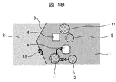
図1Bは、本発明の二相ステンレス鋼における脆化相形成抑制機構を示す概念図である。 FIG. 1B is a conceptual diagram showing an embrittlement phase formation suppression mechanism in the duplex stainless steel of the present invention.
本図の場合、タンタル原子11の方が金属間化合物形成元素5よりも空孔4を占有しやすいため、金属間化合物形成元素5の拡散が阻害される。これにより、粒界領域12に金属間化合物形成元素5の窒化物等が生じるのを防ぐことができる。
In the case of this figure, the
金属間化合物6は、σ相、χ相等で構成されており、α相/γ相界面を起点としてα相側に析出し易いことが知られている。金属間化合物6を構成する元素(金属間化合物形成元素5)であるCr、Mo、Si及びWは、金属母材中からα相/γ相界面の結晶粒界に濃縮し、金属間化合物6として析出する。そのため、これらの金属間化合物形成元素5の拡散速度を低減できれば、金属間化合物6の析出を遅延することができると考えられる。これらの元素のうち、Cr、Mo及びWは、ステンレス鋼を構成する元素の平均原子径に比べて大きな原子半径を有するオーバーサイズ元素であり、金属母材中の原子空孔(空孔4)との相互作用が強く、空孔4を優先的な拡散経路として移動するとされている。
It is known that the
このような現象があるため、これらの元素よりも原子半径が大きく、空孔4とより強く相互作用する元素を添加し、空孔4を添加元素にトラップさせ、金属間化合物形成元素5の拡散を阻害することが重要となる。これにより、特に、脆化相の析出が問題となる650℃〜950℃の温度域において金属間化合物形成元素5の拡散速度を低下させることができる。この温度域における脆化は、寸法の小さいステンレス鋼(鋼材)の場合、急冷することにより回避することができるが、寸法が大きく鋼材の内部を急冷することが困難な場合には問題となる。本発明は、この問題について鋼材の組成を調整することにより解決するものである。
Because of this phenomenon, an element having an atomic radius larger than these elements and an element that interacts more strongly with the
原子半径の大きな添加元素の候補としてはいくつか考えられるが、一般に、原子半径の大きい金属元素は、窒化物や炭化物を生成する自由エネルギーが極めて低い。 There are several possible addition elements with large atomic radii, but generally, metal elements with large atomic radii have extremely low free energy for generating nitrides and carbides.
熱平衡計算の結果、Zr、Ti、Hf等の窒・炭化物形成能が高い元素を添加した場合には、特に窒素を添加することにより耐食性を向上させているスーパー二相ステンレス鋼の場合には、製造時に液相の段階で窒化物を形成し、母相中への固溶が困難である。また、比較的窒化物形成能の低い元素のうち、Nbはそれ自体が金属間化合物であるσ相に取り込まれやすい元素であるとされている。 As a result of thermal equilibrium calculation, when an element having high nitrogen / carbide forming ability such as Zr, Ti, Hf is added, particularly in the case of super duplex stainless steel whose corrosion resistance is improved by adding nitrogen, Nitride is formed at the liquid phase stage during production, and it is difficult to form a solid solution in the matrix phase. Further, among the elements having relatively low nitride forming ability, Nb is an element that itself is easily incorporated into the σ phase that is an intermetallic compound.
以上のことから、製造時に金属母相中に固溶させる事が比較的容易で、かつ金属間化合物として析出し難い、Taを添加元素として選定した。 From the above, Ta was selected as an additional element, which is relatively easy to be dissolved in the metal matrix during production and hardly precipitates as an intermetallic compound.
以下では、本発明による二相ステンレス鋼に添加する合金元素の役割と化学組成範囲を限定する理由について説明する。 Below, the reason for limiting the role and chemical composition range of the alloy element added to the duplex stainless steel according to the present invention will be described.
クロム(Cr):20.0〜40.0%
クロムは、ステンレス鋼の耐食性の維持に最も重要な基本元素である。二相ステンレスの場合には、オーステナイトとフェライトの2相組織を得なければならないので、下記式で定義されるクロム当量(Creq)及びニッケル当量(Nieq)と、これにより決定されるフェライト相の比率(分率)とを考慮して、20%以上のクロム量とした。また、Creqを増加させるとNieqも増加させる必要があるため、経済性を考慮して上限値を40%とした。より好ましい範囲は24%〜26%である。Chromium (Cr): 20.0-40.0%
Chromium is the most important basic element for maintaining the corrosion resistance of stainless steel. In the case of duplex stainless steel, since a two-phase structure of austenite and ferrite must be obtained, the chromium equivalent (Cr eq ) and nickel equivalent (Ni eq ) defined by the following formulas, and the ferrite phase determined thereby The amount of chromium was set to 20% or more in consideration of the ratio (fraction). Further, if Cr eq is increased, Ni eq also needs to be increased, so the upper limit is set to 40% in consideration of economy. A more preferable range is 24% to 26%.
Creq=%Cr+2%Si+1.5%Mo+0.75%W+5%V+5.5%Al+1.75%Nb+1.5%Ti
Nieq=%Ni+0.5%Mn+30%C+0.3%Cu+25%N+%Co
(式中、%Cr、%Si、%Mo、%W、%V、%Al、%Nb、%Ti、%Ni、%Mn、%C、%Cu、%N及び%Coは、質量%で表した各組成の値である。)
フェライト相の分率(体積%)=55×(Creq/Nieq)−66.1
ニッケル(Ni):3.0%〜12.0%
ニッケルは、オーステナイト安定化元素として耐食性に関連して全面腐食抵抗性を増加させる有用な元素であるので、少なくとも3%以上とした。クロム当量とニッケル当量との関係、相の比率、及び経済性を考慮して、上限値を12%以下とした。より好ましい範囲は6%〜8%である。Cr eq =% Cr + 2% Si + 1.5% Mo + 0.75% W + 5% V + 5.5% Al + 1.75% Nb + 1.5% Ti
Ni eq =% Ni + 0.5% Mn + 30% C + 0.3% Cu + 25% N +% Co
(Wherein,% Cr,% Si,% Mo,% W,% V,% Al,% Nb,% Ti,% Ni,% Mn,% C,% Cu,% N and% Co are in mass%. It is the value of each composition expressed.)
Ferrite phase fraction (volume%) = 55 × (Cr eq / Ni eq ) −66.1
Nickel (Ni): 3.0% to 12.0%
Nickel is a useful element that increases the overall corrosion resistance in relation to the corrosion resistance as an austenite stabilizing element, so it was made at least 3% or more. In consideration of the relationship between the chromium equivalent and the nickel equivalent, the phase ratio, and the economy, the upper limit is set to 12% or less. A more preferable range is 6% to 8%.
モリブデン(Mo):7.0%以下
モリブデンは、クロムとともに、耐食性の維持に重要な元素であり、フェライト相を安定化させる作用をするが、添加により金属間化合物形成を促進する。このため、その量を7.0%以下に制限する。より好ましい範囲は3.0%〜5.0%である。Molybdenum (Mo): 7.0% or less Molybdenum, together with chromium, is an important element for maintaining corrosion resistance and acts to stabilize the ferrite phase, but the addition promotes the formation of intermetallic compounds. For this reason, the amount is limited to 7.0% or less. A more preferable range is 3.0% to 5.0%.
タングステン(W):6.5%以下
タングステンは、耐食性を向上させ、1/2の量のMoと置換することにより金属間化合物の析出速度を遅延させ、耐食性及び機械的性質を改善する元素である。しかし、タングステンは、高価な合金元素であり、また、多量に添加すると金属間化合物の生成を促進し、溶接部の耐食性を低下させるので、含有量を6.5%以下に制限する。より好ましい範囲は4.0%以下である。Tungsten (W): 6.5% or less Tungsten is an element that improves corrosion resistance, delays the precipitation rate of intermetallic compounds by substituting 1/2 of Mo, and improves corrosion resistance and mechanical properties. is there. However, tungsten is an expensive alloy element, and when added in a large amount, promotes the formation of intermetallic compounds and lowers the corrosion resistance of the welded portion, so the content is limited to 6.5% or less. A more preferable range is 4.0% or less.
ケイ素(Si):3.0%以下
ケイ素は、フェライト組織を安定化させる元素であり、製造時の脱酸に有効な元素である。また、製造時や溶接時の溶鋼の流動性を増加させて表面の欠陥を低減する元素である。しかしながら、金属間化合物の析出速度を増加させ、鋼の延性を低下させる元素であるため、3.0%以下が好ましい。より好ましくは、0.5%以下である。Silicon (Si): 3.0% or less Silicon is an element that stabilizes the ferrite structure, and is an element effective for deoxidation during production. Moreover, it is an element which increases the fluidity | liquidity of the molten steel at the time of manufacture and welding, and reduces the surface defect. However, since it is an element that increases the precipitation rate of intermetallic compounds and decreases the ductility of steel, 3.0% or less is preferable. More preferably, it is 0.5% or less.
マンガン(Mn):8.0%以下
マンガンは、高価なニッケルを代替することのできるオーステナイト安定化元素であり、窒素の固溶度を増加させ、高温の変形抵抗を増加させる元素である。特に、窒素を積極的に添加して耐食性を向上させようとする場合には、適正量のマンガン添加は必須である。溶解精錬時に脱酸効果を有するが、多量に添加すると耐食性が低下し、金属間化合物の生成を促進する。このため、その上限値を8%以下に制限した。より好ましい範囲は1.2%以下である。Manganese (Mn): 8.0% or less Manganese is an austenite stabilizing element that can replace expensive nickel, and is an element that increases the solid solubility of nitrogen and increases the deformation resistance at high temperature. In particular, when nitrogen is actively added to improve the corrosion resistance, it is essential to add an appropriate amount of manganese. Although it has a deoxidizing effect during melting and refining, if it is added in a large amount, the corrosion resistance is lowered and the formation of intermetallic compounds is promoted. For this reason, the upper limit was limited to 8% or less. A more preferable range is 1.2% or less.
窒素(N):0.7%以下
窒素は、孔食に対する抵抗性を向上させる有用な元素である。その効果は、クロムの約30倍に達する耐食性に関連して最も重要な元素の一つである。また、粒界鋭敏化を防止することを目的に炭素含有量を低くするとき、窒素を添加して強度を補填する。しかし、0.7%を超えて添加すると、製造時にブローホール発生により割れを生じることがある。よって、0.7%以下とすることが好ましい。特に、Taを添加する場合には、Taを含む窒化物を形成し、効果を阻害する。このため、α相とγ相とにバランスよく固溶し、耐食性を損なわないようにするためには、0.3%以下とすることが更に好ましく、0.05%〜0.25%とすることがより一層好ましい。さらに、0.05〜0.19%の範囲が特に望ましい。Nitrogen (N): 0.7% or less Nitrogen is a useful element that improves resistance to pitting corrosion. Its effect is one of the most important elements in relation to corrosion resistance, which is about 30 times that of chromium. In addition, when the carbon content is lowered for the purpose of preventing grain boundary sensitization, nitrogen is added to supplement the strength. However, if added over 0.7%, cracks may occur due to blowholes during production. Therefore, it is preferable to set it as 0.7% or less. In particular, when Ta is added, a nitride containing Ta is formed and the effect is hindered. For this reason, it is more preferable to set it as 0.3% or less, and it is 0.05%-0.25% in order not to impair corrosion resistance in the α-phase and γ-phase in a solid solution It is even more preferable. Furthermore, the range of 0.05 to 0.19% is particularly desirable.
炭素(C):0.1%以下
炭素は、炭化物を形成し、且つ溶接時の粒界鋭敏化を誘発する元素である。特に、Taを添加する場合には、Taを含む炭化物を形成し、Ta添加の効果を阻害するため、少ないほど好ましい。しかし、Cの低減は製造コストの上昇を招くため、0.1%以下とした。より好ましい範囲は0.02%以下である。Carbon (C): 0.1% or less Carbon is an element that forms carbides and induces grain boundary sensitization during welding. In particular, when Ta is added, it is preferable that the content is as small as possible because a carbide containing Ta is formed and the effect of Ta addition is inhibited. However, since the reduction of C causes an increase in manufacturing cost, it is set to 0.1% or less. A more preferable range is 0.02% or less.
タンタル(Ta):0.05%〜1.0%
タンタルは、本発明を特徴づける元素の一つである。前述したように、原子半径が二相ステンレス鋼を構成する元素の平均原子半径と比較して大きいため、主要な金属間化合物形成元素の拡散を阻止し、金属間化合物の析出速度を低下させる効果がある。しかしながら、添加量が多すぎると、経済的でないだけでなく、フェライト/オーステナイトの相比のバランスを崩すため、上限値を1.0%に制限した。一方、0.05%未満では、その添加効果は期待できない。また、窒化物相とフェライト相への固溶量のバランスから、より好ましくは0.2〜0.5%の範囲である。Tantalum (Ta): 0.05% to 1.0%
Tantalum is one of the elements that characterize the present invention. As mentioned above, the atomic radius is large compared to the average atomic radius of the elements that make up duplex stainless steel, which prevents the diffusion of the main intermetallic compound-forming elements and reduces the precipitation rate of intermetallic compounds. There is. However, if the addition amount is too large, not only is it not economical, but the upper limit value is limited to 1.0% in order to destroy the balance of the ferrite / austenite phase ratio. On the other hand, if it is less than 0.05%, the addition effect cannot be expected. Further, it is more preferably in the range of 0.2 to 0.5% from the balance of the solid solution amount in the nitride phase and the ferrite phase.
リン(P):0.1%以下
リンについては、鋼中に不可避に混入する不純物であり、耐食性を劣化するのみでなく粒界に偏析し、脆化相の析出を促進するため、少ないほど望ましい。このため、0.1%以下が望ましく、0.02%以下が更に望ましく、0.005%以下が特に望ましい。しかしながら、Pを過剰に低減する場合は製造コストの上昇を招く。よって、Pの添加量は、この点も考慮して決定する。Phosphorus (P): 0.1% or less Phosphorus is an impurity that is inevitably mixed in steel and not only deteriorates corrosion resistance but also segregates at grain boundaries and promotes precipitation of an embrittled phase. desirable. For this reason, 0.1% or less is desirable, 0.02% or less is more desirable, and 0.005% or less is particularly desirable. However, when P is excessively reduced, the manufacturing cost increases. Therefore, the addition amount of P is determined in consideration of this point.
以下、実施例を説明する。 Examples will be described below.
表1は、実施例1(発明材(作製材C))並びに比較例1及び2(比較材(作製材A及びB))の二相ステンレス鋼について化学組成(単位:質量%)を示したものである。 Table 1 shows the chemical composition (unit: mass%) of the duplex stainless steels of Example 1 (invention material (preparation material C)) and Comparative Examples 1 and 2 (comparative materials (preparation materials A and B)). Is.
これらの材料に製造時の冷却、及び溶接による再熱を模擬した熱処理を施し、比較した。 These materials were subjected to heat treatment simulating cooling during production and reheating by welding, and then compared.
表1に示す化学組成の二相ステンレス鋼をそれぞれ20kg、真空溶解炉で溶製してインゴットを得た。作製材Aは、規格材S32750と同等の成分を有する。作製材Bは、N、C及びSiの含有量を低減したものである。作製材Cは、作製材Bと同等の成分の合金に対してTaを微量添加したものである。 Ingots were obtained by melting 20 kg of duplex stainless steels having chemical compositions shown in Table 1 in a vacuum melting furnace. The preparation material A has the same components as the standard material S32750. The preparation material B has a reduced content of N, C and Si. The preparation material C is obtained by adding a small amount of Ta to an alloy having the same components as the preparation material B.
上記のインゴットを1250℃に加熱し、鍛造し、20×50×150(mm)の板材を得た。鍛造した板材は、適正なフェライト相/オーステナイト相の相比を得るため、1100℃×1時間で溶体化熱処理を実施したのち、脆化相の析出を避ける為、水冷で急冷した。 The ingot was heated to 1250 ° C. and forged to obtain a plate material of 20 × 50 × 150 (mm). The forged plate material was subjected to a solution heat treatment at 1100 ° C. for 1 hour in order to obtain an appropriate phase ratio of ferrite phase / austenite phase, and then quenched with water to avoid precipitation of the embrittled phase.
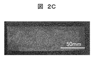
図2A、2B及び2Cはそれぞれ、鍛造した作製材A、B及びCの外観写真を示したものである。 2A, 2B, and 2C show appearance photographs of the forged materials A, B, and C, respectively.
これらの写真から、鍛造による割れや欠陥を生じることなく製造できていることがわかる。 From these photographs, it can be seen that the product can be produced without causing cracks or defects due to forging.
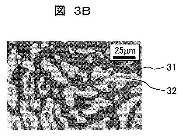
図3A、3B及び3Cはそれぞれ、製造後の作製材A、B及びCの金相観察結果を示したものである。 3A, 3B, and 3C show the observation results of the gold phases of the manufactured materials A, B, and C after manufacture, respectively.
金相観察においては、SiC研磨紙で2000番まで研磨し、1μmのダイヤモンド砥粒を用いて仕上げ研磨した後、10%NaOH水溶液を使用して電解エッチングを施した。これにより、フェライト相31は褐色に、金属間化合物、炭化物及び窒化物は黒色に着色される。また、オーステナイト相32は白色である。
In the gold phase observation, polishing was performed up to No. 2000 with SiC polishing paper, and final polishing was performed using 1 μm diamond abrasive grains, and then electrolytic etching was performed using a 10% NaOH aqueous solution. Thereby, the
試験片は、アセトン及び蒸留水を用いて超音波洗浄を施した後、光学顕微鏡で観察した。以降の金相観察も同様の方法で実施している。これらの図に示す金相観察の結果、いずれの作製材も明瞭に区別できるフェライト/オーステナイトの二相組織を有していることが分かる。 The test piece was subjected to ultrasonic cleaning using acetone and distilled water, and then observed with an optical microscope. Subsequent observation of the gold phase is carried out in the same way. As a result of the observation of the gold phase shown in these figures, it can be seen that each of the fabricated materials has a two-phase structure of ferrite / austenite that can be clearly distinguished.
上記の作製材に対して、製造時の冷却及び溶接による再熱条件における脆化相析出を評価するため、脆化相が析出しやすい温度域である800℃での熱処理を実施した。 In order to evaluate the embrittlement phase precipitation in the reheating conditions by cooling and welding at the time of manufacture, heat treatment was performed at 800 ° C., which is a temperature range in which the embrittlement phase is likely to precipitate.
図4は、800℃における熱処理時間と残存フェライト量との関係を示すグラフである。横軸に熱処理時間を、縦軸にフェライト量をとっている。フェライト量は、磁気誘導法を用いたフェライトスコープで測定した。脆化相析出のうち、金属間化合物析出は析出温度条件でフェライト相が金属間化合物相とオーステナイト相に分解することで進行するため、残存フェライト量を評価することにより金属間化合物の析出傾向を評価できる。 FIG. 4 is a graph showing the relationship between the heat treatment time at 800 ° C. and the amount of residual ferrite. The horizontal axis represents the heat treatment time, and the vertical axis represents the ferrite content. The amount of ferrite was measured with a ferrite scope using a magnetic induction method. Among the embrittlement phase precipitation, intermetallic compound precipitation proceeds by the decomposition of the ferrite phase into an intermetallic compound phase and an austenite phase at the precipitation temperature condition. Can be evaluated.
本図から、比較例1及び2と比べ、実施例1は、フェライト相の減少速度が遅く、フェライト相の分解が抑制されていることが分かる。 From this figure, it can be seen that, compared with Comparative Examples 1 and 2, Example 1 has a slower decrease rate of the ferrite phase and suppresses the decomposition of the ferrite phase.
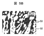
図5A、5B及び5Cはそれぞれ、800℃、30分の熱処理を施した後の作製材A、B及びCの金相観察写真である。 FIGS. 5A, 5B, and 5C are photographs of observation of the gold phase of the preparation materials A, B, and C after heat treatment at 800 ° C. for 30 minutes, respectively.
本図においては、フェライト相51及びオーステナイト相52に加え、脆化相53が増加していることがわかる。
In this figure, it can be seen that the
比較材である作製材A及びBと比べて、発明材である作製材Cにおいては、脆化相53の析出量が少なく、脆化相53の析出が抑制されていることが分かる。作製材Bは、脆化相53が特に多くなっている。
Compared with the preparation materials A and B which are comparative materials, in the preparation material C which is an invention material, the precipitation amount of the
図6は、800℃×5分の熱処理後におけるシャルピー衝撃値の測定結果を示したものである。 FIG. 6 shows the measurement result of the Charpy impact value after heat treatment at 800 ° C. for 5 minutes.
シャルピー衝撃値については、JIS Z2242(2005)に準拠して測定した。測定手順の概略は、次のとおりである。 The Charpy impact value was measured according to JIS Z2242 (2005). The outline of the measurement procedure is as follows.
熱処理前後の板材に対して、中心部がノッチ部となるように板の長手方向から10mm×10mm×55mmの2mmVノッチシャルピー試験片を採取し、衝撃値を測定した。 With respect to the plate material before and after the heat treatment, a 2 mm V notch Charpy test piece of 10 mm × 10 mm × 55 mm was taken from the longitudinal direction of the plate so that the center portion became a notch portion, and the impact value was measured.
本図から、比較材である作製材A及びBと比べて、発明材である作製材Cにおいては、熱処理後におけるシャルピー衝撃値が高くなっている。このことから、金属間化合物の形成抑制により靭性が改善していることがわかる。 From this figure, compared with the preparation materials A and B which are comparative materials, in the preparation material C which is an invention material, the Charpy impact value after heat treatment is high. This shows that the toughness is improved by suppressing the formation of intermetallic compounds.
図7A〜7Dは、800℃×1分の熱処理後の粒界(α/γ境界)におけるEDX測定の結果を示したものである。 7A to 7D show the results of EDX measurement at grain boundaries (α / γ boundary) after heat treatment at 800 ° C. for 1 minute.
図7Aは、比較材である作製材Aの電子顕微鏡写真であり、図7Bは、図7Aの分析位置(線分)における矢印方向の各元素の濃度分布を測定した結果を示したものである。 FIG. 7A is an electron micrograph of the preparation material A, which is a comparative material, and FIG. 7B shows the result of measuring the concentration distribution of each element in the arrow direction at the analysis position (line segment) in FIG. 7A. .
また、図7Cは、発明材である作製材Cの電子顕微鏡写真であり、図7Dは、図7Cの分析位置(線分)における矢印方向の各元素の濃度分布を測定した結果を示したものである。 Moreover, FIG. 7C is an electron micrograph of the preparation material C which is the invention material, and FIG. 7D shows the result of measuring the concentration distribution of each element in the arrow direction at the analysis position (line segment) in FIG. 7C. It is.
図7A及び7Cにおいては、フェライト相71及びオーステナイト相72の微細構造が明瞭に表されている。粒界は、破線で示している。線分で表した分析位置73においては、矢印の方向に(オーステナイト相72からフェライト相71に向かって)各元素の濃度測定を行った。
7A and 7C, the fine structure of the
図7B及び7Dにおいては、横軸に距離をとり、縦軸に濃度をとっている。 7B and 7D, the horizontal axis represents distance and the vertical axis represents density.
図7Bに示す比較材においては、フェライト相側の粒界の近傍におけるMo及びCrの濃度が高くなっている。 In the comparative material shown in FIG. 7B, the concentrations of Mo and Cr in the vicinity of the grain boundary on the ferrite phase side are high.
これに対して、図7Dに示す発明材においては、フェライト相側の粒界の近傍においてTaの濃度のピークが生じ、Mo及びCrの濃度は図7Bに比べて低くなっている。 In contrast, in the inventive material shown in FIG. 7D, a Ta concentration peak occurs in the vicinity of the grain boundary on the ferrite phase side, and the concentrations of Mo and Cr are lower than in FIG. 7B.
言い換えると、Taは、α/γ粒界に優先的に拡散し、金属間化合物形成元素であるMo及びCrの拡散を阻害していることがわかる。 In other words, it can be seen that Ta diffuses preferentially to the α / γ grain boundaries and inhibits the diffusion of Mo and Cr which are intermetallic compound forming elements.
以上より、Taを添加した場合、Ta自体が結晶粒界に拡散することにより、Mo、Cr等の金属間化合物形成元素の拡散を阻害し、金属間化合物の形成を遅延させることがわかった。 From the above, it has been found that when Ta is added, Ta itself diffuses into the grain boundary, thereby inhibiting the diffusion of intermetallic compound-forming elements such as Mo and Cr and delaying the formation of intermetallic compounds.
(残留応力及び衝撃値に熱処理が及ぼす影響)
残留応力緩和を目的とした溶接後熱処理(PWHT)を想定して、発明材及び比較材に熱処理を実施し、熱処理が残留応力及び衝撃値に及ぼす影響を評価した。(Effect of heat treatment on residual stress and impact value)
Assuming post-weld heat treatment (PWHT) for residual stress relaxation, the heat treatment was performed on the inventive material and the comparative material, and the influence of the heat treatment on the residual stress and impact value was evaluated.
作製材A、B及びCについて、粒度#46の砥石を用い、回転速度1440rpm、切り込み量0.01mmで板材表面に平面研削による強加工層を付与することにより、引張残留応力を付与した。平面研削により表面に残留応力を付与した供試材に対して、PWHTを想定して650℃×30分の熱処理を実施し、残留応力と機械的特性に及ぼす熱処理条件の影響を評価した。 About the preparation materials A, B, and C, using a grindstone of particle size # 46, a tensile working stress was imparted by imparting a strong working layer by surface grinding to the plate material surface at a rotational speed of 1440 rpm and a cutting depth of 0.01 mm. A test material having a residual stress applied to the surface by surface grinding was subjected to heat treatment at 650 ° C. for 30 minutes assuming PWHT, and the influence of the heat treatment conditions on the residual stress and mechanical properties was evaluated.
図8は、熱処理前後の残留応力を比較した結果を示したものである。残留応力をフェライト相、オーステナイト相それぞれで測定し、体積比を掛けた平均値をマクロ応力として評価した。 FIG. 8 shows the result of comparing the residual stress before and after the heat treatment. The residual stress was measured for each of the ferrite phase and austenite phase, and the average value multiplied by the volume ratio was evaluated as macro stress.
表面加工によって、900〜1100MPa程度の引張付応力が付与されていたが、650℃×30分の熱処理で何れも約200MPa程度の引張応力に低下し、8割程度の応力緩和効果が得られた。 By surface processing, a tensile stress of about 900 to 1100 MPa was applied, but the heat treatment at 650 ° C. × 30 minutes decreased to a tensile stress of about 200 MPa, and a stress relaxation effect of about 80% was obtained. .
図9は、熱処理前後のシャルピー衝撃試験の結果を比較した結果を示したものである。 FIG. 9 shows the result of comparing the results of the Charpy impact test before and after the heat treatment.
本図から、比較材に対して、発明材は、衝撃値が改善し、熱処理後も100J/cm2程度の衝撃値を残しており、650℃×30分の熱処理で残留応力を8割緩和しつつ、100J/cm2以上の衝撃値を保っている。From this figure, compared with the comparative material, the inventive material has improved impact value, and has left an impact value of about 100 J / cm 2 even after heat treatment, and the residual stress is reduced by 80% by heat treatment at 650 ° C. × 30 minutes. However, the impact value of 100 J / cm 2 or more is maintained.
(孔食発生電位に熱処理が及ぼす影響)
熱処理(650℃×30分)前後の孔食発生電位測定の結果を以下に示す。(Effect of heat treatment on pitting corrosion occurrence potential)
The results of pitting corrosion potential measurement before and after heat treatment (650 ° C. × 30 minutes) are shown below.
孔食電位については、JIS G0577(2005)に準拠して測定した。 The pitting corrosion potential was measured according to JIS G0577 (2005).
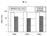
図10は、発明材と比較材の孔食発生電位を比較して示したものである。 FIG. 10 shows a comparison of the pitting corrosion occurrence potential of the inventive material and the comparative material.
本図に示すように、各材料の孔食抵抗性順位(熱処理後)は下記のとおりである。 As shown in this figure, the pitting corrosion resistance order (after heat treatment) of each material is as follows.
作製材C(発明材)>作製材B(比較材)>作製材A(比較材、従来材S32750相当)。 Fabrication material C (invention material)> Fabrication material B (comparative material)> Fabrication material A (comparative material, conventional material S32750 equivalent).
すなわち、発明材は、従来材より高い孔食発生電位を有する。 That is, the inventive material has a higher pitting corrosion potential than the conventional material.
以上の結果から、発明材は、脆化を抑制しているにもかかわらず、従来材以上の耐孔食性を有することが確認された。 From the above results, it was confirmed that the inventive material has pitting corrosion resistance higher than that of the conventional material, despite suppressing the embrittlement.
(発明材を用いた製品1)
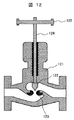
図11は、本発明に係る立軸斜流海水ポンプの断面図である。(
FIG. 11 is a cross-sectional view of a vertical axis mixed-flow seawater pump according to the present invention.
本図において、立軸斜流海水ポンプは、吸込水路から入った海水を整流するベルマウス117、原動機の回転動力を伝達するシャフト111、シャフト111に固定されたインペラハブ115、原動機の回転動力を効率良く海水に与えるインペラベーン113、インペラベーン113の外周の隙間が常に一定になるよう内側を球面にしたケーシングライナ114、インペラベーン113から海水に与えた速度エネルギーを圧力エネルギーに変換するケーシング112、加圧された海水が内部を通っていくコラムパイプ119、インペラキャップ116、コーン118などからなる。
In this figure, the vertical shaft mixed-flow seawater pump efficiently utilizes
ケーシングライナ114及びケーシング112は、各々、実施例1の鋳鋼で作製し、インペラハブ115及びインペラベーン113は、各々、実施例1の鍛造材で作製した。鋳造及び鍛造後、1100℃×1hの溶体化熱処理をし、その後、水冷し、フェライト量40〜50%の2相組成とした。その後、ケーシングライナ114とケーシング112との接合部、及びインペラハブ115とインペラベーン113との接合部をMIG溶接で接合し、バンドヒータを巻きつけ、溶接熱影響部を650℃まで昇温した後、その温度で30minの熱処理を実施し、急冷した。
The
X線残留応力測定により溶接熱影響部の残留応力を測定したところ、引張応力は80MPaまで低下していた。実施例1の鋼材を用いることにより、溶接部の靭性低下も抑制され、疲労強度も向上した使用寿命の長い海水ポンプを製作することできた。 When the residual stress in the weld heat affected zone was measured by X-ray residual stress measurement, the tensile stress was reduced to 80 MPa. By using the steel material of Example 1, it was possible to produce a seawater pump with a long service life in which a decrease in toughness of the welded portion was suppressed and fatigue strength was improved.
(発明材を用いた製品2)
図12は、本発明に係る流量調節弁の断面図である。(
FIG. 12 is a cross-sectional view of a flow control valve according to the present invention.
本図において、流量調節弁は、弁全体を支えるケーシング121、流量を調節する弁体122、弁体122が収まる弁座123、ハンドル125、ハンドル125の回転により弁体122の位置を調節するシャフト124などで構成されている。
In this figure, the flow rate adjusting valve includes a
ケーシング121を実施例1の鋳鋼によって構成した。実施例1の鋼材を用いることにより、耐食性が高く、大型の流量調節弁を製作することできた。
The
本流量調節弁は、海水、石油及び化学プラント環境で使用できる。 The flow control valve can be used in seawater, petroleum and chemical plant environments.
1:フェライト相、2:オーステナイト相、3:粒界、4:空孔、5:金属間化合物形成元素、6:金属間化合物、7:炭・窒化物、11:タンタル原子、12:粒界領域、31、51、71:フェライト相、32、52、72:オーステナイト相、53:脆化相、73:分析位置、111:シャフト、112:ケーシング、113:インペラベーン、114:ケーシングライナ、115:インペラハブ、116:インペラキャップ、117:ベルマウス、118:コーン、119:コラムパイプ、121:ケーシング、122:弁体、123:弁座、124:シャフト、125:ハンドル。
1: Ferrite phase, 2: Austenite phase, 3: Grain boundary, 4: Void, 5: Intermetallic compound forming element, 6: Intermetallic compound, 7: Carbon / nitride, 11: Tantalum atom, 12:
Claims (2)
N:0.05〜0.25%、
C:0.02%以下(Cは必須成分ではなく0%を含む)、
P:0.02%以下(Pは必須成分ではなく0%を含む)、
Si:0.5%以下(Siは必須成分ではなく0%を含む)、
Mn:1.2%以下(Mnは必須成分ではなく0%を含む)、
Ni:6.0〜8.0%、
Cr:24.0〜26.0%、
(Mo+0.5×W):3.0〜5.0%(但し、Mo:7.0%以下、W:6.5%以下の範囲であり、MoまたはWのいずれか一方が必須成分でなく、0%であっても良い)
Ta:0.2〜0.5%を含有し、残部がFe及び不可避的不純物であり、
下記式で定義される耐孔食指数(PREW)が40以上であることを特徴とする二相ステンレス鋼。
(PREW)=%Cr+3.3×(%Mo+0.5×%W)+30×%N
(式中、%Cr、%Mo、%W及び%Nは、質量%で表した各組成の値である。) % By mass
N: 0.05-0.25%
C: 0.02% or less (C is not an essential component but includes 0%),
P: 0.02% or less (P is not an essential component but includes 0%),
Si: 0.5% or less (Si is not an essential component but includes 0%),
Mn: 1.2% or less (Mn is not an essential component but includes 0%),
Ni: 6.0 to 8.0%,
Cr: 24.0 to 26.0%,
(Mo + 0.5 × W): 3.0 to 5.0% (However, Mo: 7.0% or less, W: 6.5% or less, and either Mo or W is an essential component. Not 0%)
Ta: contains 0.2 to 0.5%, the balance is Fe and inevitable impurities,
Pitting index defined by the following formula (PREW) is you characterized in that 40 or more duplex stainless steel.
(PREW) =% Cr + 3.3 × (% Mo + 0.5 ×% W) + 30 ×% N
(In the formula,% Cr,% Mo,% W and% N are values of each composition expressed in mass%.)
Applications Claiming Priority (1)
| Application Number | Priority Date | Filing Date | Title |
|---|---|---|---|
| PCT/JP2013/073038 WO2015029167A1 (en) | 2013-08-28 | 2013-08-28 | Duplex stainless steel, and duplex stainless steel structure, marine structure, petroleum/gas environment structure, pump impeller, pump casing, and flow adjustment valve body using same |
Publications (2)
| Publication Number | Publication Date |
|---|---|
| JPWO2015029167A1 JPWO2015029167A1 (en) | 2017-03-02 |
| JP6286435B2 true JP6286435B2 (en) | 2018-02-28 |
Family
ID=52585786
Family Applications (1)
| Application Number | Title | Priority Date | Filing Date |
|---|---|---|---|
| JP2015533851A Expired - Fee Related JP6286435B2 (en) | 2013-08-28 | 2013-08-28 | Duplex stainless steel and duplex stainless steel structure using the same |
Country Status (4)
| Country | Link |
|---|---|
| EP (1) | EP3040434B1 (en) |
| JP (1) | JP6286435B2 (en) |
| CN (1) | CN105492641A (en) |
| WO (1) | WO2015029167A1 (en) |
Families Citing this family (6)
| Publication number | Priority date | Publication date | Assignee | Title |
|---|---|---|---|---|
| JP6482074B2 (en) * | 2014-09-02 | 2019-03-13 | 日本冶金工業株式会社 | Duplex stainless steel sheet and its manufacturing method |
| JP6686320B2 (en) * | 2015-08-05 | 2020-04-22 | 日本製鉄株式会社 | Manufacturing method of stainless steel pipe |
| CN107312979A (en) * | 2016-04-26 | 2017-11-03 | 天津碧宇舟机械制造有限公司 | A kind of high-power corrosion-resistant blade wheel of slurry pump and its manufacture method |
| CN107312951A (en) * | 2016-04-26 | 2017-11-03 | 天津碧宇舟机械制造有限公司 | A kind of homogenizer highly stressed rotor and preparation method thereof |
| CN105755397B (en) * | 2016-05-24 | 2017-07-07 | 江苏金基特钢有限公司 | The processing method that a kind of corrosion-resistant easy is molded special steel |
| SE1950909A1 (en) | 2019-07-31 | 2021-02-01 | Ferritico Ab | Duplex steel with improved embrittlement properties and method of producing such |
Family Cites Families (7)
| Publication number | Priority date | Publication date | Assignee | Title |
|---|---|---|---|---|
| US4055448A (en) * | 1973-04-10 | 1977-10-25 | Daido Seiko Kabushiki Kaisha | Ferrite-austenite stainless steel |
| JPS5441214A (en) * | 1977-09-08 | 1979-04-02 | Nippon Yakin Kogyo Co Ltd | Twoophase highhstrength stainless steel |
| DE19628350B4 (en) * | 1996-07-13 | 2004-04-15 | Schmidt & Clemens Gmbh & Co | Use of a stainless ferritic-austenitic steel alloy |
| JP4031992B2 (en) * | 2001-04-27 | 2008-01-09 | リサーチ インスティチュート オブ インダストリアル サイエンス アンド テクノロジー | High manganese duplex stainless steel with excellent hot workability and method for producing the same |
| KR100460346B1 (en) | 2002-03-25 | 2004-12-08 | 이인성 | Super duplex stainless steel with a suppressed formation of intermetallic phases and having an excellent corrosion resistance, embrittlement resistance, castability and hot workability |
| CA2826880C (en) * | 2011-02-14 | 2017-07-25 | Nippon Steel & Sumitomo Metal Corporation | Duplex stainless steel and production method therefor |
| JP5890330B2 (en) * | 2013-01-15 | 2016-03-22 | 株式会社神戸製鋼所 | Duplex stainless steel and duplex stainless steel pipe |
-
2013
- 2013-08-28 JP JP2015533851A patent/JP6286435B2/en not_active Expired - Fee Related
- 2013-08-28 EP EP13892680.3A patent/EP3040434B1/en not_active Expired - Fee Related
- 2013-08-28 WO PCT/JP2013/073038 patent/WO2015029167A1/en active Application Filing
- 2013-08-28 CN CN201380079140.6A patent/CN105492641A/en active Pending
Also Published As
| Publication number | Publication date |
|---|---|
| EP3040434A4 (en) | 2017-05-03 |
| JPWO2015029167A1 (en) | 2017-03-02 |
| EP3040434A1 (en) | 2016-07-06 |
| WO2015029167A1 (en) | 2015-03-05 |
| CN105492641A (en) | 2016-04-13 |
| EP3040434B1 (en) | 2019-03-27 |
Similar Documents
| Publication | Publication Date | Title |
|---|---|---|
| JP6286435B2 (en) | Duplex stainless steel and duplex stainless steel structure using the same | |
| JP6540922B1 (en) | Martensitic stainless steel seamless steel pipe for oil well pipe and method for producing the same | |
| JP6393993B2 (en) | Ni-base superalloy with high temperature strength and capable of hot forging | |
| JP6645103B2 (en) | High Mn steel material and method for producing the same | |
| JP2005336595A (en) | High strength stainless steel pipe excellent in corrosion resistance for use in oil well and method for production thereof | |
| JP2019039073A (en) | Duplex ferritic austenitic stainless steel | |
| JP5863770B2 (en) | Austenitic cast stainless steel | |
| JP5890330B2 (en) | Duplex stainless steel and duplex stainless steel pipe | |
| JP5137934B2 (en) | Ferritic heat resistant steel | |
| JP2014043616A (en) | Duplex stainless steel, and manufacturing method thereof | |
| JP6816779B2 (en) | Austenitic heat-resistant alloy member and its manufacturing method | |
| JP2017166019A (en) | Low alloy seamless steel tube for high intensity oil well and manufacturing method therefor | |
| JP2010280950A (en) | Heat resistant steel for exhaust valve and method for producing the same | |
| JP2010150585A (en) | Ni-based alloy for casting part of steam turbine excellent in high-temperature strength, castability and weldability, turbine casing of steam turbine, valve casing of steam turbine, nozzle box of steam turbine, and pipe of steam turbine | |
| JP6733211B2 (en) | Ni-based superalloy for hot forging | |
| JP5578916B2 (en) | Ni-based alloy for cast components of steam turbine and cast components of steam turbine | |
| JP2005325388A (en) | Low specific gravity iron alloy | |
| JP6602462B2 (en) | Chromium-based two-phase alloy and product using the two-phase alloy | |
| JP2019183193A (en) | Austenite stainless steel | |
| JP2017179478A (en) | Austenitic heat resistant alloy member and manufacturing method therefor | |
| JP3848463B2 (en) | High strength austenitic heat resistant steel with excellent weldability and method for producing the same | |
| GB2368849A (en) | Martensitic stainless steel | |
| JP6201731B2 (en) | Austenitic heat-resistant casting alloy | |
| JP2020015925A (en) | Cr-BASED TWO-PHASE ALLOY MANUFACTURED ARTICLE AND MANUFACTURING METHOD THEREFOR | |
| JP2005325387A (en) | Low specific gravity iron alloy |
Legal Events
| Date | Code | Title | Description |
|---|---|---|---|
| A131 | Notification of reasons for refusal |
Free format text: JAPANESE INTERMEDIATE CODE: A131 Effective date: 20161227 |
|
| RD04 | Notification of resignation of power of attorney |
Free format text: JAPANESE INTERMEDIATE CODE: A7424 Effective date: 20170111 |
|
| RD04 | Notification of resignation of power of attorney |
Free format text: JAPANESE INTERMEDIATE CODE: A7424 Effective date: 20170113 |
|
| A521 | Request for written amendment filed |
Free format text: JAPANESE INTERMEDIATE CODE: A523 Effective date: 20170201 |
|
| A131 | Notification of reasons for refusal |
Free format text: JAPANESE INTERMEDIATE CODE: A131 Effective date: 20170711 |
|
| A521 | Request for written amendment filed |
Free format text: JAPANESE INTERMEDIATE CODE: A523 Effective date: 20170831 |
|
| TRDD | Decision of grant or rejection written | ||
| A01 | Written decision to grant a patent or to grant a registration (utility model) |
Free format text: JAPANESE INTERMEDIATE CODE: A01 Effective date: 20180109 |
|
| A61 | First payment of annual fees (during grant procedure) |
Free format text: JAPANESE INTERMEDIATE CODE: A61 Effective date: 20180205 |
|
| R150 | Certificate of patent or registration of utility model |
Ref document number: 6286435 Country of ref document: JP Free format text: JAPANESE INTERMEDIATE CODE: R150 |
|
| LAPS | Cancellation because of no payment of annual fees |