JP6285958B2 - Stereo support with rolling shutter - Google Patents
Stereo support with rolling shutter Download PDFInfo
- Publication number
- JP6285958B2 JP6285958B2 JP2015552164A JP2015552164A JP6285958B2 JP 6285958 B2 JP6285958 B2 JP 6285958B2 JP 2015552164 A JP2015552164 A JP 2015552164A JP 2015552164 A JP2015552164 A JP 2015552164A JP 6285958 B2 JP6285958 B2 JP 6285958B2
- Authority
- JP
- Japan
- Prior art keywords
- image
- capture device
- image capture
- view
- field
- Prior art date
- Legal status (The legal status is an assumption and is not a legal conclusion. Google has not performed a legal analysis and makes no representation as to the accuracy of the status listed.)
- Active
Links
- 238000005096 rolling process Methods 0.000 title claims description 41
- 230000001360 synchronised effect Effects 0.000 claims description 89
- 238000000034 method Methods 0.000 claims description 32
- 238000012545 processing Methods 0.000 claims description 27
- 238000003384 imaging method Methods 0.000 claims description 16
- 230000000737 periodic effect Effects 0.000 claims 2
- 230000000875 corresponding effect Effects 0.000 description 28
- 238000006073 displacement reaction Methods 0.000 description 24
- 230000008569 process Effects 0.000 description 14
- 230000006870 function Effects 0.000 description 11
- 230000003287 optical effect Effects 0.000 description 10
- 238000012937 correction Methods 0.000 description 9
- 239000011159 matrix material Substances 0.000 description 9
- 230000003068 static effect Effects 0.000 description 6
- 230000001419 dependent effect Effects 0.000 description 4
- 238000001514 detection method Methods 0.000 description 4
- 238000005259 measurement Methods 0.000 description 4
- 230000004048 modification Effects 0.000 description 4
- 238000012986 modification Methods 0.000 description 4
- 238000013459 approach Methods 0.000 description 3
- 238000004364 calculation method Methods 0.000 description 3
- 230000006978 adaptation Effects 0.000 description 2
- 230000008859 change Effects 0.000 description 2
- 230000007423 decrease Effects 0.000 description 2
- 230000010354 integration Effects 0.000 description 2
- 238000007781 pre-processing Methods 0.000 description 2
- 238000009966 trimming Methods 0.000 description 2
- 230000003466 anti-cipated effect Effects 0.000 description 1
- 230000006835 compression Effects 0.000 description 1
- 238000007906 compression Methods 0.000 description 1
- 230000002596 correlated effect Effects 0.000 description 1
- 238000012888 cubic function Methods 0.000 description 1
- 230000001351 cycling effect Effects 0.000 description 1
- 230000001934 delay Effects 0.000 description 1
- 230000003111 delayed effect Effects 0.000 description 1
- 238000009499 grossing Methods 0.000 description 1
- 238000013507 mapping Methods 0.000 description 1
- 238000003909 pattern recognition Methods 0.000 description 1
- 238000000926 separation method Methods 0.000 description 1
- 238000004088 simulation Methods 0.000 description 1
- 230000009466 transformation Effects 0.000 description 1
- 230000007704 transition Effects 0.000 description 1
- 238000010200 validation analysis Methods 0.000 description 1
Images


Classifications
-
- H—ELECTRICITY
- H04—ELECTRIC COMMUNICATION TECHNIQUE
- H04N—PICTORIAL COMMUNICATION, e.g. TELEVISION
- H04N13/00—Stereoscopic video systems; Multi-view video systems; Details thereof
- H04N13/20—Image signal generators
- H04N13/204—Image signal generators using stereoscopic image cameras
- H04N13/25—Image signal generators using stereoscopic image cameras using two or more image sensors with different characteristics other than in their location or field of view, e.g. having different resolutions or colour pickup characteristics; using image signals from one sensor to control the characteristics of another sensor
-
- H—ELECTRICITY
- H04—ELECTRIC COMMUNICATION TECHNIQUE
- H04N—PICTORIAL COMMUNICATION, e.g. TELEVISION
- H04N25/00—Circuitry of solid-state image sensors [SSIS]; Control thereof
- H04N25/50—Control of the SSIS exposure
- H04N25/53—Control of the integration time
- H04N25/531—Control of the integration time by controlling rolling shutters in CMOS SSIS
-
- G—PHYSICS
- G06—COMPUTING; CALCULATING OR COUNTING
- G06V—IMAGE OR VIDEO RECOGNITION OR UNDERSTANDING
- G06V20/00—Scenes; Scene-specific elements
- G06V20/50—Context or environment of the image
- G06V20/56—Context or environment of the image exterior to a vehicle by using sensors mounted on the vehicle
-
- H—ELECTRICITY
- H04—ELECTRIC COMMUNICATION TECHNIQUE
- H04N—PICTORIAL COMMUNICATION, e.g. TELEVISION
- H04N13/00—Stereoscopic video systems; Multi-view video systems; Details thereof
- H04N13/20—Image signal generators
- H04N13/282—Image signal generators for generating image signals corresponding to three or more geometrical viewpoints, e.g. multi-view systems
-
- H—ELECTRICITY
- H04—ELECTRIC COMMUNICATION TECHNIQUE
- H04N—PICTORIAL COMMUNICATION, e.g. TELEVISION
- H04N13/00—Stereoscopic video systems; Multi-view video systems; Details thereof
- H04N13/20—Image signal generators
- H04N13/296—Synchronisation thereof; Control thereof
-
- H—ELECTRICITY
- H04—ELECTRIC COMMUNICATION TECHNIQUE
- H04N—PICTORIAL COMMUNICATION, e.g. TELEVISION
- H04N23/00—Cameras or camera modules comprising electronic image sensors; Control thereof
- H04N23/60—Control of cameras or camera modules
-
- H—ELECTRICITY
- H04—ELECTRIC COMMUNICATION TECHNIQUE
- H04N—PICTORIAL COMMUNICATION, e.g. TELEVISION
- H04N23/00—Cameras or camera modules comprising electronic image sensors; Control thereof
- H04N23/60—Control of cameras or camera modules
- H04N23/69—Control of means for changing angle of the field of view, e.g. optical zoom objectives or electronic zooming
-
- H—ELECTRICITY
- H04—ELECTRIC COMMUNICATION TECHNIQUE
- H04N—PICTORIAL COMMUNICATION, e.g. TELEVISION
- H04N23/00—Cameras or camera modules comprising electronic image sensors; Control thereof
- H04N23/90—Arrangement of cameras or camera modules, e.g. multiple cameras in TV studios or sports stadiums
-
- H—ELECTRICITY
- H04—ELECTRIC COMMUNICATION TECHNIQUE
- H04N—PICTORIAL COMMUNICATION, e.g. TELEVISION
- H04N5/00—Details of television systems
- H04N5/04—Synchronising
-
- B—PERFORMING OPERATIONS; TRANSPORTING
- B60—VEHICLES IN GENERAL
- B60R—VEHICLES, VEHICLE FITTINGS, OR VEHICLE PARTS, NOT OTHERWISE PROVIDED FOR
- B60R2300/00—Details of viewing arrangements using cameras and displays, specially adapted for use in a vehicle
- B60R2300/10—Details of viewing arrangements using cameras and displays, specially adapted for use in a vehicle characterised by the type of camera system used
- B60R2300/105—Details of viewing arrangements using cameras and displays, specially adapted for use in a vehicle characterised by the type of camera system used using multiple cameras
-
- B—PERFORMING OPERATIONS; TRANSPORTING
- B60—VEHICLES IN GENERAL
- B60R—VEHICLES, VEHICLE FITTINGS, OR VEHICLE PARTS, NOT OTHERWISE PROVIDED FOR
- B60R2300/00—Details of viewing arrangements using cameras and displays, specially adapted for use in a vehicle
- B60R2300/30—Details of viewing arrangements using cameras and displays, specially adapted for use in a vehicle characterised by the type of image processing
- B60R2300/303—Details of viewing arrangements using cameras and displays, specially adapted for use in a vehicle characterised by the type of image processing using joined images, e.g. multiple camera images
-
- B—PERFORMING OPERATIONS; TRANSPORTING
- B60—VEHICLES IN GENERAL
- B60R—VEHICLES, VEHICLE FITTINGS, OR VEHICLE PARTS, NOT OTHERWISE PROVIDED FOR
- B60R2300/00—Details of viewing arrangements using cameras and displays, specially adapted for use in a vehicle
- B60R2300/80—Details of viewing arrangements using cameras and displays, specially adapted for use in a vehicle characterised by the intended use of the viewing arrangement
- B60R2300/8093—Details of viewing arrangements using cameras and displays, specially adapted for use in a vehicle characterised by the intended use of the viewing arrangement for obstacle warning
Description
本願は、2013年1月15日に出願された米国仮特許出願第61/752,515号、及び2013年2月7日に出願された米国仮特許出願第61/761,724号の優先権を米国特許法第119条の下で主張する。上記の各出願は、参照によりその全体を本明細書に援用する。 This application is a priority of US Provisional Patent Application No. 61 / 752,515, filed on January 15, 2013, and US Provisional Patent Application No. 61 / 761,724, filed on February 7, 2013. Is claimed under 35 USC 119. Each of the above applications is incorporated herein by reference in its entirety.
背景
I.技術分野
本開示は一般に、カメラ撮像システムに関し、より詳細にはローリングシャッターによって画像を捕捉するための装置及び技法、車両に含めることができるステレオ画像取得システムに関する。
Background I. TECHNICAL FIELD The present disclosure relates generally to camera imaging systems, and more particularly to apparatus and techniques for capturing images with a rolling shutter, and a stereo image acquisition system that can be included in a vehicle.
II.背景情報
カメラによる車両用の運転手支援システムは、画像を集めるために単一のカメラに主に依存する単眼物体検出システムを含み得る。この種のシステム内の画像は単一視点から捕捉されるので、対象物までの距離を直接求めることが困難であり得る。従って、単眼対象物検出システムは、物体クラスに関する情報及び/又は物体のコンテキスト(例えば対象物がその上にある路面の様相)に関連するコンテキスト情報に基づいて対象物までの距離を間接的に求めるために推定技法を用いる場合がある。場合によっては、単眼システムは、単眼距離推定の前に特定の物体クラスを検出するために、パターン認識を使用することができる。
II. Background Information Camera driver assistance systems for vehicles may include monocular object detection systems that rely primarily on a single camera to collect images. Since images in this type of system are captured from a single viewpoint, it may be difficult to directly determine the distance to the object. Accordingly, the monocular object detection system indirectly determines the distance to the object based on information related to the object class and / or context information related to the context of the object (eg, the appearance of the road surface on which the object is located). Therefore, an estimation technique may be used. In some cases, the monocular system can use pattern recognition to detect a specific object class prior to monocular distance estimation.
カメラによる車両用の運転手支援システムは、2台のカメラを使用するステレオシステムも含み得る。一部のシステムでは、これらのカメラを並列に装着することができ、エピポーラ線が水平な画像走査線に対して位置合わせされる。かかるシステムは、高密度視差マップを使用して環境の3Dマップを作成することができる。次いでシステムは、例えば更に処理するための候補領域を見つけるために、その3D表現を前景及び/又は背景分離に使用することができる。システムは、興味をそそる物体の位置を突き止めるために、又は検出された物体までの距離及び/若しくは距離レートを推定するためにも3D表現を使用することができる。かかるステレオシステムは、近距離又は中距離の対象及び良い天気では上手く機能することができ、全体的な対象に関する奥行マップを与え得る。しかし、かかるステレオシステムは、悪天候の間又は雑然としたシーンが存在する場合に困難に直面する場合がある。更に、これらのシステムは、車両からより離れた距離にある物体を撮像するのが困難であり得る。 A camera driver assistance system for a vehicle may also include a stereo system using two cameras. In some systems, these cameras can be mounted in parallel, with the epipolar lines aligned with the horizontal image scan lines. Such a system can create a 3D map of the environment using a high density parallax map. The system can then use the 3D representation for foreground and / or background separation, eg, to find candidate regions for further processing. The system can also use the 3D representation to locate the object of interest or to estimate the distance and / or distance rate to the detected object. Such a stereo system can work well for short or medium distance objects and good weather, and can provide a depth map for the overall object. However, such stereo systems may face difficulties during bad weather or when there are cluttered scenes. Furthermore, these systems can be difficult to image objects at a greater distance from the vehicle.
米国特許第7,786,898号に記載のシステム等、一部の撮像システムは、単眼システム及びステレオシステムの両方からの情報を融合させることができる。この種のシステムは、対象を検出/選択し、距離を推定する役割を担う一次カメラを含み得る。対象を検証するために、二次カメラが被選択対象に対するステレオ距離を提供し得る。 Some imaging systems, such as the system described in US Pat. No. 7,786,898, can fuse information from both monocular and stereo systems. This type of system may include a primary camera that is responsible for detecting / selecting objects and estimating distance. In order to verify the object, a secondary camera may provide a stereo distance to the selected object.
一部のステレオシステムは、ステレオ奥行と単眼奥行とを組み合わせることができる非対称構成を含み得る。例えば、2台の非対称カメラ(例えば異なる視野(FOV)及び焦点距離を有する)を独立した用途で使用することができる。更に、それらのカメラからの画像情報を組み合わせてステレオ奥行をもたらすことができる。グローバルシャッターを有するカメラでは、かかるステレオ処理は、マッチする画像の対を提供するために、とりわけより広いFOVのカメラをトリミングすること、画像を平滑化しサブサンプリングすること、及び/又は修正することを含み得る。 Some stereo systems may include an asymmetric configuration that can combine stereo depth and monocular depth. For example, two asymmetric cameras (eg, having different fields of view (FOV) and focal lengths) can be used in independent applications. In addition, the image information from those cameras can be combined to provide stereo depth. For cameras with global shutters, such stereo processing includes, among other things, trimming wider FOV cameras, smoothing and subsampling and / or modifying images to provide matching image pairs. May be included.
自動車センサに使用され得る画像センサを含む最近の世代の画像センサは、ローリングシャッターを含み得る。かかるローリングシャッターは、特に異なる視野を有するカメラを用いる非対称ステレオ応用において、ステレオ画像処理に複雑さを生ぜしめる場合がある。例えば、ワイドFOVカメラ及びナローFOVカメラの両方が共通のシーンを狙う場合、ナローFOVカメラがワイドFOVカメラのFOVの一部としか重複しない場合がある。同様の線走査速度で取得されるほぼ同数の画像走査線として両方のカメラが画像を取得する場合、2台のカメラの視野内の重複領域内の取得済みの画像走査線は同期しなくなる。かかる同期の欠如は、ナローFOVカメラからの第2の画像内の画像点に対する、ワイドFOVカメラからの第1の画像内の画像点の相関関係を求める際に問題を引き起こす場合があり、このことは物体距離測定で著しい不正確さにつながり得る。 Recent generations of image sensors, including image sensors that can be used in automotive sensors, can include rolling shutters. Such rolling shutters can add complexity to stereo image processing, especially in asymmetric stereo applications using cameras with different fields of view. For example, when both a wide FOV camera and a narrow FOV camera aim at a common scene, the narrow FOV camera may overlap only with a part of the FOV of the wide FOV camera. If both cameras acquire images as approximately the same number of image scan lines acquired at similar line scan speeds, the acquired image scan lines in the overlap region within the field of view of the two cameras will not be synchronized. This lack of synchronization can cause problems in determining the correlation of the image points in the first image from the wide FOV camera to the image points in the second image from the narrow FOV camera. Can lead to significant inaccuracies in object distance measurements.
概要
開示する実施形態に従い、車両用の撮像システムが提供され、このシステムは、第1の視野を有し、車両に関連するシーンに関する第1の画像を取得するように構成される第1の画像捕捉装置を含み、第1の画像は、ローリングシャッターを使用して捕捉される第1の一連の画像走査線として取得される。この撮像システムは、第1の視野とは異なり、第1の視野と少なくとも部分的に重複する第2の視野を有する第2の画像捕捉装置も含むことができ、第2の画像捕捉装置は、車両に関連するシーンに関する第2の画像を取得するように構成され、第2の画像は、ローリングシャッターを使用して捕捉される第2の一連の画像走査線として取得される。第1の視野と第2の視野とが重複する結果、第1の画像の第1の重複部分が、第2の画像の第2の重複部分に対応し得る。第1の画像捕捉装置は、第2の一連の画像走査線の取得に関連する第2の走査速度とは異なり得る第1の一連の画像走査線の取得に関連する第1の走査速度を有することができ、その結果、第1の画像捕捉装置は第1の画像の第1の重複部分を、第2の画像の第2の重複部分が取得される期間にわたって取得する。
In accordance with disclosed embodiments, an imaging system for a vehicle is provided, the system having a first field of view and configured to obtain a first image relating to a scene associated with the vehicle. A capture device is included, and the first image is acquired as a first series of image scan lines that are captured using a rolling shutter. The imaging system may also include a second image capture device having a second field of view that, unlike the first field of view, at least partially overlaps the first field of view, the second image capture device comprising: A second image relating to a scene associated with the vehicle is acquired, and the second image is acquired as a second series of image scan lines captured using a rolling shutter. As a result of the overlap of the first field of view and the second field of view, the first overlapping portion of the first image may correspond to the second overlapping portion of the second image. The first image capture device has a first scan speed associated with acquiring a first series of image scan lines that may be different from a second scan speed associated with acquiring a second series of image scan lines. As a result, the first image capture device acquires the first overlap portion of the first image over a period of time during which the second overlap portion of the second image is acquired.
開示する実施形態に従い、車両を開示し、この車両は車体及び車両用の撮像システムを含み、そのシステムは、第1の視野を有し、車両に関連するシーンに関する第1の画像を取得するように構成される第1の画像捕捉装置を含み、第1の画像は、ローリングシャッターを使用して捕捉される第1の一連の画像走査線として取得される。この撮像システムは、第1の視野とは異なり、第1の視野と少なくとも部分的に重複する第2の視野を有する第2の画像捕捉装置も含むことができ、第2の画像捕捉装置は、車両に関連するシーンに関する第2の画像を取得するように構成され、第2の画像は、ローリングシャッターを使用して捕捉される第2の一連の画像走査線として取得される。第1の視野と第2の視野とが重複する結果、第1の画像の第1の重複部分が、第2の画像の第2の重複部分に対応し得る。第1の画像捕捉装置は、第2の一連の画像走査線の取得に関連する第2の走査速度とは異なり得る第1の一連の画像走査線の取得に関連する第1の走査速度を有することができ、その結果、第1の画像捕捉装置は第1の画像の第1の重複部分を、第2の画像の第2の重複部分が取得される期間にわたって取得し、その期間は第1の走査速度と第2の走査速度との比率に関連する。 In accordance with the disclosed embodiments, a vehicle is disclosed that includes a vehicle body and an imaging system for the vehicle, the system having a first field of view and acquiring a first image relating to a scene associated with the vehicle. The first image is acquired as a first series of image scan lines that are captured using a rolling shutter. The imaging system may also include a second image capture device having a second field of view that, unlike the first field of view, at least partially overlaps the first field of view, the second image capture device comprising: A second image relating to a scene associated with the vehicle is acquired, and the second image is acquired as a second series of image scan lines captured using a rolling shutter. As a result of the overlap of the first field of view and the second field of view, the first overlapping portion of the first image may correspond to the second overlapping portion of the second image. The first image capture device has a first scan speed associated with acquiring a first series of image scan lines that may be different from a second scan speed associated with acquiring a second series of image scan lines. As a result, the first image capture device acquires a first overlap of the first image over a period of time during which the second overlap of the second image is acquired, the period being the first Is related to the ratio of the scanning speed to the second scanning speed.
開示する実施形態に従い、車両用の撮像システムが提供され、このシステムは、第1の視野を有し、車両に関連するシーンに関する第1の画像を取得するように構成される第1の画像捕捉装置を含み、第1の画像は、ローリングシャッターを使用して捕捉される第1の一連の画像走査線として取得される。このシステムは、第1の視野とは異なり、第1の視野と少なくとも部分的に重複する第2の視野を有する第2の画像捕捉装置も含むことができ、第2の画像捕捉装置は、車両に関連するシーンに関する第2の画像を取得するように構成され、第2の画像は、ローリングシャッターを使用して捕捉される第2の一連の画像走査線として取得される。第1の視野と第2の視野とが重複する結果、第1の画像の第1の重複部分が、第2の画像の第2の重複部分に対応し得る。システムは、第1の画像捕捉装置から第1の画像を受け取り、第2の画像捕捉装置から第2の画像を受け取り、第1の画像の第1の重複部分の少なくとも第1の領域を、第2の画像の第2の重複部分の対応する第2の領域に相関させるように構成される少なくとも1個の処理装置を含むことができる。 In accordance with the disclosed embodiments, an imaging system for a vehicle is provided, the system having a first field of view and configured to acquire a first image relating to a scene associated with the vehicle. A first image is acquired as a first series of image scan lines captured using a rolling shutter. The system may also include a second image capture device having a second field of view that differs from the first field of view and at least partially overlaps the first field of view, the second image capture device comprising: Is acquired as a second series of image scan lines that are captured using a rolling shutter. As a result of the overlap of the first field of view and the second field of view, the first overlapping portion of the first image may correspond to the second overlapping portion of the second image. The system receives a first image from a first image capture device, receives a second image from a second image capture device, and at least a first region of a first overlap portion of the first image, At least one processing device configured to correlate to a corresponding second region of the second overlapping portion of the two images may be included.
上記の全般的な説明及び以下の詳細な説明はどちらも例示的及び説明的に過ぎず、特許請求の範囲を限定しないことを理解すべきである。 It should be understood that both the foregoing general description and the following detailed description are exemplary and explanatory only and do not limit the scope of the claims.
図面の簡単な説明
本開示に組み込まれ、本開示の一部を成す添付図面は、開示される様々な実施形態を示す。
BRIEF DESCRIPTION OF THE DRAWINGS The accompanying drawings, which are incorporated in and constitute a part of this disclosure, illustrate various disclosed embodiments.
詳細な説明
以下の詳細な説明は添付図面を参照する。可能な限り、図面及び以下の説明の中で同じ参照番号を使用して同じ又は同様の部分を指す。幾つかの例示的実施形態を本明細書に記載するが、修正形態、適合形態、及び他の実装形態が可能である。例えば、図中に示す構成要素に置換、追加、又は修正を加えることができ、開示する方法についてステップを置換し、並べ替え、除去し、又は追加することにより、本明細書に記載の例示的方法を修正することができる。従って、以下の詳細な説明は、開示する実施形態を限定するものではない。むしろ、適切な範囲は添付の特許請求の範囲によって定められる。
DETAILED DESCRIPTION The following detailed description refers to the accompanying drawings. Wherever possible, the same reference numbers are used in the drawings and the following description to refer to the same or like parts. While some exemplary embodiments are described herein, modifications, adaptations, and other implementations are possible. For example, the components shown in the figures can be replaced, added, or modified, and the exemplary methods described herein can be substituted, rearranged, removed, or added for the disclosed methods. The method can be modified. Accordingly, the following detailed description does not limit the disclosed embodiments. Rather, the proper scope is defined by the appended claims.
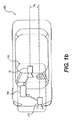
添付図面を参照し、図1aは、ここで開示するものに従う、例示的車両撮像システムの概略的な側面図の描写である。図1bは、図1aに示す実施形態の概略的な平面図の描写である。図1aに示すように、本発明の開示する実施形態は、第1の画像捕捉装置110、第2の画像捕捉装置120、及びプロセッサ130を備えるシステム100を有する、車両150を含むことができる。2台の画像捕捉装置110及び120を示すが、他の実施形態は3台以上の画像捕捉装置を含んでも良いことを理解すべきである。
Referring to the accompanying drawings, FIG. 1a is a schematic side view depiction of an exemplary vehicle imaging system in accordance with what is disclosed herein. FIG. 1b is a schematic plan view depiction of the embodiment shown in FIG. 1a. As shown in FIG. 1 a, disclosed embodiments of the present invention can include a
開示する実施形態は車両に限定されず、他の脈絡で適用され得ることを理解すべきである。開示する実施形態は特定の種類の車両150に限定されず、自動車、トラック、トレーラ、及び他の種類の車両を含むあらゆる種類の車両に適用され得ることも理解すべきである。
It should be understood that the disclosed embodiments are not limited to vehicles and can be applied in other contexts. It should also be understood that the disclosed embodiments are not limited to a particular type of
プロセッサ130は、様々な種類の装置を含み得る。例えばプロセッサ130は、制御ユニット、画像プロセッサ、中央処理装置(CPU)、支援回路、デジタル信号プロセッサ、集積回路、メモリ、又は画像を処理し、解析するための他の任意の種類の装置を含み得る。画像プロセッサは、画像センサからの画像を捕捉し、デジタル化し、処理するための映像プロセッサを含み得る。CPUは、任意の数のマイクロコントローラ又はマイクロプロセッサを含み得る。支援回路は、キャッシュ、電源供給、クロック、及び入出力回路を含む、当技術分野で一般に良く知られている任意の数の回路であり得る。メモリは、プロセッサによる実行時にシステムの動作を制御するソフトウェアを記憶することができる。メモリは、データベース及び画像処理ソフトウェアを含み得る。メモリは、任意の数のランダムアクセスメモリ、読取専用メモリ、フラッシュメモリ、ディスクドライブ、光学記憶域、テープ記憶域、脱着可能記憶域、及び他の種類の記憶域を含み得る。一例では、メモリがプロセッサ130から分離され得る。別の例では、メモリがプロセッサ130に統合されても良い。
The
第1の画像捕捉装置110は、任意の適切な種類の画像捕捉装置を含み得る。画像捕捉装置110は、光学軸116を含み得る。一例では、画像捕捉装置110が、グローバルシャッターを有するAptina M9V024 WVGAセンサを含み得る。他の実施形態では、画像捕捉装置110がローリングシャッターを含み得る。画像捕捉装置110は、様々な光学部品を含むことができる。例えば所望の焦点距離及び視野を画像捕捉装置に与えるために、一部の実施形態では1つ又は複数のレンズを含めることができる。一部の実施形態では、画像捕捉装置110が6mmレンズ又は12mmレンズに関連し得る。一部の実施形態では、画像捕捉装置は、例えば46度のFOV、50度のFOV、52度のFOV、又はそれを上回るFOV等の広いFOVを含む、所望のFOVを有する画像を捕捉するように構成され得る。一部の実施形態では、画像捕捉装置110が広角のバンパーカメラ又は最大180度のFOVを有するバンパーカメラを含み得る。
The first
第1の画像捕捉装置110は、車両150に関連するシーンに関する複数の第1の画像を取得することができる。複数の第1の画像のそれぞれは、ローリングシャッターを用いて捕捉され得る一連の画像走査線として取得することができる。各走査線は、複数の画素を含み得る。
The first
第1の画像捕捉装置110は、第1の一連の画像走査線のそれぞれの取得に関連する走査速度を有し得る。走査速度は、画像センサが特定の走査線に含まれる各画素に関連する画像データを取得できる速度を指し得る。
The first
第1の画像捕捉装置110は、例えばCCDセンサやCMOSセンサを含む任意の適切な種類の画像センサを含み得る。一実施形態では、行内の各画素が1つずつ読み取られ、全画像フレームが捕捉されるまで行の走査が行ごとに進むように、ローリングシャッターと共にCMOS画像センサが使用されても良い。一部の実施形態では、行がフレームに対して上から下に逐次的に捕捉されても良い。
The first
ローリングシャッターを使用すると、異なる行内の画素が異なる時点で露光及び捕捉される場合があり、これは捕捉画像フレーム内のスキュー及び他の画像アーチファクトの原因になり得る。他方で、画像捕捉装置110がグローバルシャッター又は同期シャッターと共に動作するように構成される場合、全ての画素を同じ時間にわたり、及び共通の露光期間の間露光することができる。その結果、グローバルシャッターを使用するシステムから集められるフレーム内の画像データは、特定の時点における全FOVのスナップショットを表す。対照的に、ローリングシャッターの応用では、異なる時点においてフレーム内の各行が露光され、データが捕捉される。従って、ローリングシャッターを有する画像捕捉装置では、移動している物体が歪んで表示される場合がある。この現象については以下でより詳細に説明する。
Using a rolling shutter, pixels in different rows may be exposed and captured at different times, which can cause skew and other image artifacts in the captured image frame. On the other hand, if the
第2の画像捕捉装置120は、任意の種類の画像捕捉装置とすることができる。第1の画像捕捉装置110と同様に、画像捕捉装置120は光学軸126を含み得る。一実施形態では、画像捕捉装置120が、グローバルシャッターを有するAptina M9V024 WVGAセンサを含み得る。或いは画像捕捉装置120は、ローリングシャッターを含み得る。画像捕捉装置110と同様に、画像捕捉装置120は様々なレンズ及び光学部品を含むように構成され得る。一部の実施形態では、画像捕捉装置120に関連するレンズが、画像捕捉装置110に関連するFOVと同じ又はそれよりも狭いFOVを与え得る。例えば、画像捕捉装置120は、40度、30度、26度、23度、20度、又はそれ未満のFOVを有し得る。
The second
画像捕捉装置120は、車両150に関連するシーンに関する複数の第2の画像を取得することができる。複数の第2の画像のそれぞれは、ローリングシャッターを用いて捕捉され得る一連の第2の画像走査線として取得することができる。各走査線又は行は、複数の画素を有し得る。第2の画像捕捉装置120は、第2の一続きに含まれる画像走査線のそれぞれの取得に関連する第2の走査速度を有し得る。
The
第2の画像捕捉装置120は、例えばCCDセンサやCMOSセンサを含む任意の種類の画像センサを含み得る。一実施形態では、CMOS画像センサがローリングシャッターに関連付けられても良く、その場合、画像の行を次々と逐次的に露光及び捕捉して各画像フレームを得ることができる。
The second
各画像捕捉装置110、120は、車両150に対して任意の適切な位置及び向きで配置され得る。2つの画像捕捉装置110及び120の相対的な位置決めは、それらの画像捕捉装置から取得される情報を融合するのを支援するように選択され得る。例えば一部の実施形態では、画像捕捉装置120に関連するFOVが、画像捕捉装置110に関連するFOVに部分的に又は完全に重複する場合がある。
Each
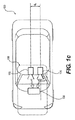
画像捕捉装置110及び120は、任意の適切な相対的高さにおいて車両150上に配置され得る。一例では、2つの画像捕捉装置110と120との間に高差がある場合があり、この高差はステレオ解析を可能にするのに十分なパララックス情報をもたらし得る。図1aに示すように、2つの画像捕捉装置110及び120を装着する高さの差をdhで示す。画像捕捉装置110と120との間には、例えば処理装置130によるステレオ解析用の追加のパララックス情報を与える、横方向の変位差もあり得る。図1bに示すように、横方向の変位差はdxで示され得る。一部の実施形態では、画像捕捉装置110と画像捕捉装置120との間に前方又は後方の変位(例えば距離変位)があり得る。例えば、画像捕捉装置110を、画像捕捉装置120の0.5から2メートル又はそれを上回る距離後ろに配置することができる。この種の変位は、画像捕捉装置の1つが、他の画像捕捉装置の潜在的な死角を有効範囲として含むことを可能にし得る。図1(a)に示すように、距離変位の差をdzで示す。図1cに示すように、他の実施形態では、距離変位dz=0及び高さ変位dh=0だが、横方向の変位dxがある場合がある。
画像捕捉装置110は、任意の適切な分解能(例えば画像センサに関連する画素数)を有することができ、画像捕捉装置110に関連する画像センサの分解能は、画像捕捉装置120に関連する画像センサの分解能よりも高くても、低くても、同じでも良い。一部の実施形態では、画像捕捉装置110及び/又は画像捕捉装置120に関連する画像センサが、640x480、1024x768、1280x960、又は他の任意の適切な分解能を有し得る。
The
フレームレート(例えば画像捕捉装置が、次の画像フレームに関連する画素データの捕捉に進む前に或る画像フレームの1組の画素データを取得する速度)は制御可能とすることができる。画像捕捉装置110に関連するフレームレートは、画像捕捉装置120に関連するフレームレートよりも高くても、低くても、又はそれと同じでも良い。画像捕捉装置110及び120に関連するフレームレートは、フレームレートのタイミングに影響し得る様々な要因に依拠する場合がある。例えば、画像捕捉装置110及び/又は120の一方若しくは両方が、画像捕捉装置110及び/又は120内の画像センサの1つ又は複数の画素に関連する画像データの取得前に又は取得後に課せられる、選択可能な画素遅延期間を含む場合がある。概して、各画素に対応する画像データは、装置のクロックレートに従って取得され得る(例えば1クロックサイクル当たり1画素)。更に、ローリングシャッターを含む実施形態では、画像捕捉装置110及び/又は120の一方若しくは両方が、画像捕捉装置110及び/又は120内の画像センサの画素行に関連する画像データの取得前に又は取得後に課せられる、選択可能な水平帰線期間を含む場合がある。更に、画像捕捉装置110及び/又は120の一方若しくは両方が、画像捕捉装置110及び/又は120の画像フレームに関連する画像データの取得前に又は取得後に課せられる、選択可能な垂直帰線期間を含む場合がある。
The frame rate (eg, the rate at which the image capture device acquires a set of pixel data for an image frame before proceeding to capture pixel data associated with the next image frame) can be controllable. The frame rate associated with the
これらのタイミング制御は、例えそれぞれの線走査速度が異なっても、画像捕捉装置110及び120に関連するフレームレートを同期できるようにし得る。以下でより詳細に論じるように、幾つかある要因(例えば画像センサの分解能、最大線走査速度等)の中で特に、これらの選択可能なタイミング制御は、画像捕捉装置110の視野が画像捕捉装置120の視野と異なっても、画像捕捉装置110の視野が画像捕捉装置120の視野と重複する領域からの画像捕捉を同期できるようにし得る。
These timing controls may allow the frame rates associated with the
更に、画像捕捉装置110及び/又は120内のフレームレートのタイミングは、関連する画像センサの分解能に依拠し得る。例えば、両方の装置について同様の線走査速度を仮定し、一方の装置が640x480の分解能を有する画像センサを含み、もう一方の装置が1280x960の分解能を有する画像センサを含む場合、高い解像度を有するセンサから画像データのフレームを取得するのにより長い時間が必要である。
Further, the frame rate timing within the
画像捕捉装置110及び/又は120内の画像データ取得のタイミングに影響する可能性がある別の要因は、最大線走査速度である。例えば、画像捕捉装置110及び/又は120内に含まれる画像センサから画像データの行を取得するには、幾ばくかの最低限の時間がかかる。画素遅延期間が追加されないと仮定し、画像データの行を取得するためのこの最低限の時間は、特定の装置の最大線走査速度に関係する。高い最大線走査速度を提供する装置は、低い最大線走査速度を有する装置よりも高いフレームレートを提供する潜在能力がある。一部の実施形態では、画像捕捉装置120が、画像捕捉装置110に関連する最大線走査速度よりも高い最大線走査速度を有し得る。一部の実施形態では、画像捕捉装置120の最大線走査速度が、画像捕捉装置110の最大線走査速度の1.25倍、1.5倍、1.75倍、2倍、又はそれを上回り得る。
Another factor that can affect the timing of image data acquisition within the
別の実施形態では、画像捕捉装置110及び120が同じ最大線走査速度を有し得るが、画像捕捉装置110がその最大走査速度以下の走査速度で動作させられる。画像捕捉装置120が、画像捕捉装置110の線走査速度に等しい線走査速度で動作するようにシステムが構成され得る。他の例では、画像捕捉装置120の線走査速度が、画像捕捉装置110の線走査速度の1.25倍、1.5倍、1.75倍、2倍、又はそれを上回り得るようにシステムが構成されても良い。
In another embodiment, the
一部の実施形態では、画像捕捉装置110及び120が非対称であり得る。つまり、画像捕捉装置110及び120は、異なる視野(FOV)及び焦点距離を有するカメラを含む場合がある。画像捕捉装置110及び120の視野は、例えば車両150の環境に対する所望の任意の領域を含み得る。一部の実施形態では、画像捕捉装置110及び120の何れか又は両方が、車両150の前方の環境、車両150の後方の環境、車両150の側面の環境、又はそれらの組合せの環境の画像データを取得するように構成され得る。
In some embodiments, the
更に、各画像捕捉装置110及び/又は120に関連する焦点距離は、各装置が車両150に対して所望の距離範囲にある物体の画像を取得するように、(例えば適切なレンズを含めること等によって)選択可能とすることができる。例えば一部の実施形態では、画像捕捉装置110及び120が、車両から数メートルの範囲内にある近距離からの物体の画像を取得し得る。画像捕捉装置110及び120は、車両から更に離れた距離(例えば25m、50m、100m、150m、又はそれを上回る距離)にある物体の画像を取得するように構成されても良い。更に、一方の画像捕捉装置(例えば画像捕捉装置110)が車両に比較的近い(例えば10m又は20mの範囲内の)物体の画像を取得できる一方、他方の画像捕捉装置(例えば画像捕捉装置120)が車両150からより離れている(例えば20m、50m、100m、150m等を上回る)物体の画像を取得できるように、画像捕捉装置110及び120の焦点距離が選択されても良い。
Further, the focal length associated with each
画像捕捉装置110及び120のそれぞれに関連する視野は、それぞれの焦点距離によって決まり得る。例えば焦点距離が増加するにつれて、対応する視野が低下する。
The field of view associated with each of the
画像捕捉装置110及び画像捕捉装置120は、任意の適切な視野を有するように構成することができる。或る特定の例では、画像捕捉装置110が46度の水平FOVを有することができ、画像捕捉装置120が23度の水平FOVを有することができる。別の例では、画像捕捉装置110が52度の水平FOVを有することができ、画像捕捉装置120が26度の水平FOVを有することができる。一部の実施形態では、画像捕捉装置120のFOVに対する画像捕捉装置110のFOVの比率が、1.5から2.0の間で変動し得る。他の実施形態では、この比率が1.25から2.25の間で変動し得る。
システム100は、画像捕捉装置110の視野が、画像捕捉装置120の視野と(少なくとも部分的に又は完全に)重複するように構成され得る。一部の実施形態では、システム100は、例えば画像捕捉装置120の視野が、画像捕捉装置110の視野に含まれ(例えば画像捕捉装置110の視野よりも狭く)、画像捕捉装置110の視野と共通の中心を共有するように構成され得る。他の実施形態では、画像捕捉装置110及び120が隣接FOVを捕捉することができ、又はそれらのFOV内に部分的重複を有しても良い。一部の実施形態では、より狭いFOVの装置120の中心を、より広いFOVの装置110の視野の下半分内(例えば図2aの線280よりも下の領域)に位置決めできるように、装置110及び120の視野を位置合わせすることができる。
The
図2aは、開示する一例示的実施形態による、異なる視野を有する2台のカメラの重複視野を示す。図2bは、開示する別の例示的実施形態による、異なる視野を有する2台のカメラの重複視野を表す。 FIG. 2a shows an overlapping field of view of two cameras having different fields of view, according to one disclosed exemplary embodiment. FIG. 2b represents the overlapping field of view of two cameras having different fields of view, according to another exemplary embodiment disclosed.
ワイドFOVカメラ110は、水平FOV210及び垂直FOV220によって画定され得る第1のFOV250を有する。一例では、ワイドFOVカメラ110が、46度の水平FOV210及び1280x960画素の画像分解能を有し得る。ワイドFOVカメラ110は、ローリング走査方向251を示すローリングシャッターを有することができる。ローリングシャッター方向251は、垂直又は水平な任意の方向であり得る。図2aの実施形態では、ローリングシャッターを使用することで、画像を複数の走査線、例えば走査線252及び253として捕捉できるようになる。
The
ナローFOVカメラ120は、水平FOV230及び垂直FOV240によって画定され得る第2のFOV260を有する。ナローFOVカメラ120も、ローリング走査方向261を示すローリングシャッターを有することができる。一例では、ナローFOVカメラ120が、23度の水平FOV230及びワイドFOVカメラ110と同じ又は異なる画像分解能を有し得る。例えば一部の実施形態では、ナローFOVカメラ120が1280x960の画像分解能を有し得る。他の実施形態では、ナローFOVカメラ120がワイドFOVカメラ110と異なる画像分解能を有し得る(例えば640x480画素)。ローリングシャッター方向261は、垂直又は水平な任意の方向とすることができ、ローリングシャッターは、例えば線262及び263を含む複数の走査線として画像を捕捉できるようにする。
The
狭いFOV260及び広いFOV250は、FOVに関して部分的に又は完全に重複するように設定することができる。図2a及び図2b内で網状線によって示す重複領域270は、狭い視野260が広い視野250と重複する領域を表す。図2aに示すように、領域270はナロー画像捕捉装置120の全視野に対応し得る。更に、画像捕捉装置110のより広い視野内の中心に領域270を置くように、画像捕捉装置110及び120の視野を位置合わせすることができる。或いは図2bに示すように、領域270は、より狭い視野の画像捕捉装置120の全視野を表す必要も、より広い視野の画像捕捉装置の視野内の中心に置く必要もない。むしろ、図2bに示すように、領域270は画像捕捉装置110の中心からずれても良い。更に、画像捕捉装置110及び画像捕捉装置120の全視野未満の重複領域に領域270が対応するように、画像捕捉装置110及び120の視野を位置合わせしても良い。
ローリングシャッターを使用する実施形態では、画像捕捉装置110からの画像フレームを、図2aの線252及び253等、一連の逐次的に取得される走査線として得ることができる。同様に、図2aに示すように、画像捕捉装置120に関連するローリングシャッターは、一連の逐次的に取得される走査線263及び263として画像フレームを捕捉できるようにする。画像捕捉装置110が画像捕捉装置120の焦点距離及び視野と異なる焦点距離及び視野を有し、両方の装置でローリングシャッターが使用される場合、画像捕捉装置110及び120は、重複領域270に対応するそのそれぞれの視野の部分を異なる時間に捕捉することができる。かかる同期の欠如は、取得画像の相関ステレオ解析上の問題を引き起こし得る。
In embodiments using a rolling shutter, the image frame from the
更に解説するために、或る例示的システムは、1280x960のセンサ分解能をそれぞれ有する画像捕捉装置110及び120を含み得る。従って、ローリングシャッターを使用して両方の画像装置から画像フレームを取得する場合、1280画素の画像データをそれぞれ含む一連の960本の走査線として両方の捕捉装置からの画像フレームが取得される。図2aに示すように、この例では画像捕捉装置110が52度の視野を有することができ、画像捕捉装置が26度の視野を有することができ、両方の視野が共通の中心を共有することができる。両方の画像捕捉装置が同様の線走査速度を含む場合、各画像捕捉装置の重複領域270に対応する画像フレームの部分の一部又は全てが異なる時間に取得されることが明らかになる。
For further discussion, an exemplary system may include
例えば、両方の画像捕捉装置がそれぞれの画像フレームを同時に取得し始める(即ち両方の画像捕捉装置の最初の走査線が同期される)と仮定した場合、画像捕捉装置120が重複領域270から最初の線を取得する間、画像捕捉装置は、例えば重複領域270の範囲外である自らの視野の上部から画像線を取得する。画像捕捉装置120が、画像捕捉装置110の視野の角度幅の半分である視野を有する例では、画像捕捉装置110は、走査線240に達する(自らの画像フレームの端から端までの4分の1)まで、重複領域270に対応する画像線を取得しない。ここでも両方の画像捕捉装置が同じ線走査速度を有すると仮定した場合、画像捕捉装置110が自らの走査線番号240に達するとき、画像捕捉装置120も、重複領域270の端から端までの25%である自らの走査線240を取得している。更に、画像捕捉装置120がその走査の最後の線(即ち走査線960)を終えるとき、画像捕捉装置120は重複領域270の下部にある。しかし、それと同時に、画像捕捉装置110は、重複領域270から外れた自らの視野の最後の線を取得している。実際に、画像捕捉装置110の走査線240から720しか重複領域270を含まないのに対し、画像捕捉装置120の全960本の走査線が重複領域270に対応する。更に、この例では、(図2aの破線280に対応する)中心走査線だけが両方の画像捕捉装置によって同時に捕捉される。重複領域270に対応する他の全ての線は異なる時間に取得され、そのことはやはり重複領域270に関連するステレオ解析を行う際の問題を引き起こし得る。
For example, assuming that both image capture devices begin to acquire their respective image frames simultaneously (i.e., the first scan line of both image capture devices is synchronized), the
但し、各画像捕捉装置の画像取得タイミング制御パラメータを調節することにより、重複領域270に対応する各画像捕捉装置の画像フレームの部分が同じ期間中に取得されることを確実にすることが可能であり得る。
However, by adjusting the image acquisition timing control parameter of each image capturing device, it is possible to ensure that the image frame portion of each image capturing device corresponding to the
概して、この同期は様々な方法で実現することができる。例えば一実施形態では、画像捕捉装置110に関連する線走査速度と異なる線走査速度を有するように、(より狭い視野を有する)画像捕捉装置120を構成することができる。例えば、画像捕捉装置120の線走査速度が、画像捕捉装置110の線走査速度よりも速くても良い。一部の実施形態では、画像捕捉装置120の線走査速度が、画像捕捉装置110の線走査速度よりも2倍(又はそれを上回って)速くても良い。概して、少なくとも重複領域270に対応する画像捕捉装置110及び120の両方の画像フレームの部分を同じ期間中に取得できるように、より狭い視野の画像捕捉装置120は十分速い走査速度を有するべきである。
In general, this synchronization can be achieved in various ways. For example, in one embodiment, the image capture device 120 (having a narrower field of view) can be configured to have a line scan speed that is different from the line scan speed associated with the
画像捕捉装置110が52度の視野を有し、画像捕捉装置110が26度の視野を有し、両方が1280x960の画像センサ分解能を含む例に戻り、重複領域270は、画像捕捉装置110の画像フレーム内の走査線240から720(合計480本の走査線)に対応する。他方で、重複領域270は、画像捕捉装置120の全960本の走査線に対応する。その結果、画像捕捉装置110の線240から720を画像捕捉装置120の960本の走査線と同じ期間中に捕捉するために、画像捕捉装置120の線走査速度は画像捕捉装置110の線走査速度よりも少なくとも2倍速くても良い。かかる構成は、重複領域270に対応する線240から720までの480本の走査線を画像捕捉装置110が取得するのにかかるのと同じ時間内に、画像捕捉装置120が全960本の線を捕捉することを可能にし得る。
Returning to the example where the
但し、線走査速度は、重複領域270に対応するそれぞれの画像フレームのそれらの部分の取得を同期できるようにする唯一のタイミング制御パラメータではない。重複領域270内の所望の捕捉同期を実現するために、画像捕捉装置110及び120の一方又は両方の水平帰線期間、垂直帰線期間、及び画素遅延を選んでも良い。例えば、重複領域270からの画像取得を同期することを確実にするのに、画像捕捉装置120の線走査速度が遅すぎる可能性がある実施形態では、画像捕捉装置110(より広い視野の装置)の水平帰線期間を長くして画像捕捉装置110の実効線走査速度を遅くしても良い。加えて、又は或いは、画像捕捉装置110に関連する画素遅延を高めて画像捕捉装置110の実効線走査速度を遅くしても良い。
However, the line scan speed is not the only timing control parameter that allows the acquisition of those portions of each image frame corresponding to the
重複領域270内の画像取得の同期を可能にするのに十分な線走査速度を画像捕捉装置120が有する場合でも、重複領域270内の画像取得の同期を繰り返すことができるように、各画像捕捉装置の総フレームレートが同じであり得る。この例に戻り、重複領域270内の画像取得を同期するために、画像捕捉装置120は、画像捕捉装置110が走査線240に到達するとき走査線番号1においてデータを取得し始めるものとする。画像捕捉装置110が線240から720まで取得する間、画像捕捉装置120は自らの走査線の全960本を取得する。画像捕捉装置110が線721から960まで、及び線1から239まで捕捉している間、各フレーム内で重複領域270が同期することを確実にするために、画像捕捉装置120はアイドル状態のままであるものとする。画像捕捉装置110が重複領域270外の画像データを取得できるようにするように、画像捕捉装置120のこの遅延をもたらすために、画像捕捉装置110よりも長い垂直帰線期間によって画像捕捉装置120を構成することができる。
Each image capture so that the image capture synchronization within the
上記に記載した一部の実施形態では、画像捕捉装置110及び120からの画像の同期部分が重複領域270に対応することに留意すべきである。他の事例では、画像捕捉装置110及び120の重複部分が、重複領域270内に同期された1本の線を有することができ、その線から離れると各線がより同期しなくなる場合がある。これをdTLによって示すことができる。システムは、例えば画像捕捉装置120の走査線速度を調節することにより、線が同期されなくなる率を減らすことができる。例えば、画像捕捉装置110と120との間の焦点距離比が2である場合、システムはTLn=0.5*TLwを調節することができ、その調節によりdTL=0になり得る。別の例では、TLn=0.6*TLwである。一部の実施形態では、重複領域270内の画像取得の「同期」を、両方の画像捕捉装置によるその領域内の画像取得のタイミングが同一でなくても実現することができる。例えば、重複領域270内の装置120からの画像部分の取得との間のタイミング差が、重複領域270に対応する画像部分を装置110が取得するのにかかる時間の1%、5%、10%、又は15%の範囲内にある場合、(例えばステレオ解析を可能にするのに)十分な同期を実現することができる。
It should be noted that in some embodiments described above, the synchronized portion of the image from the
例えば上記のように、画像捕捉装置120と110との間に焦点距離間の特定の比率(例えば2:1)がある場合、より広いFOVの装置110の線走査速度に対するより狭いFOVの装置120の線走査速度の比率は、全重複領域270にわたって取得画像を同期するために、少なくとも焦点距離比と同じ高さであるべきである。但し、一部の実施形態では、更に低い走査速度比が依然として有用な場合がある。例えば、画像捕捉装置120と110との間の焦点距離比よりも低い線走査速度比でも、重複領域270の一部(及びしばしば広い部分)にわたり、装置110及び120の画像部分を依然として同期することができる。
For example, as described above, if there is a certain ratio (eg, 2: 1) between the focal lengths between the
例えば装置120と110との間の2:1の焦点距離比を仮定し、少なくとも2:1の線走査比が、全FOV重複領域270にわたり画像を同期できるようにする。但し、全領域270未満にわたる画像の同期も依然として有用であり得る。例えば一部の実施形態では、1.9、1.8、1.7、1.6、1.5、又はそれ未満の線走査比が、重複領域270の領域の少なくとも一部内で装置110及び120からの画像間の有用な同期水準を依然として提供し得る。
For example, assuming a 2: 1 focal length ratio between
重複領域270内で装置110の画像部分の取得を装置120の画像部分の取得と同期できる期間は、装置110の線走査速度と装置120の線走査速度との間の比率に関係し得る。例えば、FOVの比率が2だが走査線タイミングの最大比が1.8である場合、この期間は1.8の走査線タイミング比(並びに適用される任意の画素遅延、水平帰線期間等)に基づき得る。
The period during which the acquisition of the image portion of the
タイミング制御パラメータ(例えば線走査速度、垂直帰線期間、水平帰線期間、画素遅延等)を調節することに加え、タイミング制御パラメータの調節と共に又はそれとは別に他の技法も使用することができる。一部の実施形態では、画像捕捉装置110よりも低い分解能の画像センサを用いて画像捕捉装置120(より狭い視野の装置)を構成することができる。従って、画像捕捉装置110が1280x960の分解能を有する画像センサを有する場合、更に低い分解能(例えば640x480)を有する画像センサを用いて画像捕捉装置120を構成することで、より速い画像捕捉装置120の線走査速度の必要性を軽減することができる。上記の同じ52度/26度の例を仮定し、両方の装置が同様の線走査速度を使用しても、重複領域270内で、画像捕捉装置110内の1280x960画素センサを画像捕捉装置120内の640x480画素センサと同期させることができる。この例では、画像捕捉装置110が重複領域270に対応する480本の線(即ち画像捕捉装置110の線240から720)を取得する間、画像捕捉装置120は、重複領域270に対応する自らの480本の走査線を取得する。
In addition to adjusting timing control parameters (eg, line scan speed, vertical blanking period, horizontal blanking period, pixel delay, etc.), other techniques can be used in conjunction with or separately from adjusting timing control parameters. In some embodiments, the image capture device 120 (a device with a narrower field of view) can be constructed using an image sensor with a lower resolution than the
加えて、又は或いは、より狭い視野の画像捕捉装置が各フレーム内の全ての画像線をサンプリングしない場合、より狭い視野の装置のより速い走査速度の需要が軽減され得る。例えば、或るフレームの取得中に、入手可能な走査線のサブセット(例えば奇数の走査線)だけをサンプリングするように画像捕捉装置120を構成することができる。次のフレームの捕捉中に、偶数の走査線をサンプリングするように画像捕捉装置120を構成することができる。この種のインタレース技法により、重複領域270に関連する画像データを取得するのにかかる時間を、フレームごとに全走査線を取得する技法に比べて半分に減らすことができる。
In addition, or alternatively, if the narrow field of view image capture device does not sample all image lines within each frame, the demand for faster scan speeds of the narrow field of view device may be reduced. For example, the
タイミング制御パラメータの選択に関連する別の例では、画像捕捉装置120の線走査速度を増加できる場合、焦点距離間の目標比率も、それらが線のタイミング間の比率に一致するように低下させることもできる。例えば、画像捕捉装置110が46°の水平FOV210を有し、45KHz(22.2μsec)の線のタイミングで実行されるが、センサは60KHz(15.2μsec)の線のタイミングをサポートできる場合、画像捕捉装置120の32°の水平FOV230をサポートし、同期することができる:
![]()
![]()
ここでは、TLnが15.2μsec、TLwが22.2μsec、広い水平FOV210が46°であり得る。
Here, TLn may be 15.2 μsec, TLw may be 22.2 μsec, and the wide
30°の水平FOV230を有する画像捕捉装置120は、分解能の(50%の)増加及び小さいδTL値をもたらすための適切な解を表し得る:
δTL=αTLn−TLw (4)
An
δT L = αT Ln −T Lw (4)
ここで、
![]()
![]()
![]()
![]()
画像捕捉装置110及び画像捕捉装置120に関連し、焦点距離/視野の任意の適切な比率を選択することができる。一部の実施形態では、この比率を1.5、1.6、1.7、1.8、2まで、又は2を上回って設定することができる。
In connection with
上記のように、同じ速度でフレームを出力するように画像捕捉装置110及び画像捕捉装置120の両方を構成することができる。例えば、フレーム当たりの総クロック数(取得される走査線、帰線期間、遅延等を含む)を両方の装置で同じとすることができる。重複領域270内の所望の同期を実現するために、線走査速度のタイミング掛ける重複領域270を覆う行数が、2つの画像捕捉装置について同じであり得る。
As described above, both the
カメラが同期されると、重複領域270内の所望の同期及び同様のフレームレートが保たれるように、それらのカメラはロックステップ動作を保つことができる。システムは、第1の画像捕捉装置110及び第2の画像捕捉装置120が、重複領域270内の画像データを捕捉する際に及び/又は全体的なフレームレートの点で同期したままであるかどうかを判定するためのタイミングチェックを周期的に行うことができる、1個又は複数個の処理装置(例えば処理装置130)を含み得る。同期の欠如が認められる場合、処理装置130は、1つ又は複数のタイミングパラメータを調節することができ、又は画像走査の1つ若しくは複数の側面をリセットすることができる(例えば最初の走査線等の所望の走査線番号や画像フレーム内の他の任意の走査線へのハードジャンプ)。かかる再同期プロセスは、画像捕捉装置110及び120の動作全体を通して周期的に行うことができる。
When the cameras are synchronized, they can maintain a lockstep operation so that the desired synchronization and similar frame rate within the
一部の実施形態では、画像捕捉装置110及び120を独立した用途で使用することができる。他の実施形態では、例えば重複領域270内の画像捕捉を同期することが、両方の装置からの情報を組み合わせてステレオ解析(例えば特にステレオ奥行決定)を行う応用を可能にし得る。
In some embodiments, the
上記のように画像捕捉装置110及び120内のローリングシャッターを使用することに加え、一部の実施形態ではグローバルシャッターを使用することがある。かかる実施形態では、画像フレームを一連の逐次的に取得される画像走査線として捕捉するのではなく、特定の画像内の全ての画素行が同時にサンプリングされ、取得される。
In addition to using the rolling shutter in the
図3は、グローバルシャッターを有する画像捕捉装置を用いるシステム内で使用するための例示的プロセスを表す。図3に示すように、画像捕捉装置110及び120がグローバルシャッターを有するシステムでは、重複領域270内のステレオ処理が、重複領域270の外側のワイドFOVカメラの画像データを単純にトリミングすることを含み得る(ステップ310)。次に、マッチする画像の対を得るために、より狭いFOVの画像捕捉装置の画像データを平滑化し、サブサンプリングすることができる(ステップ320)。次いで、マッチする画像の対に基づいてステレオ処理を完了することができる(ステップ331)。マッチする画像の対が得られない場合、修正ステップが実際に必要であり得る(ステップ332)。
FIG. 3 represents an exemplary process for use in a system using an image capture device with a global shutter. As shown in FIG. 3, in a system where the
上記のローリングシャッターの実施形態では、重複領域270内の画像データの捕捉を同期し、画像捕捉装置110と120との間の全体的なフレームレートも同期するために、タイミング制御パラメータ等を制御することができる。このハードウェアによるフロントエンドの同期解決策に加え、他の実施形態は、重複領域270の画像データをステレオ解析するための基礎としてバックエンド処理に依拠することができる。つまり、重複領域270内の画像データを画像捕捉装置110及び120に同じ期間にわたって取得させるのではなく、この画像データは異なる期間に捕捉することができ、そのデータに基づく有意味のステレオ解析を可能にするために捕捉画像データに対して処理を行うことができる。
In the rolling shutter embodiment described above, timing control parameters and the like are controlled to synchronize the capture of the image data in the
バックエンド処理の解決策は、画像捕捉装置110の1本の走査線を画像捕捉装置120の1本の走査線と同期できるということに依拠し得る。同期される各画像捕捉装置の特定の線は、異なる画像フレーム内で被選択同期線が変わっても良いように選択可能であり得る。
The back-end processing solution may rely on being able to synchronize one scan line of the
特定の画像フレーム内で、両方の画像捕捉装置110及び120から集められる画像データが、被選択同期走査線において互いに対応する。図2a及び図2bに示す画像捕捉装置のように、異なる視野を有する画像捕捉装置では、同期線から離れた走査線が同期しなくなる。更に、画像走査線の同期の欠落は、被選択同期線から離れて増加する。
Image data collected from both
走査線が同期を欠く場合、(例えば重複領域270内の)対応する走査線が異なる期間中に捕捉される結果として画像データ内の視差が存在し得る。例えば、或る物体が画像捕捉装置110及び120に関連するシーンを進む場合、同期線において、画像捕捉装置110及び120の両方からの捕捉画像データがその物体の同じ位置を示す(各画像捕捉装置内の同期走査線が同じ期間中に捕捉されるからである)。しかし、同期線から離れて取得される画像走査線は同期を欠く場合があり、従って移動物体の位置の視差を引き起こし得る。
If a scan line lacks synchronization, there may be parallax in the image data as a result of the corresponding scan line being captured during different time periods (eg, in the overlap region 270). For example, if an object travels through the scene associated with the
52度のFOVを有する画像捕捉装置110、及び26のFOVを有する画像捕捉装置120、その両方の装置が1280x960の分解能を有する画像センサを含む例に戻り、被選択同期線は任意の被選択線位置において生じ得る。一部の実施形態では、同期線が重複領域270内に生じ得る。例えば、同期走査線が重複領域270の中心に選択されても良い。従って、重複領域270の中心にある同期線において取得される画像データは時間に関して一致するのに対し、その同期線から離れた線において捕捉される画像データは時間の点で一致しない。タイミングが一致しない水準は、同期線から離れて増加する。両方の画像捕捉装置の中心走査線が同期されている例では、重複領域270の最初の走査線が画像捕捉装置110及び120によって異なる時間に捕捉される。例えば、画像捕捉装置120(より狭いFOVの装置)では、重複領域270内で取得される最初の走査線が、フレーム内で取得される最初の走査線に対応する。他方で、画像捕捉装置110が重複領域270内で取得する最初の走査線は走査線番号240において生じる。しかし、画像捕捉装置110が走査線240を取得するのと同じ時間に、画像捕捉装置120も自らの走査線240を取得している可能性がある。但し、画像捕捉装置120では、走査線240が重複領域270を既に25%通過している。従って、画像捕捉装置110では、重複領域270内で取得される最初の走査線が、画像捕捉装置120によって重複領域270内の最初の画像走査線が捕捉された後で取得されることが分かる。
Returning to the example where the
被選択同期線に近づくにつれて減少するこの時間差は、画像の視差を引き起こし得る。例えば単純な例では、同期線から離れた走査線では、移動物体が画像捕捉装置120にとって見えるのと異なる位置に画像捕捉装置110にとっては見える場合がある。見かけの位置の差の程度は、時間差が同期線から離れて増えるにつれて増加し得る。
This time difference, which decreases as it approaches the selected sync line, can cause image parallax. For example, in a simple example, a scan line away from the synchronization line may be visible to the
但し、線を走査するタイミングが両方の画像捕捉装置110及び画像捕捉装置120で知られているので、引き起こされる視差の程度は予測可能である。従って、処理装置130は、線を走査するタイミングの差によって引き起こされる予期される視差を考慮に入れることにより、両方の装置から取得される画像データを解析することができ、重複領域270からステレオ解析情報を得ることができても良い。
However, since the timing of scanning the line is known by both the
線を走査するタイミングは被選択同期線において収束するので、引き起こされる視差が小さく更には些細である、同期線に関する走査線の帯が存在し得る。従って、同期走査線の周りの走査線の帯では、認められる視差に対処するためにより少ない処理が必要であり得る。一部の実施形態では、関心のある物体に重複するように同期走査線を思慮深く選択することにより、この視差が少ない帯を関心のある物体の中心に置くことができる。 Since the timing of scanning the line converges on the selected sync line, there may be a scan line band with respect to the sync line, where the parallax caused is small and even trivial. Accordingly, less processing may be necessary in the band of scan lines around the synchronous scan line to deal with perceived parallax. In some embodiments, this low parallax band can be centered on the object of interest by judicious selection of the synchronous scan line to overlap the object of interest.
道路上で遭遇する様々な種類の物体(例えば垂直物体、移動物体、路面に近い低い物体等)は、取得される画像の視差に関して異なるように振る舞い得る。従って、同期走査線の選択は、シーン内(例えば重複領域270内)の関心のある物体の種類によって決まり得る。 Various types of objects encountered on the road (eg vertical objects, moving objects, low objects close to the road surface, etc.) may behave differently with respect to the parallax of the acquired image. Thus, the selection of synchronous scan lines may depend on the type of object of interest in the scene (eg, in the overlap region 270).
上記のように、同期線の位置は調節することができる。特定の線の同期は、任意の特定の行を選択することを、ことによると可能にする、基本的な同期技術を提供する任意の画像捕捉装置110、120上で実行することができる。しかし、1本の線しか同期できない場合、あらゆる状況用の1本の最適な線がない場合がある。つまり、2つ以上の画像フレーム間で同期されている線を切り替えることが有用であり得る。被選択同期走査線のかかる調節は、任意の適切な技法によって実現することができる。
As described above, the position of the synchronization line can be adjusted. The synchronization of a particular line can be performed on any
例えば、一部の実施形態では、ナローFOV画像捕捉装置120の垂直帰線期間がフレーム間で調節されても良い。一部の実施形態では、画像捕捉装置120による画像の取得が画像捕捉装置110に遅れ、その後追い付くように垂直帰線期間を選択することができ、そのため、異なる画像フレーム内で異なる線が同期される。別の実施形態では、ナローFOV画像捕捉装置120の垂直帰線を、画像捕捉装置110に対して所望の差に設定することができる。例えば、画像捕捉装置120の垂直帰線期間がワイドFOV画像捕捉装置110よりも100ライン少ない場合、その後の全てのフレーム内で同期線の位置が或る程度異なる(例えばy=−100)。
For example, in some embodiments, the vertical blanking period of the narrow FOV
一例では、同期線の選択が車速に依存するようにシステムを構成することができる。別の例では、選択された第1の走査線及び選択された第2の走査線の両方が、(例えば関心のある物体が位置し得る)車両から離れた所定の距離に対応するようにシステムを構成することができる。 In one example, the system can be configured such that the selection of the synchronization line depends on the vehicle speed. In another example, the system such that both the selected first scan line and the selected second scan line correspond to a predetermined distance away from the vehicle (eg, an object of interest may be located). Can be configured.
上記のように、画像捕捉装置110と120との間で1本の走査線だけが同期され且つ空間的に整列される場合、同期線からの距離が増すにつれ、その同期線よりも上の及び下の線が徐々に同期しなくなる可能性があり:
δt(y)=(y−yО)δTL (1)
但しy0は、正しく同期されている両方の画像内の1本の線とすることができ、δTLは次式で表わすことができ:
δTL=2TLn−TLw (2)
但しTLnはナローカメラ120の線のタイミングとすることができ、TLwはワイドカメラ110の線のタイミングとすることができる。多くの場合、TLn=TLwであり、δTLは1本の線のタイミング(例えば1/45,000sec)であり得る。
As described above, when only one scan line is synchronized and spatially aligned between the
δt (y) = (y- y О) δT L (1)
Where y 0 can be a single line in both images that are correctly synchronized and δTL can be expressed as:
δT L = 2T Ln −T Lw (2)
However, TLn can be the line timing of the
更に、上記のように1本の線しか同期できない場合、その線は特定の用途の要件に基づいて選ぶことができる。例えば、路面の用途ではy=−100前後の同期線が有利であり得る。水平線に近い行は、全般的な物体検出に有用であり得る。従って、2つ又は3つ(若しくはそれを上回る数)の設定間、例えば行y=0と行y=−100との間で同期される線を切り替えることが有用であり得る。 Furthermore, if only one line can be synchronized as described above, that line can be selected based on the requirements of a particular application. For example, a synchronization line around y = -100 may be advantageous for road applications. Rows close to the horizon can be useful for general object detection. Thus, it may be useful to switch the line that is synchronized between two or three (or more) settings, eg, between row y = 0 and row y = -100.
2台の撮像装置が第1の撮像装置の行に同期されると仮定する特定の例では、共通画像の中心線(y=0)を同期することができる。ナローFOV装置120の垂直帰線期間がワイドFOV装置110よりも100ライン長い場合、次のフレームでは、線y=−100が同期され得る。変更を加えない場合、次のフレームでは線y=−200が同期され、その後も同様に続き得る。これはやがて循環する場合があり、線y=0が慎重に再び同期し得る。例えば、1000本の線があり、垂直帰線が500本の線である場合、この循環は15フレーム後に起こり得る。
In a specific example that assumes that two imaging devices are synchronized to the first imaging device row, the centerline (y = 0) of the common image can be synchronized. If the vertical blanking period of the
別の例では、システムが、ナローFOV装置120の垂直帰線を、ワイドFOV装置110よりも100ライン少なく設定することができる(例えば400ライン対500ライン)。この設定は変えてはならないが、ナローFOVカメラ120の全ての第2のフレームが、ワイドFOVカメラ110に再同期される。ワイドFOVカメラ110は、自走(マスタとも呼ぶ)とすることができる。Aptina 1M Pixelセンサでは、トリガピンを使用して同期を行うことができる。トリガピンは、第2のフレームの読出し後(例えばy=−100が同期される場合)に「0」に設定することができる。ワイドFOVカメラ110からの読出開始のNライン前に、トリガピンを「1」に設定することができる。Nは、ナローFOVカメラ120内で設定される積分時間の長さによって決定され得る。Nが小さい場合、垂直帰線中にトリガピンを下げる及び上げる時間があり得る。夜の条件及び非常に長い積分時間では、ナローFOVカメラ120が、フレームを飛ばさなければならないことがある。
In another example, the system can set the vertical retrace of the
一実施形態では、第1の画像の第1の重複部分の少なくとも第1の領域を、第2の画像の第2の重複部分の対応する第2の領域に対して相関させることが、第2の画像の取得に関連する第2の走査線と同期すべき第1の画像の取得に関連する第1の走査線を選択すること、並びに第1の画像の第1の重複部分内の、及び第2の画像の第2の重複部分の対応する領域内の水平帯内で高密度奥行マップの計算を行うことを含むようにシステムを構成することができる。水平帯が少なくとも100画素の幅を表すようにシステムを構成しても良い。 In one embodiment, correlating at least a first region of the first overlapping portion of the first image with a corresponding second region of the second overlapping portion of the second image comprises: Selecting the first scan line associated with the acquisition of the first image to be synchronized with the second scan line associated with the acquisition of the first image, and in the first overlapping portion of the first image, and The system can be configured to include performing a dense depth map calculation within a horizontal band within a corresponding region of the second overlapping portion of the second image. The system may be configured such that the horizontal band represents a width of at least 100 pixels.
次いでシステムは、画像の様々な帯を設定ごとに処理することができる。フレームごとに全画像を処理することの計算コストが高すぎる可能性がある場合、最適化された帯を処理することが、実行可能な代替策であり得る。一例では、次いで画像の様々な帯を、画像捕捉装置110、120の設定ごとに処理することができる。
The system can then process various bands of the image for each setting. If the computational cost of processing the entire image per frame may be too high, processing an optimized band may be a viable alternative. In one example, various bands of the image can then be processed for each setting of the
第1の画像の第1の重複部分の少なくとも第1の領域を、第2の画像の第2の重複部分の対応する第2の領域に対して相関させることが、第1の画像の第1の重複部分と第2の画像の第2の重複部分との間の高密度オプティカルフローを計算すること、及び高密度オプティカルフローを使用して第1の画像又は第2の画像の少なくとも1つをワープさせることを含むようにシステムを構成することができる。システムは、相関関係を確立するために、第1の画像内の物体特徴を第2の画像内の物体特徴に対してマッチするために取得画像を処理することができる。システムは、画素ごとの奥行情報を含む視差マップを作成することができる。特に、視差マップの計算は、撮像装置110及び120の情報を組み合わせることを含み得る。視差は、第1の画像及び第2の画像内の対応する点のx座標間の距離を典型的には画素単位で表し得る。第1の画像及び/又は第2の画像内の画素ごとに、視差マップは画像点の視差及び奥行情報を含み得る。システムは、様々な分解能で視差画像を生成することができる。
Correlating at least a first region of the first overlap portion of the first image with a corresponding second region of the second overlap portion of the second image is the first of the first image. Calculating a high density optical flow between the second overlap portion of the second image and the second overlap portion of the second image, and using the high density optical flow to determine at least one of the first image or the second image. The system can be configured to include warping. The system can process the acquired image to match object features in the first image against object features in the second image to establish a correlation. The system can create a parallax map that includes depth information for each pixel. In particular, the calculation of the parallax map may include combining information of the
一例では、システムは画像捕捉装置110及び120の奥行マップを求めて、シーン内の物体に関連する奥行情報を得ることができる。或る分解能における視差画像を用いて生成される奥行マップは、別の分解能における視差画像から生成される奥行マップと異なり得る。奥行マップは、シーン内の点までの奥行きを各画素値が示す、二次元画素配列とすることができる。
In one example, the system can determine a depth map of the
第2の複数の画像の少なくとも1つのフレームとの同期を実現するために、第1の複数の画像の少なくとも1つのフレームをワープさせるようにシステムを構成することができる。所定の位置における対象平面のホモグラフィによって第2の画像を前処理するように、少なくとも1個の処理装置が更に構成されるようにシステムを構成することができる。 In order to achieve synchronization with at least one frame of the second plurality of images, the system can be configured to warp at least one frame of the first plurality of images. The system can be configured such that at least one processing device is further configured to pre-process the second image by homography of the target plane at a predetermined location.
第1の画像の第1の重複部分の少なくとも第1の領域を、第2の画像の第2の重複部分の対応する第2の領域に対して相関させることが、第1の画像又は第2の画像の少なくとも1つを速度依存関数に従ってプレワープすることを含むようにシステムを構成することができ、プレワープは車両の移動に関連するホモグラフィ行列を計算すること、及び第1の画像又は第2の画像の少なくとも1つの、線のスキューに関連するホモグラフィを計算することによって実現される。 Correlating at least a first region of the first overlap portion of the first image with a corresponding second region of the second overlap portion of the second image is the first image or second The system can be configured to include prewarping at least one of the images according to a speed dependent function, the prewarp calculating a homography matrix associated with the movement of the vehicle, and the first image or second This is accomplished by calculating a homography related to the line skew of at least one of the images.
別の実施形態では、解決策は、複数のカメラのうちの1台の連続フレーム間の高密度オプティカルフロー(u,v)を計算し、各線が他のカメラと正確に同期されている場合に予期されるものであるように、そのフローを使用してフレームの1つをワープすることであり得る:

このシステムの一実施形態は、例えば垂直物体までの奥行測定に関係する場合があり、同期する線を選ぶこと、及びその線の周囲±100画素等の水平帯内で高密度奥行マップの計算を行うことを含み得る。選択される線は車速に依存し得る。選択される線は、特定の対象の位置に依存しても良い。ナローFOV画像を対象平面のホモグラフィによって前処理し、水平線に沿って探索を行うことができる最小操作奥行(minimum operating depth)を大きくすることができる。より近い対象に対応する大きい視差をマッチするとき、隣接する線を探索してマッチを求めることができる。エピポーラ線の小さな相違を更に許容するために、消失点(FOE)を推定することができる。FOEが分かっている場合、時間のずれを考慮に入れて距離推定値について解くことが可能であり得る。車両が主に前方向に動く場合、FOEの小さな誤差が大幅な補正を可能にし得る。ほぼ全範囲において、誤差を1m未満に減らすことができる。車両の回転を画像から、又は慣性センサから測定することができ、正確にモデル化することができる。 One embodiment of this system may involve, for example, depth measurements down to a vertical object, selecting a line to synchronize and calculating a dense depth map within a horizontal band such as ± 100 pixels around that line. Can include doing. The selected line can depend on the vehicle speed. The selected line may depend on the position of a particular object. Narrow FOV images can be pre-processed by homography of the target plane to increase the minimum operating depth that can be searched along the horizon. When matching a large parallax corresponding to a closer object, an adjacent line can be searched for a match. In order to further tolerate small differences in epipolar lines, the vanishing point (FOE) can be estimated. If the FOE is known, it may be possible to solve for the distance estimate taking into account the time lag. If the vehicle moves mainly in the forward direction, a small error in FOE may allow for significant correction. In almost the entire range, the error can be reduced to less than 1 m. Vehicle rotation can be measured from images or from inertial sensors and can be accurately modeled.
一例では、システムが、B=0.06mのステレオ基線、f=1600画素のワイドカメラ110の焦点距離(例えば6mmのレンズ及び3.75μmの画素を有するカメラ)、及び3200画素のナローカメラ120の焦点距離(例えば12mmのレンズ及び同じ画素)を有し得る。或る構成では、ステレオ基線をB=dx、dh=dz=0とすることができる。ナローFOV画像は、フルフレームで捕捉し、実効焦点距離を同じ1600画素に減らすソフトウェアによってサブサンプリングすることができる。ワイドカメラ110の線のタイミングは、TLw=1/45msecとすることができ、この速度はセンサが提供可能な限り速いものとすることができ、フレーム内の最小限の時間のずれをもたらし得る。その場合、システムはTLn=TLwを行うことができる。
In one example, the system has a stereo baseline of B = 0.06 m, a focal length of a
Z1の距離にある静的対象では、予期される視差はエピポーラ線に沿う
d=f*B/Z1 (8)
であり得る。画像が修正されたと仮定し、これらの線は画像行とすることができ、マッチングは一次元探索であり得る。ホスト車両がVの速度で対象に向かって動いている場合、画像点は、
dZ(y)=δt(y)V=(y2−y1)δTLV (11)
For a static object at a distance of Z1, the expected parallax is along the epipolar line d = f * B / Z 1 (8)
It can be. Assuming the image has been modified, these lines can be image rows and the matching can be a one-dimensional search. If the host vehicle is moving towards the subject at a speed of V, the image point is
dZ (y) = δt (y) V = (y 2 −y 1 ) δT L V (11)
今度は、第2の画像内の対応する点(x2,y2)を次式のように与えることができる:
ここでは、yepが非ゼロである可能性があっても、yep=0と仮定することができる。等式15は、y1の関数としてy2について解くことができる:
距離に依存するyのシフトにより、相関関係を見つけることがグローバルシャッターの事例又は静的な事例よりも難しい可能性がある。相関関係が見つかると、xのシフトによって引き起こされる視差誤差が距離推定値の著しい誤差を引き起こす場合がある。これらの問題は、本システムの様々な実施形態の中で論じるように軽減することができる。 Due to the distance-dependent shift of y, finding the correlation can be more difficult than the global shutter case or the static case. If a correlation is found, the parallax error caused by the x shift may cause a significant error in the distance estimate. These problems can be mitigated as discussed in various embodiments of the system.
図4は、車両から様々な距離にある対象の同期線からの画像内の点の変位の一例である。一例では図4は、V=30m/sと仮定し、車両から様々な距離値にある対象のyの変位を示す。 FIG. 4 is an example of the displacement of a point in the image from the subject synchronization line at various distances from the vehicle. In one example, FIG. 4 shows the displacement of y for an object at various distance values from the vehicle, assuming V = 30 m / s.
例えば図4に示すように、FOEは、(0,0)の(xep,yep)にあり得る。車両Zから様々な距離、例えばZ=2.5m(410)、Z=5m(420)、Z=10m(430)、Z=20m(440)、及びZ=30m(450)にある対象について、−250画素から250画素の間のy1の値の結果が示されている。行ごとに、V及びZに依存することができ、
![]()
![]()
一例では、第1の画像内の対象のy座標を表すことができる値y1を所与とすることができる。第2の画像内の対応する対象のy座標をy2で表わすことができる。十分に同期され、修正されたシステムでは、y2がy1に等しい場合がある。第2の画像内の対応する対象が同じ行の上にあっても良い。しかし、画像捕捉装置の前進移動により、第1の画像及び第2の画像がFOEから放射状に外れてフローする場合がある。時間差により、第1の画像内の対象が、第2の画像内の対応する対象よりも多く移動している可能性がある。第1の画像及び第2の画像における外向きのフロー(outward flow)は異なる場合があり、y2がy1と異なる原因になり得る。 In one example, a value y1 that can represent the y-coordinate of an object in the first image can be given. The y coordinate of the corresponding object in the second image can be represented by y2. In a fully synchronized and modified system, y2 may be equal to y1. Corresponding objects in the second image may be on the same line. However, the forward movement of the image capture device may cause the first image and the second image to flow radially away from the FOE. Due to the time difference, the object in the first image may have moved more than the corresponding object in the second image. The outward flow in the first image and the second image may be different and may cause y2 to differ from y1.
10mを上回る距離にある対象では、同期線y0から±100画素の領域内のy2の変位は1画素未満とすることができ、エピポーラ線に沿った探索が機能し得る。その領域を超えると、変位が大きくなる可能性があり、探索が二次元になる場合があり、FOEに依存し得る。例えば、約5mの距離にある対象では、同期線y0から±100画素の領域内のy2の変位は1.5画素に近い可能性がある。別の例では、約2.5mの距離にある対象では、同期線y0から±100画素の領域内のy2の変位は2.5〜3画素に近い可能性がある。 For objects at distances greater than 10 m, the displacement of y2 in the region of ± 100 pixels from the synchronization line y0 can be less than 1 pixel and the search along the epipolar line can function. Beyond that region, the displacement can be large and the search can be two-dimensional and can depend on FOE. For example, in an object at a distance of about 5 m, the displacement of y2 in the region of ± 100 pixels from the synchronization line y0 may be close to 1.5 pixels. In another example, for an object at a distance of about 2.5 m, the displacement of y2 in the region of ± 100 pixels from the synchronization line y0 can be close to 2.5-3 pixels.
図5は、車両から所与の距離にある対象に関する奥行推定値の一例である。一例では、図5は、30m/sの車両前進移動に関する、10mにある対象の奥行推定値を示し得る。分かっている奥行きを使用し、画像のx位置を横方向距離に変換することができる。行、車速、及び対象距離に同様に依存する、視差の著しい誤差があり得る。 FIG. 5 is an example of a depth estimate for an object at a given distance from the vehicle. In one example, FIG. 5 may show a depth estimate for an object at 10 m for a vehicle forward movement of 30 m / s. Using the known depth, the x position of the image can be converted to a lateral distance. There can be significant errors in parallax, which also depend on line, vehicle speed, and target distance.
図5による別の例では、同期された行の前後−100から100の間の水平方向の行(20画素ごと)の結果が示されている。例えば、同期された行から−100画素(510)の水平方向の行、同期された行から100画素(592)の水平方向の行、同期された行から−80画素(520)の水平方向の行、同期された行から80画素(591)の水平方向の行、同期された行から−60画素(530)の水平方向の行、同期された行から60画素(590)の水平方向の行、同期された行から−40画素(540)の水平方向の行、同期された行から40画素(580)の水平方向の行、同期された行から−20画素(550)の水平方向の行、同期された行から20画素(570)の水平方向の行、及び0画素(560)の水平方向の行に関する結果が示されている。 In another example according to FIG. 5, the result of a horizontal row (every 20 pixels) between −100 and 100 before and after the synchronized row is shown. For example, a horizontal row of −100 pixels (510) from the synchronized row, a horizontal row of 100 pixels (592) from the synchronized row, and a horizontal row of −80 pixels (520) from the synchronized row Row, horizontal row of 80 pixels (591) from the synchronized row, horizontal row of −60 pixels (530) from the synchronized row, horizontal row of 60 pixels (590) from the synchronized row -40 pixels (540) horizontal row from synchronized row, 40 pixels (580) horizontal row from synchronized row, -20 pixels (550) horizontal row from synchronized row Results are shown for a horizontal row of 20 pixels (570) from the synchronized row and a horizontal row of 0 pixels (560).
図6は、対象平面のホモグラフィを用いて画像を前処理することを含むフィックス後の、様々な距離値に関するyの変位を示す。一例では図6は、10mにおける面について補正した後の、V=30m/sを仮定した様々な距離値に関するyの変位を示す。yのシフトは、ホモグラフィによって概算することができる。ナローFOV画像を10m等の何らかの中間距離についてホモグラフィによって前処理する場合、yの変位が±1画素未満である最低距離を5mまで減らし且つ/又は改善することができる。 FIG. 6 shows the displacement of y for various distance values after the fix including pre-processing the image with object plane homography. In one example, FIG. 6 shows the displacement of y for various distance values assuming V = 30 m / s after correction for a surface at 10 m. The shift of y can be estimated by homography. If a narrow FOV image is preprocessed by homography for some intermediate distance, such as 10 m, the minimum distance where the displacement of y is less than ± 1 pixel can be reduced and / or improved to 5 m.
例えば、10mを上回る距離にある対象では、同期線y0から±100画素の領域内のyの変位は−1画素未満であり得る。約5mの距離にある対象では、同期線y0から±100画素の領域内のyの変位は1画素未満であり得る。別の例では、約2.5mの距離にある対象では、同期線y0から±100画素の領域内のyの変位が2画素に近い場合がある。 For example, for an object at a distance greater than 10 m, the displacement of y in the region of ± 100 pixels from the synchronization line y0 may be less than −1 pixel. For objects at a distance of about 5 m, the displacement of y in the region of ± 100 pixels from the synchronization line y0 may be less than one pixel. In another example, for an object at a distance of about 2.5 m, the displacement of y in the region of ± 100 pixels from the synchronization line y0 may be close to 2 pixels.
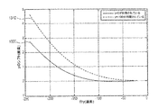
図7は、垂直物体の奥行測定を行うシステムで使用するための例示的プロセスを示す。別の実施形態では、同期するのに最適な線をシステムが選ぶことができる(ステップ710)。 FIG. 7 illustrates an exemplary process for use in a system that performs vertical object depth measurements. In another embodiment, the system can select the best line to synchronize (step 710).
10mにおける対象平面のホモグラフィにより、ナローFOV画像を前処理することができる(ステップ720)。このステップにより、水平線に沿って探索を行うことができる最小操作奥行を大きくすることができる。 A narrow FOV image can be pre-processed by homography of the object plane at 10 m (step 720). By this step, the minimum operation depth that can be searched along the horizontal line can be increased.
次いで、システムは、その同期線の周囲±100画素等の水平帯内で高密度奥行マップの計算を行うことができる(ステップ730)。例えば、30m先の道路上の線に対応する画像線を同期しても良い。
The system can then perform a high-density depth map calculation within a horizontal band such as ± 100 pixels around the synchronization line (step 730). For example, an image line corresponding to a line on a
最適な線は速度に依存する場合があり、システムは2秒先の道路上の線に対応する線を同期しても良い。最適な線は、特定の対象の位置にも依存し得る。
The optimal line may depend on speed, and the system may synchronize the line corresponding to the line on the
より近い対象に対応するより大きい視差をマッチするとき(ステップ740)、システムは隣接する線のマッチを探索することができる(ステップ741)。 When matching a larger parallax corresponding to a closer object (step 740), the system can search for a match of adjacent lines (step 741).
エピポーラ線の小さな相違を更に許容するために、FOEを推定することができる(ステップ750)。このプロセスは、エピポールを検出する際の小さな誤差に対して非常に敏感でなくても良い。 To further tolerate small differences in epipolar lines, FOE can be estimated (step 750). This process may not be very sensitive to small errors in detecting epipoles.
FOEが分かっている場合、時間のずれを考慮に入れ、等式13をZについて解くことが可能であり得る(ステップ751)。車両の動きが主に前方向であり得るので、FOEの小さな誤差、更にはxep=0と取ることが大幅な補正を可能にし得る。
If FOE is known, it may be possible to solve
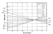
図8aは、車両の所与の前進移動及び横速度に関する、車両から所与の距離にある対象の奥行推定値を示す。例えば図8aは、30m/sの車両前進移動及びVx=2m/sの横速度に関する、10mにある対象の奥行推定値の一例を示し得る。 FIG. 8a shows the depth estimate of an object at a given distance from the vehicle for a given forward movement and lateral speed of the vehicle. For example, FIG. 8a may show an example of a depth estimate for an object at 10 m for a vehicle forward movement of 30 m / s and a lateral speed of Vx = 2 m / s.
図8aによる例では、同期された行の前後−100から100の間の水平方向の行(20画素ごと)の結果が示されている。例えば、同期された行から−100画素(810)の水平方向の行、同期された行から100画素(892)の水平方向の行、同期された行から−80画素(820)の水平方向の行、同期された行から80画素(891)の水平方向の行、同期された行から−60画素(830)の水平方向の行、同期された行から60画素(890)の水平方向の行、同期された行から−40画素(840)の水平方向の行、同期された行から40画素(880)の水平方向の行、同期された行から−20画素(850)の水平方向の行、同期された行から20画素(870)の水平方向の行、及び0画素(860)の水平方向の行に関する結果が示されている。 In the example according to FIG. 8a, the result of a horizontal row (every 20 pixels) between −100 and 100 before and after the synchronized row is shown. For example, a horizontal row of −100 pixels (810) from the synchronized row, a horizontal row of 100 pixels (892) from the synchronized row, and a horizontal row of −80 pixels (820) from the synchronized row Row, horizontal row of 80 pixels (891) from the synchronized row, horizontal row of −60 pixels (830) from the synchronized row, horizontal row of 60 pixels (890) from the synchronized row -40 pixels (840) horizontal row from synchronized row, 40 pixels (880) horizontal row from synchronized row, -20 pixels (850) horizontal row from synchronized row Results are shown for a horizontal row of 20 pixels (870) from the synchronized row and a horizontal row of 0 pixels (860).
図8bは、前進車両移動、及び横速度なしの補正された奥行推定値を示す。一例では、図8bは、前進移動だけを仮定して(例えばVx=0と仮定して)補正された奥行推定値を示し得る。ほぼ全範囲において、誤差を1m未満に減らすことができる。 FIG. 8b shows the corrected depth estimate without forward vehicle movement and lateral speed. In one example, FIG. 8b may show a corrected depth estimate assuming only forward movement (eg, assuming Vx = 0). In almost the entire range, the error can be reduced to less than 1 m.
図8bによる例では、同期された行の前後−100から100の間の水平方向の行(20画素ごと)の結果が示されている。例えば、同期された行から−100画素(811)の水平方向の行、同期された行から100画素(896)の水平方向の行、同期された行から−80画素(821)の水平方向の行、同期された行から80画素(895)の水平方向の行、同期された行から−60画素(831)の水平方向の行、同期された行から60画素(894)の水平方向の行、同期された行から−40画素(841)の水平方向の行、同期された行から40画素(881)の水平方向の行、同期された行から−20画素(851)の水平方向の行、同期された行から20画素(871)の水平方向の行、及び0画素(861)の水平方向の行に関する結果が示されている。 In the example according to FIG. 8b, the result of a horizontal row (every 20 pixels) between −100 and 100 before and after the synchronized row is shown. For example, a horizontal row of −100 pixels (811) from the synchronized row, a horizontal row of 100 pixels (896) from the synchronized row, and a horizontal row of −80 pixels (821) from the synchronized row Row, horizontal row of 80 pixels (895) from the synchronized row, horizontal row of −60 pixels (831) from the synchronized row, horizontal row of 60 pixels (894) from the synchronized row A horizontal row of −40 pixels (841) from the synchronized row, a horizontal row of 40 pixels (881) from the synchronized row, and a horizontal row of −20 pixels (851) from the synchronized row The results for a horizontal row of 20 pixels (871) and a horizontal row of 0 pixels (861) from the synchronized row are shown.
別の態様では、車両の回転を画像から、又は慣性センサから測定することができ、正確にモデル化することができる。次いで、例えばナローFOV画像を補正することができる。ヨーが水平スキューを引き起こす場合がある。ピッチが、同期線の周りで垂直圧迫又は垂直方向の伸びを引き起こす場合がある。 In another aspect, vehicle rotation can be measured from an image or from an inertial sensor and can be accurately modeled. Then, for example, a narrow FOV image can be corrected. Yaw can cause horizontal skew. The pitch may cause vertical compression or vertical stretch around the sync line.
このシステムの別の実施形態は、道路地物までの距離を推定することに関係することができ、速度依存関数に従ってナローFOV画像をプレワープすることを含み得る。より全般的な手法は、(1)路面上の車両の移動によるホモグラフィ行列を線のタイミングごとに計算すること、(2)その線のスキューのホモグラフィを線ごとに計算すること、及び(3)線のホモグラフィに従ってその線をワープすることを含み得る。各線のホモグラフィは、(1)或るフレームと次のフレームとの間の時間差のホモグラフィ行列を計算すること、(2)ホモグラフィによる画像の動きを計算すること、及び(3)時間スキューに応じて線ごとにその動きの一部を用いてワープすることによって概算することができる。ホモグラフィ行列は、連続した2つのナローFOV画像からも直接推定することができる。補正が必要な場合があり、他の実施形態で説明したように行うことができる。同期される画像行を最適化することにより、路面推定について改善された成果を得ることができる。 Another embodiment of the system can relate to estimating the distance to road features and can include prewarping the narrow FOV image according to a speed dependent function. A more general approach is to (1) calculate a homography matrix for vehicle movement on the road surface for each line timing, (2) calculate the line skew homography for each line, and ( 3) may include warping the line according to line homography. The homography of each line consists of (1) calculating the homography matrix of the time difference between one frame and the next frame, (2) calculating the motion of the image by homography, and (3) time skew. Can be approximated by warping with a portion of the movement for each line. The homography matrix can also be estimated directly from two consecutive narrow FOV images. Correction may be necessary and can be done as described in other embodiments. By optimizing the synchronized image rows, improved results for road surface estimation can be obtained.
一例では、2台のカメラを路面から1.25mのバックミラー付近に装着することができる。車速を30m/sとすることができる。車の前進移動により、画像内の道路上の点が下向き及び外向きのフローに遭遇する場合がある。フローの程度は時間差と共に増加し、その点における路面までの距離に反比例して増加し得る。後者の距離は、画像行に反比例し得る:
図9は、時間遅延がない場合及び時間遅延がある場合の、カメラの基線により路面上で予期される視差を示す。具体的には図9は、路面のステレオ視差のシミュレーションを示し、つまり、静的シーン並びに時間遅延及び前進移動による現在位置を仮定し、広角カメラによる原点、ナローカメラによるマッチする座標を示す。時間遅延は、同期線y=0から直線的に増加し得る。 FIG. 9 shows the parallax expected on the road surface by the camera baseline when there is no time delay and when there is a time delay. Specifically, FIG. 9 shows a simulation of stereo parallax on the road surface, that is, assuming a static scene and a current position due to time delay and forward movement, and showing the origin by a wide-angle camera and matching coordinates by a narrow camera. The time delay can increase linearly from the synchronization line y = 0.
図10は、画像行に応じた、時間遅延及び前進移動によるy方向のシフト(曲線1010)を示す。曲線1010は三次関数とすることができる。19m先とすることができる行y=−100までは、yのシフトが非常に小さい(0.5画素未満の)可能性がある。行y=−100未満では、システムが探索空間内で何らかの調節を行う必要があり得る。
FIG. 10 shows the y-direction shift (curve 1010) with time delay and forward movement as a function of the image row.
例えば、行0から行−124の間では、システムは(x1,y1)に中心を置く対象を行(y2=y1)に沿って探すことができ、行−125から行−170の間では、システムは1行下(例えばy2=y1−1)を探すことができ、行−170から行−190の間では、システムは2行下(例えばy2=y1−2)を探すことができ、行−190から行−220の間では、システムは3行下を探すことができ、その後も同様に続く。
For example, between
別の例では、探索行を切り替えるのではなく、システムが図10の関数に従って第2の画像をワープしても良い。このワーピングは、第2の画像を圧縮すること及び/又は修正すること(例えばグローバルシャッターの場合と同様の修正)を含み得る。ワーピング関数の数及びワーピングを伴う場合がある画像ぶれを減らすために、2つのワープを単一のマッピングに組み合わせることができる。第2の画像のワーピングは、比較的円滑な移行を与え得る。 In another example, rather than switching search rows, the system may warp the second image according to the function of FIG. This warping may include compressing and / or modifying the second image (eg, modification similar to that for a global shutter). In order to reduce the number of warping functions and image blur that may involve warping, the two warps can be combined into a single mapping. The warping of the second image can provide a relatively smooth transition.
図11は、道路地物までの距離を推定するためにシステムで使用するための例示的プロセスを示す。例えば、或る解決策では、プロセッサ130が、速度依存yシフト関数に従ってナロー画像を垂直にプレワープすることができる(ステップ410)。10m等の特定の距離を仮定し、プレワープすることには利点があり得る。
FIG. 11 illustrates an exemplary process for use in the system to estimate distance to road features. For example, in one solution, the
より概括的な手法は、路面上の車両の移動によるホモグラフィ行列HΠを線のタイミングTLごとにプロセッサ130が計算すること(ステップ420)とすることができ:
HΠ(y)=HΠ(TL)y (19)
A more general approach may be that the
H Π (y) = H Π ( TL ) y (19)
次いでこの手法は、プロセッサ130が、その線のホモグラフィに従ってその線をワープすることを含み得る(ステップ441)。プロセッサ130は、或るフレームと次のフレームとの間の時間差のホモグラフィ行列を計算し(ステップ442)、ホモグラフィによる画像の動きを計算し(ステップ450)、時間スキューに応じてその動きの一部を用いて線ごとにワープすること(ステップ460)によって線のホモグラフィを概算することができる。プロセッサ130は、連続した2つのナローFOV画像からホモグラフィ行列を直接推定することもできる。
The technique may then include the
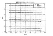
図12aは、車両の前進移動及び時間遅延によって引き起こされる画像内の様々な行の視差誤差を示す。具体的には、この図面は−20(ほぼゼロ)から始まり−240(画像のエッジにおける6画素を上回る誤差)まで20画素ごとに、画像行の時間遅延による視差誤差を示す。例えば、水平方向の行−20画素(1210)、水平方向の行−40画素(1220)、水平方向の行−60画素(1230)、水平方向の行−80画素(1240)、水平方向の行−100画素(1250)、水平方向の行−120画素(1260)、水平方向の行−140画素(1270)、水平方向の行−160画素(1280)、水平方向の行−180画素(1290)、水平方向の行−200画素(1291)、水平方向の行−220画素(1292)、及び水平方向の行−240画素(1293)の結果が示されている。 FIG. 12a shows the disparity errors of various rows in the image caused by forward movement of the vehicle and time delay. Specifically, the figure shows the parallax error due to the time delay of the image row for every 20 pixels starting from −20 (approximately zero) to −240 (an error exceeding 6 pixels at the edge of the image). For example, horizontal row—20 pixels (1210), horizontal row—40 pixels (1220), horizontal row—60 pixels (1230), horizontal row—80 pixels (1240), horizontal row -100 pixels (1250), horizontal rows-120 pixels (1260), horizontal rows-140 pixels (1270), horizontal rows-160 pixels (1280), horizontal rows-180 pixels (1290) The results are shown for horizontal row-200 pixels (1291), horizontal row-220 pixels (1292), and horizontal row-240 pixels (1293).
図12bは、その行上の視差の一部としての視差誤差(つまり真の視差)を示す。改善された結果を得るために、補正が必要な場合があり、他の実施形態で説明したように視差に対して行うことができる。同期され得る画像行を最適化することにより、路面推定について改善された成果を得ることができる。例えば、水平方向の行−20画素(1211)、水平方向の行−40画素(1221)、水平方向の行−60画素(1231)、水平方向の行−80画素(1241)、水平方向の行−100画素(1251)、水平方向の行−120画素(1261)、水平方向の行−140画素(1271)、水平方向の行−160画素(1281)、水平方向の行−180画素(1295)、水平方向の行−200画素(1296)、水平方向の行−220画素(1297)、及び水平方向の行−240画素(1298)の結果が示されている。 FIG. 12b shows the parallax error (ie true parallax) as part of the parallax on that row. Corrections may be necessary to obtain improved results, and can be done on parallax as described in other embodiments. By optimizing the image rows that can be synchronized, improved results for road surface estimation can be obtained. For example, horizontal row—20 pixels (1211), horizontal row—40 pixels (1221), horizontal row—60 pixels (1231), horizontal row—80 pixels (1241), horizontal row -100 pixels (1251), horizontal rows -120 pixels (1261), horizontal rows -140 pixels (1271), horizontal rows -160 pixels (1281), horizontal rows -180 pixels (1295) The results are shown for horizontal row-200 pixels (1296), horizontal row-220 pixels (1297), and horizontal row-240 pixels (1298).
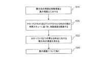
図13は、所与の行が同期されている場合の、時間遅延及び前進移動による予期されるyのシフトの一例である。一例では、図13は、行−100が同期される場合の時間遅延及び前進移動による予期されるyのシフト(曲線1320)、及び行0が同期される場合の時間遅延及び前進移動による予期されるシフト(曲線1210)を示す。行−100は、車の約20m先の行上の線に対応し得る。かかる行を選ぶことには利点があり得る。第1に、yのシフトが0.5画素未満である領域を−150まで増やすことができる。第2に、行−100が今や完全に同期できることを所与とし、この行についての距離測定値が正確である可能性があり、そのように正確であることは、路面に対する車両のピッチの優れた推定値をもたらし得る。このことは、垂直方向のプレワープを改善するために、更にはxの視差補正を改善するためにも使用することができる。
FIG. 13 is an example of the expected y shift due to time delay and forward movement when a given row is synchronized. In one example, FIG. 13 illustrates a time delay and expected y shift due to forward movement (curve 1320) when row-100 is synchronized, and an expected time delay and forward movement when
一例では、画像のワープが、等式Z=f*H/(y−y0)に基づき得る。水平線(y0)が線y=0にあると仮定した場合、Z=f*H/yが成立する。y0が分かっている場合、システムはy’=y−y0について解き、次いでZ=f*H/y’について解くことができる。他の例では、y0が分かっていない場合があり、例えば車両のピッチの移動によってフレーム間で変動し得る。そのような場合、視差を使用し、行−100における距離Z100を用いてy0を推定することができる:(y100−y0)=f*H/Z100、即ちy0=y100−f*H/Z100。調節されたy0は、より優れた補正ワープ、従ってより優れたx視差の補正を与えることができる。 In one example, the warp of the image may be based on the equation Z = f * H / (y−y0). Assuming that the horizontal line (y0) is on the line y = 0, Z = f * H / y holds. If y0 is known, the system can solve for y ′ = y−y0 and then Z = f * H / y ′. In other examples, y0 may not be known and may vary from frame to frame due to, for example, movement of the vehicle pitch. In such a case, parallax can be used to estimate y0 using the distance Z100 in row-100: (y100-y0) = f * H / Z100, ie y0 = y100-f * H / Z100. Adjusted y0 can give a better correction warp and thus better x parallax correction.
別の実施形態は、横方向に移動する物体又は任意のソースからの移動視差に関することができ、複数のフレームを使用することにより誤差を減らすことを含み得る。概して横方向の視差は、静的シーン上で測定される真の視差と、移動による視差とに分けることができる。移動視差は、ナローFOVカメラ及びワイドFOVカメラ内の行間の時間スキューに対して、ほぼ直線性を有することができる。分かっている2つの異なる時点における横方向の視差は、2つの未知数(移動視差及び真の視差)の2つの線形方程式を与えることができ、真の視差をもたらすために解くことができる。2つのサンプルは、例えば2つの異なるフレーム内の、ワイドFOV画像内で見られる物体上の特徴と、ナローFOVカメラ内で見られる同じ物体上の特徴との間で得ることができる。2つのサンプルは、異なる行上の物体上の2つの点からも得ることができ、それらの行ではそれらの点について同じ奥行きが予期される。この方法の改変形態は、同じカメラからの2つの画像間の或る特徴のオプティカルフロー又は高密度フローを計算することを含み得る。 Another embodiment may relate to moving parallax from a laterally moving object or any source and may include reducing errors by using multiple frames. In general, lateral parallax can be divided into true parallax measured on a static scene and parallax due to movement. The moving parallax can be substantially linear with respect to the time skew between the rows in the narrow FOV camera and the wide FOV camera. The known lateral parallax at two different time points can give two linear equations of two unknowns (moving parallax and true parallax) and can be solved to yield true parallax. Two samples can be obtained between features on the object seen in a wide FOV image, for example in two different frames, and features on the same object seen in a narrow FOV camera. Two samples can also be obtained from two points on an object on different rows, where the same depth is expected for those points. Variations on this method may include calculating the optical flow or high-density flow of a feature between two images from the same camera.
一例では、速度Vxで横方向に移動している物体が、基線による静的視差dBに誤差dvxを生じさせる場合がある。合計視差値は、次式に等しいものとすることができる:
誤差は、行に沿って一定であり、同期された行からの行の距離に関して直線的であり得る。 The error is constant along the row and can be linear with respect to the distance of the row from the synchronized row.
ゆっくりと動く対象の妥当性検証では、視差誤差が大きくない場合がある。図14aは、行(y)の関数としての、基線による真の視差に対する移動による視差誤差の比率の一例である。一例では、図14aは、物体が2m/sで横方向に移動しており(低速走行)、0.06mの基線の場合の、行(y)の関数としての(基線による真の視差に対する移動による視差誤差の)比率を示す(曲線1410)。誤差率は、奥行きに関して予期される誤差とすることができ、画像の上部及び下部では約15%の最大値に到達し得る。この用途では、この比率は許容可能と見なすことができる。何れにせよ、歩行者は、誤差がかなり少ない可能性がある中央領域内に概していることができる。 In the validation of a slowly moving object, the parallax error may not be large. FIG. 14a is an example of the ratio of the parallax error due to movement relative to the true parallax due to the baseline as a function of row (y). In one example, FIG. 14a shows (moving relative to true parallax by baseline as a function of row (y) when the object is moving laterally at 2 m / s (low speed travel) and a baseline of 0.06 m. Indicates the ratio (curve 1410). The error rate can be the expected error in depth and can reach a maximum of about 15% at the top and bottom of the image. For this application, this ratio can be considered acceptable. In any case, pedestrians can generally be in a central area that can be much less error-prone.
速く動く対象の妥当性検証では、複数のフレームを使用して正確な結果を与える方法について説明する。図14bは、物体が横方向に移動している場合の、基線による真の視差に対する移動による視差誤差の比率の一例である。一例では、図14bは、物体が15m/sで横方向に移動している場合(例えば50kmhで横切る車)の、基線による真の視差に対する移動による視差誤差の比率を示す(曲線1420)。この比率は、ナロー帯を除く全ての帯で20%を上回り得る。複数のフレームを使用することにより、誤差を大幅に減らすことができる。 In validating fast moving objects, we describe how to use multiple frames to give accurate results. FIG. 14b is an example of the ratio of the parallax error due to movement relative to the true parallax due to the baseline when the object is moving in the horizontal direction. In one example, FIG. 14b shows the ratio of the parallax error due to movement to the true parallax due to the baseline (curve 1420) when the object is moving laterally at 15 m / s (eg, a car crossing at 50 kmh). This ratio can exceed 20% in all bands except the narrow band. By using multiple frames, the error can be greatly reduced.
図15は、移動視差がある場合にシステムで使用するための例示的プロセスを示す。概して横方向の視差は、ホスト車両又は物体の静的シーン上で測定される真の視差と、移動による視差とに分けることができる(ステップ510)。移動による視差は、ナローFOVカメラ120及びワイドFOVカメラ110内の行間の時間スキューに対して、ほぼ直線性を有することができる(ステップ520)。(分かっている)2つの異なる時点における横方向の視差は、2つの未知数、真の視差及び移動視差の2つの線形方程式を与えることができ(ステップ530)、真の視差をもたらすために解くことができる(ステップ540)。2つのサンプルは、例えば2つの異なるフレーム内の、ワイドFOV画像内で見られる物体上の特徴と、ナローFOVカメラ内で見られる同じ物体上の特徴との間で得ることができる。2つのサンプルは、異なる行上の物体上の2つの点からも得ることができ、それらの行では、垂直支柱のエッジ等、それらの点について同じ奥行きが予期される。この方法の改変形態は、同じカメラからの2つの画像間の或る特徴のオプティカルフロー(u)又は高密度フローを計算することであり得る。次いで、
更に、本明細書では例示的実施形態を説明してきたが、均等の要素、修正、省略、(例えば様々な実施形態にわたる側面の)組合せ、適合、及び/又は改変を有する任意の及び全ての実施形態の範囲が本開示に基づいて当業者によって理解される。特許請求の範囲における限定は、特許請求の範囲の中で使用する言語に基づいて広義に解釈すべきであり、本明細書内で又は本願の出願手続き中に説明される例に限定されない。例は非排他的と解釈すべきである。更に、開示したルーチンのステップは、ステップを並べ替えること及び/又はステップを挿入し若しくは削除することを含む任意の方法で修正することができる。従って、本明細書及び例は専ら例示的と見なされることを意図し、真の範囲及び趣旨は添付の特許請求の範囲及びその均等物の全範囲によって示す。 Furthermore, although exemplary embodiments have been described herein, any and all implementations having equivalent elements, modifications, omissions, combinations (eg, aspects of the various embodiments), adaptations, and / or modifications The scope of the form will be understood by those skilled in the art based on the present disclosure. The limitations in the claims should be interpreted broadly based on the language used in the claims, and are not limited to the examples described herein or during the filing process of the present application. Examples should be interpreted as non-exclusive. Further, the disclosed routine steps may be modified in any manner including reordering steps and / or inserting or deleting steps. Accordingly, the specification and examples are intended to be regarded solely as exemplary, with the true scope and spirit being indicated by the appended claims and their full scope of equivalents.
Claims (19)
第1の視野を有し、前記車両に関連するシーンに関する第1の画像を取得するように構成される第1の画像捕捉装置であって、前記第1の画像は、ローリングシャッターを使用して捕捉される第1の一連の画像走査線として取得される、第1の画像捕捉装置と、
前記第1の視野とは異なり、前記第1の視野と少なくとも部分的に重複する第2の視野を有する第2の画像捕捉装置であって、前記第2の画像捕捉装置は、前記車両に関連する前記シーンに関する第2の画像を取得するように構成され、前記第2の画像は、ローリングシャッターを使用して捕捉される第2の一連の画像走査線として取得される、第2の画像捕捉装置と
を含み、
前記第1の視野と前記第2の視野とが重複する結果、前記第1の画像の第1の重複部分が、前記第2の画像の第2の重複部分に対応し、
前記第1の画像捕捉装置は、前記第2の一連の画像走査線の取得に関連する第2の走査速度とは異なる前記第1の一連の画像走査線の取得に関連する第1の走査速度を有し、その結果、前記第1の画像捕捉装置は前記第1の画像の前記第1の重複部分を、前記第2の画像の前記第2の重複部分が取得される期間にわたって取得する、
システム。 An imaging system for a vehicle,
A first image capture device having a first field of view and configured to acquire a first image relating to a scene associated with the vehicle, wherein the first image uses a rolling shutter A first image capture device acquired as a first series of image scan lines to be captured;
Unlike the first field of view, a second image capture device having a second field of view that at least partially overlaps the first field of view, wherein the second image capture device is associated with the vehicle A second image capture configured to acquire a second image relating to the scene, wherein the second image is acquired as a second series of image scan lines captured using a rolling shutter. Including equipment and
As a result of the overlap of the first field of view and the second field of view, the first overlapping part of the first image corresponds to the second overlapping part of the second image,
The first image capture device includes a first scan speed associated with acquisition of the first series of image scan lines that is different from a second scan speed associated with acquisition of the second series of image scan lines. As a result, the first image capture device acquires the first overlapping portion of the first image over a period during which the second overlapping portion of the second image is acquired.
system.
前記第2の画像捕捉装置が、前記第2の一連の画像走査線の取得に関連する第2の水平帰線期間を有し、
前記第2の水平帰線期間が前記第1の水平帰線期間未満である、
請求項1に記載のシステム。 The first image capture device has a first horizontal blanking period associated with acquisition of the first series of image scan lines;
The second image capture device has a second horizontal blanking period associated with acquisition of the second series of image scan lines;
The second horizontal blanking period is less than the first horizontal blanking period;
The system of claim 1.
前記第2の画像捕捉装置が、前記第2の一連の画像走査線の取得に関連する第2の垂直帰線期間を有し、
前記第1の垂直帰線期間が前記第2の垂直帰線期間未満である、
請求項1に記載のシステム。 The first image capture device has a first vertical blanking period associated with acquisition of the first series of image scan lines;
The second image capture device has a second vertical blanking period associated with acquiring the second series of image scan lines;
The first vertical blanking period is less than the second vertical blanking period;
The system of claim 1.
前記第2の画像捕捉装置が、前記第2の一連の画像走査線の取得に関連する第2の総フレーム時間を有し、
前記第1の総フレーム時間が前記第2の総フレーム時間に等しい、
請求項1に記載のシステム。 The first image capture device has a first total frame time associated with acquisition of the first series of image scan lines;
The second image capture device has a second total frame time associated with acquiring the second series of image scan lines;
The first total frame time is equal to the second total frame time;
The system of claim 1.
ように構成される少なくとも1個の処理装置を更に含む、
請求項1に記載のシステム。 And further comprising at least one processing device configured to perform a periodic check to determine whether the first image capture device and the second image capture device are synchronized.
The system of claim 1.
前記第2の画像捕捉装置が、前記第2の一連の画像走査線の取得に関連する第2の画素遅延を有し、
前記第1の画素遅延が前記第2の画素遅延を上回る、
請求項1に記載のシステム。 The first image capture device has a first pixel delay associated with acquisition of the first series of image scan lines;
The second image capture device has a second pixel delay associated with acquiring the second series of image scan lines;
The first pixel delay exceeds the second pixel delay;
The system of claim 1.
第1の視野を有する第1の画像捕捉装置を介して前記車両に関連する前記シーンに関する第1の画像を取得するステップであって、前記第1の画像は、ローリングシャッターを使用して捕捉される第1の一連の画像走査線として取得される、ステップと、Obtaining a first image relating to the scene associated with the vehicle via a first image capture device having a first field of view, wherein the first image is captured using a rolling shutter. Acquired as a first series of image scan lines,
前記第1の視野とは異なり、前記第1の視野と少なくとも部分的に重複する第2の視野を有する第2の画像捕捉装置を介して前記車両に関連する前記シーンに関する第2の画像を取得するステップであって、前記第2の画像は、ローリングシャッターを使用して捕捉される第2の一連の画像走査線として取得される、ステップと、Unlike the first field of view, a second image relating to the scene associated with the vehicle is obtained via a second image capture device having a second field of view that at least partially overlaps the first field of view. The second image is acquired as a second series of image scan lines captured using a rolling shutter; and
を含み、Including
前記第1の視野と前記第2の視野とが重複する結果、前記第1の画像の第1の重複部分が、前記第2の画像の第2の重複部分に対応し、As a result of the overlap of the first field of view and the second field of view, the first overlapping part of the first image corresponds to the second overlapping part of the second image,
前記第1の画像捕捉装置は、前記第2の一連の画像走査線の取得に関連する第2の走査速度とは異なる前記第1の一連の画像走査線の取得に関連する第1の走査速度を有し、その結果、前記第1の画像捕捉装置は前記第1の画像の前記第1の重複部分を、前記第2の画像の前記第2の重複部分が取得される期間にわたって取得する、The first image capture device includes a first scan speed associated with acquisition of the first series of image scan lines that is different from a second scan speed associated with acquisition of the second series of image scan lines. As a result, the first image capture device acquires the first overlapping portion of the first image over a period during which the second overlapping portion of the second image is acquired.
方法。Method.
第1の視野を有し、第1の画像を取得するように構成される第1の画像捕捉装置であって、前記第1の画像は、ローリングシャッターを使用して捕捉される第1の一連の画像走査線として取得される、第1の画像捕捉装置と、
前記第1の視野とは異なり、前記第1の視野と少なくとも部分的に重複する第2の視野を有する第2の画像捕捉装置であって、前記第2の画像捕捉装置は、第2の画像を取得するように構成され、前記第2の画像は、ローリングシャッターを使用して捕捉される第2の一連の画像走査線として取得される、第2の画像捕捉装置と
を含み、
前記第1の画像捕捉装置は、前記第2の一連の画像走査線の取得に関連する第2の走査速度とは異なる前記第1の一連の画像走査線の取得に関連する第1の走査速度を有し、その結果、前記第1の画像捕捉装置は前記第1の画像の第1の重複部分を、前記第2の画像の第2の重複部分が取得される期間にわたって取得する、
システム。 An imaging system for a vehicle,
A first image capture device having a first field of view and configured to acquire a first image, wherein the first image is captured using a rolling shutter. A first image capture device acquired as an image scan line of
Unlike the first field of view, a second image capture device having a second field of view that at least partially overlaps the first field of view, wherein the second image capture device comprises a second image A second image capture device, wherein the second image is acquired as a second series of image scan lines captured using a rolling shutter;
The first image capture device includes a first scan speed associated with acquisition of the first series of image scan lines that is different from a second scan speed associated with acquisition of the second series of image scan lines. As a result, the first image capture device acquires a first overlap portion of the first image over a period of time during which a second overlap portion of the second image is acquired.
system.
Results with the first field and the second field of view overlap, the first overlapping portion of the first image, corresponding to the second overlapping portion of the second image, according to claim 18 The imaging system described in 1.
Applications Claiming Priority (5)
| Application Number | Priority Date | Filing Date | Title |
|---|---|---|---|
| US201361752515P | 2013-01-15 | 2013-01-15 | |
| US61/752,515 | 2013-01-15 | ||
| US201361761724P | 2013-02-07 | 2013-02-07 | |
| US61/761,724 | 2013-02-07 | ||
| PCT/IB2014/000582 WO2014111814A2 (en) | 2013-01-15 | 2014-01-15 | Stereo assist with rolling shutters |
Related Child Applications (1)
| Application Number | Title | Priority Date | Filing Date |
|---|---|---|---|
| JP2018017378A Division JP6717534B2 (en) | 2013-01-15 | 2018-02-02 | Stereo support with rolling shutter |
Publications (3)
| Publication Number | Publication Date |
|---|---|
| JP2016514246A JP2016514246A (en) | 2016-05-19 |
| JP2016514246A5 JP2016514246A5 (en) | 2017-02-16 |
| JP6285958B2 true JP6285958B2 (en) | 2018-02-28 |
Family
ID=50680075
Family Applications (3)
| Application Number | Title | Priority Date | Filing Date |
|---|---|---|---|
| JP2015552164A Active JP6285958B2 (en) | 2013-01-15 | 2014-01-15 | Stereo support with rolling shutter |
| JP2018017378A Active JP6717534B2 (en) | 2013-01-15 | 2018-02-02 | Stereo support with rolling shutter |
| JP2020100011A Active JP7074801B2 (en) | 2013-01-15 | 2020-06-09 | Stereo support with rolling shutter |
Family Applications After (2)
| Application Number | Title | Priority Date | Filing Date |
|---|---|---|---|
| JP2018017378A Active JP6717534B2 (en) | 2013-01-15 | 2018-02-02 | Stereo support with rolling shutter |
| JP2020100011A Active JP7074801B2 (en) | 2013-01-15 | 2020-06-09 | Stereo support with rolling shutter |
Country Status (5)
| Country | Link |
|---|---|
| US (6) | US8908041B2 (en) |
| EP (1) | EP2946336B1 (en) |
| JP (3) | JP6285958B2 (en) |
| CN (2) | CN110213565B (en) |
| WO (1) | WO2014111814A2 (en) |
Families Citing this family (139)
| Publication number | Priority date | Publication date | Assignee | Title |
|---|---|---|---|---|
| US6822563B2 (en) | 1997-09-22 | 2004-11-23 | Donnelly Corporation | Vehicle imaging system with accessory control |
| US5877897A (en) | 1993-02-26 | 1999-03-02 | Donnelly Corporation | Automatic rearview mirror, vehicle lighting control and vehicle interior monitoring system using a photosensor array |
| US7655894B2 (en) | 1996-03-25 | 2010-02-02 | Donnelly Corporation | Vehicular image sensing system |
| EP1504276B1 (en) | 2002-05-03 | 2012-08-08 | Donnelly Corporation | Object detection system for vehicle |
| US7526103B2 (en) | 2004-04-15 | 2009-04-28 | Donnelly Corporation | Imaging system for vehicle |
| US7972045B2 (en) | 2006-08-11 | 2011-07-05 | Donnelly Corporation | Automatic headlamp control system |
| WO2014111814A2 (en) * | 2013-01-15 | 2014-07-24 | Mobileye Technologies Limited | Stereo assist with rolling shutters |
| US9215448B2 (en) * | 2013-01-31 | 2015-12-15 | Here Global B.V. | Stereo panoramic images |
| KR101738995B1 (en) * | 2013-08-19 | 2017-05-23 | 젠텍스 코포레이션 | Imaging system and method with ego motion detection |
| WO2015056105A1 (en) * | 2013-10-14 | 2015-04-23 | Mobileye Vision Technologies Ltd. | Forward-facing multi-imaging system for navigating a vehicle |
| IN2013CH05374A (en) * | 2013-11-21 | 2015-05-29 | Nokia Corp | |
| US8886387B1 (en) * | 2014-01-07 | 2014-11-11 | Google Inc. | Estimating multi-vehicle motion characteristics by finding stable reference points |
| GB2524795A (en) * | 2014-04-03 | 2015-10-07 | Nokia Technologies Oy | Apparatus, method and computer program for obtaining images |
| CN105025193B (en) * | 2014-04-29 | 2020-02-07 | 钰立微电子股份有限公司 | Portable stereo scanner and method for generating stereo scanning result of corresponding object |
| US9727967B2 (en) * | 2014-06-23 | 2017-08-08 | Samsung Electronics Co., Ltd. | Methods for determining estimated depth in an image and systems thereof |
| KR101610512B1 (en) * | 2014-09-23 | 2016-04-07 | 현대자동차주식회사 | Stereoscopic camera and method for operating the same |
| DE102014219422B4 (en) * | 2014-09-25 | 2023-06-15 | Continental Autonomous Mobility Germany GmbH | Driver assistance system for a vehicle and a method for adjusting an image area of an image for a driver assistance system |
| DE102014220585A1 (en) * | 2014-10-10 | 2016-04-14 | Conti Temic Microelectronic Gmbh | Stereo camera for vehicles |
| US10262426B2 (en) | 2014-10-31 | 2019-04-16 | Fyusion, Inc. | System and method for infinite smoothing of image sequences |
| US10275935B2 (en) | 2014-10-31 | 2019-04-30 | Fyusion, Inc. | System and method for infinite synthetic image generation from multi-directional structured image array |
| US10650574B2 (en) * | 2014-10-31 | 2020-05-12 | Fyusion, Inc. | Generating stereoscopic pairs of images from a single lens camera |
| US9904855B2 (en) * | 2014-11-13 | 2018-02-27 | Nec Corporation | Atomic scenes for scalable traffic scene recognition in monocular videos |
| JP6128109B2 (en) * | 2014-12-12 | 2017-05-17 | カシオ計算機株式会社 | Image capturing apparatus, image capturing direction control method, and program |
| EP3241349A4 (en) | 2014-12-31 | 2018-08-15 | Nokia Corporation | Stereo imaging |
| JP2016158186A (en) * | 2015-02-26 | 2016-09-01 | カシオ計算機株式会社 | Imaging device, imaging method, imaging program |
| US10115024B2 (en) * | 2015-02-26 | 2018-10-30 | Mobileye Vision Technologies Ltd. | Road vertical contour detection using a stabilized coordinate frame |
| US10703374B2 (en) * | 2015-05-19 | 2020-07-07 | Lg Electronics Inc. | Vehicle driving assisting apparatus and vehicle comprising same |
| AU2016264606B2 (en) * | 2015-05-19 | 2020-09-03 | Magic Leap, Inc. | Semi-global shutter imager |
| US11095869B2 (en) | 2015-09-22 | 2021-08-17 | Fyusion, Inc. | System and method for generating combined embedded multi-view interactive digital media representations |
| US11006095B2 (en) | 2015-07-15 | 2021-05-11 | Fyusion, Inc. | Drone based capture of a multi-view interactive digital media |
| US10222932B2 (en) | 2015-07-15 | 2019-03-05 | Fyusion, Inc. | Virtual reality environment based manipulation of multilayered multi-view interactive digital media representations |
| US10147211B2 (en) | 2015-07-15 | 2018-12-04 | Fyusion, Inc. | Artificially rendering images using viewpoint interpolation and extrapolation |
| US10852902B2 (en) | 2015-07-15 | 2020-12-01 | Fyusion, Inc. | Automatic tagging of objects on a multi-view interactive digital media representation of a dynamic entity |
| US10242474B2 (en) | 2015-07-15 | 2019-03-26 | Fyusion, Inc. | Artificially rendering images using viewpoint interpolation and extrapolation |
| KR20170012979A (en) * | 2015-07-27 | 2017-02-06 | 삼성전자주식회사 | Electronic device and method for sharing image content |
| US9952304B2 (en) | 2015-09-10 | 2018-04-24 | Ford Global Technologies, Llc | Vehicle positioning system |
| DE102015217265A1 (en) * | 2015-09-10 | 2017-03-16 | Conti Temic Microelectronic Gmbh | Stereo camera device for detecting the environment of a motor vehicle, motor vehicle with such a stereo camera device and a method for detecting raindrops or deposits |
| US11783864B2 (en) | 2015-09-22 | 2023-10-10 | Fyusion, Inc. | Integration of audio into a multi-view interactive digital media representation |
| US20170113611A1 (en) * | 2015-10-27 | 2017-04-27 | Dura Operating, Llc | Method for stereo map generation with novel optical resolutions |
| EP3403216B1 (en) * | 2016-01-11 | 2023-11-01 | Mobileye Vision Technologies Ltd. | Systems and methods for augmenting upright object detection |
| JP6705496B2 (en) * | 2016-02-23 | 2020-06-03 | 株式会社リコー | Image processing device, imaging device, mobile device control system, mobile device, image processing method, and program |
| JP2017169111A (en) | 2016-03-17 | 2017-09-21 | ソニー株式会社 | Imaging control apparatus, imaging control method, and imaging apparatus |
| GB2550372B (en) * | 2016-05-17 | 2022-01-19 | Nctech Ltd | Imaging system having multiple imaging sensors and an associated method of operation |
| JP6660595B2 (en) * | 2016-06-07 | 2020-03-11 | パナソニックIpマネジメント株式会社 | Parking space search device, program and recording medium |
| US20170374256A1 (en) * | 2016-06-24 | 2017-12-28 | Qualcomm Incorporated | Method and apparatus for rolling shutter compensation |
| US10884127B2 (en) * | 2016-08-02 | 2021-01-05 | Samsung Electronics Co., Ltd. | System and method for stereo triangulation |
| US11202017B2 (en) | 2016-10-06 | 2021-12-14 | Fyusion, Inc. | Live style transfer on a mobile device |
| US10437879B2 (en) | 2017-01-18 | 2019-10-08 | Fyusion, Inc. | Visual search using multi-view interactive digital media representations |
| US9953236B1 (en) | 2017-03-10 | 2018-04-24 | TuSimple | System and method for semantic segmentation using dense upsampling convolution (DUC) |
| US10311312B2 (en) | 2017-08-31 | 2019-06-04 | TuSimple | System and method for vehicle occlusion detection |
| US10671873B2 (en) | 2017-03-10 | 2020-06-02 | Tusimple, Inc. | System and method for vehicle wheel detection |
| US10147193B2 (en) | 2017-03-10 | 2018-12-04 | TuSimple | System and method for semantic segmentation using hybrid dilated convolution (HDC) |
| US11587304B2 (en) | 2017-03-10 | 2023-02-21 | Tusimple, Inc. | System and method for occluding contour detection |
| US10067509B1 (en) | 2017-03-10 | 2018-09-04 | TuSimple | System and method for occluding contour detection |
| US10471963B2 (en) | 2017-04-07 | 2019-11-12 | TuSimple | System and method for transitioning between an autonomous and manual driving mode based on detection of a drivers capacity to control a vehicle |
| US10710592B2 (en) | 2017-04-07 | 2020-07-14 | Tusimple, Inc. | System and method for path planning of autonomous vehicles based on gradient |
| US9952594B1 (en) | 2017-04-07 | 2018-04-24 | TuSimple | System and method for traffic data collection using unmanned aerial vehicles (UAVs) |
| US10552691B2 (en) | 2017-04-25 | 2020-02-04 | TuSimple | System and method for vehicle position and velocity estimation based on camera and lidar data |
| JP6349558B1 (en) * | 2017-05-12 | 2018-07-04 | パナソニックIpマネジメント株式会社 | Imaging system and display system |
| US10558864B2 (en) | 2017-05-18 | 2020-02-11 | TuSimple | System and method for image localization based on semantic segmentation |
| US10481044B2 (en) | 2017-05-18 | 2019-11-19 | TuSimple | Perception simulation for improved autonomous vehicle control |
| US10313651B2 (en) | 2017-05-22 | 2019-06-04 | Fyusion, Inc. | Snapshots at predefined intervals or angles |
| US10474790B2 (en) | 2017-06-02 | 2019-11-12 | TuSimple | Large scale distributed simulation for realistic multiple-agent interactive environments |
| US10762635B2 (en) | 2017-06-14 | 2020-09-01 | Tusimple, Inc. | System and method for actively selecting and labeling images for semantic segmentation |
| DE102017210408A1 (en) | 2017-06-21 | 2018-12-27 | Conti Temic Microelectronic Gmbh | Camera system with different shutter modes |
| JP6956031B2 (en) * | 2017-06-23 | 2021-10-27 | パナソニック インテレクチュアル プロパティ コーポレーション オブ アメリカPanasonic Intellectual Property Corporation of America | Distance measuring device and distance measuring method |
| US11069147B2 (en) | 2017-06-26 | 2021-07-20 | Fyusion, Inc. | Modification of multi-view interactive digital media representation |
| US10303522B2 (en) | 2017-07-01 | 2019-05-28 | TuSimple | System and method for distributed graphics processing unit (GPU) computation |
| US10737695B2 (en) | 2017-07-01 | 2020-08-11 | Tusimple, Inc. | System and method for adaptive cruise control for low speed following |
| US10493988B2 (en) | 2017-07-01 | 2019-12-03 | TuSimple | System and method for adaptive cruise control for defensive driving |
| US10308242B2 (en) | 2017-07-01 | 2019-06-04 | TuSimple | System and method for using human driving patterns to detect and correct abnormal driving behaviors of autonomous vehicles |
| US10752246B2 (en) | 2017-07-01 | 2020-08-25 | Tusimple, Inc. | System and method for adaptive cruise control with proximate vehicle detection |
| US11029693B2 (en) | 2017-08-08 | 2021-06-08 | Tusimple, Inc. | Neural network based vehicle dynamics model |
| US10360257B2 (en) | 2017-08-08 | 2019-07-23 | TuSimple | System and method for image annotation |
| US10816354B2 (en) | 2017-08-22 | 2020-10-27 | Tusimple, Inc. | Verification module system and method for motion-based lane detection with multiple sensors |
| US10565457B2 (en) | 2017-08-23 | 2020-02-18 | Tusimple, Inc. | Feature matching and correspondence refinement and 3D submap position refinement system and method for centimeter precision localization using camera-based submap and LiDAR-based global map |
| US10303956B2 (en) | 2017-08-23 | 2019-05-28 | TuSimple | System and method for using triplet loss for proposal free instance-wise semantic segmentation for lane detection |
| US10762673B2 (en) | 2017-08-23 | 2020-09-01 | Tusimple, Inc. | 3D submap reconstruction system and method for centimeter precision localization using camera-based submap and LiDAR-based global map |
| US10678234B2 (en) | 2017-08-24 | 2020-06-09 | Tusimple, Inc. | System and method for autonomous vehicle control to minimize energy cost |
| US10783381B2 (en) | 2017-08-31 | 2020-09-22 | Tusimple, Inc. | System and method for vehicle occlusion detection |
| US10649458B2 (en) | 2017-09-07 | 2020-05-12 | Tusimple, Inc. | Data-driven prediction-based system and method for trajectory planning of autonomous vehicles |
| US10782694B2 (en) | 2017-09-07 | 2020-09-22 | Tusimple, Inc. | Prediction-based system and method for trajectory planning of autonomous vehicles |
| US10782693B2 (en) | 2017-09-07 | 2020-09-22 | Tusimple, Inc. | Prediction-based system and method for trajectory planning of autonomous vehicles |
| US10656644B2 (en) | 2017-09-07 | 2020-05-19 | Tusimple, Inc. | System and method for using human driving patterns to manage speed control for autonomous vehicles |
| US10953881B2 (en) | 2017-09-07 | 2021-03-23 | Tusimple, Inc. | System and method for automated lane change control for autonomous vehicles |
| US10953880B2 (en) | 2017-09-07 | 2021-03-23 | Tusimple, Inc. | System and method for automated lane change control for autonomous vehicles |
| US10671083B2 (en) | 2017-09-13 | 2020-06-02 | Tusimple, Inc. | Neural network architecture system for deep odometry assisted by static scene optical flow |
| US10552979B2 (en) | 2017-09-13 | 2020-02-04 | TuSimple | Output of a neural network method for deep odometry assisted by static scene optical flow |
| US10733465B2 (en) | 2017-09-20 | 2020-08-04 | Tusimple, Inc. | System and method for vehicle taillight state recognition |
| US10387736B2 (en) | 2017-09-20 | 2019-08-20 | TuSimple | System and method for detecting taillight signals of a vehicle |
| JP6887356B2 (en) | 2017-09-25 | 2021-06-16 | 日立Astemo株式会社 | Stereo image processing device |
| US10970564B2 (en) | 2017-09-30 | 2021-04-06 | Tusimple, Inc. | System and method for instance-level lane detection for autonomous vehicle control |
| US10768626B2 (en) | 2017-09-30 | 2020-09-08 | Tusimple, Inc. | System and method for providing multiple agents for decision making, trajectory planning, and control for autonomous vehicles |
| US10962979B2 (en) | 2017-09-30 | 2021-03-30 | Tusimple, Inc. | System and method for multitask processing for autonomous vehicle computation and control |
| US10410055B2 (en) | 2017-10-05 | 2019-09-10 | TuSimple | System and method for aerial video traffic analysis |
| US10666730B2 (en) | 2017-10-28 | 2020-05-26 | Tusimple, Inc. | Storage architecture for heterogeneous multimedia data |
| US10812589B2 (en) | 2017-10-28 | 2020-10-20 | Tusimple, Inc. | Storage architecture for heterogeneous multimedia data |
| US10739775B2 (en) | 2017-10-28 | 2020-08-11 | Tusimple, Inc. | System and method for real world autonomous vehicle trajectory simulation |
| JP6834020B2 (en) * | 2017-11-13 | 2021-02-24 | 三菱電機株式会社 | Object recognition device and object recognition method |
| US10528851B2 (en) | 2017-11-27 | 2020-01-07 | TuSimple | System and method for drivable road surface representation generation using multimodal sensor data |
| US10528823B2 (en) | 2017-11-27 | 2020-01-07 | TuSimple | System and method for large-scale lane marking detection using multimodal sensor data |
| US10657390B2 (en) | 2017-11-27 | 2020-05-19 | Tusimple, Inc. | System and method for large-scale lane marking detection using multimodal sensor data |
| US10877476B2 (en) | 2017-11-30 | 2020-12-29 | Tusimple, Inc. | Autonomous vehicle simulation system for analyzing motion planners |
| US10860018B2 (en) | 2017-11-30 | 2020-12-08 | Tusimple, Inc. | System and method for generating simulated vehicles with configured behaviors for analyzing autonomous vehicle motion planners |
| EP3737595B1 (en) | 2018-01-09 | 2023-12-27 | TuSimple, Inc. | Real-time remote control of vehicles with high redundancy |
| CN115834617A (en) | 2018-01-11 | 2023-03-21 | 图森有限公司 | Monitoring system for autonomous vehicle operation |
| US11009365B2 (en) | 2018-02-14 | 2021-05-18 | Tusimple, Inc. | Lane marking localization |
| US11009356B2 (en) | 2018-02-14 | 2021-05-18 | Tusimple, Inc. | Lane marking localization and fusion |
| US10685244B2 (en) | 2018-02-27 | 2020-06-16 | Tusimple, Inc. | System and method for online real-time multi-object tracking |
| US10685239B2 (en) | 2018-03-18 | 2020-06-16 | Tusimple, Inc. | System and method for lateral vehicle detection |
| CN110378185A (en) | 2018-04-12 | 2019-10-25 | 北京图森未来科技有限公司 | A kind of image processing method applied to automatic driving vehicle, device |
| US10592747B2 (en) | 2018-04-26 | 2020-03-17 | Fyusion, Inc. | Method and apparatus for 3-D auto tagging |
| CN110458854B (en) | 2018-05-02 | 2022-11-15 | 北京图森未来科技有限公司 | Road edge detection method and device |
| WO2019213534A1 (en) * | 2018-05-04 | 2019-11-07 | Hydromax USA, LLC | Pipe inspection systems and methods |
| US11104334B2 (en) | 2018-05-31 | 2021-08-31 | Tusimple, Inc. | System and method for proximate vehicle intention prediction for autonomous vehicles |
| US10839234B2 (en) | 2018-09-12 | 2020-11-17 | Tusimple, Inc. | System and method for three-dimensional (3D) object detection |
| US11292480B2 (en) | 2018-09-13 | 2022-04-05 | Tusimple, Inc. | Remote safe driving methods and systems |
| CN117459845A (en) * | 2018-09-18 | 2024-01-26 | 直观外科手术操作公司 | Method and system for enhanced image sensor timing |
| US10582137B1 (en) * | 2018-09-26 | 2020-03-03 | Zoox, Inc. | Multi-sensor data capture synchronizaiton |
| US11451688B2 (en) * | 2018-09-26 | 2022-09-20 | Zoox, Inc. | Image scan line timestamping |
| US10796402B2 (en) | 2018-10-19 | 2020-10-06 | Tusimple, Inc. | System and method for fisheye image processing |
| US10942271B2 (en) | 2018-10-30 | 2021-03-09 | Tusimple, Inc. | Determining an angle between a tow vehicle and a trailer |
| US10812777B1 (en) * | 2018-10-31 | 2020-10-20 | Amazon Technologies, Inc. | Rolling shutter motion and depth sensing |
| DE102018221995A1 (en) | 2018-12-18 | 2020-06-18 | Conti Temic Microelectronic Gmbh | Synchronized camera system with two different cameras |
| CN113711587A (en) * | 2019-02-07 | 2021-11-26 | 奇跃公司 | Lightweight cross-display device with passive depth extraction |
| JP7271215B2 (en) * | 2019-02-18 | 2023-05-11 | キヤノン株式会社 | SYNCHRONIZATION CONTROL DEVICE, SYNCHRONIZATION CONTROL METHOD, AND PROGRAM |
| US20200282921A1 (en) * | 2019-03-08 | 2020-09-10 | Ford Global Technologies, Llc | Systems and methods for low light vision through pulsed lighting |
| US11926263B2 (en) * | 2019-04-18 | 2024-03-12 | Mitsubishi Electric Corporation | Vehicle surrounding area image generation device, vehicle surrounding area display system, and vehicle surrounding area display method |
| DE112020002697T5 (en) | 2019-05-30 | 2022-03-17 | Mobileye Vision Technologies Ltd. | MODELING A VEHICLE ENVIRONMENT WITH CAMERAS |
| US20220244531A1 (en) * | 2019-06-13 | 2022-08-04 | Gentex Corporation | Switchable view imaging system |
| US11823460B2 (en) | 2019-06-14 | 2023-11-21 | Tusimple, Inc. | Image fusion for autonomous vehicle operation |
| CN112308783A (en) * | 2019-07-24 | 2021-02-02 | 株式会社理光 | Rolling effect correction method and device and computer readable storage medium |
| EP3893150A1 (en) | 2020-04-09 | 2021-10-13 | Tusimple, Inc. | Camera pose estimation techniques |
| AU2021203567A1 (en) | 2020-06-18 | 2022-01-20 | Tusimple, Inc. | Angle and orientation measurements for vehicles with multiple drivable sections |
| WO2022040349A1 (en) * | 2020-08-20 | 2022-02-24 | Blue River Technology Inc. | Plant identification using dynamic cropping |
| CN113364980B (en) * | 2021-05-31 | 2022-12-06 | 浙江大华技术股份有限公司 | Device control method, device, storage medium, and electronic apparatus |
| WO2023067867A1 (en) * | 2021-10-21 | 2023-04-27 | 日立Astemo株式会社 | Vehicle-mounted control device, and three-dimensional information acquisition method |
| DE102021005335B4 (en) | 2021-10-26 | 2023-11-09 | Mercedes-Benz Group AG | Method for compensating measurement errors |
| WO2023233809A1 (en) * | 2022-05-30 | 2023-12-07 | ソニーグループ株式会社 | Information processing device and information processing method |
Family Cites Families (48)
| Publication number | Priority date | Publication date | Assignee | Title |
|---|---|---|---|---|
| US7983817B2 (en) | 1995-06-07 | 2011-07-19 | Automotive Technologies Internatinoal, Inc. | Method and arrangement for obtaining information about vehicle occupants |
| US6891563B2 (en) * | 1996-05-22 | 2005-05-10 | Donnelly Corporation | Vehicular vision system |
| US6445287B1 (en) * | 2000-02-28 | 2002-09-03 | Donnelly Corporation | Tire inflation assistance monitoring system |
| JP3958638B2 (en) * | 2002-06-25 | 2007-08-15 | 富士重工業株式会社 | Stereo image processing apparatus and stereo image processing method |
| US7112774B2 (en) * | 2003-10-09 | 2006-09-26 | Avago Technologies Sensor Ip (Singapore) Pte. Ltd | CMOS stereo imaging system and method |
| US7868913B2 (en) * | 2003-10-10 | 2011-01-11 | Nissan Motor Co., Ltd. | Apparatus for converting images of vehicle surroundings |
| EP1709568A4 (en) | 2003-12-15 | 2009-07-29 | Sarnoff Corp | Method and apparatus for object tracking prior to imminent collision detection |
| JP2005210217A (en) * | 2004-01-20 | 2005-08-04 | Olympus Corp | Stereoscopic camera |
| US8164628B2 (en) * | 2006-01-04 | 2012-04-24 | Mobileye Technologies Ltd. | Estimating distance to an object using a sequence of images recorded by a monocular camera |
| EP1837803A3 (en) * | 2006-03-24 | 2008-05-14 | MobilEye Technologies, Ltd. | Headlight, taillight and streetlight detection |
| US7786898B2 (en) | 2006-05-31 | 2010-08-31 | Mobileye Technologies Ltd. | Fusion of far infrared and visible images in enhanced obstacle detection in automotive applications |
| DE102006055641B4 (en) | 2006-11-22 | 2013-01-31 | Visumotion Gmbh | Arrangement and method for recording and reproducing images of a scene and / or an object |
| US7961906B2 (en) | 2007-01-03 | 2011-06-14 | Science Applications International Corporation | Human detection with imaging sensors |
| US7817187B2 (en) | 2007-06-27 | 2010-10-19 | Aptina Imaging Corporation | Image blur correction using a secondary camera |
| CA2714492C (en) * | 2008-02-08 | 2014-07-15 | Google, Inc. | Panoramic camera with multiple image sensors using timed shutters |
| US8456517B2 (en) | 2008-07-09 | 2013-06-04 | Primesense Ltd. | Integrated processor for 3D mapping |
| JP5233583B2 (en) | 2008-10-24 | 2013-07-10 | 株式会社リコー | In-vehicle monitoring device |
| JP5167094B2 (en) | 2008-11-28 | 2013-03-21 | 三星電子株式会社 | Imaging apparatus and imaging method |
| DE102009007412B4 (en) * | 2009-02-04 | 2012-12-06 | Audi Ag | Method for tracking at least one object |
| KR101023275B1 (en) * | 2009-04-06 | 2011-03-18 | 삼성전기주식회사 | Calibration method and apparatus for automotive camera system, and method and ecu for determining angular misalignments of automotive camera system |
| DE102009026463A1 (en) | 2009-05-26 | 2010-12-09 | Robert Bosch Gmbh | Image acquisition method for acquiring multiple images by means of an automotive camera system and associated image capture device of the camera system |
| US8723923B2 (en) * | 2010-01-14 | 2014-05-13 | Alces Technology | Structured light system |
| US8358359B2 (en) | 2010-01-21 | 2013-01-22 | Microsoft Corporation | Reducing motion-related artifacts in rolling shutter video information |
| JP2011160299A (en) * | 2010-02-02 | 2011-08-18 | Konica Minolta Holdings Inc | Three-dimensional imaging system and camera for the same |
| US20110187878A1 (en) | 2010-02-02 | 2011-08-04 | Primesense Ltd. | Synchronization of projected illumination with rolling shutter of image sensor |
| US20110222757A1 (en) | 2010-03-10 | 2011-09-15 | Gbo 3D Technology Pte. Ltd. | Systems and methods for 2D image and spatial data capture for 3D stereo imaging |
| US20110242342A1 (en) | 2010-04-05 | 2011-10-06 | Qualcomm Incorporated | Combining data from multiple image sensors |
| JP5683025B2 (en) * | 2010-04-19 | 2015-03-11 | パナソニックIpマネジメント株式会社 | Stereoscopic image capturing apparatus and stereoscopic image capturing method |
| US9090263B2 (en) * | 2010-07-20 | 2015-07-28 | GM Global Technology Operations LLC | Lane fusion system using forward-view and rear-view cameras |
| JP5870510B2 (en) * | 2010-09-14 | 2016-03-01 | 株式会社リコー | Stereo camera device, calibration method and program |
| US8417058B2 (en) | 2010-09-15 | 2013-04-09 | Microsoft Corporation | Array of scanning sensors |
| US9118816B2 (en) * | 2011-12-06 | 2015-08-25 | Mobileye Vision Technologies Ltd. | Road vertical contour detection |
| CN102466478B (en) * | 2010-11-16 | 2014-04-23 | 深圳泰山在线科技有限公司 | System and method for measuring distance of moving object |
| DE102010062496B4 (en) * | 2010-12-07 | 2022-01-20 | Robert Bosch Gmbh | Method and device for processing image information from two sensors of a stereo sensor system suitable for image acquisition |
| EP2656309B1 (en) * | 2010-12-21 | 2016-10-12 | metaio GmbH | Method for determining a parameter set designed for determining the pose of a camera and for determining a three-dimensional structure of the at least one real object |
| WO2012089895A1 (en) * | 2010-12-31 | 2012-07-05 | Multitouch Oy | Rolling shutter compensation in camera array |
| EP2487504A1 (en) * | 2011-02-10 | 2012-08-15 | Technische Universität München | Method of enhanced depth image acquisition |
| JP2012198075A (en) * | 2011-03-18 | 2012-10-18 | Ricoh Co Ltd | Stereoscopic camera device and image adjusting method |
| JP2012222374A (en) | 2011-04-04 | 2012-11-12 | Hitachi Consumer Electronics Co Ltd | On-vehicle camera system |
| US9233659B2 (en) * | 2011-04-27 | 2016-01-12 | Mobileye Vision Technologies Ltd. | Pedestrian collision warning system |
| WO2013012335A1 (en) | 2011-07-21 | 2013-01-24 | Ziv Attar | Imaging device for motion detection of objects in a scene, and method for motion detection of objects in a scene |
| WO2013029606A2 (en) | 2011-08-29 | 2013-03-07 | Bergische Universität Wuppertal | Method, arrangement and driving assistance system for determining the spatial distribution of objects relative to a vehicle |
| DE102011111516A1 (en) | 2011-08-31 | 2013-02-28 | Akkumulatorenfabrik Moll Gmbh & Co. Kg | Battery, battery box and method of manufacturing a battery |
| CN102508246B (en) * | 2011-10-13 | 2013-04-17 | 吉林大学 | Method for detecting and tracking obstacles in front of vehicle |
| KR101854188B1 (en) | 2011-10-25 | 2018-05-08 | 삼성전자주식회사 | 3D image acquisition apparatus and method of acqiring depth information in the 3D image acquisition apparatus |
| WO2014111814A2 (en) * | 2013-01-15 | 2014-07-24 | Mobileye Technologies Limited | Stereo assist with rolling shutters |
| US9892328B2 (en) * | 2014-06-18 | 2018-02-13 | Mobileye Vision Technologies Ltd. | Hazard detection from a camera in a scene with moving shadows |
| US9902401B2 (en) * | 2015-05-10 | 2018-02-27 | Mobileye Vision Technologies Ltd. | Road profile along a predicted path |
-
2014
- 2014-01-15 WO PCT/IB2014/000582 patent/WO2014111814A2/en active Application Filing
- 2014-01-15 JP JP2015552164A patent/JP6285958B2/en active Active
- 2014-01-15 CN CN201910428752.0A patent/CN110213565B/en active Active
- 2014-01-15 CN CN201480004954.8A patent/CN104969238B/en active Active
- 2014-01-15 EP EP14722326.7A patent/EP2946336B1/en active Active
- 2014-01-15 US US14/156,096 patent/US8908041B2/en active Active
- 2014-11-06 US US14/534,750 patent/US9286522B2/en active Active
-
2016
- 2016-02-17 US US15/045,823 patent/US9531966B2/en active Active
- 2016-12-09 US US15/374,748 patent/US9854185B2/en active Active
-
2017
- 2017-12-11 US US15/838,344 patent/US10200638B2/en active Active
-
2018
- 2018-02-02 JP JP2018017378A patent/JP6717534B2/en active Active
-
2019
- 2019-01-08 US US16/242,189 patent/US10764517B2/en active Active
-
2020
- 2020-06-09 JP JP2020100011A patent/JP7074801B2/en active Active
Also Published As
| Publication number | Publication date |
|---|---|
| CN104969238B (en) | 2019-06-18 |
| CN110213565B (en) | 2021-03-09 |
| JP7074801B2 (en) | 2022-05-24 |
| US9286522B2 (en) | 2016-03-15 |
| WO2014111814A3 (en) | 2015-02-19 |
| US9854185B2 (en) | 2017-12-26 |
| US10764517B2 (en) | 2020-09-01 |
| CN104969238A (en) | 2015-10-07 |
| JP6717534B2 (en) | 2020-07-01 |
| US8908041B2 (en) | 2014-12-09 |
| CN110213565A (en) | 2019-09-06 |
| EP2946336A2 (en) | 2015-11-25 |
| US20180103218A1 (en) | 2018-04-12 |
| US20150062304A1 (en) | 2015-03-05 |
| JP2020162142A (en) | 2020-10-01 |
| EP2946336B1 (en) | 2023-06-21 |
| US9531966B2 (en) | 2016-12-27 |
| JP2018078656A (en) | 2018-05-17 |
| JP2016514246A (en) | 2016-05-19 |
| US20190149753A1 (en) | 2019-05-16 |
| US10200638B2 (en) | 2019-02-05 |
| US20170126995A1 (en) | 2017-05-04 |
| EP2946336C0 (en) | 2023-06-21 |
| US20160165157A1 (en) | 2016-06-09 |
| US20140198184A1 (en) | 2014-07-17 |
| WO2014111814A2 (en) | 2014-07-24 |
Similar Documents
| Publication | Publication Date | Title |
|---|---|---|
| JP6285958B2 (en) | Stereo support with rolling shutter | |
| KR102166691B1 (en) | Device for estimating three-dimensional shape of object and method thereof | |
| US10728529B2 (en) | Synchronization of frame captures from multiple cameras with different fields of capture | |
| US9131155B1 (en) | Digital video stabilization for multi-view systems | |
| JP3709879B2 (en) | Stereo image processing device | |
| JP6967464B2 (en) | Image processing device | |
| JP2016152027A (en) | Image processing device, image processing method and program | |
| JP3988574B2 (en) | Image processing device | |
| JP7119462B2 (en) | Imaging system, imaging method, moving body equipped with imaging system, imaging device, and moving body equipped with imaging device | |
| US9538161B2 (en) | System and method for stereoscopic photography | |
| JP2016110312A (en) | Image processing method, and image processor and program | |
| JP6369897B2 (en) | Self-position calculation device and self-position calculation method | |
| JP6299319B2 (en) | Self-position calculation device and self-position calculation method | |
| US10726528B2 (en) | Image processing apparatus and image processing method for image picked up by two cameras | |
| KR20140000403A (en) | Vehicle velocity detector and method using stereo camera | |
| JP6459745B2 (en) | Self-position calculation device and self-position calculation method | |
| KR101599434B1 (en) | Space detecting apparatus for image pickup apparatus using auto focusing and the method thereof | |
| JP2016192108A (en) | Stereo image processing method and device therefor | |
| JP3446471B2 (en) | Stereo image processing device | |
| JP6294258B2 (en) | Stereo image processing method and apparatus |
Legal Events
| Date | Code | Title | Description |
|---|---|---|---|
| A521 | Request for written amendment filed |
Free format text: JAPANESE INTERMEDIATE CODE: A523 Effective date: 20170110 |
|
| A621 | Written request for application examination |
Free format text: JAPANESE INTERMEDIATE CODE: A621 Effective date: 20170110 |
|
| A977 | Report on retrieval |
Free format text: JAPANESE INTERMEDIATE CODE: A971007 Effective date: 20171023 |
|
| A131 | Notification of reasons for refusal |
Free format text: JAPANESE INTERMEDIATE CODE: A131 Effective date: 20171121 |
|
| A521 | Request for written amendment filed |
Free format text: JAPANESE INTERMEDIATE CODE: A523 Effective date: 20171218 |
|
| TRDD | Decision of grant or rejection written | ||
| A01 | Written decision to grant a patent or to grant a registration (utility model) |
Free format text: JAPANESE INTERMEDIATE CODE: A01 Effective date: 20180105 |
|
| A61 | First payment of annual fees (during grant procedure) |
Free format text: JAPANESE INTERMEDIATE CODE: A61 Effective date: 20180202 |
|
| R150 | Certificate of patent or registration of utility model |
Ref document number: 6285958 Country of ref document: JP Free format text: JAPANESE INTERMEDIATE CODE: R150 |
|
| R250 | Receipt of annual fees |
Free format text: JAPANESE INTERMEDIATE CODE: R250 |
|
| R250 | Receipt of annual fees |
Free format text: JAPANESE INTERMEDIATE CODE: R250 |
|
| R250 | Receipt of annual fees |
Free format text: JAPANESE INTERMEDIATE CODE: R250 |
|
| R250 | Receipt of annual fees |
Free format text: JAPANESE INTERMEDIATE CODE: R250 |