JP6285246B2 - Mixer vehicle, control device, and rotation control method of mixer drum - Google Patents
Mixer vehicle, control device, and rotation control method of mixer drum Download PDFInfo
- Publication number
- JP6285246B2 JP6285246B2 JP2014071383A JP2014071383A JP6285246B2 JP 6285246 B2 JP6285246 B2 JP 6285246B2 JP 2014071383 A JP2014071383 A JP 2014071383A JP 2014071383 A JP2014071383 A JP 2014071383A JP 6285246 B2 JP6285246 B2 JP 6285246B2
- Authority
- JP
- Japan
- Prior art keywords
- charge amount
- mixer
- storage battery
- battery
- mixer drum
- Prior art date
- Legal status (The legal status is an assumption and is not a legal conclusion. Google has not performed a legal analysis and makes no representation as to the accuracy of the status listed.)
- Expired - Fee Related
Links
Images


Description
本発明は、停車時においてエンジンを停止させるアイドリングストップ機能を備えたミキサ車および当該ミキサ車に搭載される制御装置ならびにミキサドラムの回転制御方法に関する。 The present invention relates to a mixer vehicle having an idling stop function for stopping an engine when the vehicle is stopped, a control device mounted on the mixer vehicle, and a rotation control method of the mixer drum.
騒音の低減あるいは燃費の改善を目的として、信号待ち等の停車時においてエンジンを停止させる車両のアイドリングストップ機能が知られている。アイドリングストップ機能は、現在、主として乗用車等の普通車両に搭載されているが、近年においては、工事用車両等の特殊車両を対象としたアイドリングストップシステムの開発が進められている。 For the purpose of reducing noise or improving fuel consumption, an idling stop function of a vehicle that stops an engine when the vehicle is stopped such as waiting for a signal is known. Currently, the idling stop function is mainly installed in ordinary vehicles such as passenger cars, but in recent years, an idling stop system for special vehicles such as construction vehicles has been developed.
例えば、生コンクリートを建設現場へ搬送するミキサ車は、生コンクリートを排出するまでは常にミキサドラムを回転させる必要があり、その駆動源としては、ミキサ車のエンジンを用いるのが一般的である。具体的には、エンジンの回転動力を油圧ポンプへ伝達し、油圧ポンプから吐出される圧油を油圧モータへ供給してこれを駆動し、油圧モータの回転でミキサドラムを回転駆動するようにしている。このため、従来のミキサ車は、建設現場が住宅地近辺にあるときのエンジンの騒音、トンネル内工事での排気ガス、信号待ちや渋滞によるアイドリング運転時の排気ガスや騒音等、環境面での問題が指摘されていた。 For example, a mixer truck that transports ready-mixed concrete to a construction site must always rotate the mixer drum until the ready-mixed concrete is discharged, and the engine of the mixer truck is generally used as the drive source. Specifically, the rotational power of the engine is transmitted to the hydraulic pump, the pressure oil discharged from the hydraulic pump is supplied to the hydraulic motor to drive it, and the mixer drum is driven to rotate by the rotation of the hydraulic motor. . For this reason, conventional mixer trucks are environmentally friendly, such as engine noise when the construction site is in the vicinity of a residential area, exhaust gas during tunnel construction, exhaust gas and noise during idling due to traffic lights and traffic jams, etc. The problem was pointed out.
そこで近年、エンジン停止時にもドラムを回転させることができるミキサ車が提案されている。例えば特許文献1には、エンジンによって駆動される発電装置と、発電装置の出力を蓄電する蓄電装置と、蓄電装置に蓄電された電力によって駆動される電動機と、電動機の出力によって駆動される第2の油圧ポンプと、エンジン停止時に電動機および第2の油圧ポンプによって油圧モータを駆動してドラムを回転させるように制御する制御装置と、を備えたミキサ車が開示されている。
Therefore, in recent years, a mixer vehicle that can rotate the drum even when the engine is stopped has been proposed. For example,
一般に、蓄電装置に用いられる二次電池は、充電量(SOC:State of charge)に応じて放電特性が変化するという特性を有する。したがって、エネルギ密度が高く、高い電圧が得られるリチウムイオン電池等の二次電池をエンジン停止時におけるミキサドラムの回転電力源として用いると、充電量が高い状態では必要以上の回転数でミキサドラムが回転する場合があり、無駄なエネルギを消費することになる。 Generally, a secondary battery used for a power storage device has a characteristic that discharge characteristics change according to a state of charge (SOC). Therefore, when a secondary battery such as a lithium ion battery having a high energy density and a high voltage is used as a rotational power source of the mixer drum when the engine is stopped, the mixer drum rotates at an unnecessarily high rotational speed when the charge amount is high. In some cases, useless energy is consumed.
以上のような事情に鑑み、本発明の目的は、エンジン停止時におけるミキサドラムの回転電力の省エネルギ化を実現することができるミキサ車、制御装置およびミキサドラムの回転制御方法を提供することにある。 In view of the circumstances as described above, it is an object of the present invention to provide a mixer vehicle, a control device, and a mixer drum rotation control method capable of realizing energy saving of the rotational power of the mixer drum when the engine is stopped.
上記目的を達成するため、本発明の一形態に係るミキサ車は、車体部と、第1の駆動回路と、第2の駆動回路とを具備する。
上記車体部は、エンジンと、上記エンジンの動力によって発電する発電機と、上記エンジンを制御する制御部と、ミキサドラムと、を有する。
上記第1の駆動回路は、上記ミキサドラムを回転させる液圧モータと、上記エンジンの動力で駆動され上記液圧モータへ液体を供給する第1の液圧ポンプと、を有する。
上記第2の駆動回路は、上記発電機の出力を蓄電する蓄電池と、上記蓄電池による放電で駆動される電動モータと、上記電動モータで駆動され上記液圧モータへ液体を供給する第2の液圧ポンプと、放電制御部と、を有する。上記放電制御部は、上記制御部からアイドリングストップ信号を受信したときに上記蓄電池の充電量を検出し、上記充電量が所定値を超えている場合は、上記充電量が高いほど低いデューティ比で上記蓄電池をパルス放電させる。
In order to achieve the above object, a mixer truck according to an embodiment of the present invention includes a vehicle body, a first drive circuit, and a second drive circuit.
The vehicle body includes an engine, a generator that generates electric power using the power of the engine, a controller that controls the engine, and a mixer drum.
The first drive circuit includes a hydraulic motor that rotates the mixer drum, and a first hydraulic pump that is driven by the power of the engine and supplies liquid to the hydraulic motor.
The second drive circuit includes a storage battery that stores the output of the generator, an electric motor that is driven by the discharge of the storage battery, and a second liquid that is driven by the electric motor and supplies liquid to the hydraulic motor. A pressure pump and a discharge controller; The discharge control unit detects the charge amount of the storage battery when receiving an idling stop signal from the control unit, and when the charge amount exceeds a predetermined value, the higher the charge amount, the lower the duty ratio. The storage battery is pulse-discharged.
上記ミキサ車は、走行中等のエンジン駆動時には第1の駆動回路によってミキサドラムを回転させ、停車中等のアイドリングストップ時には第2の駆動回路によってミキサドラムを回転させる。 The mixer vehicle rotates the mixer drum by the first drive circuit when the engine is driven, for example, while driving, and rotates the mixer drum by the second drive circuit, when the engine is idling stopped, such as when the vehicle is stopped.
ここで、第2の駆動回路において、放電制御部は、アイドリングストップ信号を受信したときに蓄電池の充電量を検出し、上記充電量が所定値を超えている場合は、上記充電量が高いほど低いデューティ比で蓄電池をパルス放電させるように構成されている。これにより、蓄電池の充電量が大きい場合でも必要以上に蓄電池を放電させる必要がなくなり、ミキサドラムの回転動力の省エネルギ化を図ることが可能となる。 Here, in the second drive circuit, the discharge control unit detects the charge amount of the storage battery when receiving the idling stop signal, and when the charge amount exceeds a predetermined value, the higher the charge amount, the higher the charge amount. The storage battery is configured to pulse discharge at a low duty ratio. Thereby, even when the charge amount of the storage battery is large, it is not necessary to discharge the storage battery more than necessary, and energy saving of the rotational power of the mixer drum can be achieved.
上記所定値は特に限定されず、典型的には、ミキサドラムを目的とする回転数で回転させるのに必要な電力を出力することが可能な適宜の値に設定される。アイドリングストップ時におけるミキサドラムの回転数は特に限定されず、例えば、走行時(エンジン駆動時)におけるミキサドラムの回転数よりも低い回転数に設定される。 The predetermined value is not particularly limited, and is typically set to an appropriate value capable of outputting electric power necessary for rotating the mixer drum at a target rotational speed. The number of revolutions of the mixer drum at the time of idling stop is not particularly limited. For example, the number of revolutions is set to be lower than the number of revolutions of the mixer drum during traveling (when the engine is driven).
すなわち上記ミキサ車において、上記所定値は、アイドリングストップ時において上記ミキサドラムを所定の回転数で回転させるための基準電力に相当する電力を出力する充電量とされる。上記放電制御部は、上記充電量が上記所定値を超えている場合は、上記基準電力に相当する出力が得られるデューティ比で上記蓄電池をパルス放電させる。これにより蓄電池が上記基準電力を超える出力で放電することを防止し、ミキサドラムの回転動力の省エネルギ化を実現することができる。 That is, in the mixer vehicle, the predetermined value is a charge amount for outputting electric power corresponding to reference electric power for rotating the mixer drum at a predetermined rotational speed when idling is stopped. When the charge amount exceeds the predetermined value, the discharge control unit pulse-discharges the storage battery at a duty ratio that provides an output corresponding to the reference power. Thereby, it is possible to prevent the storage battery from being discharged at an output exceeding the reference power, and to realize energy saving of the rotational power of the mixer drum.
一方、蓄電池の充電量が上記所定値以下の場合には、上記放電制御部は、上記蓄電池を連続放電させるように構成されてもよい。これにより、ミキサドラムを上記所定の回転数あるいはそれ以下の回転数で回転させることができる。 On the other hand, when the charge amount of the storage battery is equal to or less than the predetermined value, the discharge control unit may be configured to continuously discharge the storage battery. As a result, the mixer drum can be rotated at the predetermined rotation speed or less.
上記蓄電池には、典型的には、リチウムイオンバッテリが用いられる。これに限られず、ミキサドラムを所定時間、所定以上の回転数で回転させることが可能な出力特性を有する適宜の二次電池が適用可能である。 A lithium ion battery is typically used for the storage battery. However, the present invention is not limited to this, and an appropriate secondary battery having an output characteristic capable of rotating the mixer drum at a predetermined number of revolutions for a predetermined time is applicable.
本発明の一形態に係る制御装置は、エンジンの動力によって発電する発電機と、上記エンジンを制御する制御部と、ミキサドラムを回転させる液圧モータと、上記発電機の出力を蓄電する蓄電池と、上記蓄電池による放電で駆動される電動モータと、上記電動モータで駆動され上記液圧モータへ液体を供給する液圧ポンプと、を有するミキサ車に搭載される制御装置であって、受信部と、検出部と、コントローラとを具備する。
上記受信部は、上記制御部からアイドリングストップ信号を受信可能に構成される。
上記検出部は、上記蓄電池の充電量を検出する。
上記コントローラは、上記アイドリングストップ信号を受信したときに、検出された上記蓄電池の充電量が所定値を超えているか否かを判定し、上記充電量が上記所定値を超えている場合は、上記充電量が高いほど低いデューティ比で上記蓄電池をパルス放電させる。
A control device according to an aspect of the present invention includes a generator that generates power using engine power, a control unit that controls the engine, a hydraulic motor that rotates a mixer drum, a storage battery that stores the output of the generator, A control device mounted on a mixer car having an electric motor driven by discharge by the storage battery, and a hydraulic pump driven by the electric motor and supplying liquid to the hydraulic motor, a receiving unit, A detection unit and a controller are provided.
The receiving unit is configured to receive an idling stop signal from the control unit.
The detection unit detects a charge amount of the storage battery.
When the controller receives the idling stop signal, the controller determines whether or not the detected charge amount of the storage battery exceeds a predetermined value, and if the charge amount exceeds the predetermined value, The storage battery is pulse-discharged with a lower duty ratio as the charge amount is higher.
本発明の一形態に係るミキサドラムの回転制御方法は、ミキサ車のアイドリングストップ時に、蓄電池による放電で電動モータを駆動し、上記電動モータの出力でミキサドラムを所定の回転数で回転させるミキサドラムの回転制御方法であって、上記蓄電池の充電量が、上記ミキサドラムを上記所定の回転数で回転させるための基準電力に相当する電力を出力する所定の充電量を超えているか否かを判定することを含む。
上記充電量が上記所定の充電量を超えている場合は、上記基準電力に相当する出力が得られるデューティ比で上記蓄電池がパルス放電させられる。
一方、上記充電量が上記所定の充電量以下の場合は、上記蓄電池は連続放電させられる。
A mixer drum rotation control method according to an aspect of the present invention is a mixer drum rotation control in which an electric motor is driven by discharge from a storage battery and the mixer drum is rotated at a predetermined rotation speed by the output of the electric motor when the mixer vehicle is idling stopped. The method includes determining whether or not a charge amount of the storage battery exceeds a predetermined charge amount for outputting power corresponding to a reference power for rotating the mixer drum at the predetermined rotation speed. .
When the charge amount exceeds the predetermined charge amount, the storage battery is pulse-discharged at a duty ratio that provides an output corresponding to the reference power.
On the other hand, when the charge amount is equal to or less than the predetermined charge amount, the storage battery is continuously discharged.
本発明によれば、エンジン停止時におけるミキサドラムの回転電力の省エネルギ化を実現することができる。 According to the present invention, energy saving of the rotational power of the mixer drum when the engine is stopped can be realized.
以下、図面を参照しながら、本発明の実施形態を説明する。 Hereinafter, embodiments of the present invention will be described with reference to the drawings.
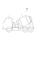
図1は、本発明の一実施形態に係るミキサ車を示す概略側面図である。図2は、上記ミキサ車におけるミキサドラムの駆動回路を示す概略構成図である。 FIG. 1 is a schematic side view showing a mixer truck according to an embodiment of the present invention. FIG. 2 is a schematic configuration diagram showing a mixer drum drive circuit in the mixer vehicle.
[ミキサ車の全体構成]
ミキサ車100は、モルタルやレディミクストコンクリート等(以下、「生コン」という。)を生コン工場から工事現場まで運搬するミキサドラム1を有する。ミキサドラム1は、ミキサ車100の架台2に回転自在に設置される。ミキサ車100は、生コンを運搬するに当たり、生コンの品質劣化および固化を防止するために、ミキサドラム1を正回転させてミキサドラム1内に取り付けられた螺旋状の複数のブレードで生コンを撹拌する。また、ミキサ車100は、ミキサドラム1を逆回転させることでミキサドラム1内の生コンを排出し、コンクリート打設箇所へ供給する。
[Overall configuration of mixer truck]
The
図1および図2に示すようにミキサ車100は、車体部10を有する。車体部10は、ミキサドラム1、架台2、エンジン3、発電機4、第1のバッテリ5、制御部6、キャビン7等を含む。
As shown in FIGS. 1 and 2, the
エンジン3は、ミキサ車100の動力源であり、ガソリンエンジン、ディーゼルエンジン等の内燃機関で構成される。発電機4は、エンジンの回転動力によって発電し、発電した電力を第1のバッテリ5および後述する第2のバッテリ21へ供給する。発電機4は1台に限られず、複数台備えられてもよい。この場合、複数の発電機で第1および第2のバッテリ5,21が充電されてもよいし、バッテリ毎に発電機が割り当てられてもよい。
The
第1のバッテリ5は、発電機4の出力(電力)を蓄電し、車体部10における電装系の電力源として用いられる。第1のバッテリ5は、例えば、2Vの単位セルを12個直列に接続した定格24Vの鉛蓄電池が用いられる。
The
制御部6は、典型的にはコンピュータで構成され、エンジン3の点火制御のほか、ミキサ車100の電装部品を電気的に制御する。
The
また、制御部6は、ミキサ車100が信号待ち等で停車した際、所定の条件下においてエンジン3の駆動を停止させるアイドリングストップ機能を実行する。所定の条件は適宜設定され、典型的には、アクセルペダルやブレーキペダル、サイドブレーキ(駐車ブレーキ)等の操作状態が参照される。制御部6は、アイドリングストップ機能を実行する際、第2の駆動回路52へアイドリングストップ信号を送信するように構成される。
Moreover, the
ミキサ車100においては、生コンを排出するまでは常にミキサドラム1を回転させる必要がある。そこで、ミキサ車100は、ミキサドラム1の駆動回路として、エンジン駆動時に稼動する第1の駆動回路51と、エンジン停止時に稼動する第2の駆動回路52とを備える。
In the
第1の駆動回路51は、その駆動源に、ミキサ車100のエンジン3が用いられる。第1の駆動回路51は、PTO(Power Take Off)を介してエンジン3の回転動力を第1の油圧ポンプ11(第1の液圧ポンプ)へ伝達し、第1の油圧ポンプ11から吐出される圧油(液体)を油圧モータ12(液圧モータ)へ供給してこれを駆動し、油圧モータ12の回転でミキサドラム1を回転駆動する。
The
第2の駆動回路52は、その駆動源に、第2のバッテリ21が用いられる。第2の駆動回路52は、第2のバッテリ21の放電出力で電動モータ22を駆動し、電動モータ22の回転動力を第2の油圧ポンプ23(第2の液圧ポンプ)へ伝達する。第2の油圧ポンプ23は圧油を油圧モータ12へ供給してこれを駆動し、油圧モータ12の回転でミキサドラム1を回転駆動する。
The
[第1の駆動回路]
続いて、第1の駆動回路51の詳細について説明する。
[First drive circuit]
Next, details of the
第1の駆動回路51は、第1の油圧ポンプ11と、油圧モータ12と、第1の制御弁13とを有する。第1の制御弁13は、第1の油圧ポンプ11と油圧モータ12との間に配置され、油圧モータ12と第1の制御弁13との間には油圧回路14が構成される。
The
第1の油圧ポンプ11は、エンジン3の動力で駆動され、油圧モータ12へ圧油を供給する。油圧モータ12は、第1の油圧ポンプ11から圧油の供給を受けてミキサドラム1を回転させる。
The first
第1の制御弁13は、第1の油圧ポンプ11から油圧回路14への圧油の供給およびその遮断、ならびに油圧回路14における圧油の供給方向を切り替える。第1の制御弁13は、A位置と、B位置と、C位置とを有する3位置4ポートの電磁切替弁で構成され、上記各位置は、制御部6から送信される制御信号に基づいて切り替えられる。
The
具体的に、第1の制御弁13は、ミキサドラム1を正方向に回転させるときはA位置に切り替えられ、ミキサドラムを逆方向に回転させるときはC位置に切り替えられる。また、第1の制御弁13は、第1の油圧ポンプ11から油圧モータ12への圧油の供給を遮断するときはB位置へ切り替えられる。
Specifically, the
なお図示せずとも、油圧回路14には、所定以上の油圧が発生したときに開弁するリリーフ弁や、圧油の供給方向を規制するチェック弁等が適宜の位置に設けられてもよい。また図示せずとも、油圧モータ12とミキサドラム1との間に減速機が設置されてもよい。
Although not shown, the
[第2の駆動回路]
第2の駆動回路52は、第2のバッテリ21と、電動モータ22と、第2の油圧ポンプ23と、第2の制御弁24と、放電制御部25とを有する。
[Second drive circuit]
The
第2の駆動回路52は、単一のユニット構造を有してもよい。この場合、第2の駆動回路52は、架台2上の適宜の位置に設置され、例えば図1に示すようにキャビン7と油圧モータ12との間に設置される。
The
第2のバッテリ21は、発電機4の出力(電力)を蓄電する蓄電池で構成され、電動モータ22の電力源として用いられる。第2のバッテリ21は、充放電可能な二次電池であれば特に限定されず、本実施形態では、3.7Vの単位セルを7個直列に接続した定格25.9Vのリチウムイオンバッテリが用いられる。
The
電動モータ22は、第2のバッテリ21の出力で駆動され、例えば、直流(DC)モータで構成される。電動モータ22は、後述するように、放電制御部25が上記アイドリングストップ信号を受信したときに、放電制御部25により放電制御された第2のバッテリ21の出力によって駆動される。
The
第2の油圧ポンプ23は、電動モータ22で駆動される。第2の油圧ポンプ23は、タンク26に貯留された作動油を吸引し、油圧回路14へ圧油を供給する。第2の油圧ポンプ23から吐出される圧油量は、電動モータ22の出力(回転数)によって制御される。第2の油圧ポンプ23は、油圧回路14において、油圧モータ12を正方向に回転させる方向に圧油を循環させる。
The second
第2の制御弁24は、第2の油圧ポンプ23と油圧回路14との間に配置される。第2の制御弁24は、第2の油圧ポンプ23から油圧回路14への圧油の供給およびその遮断を切り替える。第2の制御弁24は、D位置と、E位置とを有する2位置4ポート電磁切替弁で構成され、上記各位置は、制御部6から送信される制御信号に基づいて切り替えられる。
The
具体的に、第2の制御弁24は、エンジン3の駆動時はD位置に切り替えられ、第2の油圧ポンプ23と油圧回路14との間を遮断する。一方、第2の制御弁24は、後述するように、放電制御部25がアイドリングストップ信号を受信したときにE位置へ切り替えられるように構成される。E位置では、第2の油圧ポンプ23と油圧回路14との間を連通させ、油圧モータ12を正方向に回転させる方向に油圧回路14とタンク26との間で圧油を循環させる。
Specifically, the
放電制御部25は、制御部6からアイドリングストップ信号を受信したときに、第2のバッテリ21の充電量を検出し、上記充電量に応じて第2のバッテリ21の放電を制御するように構成される。
The
図3は、放電制御部25の機能ブロック図である。
FIG. 3 is a functional block diagram of the
放電制御部25は、受信部251と、検出部252と、出力調整部253と、コントローラ254とを有する。放電制御部25は、第2の駆動回路52の動作を制御する制御装置として構成される。
The
受信部251は、車体部10の制御部6と電気的に接続されており、制御部6からアイドリングストップ信号を受信することが可能に構成される。受信部251は、制御部6と有線で接続されているが、無線で接続されてもよい。
The receiving
検出部252は、第2のバッテリ21の充電状態を検出することが可能に構成される。本実施形態において検出部252は、第2のバッテリ21の充電量(SOC:State of Charge)を検出する。充電量は、第2のバッテリ21の満充電状態(あるいは初期容量)を100%としたときの残容量であり、電流積算によって測定されてもよいし、予め取得したバッテリ21のI−V特性データに基づいて判定されてもよい。
The
出力調整部253は、第2のバッテリ21と電動モータ22との間に配置され、第2のバッテリ21の放電出力を調整することが可能に構成される。本実施形態において出力調整部253は、複数のFET(Field Effect Transistor)等のスイッチング素子を有し、コントローラ254において決定された所定のデューティ比で第2のバッテリ21の放電出力(電圧)をパルス幅変調(PWM:Pulse Width Modulation)する。
The
コントローラ254は、受信部251を介してアイドリングストップ信号を受信したとき、検出部252を介して第2のバッテリ21の充電量を取得する。そしてコントローラ254は、第2のバッテリ21の充電量が所定値を超えているか否かを判定し、充電量が所定値を超えている場合は、当該充電量に応じたデューティ比を決定する。
When the
具体的に、コントローラ254は、第2のバッテリ21の充電量が所定値を超えているときは、当該充電量が高いほど低いデューティ比で第2のバッテリ21が放電するように出力調整部253を制御する。本実施形態においてコントローラ254は、第2のバッテリ21の充電量が上記所定値を超える場合には、上記所定値における放電出力で第2のバッテリ21が放電するように出力調整部253を制御する。
Specifically, when the charge amount of the
上記所定値は特に限定されず、典型的には、ミキサドラム1を目的とする回転数で回転させるのに必要な電力を出力することが可能な適宜の値に設定される。
The predetermined value is not particularly limited, and is typically set to an appropriate value capable of outputting electric power necessary to rotate the
この場合、上記所定値は、アイドリングストップ時においてミキサドラム1を所定の回転数で回転させるための基準電力に相当する電力を出力する充電量とされる。コントローラ254は、上記充電量が上記所定値を超えている場合は、上記基準電力に相当する出力が得られるデューティ比で第2のバッテリ21をパルス放電させる。
In this case, the predetermined value is a charge amount for outputting electric power corresponding to reference electric power for rotating the
アイドリングストップ時におけるミキサドラム1の回転数は特に限定されず、例えば、走行時におけるミキサドラム1の回転数よりも低い回転数に設定されてもよい。本実施形態では、エンジン駆動時は第1の回転数(例えば、毎分2回転)でミキサドラム1を回転させ、アイドリングストップ時は第2の回転数(例えば、毎分0.8〜1回転)でミキサドラム1を回転させる。
The rotation speed of the
デューティ比の制御範囲は特に限定されず、本実施形態では第2のバッテリ21の充電量(SOC)が50%以上100%以下の範囲でデューティ比が調整される。図4に、第2のバッテリ21の充電量(SOC)とそのパルス放電制御におけるデューティ比との関係の一例を示す。
The control range of the duty ratio is not particularly limited, and in this embodiment, the duty ratio is adjusted in a range where the charge amount (SOC) of the
図4に示すように、放電制御部25は、第2のバッテリ21の充電量(SOC)が50%を超える場合に、第2のバッテリ21をパルス放電させるように構成されている。これにより第2のバッテリ21が上記基準電力を超える出力で放電することを防止し、ミキサドラム1の回転動力の省エネルギ化を実現することができる。本例の場合、上記所定値は充電量50%であり、上記基準電力は、充電量50%に相当する出力電圧とされるが、勿論この例に限られない。
As shown in FIG. 4, the
また蓄電池は、一般に、充電量が高いほど大きな出力で放電する傾向にある。そこで放電制御部25は、充電量が高いほど低いデューティ比で第2のバッテリ21をパルス放電させるように構成される。本実施形態では、第2のバッテリ21の充電量が70%のときはデューティ比が95%となるように、また、上記充電量が100%のときはデューティ比が80%となるように、第2のバッテリ21の放電出力をパルス幅変調させる。図5Aにデューティ比90%での出力制御例を示す。
In general, the storage battery tends to discharge at a higher output as the charge amount is higher. Therefore, the
さらに放電制御部25は、第2のバッテリ21の充電量が50%を超え、かつ70%以下の範囲においては、第1の勾配で直線的にデューティ比を低下させ、上記充電量が70%を超え、かつ100%以下の範囲においては、上記第1の勾配よりも大きい第2の勾配でデューティ比を低下させる。これにより、充電量の大きさに依存せずにミキサドラム1を上記第2の回転数で安定に回転させることができる。
Further, the
上記第1および第2の勾配は特に限定されず、第2のバッテリ21を構成する蓄電池の放電特性に応じて適宜設定可能である。また、充電量に対するデューティ比の変化は直線的である場合に限られず、曲線的であってもよいし、階段状(ステップ状)であってもよい。
The first and second gradients are not particularly limited, and can be appropriately set according to the discharge characteristics of the storage battery constituting the
一方、第2のバッテリ21の充電量が上記所定値(充電量50%)以下の場合には、放電制御部25は、図4に示すように第2のバッテリ21の放電出力をデューティ比100%でパルス幅変調(連続放電)させるように構成される。これにより、ミキサドラムを上記第2の回転数あるいはそれ以下の回転数で回転させることができる。図5Bにデューティ比100%での出力制御例を示す。
On the other hand, when the charge amount of the
[ミキサ車および放電制御部の動作]
次に、以上のように構成されるミキサ車100および放電制御部25の典型的な動作について説明する。
[Operation of mixer truck and discharge controller]
Next, typical operations of the
ミキサドラム1に生コンを搭載したミキサ車100は、コンクリートプラントから打設現場までミキサドラム1を所定の回転数で正方向に回転させながら、ミキサドラム1内で生コンを撹拌する。
The
ここで、ミキサ車100の走行時においては、図2に示すように、第1の制御弁13はA位置にあり、第2の制御弁24はD位置にある。その結果、エンジン3を駆動源とする第1の駆動回路51により、ミキサドラム1が正方向に上記第1の回転数で回転される。また、ミキサ車100の走行中、発電機4により、第1のバッテリ5および第2のバッテリ21が充電される。
Here, when the
一方、信号待ち、渋滞等によってミキサ車100が停止し、所定のアイドリングストップ機能を実行する所期の条件(例えば、駐車ブレーキの作動等)を検出すると、制御部6は、アイドリングストップ機能を実行し、エンジン3の駆動を停止させる。制御部6はさらに、放電制御部25へアイドリングストップ信号を発信するとともに、第1の制御弁13をA位置からB位置へ、第2の制御弁24をD位置からE位置へそれぞれ切り替える。
On the other hand, when the
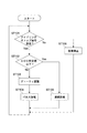
図6は、放電制御部25の動作を説明するフローチャートである。
FIG. 6 is a flowchart for explaining the operation of the
放電制御部25は、受信部251を介してアイドリングストップ信号を受信する。コントローラ254は、アイドリングストップ信号を受信すると、検出部252から第2のバッテリ21の充電量(SOC)を取得し、その充電量が所定値(SOC50%)を超えている否かを判定する(ST101,ST102)。
The
第2のバッテリ21の充電量が上記所定値を超えている場合、コントローラ254は、充電量に応じたデューティ比で出力調整部253において第2のバッテリ21の放電出力をパルス幅変調させる(ST103,104)。
When the charge amount of the
電動モータ22は、変調された第2のバッテリ21の出力によって回転し、第2の油圧ポンプ23は、電動モータ22の回転数に応じた圧油を油圧回路14へ吐出する。油圧モータ12は、第2の油圧ポンプ23から吐出された圧油で駆動され、ミキサドラム1を正方向に回転させる。これによりミキサドラム1の駆動源が、第1の駆動回路51から第2の駆動回路52へ切り替えられる。
The
本実施形態において、放電制御部25は、図4に示すように充電量が高いほど低いデューティ比で第2のバッテリ21をパルス放電させるように構成される。これにより、第2のバッテリ21の充電量が大きい場合でも必要以上の出力で第2のバッテリ21を放電させる必要がなくなるため、ミキサドラム1の回転動力の省エネルギ化を図ることが可能となる。
In the present embodiment, as shown in FIG. 4, the
また本実施形態においては、上記所定値が、アイドリングストップ時においてミキサドラム1を上記第2の回転数で回転させるための基準電力に相当する電力を出力する充電量とされ、放電制御部25は、上記基準電力に相当する出力が得られるデューティ比で第2のバッテリ21をパルス放電させる。これにより、第2のバッテリ21の充電量に依存せず、ミキサドラム1を目的とする回転数(第2の回転数)で安定に回転させることができるとともに、ミキサドラム1の回転動力の省エネルギ化を実現することができる。
In the present embodiment, the predetermined value is a charge amount that outputs power corresponding to the reference power for rotating the
一方、第2のバッテリ21の充電量が上記所定値以下の場合、コントローラ254は、第2のバッテリ21を連続放電させる(ST105)。これにより、ミキサドラム1を上記所定の回転数あるいはそれ以下の回転数で回転させることができる。この場合、第2のバッテリ21の充電量が所定値以下の場合であっても、生コンの撹拌に最低限必要なミキサドラム1の回転数が確保される。
On the other hand, when the charge amount of the
なお第2のバッテリ21の充電量が、生コンの撹拌に最低限必要なミキサドラム1の回転数を確保できないほど低い場合には、放電制御部25から制御部6へアイドリングストップ機能の実行中止を要求する信号を送信するよう構成されてもよい。
When the charge amount of the
運転者による車両走行操作(例えば、駐車ブレーキの解除等)を検出すると、制御部6は、第1の制御弁13をB位置からA位置へ、第2の制御弁24をE位置からD位置へそれぞれ切り替えた後、エンジン3を駆動する。そして制御部6は、放電制御部25へのアイドリングストップ信号の送信を停止する。これにより、放電制御部25においてコントローラ254は、出力調整部253における第2のバッテリ21の放電を停止させる(ST106)。これによりミキサドラム1の駆動源が、第2の駆動回路52から第1の駆動回路51へ切り替えられる。
When detecting a vehicle driving operation (for example, release of the parking brake) by the driver, the
以上のように本実施形態によれば、アイドリングストップ時においてもミキサドラム1を第2の回転数で安定に回転させることができる。また、ミキサドラム1が必要以上の回転数で回転することが防止され、ミキサドラム1の回転動力の省エネルギ化を実現することができる。
As described above, according to the present embodiment, the
また、第2のバッテリ21として、単位セルあたりの出力電圧が比較的高いリチウムイオンバッテリを用いる場合、その出力電圧を電動モータ22の駆動電圧に最適化することが困難な場合が多い。このような場合においても、本実施形態によれば、第2のバッテリ21の充電量に応じて放電出力を容易に調整することができ、電動モータ22を所望とする回転数で駆動させることができる。
Further, when a lithium ion battery having a relatively high output voltage per unit cell is used as the
しかも、電動モータ22がDCモータで構成されているため、回転数および回転トルクを入力電圧で容易に調整することができる。本実施形態によれば、目的とする電動モータの回転数および回転トルクが得られる電圧となるように第2のバッテリ21の放電出力を制御することができるため、ミキサドラム1内の生コンの量に依存せず安定した回転数でミキサドラム1を回転させることができる。
Moreover, since the
さらに本実施形態によれば、第2のバッテリ21の放電出力を高精度に制御することができるため、使用されるバッテリ容量と比較して最大定格が低い電動モータの使用も可能となるなど、電動モータ22の選択の幅を広げることができる。これにより、ミキサ車100あるいは第2の駆動回路52の設計自由度を向上させることが可能となる。
Furthermore, according to the present embodiment, since the discharge output of the
以上、本発明の実施形態について説明したが、本発明は上述の実施形態にのみ限定されるものではなく、本発明の要旨を逸脱しない範囲内において種々変更を加え得ることは勿論である。 The embodiment of the present invention has been described above, but the present invention is not limited to the above-described embodiment, and it is needless to say that various modifications can be made without departing from the gist of the present invention.
例えば以上の実施形態では、第2の駆動回路52における第2の制御弁24は、制御部6によって切り替え制御されるように構成されたが、これに代えて、放電制御部25におけるコントローラ254によって切り替え制御されてもよい。
For example, in the above embodiment, the
また、第2の駆動回路52における第2のバッテリ21は、リチウムイオンバッテリで構成されたが、ニッケル−水素蓄電池や鉛蓄電池等の他の二次電池が用いられてもよい。
Moreover, although the
さらに放電制御部25におけるコントローラ254は、発電機4から第2のバッテリ21への充電制御も行うように構成されてもよい。これにより、第2のバッテリ21の劣化を抑制しつつ、専用の充電制御回路を設ける必要をなくすことができる。
Furthermore, the
1…ミキサドラム
3…エンジン
4…発電機
5…第1のバッテリ
6…制御部
10…車体部
11…第1の油圧ポンプ
12…油圧モータ
21…第2のバッテリ
22…電動モータ
23…第2の油圧ポンプ
25…放電制御部
51…第1の駆動回路
52…第2の駆動回路
251…受信部
252…検出部
253…出力調整部
254…コントローラ
DESCRIPTION OF
Claims (4)
前記ミキサドラムを回転させる液圧モータと、前記エンジンの動力で駆動され前記液圧モータへ液体を供給する第1の液圧ポンプと、を有する第1の駆動回路と、
前記発電機の出力を蓄電する蓄電池と、前記蓄電池による放電で駆動される電動モータと、前記電動モータで駆動され前記液圧モータへ液体を供給する第2の液圧ポンプと、前記制御部からアイドリングストップ信号を受信したときに前記蓄電池の充電量を検出し、前記充電量が、前記ミキサドラムを所定の回転数で回転させるための基準電力に相当する電力を出力する充電量である所定値を超えているか否かを判定し、前記充電量が前記所定値を超えている場合は、前記充電量が高いほど低いデューティ比で前記蓄電池をパルス放電させ、前記充電量が前記所定値以下の場合は前記蓄電池を連続放電させる放電制御部と、を有する第2の駆動回路と
を具備するミキサ車。 A vehicle body portion including an engine, a generator that generates electric power by the engine, a control unit that controls the engine, and a mixer drum;
A first drive circuit comprising: a hydraulic motor that rotates the mixer drum; and a first hydraulic pump that is driven by the power of the engine and supplies liquid to the hydraulic motor;
A storage battery that stores the output of the generator; an electric motor that is driven by the discharge of the storage battery; a second hydraulic pump that is driven by the electric motor and supplies liquid to the hydraulic motor; A charge amount of the storage battery is detected when an idling stop signal is received, and the charge amount is a predetermined value that is a charge amount for outputting power corresponding to a reference power for rotating the mixer drum at a predetermined rotation speed. determines whether or not exceeded, if the charge amount exceeds the predetermined value, the charging amount is pulse discharge the battery at a higher low duty ratio, when the charge amount is less than the predetermined value mixer truck having a second drive circuit having a discharge control unit that Ru is continuously discharging the storage battery.
前記放電制御部は、前記充電量が前記所定値を超えている場合は、前記基準電力に相当する出力が得られるデューティ比で前記蓄電池をパルス放電させる
ミキサ車。 The mixer vehicle according to claim 1,
Before Symbol discharge control section, when the charge amount exceeds the predetermined value, mixer truck for pulse discharge the battery at a duty ratio output corresponding to the reference power is obtained.
前記制御部からアイドリングストップ信号を受信可能な受信部と、
前記蓄電池の充電量を検出する検出部と、
前記アイドリングストップ信号を受信したときに、検出された前記蓄電池の充電量が、前記ミキサドラムを所定の回転数で回転させるための基準電力に相当する電力を出力する充電量である所定値を超えているか否かを判定し、前記充電量が前記所定値を超えている場合は、前記充電量が高いほど低いデューティ比で前記蓄電池をパルス放電させ、前記充電量が前記所定値以下の場合は前記蓄電池を連続放電させるコントローラと
を具備する制御装置。 A generator that generates power using engine power, a control unit that controls the engine, a hydraulic motor that rotates a mixer drum, a storage battery that stores the output of the generator, and an electric motor that is driven by a discharge from the storage battery A hydraulic pump driven by the electric motor and supplying a liquid to the hydraulic motor, and a control device mounted on a mixer vehicle,
A receiving unit capable of receiving an idling stop signal from the control unit;
A detection unit for detecting a charge amount of the storage battery;
When the idling stop signal is received, the detected charge amount of the storage battery exceeds a predetermined value that is a charge amount for outputting power corresponding to reference power for rotating the mixer drum at a predetermined rotation speed. When the charge amount exceeds the predetermined value, the storage battery is pulse-discharged with a lower duty ratio as the charge amount is higher, and the charge amount is lower than the predetermined value when the charge amount is lower than the predetermined value. control apparatus comprising a controller Ru storage battery was continuously discharged.
前記蓄電池の充電量が、前記ミキサドラムを前記所定の回転数で回転させるための基準電力に相当する電力を出力する所定の充電量を超えているか否かを判定し、
前記充電量が前記所定の充電量を超えている場合は、前記基準電力に相当する出力が得られるデューティ比で前記蓄電池をパルス放電させ、
前記充電量が前記所定の充電量以下の場合は、前記蓄電池を連続放電させる
ミキサドラムの回転制御方法。 A mixer drum rotation control method for driving an electric motor by discharging by a storage battery at idling stop of a mixer car and rotating the mixer drum at a predetermined rotation speed by the output of the electric motor,
Determining whether or not a charge amount of the storage battery exceeds a predetermined charge amount for outputting electric power corresponding to a reference electric power for rotating the mixer drum at the predetermined rotational speed;
When the charge amount exceeds the predetermined charge amount, the storage battery is pulse-discharged at a duty ratio that provides an output corresponding to the reference power,
A mixer drum rotation control method for continuously discharging the storage battery when the charge amount is equal to or less than the predetermined charge amount.
Priority Applications (1)
| Application Number | Priority Date | Filing Date | Title |
|---|---|---|---|
| JP2014071383A JP6285246B2 (en) | 2014-03-31 | 2014-03-31 | Mixer vehicle, control device, and rotation control method of mixer drum |
Applications Claiming Priority (1)
| Application Number | Priority Date | Filing Date | Title |
|---|---|---|---|
| JP2014071383A JP6285246B2 (en) | 2014-03-31 | 2014-03-31 | Mixer vehicle, control device, and rotation control method of mixer drum |
Publications (2)
| Publication Number | Publication Date |
|---|---|
| JP2015193289A JP2015193289A (en) | 2015-11-05 |
| JP6285246B2 true JP6285246B2 (en) | 2018-02-28 |
Family
ID=54432767
Family Applications (1)
| Application Number | Title | Priority Date | Filing Date |
|---|---|---|---|
| JP2014071383A Expired - Fee Related JP6285246B2 (en) | 2014-03-31 | 2014-03-31 | Mixer vehicle, control device, and rotation control method of mixer drum |
Country Status (1)
| Country | Link |
|---|---|
| JP (1) | JP6285246B2 (en) |
Families Citing this family (7)
| Publication number | Priority date | Publication date | Assignee | Title |
|---|---|---|---|---|
| IT201800006841A1 (en) * | 2018-07-02 | 2020-01-02 | DRIVE APPARATUS OF A MOBILE OPERATING MACHINE AND A MOBILE OPERATING MACHINE INCLUDING THIS DRIVE APPARATUS | |
| CN110116458A (en) * | 2019-06-26 | 2019-08-13 | 三一专用汽车有限责任公司 | Drive system is filled on mixer truck, drive control method is filled on mixer truck |
| CN111591201A (en) * | 2020-05-22 | 2020-08-28 | 河北中瑞汽车制造有限公司 | Power system installed on mixer truck and control method thereof |
| CN113401037B (en) * | 2021-07-15 | 2023-02-17 | 三一专用汽车有限责任公司 | Power control method and controller for engineering machinery, power system and engineering machinery |
| CN113541400B (en) * | 2021-08-11 | 2022-09-06 | 郑州森鹏电子技术股份有限公司 | Concrete mixer truck and loading system thereof |
| CN113787618B (en) * | 2021-08-23 | 2023-01-31 | 三一汽车制造有限公司 | Mixing drum rotating speed control method and device and mixing truck |
| CN113894932B (en) * | 2021-09-16 | 2022-08-02 | 中联重科股份有限公司 | Control method and device for mixer truck, platform, controller and mixer truck |
Family Cites Families (5)
| Publication number | Priority date | Publication date | Assignee | Title |
|---|---|---|---|---|
| JPH06253415A (en) * | 1993-03-01 | 1994-09-09 | Toyota Autom Loom Works Ltd | Motor controller for battery-operated vehicle |
| JPH09201126A (en) * | 1995-11-24 | 1997-08-05 | Honda Motor Co Ltd | Electric mower |
| JP2003301802A (en) * | 2002-02-06 | 2003-10-24 | Kayaba Ind Co Ltd | Truck mixer agitator |
| JP4608987B2 (en) * | 2004-07-23 | 2011-01-12 | ソニー株式会社 | Motor drive circuit, motor drive method, and camera |
| CA2523240C (en) * | 2005-10-11 | 2009-12-08 | Delaware Systems Inc. | Universal battery module and controller therefor |
-
2014
- 2014-03-31 JP JP2014071383A patent/JP6285246B2/en not_active Expired - Fee Related
Also Published As
| Publication number | Publication date |
|---|---|
| JP2015193289A (en) | 2015-11-05 |
Similar Documents
| Publication | Publication Date | Title |
|---|---|---|
| JP6285246B2 (en) | Mixer vehicle, control device, and rotation control method of mixer drum | |
| US20110208378A1 (en) | Method for operating a hybrid vehicle | |
| US8504232B2 (en) | Electrically powered vehicle and method for controlling the same | |
| US8818603B2 (en) | Vehicle, control apparatus for vehicle, and control method for vehicle | |
| CN102220914B (en) | Multi-phase engine stop position controls | |
| KR20160078462A (en) | Vehicle battery pre-charge feature | |
| JP2008030682A (en) | Driving device of vehicle | |
| US20150352962A1 (en) | Hybrid vehicle | |
| US20070284164A1 (en) | Motor vehicle with electric boost motor | |
| CN102205788A (en) | Battery charging system for hybrid vehicles | |
| US20160318505A1 (en) | Control system for hybrid vehicle | |
| US10239416B2 (en) | System and method for improving reverse driving capability of electrified vehicles | |
| KR102274375B1 (en) | Method for managing the charge state of a traction battery of a hybrid vehicle | |
| KR102474514B1 (en) | Fail safe method for parallel hybrid electric vehicle | |
| JP5733198B2 (en) | Hybrid vehicle | |
| JP2013189161A (en) | Hybrid vehicle and electric power supply method for hybrid vehicle | |
| JP6527457B2 (en) | Control device for mixer car and mixer car | |
| JP6190610B2 (en) | Charge control device and mixer truck | |
| JP7373113B2 (en) | Vehicle power control device | |
| JP6410480B2 (en) | Mixer vehicle, control device, and rotation control method of mixer drum | |
| JP5273186B2 (en) | In-vehicle power supply device and power supply system | |
| JP5454796B2 (en) | Vehicle control device | |
| CN113451620A (en) | Fuel cell system, vehicle, and control method for fuel cell system | |
| WO2009083750A1 (en) | Hybrid vehicle with an equipment electrical power take off | |
| JP2017529035A (en) | Power management system with automatic calibration |
Legal Events
| Date | Code | Title | Description |
|---|---|---|---|
| A621 | Written request for application examination |
Free format text: JAPANESE INTERMEDIATE CODE: A621 Effective date: 20161220 |
|
| A977 | Report on retrieval |
Free format text: JAPANESE INTERMEDIATE CODE: A971007 Effective date: 20170824 |
|
| A131 | Notification of reasons for refusal |
Free format text: JAPANESE INTERMEDIATE CODE: A131 Effective date: 20170926 |
|
| A521 | Written amendment |
Free format text: JAPANESE INTERMEDIATE CODE: A523 Effective date: 20171124 |
|
| TRDD | Decision of grant or rejection written | ||
| A01 | Written decision to grant a patent or to grant a registration (utility model) |
Free format text: JAPANESE INTERMEDIATE CODE: A01 Effective date: 20180123 |
|
| A61 | First payment of annual fees (during grant procedure) |
Free format text: JAPANESE INTERMEDIATE CODE: A61 Effective date: 20180201 |
|
| R150 | Certificate of patent or registration of utility model |
Ref document number: 6285246 Country of ref document: JP Free format text: JAPANESE INTERMEDIATE CODE: R150 |
|
| LAPS | Cancellation because of no payment of annual fees |