JP6284809B2 - Accumulator conveyor - Google Patents
Accumulator conveyor Download PDFInfo
- Publication number
- JP6284809B2 JP6284809B2 JP2014081638A JP2014081638A JP6284809B2 JP 6284809 B2 JP6284809 B2 JP 6284809B2 JP 2014081638 A JP2014081638 A JP 2014081638A JP 2014081638 A JP2014081638 A JP 2014081638A JP 6284809 B2 JP6284809 B2 JP 6284809B2
- Authority
- JP
- Japan
- Prior art keywords
- conveyor
- downstream
- upstream
- container
- accumulation
- Prior art date
- Legal status (The legal status is an assumption and is not a legal conclusion. Google has not performed a legal analysis and makes no representation as to the accuracy of the status listed.)
- Active
Links
- 238000011144 upstream manufacturing Methods 0.000 claims description 71
- 238000009825 accumulation Methods 0.000 claims description 55
- 238000000034 method Methods 0.000 claims description 17
- 230000008569 process Effects 0.000 claims description 17
- 230000009467 reduction Effects 0.000 claims description 8
- 230000003247 decreasing effect Effects 0.000 claims description 2
- 230000032258 transport Effects 0.000 description 87
- 235000013361 beverage Nutrition 0.000 description 12
- 230000002159 abnormal effect Effects 0.000 description 5
- 238000011143 downstream manufacturing Methods 0.000 description 5
- XLYOFNOQVPJJNP-UHFFFAOYSA-N water Substances O XLYOFNOQVPJJNP-UHFFFAOYSA-N 0.000 description 5
- 230000005856 abnormality Effects 0.000 description 4
- 238000010438 heat treatment Methods 0.000 description 4
- 239000000945 filler Substances 0.000 description 3
- 238000009833 condensation Methods 0.000 description 2
- 230000005494 condensation Effects 0.000 description 2
- 238000012423 maintenance Methods 0.000 description 2
- 230000001954 sterilising effect Effects 0.000 description 2
- 238000004659 sterilization and disinfection Methods 0.000 description 2
- 238000004078 waterproofing Methods 0.000 description 2
- 230000008901 benefit Effects 0.000 description 1
- 238000001816 cooling Methods 0.000 description 1
- 230000000694 effects Effects 0.000 description 1
- 238000002372 labelling Methods 0.000 description 1
- 238000004519 manufacturing process Methods 0.000 description 1
- 239000000463 material Substances 0.000 description 1
- 238000005507 spraying Methods 0.000 description 1
Images

Landscapes
- Control Of Conveyors (AREA)
- Attitude Control For Articles On Conveyors (AREA)
Description
本発明は、搬送されている物品を蓄積(アキューム)するアキュームコンベヤ装置に関する。 The present invention relates to an accumulation conveyor device that accumulates (accumulates) articles being conveyed.
飲料を容器に充填する飲料充填ラインにおいて、低温で充填された飲料が周囲の湿った高温の雰囲気に接触して表面に結露が生じると、結露水によって容器の表面にラベルを貼り付けるのに支障をきたしたり、また、飲料が充填された容器を段ボールケースに梱包する場合には、段ボールケースが結露水により破損したりすることがある。
従来、容器の表面に結露するのを防止するために、低温の飲料が充填された容器を連続搬送中に加温する加熱装置(ウォーマ)、あるいは、低温の飲料が充填された容器を連続搬送中に加温殺菌後冷却する加熱殺菌装置(パストライザ)が用いられる(例えば、特許文献1)。
In a beverage filling line that fills containers with beverages, if the beverage filled at low temperature comes into contact with the surrounding moist and hot atmosphere and condensation forms on the surface, it will hinder the labeling on the surface of the container with condensed water. In addition, when a container filled with a beverage is packed in a cardboard case, the cardboard case may be damaged by condensed water.
Conventionally, in order to prevent condensation on the surface of the container, a heating device (warmer) for heating a container filled with a low-temperature beverage during continuous conveyance, or a container filled with a low-temperature beverage is continuously conveyed. A heat sterilization apparatus (a pasterizer) that cools after heating and sterilization is used (for example, Patent Document 1).
容器に飲料を充填して製品を得る同じ飲料充填ラインにおいて、飲料が低温で充填される製品に限らず、飲料が常温以上の温度で充填される製品を製造することもある。この飲料充填ラインは、常温以上の温度で充填される製品を製造する際には、ウォーマ、パストライザを機能させずに、搬送コンベヤとして利用することができる。そこで、特許文献2は、容器処理装置の搬送コンベヤと排出コンベヤとの間にアキュームコンベヤを設けた容器処理システムを、容器処理装置での処理を必要としない容器の高速搬送に兼用することを提案している。
In the same beverage filling line in which a beverage is filled in a container to obtain a product, the product is not limited to a product in which a beverage is filled at a low temperature, but a product in which a beverage is filled at a temperature higher than room temperature may be manufactured. This beverage filling line can be used as a transport conveyor without producing a warmer and a pasterizer when manufacturing a product filled at a temperature higher than room temperature. Therefore,
特許文献2の容器処理装置は、容器処理装置の内部に設けられる搬送コンベヤが、独立して駆動され、搬送方向に区分される複数のコンベヤにより構成される。この容器処理装置は、処理を行わずに容器を搬送する際には、下流側のアキュームコンベヤに容器が満たされた後に搬送コンベヤまで容器が蓄積されると、搬送コンベヤの各コンベヤを容器の蓄積状態に応じて下流側から順次減速および停止させて、搬送コンベヤの各コンベヤに容器をアキュームさせる。
特許文献2の容器処理装置は、その搬送コンベヤをアキュームコンベヤとして利用できる利点を有するものの、搬送コンベヤを複数に区分している。容器処理装置、例えばウォーマは搬送方向の寸法が長く長尺であり、それを複数に区分すると、区分されたコンベヤに加えてこのコンベヤごとに電動モータを含む駆動系が必要となる。ウォーマは、通常、温水槽から温水を搬送される容器に散布するものであり、搬送コンベヤは単一の駆動系により駆動される。コンベヤ及び駆動系には散布される温水に対する防水を施す必要があるが、コンベヤ及び駆動系の区分数が多くなると、コンベヤ及び駆動系に防水を施すのに必要なコストが高くなり、また、そのメンテナンスの負担も大きくなる。
The container processing apparatus of
Although the container processing apparatus of
長尺の搬送コンベヤを複数に区分するのは、以下の理由による。
搬送方向に並ぶ複数のコンベヤを下流側から順次減速および停止させる従来の容器のアキューム動作を行うと、個々のコンベヤにおいて、下流側から上流側に向けて容器が接しながら順に蓄積される。したがって、アキュームの過程において、最も下流側に位置する容器、つまり先頭の容器は、下流側ですでに停止しているコンベヤのもっとも上流側に位置する容器、つまり後尾があるためにそこで搬送が止められる。アキュームの進行に伴って、先頭の容器には次の列の容器が接触し、さらにその次の列の容器が接触するということが繰り返される。コンベヤは駆動し続けているので、搬送が止められた容器はコンベヤから摩擦力を受けるので、先頭の容器はそれよりも上流側に位置する容器から搬送方向に向けて圧力を受けることになる。この圧力は、先頭の容器よりも上流側に存在する容器の数が多いほど、換言するとコンベヤの搬送方向の長さが長くなるほど大きくなる。例えば、容器がベットボトルのように可撓性の材料から形成されていると、この圧力により先頭の容器変形するおそれがある。そこで、先頭の容器が受ける圧力をできるだけ減らすために、長尺の搬送コンベヤを複数に区分して個々のコンベヤの長さを短くすることが必要である。したがって、従来のアキューム動作に従うと、先頭の容器に変形を与えることなく長尺な搬送コンベヤに容器をアキュームすることは難しい。
本発明は、このような課題に基づいてなされたもので、長尺の搬送コンベヤにアキューム機能を付与しながらも、先頭の容器、その他の物品が受ける圧力を低減できるアキュームコンベヤ装置を提供することを目的とする。
The long conveyor is divided into a plurality of reasons for the following reasons.
When a conventional container accumulating operation in which a plurality of conveyors arranged in the transport direction are sequentially decelerated and stopped from the downstream side is performed, the containers are sequentially accumulated while being in contact with each conveyor from the downstream side toward the upstream side. Therefore, during the accumulation process, the container located at the most downstream side, that is, the first container, stops transporting there because there is a container located at the most upstream side of the conveyor already stopped at the downstream side, that is, the tail. It is done. As the accumulation proceeds, it is repeated that the container in the next row comes into contact with the top container, and further, the container in the next row comes into contact. Since the conveyor continues to be driven, the containers that have stopped being transported receive frictional force from the conveyor, so that the leading container receives pressure in the transport direction from the container located on the upstream side. This pressure increases as the number of containers existing upstream from the first container increases, that is, as the length of the conveyor in the transport direction increases. For example, if the container is formed of a flexible material such as a bed bottle, the leading container may be deformed by this pressure. Therefore, in order to reduce the pressure received by the first container as much as possible, it is necessary to divide the long conveying conveyor into a plurality of parts and shorten the length of each conveyor. Therefore, according to the conventional accumulating operation, it is difficult to accumulate the container on the long conveying conveyor without deforming the leading container.
The present invention has been made based on such a problem, and provides an accumulation conveyor device capable of reducing the pressure received by a leading container and other articles while providing an accumulation function to a long conveyor. With the goal.
かかる目的のもとになされた本発明のアキュームコンベヤ装置は、物品の搬送方向の下流側に位置する第1下流側コンベヤと、第1下流側コンベヤよりも上流側に位置する上流側コンベヤと、を備え、物品が搬送されている最中に物品を第1下流側コンベヤ及び上流側コンベヤにアキュームするアキュームコンベヤ装置であって、第1下流側コンベヤ及び上流側コンベヤにおいて物品のアキューム動作が始まると、上流側コンベヤから第1下流側コンベヤに物品を移送しつつ、上流側コンベヤの上流側から下流側に向けて物品のアキュームを進める、ことを特徴とする。
本発明のアキュームコンベヤ装置は、上流側コンベヤから第1下流側コンベヤに物品を移送しつつ、上流側コンベヤの上流側から下流側に向けて物品のアキュームを進めるので、上流側コンベヤの先頭の容器が第1下流側コンベヤの後尾の容器により搬送が停止されることがない。しかも、上流側コンベヤの上流側から下流側に向けて物品のアキュームを進めるので、先頭の容器がそれよりも上流側に位置する容器から圧力を受けるのを抑えることができる。
The accumulation conveyor device of the present invention made for this purpose includes a first downstream conveyor located on the downstream side in the conveying direction of articles, an upstream conveyor located upstream from the first downstream conveyor, An accumulator device for accumulating articles to the first downstream conveyor and the upstream conveyor while the articles are being conveyed, and when the accumulating operation of the articles starts in the first downstream conveyor and the upstream conveyor The article is accumulated from the upstream side to the downstream side of the upstream conveyor while transferring the article from the upstream conveyor to the first downstream conveyor.
The accumulation conveyor apparatus of the present invention advances the accumulation of articles from the upstream side of the upstream conveyor toward the downstream side while transferring the articles from the upstream conveyor to the first downstream conveyor. However, the conveyance is not stopped by the rear container of the first downstream conveyor. In addition, since the accumulation of the articles is advanced from the upstream side of the upstream conveyor toward the downstream side, it is possible to suppress the leading container from receiving pressure from the container located on the upstream side.
本発明のアキュームコンベヤ装置において以上のようにアキューム動作を行うためには、アキューム動作が始まると、上流側コンベヤの物品の搬送速度を減速させる第1ステップを行い、続いて、第1下流側コンベヤの搬送速度を、第1ステップにおいて減速された上流側コンベヤの搬送速度未満とする第2ステップを行う。 In order to perform the accumulating operation as described above in the accumulating conveyor device of the present invention, when the accumulating operation is started, the first step of reducing the conveying speed of the articles on the upstream conveyor is performed, and then the first downstream conveyor the conveying speed of, intends row a second step of less than the conveying speed of the decelerated upstream conveyor in a first step.
本発明のアキュームコンベヤ装置において、上流側コンベヤを物品が搬送される過程で、物品に所定の処理が施される処理モードと、上流側コンベヤを物品が搬送される過程で、物品に所定の処理が施されない通過モードと、のいずれか一方が実行される場合に、処理モード及び通過モードの一方又は双方において、物品が搬送されている最中に物品を第1下流側コンベヤ及び上流側コンベヤにアキュームすることができる。 In the accumulation conveyor device according to the present invention, a processing mode in which a predetermined process is performed on the article in the process of conveying the article on the upstream conveyor, and a predetermined process on the article in the process of conveying the article on the upstream conveyor. When one of the processing mode and the passing mode is executed, the article is transferred to the first downstream conveyor and the upstream conveyor when one of the processing mode and the passing mode is executed. Can be accumulated.
本発明のアキュームコンベヤ装置において、上流側コンベヤは、物品の搬送方向の長さが、第1下流側コンベヤよりも長くすることができる。本発明によると、この場合でも、先頭の容器がそれよりも上流側に位置する容器から圧力を受けるのを避けることができる。例えば、上流側コンベヤは第1下流側コンベヤよりも2倍以上の長さにすることができる。 In the accumulation conveyor device of the present invention, the length of the upstream conveyor in the conveying direction of the articles can be made longer than that of the first downstream conveyor. According to the present invention, even in this case, it is possible to avoid that the leading container receives pressure from the container located on the upstream side. For example, the upstream conveyor can be more than twice as long as the first downstream conveyor.
本発明のアキュームコンベヤ装置において、第1下流側コンベヤよりも搬送方向の下流側にさらに第2下流側コンベヤを備えることができる。この場合、第1ステップにおいて、第1下流側コンベヤの搬送速度を、上流側コンベヤの搬送速度の第1ステップにおける減速比と等しくなるように減速し、第2下流側コンベヤの搬送速度を、上流側コンベヤの搬送速度よりも、上流側コンベヤの減速比以上の速度とすることができる。このように、第2下流側コンベヤを設けることで、上流側コンベヤからの容器の移送を第1下流側コンベヤが受けることを担保できる。
ここで、下流側コンベヤとして第1及び第2の2つを示しているが、本発明は3以上の複数の下流側コンベヤを設けることができる。この場合の下流側コンベヤの設置数は、上流側コンベヤの機長(搬送方向の長さ)と搬送速度との関係、及び、下流側コンベヤの機長と搬送速度との関係より、必要なアキューム時間を定めることにより求めることができる。
The accumulation conveyor apparatus of this invention WHEREIN: A 2nd downstream conveyor can be further provided in the downstream of a conveyance direction rather than a 1st downstream conveyor. In this case, in the first step, the conveyance speed of the first downstream conveyor is reduced to be equal to the reduction ratio in the first step of the conveyance speed of the upstream conveyor, and the conveyance speed of the second downstream conveyor is increased to the upstream. It can be set to a speed equal to or higher than the reduction ratio of the upstream conveyor than the conveyance speed of the side conveyor. Thus, by providing a 2nd downstream conveyor, it can ensure that the 1st downstream conveyor receives the transfer of the container from an upstream conveyor.
Here, although the 1st and 2nd two are shown as a downstream conveyor, this invention can provide the 3 or more several downstream conveyor. In this case, the number of downstream conveyors installed depends on the relationship between the length of the upstream conveyor (length in the transport direction) and the transport speed, and the relationship between the length of the downstream conveyor and the transport speed. It can be determined by setting.
本発明のアキュームコンベヤ装置によると、上流側コンベヤ及び第1下流側コンベヤにおいて物品のアキューム動作が始まると、上流側コンベヤから第1下流側コンベヤに物品を移送しつつ、上流側コンベヤの上流側から下流側に向けて物品のアキュームを進める、つまり、上流側コンベヤ及び第1下流側コンベヤの動作を連動させることにより、長尺な搬送コンベヤにアキューム機能を付加しながらも、搬送コンベヤにおける先頭の容器が後続の容器から圧力を受けるのを低減できる。 According to the accumulation conveyor device of the present invention, when the accumulation operation of the articles starts in the upstream conveyor and the first downstream conveyor, the articles are transferred from the upstream conveyor to the first downstream conveyor, and from the upstream side of the upstream conveyor. Advancing the accumulation of articles toward the downstream side, that is, by linking the operations of the upstream conveyor and the first downstream conveyor, while adding the accumulation function to the long conveyor, the leading container in the conveyor Can be reduced from receiving pressure from subsequent containers.
以下、添付図面に示す実施の形態に基づいて本発明を詳細に説明する。
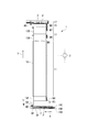
本実施の形態に係る容器処理システム1は、図1に示すように、上流側に設けられシステム、例えば図示を省略するフィラ(充填機)により例えば飲料が充填された後に、キャッパ(打栓機)によりキヤッビングがなされた容器Pを受け入れて、処理装置10により所定の処理を施した後に、下流側に設けられる処理システムに移送する。容器処理システム1は、以下に説明する各要素の動作を制御する制御部2を備えている。
処理装置10は、図1に示すように、搬送方向Yの上流側から下流側に亘って容器Pを搬送する搬送コンベヤ(上流側コンベヤ)11を備えており、この搬送コンベヤ11は、処理装置10よりも下流側に設けられる補助コンベヤ13と連動することにより、アキューム機能が付加される。処理装置10としては、例えば、ウォーマ、パストライザ、クーラなどが適用される。
容器処理システム1は、搬送されてくる容器Pを処理装置10において所定の処理を施す場合(処理モード)と、容器Pの処理を施すことなく処理装置10を通過して、下流システムに向けて搬送する場合(通過モード)の二種類の運転モードを備える。運転モードの選択は制御部2により行われる。
Hereinafter, the present invention will be described in detail based on embodiments shown in the accompanying drawings.
As shown in FIG. 1, the
As shown in FIG. 1, the
The
以下、容器処理システム1を構成する各要素について説明した後に、処理装置10におけるアキューム動作を説明する。
容器処理システム1は、処理装置10よりも上流側に供給コンベヤ3と、移送コンベヤ5と、を備えている。なお、容器処理システム1は、容器Pの搬送手段として複数種のコンベヤ装置を備えているが、特に言及しない限り、各々コンベヤ装置は、各々に対応して個別に設けられる電動モータにより独立して駆動されるようになっている。
Hereinafter, after explaining each element which comprises the
The
[供給コンベヤ3]
供給コンベヤ3は、処理装置10における搬送方向Yと直交する方向Xに沿って、キャッパから排出される容器Pを移送コンベヤ5まで搬送する。供給コンベヤ3を搬送される多数の容器Pは、密着した状態でランダムに搬送される。
供給コンベヤ3は、その幅方向(搬送方向Yと一致)に隣接して配置される2つの供給コンベヤ3A、3Bを備えており、供給コンベヤ3A、3Bは、各々、電動モータM1,M2により駆動される。供給コンベヤ3上で容器Pの滞留が発生せず、移送コンベヤ5上において、容器Pが幅方向に広がって乗り移るように、電動モータM1,M2の設定がなされている。なお、この搬送の速度は、処理モードにおける速度であり、以下で説明する搬送速度も、断りがない限り、処理モードにおける速度とする。
供給コンベヤ3上には、この供給コンベヤ3によって搬送されてきた容器Pを、移送コンベヤ5に乗り移らせるためのガイド19A、19B、19Cが設けられている。三つのガイド19A、19B、19Cは、ガイド19Bを中央に挟み、かつ、ガイド19A、19Cの各々をガイド19Bから間隔をあけて設けることにより、供給コンベヤ3を搬送されてきた容器Pを、ガイド19Bを境にして二列に区分して移送コンベヤ5に受け渡す。なお、ここで示す二列は例示に過ぎず、本発明は一列又は三列以上にすることを許容する。一般的には、容器Pの強度が弱い場合、あるいは、コンベヤの幅が広い場合には、列数を多くする傾向にある。ガイドの数は、列数に応じて定められる。
[Supply conveyor 3]
The
The
On the
[移送コンベヤ5]
移送コンベヤ5は、供給コンベヤ3で搬送されてきた容器Pを受け取って、処理装置10の搬送コンベヤ11に移送する。移送コンベヤ5は、供給コンベヤ3に比べて幅広とされており、容器Pを搬送方向Yに沿って搬送する。
移送コンベヤ5は、搬送方向Yに沿って、上流側に設けられる移送コンベヤ5Aと、下流側に設けられる移送コンベヤ5Bを備えている。移送コンベヤ5Aは電動モータM3により駆動され、移送コンベヤ5Bは電動モータM4により駆動される。移送コンベヤ5Aは一例として供給コンベヤ3よりも速い速度で駆動される。また、移送コンベヤ5Bは、移送コンベヤ5Aよりも遅い速度で運転され、その速度は容器処理システム1の能力を定める。
[Transport conveyor 5]
The
The
[搬送コンベヤ11]
容器処理システム1は、移送コンベヤ5の下流側に設けられ、処理装置10に対応する搬送コンベヤ11を備えている。搬送コンベヤ11は、処理モードにおいては、処理装置10における適宜の処理に適合するように容器Pを搬送する機能に加え、補助コンベヤ13と連動することにより、アキュームコンベヤとしての機能を有する。
搬送コンベヤ11は、移送コンベヤ5と幅が一致するとともに、処理装置10における容器Pの処理に必要な搬送方向Yの長さを有するように、例えば10m以上の長尺に構成されている。一方、補助コンベア13(13A,13B)の長さは、例えば1〜2m程度である。本実施形態における搬送コンベア11は補助コンベア13の4倍程度の長さを有している。
搬送コンベヤ11は、電動モータM5により駆動される単一のコンベヤ装置により構成される。この搬送コンベヤ11は、搬送する多数の容器Pを適切な時間だけ処理装置10内に滞在するように設定される。
[Conveyor 11]
The
The
The
本実施形態における処理装置10としては、ウォーマ、パストライザのように加熱を伴う処理、あるいは、クーラのように冷却を伴う処理など、任意の処理機能を有する装置が適用できる。容器Pは、搬送コンベヤ11により搬送されながら任意の処理が施されてから、処理装置10を通過する。
As the
[補助コンベヤ13]
容器処理システム1は、処理装置10(搬送コンベヤ11)の下流側に、補助コンベヤ13を備えている。補助コンベヤ13は、搬送コンベヤ11から受け渡される容器Pを、下流システムに搬送するための移送コンベヤ15に移送する機能を有するのに加えて、搬送コンベヤ11と連動することにより、アキュームコンベヤとしての機能をも有する。
[Auxiliary conveyor 13]
The
補助コンベヤ13は、幅が搬送コンベヤ11と同じ幅広であるが、長さ(搬送方向Yの寸法)は搬送コンベヤ11に比べて短尺に構成されている。
補助コンベヤ13は、上流側に設けられる第1補助コンベヤ(第1下流側コンベヤ)13Aと、下流側に設けられる第2補助コンベヤ(第2下流側コンベヤ)13Bを備えている。第1補助コンベヤ13Aは電動モータM6により駆動され、補助コンベヤ13は電動モータM7により駆動される。ここでは、第1補助コンベヤ13Aと第2補助コンベヤ13Bは、搬送方向Yの長さが等しくされている。
The
The
補助コンベヤ13を構成する第1補助コンベヤ13A,13Bは、通常の容器Pの処理を行う処理モードの際には、処理装置10の搬送コンベヤ11の搬送速度よりも概ね2〜20倍程度だけ速い速度で容器Pを搬送するように運転される。
The first
[移送コンベヤ15]
容器処理システム1は、補助コンベヤ13の下流側に、補助コンベヤ13によって搬送されてきた容器Pを排出コンベヤ17に受け渡す移送コンベヤ15が設けられている。この移送コンベヤ15は、一例として、移送コンベヤ5、搬送コンベヤ11および補助コンベヤ13よりも少し幅広に構成されている。移送コンベヤ15は電動モータM8によって、低速、例えば、搬送コンベヤ11と同等以上の搬送速度で運転される。
[Transport conveyor 15]
The
[排出コンベヤ17]
容器処理システム1は、移送コンベヤ15の下流側に、移送コンベヤ15と直交する方向Xに容器Pを搬送する排出コンベヤ17が配置されている。この排出コンベヤ17は、移送コンベヤ15から受け取った容器Pを搬送して、図示を省略する下流システムに向けて搬送する。この排出コンベヤ17は電動モータM9により高速で運転される。
[Discharge conveyor 17]
In the
[容器処理システム1の動作]
以上の構成を備える容器処理システム1の動作について、図2〜図5を参照して、処理装置10において容器Pの処理を行わない通過モード、容器Pの処理を行う処理モードの順に説明する。通過モードについては、下流側の処理システムが正常な運転を続けている通常運転について説明し、その後に、下流側の処理システムに停止などの異常が生じたために、搬送コンベヤ11にアキューム機能を発揮させる異常運転について説明する。
[Operation of container processing system 1]
Operation | movement of the
[通過モード(通常運転)]
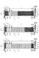
通過モードについて、図2(a)を参照して説明する。
通過モードにおいては、図示を省略するフィラーにより内容物が充填された後にキャッパでキャッピングが行われた容器Pが供給コンベヤ3によって搬送される。搬送される容器Pは、供給コンベヤ3から移送コンベヤ5に亘って設けられたガイド19A,19B,19Cに案内されて、供給コンベヤ3から移送コンベヤ5に受け渡される。
[Passing mode (normal operation)]
The passing mode will be described with reference to FIG.
In the passing mode, the container P that has been capped with a capper after the contents are filled with a filler (not shown) is conveyed by the
移送コンベヤ5Aにおいて、容器Pは幅方向に広がって搬送されるようにガイド19A,19B,19Cの形状及び電動モータM1〜M3の速度の設定がなされている。移送コンベヤ5Aよりも下流側の移送コンベヤ5Bは、移送コンベヤ5Aよりも搬送速度が遅いので、容器Pは移送コンベヤ5Aよりも密な分布となって搬送される。
In the
供給コンベヤ3から送られてきた容器Pは、移送コンベヤ5を介して処理装置10に搬入される。処理装置10内には、移送コンベヤ5Bから容器Pを受け渡される搬送コンベヤ11が配置されており、容器Pの処理を行わない通過モードのときには、処理装置10の搬送コンベヤ11も補助コンベヤ13と同様の高速で駆動するようにすることにより、処理モードに比べて数多くの容器Pを高速で搬送することができる。
The containers P sent from the
処理装置10を通過した容器Pは、搬送コンベヤ11の下流側に設けられる補助コンベヤ13に受け渡される。補助コンベヤ13は搬送コンベヤ11よりも高速で駆動されているので、補助コンベヤ13に受け渡された容器Pは、搬送コンベヤ11よりも搬送方向Yの分布が粗となって搬送される。
The containers P that have passed through the
補助コンベヤ13を搬送された容器Pは、移送コンベヤ15に乗り移った後に、移送コンベヤ15と直交する方向に配置された排出コンベヤ17に受け渡されて、下流処理システムに向けて搬送される。移送コンベヤ15は補助コンベヤ13よりも搬送速度が低速であるから、容器Pは移送コンベヤ15において搬送方向Yの分布が密となった後に排出コンベヤ17に受け渡される。
The container P transported on the
[通過モード(異常運転)]
通過モードにおいて、図2(a)に示すように、容器Pを搬送している最中に、容器処理システム1よりも下流側の処理システムが、何らかの原因により停止することがある。この時には、図2(b),(c)、図3、図4を参照して以下に説明するように、搬送コンベヤ11及び補助コンベヤ13に容器Pをアキュームすることにより、容器処理システム1よりも上流側の処理装置(フィラ、キャッパ等)の運転を停止させないか、停止させたとしても最小限に抑えることができる。
[Passing mode (abnormal operation)]
In the passing mode, as shown in FIG. 2A, the processing system downstream of the
[下流システム停止]
容器処理システム1が正常運転している最中に、下流システムが停止したものとすると、制御部2は、下流システムが停止したことを検知して、容器処理システム1の運転を以下のように制御する。なお、通常運転時における、各コンベヤの搬送速度Vは、以下の通りとする。ここで、搬送速度Vは、隙間なく接触させながら容器Pを搬送できる速度をいう。
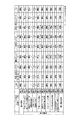
なお、図5に、各コンベヤ、上流システム及び下流システムの運転状態、搬送速度を示しているので、必要に応じて参照願いたい。また、以下に示す搬送速度はあくまで一例にすぎず、その趣旨に反しない限り、他の速度で運転することもできる。
移送コンベヤ5B=V 搬送コンベヤ11=3V
第1,2補助コンベヤ13A,13B=6V 移送コンベヤ15=V
[Downstream system stop]
Assuming that the downstream system is stopped while the
In addition, since the operation state and conveyance speed of each conveyor, an upstream system, and a downstream system are shown in FIG. 5, please refer as needed. Moreover, the conveyance speed shown below is only an example, and it can be operated at other speeds as long as it does not contradict the purpose.
First and second
[アキューム開始(図2(b),(c))]
下流システムの運転が停止されると、まず、制御部2は、移送コンベヤ15を停止させて、下流システムへ容器Pが供給されるのを阻止する。
また、制御部2は、容器Pの搬送速度を、第1補助コンベヤ13Aは6Vから2Vに下げ、第2補助コンベヤ13Bは6VからV/3に下げるとともに、搬送コンベヤ11は3VからVに下げる(第1ステップ)ことで、アキューム動作を開始する。ここで、搬送コンベヤ11における搬送速度の減速比は1/3(V/3V)であり、第1補助コンベヤ13Aは、この減速比と等しくなるように搬送速度が減速(6V×1/3)される。また、第2補助コンベヤ13Bは、搬送コンベヤ11の減速後の搬送速度よりも、この減速比以上の搬送速度(V×1/3以上)とされる。
第1補助コンベヤ13A及び第2補助コンベヤ13Bについてみると、このアキューム動作は、図2(b)に示すように、下流側の第2補助コンベヤ13Bで先行して容器Pのアキュームが進行する。このとき、第2補助コンベヤ13Bは、第1補助コンベヤ13Aの搬送速度が2Vまで下げられているのに対応して、搬送速度がV/3まで下げられているので、容器Pは搬送方向Yに上流側より密着しながら搬送される。第1補助コンベヤ13Aは、搬送コンベヤ11から受け渡される容器Pをアキュームが進行する第2補助コンベヤ13Bに搬送するが、搬送速度が2Vであるために、容器Pは搬送方向Yに間隔をあけたままで搬送される。
搬送コンベヤ11においては、搬送速度がVまで下げられており、容器Pの搬送能力が通常運転に比べて下がるために、容器Pは上流側から搬送方向Yの間隔が狭くなり、アキュームが進行する。また、搬送コンベヤ11の下流側においては、粗な分布で容器Pが搬送されている第1補助コンベヤ13Aに容器Pが移送される。このように、搬送コンベヤ11と第1補助コンベヤ13Aとが連動しているために、搬送コンベア11の下流側においては、容器Pの搬送方向Yの間隔が保たれたまま推移する。
第1補助コンベヤ13A,13B及び搬送コンベヤ11におけるこれらの搬送速度(以下にまとめて示す)は、第2補助コンベヤ13Bにアキュームし得る最大の本数(満杯)の容器Pがアキュームされ、第2補助コンベヤ13Bのアキュームが完了する図2(c)の状態になるまで継続される。
移送コンベヤ5B=V 搬送コンベヤ11=V
第1,2補助コンベヤ13A,13B=2V,V/3 移送コンベヤ15=0(停止)
[Accumulation start (FIGS. 2B, 2C)]
When the operation of the downstream system is stopped, the
In addition, the
As for the first
In the
The transfer speeds of the first
First and second
[アキューム進行(図2(c),図3(a))]
制御部2は、図2(c)に示される第2補助コンベヤ13Bの満杯状態を検知すると、第1補助コンベヤ13A,13B及び搬送コンベヤ11の搬送速度を以下のように変更し、さらに容器Pのアキュームを進める。
容器Pが満杯状態の第2補助コンベヤ13Bは停止させるとともに、第1補助コンベヤ13Aは搬送速度を2VからV/3に下げる(第2ステップ)。また、搬送コンベヤ11の搬送速度はVのまま維持する。
これにより、第1補助コンベヤ13Aにおいて、容器Pは搬送方向Yに上流側より密着しながら搬送され、時間の経過とともにアキュームが進行する。一方で、搬送コンベヤ11においては、アキュームが進行し、搬送方向Yに容器Pの間隔の狭い領域が時間の経過とともに上流側から下流側に向けて広がる。
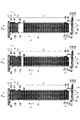
第1補助コンベヤ13A,13B及び搬送コンベヤ11におけるこれらの搬送速度(以下にまとめて示す)は、第1補助コンベヤ13Aに容器Pが満杯になり、かつ、搬送コンベヤ11に容器Pが満杯になりアキュームが完了する状態(図3(a))まで継続される。この図3(a)の状態は、上流システムの容器Pの払い出しが完了するのと一致させることができる。
以上の通りであり、本実施形態は、第1補助コンベヤ13Aにおけるアキューム動作と、搬送コンベヤ11におけるアキューム動作とが、並行して行われる期間を有している。このように、搬送コンベヤ11においてアキューム動作が進行している最中に、第1補助コンベヤ13Aにおいてもアキュームが未だ進行中であるから、搬送コンベヤ11においてアキューム動作が進行する過程で、先頭の容器Pが後続の容器Pから圧力を受けるのを抑えることができる。
移送コンベヤ5B=V 搬送コンベヤ11=V
第1,2補助コンベヤ13A,13B=V/3,0 移送コンベヤ15=0(停止)
[Accumulation progress (Fig. 2 (c), Fig. 3 (a))]
When detecting the full state of the second
The second
Thereby, in the 1st
The transport speeds of the first
As described above, this embodiment has a period in which the accumulation operation in the first
First and second
[運転停止(図3(a),(b))]
容器Pの払い出しが完了(図3(a))したことを制御部2が検知すると、制御部2は移送コンベヤ5、搬送コンベヤ11及び第1補助コンベヤ13A,13Bを停止させる。これにより、容器処理システム1の全ての運転機能が停止される。上流システムも運転が停止される。この状態は、下流システムの運転が再開(図3(b))されるまで継続される。
移送コンベヤ5B=0 搬送コンベヤ11=0
第1,2補助コンベヤ13A,13B=0 移送コンベヤ15=0
[Operation stop (Fig. 3 (a), (b))]
When the
First and second
[下流システム運転再開(図3(b),(c)]
下流システムの運転が復帰されたことを制御部2が検知すると、制御部2は容器処理システム1の運転を復帰させる。ただし、この運転の復帰は、以下説明するように、補助コンベヤ13のアキューム状態の解消を先行して行うことから始まる。
制御部2は、下流システムが復帰されたことを検知すると、第1補助コンベヤ13A,13B及び移送コンベヤ15を搬送速度V×αで運転させる。そうすると、図3(b)に示すように、上流側に位置する第1補助コンベヤ13Aから下流側に位置する移送コンベヤ15に向けて容器Pが搬送されるとともに、移送コンベヤ15から排出コンベヤ17に向けて容器Pが搬送される。同時に排出コンベヤ17の運転も再開すると、排出コンベヤ17に移送された容器Pは下流システムに向けて搬送される。搬送コンベヤ11は、停止したままである。この状態は、第1補助コンベヤ13Aにアキュームされていた全ての容器Pが第2補助コンベヤ13Bに搬出される図3(c))の状態まで継続される。なお、搬送速度Vの係数であるαは、基本的には任意であるが、通常、1〜1.5の範囲から選択され、下流システムの最大能力に相当するように設定される。
移送コンベヤ5B=0 搬送コンベヤ11=0
第1,2補助コンベヤ13A,13B=V×α 移送コンベヤ15=V×α
[Resumption of downstream system operation (FIGS. 3B, 3C)]
When the
When detecting that the downstream system has been restored, the
First and second
制御部2は、第1補助コンベヤ13Aにアキュームされていた全ての容器Pが第2補助コンベヤ13Bに搬出されたことを検知すると、第2補助コンベヤ13B及び移送コンベヤ15の搬送速度をV×αに維持させる。これにより、第2補助コンベヤ13Bから移送コンベヤ15に、また、移送コンベヤ15から排出コンベヤ17に、容器Pが順次搬送される。また、制御部2は、第1補助コンベヤ13Aの搬送速度を6Vに復帰させて、後の正常運転に備える。この状態は、第2補助コンベヤ13Bにアキュームされていた全ての容器Pが移送コンベヤ15に移送される図4(a)の状態まで継続される。
移送コンベヤ5B=0 搬送コンベヤ11=V×α
第1補助コンベヤ13A,13B=6V,V×α 移送コンベヤ15=V×α
When the
First
[通常運転への復帰(図4(a),(b),(c)]
制御部2は、第2補助コンベヤ13Bにアキュームされていた全ての容器Pが移送コンベヤ15に移送されたこと(図4(a))を検知すると、第2補助コンベヤ13Bの搬送速度を6Vに復帰させる。また、制御部2は、搬送コンベヤ11の運転を搬送速度がV×αとなるように再開させる。そうすると、図4(b)に示すように、搬送コンベヤ11から搬送された容器Pは、第1補助コンベヤ13A,Bにおいて、通常運転時と同様の搬送方向Yの間隔を隔てて、移送コンベヤ15に搬送される。その後、制御部2は、αを変動させることにより、搬送コンベヤ11の搬送速度を通常運転の3Vに達するまで段階的に上げていくことにより、図4(c)に示されるように、搬送コンベヤ11を搬送される容器Pの搬送方向Yの間隔を広げる。搬送コンベヤ11の搬送速度が通常運転の3Vに達すると、容器処理システム1は図2(a)に示す通常運転に復帰する。
移送コンベヤ5B=0 搬送コンベヤ11=V×α→3V
第1,2補助コンベヤ13A,13B=6V 移送コンベヤ15=V×α→V
[Return to normal operation (FIGS. 4A, 4B, 4C)]
When the
First and second
[処理モード]
次に、処理装置10によって容器Pに所定の処理を行う、処理モードについて説明する。なお、処理モードについても、下流側の処理システムが正常な運転を続ける通常運転と、下流側の処理システムに停止などの異常が生じる異常運転と、があるので、以下ではこの順に説明する。
[処理モード(通常運転)]
処理モードは、供給コンベヤ3を構成する供給コンベヤ3Aおよび供給コンベヤ3Bを、電動モータM1および電動モータM2によって通過モードのときと同じ速度で容器Pを搬送する。また、移送コンベヤ5の上流側の移送コンベヤ5Aも電動モータM3によって通過モードと同じ速度で容器Pを搬送する。さらに、移送コンベヤ5の下流側の移送コンベヤ5Bは、電動モータM4によって通過モードの時よりも低速で容器Pを搬送する。
[processing mode]
Next, a processing mode in which a predetermined process is performed on the container P by the
[Processing mode (normal operation)]
In the processing mode, the containers P are conveyed at the same speed as in the passing mode by the electric motor M1 and the electric motor M2 through the
処理モード時には、処理装置10で処理を行うので、処理装置10の搬送コンベヤ11は通過モードよりも低速で容器Pを搬送する。そして、補助コンベヤ13の下流側に設けられている移送コンベヤ15および排出コンベヤ17は、通過モードと同じ速度で容器Pを搬送する。この搬送コンベヤ11によって容器Pを搬送している間に、必要な処理を施すために、搬送コンベヤ11は通過モードに比べて低速で運転される。
Since processing is performed by the
[処理モード(異常運転)]
処理モードの際に、処理装置10により容器Pを処理しながら搬送している最中に、下流側の処理システムが停止したりする異常が生じると、通過モードで説明したのと同様にして、搬送コンベヤ11と補助コンベヤ13を連動させることにより、これらをアキュームコンベヤとして機能させることができる。
[Processing mode (abnormal operation)]
During the processing mode, if an abnormality occurs such that the processing system on the downstream side stops while the container P is being transported while being processed by the
[本実施形態の効果]
本実施形態の容器処理システム1によると、下流システムに異常が発生したときに、処理装置10をなす長尺な搬送コンベヤ11をアキュームコンベヤとして機能させることができる。したがって、搬送コンベヤ11及び補助コンベア13の他に専用のアキュームコンベヤを設けないか設けたとしても小さくすることができるので、容器処理システム1の省スペース化及び低コスト化に寄与することができる。
[Effect of this embodiment]
According to the
また、本実施形態は、単一の電動モータM5により駆動される単一の搬送コンベヤ11をアキュームコンベヤとして機能させることができる。したがって、搬送コンベヤ11を複数に区分してアキュームコンベヤとして機能させるのに比べて、コンベヤ及び駆動系に防水を施すのに必要なコストを低く抑えることができるのに加えて、そのメンテナンスの負担も抑えることができる。
Moreover, this embodiment can make the
また、本実施形態において、異常運転時に搬送コンベヤ11及び補助コンベヤ13に容器Pをアキュームするが、搬送コンベヤ11と第1補助コンベヤ13Aとが連動しており、搬送コンベヤ11においてアキューム動作が開始されるときに、第1補助コンベヤ13Aにおいてはアキュームが未だ進行中である。したがって、搬送コンベヤ11においてアキューム動作が進行する過程で、先頭の容器Pが後続の容器Pから圧力を受けるのを抑えることができる。
In the present embodiment, the containers P are accumulated on the
以上、本発明の好ましい実施形態を説明したが、本発明の主旨を逸脱しない限り、実施形態で挙げた構成を取捨選択したり、他の構成に適宜変更したりすることが可能である。
以上では、第1補助コンベヤ13A,13Bの搬送方向Yの寸法(長さ)が同じにした例を好ましい形態として示しているが、第1補助コンベヤ13A,13Bの長さが異なっていても、各々の搬送速度を調整することにより、以上説明した第1補助コンベヤ13A,13Bと同じ機能を発揮させることができる。また、図示された搬送コンベヤ11と補助コンベヤ13の長さの比率もあくまで一例であり、必要とされる容器Pの処理、及び処理速度、あるいは、容器処理システム1を設置するスペースなどに対応して設定できる。
また、以上で説明した搬送コンベヤ11、補助コンベヤ13等の搬送速度もあくまで一例であり、例えば、通常運転時の搬送コンベヤ11の搬送速度が5V、第1補助コンベヤ13A,13Bの搬送速度が7Vであっても構わない。
The preferred embodiments of the present invention have been described above. However, the configurations described in the embodiments can be selected or changed to other configurations as appropriate without departing from the gist of the present invention.
In the above, although the example which made the dimension (length) of the conveyance direction Y of 1st
Further, the transport speeds of the
さらに、以上の実施形態では、搬送コンベヤ11は処理装置10をなし、補助コンベヤ13は処理装置10に付随して設けられるものであるが、搬送コンベヤ11及び補助コンベヤ13は、アキュームコンベヤとして単独で使用することもできる。また、その場合に、アキュームする対象は容器に限定されるものでなく、搬送の対象とされる物品に広く適用される。
Furthermore, in the above embodiment, the
また、以上の実施形態では、上流システムにおける容器の払い出しが完了し、搬送コンベヤ11及び補助コンベヤ13(13A,13B)がともに容器Pが満杯になるところまで示している。しかし、実際の容器処理システム1の運転時には、満杯になる前に下流側システムが復帰することもあり、その場合には、搬送コンベヤ11及び補助コンベヤ13(13A,13B)が満杯になる前にアキューム動作が解除されることになる。
Moreover, in the above embodiment, the delivery of the container in the upstream system is completed, and the
1 容器処理システム
2 制御部
3,3A,3B 供給コンベヤ
M1,M2 電動モータ
5,5A,5B 移送コンベヤ
M3,M4 電動モータ
10 処理装置
11 搬送コンベヤ
13,13A,13B 補助コンベヤ
1M1,1M2 電動モータ
15 移送コンベヤ
17 排出コンベヤ
19A,19B,19C ガイド
P 容器
DESCRIPTION OF
Claims (5)
前記第1下流側コンベヤよりも上流側に位置する上流側コンベヤと、を備え、
前記物品が搬送されている最中に前記物品を前記第1下流側コンベヤ及び前記上流側コンベヤにアキュームするアキュームコンベヤ装置であって、
前記第1下流側コンベヤ及び前記上流側コンベヤにおいて前記物品のアキューム動作が始まると、
前記上流側コンベヤから前記第1下流側コンベヤに前記物品を移送しつつ、
前記上流側コンベヤの上流側から下流側に向けて前記物品のアキュームを進め、かつ、
前記アキューム動作が始まると、前記上流側コンベヤの前記物品の搬送速度を減速させる第1ステップを行い、
前記第1ステップに続いて、前記第1下流側コンベヤの前記搬送速度を、前記第1ステップにおいて減速された前記上流側コンベヤの搬送速度未満とする第2ステップを行う、
ことを特徴とするアキュームコンベヤ装置。 A first downstream conveyor located downstream in the conveying direction of the articles;
An upstream conveyor located upstream from the first downstream conveyor,
An accumulating conveyor device for accumulating the article to the first downstream conveyor and the upstream conveyor while the article is being conveyed,
When the accumulation operation of the article starts in the first downstream conveyor and the upstream conveyor,
While transferring the article from the upstream conveyor to the first downstream conveyor,
Advancing the accumulation of the article from the upstream side of the upstream conveyor toward the downstream side ; and
When the accumulating operation starts, the first step of reducing the conveying speed of the article on the upstream conveyor is performed,
Following the first step, a second step is performed in which the transport speed of the first downstream conveyor is less than the transport speed of the upstream conveyor decelerated in the first step.
An accumulator device characterized by that.
前記第1ステップにおいて、
前記第1下流側コンベヤの前記搬送速度を、前記上流側コンベヤの前記第1ステップにおける搬送速度の減速比と等しくなるように減速し、
前記第2下流側コンベヤの搬送速度を、
前記上流側コンベヤの前記搬送速度よりも、前記上流側コンベヤの前記減速比以上の速度とする、
請求項1に記載のアキュームコンベヤ装置。 A second downstream conveyor is provided downstream of the first downstream conveyor in the transport direction,
In the first step,
Decreasing the conveyance speed of the first downstream conveyor to be equal to the reduction ratio of the conveyance speed in the first step of the upstream conveyor,
The conveyance speed of the second downstream conveyor,
More than the speed reduction ratio of the upstream conveyor than the transport speed of the upstream conveyor,
The accumulation conveyor apparatus according to claim 1 .
前記上流側コンベヤを前記物品が搬送される過程で、前記物品に所定の処理が施されない通過モードと、のいずれか一方が実行され、
前記処理モード及び前記通過モードの一方又は双方において、
前記物品が搬送されている最中に前記物品を前記第1下流側コンベヤ及び前記上流側コンベヤにアキュームする、
請求項1又は請求項2に記載のアキュームコンベヤ装置。 A process mode in which a predetermined process is performed on the article in the process of conveying the article on the upstream conveyor;
In the process in which the article is conveyed on the upstream conveyor, either one of a passing mode in which a predetermined process is not performed on the article is executed,
In one or both of the processing mode and the passing mode,
Accumulating the article to the first downstream conveyor and the upstream conveyor while the article is being conveyed;
The accumulation conveyor apparatus of Claim 1 or Claim 2.
前記上流側コンベヤにおいて、アキュームが進行し、前記搬送方向に前記物品の間隔の狭い領域が時間の経過とともに上流側から下流側に向けて広がる、In the upstream conveyor, accumulation proceeds, and a region where the interval between the articles is narrow in the transport direction spreads from the upstream side to the downstream side over time,
請求項1〜請求項4のいずれか1項に記載のアキュームコンベヤ装置。The accumulation conveyor apparatus of any one of Claims 1-4.
Priority Applications (1)
| Application Number | Priority Date | Filing Date | Title |
|---|---|---|---|
| JP2014081638A JP6284809B2 (en) | 2014-04-11 | 2014-04-11 | Accumulator conveyor |
Applications Claiming Priority (1)
| Application Number | Priority Date | Filing Date | Title |
|---|---|---|---|
| JP2014081638A JP6284809B2 (en) | 2014-04-11 | 2014-04-11 | Accumulator conveyor |
Publications (2)
| Publication Number | Publication Date |
|---|---|
| JP2015202913A JP2015202913A (en) | 2015-11-16 |
| JP6284809B2 true JP6284809B2 (en) | 2018-02-28 |
Family
ID=54596597
Family Applications (1)
| Application Number | Title | Priority Date | Filing Date |
|---|---|---|---|
| JP2014081638A Active JP6284809B2 (en) | 2014-04-11 | 2014-04-11 | Accumulator conveyor |
Country Status (1)
| Country | Link |
|---|---|
| JP (1) | JP6284809B2 (en) |
Families Citing this family (4)
| Publication number | Priority date | Publication date | Assignee | Title |
|---|---|---|---|---|
| JP6726490B2 (en) * | 2016-03-09 | 2020-07-22 | 三菱重工機械システム株式会社 | Accumulation conveyor system and transport system |
| EP3495291A1 (en) * | 2017-12-08 | 2019-06-12 | Gebo Packaging Solutions Italy SRL | An accumulation table and a method for operating an accumulation table |
| JP2021134041A (en) | 2020-02-27 | 2021-09-13 | 三菱重工機械システム株式会社 | Transport device and transport method |
| DE102021130468A1 (en) * | 2021-11-22 | 2023-05-25 | Krones Aktiengesellschaft | Thermal container processor and method of operating a thermal container processor |
Family Cites Families (2)
| Publication number | Priority date | Publication date | Assignee | Title |
|---|---|---|---|---|
| JPH0544911U (en) * | 1991-11-20 | 1993-06-15 | 澁谷工業株式会社 | Aqueumination Race Conveyor |
| JP4639699B2 (en) * | 2004-09-02 | 2011-02-23 | キリンビバレッジ株式会社 | Container processing line |
-
2014
- 2014-04-11 JP JP2014081638A patent/JP6284809B2/en active Active
Also Published As
| Publication number | Publication date |
|---|---|
| JP2015202913A (en) | 2015-11-16 |
Similar Documents
| Publication | Publication Date | Title |
|---|---|---|
| JP6284809B2 (en) | Accumulator conveyor | |
| CN101636337B (en) | Bottle handling system | |
| US10016927B2 (en) | Facility and method for producing containers | |
| CN102962980B (en) | For manufacturing equipment and the method for containers of plastic material | |
| JP5900783B2 (en) | Apparatus and method for forming a pack row | |
| US20130277892A1 (en) | Method of treating plastics material containers with reduction of time during the synchronization of parts of the plant | |
| US2799384A (en) | Conveyor belt and chute mechanism | |
| JP6374968B2 (en) | System for collecting confectionery products | |
| JP2011152971A (en) | Container conveying device | |
| CN102815528A (en) | Method for storing and conveying products and a low-pressure storage device therefor | |
| JP7139216B2 (en) | Conveyor | |
| JP4592275B2 (en) | Product supply equipment for packaging machines | |
| JP7576676B2 (en) | TRANSPORTATION APPARATUS AND TRANSPORTATION METHOD | |
| CN113692386B (en) | Conveyor for a device for continuously transporting objects and method for continuously transporting objects | |
| JP2012246079A (en) | Article carrying device | |
| JP2012210998A (en) | Container conveying device | |
| JP2006069744A (en) | Container processing line | |
| JP7202845B2 (en) | Goods handling system | |
| JP6057532B2 (en) | Filled container sterilization apparatus and method | |
| JP5886328B2 (en) | Transfer control method for accumulation conveyor | |
| JP4441889B2 (en) | Goods transport equipment | |
| JP6155134B2 (en) | Single row accumulation conveyor transfer control method and single row accumulation conveyor transfer apparatus | |
| JP6053310B2 (en) | Filled container sterilization apparatus and filled container sterilization method | |
| JP5861411B2 (en) | Container transfer device | |
| JP4429091B2 (en) | Control method of air conveyor device and air conveyor device |
Legal Events
| Date | Code | Title | Description |
|---|---|---|---|
| A625 | Written request for application examination (by other person) |
Free format text: JAPANESE INTERMEDIATE CODE: A625 Effective date: 20161004 |
|
| A711 | Notification of change in applicant |
Free format text: JAPANESE INTERMEDIATE CODE: A712 Effective date: 20170317 |
|
| A977 | Report on retrieval |
Free format text: JAPANESE INTERMEDIATE CODE: A971007 Effective date: 20170712 |
|
| A131 | Notification of reasons for refusal |
Free format text: JAPANESE INTERMEDIATE CODE: A131 Effective date: 20170718 |
|
| A521 | Request for written amendment filed |
Free format text: JAPANESE INTERMEDIATE CODE: A523 Effective date: 20170905 |
|
| TRDD | Decision of grant or rejection written | ||
| A01 | Written decision to grant a patent or to grant a registration (utility model) |
Free format text: JAPANESE INTERMEDIATE CODE: A01 Effective date: 20180123 |
|
| A61 | First payment of annual fees (during grant procedure) |
Free format text: JAPANESE INTERMEDIATE CODE: A61 Effective date: 20180131 |
|
| R150 | Certificate of patent or registration of utility model |
Ref document number: 6284809 Country of ref document: JP Free format text: JAPANESE INTERMEDIATE CODE: R150 |