JP6284447B2 - Stator blade unit and steam turbine - Google Patents
Stator blade unit and steam turbine Download PDFInfo
- Publication number
- JP6284447B2 JP6284447B2 JP2014133260A JP2014133260A JP6284447B2 JP 6284447 B2 JP6284447 B2 JP 6284447B2 JP 2014133260 A JP2014133260 A JP 2014133260A JP 2014133260 A JP2014133260 A JP 2014133260A JP 6284447 B2 JP6284447 B2 JP 6284447B2
- Authority
- JP
- Japan
- Prior art keywords
- steam
- outer ring
- inner ring
- inlet
- stationary blade
- Prior art date
- Legal status (The legal status is an assumption and is not a legal conclusion. Google has not performed a legal analysis and makes no representation as to the accuracy of the status listed.)
- Expired - Fee Related
Links
- 230000002093 peripheral effect Effects 0.000 claims description 33
- 238000005192 partition Methods 0.000 claims description 22
- 238000010438 heat treatment Methods 0.000 description 50
- 230000003628 erosive effect Effects 0.000 description 21
- 238000004519 manufacturing process Methods 0.000 description 5
- 230000007423 decrease Effects 0.000 description 4
- 238000010586 diagram Methods 0.000 description 4
- XLYOFNOQVPJJNP-UHFFFAOYSA-N water Substances O XLYOFNOQVPJJNP-UHFFFAOYSA-N 0.000 description 4
- 238000007599 discharging Methods 0.000 description 1
- 238000000034 method Methods 0.000 description 1
- 230000003068 static effect Effects 0.000 description 1
Images


Classifications
-
- F—MECHANICAL ENGINEERING; LIGHTING; HEATING; WEAPONS; BLASTING
- F01—MACHINES OR ENGINES IN GENERAL; ENGINE PLANTS IN GENERAL; STEAM ENGINES
- F01D—NON-POSITIVE DISPLACEMENT MACHINES OR ENGINES, e.g. STEAM TURBINES
- F01D1/00—Non-positive-displacement machines or engines, e.g. steam turbines
- F01D1/02—Non-positive-displacement machines or engines, e.g. steam turbines with stationary working-fluid guiding means and bladed or like rotor, e.g. multi-bladed impulse steam turbines
- F01D1/04—Non-positive-displacement machines or engines, e.g. steam turbines with stationary working-fluid guiding means and bladed or like rotor, e.g. multi-bladed impulse steam turbines traversed by the working-fluid substantially axially
-
- F—MECHANICAL ENGINEERING; LIGHTING; HEATING; WEAPONS; BLASTING
- F01—MACHINES OR ENGINES IN GENERAL; ENGINE PLANTS IN GENERAL; STEAM ENGINES
- F01D—NON-POSITIVE DISPLACEMENT MACHINES OR ENGINES, e.g. STEAM TURBINES
- F01D9/00—Stators
- F01D9/02—Nozzles; Nozzle boxes; Stator blades; Guide conduits, e.g. individual nozzles
- F01D9/04—Nozzles; Nozzle boxes; Stator blades; Guide conduits, e.g. individual nozzles forming ring or sector
-
- F—MECHANICAL ENGINEERING; LIGHTING; HEATING; WEAPONS; BLASTING
- F01—MACHINES OR ENGINES IN GENERAL; ENGINE PLANTS IN GENERAL; STEAM ENGINES
- F01D—NON-POSITIVE DISPLACEMENT MACHINES OR ENGINES, e.g. STEAM TURBINES
- F01D9/00—Stators
- F01D9/06—Fluid supply conduits to nozzles or the like
- F01D9/065—Fluid supply or removal conduits traversing the working fluid flow, e.g. for lubrication-, cooling-, or sealing fluids
-
- F—MECHANICAL ENGINEERING; LIGHTING; HEATING; WEAPONS; BLASTING
- F01—MACHINES OR ENGINES IN GENERAL; ENGINE PLANTS IN GENERAL; STEAM ENGINES
- F01D—NON-POSITIVE DISPLACEMENT MACHINES OR ENGINES, e.g. STEAM TURBINES
- F01D25/00—Component parts, details, or accessories, not provided for in, or of interest apart from, other groups
- F01D25/08—Cooling; Heating; Heat-insulation
- F01D25/10—Heating, e.g. warming-up before starting
-
- F—MECHANICAL ENGINEERING; LIGHTING; HEATING; WEAPONS; BLASTING
- F01—MACHINES OR ENGINES IN GENERAL; ENGINE PLANTS IN GENERAL; STEAM ENGINES
- F01D—NON-POSITIVE DISPLACEMENT MACHINES OR ENGINES, e.g. STEAM TURBINES
- F01D25/00—Component parts, details, or accessories, not provided for in, or of interest apart from, other groups
- F01D25/24—Casings; Casing parts, e.g. diaphragms, casing fastenings
-
- F—MECHANICAL ENGINEERING; LIGHTING; HEATING; WEAPONS; BLASTING
- F01—MACHINES OR ENGINES IN GENERAL; ENGINE PLANTS IN GENERAL; STEAM ENGINES
- F01D—NON-POSITIVE DISPLACEMENT MACHINES OR ENGINES, e.g. STEAM TURBINES
- F01D5/00—Blades; Blade-carrying members; Heating, heat-insulating, cooling or antivibration means on the blades or the members
- F01D5/02—Blade-carrying members, e.g. rotors
-
- F—MECHANICAL ENGINEERING; LIGHTING; HEATING; WEAPONS; BLASTING
- F01—MACHINES OR ENGINES IN GENERAL; ENGINE PLANTS IN GENERAL; STEAM ENGINES
- F01D—NON-POSITIVE DISPLACEMENT MACHINES OR ENGINES, e.g. STEAM TURBINES
- F01D9/00—Stators
- F01D9/02—Nozzles; Nozzle boxes; Stator blades; Guide conduits, e.g. individual nozzles
- F01D9/04—Nozzles; Nozzle boxes; Stator blades; Guide conduits, e.g. individual nozzles forming ring or sector
- F01D9/041—Nozzles; Nozzle boxes; Stator blades; Guide conduits, e.g. individual nozzles forming ring or sector using blades
-
- F—MECHANICAL ENGINEERING; LIGHTING; HEATING; WEAPONS; BLASTING
- F01—MACHINES OR ENGINES IN GENERAL; ENGINE PLANTS IN GENERAL; STEAM ENGINES
- F01D—NON-POSITIVE DISPLACEMENT MACHINES OR ENGINES, e.g. STEAM TURBINES
- F01D25/00—Component parts, details, or accessories, not provided for in, or of interest apart from, other groups
- F01D25/32—Collecting of condensation water; Drainage ; Removing solid particles
-
- F—MECHANICAL ENGINEERING; LIGHTING; HEATING; WEAPONS; BLASTING
- F05—INDEXING SCHEMES RELATING TO ENGINES OR PUMPS IN VARIOUS SUBCLASSES OF CLASSES F01-F04
- F05D—INDEXING SCHEME FOR ASPECTS RELATING TO NON-POSITIVE-DISPLACEMENT MACHINES OR ENGINES, GAS-TURBINES OR JET-PROPULSION PLANTS
- F05D2220/00—Application
- F05D2220/30—Application in turbines
- F05D2220/31—Application in turbines in steam turbines
-
- F—MECHANICAL ENGINEERING; LIGHTING; HEATING; WEAPONS; BLASTING
- F05—INDEXING SCHEMES RELATING TO ENGINES OR PUMPS IN VARIOUS SUBCLASSES OF CLASSES F01-F04
- F05D—INDEXING SCHEME FOR ASPECTS RELATING TO NON-POSITIVE-DISPLACEMENT MACHINES OR ENGINES, GAS-TURBINES OR JET-PROPULSION PLANTS
- F05D2250/00—Geometry
- F05D2250/10—Two-dimensional
- F05D2250/18—Two-dimensional patterned
- F05D2250/184—Two-dimensional patterned sinusoidal
Description
本発明は、外輪と内輪が周方向に所定間隔で配置される複数の静翼により連結される静翼ユニット、複数の静翼と複数の動翼を有して蒸気を用いてロータを駆動回転する蒸気タービンに関するものである。 The present invention relates to a stationary blade unit in which an outer ring and an inner ring are connected by a plurality of stationary blades arranged at predetermined intervals in the circumferential direction, and has a plurality of stationary blades and a plurality of moving blades to drive and rotate a rotor using steam. The present invention relates to a steam turbine.
一般的な蒸気タービンは、ケーシングに回転軸であるロータが回転自在に支持され、このロータの外周部に動翼が設けられる一方、ケーシングに静翼が設けられ、蒸気通路にこの動翼と静翼が交互に複数段配設されて構成されている。従って、蒸気が蒸気通路を流れると、この蒸気が静翼により整流され、動翼を介してロータを駆動回転することができる。 In a general steam turbine, a rotor, which is a rotating shaft, is rotatably supported by a casing, and a moving blade is provided on the outer periphery of the rotor, while a stationary blade is provided on the casing, and the moving blade and the stationary blade are provided in a steam passage. A plurality of wings are alternately arranged. Therefore, when the steam flows through the steam passage, the steam is rectified by the stationary blade, and the rotor can be driven and rotated through the moving blade.
このような蒸気タービンにおいて、低圧タービンの最終段翼列では、蒸気が水滴(ドレン)と混合した湿り蒸気になるため、この湿り蒸気による損失が発生する。また、高速で回転している動翼に湿り蒸気に含まれる水滴が衝突することで、この動翼の端部でエロージョン(侵食)が発生する。 In such a steam turbine, since the steam becomes wet steam mixed with water droplets (drain) in the last stage cascade of the low-pressure turbine, loss due to the wet steam occurs. In addition, erosion (erosion) occurs at the end of the moving blade due to collision of water droplets contained in the wet steam with the moving blade rotating at high speed.
このような問題を解決するために、静翼やこの静翼の端部を支持する外輪と内輪を加熱する技術が、例えば、下記特許文献に記載されている。各特許文献に記載された蒸気タービンでは、蒸気を外輪の中空部に供給し、複数の静翼の中空部を通して内輪の中空部に供給し、再び複数の静翼の中空部を通して外輪の中空部に戻して排出するものであり、蒸気により静翼や外輪及び内輪を加熱している。 In order to solve such problems, techniques for heating a stationary blade and an outer ring and an inner ring that support an end of the stationary blade are described in, for example, the following patent documents. In the steam turbine described in each patent document, steam is supplied to the hollow part of the outer ring, supplied to the hollow part of the inner ring through the hollow part of the plurality of stationary blades, and again through the hollow part of the plurality of stationary blades. The stationary blade, outer ring and inner ring are heated by steam.
上述した各特許文献に記載されたものは、蒸気を外輪の中空部と静翼の中空部と内輪の中空部に流通させることで、外輪と静翼と内輪を加熱している。ところで、湿り蒸気によるエロージョンを防ぐためには、外輪と静翼と内輪の全ての領域を加熱する必要はなく、エロージョンが発生しやすい領域を加熱するだけでも、エロージョンを抑制する効果が十分にある。一方で、加熱に使用する蒸気は、ボイラや蒸気タービンなどから抽気したものであり、この蒸気を大量に使用することで、エネルギのロスを生じさせ、熱効率の低下を招いてしまう。 In each of the above-described patent documents, the outer ring, the stationary blade, and the inner ring are heated by circulating steam through the hollow portion of the outer ring, the hollow portion of the stationary blade, and the hollow portion of the inner ring. By the way, in order to prevent erosion due to wet steam, it is not necessary to heat all regions of the outer ring, the stationary blade, and the inner ring, and it is sufficient to suppress erosion only by heating a region where erosion is likely to occur. On the other hand, the steam used for heating is extracted from a boiler, a steam turbine, or the like, and the use of a large amount of this steam causes energy loss and decreases thermal efficiency.
本発明は、上述した課題を解決するものであり、蒸気を効率的に使用することで湿り蒸気によるエロージョンの発生を抑制すると共に熱効率の低下を抑制する静翼ユニット及び蒸気タービンを提供することを目的とする。 This invention solves the subject mentioned above, and provides the stationary blade unit and steam turbine which suppress generation | occurrence | production of the erosion by wet steam by using steam efficiently, and suppressing the fall of thermal efficiency. Objective.
上記の目的を達成するための本発明の静翼ユニットは、外輪と内輪が周方向に所定間隔で配置される複数の静翼により連結される静翼ユニットにおいて、前記外輪の空洞部に設けられる蒸気外輪入口部と、前記外輪の空洞部に前記蒸気外輪入口部に周方向に離間して設けられる蒸気外輪出口部と、前記外輪の空洞部内で前記蒸気外輪入口部と前記蒸気外輪出口部とを連通する第1蒸気通路と、を有することを特徴とするものである。 In order to achieve the above object, a stator blade unit according to the present invention is provided in a cavity portion of the outer ring in a stator blade unit in which an outer ring and an inner ring are connected by a plurality of stator blades arranged at predetermined intervals in the circumferential direction. A steam outer ring inlet, a steam outer ring outlet disposed in the outer ring cavity in a circumferentially spaced manner in the steam outer ring inlet, and the steam outer ring inlet and the steam outer ring outlet in the cavity of the outer ring; And a first steam passage communicating with each other.
従って、外輪の空洞部に蒸気外輪入口部と蒸気外輪出口部を周方向に離間して設け、蒸気外輪入口部と蒸気外輪出口部とを第1蒸気通路により連通しており、蒸気外輪入口部に供給された蒸気は、外輪の空洞部内にある第1蒸気通路を通って蒸気外輪出口部から排出される。そのため、蒸気が外輪の空洞部ではなく第1蒸気通路を通ることから、少ない蒸気量で必要な個所のみ外輪や静翼を加熱することとなり、使用する蒸気量を低減し、少ない蒸気を効率的に使用することで、湿り蒸気によるエロージョンを適正に抑制することができる。 Accordingly, the steam outer ring inlet and the steam outer ring outlet are provided in the outer ring cavity apart from each other in the circumferential direction, and the steam outer ring inlet and the steam outer ring outlet are communicated by the first steam passage. The steam supplied to is discharged from the steam outer ring outlet through the first steam passage in the cavity of the outer ring. For this reason, steam passes through the first steam passage instead of the cavity of the outer ring, so that the outer ring and the stationary blade are heated only at the necessary locations with a small amount of steam, reducing the amount of steam used and reducing the amount of steam efficiently. By using for erosion, the erosion by wet steam can be suppressed appropriately.
本発明の静翼ユニットでは、前記第1蒸気通路は、前記外輪の空洞部における内周側に沿って配置されることを特徴としている。 In the stationary blade unit of the present invention, the first steam passage is arranged along an inner peripheral side of the hollow portion of the outer ring.
従って、第1蒸気通路を外輪の空洞部における内周側に沿って配置することで、蒸気により外輪の内周側、つまり、静翼ユニットにおける静翼の外輪側の端部を加熱することとなり、ドレン水が多く付着しやすい個所を効率的に加熱することができる。 Therefore, by arranging the first steam passage along the inner peripheral side of the cavity of the outer ring, the inner peripheral side of the outer ring, that is, the end of the stationary blade in the outer ring side of the stationary blade unit is heated by the steam. The portion where much drain water is likely to adhere can be efficiently heated.
本発明の静翼ユニットでは、前記第1蒸気通路は、チューブにより構成されることを特徴としている。 In the stationary blade unit of the present invention, the first steam passage is constituted by a tube.
従って、第1蒸気通路をチューブとすることで、外輪の空洞部内に容易に第1蒸気通路を配置することができ、製造コストを低減することができる。 Therefore, by using the first steam passage as a tube, the first steam passage can be easily disposed in the cavity of the outer ring, and the manufacturing cost can be reduced.
本発明の静翼ユニットでは、前記蒸気外輪入口部は、前記空洞部の一部が一対の入口仕切板により区画される外輪入口ヘッダと、前記外輪に設けられて前記外輪入口ヘッダに連通する蒸気供給口とを有し、前記蒸気外輪出口部は、前記空洞部の一部が一対の出口仕切板により区画される外輪出口ヘッダと、前記外輪に設けられて前記外輪出口ヘッダに連通する蒸気排出口とを有することを特徴としている。 In the stationary blade unit of the present invention, the steam outer ring inlet portion includes an outer ring inlet header in which a part of the hollow portion is partitioned by a pair of inlet partition plates, and steam provided in the outer ring and communicating with the outer ring inlet header. The steam outer ring outlet portion includes an outer ring outlet header in which a part of the hollow portion is partitioned by a pair of outlet partition plates, and a steam exhaust provided in the outer ring and communicating with the outer ring outlet header. And an outlet.
従って、蒸気外輪入口部として入口仕切板により区画される外輪入口ヘッダを設けると共に、蒸気外輪出口部として出口仕切板により区画される外輪出口ヘッダを設けることで、外部からの蒸気を蒸気外輪入口部に容易に供給することができると共に、蒸気外輪出口部から蒸気を容易に排出することができ、また、第1蒸気通路の端部を容易に蒸気外輪入口部と蒸気外輪出口部に連結することができる。 Accordingly, by providing an outer ring inlet header partitioned by an inlet partition plate as a steam outer ring inlet portion, and by providing an outer ring outlet header partitioned by an outlet partition plate as a steam outer ring outlet portion, steam from the outside is supplied to the steam outer ring inlet portion. The steam can be easily discharged from the steam outer ring outlet, and the end of the first steam passage can be easily connected to the steam outer ring inlet and the steam outer ring outlet. Can do.
本発明の静翼ユニットでは、前記外輪の空洞部に前記外輪入口ヘッダ及び前記外輪出口ヘッダに隣接してドレン排出部が設けられ、前記ドレン排出部が前記静翼の中空部に連通されることを特徴としている。 In the stationary blade unit of the present invention, a drain discharge portion is provided adjacent to the outer ring inlet header and the outer ring outlet header in the cavity portion of the outer ring, and the drain discharge portion communicates with the hollow portion of the stationary blade. It is characterized by.
従って、外輪の空洞部に外輪入口ヘッダ及び外輪出口ヘッダに隣接して設けられるドレン排出部が静翼の中空部に連通することで、静翼の中空部で入ったドレンをドレン排出部から外部に容易に排出することができる。 Accordingly, the drain discharge part provided adjacent to the outer ring inlet header and the outer ring outlet header in the cavity of the outer ring communicates with the hollow part of the stationary blade, so that the drain contained in the hollow part of the stationary blade can be removed from the drain discharging part to the outside. Can be easily discharged.
本発明の静翼ユニットでは、前記内輪の空洞部に設けられる蒸気内輪入口部と、前記内輪の空洞部に前記蒸気内輪入口部に周方向に離間して設けられる蒸気内輪出口部と、前記静翼内に設けられて前記蒸気外輪入口部と前記蒸気内輪入口部を連通する入口連通路と、前記静翼内に設けられて前記蒸気外輪出口部と前記蒸気内輪出口部を連通する出口連通路と、前記内輪の空洞部内で前記蒸気内輪入口部と前記蒸気内輪出口部とを連通する第2蒸気通路とが設けられることを特徴としている。 In the stator blade unit of the present invention, the steam inner ring inlet portion provided in the cavity portion of the inner ring, the steam inner ring outlet portion provided in the cavity portion of the inner ring and spaced apart from the steam inner ring inlet portion in the circumferential direction, and the static ring unit. An inlet communication path provided in the blade and communicating the steam outer ring inlet part and the steam inner ring inlet part, and an outlet communication path provided in the stationary blade and communicating the steam outer ring outlet part and the steam inner ring outlet part And a second steam passage that communicates the steam inner ring inlet part and the steam inner ring outlet part in the hollow part of the inner ring.
従って、内輪の空洞部に蒸気内輪入口部と蒸気内輪出口部を周方向に離間して設け、蒸気外輪入口部と蒸気内輪入口部を静翼の入口連通路により連通すると共に、蒸気外輪出口部と蒸気内輪出口部を静翼の出口連通路により連通し、蒸気内輪入口部と蒸気内輪出口部とを第2蒸気通路により連通している。蒸気外輪入口部に供給された蒸気は、入口連通路から蒸気内輪入口部に流れ、内輪の空洞部内にある第2蒸気通路を通って蒸気内輪出口部に流れ、出口連通路を介して蒸気外輪出口部から排出される。そのため、蒸気が内輪の空洞部ではなく第2蒸気通路を通ることから、少ない蒸気の使用量で必要な個所のみ内輪や静翼を加熱することとなり、使用する蒸気量を低減して少ない蒸気を効率的に使用することで湿り蒸気によるエロージョンを適正に抑制することができる。 Therefore, the steam inner ring inlet and the steam inner ring outlet are provided in the inner ring cavity apart from each other in the circumferential direction, and the steam outer ring inlet and the steam inner ring inlet are communicated by the inlet communication passage of the stationary blade, and the steam outer ring outlet And the steam inner ring outlet part are communicated with each other by an outlet communication passage of the stationary blade, and the steam inner ring inlet part and the steam inner ring outlet part are communicated with each other by a second steam path. The steam supplied to the steam outer ring inlet portion flows from the inlet communication passage to the steam inner ring inlet portion, passes through the second steam passage in the cavity of the inner ring to the steam inner ring outlet portion, and passes through the outlet communication passage to the steam outer ring. It is discharged from the outlet. For this reason, since the steam passes through the second steam passage instead of the hollow portion of the inner ring, the inner ring and the stationary blade are heated only at a necessary place with a small amount of steam used, and the amount of steam used is reduced and less steam is used. By using it efficiently, erosion caused by wet steam can be appropriately suppressed.
本発明の静翼ユニットでは、前記第2蒸気通路は、前記内輪の空洞部における外周側に沿って配置されることを特徴としている。 In the stationary blade unit of the present invention, the second steam passage is arranged along an outer peripheral side of the hollow portion of the inner ring.
従って、第2蒸気通路を内輪の空洞部における外周側に沿って配置することで、蒸気により内輪の外周側、つまり、静翼ユニットにおける静翼の内輪側の端部を加熱することとなり、ドレンが多く付着しやすい個所を効率的に加熱することができる。 Therefore, by disposing the second steam passage along the outer peripheral side of the hollow portion of the inner ring, the outer peripheral side of the inner ring, that is, the end on the inner ring side of the stationary blade in the stationary blade unit is heated by the steam. It is possible to efficiently heat the portion where a large amount of adhesion is likely to occur.
本発明の静翼ユニットでは、前記第2蒸気通路は、チューブにより構成されることを特徴としている。 In the stationary blade unit of the present invention, the second steam passage is constituted by a tube.
従って、第2蒸気通路をチューブとすることで、内輪の空洞部内に容易に第2蒸気通路を配置することができ、製造コストを低減することができる。 Therefore, by using the second steam passage as a tube, the second steam passage can be easily arranged in the cavity of the inner ring, and the manufacturing cost can be reduced.
また、本発明の蒸気タービンは、ケーシングと、前記ケーシング内に回転自在に支持されたロータと、動翼の基端部が前記ロータに支持されて前記ロータの周方向に所定間隔で複数配置される複数段の動翼ユニットと、静翼の基端部と先端部が前記ケーシングに支持されて前記ロータの周方向に所定間隔で複数配置される複数段の静翼ユニットと、を有し、前記複数段の静翼ユニットのうちの最終段の静翼ユニットとして請求項1から請求項8のいずれか一項に記載の静翼ユニットが適用される、ことを特徴とするものである。 The steam turbine according to the present invention includes a casing, a rotor rotatably supported in the casing, and a plurality of base end portions of the moving blades supported by the rotor and arranged at predetermined intervals in the circumferential direction of the rotor. A plurality of stages of moving blade units, and a plurality of stages of stationary blade units arranged at a predetermined interval in the circumferential direction of the rotor, with a base end portion and a tip end portion of the stator blades supported by the casing. The stationary vane unit according to any one of claims 1 to 8 is applied as a final stage vane unit of the plurality of stages of vane units.
従って、最終段の静翼ユニットにて、蒸気が外輪の空洞部ではなく蒸気通路を通ることから、少ない蒸気の使用量で必要な個所のみ外輪や内輪及び静翼を加熱することとなり、使用する蒸気量を低減して少ない蒸気を効率的に使用することで湿り蒸気によるエロージョンを適正に抑制することができ、蒸気タービンの熱効率を向上することができる。 Therefore, in the final stage stationary blade unit, steam passes through the steam passage instead of the outer ring cavity, and the outer ring, inner ring and stationary blade are heated and used only with the necessary amount of steam. By reducing the amount of steam and using less steam efficiently, erosion due to wet steam can be appropriately suppressed, and the thermal efficiency of the steam turbine can be improved.
本発明の静翼ユニット及び蒸気タービンによれば、外輪の空洞部に蒸気外輪入口部と蒸気外輪出口部を周方向に離間して設け、蒸気外輪入口部と蒸気外輪出口部とを第1蒸気通路により連通するので、使用する蒸気量を低減して少ない蒸気を効率的に使用することで湿り蒸気によるエロージョンを適正に抑制することができる。 According to the stator blade unit and the steam turbine of the present invention, the steam outer ring inlet and the steam outer ring outlet are provided in the outer ring cavity apart from each other in the circumferential direction, and the steam outer ring inlet and the steam outer ring outlet are provided in the first steam. Since it communicates with the passage, erosion due to wet steam can be appropriately suppressed by reducing the amount of steam used and efficiently using less steam.
以下に添付図面を参照して、本発明に係る静翼ユニット及び蒸気タービンの好適な実施形態を詳細に説明する。なお、この実施形態により本発明が限定されるものではなく、また、実施形態が複数ある場合には、各実施形態を組み合わせて構成するものも含むものである。 Exemplary embodiments of a stationary blade unit and a steam turbine according to the present invention will be described below in detail with reference to the accompanying drawings. In addition, this invention is not limited by this embodiment, and when there are two or more embodiments, what comprises combining each embodiment is also included.
図8は、本実施形態の蒸気タービンを表す概略構成図である。 FIG. 8 is a schematic configuration diagram illustrating the steam turbine of the present embodiment.
蒸気タービンにおいて、図8に示すように、ケーシング11は、中空形状をなし、ロータ12が複数の軸受13により回転自在に支持されている。このロータ12は、ケーシング11の内部にて、外周部に軸方向に所定間隔で動翼ユニット14が複数設けられている。この動翼ユニット14は、ロータ12の外周部に軸方向に所定間隔で設けられた複数のディスク15と、各ディスク15の外周部に周方向に沿って固定される複数の動翼16により構成されている。
In the steam turbine, as shown in FIG. 8, the
また、ケーシング11は、内部にて、ロータ12の軸方向に所定間隔で静翼ユニット17が複数設けられている。この静翼ユニット17は、ロータ12の外周部に軸方向に所定間隔で配置される複数の外輪18及び内輪19と、各外輪18と各内輪19とを連結するように周方向に沿って固定される複数の静翼20により構成されている。このように、動翼ユニット14と静翼ユニット17は、ロータ12における軸方向に交互に配置されている。
The
また、ケーシング11は、この複数の動翼ユニット14と複数の静翼ユニット17が配設される通路に蒸気通路21が形成されている。そして、ケーシング11は、蒸気通路21に連通する蒸気供給口22と蒸気排出口23が設けられている。
Further, the
従って、蒸気が蒸気供給口22から蒸気通路21に供給されると、この蒸気は、複数の動翼ユニット14及び静翼ユニット17を通過することで、各動翼ユニット14を介してロータ12を駆動回転することができる。このロータ12は、図示しない発電機が連結されており、発電機を駆動して発電することができる。
Therefore, when steam is supplied from the
ところで、低圧タービンの最終段翼列において、蒸気はドレンを含む湿り蒸気になる。このドレンは、静翼20の外輪18側の端部(以下、外輪側端部という。)及び静翼20の内輪19側の端部(以下、内輪側端部という。)に多く衝突して付着し、ここから飛散したドレンが高速で回転している動翼16に衝突することで、エロージョン(侵食)が発生する。
By the way, in the last stage cascade of the low-pressure turbine, the steam becomes wet steam including drain. The drain often collides with an end of the
そのため、本実施形態では、静翼ユニット17を構成する外輪18と内輪19と静翼20内に蒸気を流動させ、外輪18と内輪19と静翼20の必要な部分のみを加熱することで、湿り蒸気によるエロージョンを抑制している。
Therefore, in the present embodiment, the steam is caused to flow in the
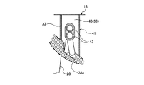
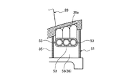
図1は、本実施形態の蒸気タービンにおける静翼ユニットを表す概略図、図2は、静翼ユニットの正面図、図3は、外輪における蒸気入口部の断面図、図4は、図3のIV−IV断面図、図5は、内輪における蒸気入口部の断面図、図6は、図5のVI−VI断面図、図7は、チューブの断面図である。 FIG. 1 is a schematic diagram showing a stationary blade unit in the steam turbine of the present embodiment, FIG. 2 is a front view of the stationary blade unit, FIG. 3 is a cross-sectional view of a steam inlet portion in the outer ring, and FIG. IV-IV sectional view, FIG. 5 is a sectional view of the steam inlet portion in the inner ring, FIG. 6 is a sectional view taken along the line VI-VI in FIG. 5, and FIG. 7 is a sectional view of the tube.
図1及び図2に示すように、最終段における静翼ユニット17は、外輪(分割環)18と内輪(シュラウド)19が周方向に所定間隔で配置される複数の静翼20により連結されて構成されている。外輪18は、リング形状をなし、外周部がケーシング11(図8参照)のフレーム31に固定されることで、断面が筒形状に形成されている。この外輪18は、内部に周方向に沿う隔壁32が固定されることで、第1加熱室(空洞部)33と第1ドレン排出室(ドレン排出部)34が区画形成されている。
As shown in FIGS. 1 and 2, the
一方、内輪19は、外輪18より小径のリング形状をなし、断面が筒形状に形成されている。この内輪19は、内部に周方向に沿う隔壁35が固定されることで、第2加熱室(空洞部)36と第2ドレン排出室(ドレン排出部)37が区画されている。
On the other hand, the
外輪18は、第1加熱室33に蒸気外輪入口部41が設けられると共に、蒸気外輪入口部41に周方向に離間して蒸気外輪出口部42が設けられている。本実施形態では、この蒸気外輪入口部41と蒸気外輪出口部42は、外輪18にほぼ90度離間して設けられることで、それぞれ4個ずつ設けられている。そして、外輪18の第1加熱室33内にて、蒸気外輪入口部41と蒸気外輪出口部42が第1蒸気通路43により連通されている。
The
この第1蒸気通路43は、外輪18の第1加熱室33における内周側に沿って複数(本実施形態では、2個)配置されており、各第1蒸気通路43は、蒸気通路21側の内周面に接触して配置されている。
A plurality (two in this embodiment) of the
具体的に説明すると、図3及び図4に示すように、蒸気外輪入口部41は、第1加熱室33の一部が一対の入口仕切板44,45により区画される外輪入口ヘッダ46として形成されている。そして、蒸気外輪入口部41は、外周側から外輪18を貫通して外輪入口ヘッダ46に連通する蒸気供給口47が設けられると共に、蒸気供給口47から内周側に貫通する蒸気供給口48が設けられている。そして、第1蒸気通路43は、第1加熱室33の内周側に形成された凹部33a内に沿って配置され、端部が入口仕切板45の中央部に貫通して固定されている。なお、複数の第1蒸気通路43は、第1加熱室33の内周側に固定金具49により所定間隔で固定されている。
More specifically, as shown in FIGS. 3 and 4, the steam
また、蒸気外輪出口部42は、図示しないが、蒸気外輪入口部41とほぼ同様の構成となっており、第1加熱室33の一部が一対の出口仕切板により区画される外輪出口ヘッダとして形成され、外部から外輪18を貫通して外輪出口ヘッダに連通する蒸気排出口50(図2参照)が設けられている。そして、第1蒸気通路43は、第1加熱室33の内周側に沿って配置され、端部が出口仕切板の中央部に貫通して固定されている。
Further, although not shown, the steam outer
第1蒸気通路43は、図7に示すように、チューブにより構成されている。即ち、第1蒸気通路43は、中心部に沿って設けられるチューブ本体43aと、このチューブ本体43aの外周部にリング形状をなす複数の襞部43bとから構成されている。複数の襞部43bは、チューブ本体43aの長手方向に所定間隔で設けられ、内部が連通している。
As shown in FIG. 7, the
また、図1及び図2に示すように、内輪19は、第2加熱室36に蒸気内輪入口部51が設けられると共に、蒸気内輪入口部51に周方向に離間して蒸気内輪出口部52が設けられている。本実施形態では、この蒸気内輪入口部51と蒸気内輪出口部52は、内輪19にほぼ90度離間して設けられることで、それぞれ4個ずつ設けられている。そして、蒸気内輪入口部51は、蒸気外輪入口部41と外輪18及び内輪19の径方向に対向して配置され、蒸気内輪出口部52は、蒸気外輪出口部42と外輪18及び内輪19の径方向に対向して配置されている。そして、内輪19の第2加熱室36内にて、蒸気内輪入口部51と蒸気内輪出口部52が第2蒸気通路53により連通されている。
As shown in FIGS. 1 and 2, the
この第2蒸気通路53は、内輪19の第2加熱室36における外周側に沿って複数(本実施形態では、3個)配置されており、各第2蒸気通路53は、蒸気通路21側の外周面に接触して配置されている。
A plurality (three in this embodiment) of the
具体的に説明すると、図5及び図6に示すように、蒸気内輪入口部51は、第2加熱室36の一部が一対の入口仕切板54,55により区画される内輪入口ヘッダ56として形成され、静翼20側から内輪19を貫通して内輪入口ヘッダ56に連通する蒸気供給口57が設けられている。そして、第2蒸気通路53は、第2加熱室36の外周側に形成された凹部36a内に沿って配置され、端部が入口仕切板55の中央部に貫通して固定されている。なお、複数の第2蒸気通路53は、第2加熱室36の外周側に固定金具59により所定間隔で固定されている。
More specifically, as shown in FIGS. 5 and 6, the steam inner
また、蒸気内輪出口部52は、図示しないが、蒸気内輪入口部51とほぼ同様の構成となっており、第2加熱室36の一部が一対の出口仕切板により区画される内輪出口ヘッダとして形成され、静翼20側から内輪19を貫通して内輪出口ヘッダに連通する蒸気排出口が設けられている。そして、第2蒸気通路53は、第2加熱室36の外周側に沿って配置され、端部が出口仕切板の中央部に貫通して固定されている。
Although not shown, the steam inner
なお、第2蒸気通路53は、第1蒸気通路43と同様に、チューブにより構成されており、中心部に沿って設けられるチューブ本体と、このチューブ本体の外周部にリング形状をなす複数の襞部とから構成されている。
The
図2に示すように、複数の静翼20は、ほぼ同様の構成をなし、内部に中空部61が形成されている。この複数の静翼20における所定の中空部61は、蒸気外輪入口部41と蒸気内輪入口部51を連通する入口連通路61aとして機能する。また、複数の静翼20における所定の中空部61は、蒸気外輪出口部42と蒸気内輪出口部52を連通する出口連通路61bとして機能する。
As shown in FIG. 2, the plurality of
なお、図1に示すように、外輪18は、隔壁32により第1加熱室33と第1ドレン排出室34が区画されており、第1ドレン排出室34は、各静翼20の中空部61に連通すると共に、ドレン排出通路71が連通している。また、内輪19は、隔壁35により第2加熱室36と第2ドレン排出室37が区画されており、第2ドレン排出室37は、各静翼20の中空部61に連通すると共に、ドレン排出通路(図示略)が連通している。第1ドレン排出室34及び第2ドレン排出室37は、静翼20に設けられたスリット(図示略)から入ったドレンが溜まる。そして、溜まったドレンはドレン排出通路から排出される。
As shown in FIG. 1, in the
ボイラや蒸気タービンなどから抽気した蒸気は、外輪18における各蒸気供給口47から各蒸気外輪入口部41に供給される。各蒸気外輪入口部41に供給された蒸気は、外輪18の第1加熱室33にある複数の第1蒸気通路43を通って蒸気外輪出口部42に流れ、この蒸気外輪出口部42の蒸気排出口50から外部に排出される。そのため、図1に示すように、蒸気が外輪18の第1加熱室33における内周側に沿った第1蒸気通路43を通ることから、この蒸気により第1加熱室33(第1蒸気通路43)を介して外輪18の内周側が加熱され、各静翼20の外輪側端部が加熱される。
Steam extracted from a boiler, a steam turbine, or the like is supplied to each steam
また、図2に示すように、各蒸気外輪入口部41に供給された蒸気は、対向する静翼20の入口連通路61aを通って内輪19における各蒸気内輪入口部51に供給される。各蒸気内輪入口部51に供給された蒸気は、内輪19の第2加熱室36にある複数の第2蒸気通路53を通って蒸気内輪出口部52に流れる。そして、この蒸気内輪出口部52の蒸気は、対向する静翼20の出口連通路61bを通って外輪18における蒸気外輪出口部42に流れ、この蒸気外輪出口部42の蒸気排出口50から外部に排出される。そのため、図1に示すように、蒸気が内輪19の第2加熱室36における外周側に沿った第2蒸気通路53を通ることから、この蒸気により第2加熱室36(第2蒸気通路53)を介して内輪19の外周側が加熱され、各静翼20の外輪側端部が加熱される。
Further, as shown in FIG. 2, the steam supplied to each steam
蒸気通路21を流れる蒸気は、最終段の静翼20に至ると、湿り蒸気となり、この湿り蒸気に含まれるドレンが最終段の静翼20における外輪18や内輪19に衝突して付着する。特に、静翼20の外輪側端部及び内輪側端部に多くのドレンが付着するが、このとき、外輪18や内輪19、静翼20の外輪側端部及び内輪側端部は、各蒸気通路43,53を通る蒸気により加熱されていることから、付着したドレンは、再び蒸発して蒸気となる。静翼20から飛散したドレンが動翼16に衝突することがなくなり、動翼16でのエロージョンが抑制される。
When the steam flowing through the
このように本実施形態の静翼ユニットにあっては、外輪18と内輪19が周方向に所定間隔で配置される複数の静翼20により連結される静翼ユニット17において、外輪18の第1加熱室33に設けられる蒸気外輪入口部41と、外輪18の第1加熱室33に蒸気外輪入口部41に周方向に離間して設けられる蒸気外輪出口部42と、外輪18の第1加熱室33内で蒸気外輪入口部41と蒸気外輪出口部42とを連通する第1蒸気通路43とを設けている。
As described above, in the stationary blade unit of the present embodiment, in the
従って、蒸気外輪入口部41に供給された蒸気は、外輪18の第1加熱室33内にある第1蒸気通路43を通って蒸気外輪出口部42から排出されるため、蒸気により外輪18を加熱することができ、各静翼20の外輪側端部を加熱することができる。そのため、蒸気通路21を流れる湿り蒸気は、含有するドレンが最終段の外輪18や静翼20の外輪側端部に付着しても、外輪18や静翼20の外輪側端部が加熱されて高温となっていることから、付着したドレンが蒸発して蒸気となり、後段の動翼16でのエロージョンが抑制される。このとき、蒸気は、外輪18の第1加熱室33ではなく第1蒸気通路43を通ることから、少ない蒸気量で必要な個所のみ外輪18や静翼20を加熱することとなり、使用する蒸気量を低減し、少ない蒸気を効率的に使用することで、湿り蒸気によるエロージョンを抑制することができると共に、熱効率の低下を抑制することができる。
Accordingly, the steam supplied to the steam
本実施形態の静翼ユニットでは、第1蒸気通路43を外輪18の第1加熱室33における内周側に沿って配置している。従って、蒸気により外輪18の内周側、つまり、静翼20の外輪側端部を加熱することとなり、蒸気通路21を流れる蒸気に含まれるドレンが多く付着しやすい個所を加熱することとなり、少ない蒸気量で外輪18を適正に加熱することができる。
In the stationary blade unit of the present embodiment, the
本実施形態の静翼ユニットでは、第1蒸気通路43をチューブにより構成している。従って、外輪18の第1加熱室33内に容易に第1蒸気通路43を配置することができ、製造コストを低減することができる。また、この第1蒸気通路43は、中心部に沿って設けられるチューブ本体43aと、このチューブ本体43aの外周部にリング形状をなす複数の襞部43bとから構成されている。従って、第1蒸気通路43の表面積を増加させることで、外輪18を効率良く加熱することができる。
In the stationary blade unit of the present embodiment, the
本実施形態の静翼ユニットでは、蒸気外輪入口部41を、入口仕切板44,45により区画される外輪入口ヘッダ46として構成し、外輪18に外輪入口ヘッダ46に連通する蒸気供給口47を設け、また、蒸気外輪出口部41として、一対の出口仕切板により区画される外輪出口ヘッダとして構成し、外輪18に外輪出口ヘッダに連通する蒸気排出口50を設けている。従って、外部からの蒸気を蒸気外輪入口部41に容易に供給することができると共に、蒸気外輪出口部42から蒸気を容易に排出することができ、また、第1蒸気通路43の端部を容易に蒸気外輪入口部41と蒸気外輪出口部42に連結することができる。
In the stationary blade unit of the present embodiment, the steam
本実施形態の静翼ユニットでは、外輪18の空洞部に第1加熱室33(外輪入口ヘッダ46及び外輪出口ヘッダ)に隣接して第1ドレン排出室34を設け、第1ドレン排出室34を静翼20の中空部61に連通している。従って、静翼20の中空部61で発生したドレン水を第1ドレン排出室34から外部に容易に排出することができる。
In the stationary blade unit of the present embodiment, a first
本実施形態の静翼ユニットでは、内輪19の第2加熱室36に設けられる蒸気内輪入口部51と、第2加熱室36に蒸気内輪入口部51に周方向に離間して設けられる蒸気内輪出口部52と、静翼20内に設けられて前記蒸気外輪入口部41と蒸気内輪入口部51を連通する入口連通路61aと、静翼20内に設けられて蒸気外輪出口部42と蒸気内輪出口52部を連通する出口連通路61bと、第2加熱室36内で蒸気内輪入口部51と蒸気内輪出口部52とを連通する第2蒸気通路53とを設けている。
In the stationary blade unit of this embodiment, the steam
従って、蒸気外輪入口部41に供給された蒸気は、入口連通路61aから蒸気内輪入口部51に流れ、内輪19の第2加熱室36内にある第2蒸気通路53を通って蒸気内輪出口部52に流れ、出口連通路61bを介して蒸気外輪出口部42から排出されるため、蒸気により内輪19を加熱することができ、各静翼20の内輪側端部を加熱することができる。そのため、蒸気通路21を流れる湿り蒸気は、含有するドレンが最終段の内輪19や静翼20の内輪側端部に付着しても、内輪19や静翼20の内輪側端部が加熱されて高温となっていることから、付着したドレンが蒸発して蒸気となり、後段の動翼16でのエロージョンが抑制される。このとき、蒸気は、内輪19の第2加熱室36ではなく第2蒸気通路53を通ることから、少ない蒸気量で必要な個所のみ内輪19や静翼20を加熱することとなり、使用する蒸気量を低減し、少ない蒸気を効率的に使用することで、湿り蒸気によるエロージョンを抑制することができると共に、熱効率の低下を抑制することができる。
Therefore, the steam supplied to the steam outer
本実施形態の静翼ユニットでは、第2蒸気通路53を内輪19の第2加熱室36における外周側に沿って配置している。従って、蒸気により内輪19の外周側、つまり、静翼20の内輪側端部を加熱することとなり、蒸気通路21を流れる蒸気に含まれるドレンが多く付着しやすい個所を加熱することとなり、少ない蒸気量で外輪18を適正に加熱することができる。
In the stationary blade unit of the present embodiment, the
本実施形態の静翼ユニットでは、第2蒸気通路53をチューブにより構成している。従って、内輪19の第2加熱室36内に容易に第2蒸気通路53を配置することができ、製造コストを低減することができる。また、この第2蒸気通路53は、中心部に沿って設けられるチューブ本体と、このチューブ本体の外周部にリング形状をなす複数の襞部とから構成されている。従って、第2蒸気通路53の表面積を増加させることで、内輪19を効率良く加熱することができる。
In the stationary blade unit of the present embodiment, the
また、本実施形態の蒸気タービンにあっては、ケーシング11と、ケーシング11内に回転自在に支持されたロータ12と、動翼16の基端部がロータ12に支持されてロータ12の周方向に所定間隔で複数配置される複数段の動翼ユニット14と、静翼20の基端部と先端部がケーシング11に支持されてロータ12の周方向に所定間隔で複数配置される複数段の静翼ユニット17とを設け、複数段の静翼ユニット17のうちの最終段の静翼ユニット17として上述した静翼ユニットを適用している。
Further, in the steam turbine of the present embodiment, the
従って、蒸気により外輪18や内輪19、静翼20の外輪側端部や内輪側端部を加熱することから、蒸気通路21を流れる湿り蒸気は、含有するドレンが最終段の外輪18や内輪19、静翼20の外輪側端部や内輪側端部に付着しても、付着したドレンが蒸発して蒸気となり、後段の動翼16でのエロージョンが抑制される。このとき、蒸気は、外輪18の第1加熱室33ではなく第1蒸気通路43を通ることから、少ない蒸気量で必要な個所のみ外輪18や内輪19及び静翼20を加熱することとなり、使用する蒸気量を低減し、少ない蒸気を効率的に使用することで、湿り蒸気によるエロージョンを抑制することができると共に、熱効率の低下を抑制することができる。
Therefore, the
なお、上述した実施形態にて、蒸気外輪入口部41及び蒸気外輪出口部42と、蒸気内輪入口部51及び蒸気内輪出口部52を4組設け、一部(8個)の静翼20内に蒸気を流したが、この構成に限定されるものではない。例えば、蒸気外輪入口部41及び蒸気外輪出口部42と、蒸気内輪入口部51及び蒸気内輪出口部52を2組設け、4個の静翼20内に蒸気を流したり、蒸気外輪入口部41及び蒸気外輪出口部42と、蒸気内輪入口部51及び蒸気内輪出口部52を8組設け、16個の静翼20内に蒸気を流したりしてもよく、更に、全ての静翼20内に蒸気を流したりしてもよい。
In the above-described embodiment, four sets of the steam outer
また、上述した実施形態では、各加熱室33,36内に配置する蒸気通路43,53をチューブとしたが、この構成に限定されるものではない。例えば、各加熱室33,36内に形成された凹部33a,36aを板部材により被覆することで、蒸気通路を形成してもよく、各加熱室33,36内の一部の空間を区画して蒸気通路を形成してもよい。また、蒸気通路43,53をチューブとして複数設けたが、その数に限定されるものではない。
In the above-described embodiment, the
また、上述した実施形態では、蒸気外輪入口部41及び蒸気外輪出口部42と、蒸気内輪入口部51及び蒸気内輪出口部52として、外輪入口ヘッダ46及び外輪出口ヘッダと、内輪入口ヘッダ56及び内輪出口ヘッダを設けたが、蒸気通路43,53としてのチューブを外輪18の外部まで延出してもよい。
In the embodiment described above, the steam
また、上述した実施形態では、本発明の静翼ユニットを蒸気タービンの最終段の静翼ユニットに適用したが、その他の静翼ユニットに適用してもよい。 In the embodiment described above, the stationary blade unit of the present invention is applied to the stationary blade unit at the final stage of the steam turbine, but may be applied to other stationary blade units.
11 ケーシング
12 ロータ
13 軸受
14 動翼ユニット
15 ロータディスク
16 動翼
17 静翼ユニット
18 外輪
19 内輪
20 静翼
21 蒸気通路
33 第1加熱室(空洞部)
34 第1ドレン排出室(ドレン排出部)
36 第2加熱室(空洞部)
37 第2ドレン排出室(ドレン排出部)
41 蒸気外輪入口部
42 蒸気外輪出口部
43 第1蒸気通路
44,45 入口仕切板
46 外輪入口ヘッダ
47 蒸気供給口
48 蒸気供給口
49 固定金具
50 蒸気排出口
51 蒸気内輪入口部
52 蒸気内輪出口部
53 第2蒸気通路
54,55 入口仕切板
56 内輪入口ヘッダ
57 蒸気供給口
59 固定金具
61 中空部
61a 入口連通路
61b 出口連通路
71 ドレン排出通路
DESCRIPTION OF
34 First drain discharge chamber (drain discharge section)
36 Second heating chamber (cavity)
37 Second drain discharge chamber (drain discharge section)
41 Steam
Claims (8)
前記外輪の空洞部に設けられる蒸気外輪入口部と、
前記外輪の空洞部に前記蒸気外輪入口部に周方向に離間して設けられる蒸気外輪出口部と、
前記外輪の空洞部内で前記蒸気外輪入口部と前記蒸気外輪出口部とを連通する第1蒸気通路と、
を有し、
前記第1蒸気通路は、前記外輪の空洞部における内周側に沿って前記空洞部の一部を区画して配置される、
ことを特徴とする静翼ユニット。 In a stationary blade unit in which an outer ring and an inner ring are connected by a plurality of stationary blades arranged at predetermined intervals in the circumferential direction,
A steam outer ring inlet provided in a cavity of the outer ring;
A steam outer ring outlet portion provided in the outer ring cavity in a circumferentially spaced manner at the steam outer ring inlet portion;
A first steam passage communicating the steam outer ring inlet part and the steam outer ring outlet part in the cavity of the outer ring;
Have
The first steam passage is arranged by dividing a part of the cavity along the inner peripheral side of the cavity of the outer ring.
A stationary blade unit characterized by that.
前記ケーシング内に回転自在に支持されたロータと、
動翼の基端部が前記ロータに支持されて前記ロータの周方向に所定間隔で複数配置される複数段の動翼ユニットと、
静翼の基端部と先端部が前記ケーシングに支持されて前記ロータの周方向に所定間隔で複数配置される複数段の静翼ユニットと、
を有し、
前記複数段の静翼ユニットのうちの最終段の静翼ユニットとして請求項1から請求項7のいずれか一項に記載の静翼ユニットが適用される、
ことを特徴とする蒸気タービン。
A casing,
A rotor rotatably supported in the casing;
A plurality of rotor blade units in which a base end portion of a rotor blade is supported by the rotor and is arranged in a plurality at predetermined intervals in the circumferential direction of the rotor;
A plurality of stages of stationary blade units in which a base end portion and a distal end portion of a stationary blade are supported by the casing and are arranged at a predetermined interval in the circumferential direction of the rotor;
Have
The stator blade unit according to any one of claims 1 to 7 is applied as a stator blade unit of the last stage among the plurality of stator blade units.
A steam turbine characterized by that.
Priority Applications (6)
| Application Number | Priority Date | Filing Date | Title |
|---|---|---|---|
| JP2014133260A JP6284447B2 (en) | 2014-06-27 | 2014-06-27 | Stator blade unit and steam turbine |
| KR1020167035587A KR101867750B1 (en) | 2014-06-27 | 2015-06-09 | Vane unit and steam turbine |
| PCT/JP2015/066617 WO2015198853A1 (en) | 2014-06-27 | 2015-06-09 | Stator vane unit and steam turbine |
| DE112015002981.8T DE112015002981B4 (en) | 2014-06-27 | 2015-06-09 | Blade unit and steam turbine |
| CN201580033732.3A CN106661951B (en) | 2014-06-27 | 2015-06-09 | Stator blade blade unit and steam turbine |
| US15/318,782 US10267150B2 (en) | 2014-06-27 | 2015-06-09 | Vane unit and steam turbine |
Applications Claiming Priority (1)
| Application Number | Priority Date | Filing Date | Title |
|---|---|---|---|
| JP2014133260A JP6284447B2 (en) | 2014-06-27 | 2014-06-27 | Stator blade unit and steam turbine |
Publications (3)
| Publication Number | Publication Date |
|---|---|
| JP2016011626A JP2016011626A (en) | 2016-01-21 |
| JP2016011626A5 JP2016011626A5 (en) | 2017-04-06 |
| JP6284447B2 true JP6284447B2 (en) | 2018-02-28 |
Family
ID=54937946
Family Applications (1)
| Application Number | Title | Priority Date | Filing Date |
|---|---|---|---|
| JP2014133260A Expired - Fee Related JP6284447B2 (en) | 2014-06-27 | 2014-06-27 | Stator blade unit and steam turbine |
Country Status (6)
| Country | Link |
|---|---|
| US (1) | US10267150B2 (en) |
| JP (1) | JP6284447B2 (en) |
| KR (1) | KR101867750B1 (en) |
| CN (1) | CN106661951B (en) |
| DE (1) | DE112015002981B4 (en) |
| WO (1) | WO2015198853A1 (en) |
Families Citing this family (4)
| Publication number | Priority date | Publication date | Assignee | Title |
|---|---|---|---|---|
| CN107023317A (en) * | 2017-05-25 | 2017-08-08 | 华能国际电力股份有限公司 | A kind of reheat-type multistage axial turbine and its method of work |
| WO2019130517A1 (en) * | 2017-12-27 | 2019-07-04 | 川崎重工業株式会社 | Steam turbine |
| CN110030039A (en) * | 2019-05-16 | 2019-07-19 | 哈尔滨汽轮机厂有限责任公司 | A kind of steam turbine dehumidifying grade hollow shelf |
| JP7293011B2 (en) | 2019-07-10 | 2023-06-19 | 三菱重工業株式会社 | Steam turbine stator vane, steam turbine, and method for heating steam turbine stator vane |
Family Cites Families (17)
| Publication number | Priority date | Publication date | Assignee | Title |
|---|---|---|---|---|
| JPS5573501U (en) * | 1978-11-15 | 1980-05-21 | ||
| JPS5573501A (en) | 1978-11-29 | 1980-06-03 | Kobayashi Kikai Kogyo Kk | Molding press device of plywood*etc* |
| US4721433A (en) * | 1985-12-19 | 1988-01-26 | United Technologies Corporation | Coolable stator structure for a gas turbine engine |
| JPH01300002A (en) * | 1988-05-24 | 1989-12-04 | Toshiba Corp | Steam turbine nozzle device |
| JPH0326802A (en) * | 1989-06-23 | 1991-02-05 | Hitachi Ltd | Stationary blade apparatus of steam turbine |
| JP2723334B2 (en) * | 1990-04-12 | 1998-03-09 | 株式会社東芝 | Steam turbine nozzle water droplet removal equipment |
| US5634766A (en) * | 1994-08-23 | 1997-06-03 | General Electric Co. | Turbine stator vane segments having combined air and steam cooling circuits |
| JP3630740B2 (en) * | 1994-12-08 | 2005-03-23 | 株式会社東芝 | Drain discharge device for steam turbine |
| JP3617212B2 (en) | 1996-10-01 | 2005-02-02 | 富士電機システムズ株式会社 | Steam turbine stationary blade heating method |
| DE19715966A1 (en) * | 1997-04-17 | 1998-10-29 | Carsten Binder | Guide vane for steam turbines |
| JP2002309906A (en) * | 2001-04-11 | 2002-10-23 | Mitsubishi Heavy Ind Ltd | Steam cooling type gas turbine |
| JP5558120B2 (en) * | 2010-01-12 | 2014-07-23 | 株式会社東芝 | Steam turbine rotor cooling device and steam turbine provided with this cooling device |
| JP5449128B2 (en) | 2010-12-28 | 2014-03-19 | 三菱重工業株式会社 | Condensed steam turbine and its modification method |
| JP2013148039A (en) * | 2012-01-20 | 2013-08-01 | Toshiba Corp | Steam turbine |
| JP5868802B2 (en) * | 2012-07-20 | 2016-02-24 | 株式会社東芝 | Turbine |
| JP5865798B2 (en) * | 2012-07-20 | 2016-02-17 | 株式会社東芝 | Turbine sealing device and thermal power generation system |
| JP5865204B2 (en) * | 2012-07-20 | 2016-02-17 | 株式会社東芝 | Axial turbine and power plant |
-
2014
- 2014-06-27 JP JP2014133260A patent/JP6284447B2/en not_active Expired - Fee Related
-
2015
- 2015-06-09 DE DE112015002981.8T patent/DE112015002981B4/en not_active Expired - Fee Related
- 2015-06-09 US US15/318,782 patent/US10267150B2/en not_active Expired - Fee Related
- 2015-06-09 WO PCT/JP2015/066617 patent/WO2015198853A1/en active Application Filing
- 2015-06-09 CN CN201580033732.3A patent/CN106661951B/en not_active Expired - Fee Related
- 2015-06-09 KR KR1020167035587A patent/KR101867750B1/en active IP Right Grant
Also Published As
| Publication number | Publication date |
|---|---|
| US20170130584A1 (en) | 2017-05-11 |
| DE112015002981B4 (en) | 2020-12-03 |
| KR101867750B1 (en) | 2018-06-15 |
| DE112015002981T5 (en) | 2017-03-09 |
| KR20170007456A (en) | 2017-01-18 |
| CN106661951A (en) | 2017-05-10 |
| WO2015198853A1 (en) | 2015-12-30 |
| JP2016011626A (en) | 2016-01-21 |
| US10267150B2 (en) | 2019-04-23 |
| CN106661951B (en) | 2018-07-10 |
Similar Documents
| Publication | Publication Date | Title |
|---|---|---|
| JP6284447B2 (en) | Stator blade unit and steam turbine | |
| US20130164119A1 (en) | Seal structure and centrifugal compressor | |
| JP6110035B2 (en) | Rotor of thermal turbomachine | |
| US20140356143A1 (en) | Assembly for a fluid flow machine | |
| CN101825001B (en) | Axial-flow turbine | |
| JP2020002937A (en) | Stator vane segment, and steam turbine | |
| RU2655068C1 (en) | Steam turbine and method for operation of steam turbine | |
| JP2016011626A5 (en) | ||
| CN110114555B (en) | Steam turbine | |
| JP5693112B2 (en) | Axial turbine and method for exhausting flow from an axial turbine | |
| JP6878046B2 (en) | Steam turbine system | |
| JP2011137413A (en) | Steam turbine | |
| JP2018168844A (en) | Drain removal device and steam turbine | |
| JP6813446B2 (en) | Drain discharge structure of steam turbine and its modification method | |
| US10626726B2 (en) | Tubular adhesion turbine or pump | |
| JP6871009B2 (en) | Steam turbine | |
| JP6257946B2 (en) | Geothermal turbine | |
| JP2018135837A (en) | Steam turbine plant | |
| JP6826449B2 (en) | Steam turbine system | |
| JP6700893B2 (en) | Impeller, rotating machine | |
| WO2019130517A1 (en) | Steam turbine | |
| JP2017025879A (en) | Rotor blade and rotary machine | |
| PL68461Y1 (en) | Steam microturbine |
Legal Events
| Date | Code | Title | Description |
|---|---|---|---|
| A521 | Written amendment |
Free format text: JAPANESE INTERMEDIATE CODE: A523 Effective date: 20170227 |
|
| A621 | Written request for application examination |
Free format text: JAPANESE INTERMEDIATE CODE: A621 Effective date: 20170227 |
|
| A131 | Notification of reasons for refusal |
Free format text: JAPANESE INTERMEDIATE CODE: A131 Effective date: 20171107 |
|
| A521 | Written amendment |
Free format text: JAPANESE INTERMEDIATE CODE: A523 Effective date: 20171215 |
|
| TRDD | Decision of grant or rejection written | ||
| A01 | Written decision to grant a patent or to grant a registration (utility model) |
Free format text: JAPANESE INTERMEDIATE CODE: A01 Effective date: 20180109 |
|
| A61 | First payment of annual fees (during grant procedure) |
Free format text: JAPANESE INTERMEDIATE CODE: A61 Effective date: 20180130 |
|
| R150 | Certificate of patent or registration of utility model |
Ref document number: 6284447 Country of ref document: JP Free format text: JAPANESE INTERMEDIATE CODE: R150 |
|
| S533 | Written request for registration of change of name |
Free format text: JAPANESE INTERMEDIATE CODE: R313533 |
|
| R350 | Written notification of registration of transfer |
Free format text: JAPANESE INTERMEDIATE CODE: R350 |
|
| LAPS | Cancellation because of no payment of annual fees |