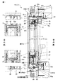
以下に、添付図面を参照して本発明の実施の形態を詳細に説明する。図1及び図2に示すように、本実施の形態に係るサッシ1は、アルミ樹脂複合障子のすべり出しサッシであり、障子3はアルミニウム製形材の上框5、下框7及び左右の竪框9、9をガラス4の四周に框組してあり、各框の室内側には樹脂製形材6が取付けてある。枠11はアルミニウム製の上枠13、下枠15及び左右の竪枠17、17を枠組してあり、室内側には樹脂製形材18が取付けてある。
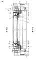
図2に示すように、左竪框9と左竪枠17との間及び右竪框9と左竪枠17との間には各々障子3を室外側に吊り出すステー(支持具)19が設けてある。
図1に示すように、障子3の下框7の上部には、ガラス4の下端部を保持するガラス保持溝21が設けてあり、ガラス保持溝21の下方には中空部23が形成されている。ガラス保持溝21にはガラス4の下端部を覆うスチール製のガラス間口補強材25が配置されており、中空部23には、スチール製の下框補強材27が設けてあり、ガラス間口補強材25は、下框補強材27にねじ28で固定してある。ガラス間口補強材25の上面には、ガラス下端面に対向する第1熱膨張耐火材32aがガラス間口補強材25の長手方向に全体に亘って設けてある。ガラス間口補強材25は下框7の左右端部を除いてガラス保持溝21内に載置されており、下框7のガラス保持溝21の溝底において、ガラス間口補強材25がない左右端部には各々排水穴が形成されている。下框補強材27の左右端部において、下框7の排水穴が対向する位置に第2熱膨張耐火材32bが配置されている。
下框7の下面には、スチール製の下補助板29がねじ30で固定してある。下補助板29は下框7に取付けてある樹脂製形材6の長手方向に亘って樹脂製形材6の下面を覆っている。
Embodiments of the present invention will be described below in detail with reference to the accompanying drawings. As shown in FIGS. 1 and 2, the sash 1 according to the present embodiment is a sliding sash of an aluminum resin composite shoji, and the shoji 3 is composed of an upper shape 5, a lower shape 7, and left and right shapes of an aluminum shape material. 9 and 9 are braided around the circumference of the glass 4, and a resin shape 6 is attached to the indoor side of each trough. The frame 11 includes an aluminum upper frame 13, a lower frame 15, and left and right eaves frames 17, 17. A resin shape 18 is attached to the indoor side.
As shown in FIG. 2, stays (supports) 19 for hanging the shoji 3 to the outdoor side are respectively provided between the port 9 and the port frame 17 and between the starboard 9 and the port frame 17. It is provided.
As shown in FIG. 1, a glass holding groove 21 that holds the lower end portion of the glass 4 is provided in the upper part of the lower arm 7 of the shoji 3, and a hollow portion 23 is formed below the glass holding groove 21. Yes. The glass holding groove 21 is provided with a steel glass front reinforcing material 25 covering the lower end of the glass 4, and the hollow portion 23 is provided with a steel lower edge reinforcing material 27, and the glass front reinforcing material is provided. 25 is fixed to the lower brace reinforcement 27 with screws 28. A first thermal expansion refractory material 32 a facing the lower end surface of the glass is provided on the entire upper surface of the glass front reinforcing member 25 in the longitudinal direction of the glass front reinforcing member 25. The glass front reinforcing member 25 is placed in the glass holding groove 21 except for the left and right end portions of the lower rib 7, and the left and right ends where the glass front reinforcing member 25 is not provided at the bottom of the glass holding groove 21 of the lower rib 7. Each part is formed with a drain hole. The second thermal expansion refractory material 32b is disposed at the left and right end portions of the lower heel reinforcement 27 at positions where the drain holes of the lower heel 7 face each other.
A steel lower auxiliary plate 29 is fixed to the lower surface of the lower rod 7 with screws 30. The lower auxiliary plate 29 covers the lower surface of the resin shaped member 6 over the longitudinal direction of the resin shaped member 6 attached to the lower collar 7.
上框5の下部にもガラス保持溝21が設けてあり、ガラス保持溝21の上部には中空部23が形成されている。上框5のガラス保持溝21にはガラス4の上端部を覆うスチール製のガラス間口補強材25が配置されており、ガラス間口補強材25は上框5にねじ26で固定してある。ガラス間口補強材25の下面にはガラス上端面に対向する第1熱膨張耐火材32aがガラス間口補強材25の長手方向に全体に亘って設けてある。
上框5の上面には、スチール製の上補助板31がねじ34により上框5に固定してある。上補助板31は、上框5に取付けてある樹脂製形材6の長手方向に亘って樹脂製形材6の上面を覆っているが、下記する反り防止金具33が設けてある位置は除いてある。
上框5に取付けてある樹脂製形材6には、中空部6aが形成してあり、この中空部6a内には、スチール製の反り防止金具33が設けてある。
反り防止金具33は、図3に示すように、台座34と、係止部材35と、スプリング37とを備えており、係止部材35の基端部35aを台座34に回動自在に軸支してあり、スプリング37により、係止部材35の先端部35bが上方に向けて回動するように付勢している。
A glass holding groove 21 is also provided in the lower part of the upper collar 5, and a hollow part 23 is formed in the upper part of the glass holding groove 21. A glass front opening reinforcing material 25 made of steel that covers the upper end portion of the glass 4 is disposed in the glass holding groove 21 of the upper side 5. The glass front opening reinforcing material 25 is fixed to the upper side 5 with a screw 26. A first thermal expansion refractory material 32 a facing the upper end surface of the glass is provided on the entire lower surface of the glass front reinforcing member 25 in the longitudinal direction of the glass front reinforcing member 25.
On the upper surface of the upper collar 5, a steel upper auxiliary plate 31 is fixed to the upper collar 5 with screws 34. The upper auxiliary plate 31 covers the upper surface of the resin shaped member 6 over the longitudinal direction of the resin shaped member 6 attached to the upper collar 5, except for the position where the warp preventing metal fitting 33 described below is provided. It is.
A hollow portion 6a is formed in the resin shape member 6 attached to the upper collar 5, and a steel warp preventing metal fitting 33 is provided in the hollow portion 6a.
As shown in FIG. 3, the warp preventing metal fitting 33 includes a pedestal 34, a locking member 35, and a spring 37, and a base end portion 35 a of the locking member 35 is pivotally supported by the pedestal 34. The tip 37b of the locking member 35 is biased by the spring 37 so as to rotate upward.
図2に示すように、左右の竪框9、9には、各々ガラス保持溝21に上述したスチール製のガラス間口補強材25が設けてあり、中空部9aにはスチール製の竪框補強材39が設けてあり、ガラス間口補強材39と竪框補強材39とはねじ40により固定されている。ガラス間口補強材25には、左右のガラス端面に対向する第1熱膨張耐火材32aがガラス間口補強材25の長手方向に全体に亘って設けてある。
また、各竪框9のガラス保持溝21の室内側壁には、その室外側面にガラス間口補強材25に対向する第12熱膨張耐火材32mが設けてある。
As shown in FIG. 2, the left and right ridges 9, 9 are each provided with the above-mentioned steel glass front reinforcement member 25 in the glass holding groove 21, and the hollow portion 9a has a steel ridge reinforcement member. 39 is provided, and the glass front reinforcement 39 and the heel reinforcement 39 are fixed by screws 40. The glass front reinforcing material 25 is provided with a first thermal expansion refractory material 32 a facing the left and right glass end faces over the entire length of the glass front reinforcing material 25.
Moreover, the 12th thermal expansion refractory material 32m which opposes the glass front opening reinforcement 25 is provided in the indoor side wall of the glass holding groove 21 of each cage | basket 9 in the outdoor side surface.
図1及び図4に示すように、上枠13には反り防止金具33を受ける反り防止金具受け41固定してあり、反り防止金具受け41の受け金41aが下方に向けて突設してある。また、図1に示すように、上枠13には、第3熱膨張耐火材32cを保持する熱膨張耐火材保持具43が上枠13の見込方向略中央でねじ固定されている。熱膨張耐火材保持具43には室内側に延出する保持部43aが形成してあり、保持部43aは上框5の室内側見付面と見込面とのコーナ部5cに近接するように傾斜している。熱膨張耐火材保持具43の保持部43aに第3熱膨張耐火材32cが設けてあり、第3熱膨張耐火材32cは面を室外側に向けて室内側端を内周側に向けて傾斜しており且つ上補助板31の上面に対向していると共に、上框5の室内側見付面と見込面とのコーナ部5cに室内側で対向している。
下枠15には、第4熱膨張耐火材32dを保持する熱膨張耐火材保持具43が下枠15の見込方向略中央でねじ固定されている。熱膨張耐火材保持具43は室内側で枠内周側に延出する保持部43aが形成してあり、保持部43aは下框7の室内側見付面と見込面とのコーナ部7cに近接するように傾斜している。下枠15の第4熱膨張耐火材32dは面を室外側に向けて室内側端を内周側に向けて傾斜しており且つ下補助板29の下面に対向して設けてあると共に、下框7の室内側見付面と見込面とのコーナ部7cに室内側で対向している。
下枠15には、室外側壁の長手方向一端部側に排水穴42が設けてあり、この排水穴42に対応する位置に断面略L字形状を成す熱膨張耐火材保持具44が設けてあり、排水穴42に対向する位置に第5熱膨張耐火材32eが設けてある。
As shown in FIGS. 1 and 4, the upper frame 13 is fixed with a warp prevention bracket receiver 41 that receives the warp prevention bracket 33, and a receiving metal 41 a of the warp prevention bracket receiver 41 projects downward. . As shown in FIG. 1, a thermal expansion refractory material holder 43 that holds the third thermal expansion refractory material 32 c is screwed to the upper frame 13 at the approximate center of the upper frame 13 in the expected direction. The thermal expansion refractory holder 43 is formed with a holding portion 43a extending to the indoor side, and the holding portion 43a is close to the corner portion 5c between the indoor-side finding surface and the expected surface of the upper collar 5. Inclined. A third thermal expansion refractory material 32c is provided in the holding portion 43a of the thermal expansion refractory material holder 43, and the third thermal expansion refractory material 32c is inclined with the surface facing the outdoor side and the indoor side end facing the inner peripheral side. And is opposed to the upper surface of the upper auxiliary plate 31, and is opposed to the corner portion 5c of the indoor side finding surface and the expected surface of the upper collar 5 on the indoor side.
A thermal expansion refractory material holder 43 that holds the fourth thermal expansion refractory material 32 d is screwed to the lower frame 15 at the approximate center of the lower frame 15 in the expected direction. The thermal expansion refractory holder 43 is formed with a holding portion 43a extending to the inner peripheral side of the frame on the indoor side, and the holding portion 43a is formed on a corner portion 7c between the indoor-side finding surface and the expected surface of the lower rod 7. It is inclined to be close. The fourth thermal expansion refractory material 32d of the lower frame 15 is inclined with the surface facing the outdoor side and the indoor side end facing the inner peripheral side, and is opposed to the lower surface of the lower auxiliary plate 29. It faces the corner portion 7c between the indoor-side finding surface and the expected surface of the bowl 7 on the indoor side.
The lower frame 15 is provided with a drain hole 42 at one end side in the longitudinal direction of the outdoor wall, and a thermal expansion refractory material holder 44 having a substantially L-shaped cross section is provided at a position corresponding to the drain hole 42. A fifth thermal expansion refractory material 32e is provided at a position facing the drain hole 42.
図2に示すように、左右の竪枠17、17には、各々は、下端部の見込面に熱膨張耐火材保持具45がねじで固定してあり、竪框9の見込面に対向する位置に第6熱膨張耐火材32fが設けてある。第6熱膨張耐火材32fは、熱膨張耐火材保持具45に嵌合してあり、経年劣化による剥がれ落ちるのを防止している。
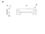
障子3において、ガラス4の各コーナ部には、図5に示すコーナ金具47が設けてある。コーナ金具47のガラス4側面には、図1及び図2に示すように、第13熱膨張耐火材32nが設けてある。
尚、上述した第1熱膨張耐火材32a及び下述する第12熱膨張耐火材32m、第13熱膨張耐火材32nには熱が伝わり難い箇所に設けてあるので低温熱発泡体(約160℃で発泡を開始する)が用いられており、その他の熱膨張耐火材、即ち第2熱膨張耐火材32b〜第11熱膨張耐火材32kには、一般的は熱発泡体(約200℃で発泡を開始する)が用いられている。
As shown in FIG. 2, each of the left and right saddle frames 17, 17 has a thermal expansion refractory material holder 45 fixed to the prospective surface of the lower end with a screw, and faces the prospective surface of the saddle 9. A sixth thermal expansion refractory material 32f is provided at the position. The sixth thermal expansion refractory material 32f is fitted in the thermal expansion refractory material holder 45, and prevents it from peeling off due to deterioration over time.
In the shoji 3, each corner portion of the glass 4 is provided with a corner fitting 47 shown in FIG. As shown in FIGS. 1 and 2, a thirteenth thermal expansion refractory material 32 n is provided on the side surface of the glass 4 of the corner fitting 47.
The first thermal expansion refractory material 32a and the twelfth thermal expansion refractory material 32m and the thirteenth thermal expansion refractory material 32n described above are provided at locations where heat is not easily transmitted. In other thermal expansion refractory materials, that is, the second thermal expansion refractory material 32b to the eleventh thermal expansion refractory material 32k, generally, a thermal foam (foamed at about 200 ° C.) is used. Is used).
次に、本実施の形態にかかるサッシ1の作用効果について説明する。
図1に示すように、火災時に、アルミ樹脂複合障子3の樹脂形材6が焼け落ちた場合でも、火災の熱により下枠15に設けた第4熱膨張耐火材32dが膨張して下框7の下補助板29に当接して、下框7と下枠15との間の空間を塞ぐ。これにより、火災時にアルミ樹脂複合障子3の下框7と下枠15との間から外気が室内に入り込んだり、室内の炎を外に噴出するのを防止できる。
障子の上框5と上枠13との間では、第3熱膨張耐火材32cが膨張して上補助板31に当接して、上框5と上枠13との間の空間を塞ぐ。したがって、上框5と上枠13との間においても、火災時にこれらの間から外気が室内に入り込んだり、室内の炎を外に噴出するのを防止できる。
上枠13に設けた第3熱膨張耐火材32c及び下枠15に設けた第4熱膨張耐火材32dは、室内側において各々障子3の見込面と室内側見付面とのコーナ部5c、7cに対向して設けてあると共に火災の熱により膨張して室内側からコーナ部5c、7cに当接する。これらの熱膨張耐火材32c、32dは、火災の熱により膨張して室内側からコーナ部5c、7cに当接する位置にあるから、障子との距離が最も近い位置に配置でき、火災時に膨張したときに上枠13及び下枠15と、障子3との間を確実に且つ容易に塞ぐことができる。
即ち、上枠13には、対向する上框5の室内側見付面と見込面とのコーナ部5cに室内側から当接する第3熱膨張耐火材32cを設けているので、上框5の見込み面と上枠13の見込み面との間隔に比較して第3熱膨張耐火材32cと上框5との距離を短くできるから、上枠13にのみ熱膨張耐火材32cを設けるだけで隙間を塞ぐことができ、従来技術のように枠と框との両方に熱膨張耐火材を設ける必要がないので、熱膨張耐火材の使用量を少なくできると共に一方にのみ熱膨張耐火材を設けるだけなので施工が容易である。下枠15と下框7においてもコーナ部7cに室内側から当接する第4熱膨張耐火材32dを設けているので、上枠13と上框5の場合と同様に熱膨張耐火材の使用量を少なくできると共に施工が容易である。
また、第3熱膨張耐火材32c及び第4熱膨張耐火材32dは、面を室外側に向けて傾斜しているから、室外側の熱を面全体で受け易く、火災発生時に面全体が早期に膨張して枠と障子との間を塞ぐことができる。
更に、上枠13に第3熱膨張耐火材32cを保持する熱膨張耐火材保持具43を設けて、熱膨張耐火材保持具43は上枠の見込み面にねじで固定してあるから、上框5のコーナ部5cに対向する位置に面を室外側に向けて且つ室内側端を内周側に向けて傾斜した第3熱膨張耐火材32cを配置することが、簡易な構成で容易にできる。下枠15においても、第4熱膨張耐火材32dを保持する熱膨張耐火材保持具43を設けているので、上框5のコーナ部5cに対向する位置に面を室外側に向けて室内側端を内周側に向けて傾斜した第4熱膨張耐火材32dを配置することが、簡易な構成で容易にできる。
Next, the effect of the sash 1 concerning this Embodiment is demonstrated.
As shown in FIG. 1, even when the resin shape 6 of the aluminum resin composite shoji 3 is burned off in the event of a fire, the fourth thermal expansion refractory material 32d provided on the lower frame 15 expands due to the heat of the fire. 7 is brought into contact with the lower auxiliary plate 29 to close the space between the lower rod 7 and the lower frame 15. Thereby, it is possible to prevent the outside air from entering the room from between the lower arm 7 and the lower frame 15 of the aluminum resin composite shoji 3 at the time of a fire, and blowing out the flame in the room to the outside.
Between the upper lid 5 and the upper frame 13 of the shoji, the third thermal expansion refractory material 32c expands and comes into contact with the upper auxiliary plate 31 to block the space between the upper fence 5 and the upper frame 13. Therefore, it is possible to prevent the outside air from entering between the insides of the upper cage 5 and the upper frame 13 from being blown into the room or blowing out the flames inside the room during a fire.
The third thermal expansion refractory material 32c provided on the upper frame 13 and the fourth thermal expansion refractory material 32d provided on the lower frame 15 are each a corner portion 5c of the prospective surface of the shoji 3 and the indoor side finding surface on the indoor side, It is provided opposite to 7c and expands due to the heat of the fire and comes into contact with the corner portions 5c and 7c from the indoor side. Since these thermal expansion refractory materials 32c and 32d are in a position where they are expanded by the heat of the fire and come into contact with the corner portions 5c and 7c from the indoor side, they can be arranged at a position closest to the shoji and expanded in the event of a fire. Sometimes the upper frame 13 and the lower frame 15 and the shoji 3 can be reliably and easily closed.
That is, since the upper frame 13 is provided with the third thermal expansion refractory material 32c that comes into contact with the corner portion 5c between the indoor side finding surface and the expected surface of the upper upper plate 5 facing from the indoor side, Since the distance between the third thermal expansion refractory material 32c and the upper rod 5 can be shortened compared to the distance between the prospective surface and the prospective surface of the upper frame 13, a gap can be obtained only by providing the thermal expansion refractory material 32c only on the upper frame 13. Since it is not necessary to provide a thermal expansion refractory material on both the frame and the ridge as in the prior art, the amount of the thermal expansion refractory material can be reduced and only the thermal expansion refractory material is provided on one side. So construction is easy. Since the lower frame 15 and the lower rod 7 are also provided with the fourth thermal expansion refractory material 32d that comes into contact with the corner portion 7c from the indoor side, the usage amount of the thermal expansion refractory material as in the case of the upper frame 13 and the upper rod 5 Can be reduced and construction is easy.
Moreover, since the 3rd thermal expansion refractory material 32c and the 4th thermal expansion refractory material 32d incline the surface toward the outdoor side, it is easy to receive the heat of the outdoor side in the whole surface, and the whole surface is early at the time of fire outbreak. It can be expanded to close the space between the frame and the shoji.
Further, the upper frame 13 is provided with a thermal expansion refractory holder 43 for holding the third thermal expansion refractory material 32c, and the thermal expansion refractory holder 43 is fixed to the prospective surface of the upper frame with a screw. It is easy to arrange the third thermal expansion refractory material 32c inclined at the position facing the corner portion 5c of the flange 5 with the surface facing the outdoor side and the indoor side end toward the inner peripheral side with a simple configuration. it can. Also in the lower frame 15, the thermal expansion refractory material holder 43 that holds the fourth thermal expansion refractory material 32 d is provided, so that the surface is directed to the outdoor side at a position facing the corner portion 5 c of the upper frame 5. It is possible to easily arrange the fourth thermal expansion refractory material 32d whose end is inclined toward the inner peripheral side with a simple configuration.
上下左右の框5、7、9、9には、ガラス保持溝21内にスチール製のガラス間口補強材25が設けてあり、ガラス間口補強材25によりガラスの四周を保持しているので、火災時にアルミニウム製の框5、7、9、9が溶けた場合でもガラス4を保持して、ガラス4の脱落を防止できる。
更に、各ガラス間口補強材25にはガラス端面に対向して第1熱膨張耐火材32aが設けてあり、火災時に第1熱膨張耐火材32aが熱膨張してガラス4の端面との間を塞ぐから、ガラス間口補強材25とガラス端面との間から、外気が室内に入り込んだり室内の炎を外に噴出するのを防止できる。
また、コーナ金具47に設けた第13熱膨張耐火材32nがガラスコーナ部との間を塞ぎ、竪框9ではガラス保持溝21の室内側面に設けた第12熱膨張耐火材32mが竪框9の室内側壁とガラス間口補強材25との間を塞ぐ。
The upper, lower, left and right ridges 5, 7, 9, 9 are provided with a glass front edge reinforcing material 25 made of steel in the glass holding groove 21, and the glass front edge reinforcing material 25 holds the four sides of the glass. Even when the aluminum cages 5, 7, 9, 9 are sometimes melted, the glass 4 can be held to prevent the glass 4 from falling off.
Further, each glass front reinforcing member 25 is provided with a first thermal expansion refractory material 32a opposite to the glass end surface, and the first thermal expansion refractory material 32a is thermally expanded in the event of a fire, so that there is a gap between the first thermal expansion refractory material 32a and the glass 4 end surface. Therefore, it is possible to prevent the outside air from entering the room and blowing out the flame in the room from between the glass front reinforcing member 25 and the glass end face.
Further, the thirteenth thermal expansion refractory material 32n provided in the corner metal fitting 47 closes the space between the glass corner portions, and in the bowl 9, the twelfth thermal expansion refractory material 32m provided on the indoor side surface of the glass holding groove 21 is the bowl 9. The space between the indoor side wall and the glass front reinforcing member 25 is closed.
図1に示すように、上框5の樹脂製形材6の中空部6a内には、反り防止金具33が設けてあり、樹脂製形材6が焼け落ちると、図3に二点鎖線で示すように、係止部材35がスプリング37に付勢されて起立し、上枠13のロック受け41の室内側に対向する。これにより、火災時に障子が熱により反ろうとすると係止部材35がロック受け41に当接して障子の反りを防止し、枠11と障子3との間に大きな隙間できるのを防止できる。
下枠15では第5熱膨張耐火材32eが膨張して排水穴42を塞ぐので、かかる排水穴42から外気が室内に入り込んだり、室内の炎を外に噴出するのを防止できる。また、下框7のガラス保持溝21の溝底に設けた排水穴は、第2熱膨張耐火材32bで塞ぐことができる。
図2に示すように、竪框9と竪枠17との間では、第6熱膨張耐火材32fが膨張して竪框9と竪枠17との間を塞ぐので、竪框9と竪枠17との間を熱膨張耐火材32fにより塞ぎ、外気が室内に入り込んだり、室内の炎を外に噴出するのを防止できる。
As shown in FIG. 1, a warp prevention metal fitting 33 is provided in the hollow portion 6 a of the resin shape 6 of the upper collar 5, and when the resin shape 6 is burned down, a two-dot chain line in FIG. As shown, the locking member 35 is erected by the spring 37 and is opposed to the indoor side of the lock receiver 41 of the upper frame 13. Thereby, when the shoji tries to warp due to heat in the event of a fire, the locking member 35 abuts against the lock receiver 41 to prevent the shoji from warping, and a large gap between the frame 11 and the shoji 3 can be prevented.
In the lower frame 15, the fifth thermal expansion refractory material 32 e expands and closes the drain hole 42, so that it is possible to prevent the outside air from entering the room from the drain hole 42 and blowing out the flame inside the room. Moreover, the drain hole provided in the groove bottom of the glass holding groove 21 of the lower rod 7 can be closed with the second thermal expansion refractory material 32b.
As shown in FIG. 2, the sixth thermal expansion refractory material 32 f expands between the heel 9 and the heel frame 17 and closes the space between the heel 9 and the heel frame 17. It is possible to prevent the outside air from entering the room and blowing out the flame inside the room by closing the space 17 with the thermal expansion refractory material 32f.
以下に本発明の他の実施の形態を説明するが、以下に説明する実施の形態において、上述した第1実施の形態と同一の作用効果を奏する部分には同一の符号を付することによりその部分の詳細な説明を省略し、以下の説明では第1実施の形態と主に異なる点を説明する。
図6〜図17を参照して本発明の第2実施の形態を説明する。第2実施の形態にかかるサッシ1は、たてすべり出しサッシであり、図6に示すように、上框5と上枠13との間と、下框7と下枠15との間にステー19が設けてある。
上框5には中空内に断面コ字形状のスチール製の補強材49が設けてあり、この補強材49は、上端部49aがねじ46によりステー19に固定してあり、下端部49bがねじ48によりガラス間口補強材25に固定されている。上框5の室外側上面には上枠13との間を塞ぐ第8熱膨張耐火材32hが設けてある。
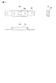
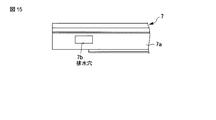
下框7には、中空内にスチール製の断面コ字状の補強材51が設けてあり、補強材51の上端部51aは下框7のガラス間口補強材25にねじ50で固定してあり、下端部51bは下補助板29にねじ30で固定されている。図15に示すように、補強材51が配置されている下框7の下面7aには、その長手方向一端部に排水穴7bが形成されており、図6及び図16に示すように、補強材51には、排水穴7bの位置に対応して穴51dが形成されていると共に穴51dの横にある側壁51cに第11熱膨張耐火材32kが設けてある。
Other embodiments of the present invention will be described below. In the embodiments described below, parts having the same operational effects as those of the above-described first embodiment are denoted by the same reference numerals. A detailed description of the portion is omitted, and the following description will mainly describe differences from the first embodiment.
A second embodiment of the present invention will be described with reference to FIGS. The sash 1 according to the second embodiment is a vertical sliding sash. As shown in FIG. 6, a stay 19 is provided between the upper collar 5 and the upper frame 13 and between the lower collar 7 and the lower frame 15. Is provided.
The upper collar 5 is provided with a steel reinforcing member 49 having a U-shaped cross section in the hollow. The reinforcing member 49 has an upper end portion 49a fixed to the stay 19 with a screw 46 and a lower end portion 49b having a screw. 48 is fixed to the glass front reinforcing member 25. An eighth thermal expansion refractory material 32 h that closes the space between the upper frame 13 is provided on the upper surface of the upper side of the upper casing 5.
The lower rod 7 is provided with a steel reinforcing member 51 having a U-shaped cross section in the hollow, and the upper end portion 51 a of the reinforcing member 51 is fixed to the glass front reinforcing member 25 of the lower rod 7 with a screw 50. The lower end 51b is fixed to the lower auxiliary plate 29 with screws 30. As shown in FIG. 15, a drain hole 7 b is formed at one end in the longitudinal direction of the lower surface 7 a of the lower rod 7 on which the reinforcing material 51 is arranged. As shown in FIGS. A hole 51d is formed in the material 51 corresponding to the position of the drain hole 7b, and an eleventh thermal expansion refractory material 32k is provided on the side wall 51c next to the hole 51d.
下枠15に設けた熱膨張耐火材保持具43は、図14に示すように、下ステー19の配置空間を規定しており、下ステー19の位置決めを兼ねている。また、図6に示すように、第2実施の形態では、下枠15にはスチール製の断面コ字形状の補強材52が設けてあり、下枠15の排水穴42に対向して配置する第5熱膨張耐火材32eはこの補強材52に設けてある。
左右の竪框9、9の外周側面の室外側には、対向する竪枠17との間を塞ぐ第8熱膨張耐火材32hが設けてある。第8熱膨張耐火材32hは、竪框9に嵌合してあり、経年劣化により第8熱膨張耐火材32hが剥がれ落ちるのを防止している。
左右の竪枠17、17には、第8熱膨張耐火材32hに対向する位置に第7熱膨張耐火材32gが設けてあり、火災の熱により第7熱膨張耐火材32gと第8熱膨張耐火材32hが膨張して互いに当接することにより、竪枠17、17と対向する竪框9,9との間を塞ぐようにしてある。尚、第7熱膨張耐火材32gは竪枠17に嵌合してあり、経年劣化により第8熱膨張耐火材32gが剥がれ落ちるのを防止している。
図7に示すように、ハンドル53側の竪框(図7及び図8において右側框)9には、デッドボルト54が設けてある。ハンドル53は樹脂製であり、ハンドル53の取付け部には、図13に示すハンドル台座55が取付けてある。図7及び図8に示すように、ハンドル台座55には、その内周側に第9熱膨張耐火材32iが固定されている。
As shown in FIG. 14, the thermal expansion refractory material holder 43 provided on the lower frame 15 defines an arrangement space for the lower stay 19, and also serves to position the lower stay 19. Further, as shown in FIG. 6, in the second embodiment, the lower frame 15 is provided with a steel-made reinforcing member 52 having a U-shaped cross section, and is disposed to face the drain hole 42 of the lower frame 15. The fifth thermal expansion refractory material 32 e is provided on the reinforcing material 52.
An eighth thermal expansion refractory material 32h is provided on the outer sides of the outer peripheral side surfaces of the left and right rods 9 and 9 so as to close the space between the opposite rod frames 17. The eighth thermal expansion refractory material 32h is fitted to the flange 9 and prevents the eighth thermal expansion refractory material 32h from peeling off due to aging.
The left and right gutter frames 17, 17 are provided with a seventh thermal expansion refractory material 32g at a position facing the eighth thermal expansion refractory material 32h, and the seventh thermal expansion refractory material 32g and the eighth thermal expansion are caused by the heat of the fire. The refractory material 32h expands and comes into contact with each other, so that the space between the flange frames 17 and 17 and the opposite flanges 9 and 9 is closed. Note that the seventh thermal expansion refractory material 32g is fitted to the gutter frame 17 to prevent the eighth thermal expansion refractory material 32g from peeling off due to aging.
As shown in FIG. 7, a dead bolt 54 is provided on the handle 9 (the right handle in FIGS. 7 and 8) on the handle 53 side. The handle 53 is made of resin, and a handle base 55 shown in FIG. As shown in FIGS. 7 and 8, a ninth thermal expansion refractory material 32 i is fixed to the handle base 55 on the inner peripheral side thereof.
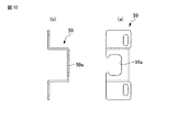
図8に示すように、ハンドル側の竪框9の下部にはスチール製の落下防止具57が設けてあり、対応する竪枠17には、スチール製の落下防止受け59が固定してある。図9及び図10に示すように、落下防止受け59は落下防止具57を上から係合する凹状の係合部59aが形成されている。
ハンドル53を取り付けていない側の竪框9には、図7及び図8に示すように、スチール製の開き防止金具61が設けてあり、対向する竪枠17にはスチール製の受け金具63が取付けてある。開き防止金具61は、図12に示すように竪枠側に突出した突片61aを有し、受け金具63は、図11に示すように室外側壁63a、上壁63b及び下壁63cを有し、開き防止具61が受け金具63から室外側に外れるのを阻止している。開き防止金具61及び受け金具63は、図17に示すように、上下方向の3箇所に設けている。
As shown in FIG. 8, a steel fall prevention tool 57 is provided at the lower part of the handle 9 on the handle side, and a steel fall prevention receiver 59 is fixed to the corresponding saddle frame 17. As shown in FIGS. 9 and 10, the drop prevention receptacle 59 is formed with a concave engagement portion 59 a that engages the fall prevention tool 57 from above.
As shown in FIGS. 7 and 8, the saddle 9 on the side to which the handle 53 is not attached is provided with a steel opening prevention metal fitting 61, and a steel receiving metal fitting 63 is provided on the opposite flange frame 17. It is installed. As shown in FIG. 12, the opening preventing metal fitting 61 has a protruding piece 61a protruding toward the flange frame side, and the receiving metal fitting 63 has an outdoor side wall 63a, an upper wall 63b, and a lower wall 63c as shown in FIG. The opening preventing tool 61 is prevented from coming off the receiving metal 63 to the outdoor side. As shown in FIG. 17, the opening preventing metal fitting 61 and the receiving metal fitting 63 are provided at three locations in the vertical direction.
また、図7及び図8に示すように、左右の竪枠17、17には、各々熱膨張耐火材保持具65を長手方向に設けてあり、熱膨張耐火材保持具65は横断面が略L字形状を成し、見込壁65aを竪枠17の見込方向略中央部にねじ66で固定してあり、室内側に第10熱膨張耐火材32jを保持する保持部65bを備えている。熱膨張耐火材保持部65bは、面を室外側に向けて且つ室内側端を内周側にして傾斜してあり、第10熱膨張耐火材32jは、竪框9の室内側面と見込面とが成すコーナ部9cに対向して設けてある。
Further, as shown in FIGS. 7 and 8, the left and right gutter frames 17, 17 are each provided with a thermal expansion refractory material holder 65 in the longitudinal direction, and the thermal expansion refractory material holder 65 has a substantially transverse cross section. It has an L shape, and a prospective wall 65a is fixed to a substantially central portion of the saddle frame 17 in the prospective direction with a screw 66, and a holding portion 65b for holding the tenth thermal expansion refractory material 32j is provided on the indoor side. The thermal expansion refractory material holding portion 65b is inclined with the surface facing the outdoor side and the indoor side end on the inner peripheral side, and the tenth thermal expansion refractory material 32j Is provided to face the corner portion 9c.
この第2実施の形態によれば、上述した第1実施の形態と同様の作用効果を奏すると共に、枠7には、図6に示すように、障子3の上框5の室内側コーナ部5cに対向する第3熱膨張耐火材32c、下框7の室内側コーナ部7cに対向する第4熱膨張耐火材32d及び図7、図8に示すように、左右の框9、9の室内側コーナ部9cに対向する第10熱膨張耐火材32jを設けてあり、火災時に、枠11の室内側の四周に設けた熱膨張耐火材32c、32d、32jが膨張して障子3の四周における室内側コーナ部5c、7c、9cに室内側から当接して、障子3と枠11との間を塞ぐ。これにより、火災時に障子3と枠11との間から外気が室内に入り込んだり、室内の炎を外に噴出するのを防止できる。
また、上框5の室外側、下框7の室外側、左右の竪框9、9の室外側には第8熱膨張耐火材32hが設けてあり、火災時に室外側における障子3と枠11との間を塞いで、外気が室内に入り込んだり、室内の炎を外に噴出するのを更に防止できる。
図7に示すように、ハンドル台座55に第9熱膨張耐火材32iが設けてあるから、火災時に、樹脂製ハンドル53が溶け落ちても、ハンドル53を取付けてあるハンドル台座55の穴55aを塞ぐことができる。
更に、火災時に、下框7の下面7a形成されている排水穴7bを補強材51に設けた第11熱膨張耐火材32kで塞ぐことができる。
上枠13に設けた第3熱膨張耐火材32c及び下枠15に設けた第4熱膨張耐火材32dに加えて、左右の竪枠17に設けた第10熱膨張耐火材32jも面を室外側に向けて且つ室内側端を内周側に向けて傾斜して、室外側における火災時の熱を面で受け易くしているから、火災時に障子の四周で枠との間を早期に塞ぐことができる。
According to the second embodiment, the same effects as those of the first embodiment described above can be obtained, and the frame 7 has an indoor corner portion 5c of the upper arm 5 of the shoji 3 as shown in FIG. The third thermal expansion refractory material 32c opposite to the inner wall, the fourth thermal expansion refractory material 32d opposite to the indoor corner portion 7c of the lower rod 7, and the indoor side of the left and right rods 9, 9 as shown in FIGS. The tenth thermal expansion refractory material 32j facing the corner portion 9c is provided, and the thermal expansion refractory materials 32c, 32d, and 32j provided on the four inner sides of the frame 11 expand in the event of a fire, and the chambers on the four sides of the shoji 3 The inner corner portions 5c, 7c, and 9c are in contact with the inner side from the room side, and the space between the shoji 3 and the frame 11 is closed. Thereby, it is possible to prevent outside air from entering the room from between the shoji 3 and the frame 11 in the event of a fire or blowing out the indoor flame.
Further, an eighth thermal expansion refractory material 32h is provided on the outdoor side of the upper rod 5, the outdoor side of the lower rod 7, and the outdoor sides of the left and right rods 9, 9, and the shoji 3 and the frame 11 on the outdoor side in the event of a fire. It is possible to further prevent the outside air from entering the room and blowing out the indoor flame to the outside.
As shown in FIG. 7, since the ninth thermal expansion refractory material 32i is provided on the handle base 55, even if the resin handle 53 melts down in the event of a fire, the hole 55a of the handle base 55 to which the handle 53 is attached is provided. Can be closed.
Furthermore, at the time of a fire, the drain hole 7b formed in the lower surface 7a of the lower rod 7 can be closed with the eleventh thermal expansion refractory material 32k provided in the reinforcing material 51.
In addition to the third thermal expansion refractory material 32 c provided on the upper frame 13 and the fourth thermal expansion refractory material 32 d provided on the lower frame 15, the tenth thermal expansion refractory material 32 j provided on the left and right frame 17 also has a surface. Inclined toward the outside and the indoor side end toward the inner circumference, making it easier for the surface to receive heat from the fire at the outside of the room. be able to.
図8に示すように、ハンドル53が取り付けてある竪框9には、落下防止金具57が設けてあり、対向する枠17には落下防止金具受け59を設けているので、火災時における障子3の落下を防止できる。
また、他方の竪框9bには、図7及び図8に示すように、開き防止金具61を設けてあり、対向する竪枠17には受け金具63が設けてあるので、火災時に障子3が回転して開くのを防止できる。
As shown in FIG. 8, the saddle 9 to which the handle 53 is attached is provided with a fall-preventing bracket 57, and the opposing frame 17 is provided with a fall-preventing bracket receiver 59. Can be prevented from falling.
Moreover, as shown in FIG.7 and FIG.8, the other guard 9b is provided with the opening prevention metal fitting 61, and since the opposite metal frame 17 is provided with the receiving metal 63, the shoji 3 is attached in the event of a fire. It can be prevented from rotating and opening.
図18を参照して、本発明の第3実施の形態を説明する。図18は第3実施の形態にかかるサッシ1の下枠15及び下框7を示したものであり、第4熱膨張耐火材32dは、下框7の室内側見付け面と見込み面とのコーナ部7cに対向して配置してあり、火災時期に膨張してアルミニウム製の下框7のコーナ部7cに当接するようにしたものである。また、第4熱膨張耐火材32dは、熱膨張耐火材保持具43に嵌合固定してあり、経年劣化による脱落を防止してある。
この第3実施の形態においても、上述した第1実施の形態と同様の作用効果を奏することができる。
A third embodiment of the present invention will be described with reference to FIG. FIG. 18 shows the lower frame 15 and the lower rod 7 of the sash 1 according to the third embodiment, and the fourth thermal expansion refractory material 32d is a corner between the indoor-side finding surface and the prospective surface of the lower rod 7. It is arranged so as to face the portion 7c, and expands during a fire period so as to come into contact with the corner portion 7c of the lower arm 7 made of aluminum. Further, the fourth thermal expansion refractory material 32d is fitted and fixed to the thermal expansion refractory material holder 43, and is prevented from falling off due to deterioration over time.
Also in the third embodiment, the same operational effects as those of the first embodiment described above can be achieved.
本発明によれば、第3熱膨張耐火材32c、第4熱膨張耐火材32d及び第10熱膨張耐火材32jは、面を室外側に向けて且つ室内側端を内周側に向けて傾斜して設けてあるので、室外側の熱を面で受け易く、火災発生時に早期に面全体が膨張して室内側から対向する框に当接して、枠11と障子3との間を塞ぐことができる。これにより、火災時に框5、7、9と枠11との間から外気が室内に入り込んだり、室内の炎を外に噴出するのを防止できる。また、第3熱膨張耐火材32c、第4熱膨張耐火材32d及び第10熱膨張耐火材32jは、火災の熱により膨張して室内側から障子3の見込面と室内側見付面とのコーナ部5c、7cに当接する位置にあるから、障子3との距離が最も近い位置に配置でき、火災時に膨張したときに枠11と障子3との隙間を確実に且つ容易に塞ぐことができる。更に、枠11に第3熱膨張耐火材32c、第4熱膨張耐火材32d及び第10熱膨張耐火材32jを保持する熱膨張耐火材保持具43、65を設けて、熱膨張耐火材保持具43、65は枠11の見込面にねじで固定してあるから、框のコーナ部5c、7c、9cに対向する位置に面を室外側に向けて且つ室内側端を内周側に向けて傾斜した第3熱膨張耐火材32c、第4熱膨張耐火材32d及び第10熱膨張耐火材32jを配置することが、簡易な構成で容易にできる。
また、サッシがすべり出しサッシや開きサッシ等のスイング系サッシである場合は、特に、サッシ1の枠11は、火災時に室外側から火が入り易い為に、室外側から受けた熱により熱膨張耐火材32c、32d、32jが火災発生時に早期に膨張できることで、防火性能を効果的に高めることができる。
According to the present invention, the third thermal expansion refractory material 32c, the fourth thermal expansion refractory material 32d, and the tenth thermal expansion refractory material 32j are inclined with the surface facing the outdoor side and the indoor side end facing the inner peripheral side. It is easy to receive the heat of the outdoor side by the surface, and when the fire breaks out, the entire surface expands quickly and abuts against the ridge facing from the indoor side to block between the frame 11 and the shoji 3 Can do. Thereby, it is possible to prevent outside air from entering the room from between the fences 5, 7, 9 and the frame 11 in the event of a fire or blowing out the flame in the room to the outside. Further, the third thermal expansion refractory material 32c, the fourth thermal expansion refractory material 32d, and the tenth thermal expansion refractory material 32j are expanded by the heat of the fire, and the expected surface of the shoji 3 and the indoor side finding surface from the indoor side. Since the corners 5c and 7c are in contact with each other, the distance from the shoji 3 can be arranged at the closest position, and the space between the frame 11 and the shoji 3 can be reliably and easily closed when the shoji 3 is expanded in the event of a fire. . Further, the frame 11 is provided with thermal expansion refractory holders 43 and 65 for holding the third thermal expansion refractory material 32c, the fourth thermal expansion refractory material 32d, and the tenth thermal expansion refractory material 32j. Since 43 and 65 are fixed to the prospective surface of the frame 11 with screws, the surface faces the outdoor side and the indoor side end faces the inner peripheral side at a position facing the corners 5c, 7c, and 9c of the heel. The inclined third thermal expansion refractory material 32c, fourth thermal expansion refractory material 32d, and tenth thermal expansion refractory material 32j can be easily arranged with a simple configuration.
In addition, when the sash is a sliding sash such as a sliding sash or an open sash, the frame 11 of the sash 1 is easily ignited from the outside in the event of a fire. Since the materials 32c, 32d, and 32j can expand at an early stage in the event of a fire, the fireproof performance can be effectively enhanced.
本発明は、上述した実施の形態に限らず、本発明の要旨を逸脱しない範囲で種々変形可能である。
例えば、第1及び第2実施の形態において、下框7の補助板29はスチール材に限らず、アルミニウム等の他の金属材やカーボン材であっても良く、樹脂製形材6よりも融点が高いものであれば良い。
第1実施の形態において、上框5には上補助板31を設けずに、下框7にのみ下補助板29を設けるものであっても良い。
サッシ1はすべり出しサッシや、横すべり出しサッシに限らず、外倒しサッシ、突き出しサッシ、開きサッシ、回転サッシ、引き違いサッシ、片引きサッシ、FIXサッシ等のサッシであっても良い。
また、サッシ1は、障子3の輪郭が丸形であっても良く、障子3の形状は限定されない。
The present invention is not limited to the above-described embodiment, and various modifications can be made without departing from the scope of the present invention.
For example, in the first and second embodiments, the auxiliary plate 29 of the lower arm 7 is not limited to a steel material, but may be another metal material such as aluminum or a carbon material, and has a melting point higher than that of the resin shaped material 6. As long as the is high.
In the first embodiment, the upper auxiliary plate 31 may be provided only on the lower rod 7 without providing the upper auxiliary plate 31 on the upper rod 5.
The sash 1 is not limited to a sliding sash or a side sliding sash, and may be a sash such as an overturned sash, a protruding sash, an open sash, a rotating sash, a sliding sash, a single-drawing sash, a FIX sash, and the like.
Moreover, the sash 1 may have a round outline of the shoji 3, and the shape of the shoji 3 is not limited.