JP6282911B2 - Film thickness measuring apparatus and film thickness measuring method - Google Patents
Film thickness measuring apparatus and film thickness measuring method Download PDFInfo
- Publication number
- JP6282911B2 JP6282911B2 JP2014058832A JP2014058832A JP6282911B2 JP 6282911 B2 JP6282911 B2 JP 6282911B2 JP 2014058832 A JP2014058832 A JP 2014058832A JP 2014058832 A JP2014058832 A JP 2014058832A JP 6282911 B2 JP6282911 B2 JP 6282911B2
- Authority
- JP
- Japan
- Prior art keywords
- optical path
- path difference
- incident angle
- film thickness
- measurement position
- Prior art date
- Legal status (The legal status is an assumption and is not a legal conclusion. Google has not performed a legal analysis and makes no representation as to the accuracy of the status listed.)
- Expired - Fee Related
Links
Images


Description
本発明の実施形態は、反射干渉光を用いて薄膜の膜厚を測定する膜厚測定装置および膜厚測定方法に関する。 Embodiments described herein relate generally to a film thickness measuring apparatus and a film thickness measuring method for measuring a film thickness of a thin film using reflected interference light.
薄膜の膜厚の測定方法の1つに、薄膜の表面反射光と裏面反射光との光路差により生じる反射干渉光を利用する反射率分光法がある。たとえば特開2013−79921号公報(特許文献1)には、異なる入射角の2方向から測定した反射干渉光を用いる方法(以下、2方向反射率分光法という)により、屈折率が未知の薄膜の膜厚を測定する技術が開示されている。 One method for measuring the thickness of a thin film is reflectance spectroscopy that uses reflected interference light generated by the optical path difference between the front surface reflected light and the back surface reflected light of the thin film. For example, Japanese Unexamined Patent Application Publication No. 2013-79921 (Patent Document 1) discloses a thin film having an unknown refractive index by a method using reflected interference light measured from two directions at different incident angles (hereinafter referred to as two-way reflectance spectroscopy). A technique for measuring the film thickness of the film is disclosed.
誘電体薄膜の充填率(見かけの充填率)は作製条件によって変化する。一方、薄膜の屈折率は充填率によって変化する。このため、薄膜の屈折率は、作製条件によって変化する。2方向反射率分光法によれば、この種の屈折率が未知な誘電体薄膜の膜厚を測定することができ、便利である。 The filling factor (apparent filling factor) of the dielectric thin film varies depending on the manufacturing conditions. On the other hand, the refractive index of the thin film varies depending on the filling rate. For this reason, the refractive index of a thin film changes with manufacturing conditions. The two-way reflectance spectroscopy is convenient because it can measure the thickness of a dielectric thin film whose refractive index is unknown.
ところで、ユーザは、移動中の薄膜を移動するままに検査したいと所望することがある。たとえば、観測対象となる薄膜が形成された試料の作製現場では、次々に作製される試料は、ベルトコンベア上に載置されて試料の製造装置から離れた場所へ移動させられる場合がある。この場合、ユーザは、検査の効率性などを考慮し、ベルトコンベア上で移動中の試料の薄膜を移動するままに検査したいと所望することがある。 By the way, the user may desire to inspect the moving thin film as it moves. For example, in a production site of a sample on which a thin film to be observed is formed, samples produced one after another may be placed on a belt conveyor and moved to a place away from the sample manufacturing apparatus. In this case, the user may desire to inspect the thin film of the sample being moved on the belt conveyor in consideration of the inspection efficiency.
しかし、2方向反射率分光法により薄膜の膜厚を測定する従来の技術では、両方向における薄膜上の観測点が同一であること、すなわち同一の膜厚および同一の屈折率に対応する反射干渉光が測定されていることを前提としている。また、各方向の反射干渉光測定は、もう一方からの入射光や反射光の干渉を避けるため、互いにタイミングをずらして行われる。 However, in the conventional technique of measuring the film thickness of the thin film by two-way reflectance spectroscopy, the observation points on the thin film in both directions are the same, that is, the reflected interference light corresponding to the same film thickness and the same refractive index. Is assumed to be measured. Further, the reflected interference light measurement in each direction is performed with the timing shifted from each other in order to avoid interference of incident light and reflected light from the other direction.
このため、従来の技術では、観測対象となる薄膜が移動し続けている場合、2方向のそれぞれで異なる位置の反射干渉光を観測することになってしまう。したがって、従来の技術では観測対象となる薄膜が移動している場合には正確な膜厚を求めることができない。 For this reason, in the conventional technique, when the thin film to be observed continues to move, reflected interference light at different positions in each of the two directions is observed. Therefore, in the conventional technique, an accurate film thickness cannot be obtained when a thin film to be observed is moving.
本発明は、上述した事情を考慮してなされたもので、薄膜が移動している場合であっても、屈折率が未知の薄膜の膜厚を正確に測定することができる膜厚測定装置および膜厚測定方法を提供することを目的とする。 The present invention has been made in consideration of the above-described circumstances, and a film thickness measuring apparatus capable of accurately measuring the film thickness of a thin film whose refractive index is unknown even when the thin film is moving, and It aims at providing the film thickness measuring method.
本発明の一実施形態に係る膜厚測定装置は、上述した課題を解決するために、薄膜の表面反射光と裏面反射光との光路差により生じる反射干渉光の波長分布にもとづいて薄膜の膜厚を測定する膜厚測定装置であって、照射部、受光部、光路差算出部、光路差補間部および膜厚屈折率算出部を備えたものである。照射部は、互いに異なる入射角で所定の照射位置に対して所定の時間間隔で交互に照射光を照射することにより、所定の照射位置を通過する薄膜上の複数の計測位置のそれぞれに対して互いに異なる入射角で交互に照射光を照射する。受光部は、複数の計測位置のそれぞれにおける照射光の反射干渉光を、所定の照射位置を複数の計測位置のそれぞれが通過するにともない互いに異なる入射角に対応する互いに異なる反射角で交互に受光する。光路差算出部は、複数の計測位置のそれぞれについて、各計測位置に対して照射光が照射された入射角で得られた反射干渉光の波長分布を用いて光路差を求める。光路差補間部は、複数の計測位置のそれぞれについて、一方の入射角で照射光が照射された計測位置に対して他方の入射角で照射光が照射されたと仮定した場合に推定される光路差を、当該計測位置から所定距離内の計測位置で光路差算出部により求められた光路差を用いて補間する。膜厚屈折率算出部は、複数の計測位置のそれぞれについて、入射角、膜厚および屈折率を変数とした関数として光路差を表した式を用いて、一方の入射角および光路差算出部により求められた光路差、ならびに他方の入射角および光路差補間部により求められた光路差を式に代入することにより、各計測位置における薄膜の膜厚および屈折率を求める。 In order to solve the above-described problem, a film thickness measuring apparatus according to an embodiment of the present invention is based on the wavelength distribution of reflected interference light generated by the optical path difference between the front surface reflected light and the back surface reflected light of the thin film. A film thickness measuring apparatus that measures thickness, and includes an irradiation unit, a light receiving unit, an optical path difference calculation unit, an optical path difference interpolation unit, and a film thickness refractive index calculation unit. The irradiating unit alternately irradiates irradiation light at predetermined time intervals at predetermined incident positions at different incident angles, thereby each of a plurality of measurement positions on the thin film passing through the predetermined irradiation position. Irradiation light is alternately irradiated at different incident angles. The light receiving unit alternately receives the reflected interference light of the irradiation light at each of the plurality of measurement positions at different reflection angles corresponding to different incident angles as each of the plurality of measurement positions passes through the predetermined irradiation position. To do. The optical path difference calculation unit obtains an optical path difference for each of the plurality of measurement positions using the wavelength distribution of the reflected interference light obtained at the incident angle at which the irradiation light is irradiated to each measurement position. The optical path difference interpolation unit estimates the optical path difference when it is assumed that the irradiation light is irradiated at the other incident angle with respect to the measurement position irradiated with the irradiation light at one incident angle for each of the plurality of measurement positions. Is interpolated using the optical path difference obtained by the optical path difference calculation unit at a measurement position within a predetermined distance from the measurement position. The film thickness refractive index calculation unit uses an expression representing the optical path difference as a function of the incident angle, the film thickness, and the refractive index as variables for each of a plurality of measurement positions. The film thickness and refractive index of the thin film at each measurement position are obtained by substituting the obtained optical path difference, and the other incident angle and the optical path difference obtained by the optical path difference interpolation unit into the equation.
本発明に係る膜厚測定装置および膜厚測定方法の実施の形態について、添付図面を参照して説明する。 Embodiments of a film thickness measuring apparatus and a film thickness measuring method according to the present invention will be described with reference to the accompanying drawings.
本発明の一実施形態に係る膜厚測定装置は、照射光の照射領域内を通過する薄膜に対して互いに異なる2種の入射角θAおよびθBで照射光を入射し、この2種の入射光に対応する薄膜の反射干渉光の波長分布にもとづいて薄膜の膜厚を測定するものである。 The film thickness measurement apparatus according to an embodiment of the present invention irradiates irradiation light at two different incident angles θA and θB with respect to the thin film passing through the irradiation region of the irradiation light, and the two types of incident light. The film thickness of the thin film is measured based on the wavelength distribution of the reflected interference light of the thin film corresponding to.
(1.概略構成)
図1は、本発明の一実施形態に係る膜厚測定装置10の一例を示す概略的な全体構成図である。なお、以下の説明では、薄膜の法線方向をZ軸、薄膜の法線方向に垂直かつ薄膜の移動方向をX軸とする場合の例について示す。
(1. Outline configuration)
FIG. 1 is a schematic overall configuration diagram showing an example of a film
膜厚測定装置10は、照射部11、受光部12、分光部13、コンベヤ14、作製装置15および情報処理装置16を有する。なお、本実施形態に係る膜厚測定装置10の膜厚および屈折率の算出処理において情報処理装置16の主制御部を除く構成は同処理において必須の構成ではなく適宜省略されてもよい。たとえば薄膜の反射干渉光データがネットワークを介して受信可能な場合には、情報処理装置16を除く構成は同処理において不要である。
The film
照射部11は、光源20、第1の照射ユニット21および第2の照射ユニット22を有する。
The
光源20は、ハロゲンランプや広帯域レーザなどにより構成され、所定の波長範囲を有する照射光を出射し、この照明光を光ファイバなどにより構成されるライトガイド23を介してそれぞれ第1の照射ユニット21および第2の照射ユニット22に与える。また、第1の照射ユニット21および第2の照射ユニット22の光源20側の光路上には、それぞれシャッタ24および25が設けられる。
The
第1の照射ユニット21および第2の照射ユニット22は、対象物26に対し、互いに異なる第1の入射角θAおよび第2の入射角θBで所定の時間間隔で交互に照射光を照射する。対象物26は、基板27を有し、基板27の表面には薄膜28が形成される。
The
シャッタ24および25は、情報処理装置16により制御されて、第1の照射ユニット21による対象物26に対する照射光の照射と第2の照射ユニット22による対象物26に対する照射光の照射が所定の時間間隔で交互に行われるよう、照射光を適宜遮蔽する。
The
受光部12は、第1の受光ユニット31および第2の受光ユニット32を有する。
The
第1の受光ユニット31は、薄膜28の表面の法線を介して第1の照射ユニット21に対向する位置に配置される。第1の受光ユニット31は、第1の照射ユニット21により第1の入射角θAで薄膜28に照射された光の薄膜28による第1の反射干渉光を、第1の入射角θAにほぼ等しい第1の反射角で受光する。また、第2の受光ユニット32は、薄膜28の表面の法線を介して第2の照射ユニット22に対向する位置に配置される。第2の受光ユニット32は、第2の照射ユニット22により第2の入射角θBで薄膜28に照射された光の薄膜28による第2の反射干渉光を、第2の入射角θBにほぼ等しい第2の反射角で受光する。
The first
なお、入射角θAおよびθBの一方を0度とする場合は、ビームスプリッタを用いるとよい。たとえば入射角θAを0度とする場合、第1の受光ユニット31は、薄膜28の表面の法線を介して第1の照射ユニット21に対向する位置には配置されない。この場合、たとえば第1の照射ユニット21がX軸に平行に配置され、第1の受光ユニット31が薄膜28の法線上に配置される。このとき、第1の照射ユニット21からX軸に平行に出射された照射光は、ビームスプリッタを介してZ軸に平行に(薄膜28の法線に平行に)薄膜28に向かって反射されることにより、入射角0度で薄膜28に照射される。そして第1の反射干渉光は、反射角0度で(Z軸に平行に)反射されてビームスプリッタを透過し、第1の受光ユニット31により受光される。
If one of the incident angles θA and θB is 0 degree, a beam splitter may be used. For example, when the incident angle θA is set to 0 degree, the first
分光部13は、一般的な分光器により構成され、ライトガイド33を介して第1の受光ユニット31により受光された反射干渉光および第2の受光ユニット32により受光された反射干渉光を交互に受ける。分光部13は、反射干渉光のそれぞれを所定の波長帯域で分光して、波長ごとの反射干渉光の強度の情報を情報処理装置16に与える。
The
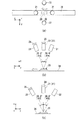
図2(a)は、薄膜28が所定の照射位置35を等速で通過する様子の一例を示すz方向矢視図であり、(b)は、y方向矢視図、(c)はx方向矢視図である。以下の説明では、第1の入射角θAが20度、第2の入射角θBが30度である場合の例について示す。図2(a)、(b)、(c)において、薄膜はそれぞれ右から左、右から左、紙面奥から手前へ移動する。
FIG. 2A is a z-direction arrow view showing an example of how the
なお、便宜上、図2(a)においてはシャッタ24、25の図示を省略した。また図2(b)においては第2の照射ユニット22および第2の受光ユニット32が、(c)においては第1の照射ユニット21および第1の受光ユニット31が、それぞれ紙面の奥行方向に重畳していることに注意する。
For convenience, the illustration of the
図2に示すように、薄膜28を有する対象物26は、コンベヤ14のベルト(載置部)36に載置され、第1の照射ユニット21および第2の照射ユニット22の照射位置35を一定速度で通過する。
As shown in FIG. 2, the
コンベヤ14は、1組のローラ対と、このローラ対に掛け渡された無端状のベルト36とから構成されており、図示しない駆動部により駆動されるようになっている。情報処理装置16は、駆動部を制御することにより薄膜28の移動速度を制御する。
The
作製装置15は、所定の作製条件に従って対象物26を作製するための装置である。作製装置15の対象物26の作製ラインの載置部36aは、コンベヤ14のベルト36と連結され、ベルト36と同じ速度で対象物26を移動させる。
The
本実施形態に係る対象物26の薄膜28としては、たとえば、所定の粒径を有する酸化チタンなどの誘電体により構成された膜や、接着剤や、ITO(Indium Tin Oxide)などの透明電極膜などを用いることができる。誘電体薄膜の場合、膜の充填率(見かけの充填率)は作製条件によって変化する。たとえば対象物26が色素増感太陽電池自体である場合または色素増感太陽電池の物性を検査するための試料である場合、作製装置15は、薄膜28として、色素増感太陽電池の光電極に用いられる酸化チタン薄膜28を基板27上に形成する。
As the
酸化チタン薄膜28は、たとえば酸化チタンのナノ粒子を所定の温度で加熱して得られる多孔質膜である。この種の焼成や焼結により得られる多孔質膜の充填率は、加熱温度、加熱時間などの作製条件に応じて変化することが知られている。また、多孔質膜の屈折率は、充填率に応じて異なることが知られている。このため、酸化チタン薄膜28の屈折率は、作製条件によって変化する。
The titanium oxide
そこで、本実施形態に係る情報処理装置16は、この種の屈折率が未知な薄膜28を移動させながらであっても、薄膜28の膜厚および屈折率を正確に測定可能に構成される。
Therefore, the
情報処理装置16は、たとえばデスクトップ型やノートブック型のパーソナルコンピュータやワークステーションなどにより構成することができる。情報処理装置16は、入力部51、表示部52、記憶部53および主制御部54を有する。
The
入力部51は、たとえばキーボード、トラックボール、タッチパネル、テンキーなどの一般的な入力装置により構成され、ユーザの操作に対応した操作入力信号を主制御部54に出力する。表示部52は、たとえば液晶ディスプレイやOLED(Organic Light Emitting Diode)ディスプレイなどの一般的な表示出力装置により構成され、主制御部54の制御に従って各種情報を表示する。記憶部53は、CPUにより読み書き可能な記憶媒体である。記憶部53は、あらかじめ、入射角、膜厚および屈折率を変数とした関数として光路差Lを表した式を記憶している。
The
主制御部54は、分光部13から反射干渉光の分光スペクトルを受け、この分光スペクトルを用いて光路差Lを求める。また、主制御部54は、記憶部53に記憶された式を用いて薄膜28の計測位置ごとに膜厚および屈折率を求める。主制御部54の構成および動作の詳細については後述する。
The
(2.薄膜の計測位置)
図3(a)は、本実施形態に係る照射光スポットエリア(所定の照射位置35)のサイズと受光スポットエリア37のサイズの関係の一例を示す説明図であり、(b)は所定の照射位置35と計測位置の関係の一例を示す説明図である。
(2. Measurement position of thin film)
FIG. 3A is an explanatory diagram showing an example of the relationship between the size of the irradiation light spot area (predetermined irradiation position 35) and the size of the light receiving
干渉信号を効率的に集光するためには、照射光スポットエリア35の半径r1よりも受光スポットエリア37の半径r2のほうが大きいことが好ましい(図3(a)参照)。照射光スポットエリア35の半径r1は、照射ユニット21および22を構成するレンズの開口数などを調整することにより制御できる。また、受光スポットエリア37の半径r2は、受光ユニット31および32を構成するレンズの開口数などを調整することにより制御できる。
In order to efficiently collect the interference signal, it is preferable that the radius r2 of the light receiving
薄膜28は、ベルト36に載置されて、照射位置35を通過する。一方、第1の照射ユニット21および第2の照射ユニット22は、互いに異なる第1の入射角θAおよび第2の入射角θBで、照射位置35に対して所定の時間間隔で交互に照射光を照射する。このため、薄膜28上の計測位置X1、X2、・・・、Xn−1、Xn、Xn+1、・・・Xm(ただし、mは正整数、nは偶数をあらわす)の隣り合う計測位置どうしは、互いに異なる入射角から照射光を照射されることになる。
The
情報処理装置16は、ベルト36の速度およびシャッタ24、25を制御することにより、計測位置および計測位置どうしの間隔を制御することができる。
The
以下の説明では、第1の入射角θAで照射光が照射される計測位置をXn−1(A)、第2の入射角θBで照射光が照射される計測位置をXn(B)とあらわすものとする(図3(b)参照)。また、Xn−1(A)で得られた反射干渉光の波長分布を用いて求められた光路差を光路差Ln−1(A)、Xn(B)で得られた反射干渉光の波長分布を用いて求められた光路差を光路差Ln(B)とあらわすものとする。 In the following description, the measurement position where the irradiation light is irradiated at the first incident angle θA is expressed as Xn-1 (A), and the measurement position where the irradiation light is irradiated at the second incident angle θB is expressed as Xn (B). It shall be (refer FIG.3 (b)). In addition, the optical path difference obtained by using the wavelength distribution of the reflected interference light obtained by Xn-1 (A) is changed to the wavelength distribution of the reflected interference light obtained by the optical path differences Ln-1 (A) and Xn (B). The optical path difference obtained using is expressed as an optical path difference Ln (B).
なお、反射干渉光の高強度化を目指すため、図3(a)に示す方法に代えてまたは加えて、薄膜28の測定エリアサイズを狭くしてもよいし、薄膜28の構成粒子の粒径に応じた光源波長および入射角を用いてもよいし、あらかじめ基板27のみの反射率を測定し、その結果から反射率の大きい測定波長を用いてもよい(たとえば特開2013−79921号公報参照)。
In order to increase the intensity of the reflected interference light, the measurement area size of the
(3.主制御部の構成)
主制御部54は、CPU、RAMおよびROMをはじめとする記憶媒体などにより構成され、この記憶媒体に記憶されたプログラムに従って膜厚測定装置10の動作を制御する。主制御部54のCPUは、ROMをはじめとする記憶媒体に記憶された膜厚測定プログラムおよびこのプログラムの実行のために必要なデータをRAMへロードする。CPUは、このプログラムに従って、薄膜28が移動している場合であっても、屈折率が未知の薄膜28の膜厚を正確に測定するための処理を実行する。
(3. Configuration of main control unit)
The
主制御部54のRAMは、CPUが実行するプログラムおよびデータを一時的に格納するワークエリアを提供する。主制御部54のROMをはじめとする記憶媒体は、情報処理装置16の起動プログラム、膜厚測定プログラムや、これらのプログラムを実行するために必要な各種データを記憶する。
The RAM of the
なお、ROMをはじめとする記憶媒体は、磁気的もしくは光学的記録媒体または半導体メモリなどの、CPUにより読み取り可能な記録媒体を含んだ構成を有する。これら記憶媒体内のプログラムおよびデータの一部または全部は電子ネットワークを介してダウンロードされるように構成してもよい。 Note that a storage medium such as a ROM has a configuration including a CPU-readable recording medium such as a magnetic or optical recording medium or a semiconductor memory. You may comprise so that a part or all of the program and data in these storage media may be downloaded via an electronic network.
図4は、主制御部54のCPUによる機能実現部の構成例を示す概略的なブロック図である。なお、この機能実現部は、CPUを用いることなく回路などのハードウエアロジックによって構成してもよい。
FIG. 4 is a schematic block diagram illustrating a configuration example of the function realization unit by the CPU of the
図4に示すように、主制御部54のCPUは、膜厚測定プログラムによって、少なくとも駆動制御部61、シャッタ制御部62、波長分布生成部63、光路差算出部64、光路差補間部65、膜厚屈折率算出部66および充填率算出部67として機能する。この各部61−67は、RAMの所要のワークエリアをデータの一時的な格納場所として利用する。
As shown in FIG. 4, the CPU of the
駆動制御部61は、コンベヤ14の駆動部を制御することにより、薄膜28の移動速度を制御する。
The
シャッタ制御部62は、一の入射角による反射干渉光が他の入射角による反射干渉光に混入する弊害を未然に防ぐよう、所定の照射位置35に対して第1の照射ユニット21および第2の照射ユニット22から所定の時間間隔で交互に照射光が照射されるようにシャッタ24および25を制御する。
The
図5は、波長分布生成部63により生成される、反射干渉光の波長分布の一例を示す説明図である。図5には、膜厚d=16μm、屈折率n=1.6を目標に作製された薄膜28について波長分布生成部63により生成された波長分布の一例を示した。図5において、実線は第1の入射角θA=20度に対応する計測位置Xn−1(A)における波長分布の一例を、破線は第2の入射角θB=30度に対応する計測位置Xn(B)における波長分布の一例を、それぞれ示す。
FIG. 5 is an explanatory diagram illustrating an example of the wavelength distribution of the reflected interference light generated by the wavelength
波長分布生成部63は、分光部13により生成された各波長における反射干渉光の強度の情報にもとづいて、各計測位置Xnのそれぞれについて、所定の波長帯域ごとのデータからなる離散的な波長分布を生成する(図5参照)。
Based on the information on the intensity of the reflected interference light at each wavelength generated by the
光路差算出部64は、複数の計測位置X1(A)、X2(B)、・・・、Xmのそれぞれについて、各計測位置に対して照射光が照射された入射角で得られた反射干渉光の波長分布を用いて光路差L(以下、適宜実測光路差Lという)を求める。
The optical path
たとえば、計測位置Xn(B)は、入射角θBにより照射光が照射される計測位置である。この計測位置Xn(B)の光路差Ln(B)について、光路差算出部64は、計測位置Xn(B)で得られた反射干渉光の波長分布を用いて求める。
For example, the measurement position Xn (B) is a measurement position where irradiation light is irradiated at an incident angle θB. The optical path
光路差補間部65は、複数の計測位置X1(A)、X2(B)、・・・、Xmのそれぞれについて、一方の入射角で照射光が照射された計測位置に対して他方の入射角で前記照射光が照射されたと仮定した場合に推定される光路差である光路差(補間光路差)L’を、当該計測位置から所定距離内の計測位置で光路差算出部64により求められた光路差Lを用いて求める。
The optical path
たとえば、計測位置Xn(B)について考える。計測位置Xn(B)は、入射角θBによる照射光で反射干渉光が実測される計測位置である。このため、光路差算出部64が算出する実測光路差Ln(B)は、入射角θBによる照射光で実測された反射干渉光の波長分布を用いて求められたものである。換言すれば、計測位置Xn(B)に対しては、入射角θAからの光は照射されていない。光路差補間部65は、計測位置Xn(B)に対して入射角θAで照射光が照射されたと仮定した場合に推定される補間光路差L’n(A)を、計測位置Xn(B)から所定距離内の計測位置で光路差算出部64により求められた実測光路差Lを用いて求める。
For example, consider the measurement position Xn (B). The measurement position Xn (B) is a measurement position where the reflected interference light is actually measured with the irradiation light with the incident angle θB. For this reason, the actually measured optical path difference Ln (B) calculated by the optical path
膜厚屈折率算出部66は、複数の計測位置のそれぞれについて、記憶部53に記憶された式を用いて、実測した入射角および光路差算出部64により求められた実測光路差L、ならびに実測していない入射角および光路差補間部65により求められた補間光路差L’を式に代入することにより、各計測位置における薄膜28の膜厚dおよび屈折率nを求め、その結果を表示部52に表示する。
The film thickness refractive
充填率算出部67は、膜厚屈折率算出部66により求められた屈折率nを用いて、薄膜28の各計測位置における薄膜28の構成材料の充填率を求める。
The filling
(3−1.実測光路差Lの算出方法)
光路差算出部64は、薄膜28の表面と裏面、および多層膜であればその界面各々で反射された光の干渉(反射干渉光)の波長分布を用いて実測光路差Lを算出する。従来、反射干渉光の波長分布を用いた光路差Lの算出方法として種々の方法が知られており、光路差算出部64は、これらのうち任意のものを使用することができる。
(3-1. Calculation Method of Actual Optical Path Difference L)
The optical path
図6は、薄膜28の表面反射光と裏面反射光の光路差Lを説明するための図である。
FIG. 6 is a diagram for explaining the optical path difference L between the front surface reflected light and the back surface reflected light of the
照射光が薄膜28の表面28aに入射角θ1で入射する場合、膜厚をd、屈折角をθ2とすると、薄膜表面28aでの反射光(表面反射光)と薄膜裏面28bでの反射光(裏面反射光)との行程差ΔSは次のように書ける。
![]()
![]()
薄膜28の屈折率をnとすると、光路差Lは、行程差ΔSに屈折率nを乗じたものである。
![]()
![]()
基板27の屈折率が薄膜28の屈折率より大きい場合、光路差Lと反射干渉光のピーク波長λmには次の式(3)の関係があることが知られている。
![]()
![]()
このため、反射干渉光の波長分布は、各mに対応する複数のピークを有する波形となる(図5参照)。なお、基板27の屈折率が薄膜28の屈折率より小さい場合には界面反射の際に位相反転が起きるため、式(3)に代えてL=(m+1/2)・λmを用いればよい。
For this reason, the wavelength distribution of the reflected interference light has a waveform having a plurality of peaks corresponding to each m (see FIG. 5). When the refractive index of the
したがって、光路差算出部64は、式(3)を用いて、各計測位置について、反射干渉光の波長分布(図5参照)のピークの波長から実測光路差Lを求めることができる。ピーク位置を求める方法には、従来、フーリエ変換を用いる方法、カーブフィッティング法や、ピークバレー法などがあり、これらのいずれを用いてもよい。
Therefore, the optical path
また、光路差算出部64は、反射干渉光の波長分布に対して離散フーリエ変換を行うことにより実測光路差Lを求めてもよいし(特開2013−79921号公報参照)、反射干渉光の波長分布に対して所定のテンプレート波形を用いた正規化相関演算を行うことにより実測光路差Lを求めてもよい(特開2013−253803号公報参照)。
Further, the optical path
(3−2.補間光路差L’の算出方法)
図7(a)は薄膜28の膜厚dおよび屈折率nが計測位置によらず均一な場合の計測位置と光路差との関係の一例を示す説明図であり、(b)は不均一な場合の計測位置と光路差との関係の一例を示す説明図である。
(3-2. Method for calculating interpolation optical path difference L ′)
FIG. 7A is an explanatory diagram showing an example of the relationship between the measurement position and the optical path difference when the film thickness d and the refractive index n of the
図7(a)に示すように、薄膜28の膜厚dおよび屈折率nが計測位置によらず均一であれば、入射角θAおよびθBのそれぞれについて適当な1箇所ずつの計測位置でそれぞれ反射干渉光を実測すればよい。この場合、入射角θAおよびθBのそれぞれについて適当な1箇所ずつ(たとえばXn+3(A)とXn−2(B)など)の計測位置の実測光路差(たとえばLn+3(A)とLn−2(B)など)から正確に膜厚dおよび屈折率nをもとめることができる。
As shown in FIG. 7A, when the film thickness d and the refractive index n of the
ところが、実際に作製される対象物26の薄膜28は、計測位置に応じて異なる膜厚dや屈折率nを有することが多い(図7(b)参照)。一方、2方向反射率分光法では、互いの反射光が散乱してしまうため、同一の測定位置に対して2種の入射角θAおよびθBの両方から同時に反射干渉光を実測することはできず、各入射角から所定時間間隔で交互に反射干渉光を実測する必要がある。このため、2方向反射率分光法において薄膜28が照射位置35を通過するときは、この所定時間間隔の間に薄膜28と照射位置35との位置関係が変化してしまうことから、同一の測定位置に対して2種の入射角θAおよびθBの両方から反射干渉光を実測することはできない。そこで、各計測位置における膜厚dは、実測した入射角に対応する光路差Lを用いて推定することが必要となる。
However, the
図8は、2方向反射率分光法において薄膜28が照射位置35を通過する場合に、補間光路差L’を求めることなく各計測位置における膜厚dおよび屈折率nを求める単純な方法を説明するための図である。また、図9は、図8に示す例において計測位置Xn(B)で入射角θAの照射光を用いて実測した光路差70の一例を示す説明図である。
FIG. 8 illustrates a simple method for obtaining the film thickness d and the refractive index n at each measurement position without obtaining the interpolation optical path difference L ′ when the
実測した入射角に対応する光路差Lを用いて各計測位置における膜厚dおよび屈折率nを推定する単純な方法として、隣接する計測位置どうしの実測光路差Lを用いる方法が考えられる(図8の破線参照)。この単純な方法では、隣接する計測位置どうしの実測光路差と入射角θA、θBを記憶部53に記憶された式に代入することにより膜厚dおよび屈折率nを求めることになる。
As a simple method for estimating the film thickness d and the refractive index n at each measurement position using the optical path difference L corresponding to the actually measured incident angle, a method using the measured optical path difference L between adjacent measurement positions can be considered (FIG. (See broken line 8). In this simple method, the film thickness d and the refractive index n are obtained by substituting the measured optical path difference between adjacent measurement positions and the incident angles θA and θB into the equations stored in the
この方法では、たとえばXn−1(A)とXn(B)の実測光路差Ln−1(A)とLn(B)、および入射角θA、θBを記憶部53に記憶された式に代入することにより、膜厚dおよび屈折率nを求めることになる。求められた膜厚dおよび屈折率nは、計測位置Xn−1またはXnでの算出値としてあつかわれる。
In this method, for example, measured optical path differences Ln−1 (A) and Ln (B) of Xn−1 (A) and Xn (B) and incident angles θA and θB are substituted into the formula stored in the
しかし、この単純な方法では、算出される膜厚dおよび屈折率nが大きな誤差を含んでしまう。たとえば、Xn−1(A)とXn(B)の実測光路差Ln−1(A)とLn(B)を用いて算出した膜厚dおよび屈折率nをXnのものとする場合を考える。この場合、Xn−1(A)の実測光路差Ln−1(A)を、Xnで入射角θAから実測した値と擬制しているにほかならない。 However, with this simple method, the calculated film thickness d and refractive index n include a large error. For example, consider a case where the film thickness d and the refractive index n calculated using the measured optical path differences Ln-1 (A) and Ln (B) of Xn-1 (A) and Xn (B) are those of Xn. In this case, the measured optical path difference Ln-1 (A) of Xn-1 (A) is nothing more than the value measured from the incident angle θA with Xn.
ところが、異なる計測位置のそれぞれの膜厚dや屈折率nが異なると、当然実測光路差Lも異なる(式(2)、図6、図7(b)参照)。このため、たとえばベルト36を停止させるなどして実際に計測位置Xn(B)で入射角θAの照射光を用いて実測した光路差70は、隣接する計測位置Xn−1(A)やXn+1(A)の実測光路差Ln−1(A)やLn+1(A)とは異なってしまう(図9参照)。したがって、図8に示す単純な方法では、どうしても算出される膜厚dおよび屈折率nが大きな誤差を含んでしまう。
However, when the film thickness d and the refractive index n at different measurement positions are different, the measured optical path difference L is naturally different (see Expression (2), FIG. 6, and FIG. 7B). For this reason, for example, the
そこで、光路差補間部65は、各計測位置について、一方の入射角で照射光が照射された計測位置に対して他方の入射角で照射光が照射されたと仮定した場合に推定される補間光路差L’を求める。
Accordingly, the optical path
(3−2−1.第1の算出方法)
図10は、本実施形態に係る第1の算出方法により補間光路差L’を求める様子の一例を示す説明図である。以下、計測位置Xn(B)における補間光路差L’n(A)を求める場合の例について説明する。
(3-2-1. First calculation method)
FIG. 10 is an explanatory diagram showing an example of how the interpolation optical path difference L ′ is obtained by the first calculation method according to the present embodiment. Hereinafter, an example in which the interpolation optical path difference L′ n (A) at the measurement position Xn (B) is obtained will be described.
第1の補間光路差L’の算出方法は、各計測位置について、その計測位置で実測していない入射角の他の複数の計測位置での実測光路差Lを用いて補間光路差L’を求める方法である。具体的には、第1の補間光路差L’の算出方法は、計測位置Xn(B)における補間光路差L’n(A)を、計測位置Xn(B)から所定距離内の計測位置に対応するLn−1(A)、Ln+1(A)などを用いて求める方法である。 The calculation method of the first interpolation optical path difference L ′ is as follows. For each measurement position, the interpolation optical path difference L ′ is calculated using the measured optical path differences L at a plurality of other measurement positions of incident angles not actually measured at the measurement position. It is a method to seek. Specifically, the first interpolation optical path difference L ′ is calculated by changing the interpolation optical path difference L′ n (A) at the measurement position Xn (B) to a measurement position within a predetermined distance from the measurement position Xn (B). This is a method of obtaining using corresponding Ln-1 (A), Ln + 1 (A), and the like.
この方法では、計測位置Xn(B)における補間光路差L’n(A)を求める場合、たとえば計測位置Xn(B)を挟む前後複数点の計測位置であり、かつ入射角θAに対応する計測位置の実測光路差L(A)の分布を用いる。 In this method, when obtaining the interpolated optical path difference L′ n (A) at the measurement position Xn (B), for example, measurement positions at a plurality of positions before and after the measurement position Xn (B) and corresponding to the incident angle θA are measured. The distribution of the measured optical path difference L (A) of the position is used.
図10には、計測位置Xn(B)を挟む前後2点ずつの実測光路差Ln−3(A)、Ln−1(A)、Ln+1(A)、Ln+3(A)の2次近似関数を求める場合の例について示した。光路差補間部65は、この2次近似関数の計測位置Xn(B)における値を、補間光路差L’n(A)として求める。
FIG. 10 shows quadratic approximate functions of measured optical path differences Ln−3 (A), Ln−1 (A), Ln + 1 (A), and Ln + 3 (A) at two points before and after the measurement position Xn (B). An example of obtaining it is shown. The optical path
第1の補間光路差L’の算出方法は、計測位置Xn(B)の近傍における実測光路差L(A)の分布を用いるため、計測位置Xn(B)の近傍における薄膜28の物性変化を反映した補間光路差L’n(A)を求めることができる。このため、第1の補間光路差L’の算出方法によれば、図8に示した単純な方法にくらべ、より正確に各計測位置における膜厚dおよび屈折率nを求めることができる。
Since the calculation method of the first interpolation optical path difference L ′ uses the distribution of the measured optical path difference L (A) in the vicinity of the measurement position Xn (B), the physical property change of the
(3−2−2.第2の算出方法)
図11は、本実施形態に係る第2の算出方法により補間光路差L’を求める様子の一例を示す説明図である。また、図12は、本実施形態に係る第2の算出方法により補間光路差L’を求める様子の他の一例を示す説明図である。
(3-2-2. Second calculation method)
FIG. 11 is an explanatory diagram showing an example of how the interpolation optical path difference L ′ is obtained by the second calculation method according to the present embodiment. FIG. 12 is an explanatory diagram showing another example of how the interpolation optical path difference L ′ is obtained by the second calculation method according to the present embodiment.
第2の補間光路差L’の算出方法は、各計測位置について、その計測位置で実測した入射角の他の複数の計測位置での実測光路差Lを用いて補間光路差L’を求める方法である。具体的には、第2の補間光路差L’の算出方法は、計測位置Xn(B)における補間光路差L’n(A)を、計測位置Xn(B)から所定距離内の計測位置(計測位置Xn(B)を含む)に対応するLn−2(B)、Ln(B)Ln+2(B)などを用いて求める方法である。 The calculation method of the second interpolation optical path difference L ′ is a method for obtaining the interpolation optical path difference L ′ for each measurement position by using the measured optical path differences L at a plurality of other measurement positions at the incident angle actually measured at the measurement position. It is. Specifically, the second interpolation optical path difference L ′ is calculated by calculating the interpolation optical path difference L′ n (A) at the measurement position Xn (B) as a measurement position within a predetermined distance from the measurement position Xn (B) ( This is a method of obtaining using Ln−2 (B), Ln (B) Ln + 2 (B), etc. corresponding to measurement position Xn (B).
この方法では、計測位置Xn(B)における補間光路差L’n(A)を求める場合、たとえば計測位置Xn(B)を含む前後複数点の計測位置であり、かつ入射角θBに対応する計測位置の実測光路差L(B)の分布を用いる。 In this method, when the interpolated optical path difference L′ n (A) at the measurement position Xn (B) is obtained, for example, the measurement positions are a plurality of measurement positions before and after the measurement position Xn (B) and correspond to the incident angle θB. The distribution of the measured optical path difference L (B) of the position is used.
図11には、計測位置Xn(B)と、計測位置Xn(B)の前後各1つずつの計測位置Xn−2(B)およびXn+2(B)との実測光路差変化率を求める場合の例について示した。この場合、光路差補間部65は、実測光路差Ln−2(B)とLn(B)を結ぶ直線71の傾きおよびLn(B)とLn+2(B)を結ぶ直線72の傾きを求める。つぎに、光路差補間部65は、入射角θAに対応する計測位置のうち計測位置Xn(B)の前後各1つの計測位置Xn−1(A)およびXn+1(A)を抽出する。そして、光路差補間部65は、計測位置Xn−1(A)を通り直線71と同一の傾きを有する直線の計測位置Xn(B)での値73と、計測位置Xn+1(A)を通り直線72と同一の傾きを有する直線の計測位置Xn(B)での値74の平均を、補間光路差L’n(A)として求める。
FIG. 11 shows a case where the measured optical path difference change rate between the measurement position Xn (B) and the measurement positions Xn−2 (B) and Xn + 2 (B) before and after the measurement position Xn (B) is obtained. An example is given. In this case, the optical path
また、図12には、計測位置Xn(B)の前後各1つおよび計測位置Xn(B)の実測光路差Ln−2(B)、Ln(B)、Ln+2(B)の2次近似関数を求める場合の例について示した。この場合、光路差補間部65は、まず計測位置Xn(B)の実測光路差Ln−2(B)、Ln(B)、Ln+2(B)の2次近似関数を求める。つぎに、この2次近似関数を入射角θAに対応する実測光路差L(A)の列に向けて平行移動し、最小2乗的な意味で誤差が最小となる位置を求める。そして、光路差補間部65は、この求めた位置における2次近似関数の計測位置Xn(B)における値を、補間光路差L’n(A)とする。
FIG. 12 also shows a quadratic approximation function of the measured optical path differences Ln−2 (B), Ln (B), and Ln + 2 (B) one each before and after the measurement position Xn (B) and the measurement position Xn (B). An example is shown in the case of obtaining. In this case, the optical path
第2の補間光路差L’の算出方法は、図11および図12に示すように、計測位置Xn(B)の近傍における実測光路差L(B)の分布を用いるため、計測位置Xn(B)の近傍における薄膜28の物性変化を反映した補間光路差L’n(A)を求めることができる。このため、第2の補間光路差L’の算出方法によっても、図8に示した単純な方法にくらべ、より正確に各計測位置における膜厚dおよび屈折率nを求めることができる。さらに、第2の補間光路差L’の算出方法は、補間光路差L’を求める計測位置における実測光路差Ln(B)を用いることができるため、第1の補間光路差L’に比べ、計測位置Xn(B)の近傍における薄膜28の物性変化をより正確に反映した補間光路差L’n(A)を求めることができる。
As shown in FIG. 11 and FIG. 12, the calculation method of the second interpolation optical path difference L ′ uses the distribution of the measured optical path difference L (B) in the vicinity of the measurement position Xn (B). ), The interpolated optical path difference L′ n (A) reflecting the physical property change of the
(3−2−3.膜厚および屈折率の算出)
次に、膜厚屈折率算出部66による薄膜28の膜厚dおよび屈折率nの算出方法について説明する。
(3-2-3. Calculation of film thickness and refractive index)
Next, a method for calculating the film thickness d and the refractive index n of the
雰囲気の屈折率を1とすると、入射角θ1と屈折角θ2の関係を示す次式(4)にもとづいて、式(3)は入射角θ1を用いて次式(5)のように変形できる。
![]()
![]()
![]()
![]()
したがって、式(5)から、2種の入射角における光路差Lが得られれば、膜厚dおよび屈折率nを求めることができることがわかる。この式(5)は、あらかじめ記憶部53に記憶される。なお、式(5)は、主制御部54のROMをはじめとする記憶媒体に記憶されてもよい。
Therefore, it can be seen from equation (5) that if the optical path difference L at two incident angles is obtained, the film thickness d and the refractive index n can be obtained. This equation (5) is stored in the
膜厚屈折率算出部66は、複数の計測位置のそれぞれについて、実測した入射角および実測光路差L、ならびに実測していない入射角および補間光路差L’を式(5)に代入することにより、各計測位置における薄膜28の膜厚dおよび屈折率nを求める。たとえば、計測位置Xn(B)について、膜厚屈折率算出部66は、入射角θBおよび実測光路差Ln(B)の組と、入射角θAおよび補間光路差L’n(A)の組とを式(5)に代入することにより、計測位置Xn(B)における薄膜28の膜厚dおよび屈折率nを求めることができる。
The film thickness refractive
(3−3.充填率)
本実施形態に係る膜厚屈折率算出部66によれば、薄膜28の屈折率nを測定することができる。このため、薄膜28の屈折率nと、薄膜を構成する誘電体の結晶における屈折率とを比較することにより、この薄膜を構成する誘電体の薄膜28中の充填率(見かけの充填率)を求めることができる。
(3-3. Filling rate)
According to the film thickness refractive
たとえば、誘電体が酸化チタンである場合、酸化チタン薄膜中の酸化チタンの含有率をa(%)とし、酸化チタン薄膜の見かけの充填率をb(%)=100−a(%)とする。また、酸化チタンの屈折率をN1、薄膜内の空間を充填する他の物質(たとえば空気などの雰囲気気体や樹脂など)の屈折率をN2とする。 For example, when the dielectric is titanium oxide, the content of titanium oxide in the titanium oxide thin film is a (%), and the apparent filling rate of the titanium oxide thin film is b (%) = 100−a (%). . Further, the refractive index of titanium oxide is N1, and the refractive index of another substance (for example, atmospheric gas such as air or resin) filling the space in the thin film is N2.
いま、酸化チタン薄膜の屈折率Naは、酸化チタン薄膜中の酸化チタンと薄膜内の空間を充填する他の物質の含有比率に比例すると仮定する。この仮定は、酸化チタンが均質な場合は成り立つ。このとき、酸化チタン薄膜の屈折率Naは、次の式(6)で与えられる。 Now, it is assumed that the refractive index Na of the titanium oxide thin film is proportional to the content ratio of titanium oxide in the titanium oxide thin film and other substances filling the space in the thin film. This assumption is valid when the titanium oxide is homogeneous. At this time, the refractive index Na of the titanium oxide thin film is given by the following equation (6).
![]()

![]()
したがって、屈折率N1およびN2が既知であるものとすれば、膜厚屈折率算出部66が求めた屈折率をNaとして式(7)に代入することで、酸化チタンの含有率aが求められる。このa(%)から、酸化チタン薄膜の見かけの充填率b(%)=100−a(%)を求めることができる。
Therefore, if the refractive indexes N1 and N2 are known, the titanium oxide content a can be obtained by substituting the refractive index obtained by the film thickness refractive
充填率bは、屈折率nに応じて変化する。また、充填率bは、作製条件に応じて変化することが知られている。そこで、充填率算出部67は、測定位置ごとに求めた充填率bの情報を作製装置15に与えてもよい。この場合、作製装置15は、充填率算出部67から受けた薄膜28の充填率bの情報にもとづいて、充填率bが所定の値に近づき目標とする物性を有する薄膜28が作製されるように、リアルタイムに作製条件を修正することができる。
The filling factor b changes according to the refractive index n. Moreover, it is known that the filling rate b changes according to production conditions. Therefore, the filling
(4.動作)
次に、本実施形態に係る膜厚測定装置10の動作の一例について説明する。
(4. Operation)
Next, an example of operation | movement of the film
図13は、図1に示す主制御部54のCPUにより、薄膜28が移動している場合であっても、屈折率nが未知の薄膜28の膜厚dを正確に測定する際の手順の一例を示すフローチャートである。図13において、Sに数字を付した符号はフローチャートの各ステップを示す。
FIG. 13 shows a procedure for accurately measuring the film thickness d of the
この手順は、式(5)が記憶部53に記憶されるとともに、ベルト36に対象物26が載置されて等速移動しながら照射位置35に差し掛かってスタートとなる。
This procedure is started when Equation (5) is stored in the
まず、ステップS1において、照射部11は、照射位置35を通過する薄膜28に対して、入射角θAおよびθBから所定の時間間隔で交互に照射光を照射する。この結果、薄膜28上の一連の複数の計測位置X1(A)、X2(B)、・・・、Xmに対して入射角θAおよびθBから交互に照射光が照射されることになる。換言すれば、照射部11は、計測位置が照射位置35を通過するごとに入射角をθAおよびθBの一方に交互に変更して照射光を照射する。各計測位置における照射光の反射光は、受光部12を介して分光部13に与えられる。
First, in step S1, the
次に、ステップS2において、分光部13は、各計測位置における反射干渉光を所定の波長帯域で分光して、各波長における反射干渉光の強度の情報を波長分布生成部63に与える。波長分布生成部63は、各計測位置Xnのそれぞれについて、分光部13により生成された各波長における反射干渉光の強度の情報にもとづいて波長分布を生成する(図5参照)。
Next, in step S <b> 2, the
次に、ステップS3において、光路差算出部64は、計測位置ごとに、実測した波長分布にもとづいて実測光路差Lを求める。
Next, in step S <b> 3, the optical path
次に、ステップS4において、光路差補間部65は、計測位置ごとに、実測していない方の入射角で照射光を照射したと仮定した場合の補間光路差L’を、当該計測位置から所定距離内の複数の計測位置の実測光路差Lを用いて算出する。このとき、光路差補間部65は、図10に示す第1の補間光路差L’の算出方法を用いてもよいし、図11または図12に示す第2の補間光路差L’の算出方法を用いてもよいし、複数の算出方法で求めた値の平均を補間光路差L’としてもよい。
Next, in step S4, the optical path
次に、ステップS5において、膜厚屈折率算出部66は、記憶部53から式(5)を取得する。
Next, in step S <b> 5, the film thickness refractive
次に、ステップS6において、膜厚屈折率算出部66は、計測位置ごとに記憶部53から取得した式(5)に対して、実測した入射角および実測光路差Lの組と、実測していない入射角および補間光路差L’の組とを代入する。
Next, in step S6, the film thickness refractive
次に、ステップS7において、膜厚屈折率算出部66は、ステップS6で得られた2式を連立することにより、計測位置ごとに、薄膜28の膜厚dおよび屈折率nを算出する。
Next, in step S7, the film thickness refractive
以上の手順により、薄膜28が移動している場合であっても、屈折率nが未知の薄膜28の膜厚dを正確に測定することができる。
According to the above procedure, even when the
本実施形態に係る膜厚測定装置10は、第1の補間光路差L’の算出方法や第2の補間光路差L’の算出方法により、実測していない方の入射角に対応する補間光路差L’を、当該計測位置から所定距離内の複数の計測位置の実測光路差Lを用いて算出する。このため、薄膜28が移動している場合であっても、各計測位置における入射角と光路差の正確な組を2組得ることができる。したがって、膜厚測定装置10によれば、薄膜28が移動している場合であっても、屈折率nが未知の薄膜28の膜厚dおよび屈折率nを正確に測定することができる。
The film
また、本実施形態に係る膜厚測定装置10は、各計測位置において2つの入射角から光を照射することなく、1つの入射角からの光の照射のみで膜厚dおよび屈折率nを正確に求めることができる。たとえば、図8に示した単純な方法を採用する場合、隣り合う計測位置における物性変化をできるだけ小さくするため、計測位置の間隔をできるだけ小さくしなければならない。一方、本実施形態に係る膜厚測定装置10は、補間光路差L’を求める計測位置の近傍の物性変化を実測光路差Lにより予測することにより正確な補間光路差L’を求めることができる。このため、本実施形態に係る膜厚測定装置10によれば、隣り合う計測位置どうしの露光開始タイミングの間隔を広くすることができる。このため、各計測位置における処理に要する時間(たとえば、露光時間、データ転送時間、データ加工時間等)が多くかかってしまい上記露光開始タイミングの間隔が広くなってしまう場合であっても、容易に正確な膜厚dおよび屈折率nを測定することができる。
In addition, the film
また、本実施形態に係る膜厚測定装置10によれば、接触法よりも正確に膜厚dおよび屈折率nを求めることができる。接触法では薄膜28の表面の位置を測定するにとどまるため、基板27のたわみ等には全く対処できない。
Moreover, according to the film
また、本実施形態に係る膜厚測定装置10は、正確に求めた屈折率nから充填率bを求めることができる。このため、膜厚測定装置10は、測定位置ごとに求めた充填率bの情報を作製装置15に与えることができる。この場合、作製装置15は、充填率算出部67から受けた薄膜28の充填率bの情報にもとづいて、充填率bが所定の値に近づき目標とする物性を有する薄膜28が作製されるように、リアルタイムに作製条件を修正することができる。
In addition, the film
したがって、作製装置15を備える場合、膜厚測定装置10は、正確に求めた屈折率nから薄膜28の充填率bを求めることができるとともに、この充填率bの情報を用いることにより、作製する対象物26の充填率b、すなわち屈折率nを、容易に最適化することができる。なお、膜厚測定装置10は、作製装置15を備えずともよく、この場合充填率算出部67も備えずともよい。
Therefore, when the
(5.実施例)
図5に波長分布を示した膜厚d=16μm、屈折率n=1.6を目標に作製された薄膜28に関する比較例1、2および実施例1、2を以下に説明する。
(5. Example)
Comparative Examples 1 and 2 and Examples 1 and 2 relating to the
比較例1は、各計測位置において薄膜28を停止させることにより、各計測位置に対して2方向から反射干渉光を測定した例である。一方、比較例2、実施例1および2は、薄膜28を移動させながら、照射位置35を通過する計測位置に対して所定の時間間隔で交互に入射角θAまたはθBのいずれか1方向から照射光を照射して反射干渉光を測定した例である。
Comparative Example 1 is an example in which reflected interference light is measured from two directions at each measurement position by stopping the
(5−1.比較例1)
図14(a)は比較例1に係る計測位置と光路差の関係の一例を示す説明図であり、(b)は比較例1に係る計測位置と膜厚の関係の一例を示す説明図である。
(5-1. Comparative Example 1)
14A is an explanatory diagram illustrating an example of the relationship between the measurement position and the optical path difference according to Comparative Example 1, and FIG. 14B is an explanatory diagram illustrating an example of the relationship between the measurement position and the film thickness according to Comparative Example 1. is there.
比較例1のように各計測位置において薄膜28を停止させる場合、計測に時間を要するほか、作製装置15の載置部36aとコンベヤ14のベルト36とを連結して用いることが難しくなる。
When the
(5−2.比較例2)
図15(a)は比較例2に係る計測位置と光路差の関係の一例を示す説明図であり、(b)は比較例2に係る計測位置と膜厚の関係の一例を示す説明図である。
(5-2. Comparative Example 2)
FIG. 15A is an explanatory diagram illustrating an example of the relationship between the measurement position and the optical path difference according to Comparative Example 2, and FIG. 15B is an explanatory diagram illustrating an example of the relationship between the measurement position and the film thickness according to Comparative Example 2. is there.
比較例2は、図8に示した単純な方法を用いる場合の例である。すなわち、比較例2では、補間光路差L’を求めることなく、隣接する計測位置どうしの実測光路差Lを用いて各計測位置における膜厚dを求めた。 Comparative example 2 is an example in which the simple method shown in FIG. 8 is used. That is, in Comparative Example 2, the film thickness d at each measurement position was obtained using the measured optical path difference L between adjacent measurement positions without obtaining the interpolation optical path difference L ′.
図14(b)と図15(b)とを比較して明らかなように、図8に示した単純な方法では、停止させた場合とは全く異なる膜厚dの分布となっている。このため、この単純な方法により求められた膜厚dは信頼性が低いと考えられる。 As is apparent from a comparison between FIG. 14B and FIG. 15B, the simple method shown in FIG. 8 has a film thickness d distribution that is completely different from that in the case of stopping. For this reason, the film thickness d obtained by this simple method is considered to have low reliability.
(5−3.実施例1)
図16(a)は実施例1に係る計測位置と光路差の関係の一例を示す説明図であり、(b)は実施例1に係る計測位置と膜厚の関係の一例を示す説明図である。
(5-3. Example 1)
FIG. 16A is an explanatory diagram illustrating an example of the relationship between the measurement position and the optical path difference according to the first embodiment, and FIG. 16B is an explanatory diagram illustrating an example of the relationship between the measurement position and the film thickness according to the first embodiment. is there.
実施例1は、図10に示した第1の補間光路差L’の算出方法を用いる場合の例である。図14(b)、図15(b)および図16(b)を比較して明らかなように、図10に示した第1の補間光路差L’の算出方法では、単純な方法に比べ、停止させた場合に近い膜厚dの分布となっている。このため、この単純な方法により求められた膜厚dに比べ、第1の補間光路差L’の算出方法により求められた膜厚dは信頼性が高いといえる。 The first embodiment is an example in the case of using the first interpolation optical path difference L ′ calculation method illustrated in FIG. 10. As is apparent from a comparison of FIGS. 14B, 15B, and 16B, the first interpolation optical path difference L ′ shown in FIG. The distribution of the film thickness d is close to that when it is stopped. For this reason, it can be said that the film thickness d obtained by the calculation method of the first interpolation optical path difference L ′ is higher in reliability than the film thickness d obtained by this simple method.
(5−4.実施例2)
図17(a)は実施例2に係る計測位置と光路差の関係の一例を示す説明図であり、(b)は実施例2に係る計測位置と膜厚の関係の一例を示す説明図である。
(5-4. Example 2)
FIG. 17A is an explanatory diagram illustrating an example of the relationship between the measurement position and the optical path difference according to the second embodiment, and FIG. 17B is an explanatory diagram illustrating an example of the relationship between the measurement position and the film thickness according to the second embodiment. is there.
実施例2は、図11に示した第2の補間光路差L’の算出方法を用いる場合の例である。図14(b)、図15(b)および図17(b)を比較して明らかなように、図11に示した第2の補間光路差L’の算出方法もまた、単純な方法に比べ、停止させた場合に近い膜厚dの分布となっている。このため、この単純な方法により求められた膜厚dに比べ、第2の補間光路差L’の算出方法により求められた膜厚dは信頼性が高いといえる。 The second embodiment is an example in the case of using the second interpolation optical path difference L ′ calculation method illustrated in FIG. 11. As is apparent from comparison between FIGS. 14B, 15B, and 17B, the calculation method of the second interpolation optical path difference L ′ shown in FIG. The distribution of the film thickness d is close to that in the case of stopping. For this reason, it can be said that the film thickness d obtained by the calculation method of the second interpolation optical path difference L ′ is higher in reliability than the film thickness d obtained by this simple method.
なお、本発明のいくつかの実施形態を説明したが、これらの実施形態は、例として提示したものであり、発明の範囲を限定することは意図していない。これら新規な実施形態は、その他の様々な形態で実施されることが可能であり、発明の要旨を逸脱しない範囲で、種々の省略、置き換え、変更を行うことができる。これら実施形態やその変形は、発明の範囲や要旨に含まれるとともに、特許請求の範囲に記載された発明とその均等の範囲に含まれる。 In addition, although some embodiment of this invention was described, these embodiment is shown as an example and is not intending limiting the range of invention. These novel embodiments can be implemented in various other forms, and various omissions, replacements, and changes can be made without departing from the scope of the invention. These embodiments and modifications thereof are included in the scope and gist of the invention, and are included in the invention described in the claims and the equivalents thereof.
10 膜厚測定装置
11 照射部
12 受光部
14 コンベヤ
15 作製装置
21 第1の照射ユニット
22 第2の照射ユニット
24、25 シャッタ
28 薄膜
35 照射位置
36 ベルト(載置部)
62 シャッタ制御部
64 光路差算出部
65 光路差補間部
66 膜厚屈折率算出部
67 充填率算出部
b 充填率
d 膜厚
n 屈折率
θA 第1の入射角
θB 第2の入射角
DESCRIPTION OF
62
Claims (11)
互いに異なる入射角で所定の照射位置に対して所定の時間間隔で交互に照射光を照射することにより、前記所定の照射位置を通過する前記薄膜上の複数の計測位置のそれぞれに対して互いに異なる入射角で交互に前記照射光を照射する照射部と、
前記複数の計測位置のそれぞれにおける前記照射光の反射干渉光を、前記所定の照射位置を前記複数の計測位置のそれぞれが通過するにともない前記互いに異なる入射角に対応する互いに異なる反射角で交互に受光する受光部と、
前記複数の計測位置のそれぞれについて、各計測位置に対して前記照射光が照射された入射角で得られた反射干渉光の波長分布を用いて光路差を求める光路差算出部と、
前記複数の計測位置のそれぞれについて、一方の入射角で前記照射光が照射された計測位置に対して他方の入射角で前記照射光が照射されたと仮定した場合に推定される光路差を、当該計測位置から所定距離内の計測位置で前記光路差算出部により求められた光路差を用いて補間する光路差補間部と、
前記複数の計測位置のそれぞれについて、入射角、膜厚および屈折率を変数とした関数として光路差を表した式を用いて、前記一方の入射角および前記光路差算出部により求められた光路差、ならびに前記他方の入射角および前記光路差補間部により求められた光路差を前記式に代入することにより、各計測位置における前記薄膜の膜厚および屈折率を求める膜厚屈折率算出部と、
を備えた膜厚測定装置。 A film thickness measuring device that measures the film thickness of the thin film based on the wavelength distribution of the reflected interference light generated by the optical path difference between the front surface reflected light and the back surface reflected light of the thin film,
By irradiating irradiation light alternately at a predetermined time interval with respect to a predetermined irradiation position at different incident angles, it is different from each other for each of a plurality of measurement positions on the thin film passing through the predetermined irradiation position. An irradiating unit that irradiates the irradiation light alternately at an incident angle; and
The reflected interference light of the irradiation light at each of the plurality of measurement positions is alternately changed at different reflection angles corresponding to the different incident angles as each of the plurality of measurement positions passes through the predetermined irradiation position. A light receiving unit for receiving light;
For each of the plurality of measurement positions, an optical path difference calculation unit that obtains an optical path difference using a wavelength distribution of reflected interference light obtained at an incident angle at which the irradiation light is irradiated to each measurement position;
For each of the plurality of measurement positions, an optical path difference estimated when it is assumed that the irradiation light is irradiated at the other incident angle with respect to the measurement position irradiated with the irradiation light at one incident angle, An optical path difference interpolation unit that interpolates using the optical path difference obtained by the optical path difference calculation unit at a measurement position within a predetermined distance from the measurement position;
For each of the plurality of measurement positions, the optical path difference obtained by the one incident angle and the optical path difference calculation unit using an expression representing the optical path difference as a function of the incident angle, the film thickness, and the refractive index as variables. , And the other incident angle and the optical path difference determined by the optical path difference interpolation unit by substituting the optical path difference into the formula, the film thickness refractive index calculation unit for determining the film thickness and refractive index of the thin film at each measurement position;
A film thickness measuring device.
前記当該計測位置から所定距離内の計測位置のうち、前記他方の入射角に対応する複数の計測位置で前記光路差算出部により求められた複数の光路差に応じて、前記当該計測位置における前記他方の入射角で前記照射光が照射された場合の光路差を推定する、
請求項1記載の膜厚測定装置。 The optical path difference interpolation unit
Of the measurement positions within a predetermined distance from the measurement position, according to a plurality of optical path differences obtained by the optical path difference calculation unit at a plurality of measurement positions corresponding to the other incident angle, the measurement position at the measurement position Estimating the optical path difference when the irradiation light is irradiated at the other incident angle,
The film thickness measuring apparatus according to claim 1.
前記当該計測位置から所定距離内の計測位置のうち、前記他方の入射角に対応する複数の計測位置で前記光路差算出部により求められた前記複数の光路差の2次近似関数を求め、前記2次近似関数の前記当該計測位置における光路差を前記当該計測位置における前記他方の入射角で前記照射光が照射された場合の光路差とする、
請求項2記載の膜厚測定装置。 The optical path difference interpolation unit
Obtaining a second-order approximation function of the plurality of optical path differences obtained by the optical path difference calculation unit at a plurality of measurement positions corresponding to the other incident angle among the measurement positions within a predetermined distance from the measurement position, The optical path difference at the measurement position of the quadratic approximate function is the optical path difference when the irradiation light is irradiated at the other incident angle at the measurement position.
The film thickness measuring apparatus according to claim 2.
前記当該計測位置から所定距離内の計測位置のうち、前記一方の入射角に対応する前記当該計測位置を含む複数の計測位置で前記光路差算出部により求められた光路差に応じて、前記当該計測位置における前記他方の入射角で前記照射光が照射された場合の光路差を推定する、
請求項1記載の膜厚測定装置。 The optical path difference interpolation unit
According to the optical path difference obtained by the optical path difference calculation unit at a plurality of measurement positions including the measurement position corresponding to the one incident angle among the measurement positions within a predetermined distance from the measurement position, Estimating the optical path difference when the irradiation light is irradiated at the other incident angle at the measurement position,
The film thickness measuring apparatus according to claim 1.
前記一方の入射角に対応する計測位置のうち前記一方の入射角に対応する前記当該計測位置の光路差と前記当該計測位置の前後各1つの計測位置の光路差との変化率を求め、前記他方の入射角に対応する計測位置のうち前記当該計測位置の前後各1つの計測位置の光路差と、前記一方の入射角に対応する光路差から求めた前記変化率と、を用いて前記当該計測位置における前記他方の入射角で前記照射光が照射された場合の光路差を求める、
請求項4記載の膜厚測定装置。 The optical path difference interpolation unit
Obtaining the rate of change between the optical path difference at the measurement position corresponding to the one incident angle and the optical path difference at one measurement position before and after the measurement position among the measurement positions corresponding to the one incident angle, Of the measurement positions corresponding to the other incident angle, the optical path difference of each one measurement position before and after the measurement position and the rate of change obtained from the optical path difference corresponding to the one incident angle, Obtain the optical path difference when the irradiation light is irradiated at the other incident angle at the measurement position,
The film thickness measuring apparatus according to claim 4.
前記当該計測位置から所定距離内の計測位置のうち、前記一方の入射角に対応する複数の計測位置で前記光路差算出部により求められた前記複数の光路差の2次近似関数を求め、前記他方の入射角に対応する計測位置のうち前記当該計測位置から所定距離内の計測位置に対応する複数の計測位置で前記光路差算出部により求められた光路差と、前記一方の入射角に対応する光路差から求めた前記2次近似関数と、を用いて前記当該計測位置における前記他方の入射角で前記照射光が照射された場合の光路差を求める、
請求項4記載の膜厚測定装置。 The optical path difference interpolation unit
Obtaining a second-order approximation function of the plurality of optical path differences obtained by the optical path difference calculation unit at a plurality of measurement positions corresponding to the one incident angle among the measurement positions within a predetermined distance from the measurement position, Corresponding to the optical path difference obtained by the optical path difference calculating unit at a plurality of measurement positions corresponding to measurement positions within a predetermined distance from the measurement position and the one incident angle among the measurement positions corresponding to the other incident angle Using the quadratic approximation function obtained from the optical path difference to obtain an optical path difference when the irradiation light is irradiated at the other incident angle at the measurement position,
The film thickness measuring apparatus according to claim 4.
前記所定の照射位置に対して第1の入射角で前記照射光を照射するための第1の照射ユニットと、前記第1の入射角と異なる第2の入射角で前記照射光を照射するための第2の照射ユニットと、前記照射光の光路上に設けられたシャッタと、
を有し、
前記所定の照射位置に対して前記第1の照射ユニットおよび前記第2の照射ユニットから交互に前記照射光が照射されるよう前記シャッタを制御するシャッタ制御部、
をさらに備えた、
請求項1ないし6のいずれか1項に記載の膜厚測定装置。 The irradiation unit is
A first irradiation unit for irradiating the irradiation light at a first incident angle with respect to the predetermined irradiation position, and irradiating the irradiation light at a second incident angle different from the first incident angle. A second irradiation unit, a shutter provided on the optical path of the irradiation light,
Have
A shutter control unit that controls the shutter so that the irradiation light is alternately irradiated from the first irradiation unit and the second irradiation unit to the predetermined irradiation position;
Further equipped with,
The film thickness measuring device according to any one of claims 1 to 6.
をさらに備えた請求項1ないし7のいずれか1項に記載の膜厚測定装置。 Using the refractive index obtained by the film thickness refractive index calculation unit, a filling rate calculation unit for obtaining a filling rate of the constituent material of the thin film at each measurement position of the thin film,
The film thickness measuring apparatus according to any one of claims 1 to 7, further comprising:
をさらに備えた請求項1ないし8のいずれか1項に記載の膜厚測定装置。 A conveyor having a mounting portion for mounting the thin film, and moving the mounting portion at a constant speed so that the thin film passes through the predetermined irradiation position;
The film thickness measuring apparatus according to any one of claims 1 to 8, further comprising:
前記膜厚屈折率算出部により求められた屈折率を用いて、前記薄膜の各計測位置における前記薄膜の構成材料の充填率を求める充填率算出部と、
前記薄膜を載置する載置部を有し、前記薄膜が前記所定の照射位置を通過するように前記載置部を一定速度で移動させるコンベヤと、
をさらに備え、
前記コンベヤは、
前記作製装置で作製された前記薄膜を前記作製装置から前記所定の照射位置まで運び前記所定の照射位置を通過させ、
前記充填率算出部は、
前記充填率の情報を前記作製装置に与え、
前記作製装置は、
前記充填率が所定の値に近づくよう、前記薄膜の作製条件を変更する、
請求項1ないし7のいずれか1項に記載の膜厚測定装置。 An apparatus for producing the thin film;
Using the refractive index obtained by the film thickness refractive index calculation unit, a filling rate calculation unit for obtaining the filling rate of the constituent material of the thin film at each measurement position of the thin film;
A conveyor for placing the thin film, and moving the placement part at a constant speed so that the thin film passes through the predetermined irradiation position;
Further comprising
The conveyor is
Carrying the thin film produced by the production apparatus from the production apparatus to the predetermined irradiation position, passing the predetermined irradiation position,
The filling rate calculation unit
Giving the filling rate information to the manufacturing apparatus;
The manufacturing apparatus includes:
Changing the production conditions of the thin film so that the filling rate approaches a predetermined value;
The film thickness measuring device according to any one of claims 1 to 7.
互いに異なる入射角で所定の照射位置に対して所定の時間間隔で交互に照射光を照射することにより、前記所定の照射位置を通過する前記薄膜上の複数の計測位置のそれぞれに対して互いに異なる入射角で交互に前記照射光を照射するステップと、
前記複数の計測位置のそれぞれにおける前記照射光の反射干渉光を、前記所定の照射位置を前記複数の計測位置のそれぞれが通過するにともない前記互いに異なる入射角に対応する互いに異なる反射角で交互に受光するステップと、
前記複数の計測位置のそれぞれについて、各計測位置に対して前記照射光が照射された入射角で得られた反射干渉光の波長分布を用いて光路差を求めるステップと、
前記複数の計測位置のそれぞれについて、一方の入射角で前記照射光が照射された計測位置に対して他方の入射角で前記照射光が照射されたと仮定した場合に推定される光路差を、当該計測位置から所定距離内の計測位置で前記光路差を求めるステップで求めた光路差を用いて補間するステップと、
前記複数の計測位置のそれぞれについて、入射角、膜厚および屈折率を変数とした関数として光路差を表した式を用いて、前記一方の入射角および前記光路差を求めるステップで求めた光路差、ならびに前記他方の入射角および前記補間するステップで補間された光路差を前記式に代入することにより、各計測位置における前記薄膜の膜厚および屈折率を求めるステップと、
を有する膜厚測定方法。 A film thickness measuring method for measuring the film thickness of the thin film based on the wavelength distribution of reflected interference light caused by the optical path difference between the front surface reflected light and the back surface reflected light of the thin film,
By irradiating irradiation light alternately at a predetermined time interval with respect to a predetermined irradiation position at different incident angles, it is different from each other for each of a plurality of measurement positions on the thin film passing through the predetermined irradiation position. Irradiating the irradiation light alternately at an incident angle; and
The reflected interference light of the irradiation light at each of the plurality of measurement positions is alternately changed at different reflection angles corresponding to the different incident angles as each of the plurality of measurement positions passes through the predetermined irradiation position. A step of receiving light;
For each of the plurality of measurement positions, obtaining an optical path difference using a wavelength distribution of the reflected interference light obtained at an incident angle at which the irradiation light is irradiated to each measurement position;
For each of the plurality of measurement positions, an optical path difference estimated when it is assumed that the irradiation light is irradiated at the other incident angle with respect to the measurement position irradiated with the irradiation light at one incident angle, Interpolating using the optical path difference obtained in the step of obtaining the optical path difference at a measurement position within a predetermined distance from the measurement position;
For each of the plurality of measurement positions, the optical path difference obtained in the step of obtaining the one incident angle and the optical path difference using an expression representing the optical path difference as a function of the incident angle, the film thickness, and the refractive index as variables. And calculating the film thickness and refractive index of the thin film at each measurement position by substituting the other incident angle and the optical path difference interpolated in the interpolating step into the equation,
A method for measuring a film thickness.
Priority Applications (1)
| Application Number | Priority Date | Filing Date | Title |
|---|---|---|---|
| JP2014058832A JP6282911B2 (en) | 2014-03-20 | 2014-03-20 | Film thickness measuring apparatus and film thickness measuring method |
Applications Claiming Priority (1)
| Application Number | Priority Date | Filing Date | Title |
|---|---|---|---|
| JP2014058832A JP6282911B2 (en) | 2014-03-20 | 2014-03-20 | Film thickness measuring apparatus and film thickness measuring method |
Publications (2)
| Publication Number | Publication Date |
|---|---|
| JP2015184062A JP2015184062A (en) | 2015-10-22 |
| JP6282911B2 true JP6282911B2 (en) | 2018-02-21 |
Family
ID=54350779
Family Applications (1)
| Application Number | Title | Priority Date | Filing Date |
|---|---|---|---|
| JP2014058832A Expired - Fee Related JP6282911B2 (en) | 2014-03-20 | 2014-03-20 | Film thickness measuring apparatus and film thickness measuring method |
Country Status (1)
| Country | Link |
|---|---|
| JP (1) | JP6282911B2 (en) |
Families Citing this family (1)
| Publication number | Priority date | Publication date | Assignee | Title |
|---|---|---|---|---|
| JP6614620B2 (en) * | 2016-02-08 | 2019-12-04 | パイオニア株式会社 | Measuring device, measuring method, and computer program |
Family Cites Families (3)
| Publication number | Priority date | Publication date | Assignee | Title |
|---|---|---|---|---|
| JP4242767B2 (en) * | 2001-09-21 | 2009-03-25 | ケイマック | Thin film characteristic measuring apparatus using two-dimensional detector and measuring method thereof |
| JP2003161605A (en) * | 2001-11-28 | 2003-06-06 | Mitsubishi Chemicals Corp | Film thickness measuring device and method |
| JP5782353B2 (en) * | 2011-10-05 | 2015-09-24 | 株式会社東光高岳 | Film thickness measuring apparatus and film thickness measuring method |
-
2014
- 2014-03-20 JP JP2014058832A patent/JP6282911B2/en not_active Expired - Fee Related
Also Published As
| Publication number | Publication date |
|---|---|
| JP2015184062A (en) | 2015-10-22 |
Similar Documents
| Publication | Publication Date | Title |
|---|---|---|
| US10145785B2 (en) | Optical element rotation type Mueller-matrix ellipsometer and method for measuring Mueller-matrix of sample using the same | |
| KR102549058B1 (en) | Optical measurement apparatus and optical measurement method | |
| TW201633419A (en) | Analyzing and utilizing landscapes | |
| JP2011053176A (en) | Inspection device and inspection method | |
| US20170235232A1 (en) | Substrate measurement system, method of measuring substrate, and computer program product | |
| JP5459944B2 (en) | Surface shape measuring device, stress measuring device, surface shape measuring method and stress measuring method | |
| JP6245545B2 (en) | Inspection apparatus and inspection method | |
| JP2008292296A (en) | Method for measuring film thickness of transparency film and its apparatus | |
| CN103616392B (en) | Optical thin film X ray reflection rate, fluorescence intensity and spectrum data processing method | |
| CN207487615U (en) | Hand-set lid glass quality detection device | |
| US8917398B2 (en) | Method and apparatus for supervision of optical material production | |
| JP2010060543A (en) | Reflective type scatterometer | |
| JP6282911B2 (en) | Film thickness measuring apparatus and film thickness measuring method | |
| JP2006513418A (en) | Film thickness measuring apparatus and method using improved high-speed Fourier transform | |
| TWI805876B (en) | Loosely coupled inspection and metrology system for high-volume production process monitoring | |
| JP5782353B2 (en) | Film thickness measuring apparatus and film thickness measuring method | |
| JP2017211293A (en) | Image acquisition device and film thickness measurement method | |
| JP2016109670A (en) | Refractive index distribution measurement method, refractive index distribution measurement device, and optical element manufacturing method | |
| US20160291633A1 (en) | Integrated computational element fabrication methods and systems | |
| KR20240035795A (en) | Method and system for verifying parallelism between internal facets | |
| JP2011196766A (en) | Method for measuring shape of measured object having light transmittance | |
| KR20210125428A (en) | Optical measuring system and optical measuring method | |
| US20210389179A1 (en) | Measurements using systems having multiple spectrometers | |
| JP6085101B2 (en) | Film thickness measuring apparatus and film thickness measuring method | |
| JP6614620B2 (en) | Measuring device, measuring method, and computer program |
Legal Events
| Date | Code | Title | Description |
|---|---|---|---|
| A621 | Written request for application examination |
Free format text: JAPANESE INTERMEDIATE CODE: A621 Effective date: 20170120 |
|
| A977 | Report on retrieval |
Free format text: JAPANESE INTERMEDIATE CODE: A971007 Effective date: 20171129 |
|
| TRDD | Decision of grant or rejection written | ||
| A01 | Written decision to grant a patent or to grant a registration (utility model) |
Free format text: JAPANESE INTERMEDIATE CODE: A01 Effective date: 20180109 |
|
| A61 | First payment of annual fees (during grant procedure) |
Free format text: JAPANESE INTERMEDIATE CODE: A61 Effective date: 20180125 |
|
| R150 | Certificate of patent or registration of utility model |
Ref document number: 6282911 Country of ref document: JP Free format text: JAPANESE INTERMEDIATE CODE: R150 |
|
| LAPS | Cancellation because of no payment of annual fees |