JP6282050B2 - Wireless power transmission apparatus, control method for wireless power transmission apparatus, and program - Google Patents
Wireless power transmission apparatus, control method for wireless power transmission apparatus, and program Download PDFInfo
- Publication number
- JP6282050B2 JP6282050B2 JP2013133525A JP2013133525A JP6282050B2 JP 6282050 B2 JP6282050 B2 JP 6282050B2 JP 2013133525 A JP2013133525 A JP 2013133525A JP 2013133525 A JP2013133525 A JP 2013133525A JP 6282050 B2 JP6282050 B2 JP 6282050B2
- Authority
- JP
- Japan
- Prior art keywords
- power transmission
- wireless power
- power
- notification
- power receiving
- Prior art date
- Legal status (The legal status is an assumption and is not a legal conclusion. Google has not performed a legal analysis and makes no representation as to the accuracy of the status listed.)
- Active
Links
- 230000005540 biological transmission Effects 0.000 title claims description 519
- 238000000034 method Methods 0.000 title claims description 17
- 238000001514 detection method Methods 0.000 claims description 20
- 230000004044 response Effects 0.000 claims description 14
- 239000003086 colorant Substances 0.000 claims description 2
- 238000004891 communication Methods 0.000 description 30
- 230000008569 process Effects 0.000 description 9
- 230000008859 change Effects 0.000 description 5
- 238000012545 processing Methods 0.000 description 5
- 238000010586 diagram Methods 0.000 description 4
- 230000008901 benefit Effects 0.000 description 1
- 230000004397 blinking Effects 0.000 description 1
- 238000006243 chemical reaction Methods 0.000 description 1
- 230000007423 decrease Effects 0.000 description 1
- 230000003111 delayed effect Effects 0.000 description 1
- 238000011161 development Methods 0.000 description 1
- 238000005516 engineering process Methods 0.000 description 1
- 238000002474 experimental method Methods 0.000 description 1
- 230000006870 function Effects 0.000 description 1
- 230000020169 heat generation Effects 0.000 description 1
- 239000004973 liquid crystal related substance Substances 0.000 description 1
Images


Classifications
-
- H04B5/72—
-
- H—ELECTRICITY
- H02—GENERATION; CONVERSION OR DISTRIBUTION OF ELECTRIC POWER
- H02J—CIRCUIT ARRANGEMENTS OR SYSTEMS FOR SUPPLYING OR DISTRIBUTING ELECTRIC POWER; SYSTEMS FOR STORING ELECTRIC ENERGY
- H02J50/00—Circuit arrangements or systems for wireless supply or distribution of electric power
- H02J50/10—Circuit arrangements or systems for wireless supply or distribution of electric power using inductive coupling
-
- H—ELECTRICITY
- H02—GENERATION; CONVERSION OR DISTRIBUTION OF ELECTRIC POWER
- H02J—CIRCUIT ARRANGEMENTS OR SYSTEMS FOR SUPPLYING OR DISTRIBUTING ELECTRIC POWER; SYSTEMS FOR STORING ELECTRIC ENERGY
- H02J50/00—Circuit arrangements or systems for wireless supply or distribution of electric power
- H02J50/40—Circuit arrangements or systems for wireless supply or distribution of electric power using two or more transmitting or receiving devices
-
- H—ELECTRICITY
- H02—GENERATION; CONVERSION OR DISTRIBUTION OF ELECTRIC POWER
- H02J—CIRCUIT ARRANGEMENTS OR SYSTEMS FOR SUPPLYING OR DISTRIBUTING ELECTRIC POWER; SYSTEMS FOR STORING ELECTRIC ENERGY
- H02J50/00—Circuit arrangements or systems for wireless supply or distribution of electric power
- H02J50/80—Circuit arrangements or systems for wireless supply or distribution of electric power involving the exchange of data, concerning supply or distribution of electric power, between transmitting devices and receiving devices
-
- H—ELECTRICITY
- H02—GENERATION; CONVERSION OR DISTRIBUTION OF ELECTRIC POWER
- H02J—CIRCUIT ARRANGEMENTS OR SYSTEMS FOR SUPPLYING OR DISTRIBUTING ELECTRIC POWER; SYSTEMS FOR STORING ELECTRIC ENERGY
- H02J50/00—Circuit arrangements or systems for wireless supply or distribution of electric power
- H02J50/90—Circuit arrangements or systems for wireless supply or distribution of electric power involving detection or optimisation of position, e.g. alignment
-
- H04B5/79—
Description
本発明は無線電力伝送に関する。 The present invention relates to wireless power transmission.
近年、コネクタで接続することなく無線(非接触)で電力を送信する送電装置と、送電装置から供給された電力を受電する受電装置とを含む無線電力伝送システムが知られている(非特許文献1)。 In recent years, a wireless power transmission system including a power transmission device that transmits power wirelessly (contactlessly) without being connected by a connector and a power reception device that receives power supplied from the power transmission device is known (Non-Patent Document). 1).
無線電力伝送では、送電装置に受電装置を置くという簡便な操作で充電を行うことができる。しかしながら、何らかのエラーで送電が行えない場合、ユーザが送電装置に受電装置を置いたにもかかわらず、充電が実行されないという問題が生じ得る。したがって、無線電力伝送に係る状態をユーザに対して通知することが求められる。特許文献1では、複数の送電コイルを有する送電装置によって、受電装置が認識されたことの通知、受電装置に正常に給電が行われていることの通知、送電中において何れのコイルに電力が供給されているかを示す通知をユーザに対して行う技術を開示している。また、特許文献2では、送電装置が複数の受電装置に対して送電を行う際に、1台の受電装置に対して行う場合より充電期間が長くなることを受電装置側においてユーザに通知する技術を開示している。 In wireless power transmission, charging can be performed by a simple operation of placing a power receiving device on a power transmitting device. However, when power transmission cannot be performed due to some error, there is a problem that charging is not performed even though the user places the power receiving device on the power transmission device. Therefore, it is required to notify the user of the state related to wireless power transmission. In Patent Document 1, a notification that a power receiving device has been recognized by a power transmission device having a plurality of power transmission coils, a notification that power is normally supplied to the power receiving device, and power supplied to any coil during power transmission A technique for notifying a user of whether or not a user has been notified is disclosed. Moreover, in patent document 2, when a power transmission apparatus transmits power to a plurality of power receiving apparatuses, a technique for notifying the user on the power receiving apparatus side that the charging period is longer than when performing power transmission on one power receiving apparatus. Is disclosed.
特許文献2のように送電装置が複数台の受電装置に対して送電可能な無線電力伝送システムにおいて、送電装置の能力によっては送電可能な受電装置の台数や電力の制限がある場合がある。このような、送電可能な上限の複数の受電装置に送電を行っている送電装置に対して、前記複数の受電装置と異なる別の受電装置をユーザがさらに置いてしまった場合を考える。この場合、送電装置は、別の受電装置に対して送電を行うための電力を割り当てることができず、別の受電装置は送電装置に置かれているにもかかわらず、適切な充電が実行されないという問題が生じ得る。 In a wireless power transmission system in which a power transmission device can transmit power to a plurality of power reception devices as in Patent Document 2, there may be a limit on the number of power reception devices that can transmit power or power depending on the capability of the power transmission device. Consider a case where the user further places another power receiving device different from the plurality of power receiving devices with respect to such a power transmitting device that transmits power to a plurality of power receiving devices with an upper limit of power transmission. In this case, the power transmission device cannot allocate power for performing power transmission to another power receiving device, and proper charging is not performed even though the other power receiving device is placed in the power transmission device. The problem can arise.
しかしながら、従来技術では、ユーザは、例えば送電可能な上限の複数の受電装置に送電を行っている送電装置等の、追加して置かれる別の受電装置に対しては適切な送電が行えない送電装置を認識することができなかった。 However, in the related art, the user cannot perform appropriate power transmission to another additional power receiving device such as a power transmitting device that transmits power to a plurality of power receiving devices with an upper limit capable of power transmission. The device could not be recognized.
上述の特許文献1および2は、送電装置が受電装置を認識したことの通知や充電期間が遅くなることを通知している。しかしながら、特許文献1および2は、追加して置かれる別の受電装置に対しては適切な送電が行えない送電装置を、該別の受電装置を該送電装置上に置く前にユーザに認識させることは何ら考慮していない。 Patent Documents 1 and 2 described above notify that the power transmitting device has recognized the power receiving device and that the charging period is delayed. However, Patent Documents 1 and 2 allow a user to recognize a power transmission device that cannot appropriately transmit power to another power receiving device that is additionally placed before placing the other power receiving device on the power transmission device. I do not consider anything.
本発明は、複数の他の装置と無線電力伝送が行える装置において、無線電力伝送の状態をユーザに通知することを目的とする。 An object of the present invention is to notify a user of the state of wireless power transmission in a device capable of wireless power transmission with a plurality of other devices.
上記課題を解決するために本発明に係る無線電力伝送装置は、1又は複数の受電装置に対して無線電力伝送を行う無線電力伝送手段と、
前記無線電力伝送手段による無線電力伝送の実行状況に応じて、前記無線電力伝送手段が実行中の無線電力伝送の相手先と異なる他の受電装置に無線電力伝送が行えないこと、または前記他の受電装置に無線電力伝送が行えることをユーザに通知するための制御を実行する通知手段と、
他の無線電力伝送装置から送電開始通知を受信する受信手段、とを有し、
前記通知手段は、前記受信手段による前記送電開始通知の受信に応じて前記通知を中止することを有することを特徴とする。
また、本発明の他の態様に係る無線電力伝送装置は、
複数の受電装置に対して無線電力伝送を行うことが可能な無線電力伝送手段と、
前記無線電力伝送手段により無線電力伝送を実行中の受電装置の数が、前記無線電力伝送手段により無線電力伝送を実行可能な受電装置の数より少ない場合、前記無線電力伝送手段が無線電力伝送を実行中の受電装置と異なる他の受電装置と無線電力伝送が行えることをユーザに通知する第1の通知を行い、
前記無線電力伝送手段により無線電力伝送を実行中の受電装置の数が、前記無線電力伝送手段により無線電力伝送を実行可能な受電装置の数の上限である場合、前記無線電力伝送手段が無線電力伝送を実行中の受電装置と異なる他の受電装置と無線電力伝送が行えないことをユーザに通知する第2の通知を、前記無線電力伝送手段により無線電力伝送を実行可能な上限の数の複数の受電装置に対する無線電力伝送を開始したことに応じて行う通知手段と、
を有することを特徴とする。
In order to solve the above problems, a wireless power transmission device according to the present invention includes wireless power transmission means for performing wireless power transmission to one or a plurality of power receiving devices,
Depending on the execution status of the wireless power transmission by the wireless power transmission means, the wireless power transmission means cannot perform wireless power transmission to another power receiving apparatus different from the partner of the wireless power transmission being executed, or the other Notification means for executing control for notifying the user that wireless power transmission can be performed to the power receiving device;
Receiving means for receiving a power transmission start notification from another wireless power transmission device,
The notification means includes stopping the notification in response to reception of the power transmission start notification by the reception means .
In addition, a wireless power transmission device according to another aspect of the present invention is provided.
Wireless power transmission means capable of wireless power transmission to a plurality of power receiving devices;
When the number of power receiving apparatuses that are performing wireless power transmission by the wireless power transmission means is less than the number of power receiving apparatuses that can perform wireless power transmission by the wireless power transmission means, the wireless power transmission means performs wireless power transmission. Performing a first notification to notify the user that wireless power transmission can be performed with another power receiving device different from the power receiving device being executed;
When the number of power receiving apparatuses that are performing wireless power transmission by the wireless power transmission means is the upper limit of the number of power receiving apparatuses that can perform wireless power transmission by the wireless power transmission means, the wireless power transmission means A second notification for notifying the user that wireless power transmission cannot be performed with another power receiving device different from the power receiving device that is performing transmission is a plurality of upper limit numbers that allow wireless power transmission to be performed by the wireless power transmission means. Notification means for performing in response to the start of wireless power transmission to the power receiving device;
It is characterized by having.
本発明によれば、複数の他の装置と無線電力伝送が行える装置において、無線電力伝送の状態をユーザに通知することができる。 ADVANTAGE OF THE INVENTION According to this invention, in the apparatus which can perform wireless power transmission with several other apparatuses, the state of wireless power transmission can be notified to a user.
(実施例1)
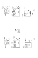
本実施例では、電力を送電する送電装置と電力を受電する受電装置を有する無線電力伝送システムについて説明する。本実施例における無線電力伝送システムの一例を図1に示す。図1は本実施例の無線電力伝送システムの一例であり、3つの送電装置TX1〜3(101〜103)と、5つの受電装置RX1〜5(104〜108)からなる。TX1〜3(101〜103)の夫々は、無線を用いて送電を行う無線電力伝送装置である。受電装置RX1〜5(104〜108)の夫々は、携帯電話、ディジタルカメラ、タブレット端末、ホームビデオ等の機器であり、送電装置から電池の充電、または動作のための電力を無線を用いて受電する無線電力伝送装置である。
Example 1
In this embodiment, a wireless power transmission system including a power transmission device that transmits power and a power reception device that receives power will be described. An example of the wireless power transmission system in the present embodiment is shown in FIG. FIG. 1 shows an example of a wireless power transmission system according to this embodiment, which includes three power transmission devices TX1 to TX3 (101 to 103) and five power receiving devices RX1 to RX5 (104 to 108). Each of TX1 to TX3 (101 to 103) is a wireless power transmission apparatus that performs power transmission using radio. Each of the power receiving devices RX1 to RX5 (104 to 108) is a device such as a mobile phone, a digital camera, a tablet terminal, a home video, etc., and receives power from the power transmission device for charging a battery or operating wirelessly. A wireless power transmission device.
なお、図1(a)において、受電装置RX1(104)は、これから無線電力伝送により充電を開始しようとしている装置である。受電装置RX2(105)は送電装置TX1(103)上にあり、は送電装置TX1(101)と無線電力伝送を行っている。受電装置RX3は送電装置TX3(103)上にあり、送電装置TX3(103)と無線電力伝送を行っている。受電装置RX4、5は、送電装置TX2(102)上にあり、夫々は送電装置TX2(102)と無線電力伝送を行っている。 In FIG. 1A, a power receiving device RX1 (104) is a device that is about to start charging by wireless power transmission. The power receiving device RX2 (105) is on the power transmission device TX1 (103), and performs wireless power transmission with the power transmission device TX1 (101). The power receiving device RX3 is on the power transmission device TX3 (103) and performs wireless power transmission with the power transmission device TX3 (103). The power receiving devices RX4 and 5 are on the power transmitting device TX2 (102), and each performs wireless power transmission with the power transmitting device TX2 (102).
続いて、本実施例における送電装置及び受電装置の構成を図2に示す。21は送電装置、22は受電装置である。送電装置21は、電力線213から供給される電力を送電回路211で高周波化し、送電アンテナ212から無線により電力を送電する。ここで送電回路211は受電装置が送電に適した位置に配置されたことをインピーダンス変化等で検出する受電装置検出部2110を有している。また、送電回路211は、送電している電力の総和(総送電電力量)を検出する総送電量検出部2111を有している。送電回路211は、後述するCPU2150の制御に基づき複数の受電装置に同時に送電を行うことができる。また、214は、無線電力伝送に係る状況をユーザに通知する通知部である。図1においては、通知部214は、LEDランプ等の発光により無線電力伝送に係る状況をユーザに通知する。通知部214が通知する無線電力伝送に係る通知は、更なる受電装置を受け入れて送電を開始することができることを示す通知(以後、通知Aと称する)である。また、通知部214が通知する無線電力伝送に係る通知は、更なる受電装置を受け入れることができず、更なる装置に対しては送電を開始することができないことを示す通知である(以後、通知Bと称する)。
Then, the structure of the power transmission apparatus and power receiving apparatus in a present Example is shown in FIG.
本実施例において、通知部214は通知A、Bを異なる色の発光でそれぞれを通知するものとする。また、通知部214は通知A、Bを異なる点滅パターンの発光でそれぞれを通知してもよい。例えば、送電可能であることを示す通知(通知A)は「点灯」で示し、送電不可能であることを示す通知(通知B)は「消灯」として通知するようにしてよい。なお、通知部214は、本実施形態において、LEDランプ等の発光により無線電力伝送に係る状況をユーザに通知する構成としたが、ディスプレイ等による画像やメッセージの表示で通知を行うように構成してよい。また、スピーカによる音声出力による通知でもよい。また、振動発生装置等による振動を用いて通知を行っても良い。
In the present embodiment, the
続いて、2150は、CPU(Central Processing Unit)である。2151は、RAM(Random Access Memory)である。2152は、ROM(Read Only Memory)である。CPU2150は、ROM2152に保持している制御プログラムをRAM2151に読み込み、実行することで装置全体を制御する。2153は操作部であり、ユーザが各種入力等を行い、装置を操作するための操作部である。
Subsequently, 2150 is a CPU (Central Processing Unit).
続いて、受電装置の構成について説明を行う。受電装置22は受電アンテナ222から受電された無線電力を整流し、定電圧回路等の電力変換を行う受電回路221を介して電力線223に電力を供給する。なお、受電した電力は電力線223を介して不図示のバッテリ等の2次電源に供給されてもよいし、電源として装置のハードウェアに直接供給されてもよい。続いて、2280は、CPUである。2281は、RAMである。2282は、ROMである。CPU2280は、ROM2282に保持している制御プログラムをRAM2281に読み込み、実行することで装置全体を制御する。
Next, the configuration of the power receiving device will be described. The
以上の構成を有する本実施例における無線電力伝送システムの動作について説明を行う。本実施例における無線電力伝送システムにおける送電装置は、複数の受電装置に対して送電を行うことができる。本実施例の受電装置は5Wの電力を受電することで適切に受電動作が行うことができる。受電動作とは、受電装置のバッテリの充電や、給電された電力により動作することである。また、本実施例の送電装置は10Wまで送電を行うことが可能である。したがって、2台の受電装置には同時に送電を行うことができるが、3台の受電装置には同時に適切に送電を行うこができなくなる。 The operation of the wireless power transmission system in the present embodiment having the above configuration will be described. The power transmission device in the wireless power transmission system according to the present embodiment can transmit power to a plurality of power reception devices. The power receiving device of this embodiment can appropriately perform a power receiving operation by receiving 5 W of power. The power receiving operation is to operate by charging the battery of the power receiving apparatus or by the supplied power. Moreover, the power transmission apparatus of a present Example can transmit power to 10W. Accordingly, power can be transmitted to the two power receiving apparatuses at the same time, but power cannot be appropriately transmitted to the three power receiving apparatuses at the same time.
本実施例の無線電力伝送システムにおける送電装置は、第1受電装置に送電中に、第2受電装置に対して送電を行うことができることを通知する。また、第1受電装置に送電中に、第2受電装置に検出して、第1受電装置と第2受電装置に同時に送電を開始したことに応じて、第3受電装置には送電を行うことができないことを通知する。 The power transmission device in the wireless power transmission system of the present embodiment notifies the second power receiving device that power can be transmitted during power transmission to the first power receiving device. In addition, during power transmission to the first power receiving device, detection is performed by the second power receiving device, and power is transmitted to the third power receiving device in response to simultaneous start of power transmission to the first power receiving device and the second power receiving device. Notify that you cannot.
図1(a)においては、各送電装置TX1〜TX3には例えばLEDランプ等の発光体が具備されており、該発光体の発光により新たな受電装置に対して送電が行えるか否かの通知を含む無線伝送に係る通知を行う。図1(a)において、送電装置TX1(101)は一台の受電装置RX2(105)にしか送電を行っておらず、送電可能な電力がさらなる受電装置への送電が可能なほど十分であるため、新たな受電装置に対する送電が可能なことの通知を行っている。また、送電装置TX2(102)は、受電装置RX4(107)と受電装置RX5(108)との複数台に送電を行っている。送電装置TX2(102)は、送電可能な電力が受電装置に送電を行うのに十分ではないため、新たな受電装置に対して送電が可能ではないことを示す通知を行い、ユーザに更に受電装置を送電面上に置くことを抑制するための警告を発している。また、送電装置TX3(103)は一台の受電装置RX3(106)にしか送電を行っておらず、送電可能な電力がさらなる受電装置への送電が可能なほど十分であるため、新たな受電装置に対する送電が可能なことの通知を行っている。 In FIG. 1A, each of the power transmission devices TX1 to TX3 is provided with a light emitter such as an LED lamp, for example, and notification of whether or not power can be transmitted to a new power receiving device by light emission of the light emitter. Notification related to wireless transmission including In FIG. 1A, the power transmission device TX1 (101) transmits power to only one power reception device RX2 (105), and the power that can be transmitted is sufficient to allow power transmission to a further power reception device. Therefore, notification that power transmission to the new power receiving apparatus is possible is performed. The power transmission device TX2 (102) transmits power to a plurality of power reception devices RX4 (107) and RX5 (108). The power transmitting device TX2 (102) notifies the new power receiving device that power transmission is not possible because the power that can be transmitted is not sufficient to transmit power to the power receiving device, and further notifies the user of the power receiving device. Is issued to suppress placing on the power transmission surface. In addition, the power transmission device TX3 (103) transmits power to only one power reception device RX3 (106), and the power that can be transmitted is sufficient to allow power transmission to a further power reception device. Notification that power transmission to the device is possible.
ここで、新たに充電を希望する受電装置RX1(104)のユーザは、上述した各送電装置の通知により、何れの送電装置を用いれば良いかを判定することができる。例えば、図1(a)において、RX1(104)のユーザは、RX1(104)と一番距離が近い送電装置のTX2(102)が新たな受電装置に対しては送電が行えないことを認識することができる。また、RX1(104)のユーザは、TX2(102)が送電不可能で他の送電装置を選択すべきであることを、送電装置TX2(102)に受電装置を置いてしまう前に容易に認識できる。続いて、受電装置RX1(104)のユーザは、送電装置TX2(102)を利用ができない状態を認識し、送電装置TX3(103)に受電装置RX1(104)を置き充電を開始したとする。図1(b)は、送電装置TX3(103)に受電装置RX1(104)を置き充電を開始した後のシステム構成図である。送電装置TX3(103)は、受電装置RX1(104)に送電を開始する場合、送電可能な電力はこれ以上台数が増える同時送電が行えないと判定し、該判定結果に応じた通知を行っている。 Here, the user of the power receiving device RX1 (104) who wishes to newly charge can determine which power transmission device should be used based on the notification of each power transmission device described above. For example, in FIG. 1A, the user of RX1 (104) recognizes that TX2 (102) of the power transmission device closest to RX1 (104) cannot transmit power to the new power receiving device. can do. Further, the user of RX1 (104) easily recognizes that TX2 (102) cannot transmit power and should select another power transmission device before placing the power receiving device on power transmission device TX2 (102). it can. Subsequently, it is assumed that the user of the power receiving device RX1 (104) recognizes a state where the power transmitting device TX2 (102) cannot be used, and places the power receiving device RX1 (104) in the power transmitting device TX3 (103) and starts charging. FIG. 1B is a system configuration diagram after charging is started by placing the power receiving device RX1 (104) in the power transmitting device TX3 (103). When starting to transmit power to the power receiving device RX1 (104), the power transmitting device TX3 (103) determines that the power that can be transmitted cannot be transmitted at the same time when the number of power transmissions further increases, and performs notification according to the determination result. Yes.
このように、本実施例における送電装置は、受電装置に送電を開始するタイミングで、別の受電装置に対して送電可能かどうかを判定し、該判定結果を通知する。したがって、ユーザは該別の受電装置を送電装置に置く前に該送電装置が利用可能かを判定することができるので、送電装置に受電装置を置いているにも関わらず充電が実行されないという不具合を低減できる。また、例えば、送電装置が複数台近くにある場合に、ユーザはどの送電装置を用いて受電すればよいかを容易に選択することができる。 As described above, the power transmission device according to the present embodiment determines whether or not power can be transmitted to another power receiving device at the timing of starting power transmission to the power receiving device, and notifies the determination result. Therefore, since the user can determine whether the power transmission device can be used before placing the other power reception device on the power transmission device, charging is not performed even though the power reception device is placed on the power transmission device. Can be reduced. Further, for example, when there are a plurality of power transmission devices, the user can easily select which power transmission device should be used to receive power.
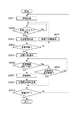
本実施例における送電装置の動作を図3に示すフローチャートを用いて説明を行う。なお、図3のフローチャートは送電装置のCPU2150が制御プログラムを実行することにより装置全体を制御することにより実現される。まず、送電装置の通知部214は、電源が投入された直後に送電が可能であることを示す通知(通知A)を行う(S301)。続いて、受電装置検出部2110は、送電装置上に置かれた受電装置の検出処理(S302)を開始する。なお、受電装置検出部2110は、送電装置上に置かれなくても、送電装置から無線電力伝送可能な範囲に存在する受電装置を検出するようにしてもよい。本実施例における検出処理の一例は、電磁波を放出しているアンテナ21に近接した受電装置がいることの影響で送電装置内部の回路に発生する電力に基づいて、送電回路211付近のインピーダンスの変化を検出する処理である。検出処理では、該インピーダンスの変化を検出することで、受電装置の検出および受電装置の位置を検出する。
The operation of the power transmission device in this embodiment will be described with reference to the flowchart shown in FIG. Note that the flowchart of FIG. 3 is realized by the
検出処理により、受電装置が新たに検出されるとCPU2150は、検出した受電装置と異なる他の受電装置に送電中であるかを判定する。CPU2150は、他の受電装置に送電中であると判定した場合(S303のYes)、送電回路211を制御し、送電を中止する(S304)。電源投入後に初めて受電装置を検出した場合には他の受電装置に送電中ではないため、S305に処理を進める。受電装置検出部2110は、インピーダンス変化量に基づいて、新たに検出された受電装置の位置を判定する。CPU2150は、新たに検出された受電装置の位置が、送電を行う上で適正な位置にある場合(S305のYes)、送電回路211を制御し、送電を開始する(S306)。ここで、送電を行う上で適正な位置とは、送電アンテナ212と受電アンテナ222との距離(位置関係)に基づいて規定され、送電効率が所定の値(ここでは70%とする)以上となる範囲である。また、S306による送電は、S303により送電中であったと判定された場合、送電中であった他の受電装置とS302で検出した新たに検出した受電装置との全ての受電装置に送電を開始する。
When a new power receiving device is detected by the detection process, the
一方、S305において、受電装置検出部2110が新たに検出した受電装置が適正な位置に存在しないと判定した場合は、送電を停止した状態のままで送電を開始しない。送電装置と受電装置とが適正な位置で送電を行わないと送電効率が悪くなり、発熱が生じる恐れがあるためである。新たに検出された受電装置が送電における適正位置に存在しない場合、適正位置に配置することをユーザに促す通知を通知部214が行っても良い。なお、受電装置側に発熱が生じないようなインピーダンス制御を行う回路が設けられている無線電力伝送システムである場合は、新たな受電装置を検出した際の送電の中止を行わないようにすることもできる。即ち、インピーダンス制御を行う第1の受電装置に送電中に第2の受電装置を検出した場合、第1の受電装置に対する送電を継続するようにしてもよい。このような無線電力伝送システムの場合、S304の処理は省略する。
On the other hand, in S305, when it is determined that the power receiving device newly detected by the power receiving
受電装置検出部2110が、新たに検出された受電装置が送電の適正位置にいることを検出した場合(S305のYes)、CPU2150は、送電回路211を制御し、送電を開始する(S306)。S306における送電は、受電装置1台につき予め定められている電力値により行われるものとする(上述の説明では5W)。また、先に置かれていた受電装置に対する電力はS306において送電を停止する前に送電していた電力と変わらないものとする。また、S306において送電する電力は、検出した受電装置夫々で均等に割り当てられるようにしてもよい。
When the power receiving
ここで総送電量検出部2111は、送電している全ての受電装置への送電電力の総和を検出する(S307)。CPU2150は、送電装置の送電可能な上限電力(上述の説明では10W)と上記送電電力の総和を比較する。CPU2150は、上限電力と送電電力の総和との差分(送電可能な電力)が、さらなる受電装置へ送電可能であるか否かを判定する(S308)。ここで、本実施例におけるS308の判定は、受電装置1台に送電するのに十分である予め定めた電力の閾値を送電装置は保持しておく。本実施例においては、受電装置は5Wの電力を受電するので、上述の電力の閾値は5Wとする。そして、送電装置の送電可能な電力がこの保持している閾値を上回る場合は、さらなる受電装置へ送電可能であると判定する。一方、送電装置の送電可能な電力がこの保持している閾値を下回る場合は、さらなる受電装置へ送電可能でないと判定する。なお、S308の判定は、送電電力の総和に基づいて行っているが送電可能な受電装置の台数を予め定めておき、同時送電を行っている受電装置が予め定めた台数に達したかを判定するようにしてもよい。本実施例においては、各受電装置は5Wの電力を受電し、送電装置の上限電力は10Wである。したがって、送電装置は2台の受電装置に同時に送電可能である。この場合、送電装置は、送電を行っている受電装置の台数をカウントし、2台の受電装置に送電を開始したことの検出をS308における判定基準としてよい。
Here, the total power transmission
S308の判定においてさらなる受電装置へ送電可能ではないと判定した場合、通知部214は、送電が可能ではないことを示す通知(通知B)を行う。なお、S308の判定においてさらなる受電装置へ送電可能ではないと判定した場合、定期的にS308における判定を行う構成とする。受電装置がバッテリ等の2次電池に受電した電力を充電する装置である場合、送電中の受電装置の充電量に応じて必要な電力は徐々に減少するためS308の判定結果も変わるためである。
If it is determined in step S308 that power cannot be transmitted to a further power receiving apparatus, the
そして、送電装置のCPU2150は、装置の電源がOFFされない限り(S310のNo)上述の処理を繰り返す。ここで、送電装置のS310はさらなる受電装置の追加送電可能であるかの判断(S308)の後になっているが電源OFFの操作の検出ははどのタイミングで行われてもよい。送電装置の電源OFF操作の検出に応じて本処理を終了する(S310のYes)。
Then,
以上説明したように、本実施例によれば、送電装置が、第1受電装置に送電を開始するタイミングで、別の第2受電装置に対して送電可能かどうかを判定し、該判定結果を通知する。したがって、ユーザは該第2受電装置を送電装置に置く前に該送電装置が利用可能かを判定することができるので、送電装置に受電装置を置いているにも関わらず充電が実行されないという事態を低減できる。また、例えば、送電装置が複数台近くにある場合に、ユーザはどの送電装置を用いて受電すればよいかを容易に選択することができる。 As described above, according to the present embodiment, it is determined whether or not power transmission is possible to another second power receiving device at the timing when the power transmitting device starts power transmission to the first power receiving device, and the determination result is obtained. Notice. Therefore, since the user can determine whether the power transmission device can be used before placing the second power receiving device on the power transmission device, charging is not performed even though the power reception device is placed on the power transmission device. Can be reduced. Further, for example, when there are a plurality of power transmission devices, the user can easily select which power transmission device should be used to receive power.
(実施例2)
実施例2では、送電装置が通信により、受電装置から要求する電力値を受信し、該電力値を送電可能であるか否かを示す通知を行う。
(Example 2)
In the second embodiment, the power transmission device receives a power value requested from the power receiving device through communication, and notifies whether the power value can be transmitted.
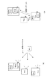
図4(a)は本実施例の第2の実施例の無線電力伝送システムの構成図である。3つの送電装置TX1〜3と、4つの受電装置RX1〜4からなる。なお、図4(a)において、受電装置RX1は、これから無線電力伝送により充電を開始しようとしている装置である。受電装置RX2とRX4は送電装置TX1上にあり、は送電装置TX1と無線電力伝送を行っている。受電装置RX3は送電装置TX3上にあり、送電装置TX3と無線電力伝送を行っている。 FIG. 4A is a configuration diagram of the wireless power transmission system according to the second embodiment of the present embodiment. It consists of three power transmission devices TX1 to TX3 and four power reception devices RX1 to RX4. In FIG. 4A, the power receiving device RX1 is a device that is about to start charging by wireless power transmission. The power receiving devices RX2 and RX4 are on the power transmitting device TX1, and are performing wireless power transmission with the power transmitting device TX1. The power receiving device RX3 is on the power transmission device TX3 and performs wireless power transmission with the power transmission device TX3.
第2の実施例の無線電力伝送装置の構成を図5に示す。なお、実施例1において説明した図2と同一な構成については同じ符号を付し、その説明を省略する。本実施例における送電装置の構成が実施例1と異なる点は、無線通信部216、アンテナ217、通信線218を更に有することにより、無線電力伝送を行う電磁波とは異なる周波数を用いたアウトバンド通信が可能になっていることである。また、本実施例における受電装置も、無線通信部225、通信線227、アンテナ226を有し送電装置と無線通信を行うことが可能である。
The configuration of the wireless power transmission apparatus of the second embodiment is shown in FIG. In addition, the same code | symbol is attached | subjected about the structure same as FIG. 2 demonstrated in Example 1, and the description is abbreviate | omitted. The configuration of the power transmission apparatus in the present embodiment is different from that of the first embodiment in that it further includes a
無線通信部216、225はブルートゥース、無線LAN(IEEE802.11シリーズ)、ワイヤレスUSB、NFC(Near field Communication)等の無線通信を行うためのチップである。通信線218,227は通信データを伝送するための信号線である。アンテナ217、226は、通信用の電磁波を放射または受信するためのアンテナである。
The
続いて、図7は通信範囲701と送電装置21の適正な効率で送電可能な適正送電範囲702を示している。通常ブルートゥース、無線LAN、ワイヤレスUSB等の無線通信範囲は数m以上である。即ち通信可能範囲701の数m以内に複数の送電装置TX1からTX3が存在した場合、受電装置RX1の送電リクエスト(電力要求)を夫々が受信することが可能である。このように、無線通信可能な距離の方が、無線電力伝送が可能な距離より大きいものとして説明を行う。 図4(a)において、受電装置RX1は必要な電力を含む送電リクエスト(電力要求)を送電装置TX1〜TX3に送信する。ここで送電装置TX1はすでに受電装置RX2とRX4に送電をしており、送電リクエスト中に含まれる電力を送電できないため、送電不可能通知を行っている。送電装置TX2上には何れの受電装置に対しても送電を行っておらず、送電リクエストを送信した受電装置RX1に送電可能であるため、送電可能通知を行っている。また、送電装置TX3は受電装置RX3に送電中にも関わらず、送電容量に余力があり、送電リクエストを送信した受電装置RX1にも送電可能であるため、送電可能通知を行っている。
Next, FIG. 7 shows a communication range 701 and a proper power transmission range 702 in which power can be transmitted with appropriate efficiency of the
受電装置RX1への受電を希望するユーザは送電可能通知を行っている送電装置が受電装置RX1の送電リクエストに含まれる電力を送電可能であることを確認できる。図4においては送電装置TX2、またはTX3と受電装置RX1は無線電力伝送を行うことが可能である。さらに本実施例では図4(B)のように、受電装置RX1のユーザは、送電装置TX3を選択して受電装置RX1を送電装置TX3上に置いた場合、受電装置RX1に送電を開始した送電装置TX3は、送電可能通知を中止する。そして、次の受電装置の送電リクエストの受信を待機する。 A user who desires to receive power to the power receiving apparatus RX1 can confirm that the power transmitting apparatus that has made a power transmission notification can transmit the power included in the power transmission request of the power receiving apparatus RX1. In FIG. 4, the power transmission device TX2 or TX3 and the power reception device RX1 can perform wireless power transmission. Furthermore, in this embodiment, as illustrated in FIG. 4B, when the user of the power receiving device RX1 selects the power transmitting device TX3 and places the power receiving device RX1 on the power transmitting device TX3, power transmission that starts power transmission to the power receiving device RX1. The device TX3 cancels the notification that power transmission is possible. And it waits for reception of the power transmission request of the next power receiving apparatus.
一方、送電装置TX2は送電可能通知を行ったにも関わらず受電装置RX1を検出することなく、送電可能通知を通知し続けてしまう恐れがある。そこで、本実施例においては、送電を開始した送電装置または受電を開始した受電装置が、周囲の他の送電装置に対して送受電を開始したことを通知する。そして、受電装置の送電リクエストの受信し、送電可能通知を行った送電装置は該送受電を開始したことの通知の受信に応じて、送電可能通知を中止する。図4(b)の例では、送電を開始した送電装置TX3は、送電装置TX2および送電装置TX1に対し、送電開始通知を無線通信部216を介して送信を行う。送電開始通知を受信した送電装置TX2は送電可能通知を中止する。また、送電開始通知を受信した送電装置TX1は送電不可能通知を中止する。なお、送電開始通知には、送電を開始した送電装置の識別子や受電を開始した受電装置の識別子を含めるものとする。
On the other hand, the power transmission device TX2 may continue to notify the power transmission possible notification without detecting the power receiving device RX1 even though the power transmission possible notification is performed. Therefore, in this embodiment, the power transmission device that has started power transmission or the power reception device that has started power reception notifies other surrounding power transmission devices that power transmission / reception has started. Then, the power transmission device that has received the power transmission request of the power reception device and has made a power transmission enable notification stops the power transmission enable notification in response to reception of the notification that the power transmission / reception has started. In the example of FIG. 4B, the power transmission device TX3 that has started power transmission transmits a power transmission start notification to the power transmission device TX2 and the power transmission device TX1 via the
なお、通知部214をLEDランプ等の発光体により構成する場合、送電可能通知をランプの点灯とし、送電不可能通知をランプの消灯とすることができる。この場合、受電装置からの送電リクエストにより、送電可能ではないと判定した場合は、ランプは消灯したままである。また、他の装置から送電開始通知を受信した場合も、ランプを消灯したままにすることができる。
Note that when the
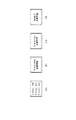
本実施例における送電装置の動作を図6に示すフローチャートを用いて説明を行う。なお、図6のフローチャートは送電装置のCPU2150が制御プログラムを実行することにより装置全体を制御することにより実現される。送電装置のCPU2150は、処理を開始すると受電装置からの送電リクエストの受信を待機する待機状態をとなる(S601)。なお、待機状態では、通知部214による通知を行わないようにする。続いて、CPU2150は、無線通信部216を介して受電装置から送電リクエストを受信したかを判定する(S602)。送電リクエストを受信すると、送電装置は総送電量検出部2111を用いて、送電している全ての受電装置への送電電力の総和を検出する(S603)。そして、CPU2150は、受信した送電リクエストに含まれる受電装置が要求する電力値を送電可能か否かを判定する(S604)。S604の判定において送電可能であると判定した場合、通知部214は、送電が可能であることを示す通知を行う(S605)。また、S604の判定において送電可能ではないと判定した場合、通知部214は、送電が可能ではないことを示す通知を行う(S611)。そして、次の送電リクエストを待つためにS601に戻る。
The operation of the power transmission device in this embodiment will be described with reference to the flowchart shown in FIG. Note that the flowchart of FIG. 6 is realized by the
送電可能通知を通知した場合、受電装置検出部2110は、受電装置が送電に適した範囲、すなわち図7の702の範囲に入っているかを確認する(S606)。CPU2150は、受電装置が送電を行う上で適正な位置にあれば送電回路211を制御し送電を開始する(S607)。送電を開始すると無線通信部216は、送電開始通知を周囲の他の送電装置に送信する(S608)。一方、受電装置が送電の適正位置にない場合(S606のNo)、無線通信部216は、送電開始通知を受信したかを判定する(S609)。他の送電装置からの送電開始通知を受信した場合(S609のYes)には電源がOFFされない限り(S610のNo)待機状態に戻り、送電可能通知を中止する(S601)。なお、S611の送電不可能通知がランプの消灯状態により通知する場合ではない場合には、送電不可能通知も同様に中止する。
When notifying that the power transmission is possible, the power receiving
以上説明したように、本実施例によれば、複数台の受電装置に送電可能である送電装置が、受電装置から通信により要求された電力に応じて該受電装置に対して送電可能かどうかを判定し、該判定結果を通知する。したがって、無線電力伝送可能な範囲より広い通信可能範囲を有する通信を用いることによりユーザは受電装置を送電装置に置く前に該送電装置が利用可能かを判定することができる。また、無線電力伝送可能な範囲より広い通信可能範囲を有する通信を用いることにより、無線電力伝送に係る通知は受電装置が送電装置と無線電力伝送が可能な距離となる前に通知することができる。これにより、送電装置に受電装置を置いているにも関わらず充電が実行されないという事態を低減できる。また、例えば、送電装置が複数台近くにある場合に、ユーザはどの送電装置を用いて受電すればよいかを容易に選択することができる。 As described above, according to the present embodiment, whether or not a power transmission device capable of transmitting power to a plurality of power reception devices can transmit power to the power reception device according to power requested by communication from the power reception device. Determine and notify the determination result. Therefore, the user can determine whether or not the power transmission device can be used before placing the power reception device on the power transmission device by using communication having a communication range wider than the wireless power transmission range. In addition, by using communication having a communication range wider than the range in which wireless power transmission is possible, notification regarding wireless power transmission can be notified before the power receiving device reaches a distance that allows wireless power transmission from the power transmission device. . As a result, it is possible to reduce a situation in which charging is not performed even though the power receiving device is placed in the power transmitting device. Further, for example, when there are a plurality of power transmission devices, the user can easily select which power transmission device should be used to receive power.
次に、本実施例において第1受電装置からの送電リクエストに基づく通知を行っている場合に第1受電装置と異なる第2受電装置から送電リクエストを受信した場合の送電装置の無線電力伝送に係る状態の通知の一例について説明を行う。この例では、通知部214は、受信した複数の受動装置からの送電リクエスト夫々に送電が可能である場合は、送電可能であることを示す通知(通知A)を通知する。また、通知部214は、受信した複数の受動装置からの送電リクエスト夫々に送電が可能ではない場合、送電が可能ではないことを示す通知(通知B)を通知する。また、受信した複数の受電装置の送電リクエストの一方には送電可能であり、他方には送電可能ではない場合、該状態を示す通知(以下、通知Cと称する)を通知する。なお、通知部214をLEDランプ等の発光体により構成する場合、送電可能通知をランプの点灯とし、送電不可能通知をランプの消灯とし、上述の通知Cは、ランプの点滅として通知することができる。
Next, in the present embodiment, when a notification based on a power transmission request from the first power receiving device is performed, wireless power transmission of the power transmitting device when receiving a power transmission request from a second power receiving device different from the first power receiving device An example of status notification will be described. In this example, the
この例における送電装置の動作について説明する。送電装置は、第1受電装置からの送電リクエストに基づく送電可否を通知している際に、第2受電装置から送電リクエストを受信した場合、第2受電装置からの要求に基づく送電可否の判定結果が、通知中の内容と同一であるかを判定する。例えば、送電装置が10Wの送電可能な電力がある場合に第1受電装置から5Wの電力を要求する送電リクエストを受信したとする。この場合、送電装置は、第1受電装置に対して送電可能あるので通知Aを通知している。そして、送電装置は、通知Aを通知中に第2受電装置から10Wの電力を要求する送電リクエストを受信したとする。送電装置は、第2受電装置から10Wの電力の要求に対して送電を行うことができるか否かの判定が、第1受電装置からの要求に対する判定と同一かどうかを判定する。この場合、送電装置が10Wの送電可能な電力があるため、第2受電装置から要求された10Wの電力を送電できる。したがって、送電装置は第1受電装置からの要求に対する判定結果と第2受電装置からの要求に対する送電可否の判定結果が同一であると判定する。送電装置は、第2受電装置から要求された電力の送電可否の判定結果が、第1受電装置からの要求された電力の送電可否の結果と同一である場合は、第1受電装置からの送電リクエストに基づく通知Aまたは通知Bを継続する。上述の例では、送電装置は第2受電装置から要求された電力の送電可否の判定結果が、第1受電装置からの要求された電力の送電可否の結果と同一であるため、通知Aの通知を継続する。 The operation of the power transmission device in this example will be described. When the power transmission device has notified the power transmission request based on the power transmission request from the first power receiving device and receives the power transmission request from the second power receiving device, the power transmission permission determination result based on the request from the second power receiving device Is the same as the content being notified. For example, it is assumed that the power transmission device receives a power transmission request for requesting 5 W of power from the first power receiving device when there is power that can be transmitted of 10 W. In this case, since the power transmission device can transmit power to the first power receiving device, the power transmission device notifies the notification A. Then, it is assumed that the power transmission apparatus receives a power transmission request for requesting 10 W of power from the second power receiving apparatus during notification A. The power transmission device determines whether or not the determination as to whether or not the second power reception device can perform power transmission in response to a request for 10 W power is the same as the determination regarding the request from the first power reception device. In this case, since the power transmission device has 10 W of power that can be transmitted, the power of 10 W requested from the second power reception device can be transmitted. Therefore, the power transmission device determines that the determination result with respect to the request from the first power receiving device is the same as the determination result of whether power transmission is possible with respect to the request from the second power receiving device. The power transmission device transmits power from the first power receiving device when the determination result of power transmission requested from the second power receiving device is the same as the result of power transmission requested from the first power receiving device. Continue notification A or notification B based on the request. In the above-described example, since the determination result of whether or not the power requested from the second power receiving device can be transmitted is the same as the result of whether or not the power requested from the first power receiving device is transmitted, the notification of notification A Continue.
また、第1受電装置および第2受電装置から要求に対して夫々送電可能であり、送電装置が通知Aを通知している際に第1受電装置または第2受電装置を自装置の送電可能範囲に検出した場合を説明する。この場合、送電装置は、検出した装置への送電開始後の残存電力が他方の要求する電力を満たすかを判定する。そして、送電開始後に他方の要求に基づく通知を行うようにして良い。上述の例で説明を行うと送電装置は、第1受電装置および第2受電装置からの送電リクエストに基づいて通知Aを通知している際に、第1受電装置を送電可能範囲において検出し送電を開始したとする。第1受電装置は5Wを要求していたため、第1受電装置への送電開始後の送電装置の残存電力は5Wである(送電可能な電力10Wから第1受電装置が要求した5Wを引いた値)。送電装置は、残存電力5Wでは、第2受電装置が要求した電力(10W)を送電できないため、通知Bの通知を開始する。また、第1受電装置および第2受電装置が受電を開始したことを示す送電開始通知を夫々受信した場合、上述の待機状態(S601)に戻る構成としてよい。 Further, the first power receiving device and the second power receiving device can each transmit power in response to the request, and when the power transmitting device notifies the notification A, the first power receiving device or the second power receiving device can transmit power to the own device. The case where it is detected will be described. In this case, the power transmission device determines whether the remaining power after the start of power transmission to the detected device satisfies the other required power. Then, notification based on the other request may be performed after the start of power transmission. In the example described above, the power transmission device detects the first power reception device in the power transmission possible range when notifying the notification A based on the power transmission requests from the first power reception device and the second power reception device. Is started. Since the first power receiving apparatus has requested 5 W, the remaining power of the power transmitting apparatus after the start of power transmission to the first power receiving apparatus is 5 W (a value obtained by subtracting 5 W requested by the first power receiving apparatus from 10 W of power that can be transmitted) ). Since the power transmission device cannot transmit the power (10 W) requested by the second power receiving device with the remaining power of 5 W, the power transmission device starts notification B. In addition, when each of the first power receiving device and the second power receiving device receives a power transmission start notification indicating that power reception has started, it may be configured to return to the standby state (S601).
一方、第1受電装置からの送電リクエストに基づく通知を行っている際の第2受電装置から要求された電力の送電可否の判定結果が、第1受電装置からの要求された電力の送電可否の結果と同一でない場合、通知Cの通知を開始する。この場合の例として、送電装置は、送電装置が10Wの送電可能な電力がある場合に第1受電装置から5Wの電力を要求する送電リクエストを受信したとする。送電装置は、第1受電装置に5W送電することができるため第1受電装置からの要求に応じて通知Aを通知している場合に、第2受電装置から15Wの送電を要求されたとする。送電装置は、送電可能な電力10Wであるため、第2受電装置から要求された15Wは送電できないと判定する。また、通知中であった第1受電装置からの要求に対する送電可否の判定結果と受信した第2受電装置からの要求に対する送電可否の判定結果が同一でないため、通知Cの通知を開始する。通知Cの通知を終了するタイミングは、通知Cの通知を行っている際に第1受電装置または第2受電装置の何れかに対応する送電開始通知を受信した場合、他方の送電リクエストに基づく送電可否の判定結果に対応する通知に変更する。 On the other hand, when the notification based on the power transmission request from the first power receiving device is performed, the determination result of whether or not the power requested from the second power receiving device can be transmitted indicates whether the power requested from the first power receiving device can be transmitted. If it is not the same as the result, notification C is started. As an example of this case, it is assumed that the power transmission apparatus receives a power transmission request for requesting 5 W of power from the first power receiving apparatus when the power transmission apparatus has 10 W of power that can be transmitted. Since the power transmission device can transmit 5 W to the first power receiving device, when the notification A is notified in response to a request from the first power receiving device, it is assumed that 15 W power transmission is requested from the second power receiving device. Since the power transmission device has a power of 10 W that can be transmitted, it is determined that 15 W requested from the second power receiving device cannot be transmitted. In addition, since the determination result of whether or not power transmission with respect to the request from the first power receiving apparatus that was being notified is not the same as the determination result of whether or not power transmission is possible with respect to the received request from the second power receiving apparatus, notification of notification C is started. When the notification C is ended, when the notification C is being notified and the power transmission start notification corresponding to either the first power receiving device or the second power receiving device is received, the power transmission based on the other power transmission request is performed. Change to a notification corresponding to the determination result.
このように構成することで複数の受電装置が存在する場合、各受電装置から送電リクエストまたは他の送電装置から送電開始通知を受信するたびに、通知の変更、通知の中止が行われなくなり、ユーザの混乱を招くことが低減される。 With this configuration, when there are a plurality of power receiving devices, every time a power transmission request is received from each power receiving device or a power transmission start notification is received from another power transmitting device, the notification is not changed and the notification is not stopped. Confusion is reduced.
なお、本実施例において第1受電装置からの送電リクエストに基づく通知を行っている場合に第1受電装置と異なる第2受電装置から送電リクエストを受信した場合の送電装置の無線電力伝送に係る状態の通知の他の一例について説明を行う。上述の例では、第1受電装置からの要求と第2受電装置からの要求との夫々を、送電装置は個別に送電可能であるかを判定し、夫々の判定結果が同一か否かに応じて通知を行う例を示した。本例では、第1受電装置からの送電リクエストに基づく通知を行っている場合に第1受電装置と異なる第2受電装置から送電リクエストを受信した場合、第1受電装置と第2受電装置を共に送電できるかの判定を行う。そして、送電装置は、第1受電装置と第2受電装置を共に送電できるかの判定に応じて通知を行う。 In the present embodiment, when notification based on a power transmission request from the first power receiving device is performed, a state relating to wireless power transmission of the power transmitting device when a power transmission request is received from a second power receiving device different from the first power receiving device Another example of the notification will be described. In the above-described example, the request from the first power receiving device and the request from the second power receiving device are determined to determine whether the power transmitting device can transmit power individually, and depending on whether the determination results are the same. An example of notification is shown. In this example, when a notification is made based on a power transmission request from the first power receiving device, when a power transmission request is received from a second power receiving device different from the first power receiving device, both the first power receiving device and the second power receiving device are used. Determine whether power can be transmitted. And a power transmission apparatus notifies according to determination of whether a 1st power receiving apparatus and a 2nd power receiving apparatus can be transmitted together.
本例の通知方法を具体例を示して説明を行う。例えば、送電装置が15Wの送電可能な電力がある場合に第1受電装置から5Wの電力を要求する送電リクエストを受信したとする。この場合、送電装置は、第1受電装置に対して送電可能あるので通知Aを通知している。そして、送電装置は、通知Aを通知中に第2受電装置から10Wの電力を要求する送電リクエストを受信したとする。送電装置は、15Wの送電可能な電力あるため、第1の受電装置から要求された5Wと第2受電装置から10Wの電力の合計である15Wを送電可能である。したがって、送電装置は、第1受電装置と第2受電装置を共に送電できると判定した場合、通知Aを通知する。 The notification method of this example will be described with a specific example. For example, it is assumed that the power transmission device receives a power transmission request for requesting 5 W of power from the first power receiving device when there is 15 W of power that can be transmitted. In this case, since the power transmission device can transmit power to the first power receiving device, the power transmission device notifies the notification A. Then, it is assumed that the power transmission apparatus receives a power transmission request for requesting 10 W of power from the second power receiving apparatus during notification A. Since the power transmission device has 15 W of power that can be transmitted, the power transmission device can transmit 5 W requested from the first power reception device and 15 W, which is the sum of the power of 10 W from the second power reception device. Therefore, the power transmission device notifies the notification A when determining that both the first power reception device and the second power reception device can transmit power.
また、送電装置が10Wの送電可能な電力がある場合に第1受電装置から5Wの電力を要求する送電リクエストを受信したとする。この場合、送電装置は、第1受電装置に対して送電可能あるので通知Aを通知している。そして、送電装置は、通知Aを通知中に第2受電装置から10Wの電力を要求する送電リクエストを受信したとする。送電装置は、送電可能な電力は10Wであるため、第1の受電装置から要求された5Wと第2受電装置から10Wの電力の合計である15Wを送電可能ではない。送電装置は、第1受電装置と第2受電装置を共に送電できないが、何れか一方のみ送電可能であると判定した場合、通知Cを通知する。 Further, it is assumed that the power transmission device receives a power transmission request for requesting 5 W of power from the first power receiving device when there is power that can be transmitted of 10 W. In this case, since the power transmission device can transmit power to the first power receiving device, the power transmission device notifies the notification A. Then, it is assumed that the power transmission apparatus receives a power transmission request for requesting 10 W of power from the second power receiving apparatus during notification A. Since the power that can be transmitted is 10 W, the power transmission device cannot transmit 15 W, which is the sum of 5 W requested from the first power reception device and 10 W from the second power reception device. The power transmission device cannot transmit power to both the first power reception device and the second power reception device, but notifies the notification C when determining that only one of the power transmission devices can transmit power.
また、送電装置が3Wの送電可能な電力がある場合に第1受電装置から5Wの電力を要求する送電リクエストを受信したとする。この場合、送電装置は、第1受電装置に対して送電可能ではないので通知Bを通知している。そして、送電装置は、通知Bを通知中に第2受電装置から10Wの電力を要求する送電リクエストを受信したとする。この場合、送電装置の送電可能な電力は3Wであるため、第1の受電装置から要求された5Wと第2受電装置から10Wの電力の合計である15Wを送電可能ではない。送電装置は、第1受電装置と第2受電装置を共に送電できない、かつ、何れか一方のみにも送電可能ではないと判定した場合、通知Bを通知する。 Further, it is assumed that the power transmission device receives a power transmission request for requesting 5 W of power from the first power receiving device when there is 3 W of power that can be transmitted. In this case, the power transmitting apparatus notifies the first power receiving apparatus of notification B because power transmission is not possible. Then, it is assumed that the power transmission device receives a power transmission request for requesting 10 W of power from the second power receiving device during the notification B. In this case, since the power that can be transmitted by the power transmission device is 3 W, 15 W that is the sum of the power of 5 W requested from the first power reception device and 10 W from the second power reception device cannot be transmitted. The power transmission device notifies the notification B when it is determined that both the first power reception device and the second power reception device cannot transmit power and that only one of the power reception devices cannot transmit power.
このように構成することで複数の受電装置が存在する場合、各受電装置から送電リクエストの全てを考慮した通知を行うことができる。 By configuring in this way, when there are a plurality of power receiving devices, it is possible to perform notification in consideration of all power transmission requests from each power receiving device.
(その他の実施例)
上述の実施例において、送電可能ではないことの通知を行っている送電装置が新たな受電装置を送電可能範囲で検出した場合、ユーザに対して該検出した受電装置には送電が行えないことの警告を行う構成にして良い。また、通知部214とは異なるハードウェアを用いて該警告を行う構成として良い。たとえば、エラー状態を示すためのランプを設け、点灯する。また、液晶パネル等が具備されている場合には「供給電力が足りません」等の警告メッセージを表示させてもよい。また、警告メッセージとして、ディスプレイ等の表示装置により、新たに置いた受電装置に対しては送電が行えないことを示すメッセージおよび新たに置いた受電装置を取り除く(移動させる)こと促すメッセージを表示するようにしてよい。
(Other examples)
In the above-described embodiment, when the power transmission device that has notified that power transmission is not possible detects a new power reception device within the power transmission possible range, the user cannot transmit power to the detected power reception device. It may be configured to perform a warning. In addition, the warning may be configured using hardware different from the
また、上述の実施例において、送電可能な電力が、受電装置が必要とする電力に満たない状態で、該受電装置を新たに検出した場合、ユーザに電力が足りていないがこのまま給電を続けるかをユーザに問い合わせる構成として良い。該問合せにより、送電装置が、ユーザによる電力が不足する状態での送電の指示を、操作部2153を介して検出した場合、該受電装置に対しては電力が不足する状態で送電を開始する。
In the above-described embodiment, when the power that can be transmitted is less than the power required by the power receiving device and the power receiving device is newly detected, whether the user continues to supply power as long as the power is insufficient. May be configured to inquire the user. In response to the inquiry, when the power transmission device detects an instruction for power transmission in a state where the power is insufficient by the user via the
上述の実施例において、また、送電装置と受電装置において、送受する電力を規定するクラスに関する情報を通信する構成としても良い。例えば、クラス1は5W、クラス2は12W、クラス3は20Wで電力伝送を行うものとする。このように、送受する電力を予め複数の値で規定することにより、受電装置の大きさや種別に応じて適切な電力値で送電装置は送電を行うようにできる。 In the above-described embodiment, the power transmission device and the power reception device may be configured to communicate information regarding a class that defines power to be transmitted and received. For example, it is assumed that power transmission is performed at 5 W for class 1, 12 W for class 2, and 20 W for class 3. Thus, by prescribing the power to be transmitted and received with a plurality of values in advance, the power transmission device can transmit power with an appropriate power value according to the size and type of the power reception device.
この場合、通信したクラスに関する情報に基づいて送電装置は通信した相手に対して送電可能か否かの判定を行うようにして良い。また、送電可能通知を行っている送電装置であっても、対応しないクラスの受電装置を検出した場合、警告を行う構成として良い。また、実施例2に示した送電リクエストに対応するクラスに関する情報を含める構成として良い。送電装置は、受信した受電装置のクラスと自装置が対応するクラスが異なる場合、送電可能な電力が十分である場合にも送電不可能通知を行うように構成してよい。また、上述の実施例の送電装置において、電力の余力がクラス2、3の電力を希望する受電装置には送電不可能であるが、クラス1の受電装置には送電可能である場合が起こり得る。この場合、送電装置、通知部214は、クラス1の受電装置には送電可能であること、または、クラス2、3では送電不可能であることを通知する構成としてよい。なお、該通知の例として、ディスプレイなどの表示装置に図8(a)〜(c)のようなメッセージを表示する。
In this case, the power transmission device may determine whether or not power can be transmitted to the communicating party based on information regarding the communicated class. In addition, even a power transmission device that performs a power transmission enable notification may be configured to issue a warning when a power receiving device of a class that does not correspond is detected. Moreover, it is good also as a structure which includes the information regarding the class corresponding to the power transmission request shown in Example 2. FIG. When the received power receiving device class and the class corresponding to the own device are different, the power transmitting device may be configured to perform a power transmission impossible notification even when the power that can be transmitted is sufficient. Further, in the power transmission device of the above-described embodiment, there may be a case where power cannot be transmitted to a power receiving device that desires power of class 2 or 3 but power can be transmitted to a class 1 power receiving device. . In this case, the power transmission device /
また、上述の実施例において、通知部214は、送電可能な電力を通知する構成としてよい。なお、送電可能な電力の通知例として、ディスプレイなどの表示装置に図8(d)のようなメッセージを表示する。
In the above-described embodiment, the
また、上述の実施例において、送電装置と受電装置との通信はアウトバンドの通信だけでなく、送電電力の振幅変調や、送受電インピーダンスの負荷変調等によるインバンド通信によるデータ伝送を行ってもよい。 In the above-described embodiment, communication between the power transmission device and the power reception device is not limited to out-band communication, and data transmission by in-band communication using amplitude modulation of transmission power or load modulation of power transmission / reception impedance may be performed. Good.
また、上述の実施例において、通知部214は、現状送電を行っているか否かに関わらず、受電装置を新たに受け入れて送電を可能である場合に送電可能通知を行っていたが、現状の送電状態を示す通知は行っていなかった。ユーザに正しく送電が行われているか否かを判断させるために、通知部214は、送電中であるか否かの情報も通知する構成として良い。また、送電中であるかを示す通知を行う通知部を通知部214とは別途に設けてもよい。
Further, in the above-described embodiment, the
また、上述した各通知は送電装置で行う構成を示したが、上述の通知を受電装置と通信し、受電装置側で該通知を表示するようにしてよい。また、受電装置が送電装置から、送電可能な電力を通信により取得し、受電装置における表示部でエラーや警告表示等を行ってもよい。 Moreover, although each notification mentioned above showed the structure performed in a power transmission apparatus, you may make it display the notification on the power receiving apparatus side by communicating the above notification with a power receiving apparatus. In addition, the power receiving device may acquire power that can be transmitted from the power transmission device through communication, and display an error or a warning on a display unit of the power receiving device.
なお、上述の実施例において、複数の他の装置と無線電力伝送が可能でるということは、同時期に複数台の装置それぞれに対して電力制御を行うことが可能なことである。例えば、送電装置が時分割で複数台の装置それぞれと無線電力伝送を行っている場合、ある瞬間においては1台の装置としか実質的には無線電力伝送を行っていない場合がある。しかしながら、本明細書においてはこのような時分割で複数の他の装置に対して無線電力伝送を行っている場合も複数の他の装置と無線電力伝送を行うという。 In the above-described embodiment, wireless power transmission with a plurality of other devices means that power control can be performed on each of a plurality of devices at the same time. For example, when a power transmission device performs wireless power transmission with each of a plurality of devices in a time-sharing manner, there may be a case where wireless power transmission is substantially performed with only one device at a certain moment. However, in this specification, even when wireless power transmission is performed to a plurality of other devices in such a time division manner, the wireless power transmission is performed with a plurality of other devices.
また、本発明は、以下の処理を実行することによっても実現される。即ち、上述した実施形態の機能を実現するソフトウェア(プログラム)を、ネットワーク又は各種記憶媒体を介してシステム或いは装置に供給し、そのシステム或いは装置のコンピュータ(またはCPUやMPU等)がプログラムを読み出して実行する処理である。
The present invention can also be realized by executing the following processing. That is, software (program) that realizes the functions of the above-described embodiments is supplied to a system or apparatus via a network or various storage media, and a computer (or CPU, MPU, or the like) of the system or apparatus reads the program. It is a process to be executed.
Claims (18)
前記無線電力伝送手段による無線電力伝送の実行状況に応じて、前記無線電力伝送手段が実行中の無線電力伝送の相手先と異なる他の受電装置に無線電力伝送が行えないこと、または前記他の受電装置に無線電力伝送が行えることをユーザに通知するための制御を実行する通知手段と、
他の無線電力伝送装置から送電開始通知を受信する受信手段、とを有し、
前記通知手段は、前記受信手段による前記送電開始通知の受信に応じて前記通知を中止することを特徴とする無線電力伝送装置。 Wireless power transmission means for performing wireless power transmission to one or more power receiving devices;
Depending on the execution status of the wireless power transmission by the wireless power transmission means, the wireless power transmission means cannot perform wireless power transmission to another power receiving apparatus different from the partner of the wireless power transmission being executed, or the other Notification means for executing control for notifying the user that wireless power transmission can be performed to the power receiving device;
Receiving means for receiving a power transmission start notification from another wireless power transmission device,
The wireless power transmission apparatus according to claim 1, wherein the notification unit stops the notification in response to reception of the power transmission start notification by the reception unit.
前記無線電力伝送手段により無線電力伝送を実行中の受電装置の数が、前記無線電力伝送手段により無線電力伝送を実行可能な受電装置の数より少ない場合、前記無線電力伝送手段が無線電力伝送を実行中の受電装置と異なる他の受電装置と無線電力伝送が行えることをユーザに通知する第1の通知を行い、
前記無線電力伝送手段により無線電力伝送を実行中の受電装置の数が、前記無線電力伝送手段により無線電力伝送を実行可能な受電装置の数の上限である場合、前記無線電力伝送手段が無線電力伝送を実行中の受電装置と異なる他の受電装置と無線電力伝送が行えないことをユーザに通知する第2の通知を、前記無線電力伝送手段により無線電力伝送を実行可能な上限の数の複数の受電装置に対する無線電力伝送を開始したことに応じて行う通知手段と、
を有することを特徴とする無線電力伝送装置。 Wireless power transmission means capable of wireless power transmission to a plurality of power receiving devices;
When the number of power receiving apparatuses that are performing wireless power transmission by the wireless power transmission means is less than the number of power receiving apparatuses that can perform wireless power transmission by the wireless power transmission means, the wireless power transmission means performs wireless power transmission. Performing a first notification to notify the user that wireless power transmission can be performed with another power receiving device different from the power receiving device being executed;
When the number of power receiving apparatuses that are performing wireless power transmission by the wireless power transmission means is the upper limit of the number of power receiving apparatuses that can perform wireless power transmission by the wireless power transmission means, the wireless power transmission means A second notification for notifying the user that wireless power transmission cannot be performed with another power receiving device different from the power receiving device that is performing transmission is a plurality of upper limit numbers that allow wireless power transmission to be performed by the wireless power transmission means. Notification means for performing in response to the start of wireless power transmission to the power receiving device;
A wireless power transmission device comprising:
前記無線電力伝送手段による無線電力伝送の実行状況に応じて、前記無線電力伝送手段が実行中の無線電力伝送の相手先と異なる他の受電装置に無線電力伝送が行えないこと、または前記他の受電装置に無線電力伝送が行えることをユーザに通知するための制御を実行する通知工程と、
他の無線電力伝送装置から送電開始通知を受信する受信工程、とを有し、
前記通知工程において、前記受信工程における前記送電開始通知の受信に応じて前記通知を中止することを特徴とする無線電力伝送装置の制御方法。 A control method of a wireless power transmission device having wireless power transmission means for performing wireless power transmission to one or a plurality of power receiving devices,
Depending on the execution status of the wireless power transmission by the wireless power transmission means, the wireless power transmission means cannot perform wireless power transmission to another power receiving apparatus different from the partner of the wireless power transmission being executed, or the other A notification step of performing control for notifying the user that wireless power transmission can be performed to the power receiving device;
Receiving a power transmission start notification from another wireless power transmission device, and
In the notification step, the notification is stopped in response to reception of the power transmission start notification in the reception step.
前記無線電力伝送手段により無線電力伝送を実行中の受電装置の数が、前記無線電力伝送手段により無線電力伝送を実行可能な受電装置の数より少ない場合、前記無線電力伝送手段が無線電力伝送を実行中の受電装置と異なる他の受電装置と無線電力伝送が行えることをユーザに通知する第1の通知を行い、
前記無線電力伝送手段により無線電力伝送を実行中の受電装置の数が、前記無線電力伝送手段により無線電力伝送を実行可能な受電装置の数の上限である場合、前記無線電力伝送手段が無線電力伝送を実行中の受電装置と異なる他の受電装置と無線電力伝送が行えないことをユーザに通知する第2の通知を、前記無線電力伝送手段により無線電力伝送を実行可能な上限の数の複数の受電装置に対する無線電力伝送を開始したことに応じて行う
ことを特徴とする無線電力伝送装置の制御方法。 A control method for a wireless power transmission device having wireless power transmission means capable of performing wireless power transmission to a plurality of power receiving devices,
When the number of power receiving apparatuses that are performing wireless power transmission by the wireless power transmission means is less than the number of power receiving apparatuses that can perform wireless power transmission by the wireless power transmission means, the wireless power transmission means performs wireless power transmission. Performing a first notification to notify the user that wireless power transmission can be performed with another power receiving device different from the power receiving device being executed;
When the number of power receiving apparatuses that are performing wireless power transmission by the wireless power transmission means is the upper limit of the number of power receiving apparatuses that can perform wireless power transmission by the wireless power transmission means, the wireless power transmission means A second notification for notifying the user that wireless power transmission cannot be performed with another power receiving device different from the power receiving device that is performing transmission is a plurality of upper limit numbers that allow wireless power transmission to be performed by the wireless power transmission means. A control method for a wireless power transmission device , characterized in that it is performed in response to the start of wireless power transmission to the power receiving device.
Priority Applications (3)
| Application Number | Priority Date | Filing Date | Title |
|---|---|---|---|
| JP2013133525A JP6282050B2 (en) | 2013-06-26 | 2013-06-26 | Wireless power transmission apparatus, control method for wireless power transmission apparatus, and program |
| US14/314,389 US10027182B2 (en) | 2013-06-26 | 2014-06-25 | Wireless power transfer device, control method for wireless power transfer device and program |
| US16/016,271 US10862345B2 (en) | 2013-06-26 | 2018-06-22 | Wireless power transfer device, control method for wireless power transfer device and program |
Applications Claiming Priority (1)
| Application Number | Priority Date | Filing Date | Title |
|---|---|---|---|
| JP2013133525A JP6282050B2 (en) | 2013-06-26 | 2013-06-26 | Wireless power transmission apparatus, control method for wireless power transmission apparatus, and program |
Related Child Applications (1)
| Application Number | Title | Priority Date | Filing Date |
|---|---|---|---|
| JP2018009530A Division JP6676670B2 (en) | 2018-01-24 | 2018-01-24 | Power transmission device, control method performed by power transmission device, and program |
Publications (3)
| Publication Number | Publication Date |
|---|---|
| JP2015008620A JP2015008620A (en) | 2015-01-15 |
| JP2015008620A5 JP2015008620A5 (en) | 2016-08-18 |
| JP6282050B2 true JP6282050B2 (en) | 2018-02-21 |
Family
ID=52114895
Family Applications (1)
| Application Number | Title | Priority Date | Filing Date |
|---|---|---|---|
| JP2013133525A Active JP6282050B2 (en) | 2013-06-26 | 2013-06-26 | Wireless power transmission apparatus, control method for wireless power transmission apparatus, and program |
Country Status (2)
| Country | Link |
|---|---|
| US (2) | US10027182B2 (en) |
| JP (1) | JP6282050B2 (en) |
Families Citing this family (7)
| Publication number | Priority date | Publication date | Assignee | Title |
|---|---|---|---|---|
| WO2016099032A1 (en) * | 2014-12-16 | 2016-06-23 | 주식회사 한림포스텍 | Apparatus and method for controlling power transmission coverage of wireless power transmission network |
| JP6372608B2 (en) | 2015-02-24 | 2018-08-15 | 富士通株式会社 | Power transmitter, wireless power transmission system, and power receiver position information calculation method |
| JP6447359B2 (en) * | 2015-05-25 | 2019-01-09 | 株式会社Ihi | System, method, and program for managing power transmission device |
| JP6648497B2 (en) * | 2015-11-16 | 2020-02-14 | 船井電機株式会社 | Power supply device and power supply method |
| US20170373522A1 (en) * | 2016-06-23 | 2017-12-28 | Apple Inc. | Charging System |
| KR102008847B1 (en) * | 2017-06-30 | 2019-08-07 | 주식회사 다원퓨처텍 | Wireless power transmission method and apparatus |
| US10969843B2 (en) | 2018-11-06 | 2021-04-06 | International Business Machines Corporation | Device-to-device wireless power transfer to provide content display continuity |
Family Cites Families (14)
| Publication number | Priority date | Publication date | Assignee | Title |
|---|---|---|---|---|
| JP4544339B2 (en) * | 2008-04-28 | 2010-09-15 | ソニー株式会社 | Power transmission device, power transmission method, program, and power transmission system |
| JP4557045B2 (en) * | 2008-05-12 | 2010-10-06 | ソニー株式会社 | Power transmission device, power transmission method, program, and power transmission system |
| US9473209B2 (en) * | 2008-08-20 | 2016-10-18 | Intel Corporation | Wireless power transfer apparatus and method thereof |
| RU2549873C2 (en) | 2009-02-27 | 2015-05-10 | Конинклейке Филипс Электроникс Н.В. | Methods, transmitting units and control system for wireless power transmission |
| JP5597022B2 (en) * | 2009-05-13 | 2014-10-01 | キヤノン株式会社 | Power supply apparatus and control method |
| JP5869759B2 (en) | 2010-11-04 | 2016-02-24 | キヤノン株式会社 | Wireless power transmission system, wireless power transmission system control method, wireless power transmission device, wireless power transmission device control method, and program |
| WO2012157927A2 (en) * | 2011-05-13 | 2012-11-22 | 삼성전자 주식회사 | Transmitter and receiver in a wireless power transmitting system, and method for the transmitter and receiver to wirelessly transmit/receivetransceive power |
| JP2013027074A (en) | 2011-07-15 | 2013-02-04 | Panasonic Corp | Non-contact power supply device |
| KR101781650B1 (en) * | 2011-10-04 | 2017-09-26 | 삼성전자주식회사 | Wireless power multi-charge method and power transmitter |
| EP2817863A1 (en) * | 2012-01-08 | 2014-12-31 | Powermat Technologies Ltd. | System and method for providing and controlling inductive power charging |
| KR101962667B1 (en) * | 2012-07-12 | 2019-03-27 | 삼성전자주식회사 | Wireless power transmitter, wireless power receiver and method for controlling each thereof |
| US9722670B2 (en) * | 2012-07-31 | 2017-08-01 | Intellectual Discovery Co., Ltd. | Wireless power transmission network and wireless power transmission method |
| US9444270B2 (en) * | 2012-08-02 | 2016-09-13 | Sandisk Technologies Llc | Wireless power transfer |
| RU2594893C9 (en) * | 2013-03-29 | 2017-07-27 | Ниссан Мотор Ко., Лтд. | Contactless electric power supply system |
-
2013
- 2013-06-26 JP JP2013133525A patent/JP6282050B2/en active Active
-
2014
- 2014-06-25 US US14/314,389 patent/US10027182B2/en active Active
-
2018
- 2018-06-22 US US16/016,271 patent/US10862345B2/en active Active
Also Published As
| Publication number | Publication date |
|---|---|
| US10027182B2 (en) | 2018-07-17 |
| US20150001936A1 (en) | 2015-01-01 |
| JP2015008620A (en) | 2015-01-15 |
| US20180301946A1 (en) | 2018-10-18 |
| US10862345B2 (en) | 2020-12-08 |
Similar Documents
| Publication | Publication Date | Title |
|---|---|---|
| JP6282050B2 (en) | Wireless power transmission apparatus, control method for wireless power transmission apparatus, and program | |
| US10790694B2 (en) | Wireless power transmitters and receivers, and method for permitting a wireless power receiver by a wireless power transmitter | |
| JP7381663B2 (en) | Apparatus and method for performing power correction in a wireless power transmission system | |
| US9860358B2 (en) | Apparatus and method for sharing energy in wireless device | |
| JP2017534239A (en) | System for charging electronic equipment | |
| TWI567647B (en) | Electronic device for handling sharing of communication hardware in wireless charging system | |
| KR20150071402A (en) | Method for controlling wireless charging according to position of fob | |
| JP2016100922A (en) | Power transmission device, control method for power transmission device and program | |
| KR20210137217A (en) | Wireless power receiving device, wireless power transmitting device, and wireless power transmission method using the same | |
| JP2018101908A (en) | Information processing apparatus, control method of the same, and program | |
| JP2017184488A (en) | Power transmitter, control method for power transmitter, and program | |
| JP6272066B2 (en) | Communication device, control method, and program | |
| JP6676670B2 (en) | Power transmission device, control method performed by power transmission device, and program | |
| US20220239347A1 (en) | Access control method and device in wireless power transmission system | |
| US9973029B2 (en) | Wireless power transmission/reception apparatus | |
| US20210175756A1 (en) | Power receiving apparatus, power transmitting apparatus, method for controlling same, and computer-readable medium | |
| US11949254B2 (en) | In-band and out-band communication method and device in wireless power transmission system | |
| US11757312B2 (en) | Power receiving apparatus, power transmitting apparatus, control methods thereof, and non-transitory computer-readable storage medium | |
| JP6777992B2 (en) | Communication equipment, control methods, and programs | |
| JP6741831B2 (en) | Power transmission device, control method, and program | |
| JP6257339B2 (en) | Power feeding system and information processing method | |
| KR20170107199A (en) | Wireless power transmission control method and apparatus | |
| JP2016034209A (en) | Power reception device, power transmission device, power reception device control method, power transmission device control method, and program | |
| JP6572298B2 (en) | Power transmission device, control method, and program | |
| JP6743234B2 (en) | Power receiving device, power transmitting device, power receiving device control method, power transmitting device control method, and program |
Legal Events
| Date | Code | Title | Description |
|---|---|---|---|
| A521 | Request for written amendment filed |
Free format text: JAPANESE INTERMEDIATE CODE: A523 Effective date: 20160624 |
|
| A621 | Written request for application examination |
Free format text: JAPANESE INTERMEDIATE CODE: A621 Effective date: 20160624 |
|
| A977 | Report on retrieval |
Free format text: JAPANESE INTERMEDIATE CODE: A971007 Effective date: 20170220 |
|
| A131 | Notification of reasons for refusal |
Free format text: JAPANESE INTERMEDIATE CODE: A131 Effective date: 20170328 |
|
| A521 | Request for written amendment filed |
Free format text: JAPANESE INTERMEDIATE CODE: A523 Effective date: 20170526 |
|
| A131 | Notification of reasons for refusal |
Free format text: JAPANESE INTERMEDIATE CODE: A131 Effective date: 20170627 |
|
| A521 | Request for written amendment filed |
Free format text: JAPANESE INTERMEDIATE CODE: A523 Effective date: 20170810 |
|
| TRDD | Decision of grant or rejection written | ||
| A01 | Written decision to grant a patent or to grant a registration (utility model) |
Free format text: JAPANESE INTERMEDIATE CODE: A01 Effective date: 20171226 |
|
| A61 | First payment of annual fees (during grant procedure) |
Free format text: JAPANESE INTERMEDIATE CODE: A61 Effective date: 20180123 |
|
| R151 | Written notification of patent or utility model registration |
Ref document number: 6282050 Country of ref document: JP Free format text: JAPANESE INTERMEDIATE CODE: R151 |