JP6280513B2 - Particle beam irradiation system - Google Patents

Particle beam irradiation system Download PDF

Info

Publication number
JP6280513B2
JP6280513B2 JP2015062041A JP2015062041A JP6280513B2 JP 6280513 B2 JP6280513 B2 JP 6280513B2 JP 2015062041 A JP2015062041 A JP 2015062041A JP 2015062041 A JP2015062041 A JP 2015062041A JP 6280513 B2 JP6280513 B2 JP 6280513B2
Authority
JP
Japan
Prior art keywords
excitation current
irradiation
control device
steering
trajectory
Prior art date
Legal status (The legal status is an assumption and is not a legal conclusion. Google has not performed a legal analysis and makes no representation as to the accuracy of the status listed.)
Active
Application number
JP2015062041A
Other languages
Japanese (ja)
Other versions
JP2016179115A (en
JP2016179115A5 (en
Inventor
聡 遠竹
聡 遠竹
真澄 梅澤
真澄 梅澤
広明 櫻畠
広明 櫻畠
知久 今川
知久 今川
Current Assignee (The listed assignees may be inaccurate. Google has not performed a legal analysis and makes no representation or warranty as to the accuracy of the list.)
Hitachi Ltd
Original Assignee
Hitachi Ltd
Priority date (The priority date is an assumption and is not a legal conclusion. Google has not performed a legal analysis and makes no representation as to the accuracy of the date listed.)
Filing date
Publication date
Application filed by Hitachi Ltd filed Critical Hitachi Ltd
Priority to JP2015062041A priority Critical patent/JP6280513B2/en
Priority to PCT/JP2016/053601 priority patent/WO2016152279A1/en
Publication of JP2016179115A publication Critical patent/JP2016179115A/en
Publication of JP2016179115A5 publication Critical patent/JP2016179115A5/ja
Application granted granted Critical
Publication of JP6280513B2 publication Critical patent/JP6280513B2/en
Active legal-status Critical Current
Anticipated expiration legal-status Critical

Links

Images

Classifications

    • AHUMAN NECESSITIES
    • A61MEDICAL OR VETERINARY SCIENCE; HYGIENE
    • A61NELECTROTHERAPY; MAGNETOTHERAPY; RADIATION THERAPY; ULTRASOUND THERAPY
    • A61N5/00Radiation therapy
    • A61N5/10X-ray therapy; Gamma-ray therapy; Particle-irradiation therapy

Description

本発明は、粒子線照射システムに係り、特に、がんの治療に適用するのに好適な粒子線照射システムに関する。   The present invention relates to a particle beam irradiation system, and more particularly to a particle beam irradiation system suitable for application to cancer treatment.

粒子線照射システムは、大きく分けて、加速器としてシンクロトロンを有する粒子線照射システム(例えば、特開2004−358237号公報参照)、及び加速器としてサイクロトロンを有する粒子線照射システム(例えば、特開2011−92424号公報参照)が知られている。   The particle beam irradiation system is roughly divided into a particle beam irradiation system having a synchrotron as an accelerator (see, for example, JP-A-2004-358237) and a particle beam irradiation system having a cyclotron as an accelerator (for example, JP-A-2011-2011). No. 92424 is known).

シンクロトロンを有する粒子線照射システムは、イオン源、直線加速器、シンクロトロン、高エネルギービーム輸送系(以下、HEBT系という)、ガントリービーム輸送系(以下、GABT系という)、回転ガントリー及び照射装置を備える。直線加速器を経てシンクロトロンで設定エネルギーまで加速された陽子イオンビーム(または炭素イオンビーム)が、HEBT系に出射され、GABT系を経て回転ガントリーに取り付けられた照射装置に達する。陽子イオンビーム(以下、イオンビームという)は、照射装置から治療台に横たわっている患者のがんの患部に照射される。   A particle beam irradiation system having a synchrotron includes an ion source, a linear accelerator, a synchrotron, a high energy beam transport system (hereinafter referred to as a HEBT system), a gantry beam transport system (hereinafter referred to as a GABT system), a rotating gantry, and an irradiation device. Prepare. A proton ion beam (or carbon ion beam) accelerated to a set energy by a synchrotron via a linear accelerator is emitted to the HEBT system, and reaches an irradiation device attached to the rotating gantry via the GABT system. A proton ion beam (hereinafter referred to as “ion beam”) is irradiated from the irradiation device to a cancerous part of a patient lying on a treatment table.

また、サイクロトロンを有する粒子線照射システムは、イオン源、サイクロトロン、HEBT系、GABT系、回転ガントリー及び照射装置を備える。サイクロトロンを有する粒子線照射システムにおけるHEBT系、GABT系、回転ガントリー及び照射装置は、実質的に、シンクロトロンを有する粒子線照射システムにおけるこれらの構造と同じである。サイクロトロンで加速されて出射されたイオンビームは、HEBT系及びGABT系を通って照射装置から患部に照射される。   A particle beam irradiation system having a cyclotron includes an ion source, a cyclotron, a HEBT system, a GABT system, a rotating gantry, and an irradiation apparatus. The HEBT system, the GABT system, the rotating gantry and the irradiation device in the particle beam irradiation system having a cyclotron are substantially the same as those structures in the particle beam irradiation system having a synchrotron. The ion beam accelerated and emitted by the cyclotron is irradiated to the affected part from the irradiation device through the HEBT system and the GABT system.

がんの患部へのイオンビームの主な照射方法として、散乱体法及びビーム走査法がある。散乱体法及びビーム走査法のそれぞれは、シンクロトロンを有する粒子線照射システム及びサイクロトロンを有する粒子線照射システムに適用される。散乱体法では、照射装置に設置された散乱体を用いて、イオンビームを照射装置の中心軸に垂直な方向に拡大させ、コリメータによって患部の断面形状に合わせて切り出したイオンビームを患部に照射する。ビーム走査法では、イオンビームを、照射装置に設置された走査電磁石によって、患部の形状に合わせてイオンビームを照射装置の中心軸に垂直な方向に走査し、このイオンビームを患部に照射する。   There are a scatterer method and a beam scanning method as main irradiation methods of an ion beam to an affected part of cancer. Each of the scatterer method and the beam scanning method is applied to a particle beam irradiation system having a synchrotron and a particle beam irradiation system having a cyclotron. In the scatterer method, the ion beam is expanded in the direction perpendicular to the central axis of the irradiation device using a scatterer installed in the irradiation device, and the affected portion is irradiated with an ion beam cut out according to the cross-sectional shape of the affected portion by a collimator. To do. In the beam scanning method, an ion beam is scanned in a direction perpendicular to the central axis of the irradiation apparatus in accordance with the shape of the affected area by a scanning electromagnet installed in the irradiation apparatus, and the affected area is irradiated with this ion beam.

ビーム走査法を採用する荷電粒子ビーム照射システムの例が、特開平10−118204号公報、特開2004−358237号公報及び特開2011−177374号公報に記載されている。これらの公開公報は、イオンビームの照射方向において複数に分割されたがんの患部の各層に対して、細いイオンビームをその照射方向と直交する方向に走査することにより層内における複数の照射位置でイオンビームを照射するビーム走査方法を記載している。層内で隣の照射位置へのイオンビームの移動は、イオンビームの位置を変更する走査電磁石を走査制御装置により制御することにより行われる。また、深い層から浅い層(または浅い層から深い層)へのイオンビームの移動は、加速器またはデグレーダによりイオンビームのエネルギーを変えることによって行われる。イオンビームのエネルギーが増大するほど、イオンビームのブラッグピークが人体の深い位置まで到達する。   Examples of charged particle beam irradiation systems that employ a beam scanning method are described in JP-A-10-118204, JP-A-2004-358237, and JP-A-2011-177374. These publications disclose a plurality of irradiation positions in a layer by scanning a thin ion beam in a direction perpendicular to the irradiation direction with respect to each layer of a cancer affected part divided into a plurality in the irradiation direction of the ion beam. Describes a beam scanning method of irradiating an ion beam. The movement of the ion beam to the next irradiation position in the layer is performed by controlling a scanning electromagnet that changes the position of the ion beam by a scanning control device. The ion beam is moved from the deep layer to the shallow layer (or from the shallow layer to the deep layer) by changing the energy of the ion beam with an accelerator or a degrader. As the energy of the ion beam increases, the Bragg peak of the ion beam reaches a deeper position in the human body.

シンクロトロンを有する粒子線照射システム及びサイクロトロンを有する粒子線照射システムでは、イオンビームを患部に精度良く照射するために、加速器からHEBT系に出射されたイオンビームが照射装置の中心軸を通過するように、HEBT系及びGABT系におけるビーム軌道を調整する必要がある。このビーム軌道の調整は、粒子線照射システムの据え付けが完了した後の粒子線照射システムの試運転の期間において行われる。   In the particle beam irradiation system having a synchrotron and the particle beam irradiation system having a cyclotron, the ion beam emitted from the accelerator to the HEBT system passes through the central axis of the irradiation device in order to accurately irradiate the affected part with the ion beam. In addition, it is necessary to adjust beam trajectories in the HEBT system and the GABT system. This beam trajectory adjustment is performed during a trial operation period of the particle beam irradiation system after the installation of the particle beam irradiation system is completed.

ビーム軌道の調整の一例が、特許第4299269号公報に記載されている。このビーム軌道の調整の一例では、ステアリング電磁石制御装置が、HEBT系に設けられたビーム位置モニタで測定されたビーム位置に基づいてHEBT系に設けられたステアリング電磁石に供給する励磁電流を調節し、さらに、照射装置に設けられたビーム位置モニタのビーム位置検出信号に基づいてGABT系に設けられたステアリング電磁石に供給する励磁電流を調節する。HEBT系のステアリング電磁石への励磁電流の制御により、HEBT系内のビーム軌道を、回転ガントリーにより回転されるGABT系の入口の設定位置(例えば、中心の位置)に合わせることができる。   An example of beam trajectory adjustment is described in Japanese Patent No. 4299269. In one example of the beam trajectory adjustment, the steering electromagnet controller adjusts the excitation current supplied to the steering electromagnet provided in the HEBT system based on the beam position measured by the beam position monitor provided in the HEBT system. Further, the excitation current supplied to the steering electromagnet provided in the GABT system is adjusted based on the beam position detection signal of the beam position monitor provided in the irradiation device. By controlling the excitation current to the HEBT steering electromagnet, the beam trajectory in the HEBT system can be adjusted to the set position (for example, the center position) of the entrance of the GABT system rotated by the rotating gantry.

また、ステアリング電磁石制御装置による、GABT系のステアリング電磁石への励磁電流の制御により、イオンビームが照射装置の中心軸を通過するように、GABT系におけるビーム軌道が調整される。このビーム軌道の調整は、回転ガントリーの所定の回転角度ごとに行われる。   Further, the beam trajectory in the GABT system is adjusted so that the ion beam passes through the central axis of the irradiation device by controlling the excitation current to the GABT system steering magnet by the steering electromagnet controller. The beam trajectory is adjusted for each predetermined rotation angle of the rotating gantry.

特開2011−5096号公報は、加速器から出射されたイオンビームを用いた患部の治療を開始した後において実施するビーム軌道の調整について記載する。イオンビームによる患部の治療を開始した後、粒子線治療システムを据え付けている建屋の変動により、粒子線治療システムの各機器の設置状態も徐々に変化し、ビーム軌道も徐々に変化する。このような治療開始後におけるビーム軌道の変化を補正するために、患者へのイオンビームの照射前に、照射装置に設けられたビーム位置モニタで測定されたビーム位置に基づいてGABT系に設けられた各ステアリング電磁石の励磁電流を補正する。   Japanese Patent Application Laid-Open No. 2011-5096 describes beam trajectory adjustment performed after treatment of an affected area using an ion beam emitted from an accelerator is started. After the treatment of the affected area by the ion beam is started, the installation state of each device of the particle beam therapy system gradually changes and the beam trajectory also gradually changes due to the change of the building where the particle beam therapy system is installed. In order to correct such a change in the beam trajectory after the start of treatment, the GABT system is provided based on the beam position measured by the beam position monitor provided in the irradiation apparatus before irradiation of the ion beam to the patient. The excitation current of each steering electromagnet is corrected.

特開2004−358237号公報JP 2004-358237 A 特開2011−92424号公報JP 2011-92424 A 特開平10−118204号公報JP-A-10-118204 特開2011−177374号公報JP 2011-177374 A 特許第4299269号公報Japanese Patent No. 4299269 特開2011−5096号公報JP 2011-5096 A

粒子線治療システムの据え付け後の試運転の期間において特許第4299269号公報に記載するビーム軌道の調整を行った場合でも、イオンビームを患部に照射する治療開始から時間が経過すると、前述のように、このビーム軌道が試運転の期間において調整されたビーム軌道からずれてしまう。イオンビームの患部への精度良く照射するためにも、イオンビームによる治療開始後においてもビーム軌道の調整が必要になる。   Even when adjusting the beam trajectory described in Japanese Patent No. 4299269 in the period of trial operation after installation of the particle beam therapy system, as described above, when time has passed since the start of treatment for irradiating the affected area with the ion beam, This beam trajectory deviates from the beam trajectory adjusted during the trial run. In order to accurately irradiate the affected part of the ion beam, it is necessary to adjust the beam trajectory even after the ion beam treatment is started.

特開2011−5096号公報では、前述したように、イオンビームを用いた治療を開始した後でビーム軌道の調整を行っている。しかしながら、このビーム軌道の調整は、照射装置に設けられたビーム位置モニタで測定されたビーム位置に基づいてGABT系のステアリング電磁石の励磁電流を調節することによって行われる。   In Japanese Patent Application Laid-Open No. 2011-5096, as described above, the beam trajectory is adjusted after treatment using an ion beam is started. However, the beam trajectory is adjusted by adjusting the excitation current of the GABT steering electromagnet based on the beam position measured by the beam position monitor provided in the irradiation apparatus.

特開平10−118204号公報及び特開2004−358237号公報に記載されたビーム走査法では、前述したように患部の層ごとに照射するイオンビームのエネルギーを変える必要がある。このため、ビーム走査法を実現できる粒子線照射システムでは、粒子線照射システムの試運転の期間におけるビーム軌道の調整は、照射するイオンビームのエネルギー範囲においてイオンビームのエネルギーごとに行う必要があり、試運転期間とはいえ、ビーム軌道の調整に長時間を有する。   In the beam scanning methods described in JP-A-10-118204 and JP-A-2004-358237, as described above, it is necessary to change the energy of the ion beam irradiated for each layer of the affected area. For this reason, in a particle beam irradiation system that can realize the beam scanning method, the beam trajectory adjustment during the trial operation period of the particle beam irradiation system must be performed for each ion beam energy within the energy range of the ion beam to be irradiated. Although it is a period, it takes a long time to adjust the beam trajectory.

治療開始後における粒子線照射システムのビーム軌道の調整は、粒子線照射システムによる患部へのイオンビームの照射を停止する期間が長期に亘るのを避けるためにも、短時間で行うことが望まれる。   Adjustment of the beam trajectory of the particle beam irradiation system after the start of treatment is desired to be performed in a short time in order to avoid a long period during which the irradiation of the ion beam to the affected area by the particle beam irradiation system is stopped. .

本発明の目的は、治療開始後におけるビーム軌道の調整に要する時間を短縮することができる粒子線照射システムを提供することにある。   An object of the present invention is to provide a particle beam irradiation system capable of shortening the time required for beam trajectory adjustment after the start of treatment.

上記した目的を達成する本発明の特徴は、
前記加速器から前記イオンビームが出射される第1ビーム経路及び第1ビーム経路に沿って配置される第1ステアリング電磁石及び第2ステアリング電磁石を有する第1ビーム輸送系と、
回転ガントリーと、
回転ガントリーに取り付けられ、第1ビーム経路に連絡される第2ビーム経路及びこの第2ビーム経路に沿って配置される第3ステアリング電磁石及び第4ステアリング電磁石を有する第2ビーム輸送系と、
回転ガントリーに取り付けられ、第2ビーム経路に連絡される照射装置と、
第1および第2ステアリング電磁石よりも下流で第1ビーム経路に沿って相互間に間隔を置いて配置される第1及び第2ビーム位置測定装置と、
照射装置内で相互間に間隔を置いて配置される第3及び第4ビーム位置測定装置と、
第3及び第4ビーム位置測定装置で測定される各ビーム位置に基づいて第1ステアリング電磁石に対する第1励磁電流及び第2ステアリング電磁石に対する第2励磁電流をそれぞれ算出する励磁電流演算装置とを備えたことにある。
The features of the present invention that achieve the above-described object are as follows:
A first beam transport system having a first steering electromagnet and a second steering electromagnet disposed along the first beam path through which the ion beam is emitted from the accelerator; and
With rotating gantry,
A second beam transport system attached to the rotating gantry and having a second beam path communicated with the first beam path and a third steering electromagnet and a fourth steering electromagnet disposed along the second beam path;
An irradiation device attached to the rotating gantry and connected to the second beam path;
First and second beam position measuring devices spaced apart from each other along the first beam path downstream of the first and second steering electromagnets;
A third and a fourth beam position measuring device, which are spaced apart from each other in the irradiation device;
And an excitation current calculation device for calculating a first excitation current for the first steering electromagnet and a second excitation current for the second steering electromagnet based on each beam position measured by the third and fourth beam position measuring devices. There is.

照射装置内に配置された第3及び第4ビーム位置測定装置で測定される各ビーム位置に基づいて第1ステアリング電磁石に対する第1励磁電流及び第2ステアリング電磁石に対する第2励磁電流をそれぞれ算出する励磁電流演算装置を備えているため、イオンビームを用いた治療開始後におけるビーム軌道の調整に要する時間を短縮することができる。   Excitation for calculating a first excitation current for the first steering electromagnet and a second excitation current for the second steering electromagnet based on the respective beam positions measured by the third and fourth beam position measuring devices arranged in the irradiation device. Since the current calculation device is provided, the time required for adjusting the beam trajectory after the start of treatment using the ion beam can be shortened.

本発明によれば、治療開始後におけるビーム軌道の調整に要する時間を短縮することができる。   According to the present invention, the time required for adjusting the beam trajectory after the start of treatment can be shortened.

本発明の好適な一実施例である実施例1の粒子線照射システムの構成図である。It is a block diagram of the particle beam irradiation system of Example 1 which is one suitable Example of this invention. 図1に示された回転ガントリーの拡大縦断面図である。FIG. 2 is an enlarged vertical sectional view of the rotating gantry shown in FIG. 1. 図2のIII−III矢視図である。It is the III-III arrow line view of FIG. 図1に示された制御システムに含まれる、加速器・ビーム輸送系制御装置、ガントリー制御装置及び走査制御装置の詳細構成図である。FIG. 2 is a detailed configuration diagram of an accelerator / beam transport system control device, a gantry control device, and a scanning control device included in the control system shown in FIG. 1. 図1に示された制御システムに含まれる中央制御装置の詳細構成図である。FIG. 2 is a detailed configuration diagram of a central control device included in the control system shown in FIG. 1. 図1に示された粒子線照射システムにおいて試運転の期間に実施されるビーム軌道調整の手順の一部を示すフローチャートである。2 is a flowchart showing a part of a procedure for beam trajectory adjustment performed during a trial run in the particle beam irradiation system shown in FIG. 1. 図1に示された粒子線照射システムにおいて試運転の期間に実施されるビーム軌道調整の手順の残りの部分を示すフローチャートである。FIG. 2 is a flowchart showing the remaining part of a procedure for beam trajectory adjustment performed during a trial run in the particle beam irradiation system shown in FIG. 1. FIG. 図1に示された粒子線照射システムにおいて治療開始後に実施されるビーム軌道調整の手順を示すフローチャートである。It is a flowchart which shows the procedure of the beam trajectory adjustment implemented after the treatment start in the particle beam irradiation system shown by FIG. 粒子線照射システムの試運転の期間に実施されたビーム軌道調整によって得られたデータの一例であって回転ガントリーの各角度に対するステアリング電磁石の励磁電流を示す説明図である。It is an example of the data obtained by the beam trajectory adjustment performed during the trial operation period of the particle beam irradiation system, and is an explanatory diagram showing the excitation current of the steering electromagnet for each angle of the rotating gantry. 試運転の期間に実施されたビーム軌道調整によって得られたデータの一例であって各エネルギーに対する照射装置のビーム位置モニタの位置でのビーム位置を示す説明図である。It is explanatory drawing which is an example of the data obtained by the beam trajectory adjustment implemented in the period of trial operation, and shows the beam position in the position of the beam position monitor of the irradiation apparatus with respect to each energy. 図1に示された粒子線照射システムを用いたイオンビーム照射方法における手順を示すフローチャートである。It is a flowchart which shows the procedure in the ion beam irradiation method using the particle beam irradiation system shown by FIG. 図1に示された粒子線照射システムにおいて試運転の期間に実施される、HEBT系とGABT系の取り合い部に対するビーム軌道の調整を示す説明図である。It is explanatory drawing which shows adjustment of the beam trajectory with respect to the connection part of HEBT type | system | group and GABT type | system | group implemented in the period of a trial run in the particle beam irradiation system shown by FIG. 図1に示された粒子線照射システムにおいて試運転の期間に実施される、GABT系におけるビーム軌道の調整を示す説明図である。It is explanatory drawing which shows the adjustment of the beam orbit in a GABT system implemented in the period of a trial run in the particle beam irradiation system shown by FIG. 図1に示された粒子線照射システムにおいて治療開始後に実施される、HEBT系とGABT系の取り合い部に対するビーム軌道の調整を示す説明図である。It is explanatory drawing which shows adjustment of the beam trajectory with respect to the connection part of HEBT type | system | group and GABT type | system | group implemented after the treatment start in the particle beam irradiation system shown by FIG. 本発明の好適な他の実施例である実施例2の粒子線照射システムの構成図である。It is a block diagram of the particle beam irradiation system of Example 2, which is another preferred embodiment of the present invention. 図14に示された制御システムに含まれる、加速器・ビーム輸送系制御装置、ガントリー制御装置及び走査制御装置の詳細構成図である。FIG. 15 is a detailed configuration diagram of an accelerator / beam transport system control device, a gantry control device, and a scanning control device included in the control system shown in FIG. 14. 図14に示された制御システムに含まれる中央制御装置の詳細構成図である。FIG. 15 is a detailed configuration diagram of a central control device included in the control system shown in FIG. 14. 図14に示された粒子線照射システムにおいて試運転の期間に実施されるビーム軌道調整の手順の、図6に対応する残りの部分を示すフローチャートである。FIG. 15 is a flowchart showing the remaining part corresponding to FIG. 6 of the procedure of beam trajectory adjustment performed during the trial run in the particle beam irradiation system shown in FIG. 14. 図14に示された粒子線照射システムにおいて治療開始後に実施されるビーム軌道調整の手順を示すフローチャートである。It is a flowchart which shows the procedure of the beam trajectory adjustment implemented after a treatment start in the particle beam irradiation system shown by FIG. 本発明の他の好適な実施例である実施例3の粒子線照射システムの構成図である。It is a block diagram of the particle beam irradiation system of Example 3 which is another suitable Example of this invention. 図19に示された制御システムに含まれる、加速器・ビーム輸送系制御装置、ガントリー制御装置及び走査制御装置の詳細構成図である。FIG. 20 is a detailed configuration diagram of an accelerator / beam transport system control device, a gantry control device, and a scanning control device included in the control system shown in FIG. 19. 図19に示された粒子線照射システムにおいて試運転の期間に実施されるビーム軌道調整の手順の一部を示すフローチャートである。FIG. 20 is a flowchart showing a part of a procedure for beam trajectory adjustment performed during a trial run in the particle beam irradiation system shown in FIG. 19. FIG. 図19に示された粒子線照射システムにおいて治療開始後に実施されるビーム軌道調整の手順を示すフローチャートである。It is a flowchart which shows the procedure of the beam trajectory adjustment implemented after the treatment start in the particle beam irradiation system shown by FIG.

粒子線照射システムの据え付け後の試運転の期間において特許第4299269号公報に記載されたように、HEBT系とGABT系の取り合い部に対するビーム軌道の調整及びGABT系におけるビーム軌道の調整を実施したとしても、粒子線照射システムを用いたイオンビームによる患者の患部の治療が開始されて時間が経過すると、照射装置の中心軸に垂直な平面においてイオンビームがこの中心軸からずれる。このため、治療開始後においても、粒子線照射システムにおいてビーム軌道の調整が必要になる。   As described in Japanese Patent No. 4299269 in the period of trial operation after installation of the particle beam irradiation system, even if the beam trajectory adjustment for the joint portion of the HEBT system and the GABT system and the beam trajectory adjustment in the GABT system are performed. When the treatment of the affected area of the patient by the ion beam using the particle beam irradiation system is started and the time elapses, the ion beam deviates from the central axis in a plane perpendicular to the central axis of the irradiation apparatus. For this reason, it is necessary to adjust the beam trajectory in the particle beam irradiation system even after the start of treatment.

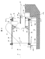
粒子線照射システムは、概略、図11に示すように、加速器(例えば、シンクロトロン加速器及びサイクルトロン加速器のいずれか)に接続される、HEBT系15のビーム経路16、GABT系20のビーム経路21及びビーム経路21に接続される照射装置29を有する。GABT系20及び照射装置29は、回転ガントリー(図示せず)に設置されている。ステアリング電磁石HH1及びHH2及びビーム位置モニタHP1及びHP2がビーム経路16に沿って配置される。35は、HEBT系15とGABT系20の取り合い部である。   As shown in FIG. 11 schematically, the particle beam irradiation system includes a beam path 16 of the HEBT system 15 and a beam path 21 of the GABT system 20 connected to an accelerator (for example, one of a synchrotron accelerator and a cycletron accelerator). And an irradiation device 29 connected to the beam path 21. The GABT system 20 and the irradiation device 29 are installed in a rotating gantry (not shown). Steering electromagnets HH 1 and HH 2 and beam position monitors HP 1 and HP 2 are arranged along the beam path 16. Reference numeral 35 denotes a joint portion between the HEBT system 15 and the GABT system 20.

発明者らは、粒子線照射システムによる患部の治療を開始した後においてイオンビームが照射装置の中心軸からずれた場合でも、ビーム軌道の調整を精度良く行うことができる粒子線照射システムを実現するために種々の検討を行った。   The inventors realize a particle beam irradiation system capable of accurately adjusting the beam trajectory even when the ion beam is deviated from the central axis of the irradiation device after the treatment of the affected area by the particle beam irradiation system is started. Various studies were conducted for this purpose.

発明者らは、その検討において、患者の治療開始後照射装置29の中心軸に垂直な平面においてイオンビームがこの中心軸からずれる原因が、粒子線照射システムを据え付けている建屋の、竣工後の時間経過によるゆがみ等によってHEBT系15のビーム経路16が変形することにあることを突き止めた。このHEBT系のビーム経路16の変形は、目に見えるほどではなく実際には極めて僅かである。   In the examination, the inventors found that the cause of the ion beam deviating from the central axis in a plane perpendicular to the central axis of the irradiation device 29 after the start of treatment of the patient after the completion of the building where the particle beam irradiation system is installed. It has been found that the beam path 16 of the HEBT system 15 is deformed due to distortion due to passage of time. The deformation of the beam path 16 of this HEBT system is not visible and is actually very slight.

また、発明者らは、回転ガントリー自体は剛性が高くその支持構造が強固であるため、上記した建屋のゆがみ等の影響を受け難く、回転ガントリーに取り付けられたGABT系20及び照射装置29では上記したゆがみ等に基づいた変形が生じないということも新たに見出した。GABT系20及び照射装置29は建屋のゆがみ等による変形が生じないため、発明者らは、建屋のゆがみ等によりHEBT系15のビーム経路16に変形が生じたときには、取り合い部35においてHEBT系15の出口の中心の位置とGABT系20の入口の中心の位置のずれが生じるだけであることを見出した。HEBT系15のビーム経路16に変形により、ビーム経路16内を通過するイオンビームがGABT系20の入口の中心の位置を通過しなくなる。このため、このイオンビームは、照射装置29内で、照射装置29の中心軸に垂直な平面においてこの中心軸からずれてしまう。   In addition, since the rotating gantry itself has high rigidity and its support structure is strong, the inventors are hardly affected by the above-described distortion of the building, and the GABT system 20 and the irradiation device 29 attached to the rotating gantry have the above-mentioned. It has also been newly found that no deformation based on the distortion or the like occurs. Since the GABT system 20 and the irradiation device 29 are not deformed due to the distortion of the building or the like, the inventors, when the beam path 16 of the HEBT system 15 is deformed due to the distortion or the like of the building, the HEBT system 15 at the joint portion 35. It has been found that there is only a deviation between the position of the center of the outlet of the gas outlet and the position of the center of the inlet of the GABT system 20. Due to the deformation of the beam path 16 of the HEBT system 15, the ion beam passing through the beam path 16 does not pass through the center position of the entrance of the GABT system 20. For this reason, the ion beam is shifted from the central axis in a plane perpendicular to the central axis of the irradiation device 29 in the irradiation device 29.

上記の新たに見出した知見を考慮して検討した結果、発明者らは、以下に記載するように、イオンビームの照射による患者への治療を開始後に、建屋のゆがみ等によりHEBT系15のビーム経路16に変形が生じた場合においてもビーム軌道の調整を精度良く行うことができる粒子線照射システムを実現できることを見出した。また、治療開始後におけるビーム軌道の調整であるため、ビーム軌道の調整に要する時間を短縮することが望まれる。このような粒子線照射システムを実現するためには、治療を開始した後におけるビーム軌道の調整では、照射装置のビーム位置モニタで測定されたビーム位置を用いて、特開2011−5096号公報に記載されたようにGABT系のステアリング電磁石に供給する励磁電流(励磁量)を調節するのではなく、HEBT系のステアリング電磁石に供給する励磁電流を調節すればよいのである。   As a result of examination in consideration of the above newly found knowledge, the inventors, as described below, have started the treatment of the patient with ion beam irradiation, and then the beam of the HEBT system 15 due to distortion of the building or the like. It has been found that a particle beam irradiation system capable of accurately adjusting the beam trajectory can be realized even when the path 16 is deformed. In addition, since the beam trajectory is adjusted after the start of treatment, it is desired to shorten the time required for the beam trajectory adjustment. In order to realize such a particle beam irradiation system, Japanese Patent Application Laid-Open No. 2011-5096 uses a beam position measured by a beam position monitor of an irradiation apparatus in beam trajectory adjustment after starting treatment. Instead of adjusting the excitation current (excitation amount) supplied to the GABT steering electromagnet as described, the excitation current supplied to the HEBT steering electromagnet may be adjusted.

HEBT系とGABT系の取り合い部に対するビーム軌道の調整を説明する前に、HEBT系の構成についてもう少し具体的に説明する。ステアリング電磁石HH1及びHH2は、特許第4299269号公報に記載されるように、それぞれ一対のステアリング電磁石を有する。ステアリング電磁石HH1は、一対のステアリング電磁石として、ビーム経路16に垂直な平面内で水平方向(X方向)におけるイオンビームの位置を調節するX方向ステアリング電磁石、及びその垂直な平面内で水平方向と直交する方向(Y方向)におけるイオンビームの位置を調節するY方向ステアリング電磁石を有する。ステアリング電磁石HH2も、同様に、一対のステアリング電磁石であるX方向ステアリング電磁石及びY方向ステアリング電磁石を有する。ビーム位置モニタHP1及びHP2のそれぞれも、特許第4299269号公報に記載されるように、一対のビーム位置モニタである、X方向におけるイオンビームの位置を測定するX方向ビーム位置モニタ及びY方向におけるイオンビームの位置を測定するY方向ビーム位置モニタを有する。   Before explaining the adjustment of the beam trajectory with respect to the HEBT system and GABT system, the configuration of the HEBT system will be described more specifically. The steering electromagnets HH1 and HH2 each have a pair of steering electromagnets as described in Japanese Patent No. 4299269. The steering electromagnet HH1 is, as a pair of steering electromagnets, an X direction steering electromagnet that adjusts the position of the ion beam in the horizontal direction (X direction) in a plane perpendicular to the beam path 16, and an orthogonal to the horizontal direction in the vertical plane. A Y-direction steering electromagnet that adjusts the position of the ion beam in the direction of movement (Y-direction). Similarly, the steering electromagnet HH2 includes a pair of steering electromagnets, an X-direction steering electromagnet and a Y-direction steering electromagnet. As described in Japanese Patent No. 4299269, each of the beam position monitors HP1 and HP2 is a pair of beam position monitors, an X-direction beam position monitor that measures the position of the ion beam in the X direction, and an ion in the Y direction. It has a Y-direction beam position monitor that measures the position of the beam.

粒子線照射システムの据え付け後において粒子線照射システムの試運転の期間において実施される、HEBT系とGABT系の取り合い部35に対するビーム軌道の調整が実施され、さらに、GABT系におけるビーム軌道の調整が実施される。   The beam trajectory adjustment for the HEBT system and GABT system joint 35 is carried out during the trial operation period of the particle beam irradiation system after the installation of the particle beam irradiation system, and further the beam trajectory adjustment in the GABT system is performed. Is done.

図11を用いて、その試運転の期間において実施される取り合い部35に対するビーム軌道の調整を説明する。試運転の期間において、イオンビームが加速器からビーム経路16に出射される。ビーム経路16に出射されたイオンビームのX方向及びY方向のそれぞれにおけるビーム位置が、回転ガントリーが任意の或る回転角度まで回転されている状態で、ビーム位置モニタHP1及びHP2のそれぞれによって測定される。ビーム位置モニタHP1及びHP2がそれぞれ配置された位置で測定されたそれらのビーム位置に基づいて、X方向におけるビーム軌道の勾配及びY方向におけるビーム軌道の勾配を求め、さらに、これらの勾配、及びビーム位置モニタHP1が配置された位置でのX方向及びY方向におけるそれぞれのビーム位置に基づいて、取り合い部35におけるビーム経路21の入口でのイオンビームの通過位置を求める。   With reference to FIG. 11, the adjustment of the beam trajectory with respect to the mating portion 35 performed during the trial operation period will be described. During the test run, an ion beam is emitted from the accelerator to the beam path 16. The beam position in each of the X direction and Y direction of the ion beam emitted to the beam path 16 is measured by each of the beam position monitors HP1 and HP2 with the rotating gantry rotated to any arbitrary rotation angle. The Based on the beam positions measured at the positions where the beam position monitors HP1 and HP2 are respectively arranged, the gradient of the beam trajectory in the X direction and the gradient of the beam trajectory in the Y direction are obtained. Based on the respective beam positions in the X direction and the Y direction at the position where the position monitor HP1 is disposed, the passing position of the ion beam at the entrance of the beam path 21 in the joint portion 35 is obtained.

ビーム経路21の入口でのイオンビームの通過位置がビーム経路21の入口での設定位置からずれているとき、このずれを補償してビーム経路21の入口でのイオンビームの通過位置を設定位置(例えば、ビーム経路21の入口の中心位置)に一致させる、ステアリング電磁石HH1及びHH2のそれぞれに含まれるX方向ステアリング電磁石及びY方向ステアリング電磁石のそれぞれの励磁電流を算出する。これらのステアリング電磁石に対してそれぞれ算出された上記の励磁電流は、回転ガントリーの前述の任意の或る回転角度での値である。   When the ion beam passage position at the entrance of the beam path 21 is deviated from the set position at the entrance of the beam path 21, this deviation is compensated for and the ion beam passage position at the entrance of the beam path 21 is set to the set position ( For example, the respective excitation currents of the X-direction steering electromagnet and the Y-direction steering electromagnet included in each of the steering electromagnets HH1 and HH2 that match the central position of the entrance of the beam path 21 are calculated. The above-described excitation current calculated for each of these steering electromagnets is a value at the aforementioned arbitrary rotation angle of the rotating gantry.

なお、取り合い部35に対するビーム軌道の調整はイオンビームの設定されたエネルギーごとに実施され、前述の任意の或る回転角度における、設定された各エネルギーに対してステアリング電磁石HH1及びHH2のそれぞれのX方向ステアリング電磁石及びY方向ステアリング電磁石に供給される各励磁電流が算出される。このようにして、HEBT系とGABT系の取り合い部35に対するビーム軌道の調整が終了する。   The adjustment of the beam trajectory with respect to the joint portion 35 is performed for each set energy of the ion beam, and the X of each of the steering electromagnets HH1 and HH2 is set for each set energy at an arbitrary certain rotation angle described above. Each excitation current supplied to the direction steering electromagnet and the Y direction steering electromagnet is calculated. In this way, the adjustment of the beam trajectory with respect to the HEBT system and GABT system joint 35 is completed.

上記した取り合い部35に対するビーム軌道の調整後に、上記の試運転の期間において、GABT系におけるビーム軌道の調整が実施される。このGABT系におけるビーム軌道の調整を、図12を用いて説明する。   After the adjustment of the beam trajectory with respect to the joint portion 35 described above, the adjustment of the beam trajectory in the GABT system is performed during the trial operation period. Adjustment of the beam trajectory in the GABT system will be described with reference to FIG.

図11には図示していないが、粒子線照射システムは、図12に示すように、ステアリング電磁石GH1及びGH2をGABT系20のビーム経路21に沿って配置しており、ビーム位置モニタPRM及びSPMを照射装置29に設置している。ステアリング電磁石GH1及びGH2のそれぞれも、一対のステアリング電磁石を有する。ステアリング電磁石GH1は、一対のステアリング電磁石である、ビーム経路21に垂直な平面内で水平方向(X方向)におけるイオンビームの位置を調節するX方向ステアリング電磁石、及びその垂直な平面内で水平方向と直交する方向(Y方向)におけるイオンビームの位置を調節するY方向ステアリング電磁石を有する。ステアリング電磁石GH2も、同様に、一対のステアリング電磁石であるX方向ステアリング電磁石及びY方向ステアリング電磁石を有する。前述したビーム経路21に垂直な平面内でのX方向及びこのX方向と直交するY方向のそれぞれは、回転ガントリーの回転角度が0°のときにおける方向である。   Although not shown in FIG. 11, in the particle beam irradiation system, as shown in FIG. 12, steering electromagnets GH1 and GH2 are arranged along the beam path 21 of the GABT system 20, and beam position monitors PRM and SPM are arranged. Is installed in the irradiation device 29. Each of the steering electromagnets GH1 and GH2 also has a pair of steering electromagnets. The steering electromagnet GH1 is a pair of steering electromagnets, an X direction steering electromagnet that adjusts the position of the ion beam in the horizontal direction (X direction) in a plane perpendicular to the beam path 21, and a horizontal direction in the vertical plane. A Y-direction steering electromagnet that adjusts the position of the ion beam in the orthogonal direction (Y direction) is provided. Similarly, the steering electromagnet GH2 includes a pair of steering electromagnets, an X-direction steering electromagnet and a Y-direction steering electromagnet. Each of the X direction in the plane perpendicular to the beam path 21 and the Y direction orthogonal to the X direction is a direction when the rotation angle of the rotating gantry is 0 °.

また、ビーム位置モニタPRM及びSPMのそれぞれも、特許第4299269号公報に記載されるように、一対のビーム位置モニタである、X方向におけるイオンビームの位置を測定するX方向ビーム位置モニタ及びY方向におけるイオンビームの位置を測定するY方向ビーム位置モニタを有する。なお、照射装置29におけるX方向及びY方向は照射装置29の中心軸に垂直な平面内での方向である。照射装置29内でのそのX方向は前述したビーム経路16及び21のそれぞれに垂直な各平面内における水平方向(X方向)に対応し、照射装置29内でのそのY方向は前述したビーム経路16及び21のそれぞれに垂直な各平面内における水平方向と直交する方向(Y方向)に対応している。   Each of the beam position monitors PRM and SPM is also a pair of beam position monitors, as described in Japanese Patent No. 4299269, and an X direction beam position monitor and a Y direction that measure the position of the ion beam in the X direction. And a Y-direction beam position monitor for measuring the position of the ion beam. The X direction and the Y direction in the irradiation device 29 are directions in a plane perpendicular to the central axis of the irradiation device 29. The X direction in the irradiation device 29 corresponds to the horizontal direction (X direction) in each plane perpendicular to the beam paths 16 and 21 described above, and the Y direction in the irradiation device 29 corresponds to the beam path described above. This corresponds to the direction (Y direction) orthogonal to the horizontal direction in each plane perpendicular to 16 and 21.

加速器から出射されたイオンビームは、ビーム経路16及び21を通って照射装置29に達する。照射装置29に取り付けられたビーム位置モニタPRM及びSPMのそれぞれは、ビーム位置モニタPRM及びSPMのそれぞれが配置された各位置においてイオンビームのX方向及びY方向のそれぞれにおけるビーム位置を測定する。これらの測定されたビーム位置に基づいて、照射装置29内でのX方向及びY方向におけるビーム軌道のそれぞれの勾配を上記した取り合い部35に対するビーム軌道の調整と同様に求める。X方向及びY方向におけるビーム軌道のそれぞれの勾配が0でなく、ビーム位置モニタPRM及びSPMのそれぞれが配置された各位置でX方向及びY方向における、照射装置29の中心軸からの変位が0でないとき、各勾配及び各変位がそれぞれ0になる、ステアリング電磁石GH1及びGH2のそれぞれに含まれるX方向ステアリング電磁石及びY方向ステアリング電磁石のそれぞれの励磁電流を算出する。   The ion beam emitted from the accelerator reaches the irradiation device 29 through the beam paths 16 and 21. Each of the beam position monitors PRM and SPM attached to the irradiation device 29 measures the beam position in each of the X direction and the Y direction of the ion beam at each position where the beam position monitors PRM and SPM are arranged. Based on these measured beam positions, the respective gradients of the beam trajectories in the X direction and Y direction in the irradiation device 29 are obtained in the same manner as the beam trajectory adjustment for the joint portion 35 described above. The respective gradients of the beam trajectories in the X direction and the Y direction are not 0, and the displacement from the central axis of the irradiation device 29 in the X direction and the Y direction is 0 at each position where the beam position monitors PRM and SPM are respectively arranged. Otherwise, the respective excitation currents of the X-direction steering electromagnet and the Y-direction steering electromagnet included in each of the steering electromagnets GH1 and GH2 are calculated so that each gradient and each displacement become 0, respectively.

なお、GABT系におけるビーム軌道の調整は、イオンビームの設定されたエネルギーごとで回転ガントリーの設定された回転角度ごとに実施され、設定された各エネルギーに対して設定された回転角度ごとにステアリング電磁石GH1及びGH2のそれぞれのX方向ステアリング電磁石及びY方向ステアリング電磁石に供給される各励磁電流が算出される。このようにして、GABT系におけるビーム軌道の調整が終了する。   The beam trajectory adjustment in the GABT system is performed for each set rotation angle of the rotating gantry for each set energy of the ion beam, and the steering electromagnet for each set rotation angle for each set energy. Each excitation current supplied to the X direction steering electromagnet and the Y direction steering electromagnet of GH1 and GH2 is calculated. In this way, adjustment of the beam trajectory in the GABT system is completed.

試運転時における取り合い部35に対するビーム軌道の調整及びGABT系におけるビーム軌道の調整が実施された後、基準回転角度におけるステアリング電磁石HH1及びHH2のそれぞれのX方向ステアリング電磁石及びY方向ステアリング電磁石の各励磁電流、基準回転角度におけるビーム位置モニタPRM及びSPMのそれぞれの位置でのX方向及びY方向の各ビーム位置、及び設定された回転ガントリーの回転角度ごとの、ステアリング電磁石GH1及びGH2のそれぞれのX方向ステアリング電磁石及びY方向ステアリング電磁石の各励磁電流のそれぞれの情報が、回転角度テーブルとして、イオンビームの設定されたエネルギーごとに、前述の記憶装置に格納される。   After adjustment of the beam trajectory with respect to the joint portion 35 in the trial operation and adjustment of the beam trajectory in the GABT system, the respective excitation currents of the X-direction steering electromagnet and the Y-direction steering electromagnet of the steering electromagnets HH1 and HH2 at the reference rotation angle are performed. Steering electromagnets GH1 and GH2 for each X-direction steering for each beam position in the X-direction and Y-direction at the respective positions of the beam position monitors PRM and SPM at the reference rotation angle and for each set rotation angle of the rotating gantry Information of each excitation current of the electromagnet and the Y-direction steering electromagnet is stored in the above-described storage device as a rotation angle table for each set energy of the ion beam.

以上に述べた試運転の期間におけるビーム軌道の調整が終了した後、粒子線照射システムを用いた、患者の患部へのイオンビームの照射が行われ、患部の治療が実施される。患者への治療が開始されてから所定の時間が経過したとき、イオンビームの、照射装置29の中心軸からのずれを補償するために、粒子線照射システムにおいてビーム軌道の調整が行われる。   After the adjustment of the beam trajectory in the trial operation period described above is completed, the affected area of the patient is irradiated with the ion beam using the particle beam irradiation system, and the affected area is treated. When a predetermined time has elapsed since the start of treatment for the patient, the beam trajectory is adjusted in the particle beam irradiation system in order to compensate for the deviation of the ion beam from the central axis of the irradiation device 29.

粒子線照射システムを用いた患者の治療が開始された後におけるビーム軌道の調整を、図13を用いて説明する。このビーム軌道の調整において、加速器から出射されたイオンビームがビーム経路16及び21を通って照射装置29に達し、照射装置29内でのイオンビームの位置がビーム位置モニタPRM及びSPMのそれぞれによって測定される。このとき、回転ガントリーは前述の任意の或る回転角度まで回転されている。これらのビーム位置モニタで測定されたそれぞれのビーム位置に基づいて求めた、照射装置29内でのX方向及びY方向におけるビーム軌道のそれぞれの勾配が0でなく、ビーム位置モニタPRM及びSPMのそれぞれが配置された各位置でX方向及びY方向における、イオンビームの、照射装置29の中心軸からの変位が0でないとき、各勾配及び各変位がそれぞれ0になる、ステアリング電磁石HH1及びHH2のそれぞれのX方向ステアリング電磁石及びY方向ステアリング電磁石のそれぞれの励磁電流を算出する。   The adjustment of the beam trajectory after the treatment of the patient using the particle beam irradiation system is started will be described with reference to FIG. In this beam trajectory adjustment, the ion beam emitted from the accelerator reaches the irradiation device 29 through the beam paths 16 and 21, and the position of the ion beam in the irradiation device 29 is measured by the beam position monitors PRM and SPM, respectively. Is done. At this time, the rotating gantry is rotated to any one of the aforementioned rotation angles. The respective gradients of the beam trajectories in the X direction and the Y direction in the irradiation device 29 obtained based on the respective beam positions measured by these beam position monitors are not 0, and the beam position monitors PRM and SPM respectively. When the displacement of the ion beam from the central axis of the irradiation device 29 in the X direction and the Y direction is not 0 at each of the positions where each of the steering electromagnets HH1 and HH2, respectively, The respective excitation currents of the X direction steering electromagnet and the Y direction steering electromagnet are calculated.

なお、治療開始後におけるビーム軌道の調整はイオンビームの設定されたエネルギーごとに実施され、基準回転角度で設定されたエネルギーごとにステアリング電磁石HH1及びHH2のそれぞれのX方向ステアリング電磁石及びY方向ステアリング電磁石に供給される各励磁電流が算出される。このようにして、治療開始後におけるビーム軌道の調整が終了する。   Adjustment of the beam trajectory after the start of treatment is performed for each set energy of the ion beam, and the X direction steering electromagnet and the Y direction steering electromagnet of the steering electromagnets HH1 and HH2 for each energy set at the reference rotation angle. Each excitation current supplied to is calculated. In this way, adjustment of the beam trajectory after the start of treatment is completed.

ビーム位置モニタPRM及びSPMで測定されそれぞれのビーム位置を用いてHEBT系15に配置されたステアリング電磁石HH1及びHH2のそれぞれの励磁電流を算出するので、治療開始後におけるビーム軌道の調整に要する時間を短縮することができる。   Since the respective excitation currents of the steering electromagnets HH1 and HH2 measured in the beam position monitors PRM and SPM and arranged in the HEBT system 15 are calculated using the respective beam positions, the time required for adjusting the beam trajectory after the start of treatment is calculated. It can be shortened.

以上に述べた検討結果を反映した本発明の各実施例を以下に説明する。   Each embodiment of the present invention reflecting the above-described examination results will be described below.

本発明の好適な一実施例である実施例1の粒子線照射システムを、図1〜図4を用いて以下に説明する。   A particle beam irradiation system according to a first embodiment which is a preferred embodiment of the present invention will be described below with reference to FIGS.

本実施例の粒子線照射システム1は、建屋(図示せず)内に配置されて建屋の床面に設置される。この粒子線照射システム1は、図1に示すように、イオンビーム発生装置2、高エネルギービーム輸送系(HEBT系)15、ガントリービーム輸送系(GABT系)20、回転ガントリー26、照射装置29及び制御システム59を備えている。粒子線照射システム1では、がんの患部(ビーム照射対象)に照射するイオンビームとして、陽子イオンビームが用いられる。陽子イオンビームの替りに炭素イオンビームを用いてもよい。   The particle beam irradiation system 1 of a present Example is arrange | positioned in a building (not shown), and is installed in the floor surface of a building. As shown in FIG. 1, the particle beam irradiation system 1 includes an ion beam generator 2, a high energy beam transport system (HEBT system) 15, a gantry beam transport system (GABT system) 20, a rotating gantry 26, an irradiation apparatus 29, and A control system 59 is provided. In the particle beam irradiation system 1, a proton ion beam is used as an ion beam irradiated to a cancer affected part (beam irradiation target). A carbon ion beam may be used instead of the proton ion beam.

イオンビーム発生装置2は、イオン源(図示せず)、前段加速器である直線加速器14及びシンクロトロン加速器3を有する。シンクロトロン加速器13は、イオンビームの周回軌道を構成する環状のビームダクト4、入射器5、イオンビームに高周波電圧を印加する高周波加速空胴(高周波加速装置)8、複数の偏向電磁石6、複数の四極電磁石7、出射用の高周波印加装置9、出射用のセプタム電磁石13を有する。ビームダクト4に連絡される入射器5は、真空ダクトにより直線加速器14に接続される。イオン源も直線加速器14に接続される。高周波印加装置9は、出射用高周波電極10、高周波電源11及び開閉スイッチ12を含んでいる。出射用高周波電極10は、環状のビームダクト4に取り付けられ、そして、開閉スイッチ12を介して高周波電源11に接続される。各偏向電磁石6、各四極電磁石7、高周波加速空胴8及びセプタム電磁石13は、図1に示すように、ビームダクト4に沿って配置されている。   The ion beam generator 2 includes an ion source (not shown), a linear accelerator 14 that is a pre-stage accelerator, and a synchrotron accelerator 3. The synchrotron accelerator 13 includes an annular beam duct 4 that constitutes an orbit of the ion beam, an injector 5, a high-frequency acceleration cavity (high-frequency accelerator) 8 that applies a high-frequency voltage to the ion beam, a plurality of deflection electromagnets 6, a plurality The quadrupole electromagnet 7, the high frequency application device 9 for emission, and the septum electromagnet 13 for emission. The injector 5 connected to the beam duct 4 is connected to the linear accelerator 14 by a vacuum duct. An ion source is also connected to the linear accelerator 14. The high-frequency applying device 9 includes an output high-frequency electrode 10, a high-frequency power source 11, and an open / close switch 12. The emission high-frequency electrode 10 is attached to the annular beam duct 4 and is connected to a high-frequency power source 11 via an open / close switch 12. Each deflection electromagnet 6, each quadrupole electromagnet 7, the high-frequency acceleration cavity 8, and the septum electromagnet 13 are disposed along the beam duct 4 as shown in FIG. 1.

図4Aに示すように、各偏向電磁石6、各四極電磁石7及びセプタム電磁石13が別々の電源55に接続される。高周波加速空胴8が高周波電源装置57に接続される。   As shown in FIG. 4A, each deflection electromagnet 6, each quadrupole electromagnet 7, and septum electromagnet 13 are connected to separate power supplies 55. The high frequency acceleration cavity 8 is connected to the high frequency power supply device 57.

HEBT系(第1ビーム輸送系)15は、シンクロトロン加速器13のセプタム電磁石13に接続されるビーム経路(ビームダクト)16を有しており、このビーム経路16に沿って、シンクロトロン加速器3から照射装置29に向かって複数の4極電磁石18、偏向電磁石17、複数の4極電磁石19、ステアリング電磁石HH1(第1ステアリング電磁石)、ステアリング電磁石HH2(第2ステアリング電磁石)、ビーム位置モニタHP1(第1ビーム位置測定装置)及びビーム位置モニタHP2(第2ビーム位置測定装置)を配置して構成される。4極電磁石19は、ステアリング電磁石HH1とステアリング電磁石HH2の間にも配置される。ステアリング電磁石HH1及びHH2は、前述したように、X方向ステアリング電磁石及びY方向ステアリング電磁石をそれぞれ有する。偏向電磁石17及び四極電磁石18,19が、図4Aに示されるように、別々の電源56に接続される。さらに、ステアリング電磁石HH1が電源58Aに、ステアリング電磁石HH2が電源58Bにそれぞれ接続される。ビーム位置モニタHP1及びHP2のそれぞれは、ステアリング電磁石HH2よりもHEBT系15とGABT20系の取り合い部35側に配置される。   The HEBT system (first beam transport system) 15 has a beam path (beam duct) 16 connected to the septum electromagnet 13 of the synchrotron accelerator 13, and from the synchrotron accelerator 3 along the beam path 16. A plurality of quadrupole electromagnets 18, a deflection electromagnet 17, a plurality of quadrupole electromagnets 19, a steering electromagnet HH1 (first steering electromagnet), a steering electromagnet HH2 (second steering electromagnet), a beam position monitor HP1 (first) 1 beam position measuring device) and a beam position monitor HP2 (second beam position measuring device) are arranged. The quadrupole electromagnet 19 is also disposed between the steering electromagnet HH1 and the steering electromagnet HH2. As described above, the steering electromagnets HH1 and HH2 include an X-direction steering electromagnet and a Y-direction steering electromagnet, respectively. The deflection electromagnet 17 and the quadrupole electromagnets 18 and 19 are connected to separate power sources 56 as shown in FIG. 4A. Further, the steering electromagnet HH1 is connected to the power source 58A, and the steering electromagnet HH2 is connected to the power source 58B. Each of the beam position monitors HP1 and HP2 is disposed closer to the mating portion 35 side of the HEBT system 15 and the GABT 20 system than the steering electromagnet HH2.

GABT系(第2ビーム輸送系)20は、ビーム経路(ビームダクト)21を有しており、このビーム経路21に沿って、シンクロトロン加速器3から照射装置29に向かって偏向電磁石22、複数の4極電磁石25、ステアリング電磁石GH1(第3ステアリング電磁石)、ステアリング電磁石GH2(第4ステアリング電磁石)、及び偏向電磁石23及び24を配置して構成される。4極電磁石25は、ステアリング電磁石HH1とステアリング電磁石HH2の間にも配置される。ステアリング電磁石GH1及びGH2も、前述したように、X方向ステアリング電磁石及びY方向ステアリング電磁石をそれぞれ有する。ビーム経路21は回転ガントリー26に設置されており、偏向電磁石22〜25、複数の4極電磁石25、及びステアリング電磁石GH1及びGH2も回転ガントリー26に設置されている。ビーム経路21は、取り合い部35においてビーム経路16に連絡される。ビーム経路21は回転ガントリー26によって回転されるため、ビーム経路21はビーム経路16に直接接続されてはいない。偏向電磁石22〜24及び四極電磁石25が、図4Aに示されるように、別々の電源56に接続される。さらに、ステアリング電磁石GH1が電源58Cに、ステアリング電磁石GH2が電源58Dにそれぞれ接続される。   The GABT system (second beam transport system) 20 has a beam path (beam duct) 21, and along the beam path 21, a deflecting electromagnet 22 and a plurality of electromagnets 22 from the synchrotron accelerator 3 toward the irradiation device 29. A 4-pole electromagnet 25, a steering electromagnet GH1 (third steering electromagnet), a steering electromagnet GH2 (fourth steering electromagnet), and deflection electromagnets 23 and 24 are arranged. The quadrupole electromagnet 25 is also disposed between the steering electromagnet HH1 and the steering electromagnet HH2. As described above, the steering electromagnets GH1 and GH2 also have an X-direction steering electromagnet and a Y-direction steering electromagnet, respectively. The beam path 21 is installed in the rotating gantry 26, and the deflecting electromagnets 22 to 25, the plurality of quadrupole electromagnets 25, and the steering electromagnets GH 1 and GH 2 are also installed in the rotating gantry 26. The beam path 21 is connected to the beam path 16 at the joint 35. Since the beam path 21 is rotated by the rotating gantry 26, the beam path 21 is not directly connected to the beam path 16. The deflection electromagnets 22-24 and the quadrupole electromagnet 25 are connected to separate power sources 56, as shown in FIG. 4A. Further, the steering electromagnet GH1 is connected to the power source 58C, and the steering electromagnet GH2 is connected to the power source 58D.

照射装置29は、2つの走査電磁石(イオンビーム走査装置)30及び31、ビーム位置モニPRM及びSPM、及び線量モニタ32を備える。照射装置29は、回転ガントリー26に取り付けられ、偏向電磁石24の下流に配置される。走査電磁石30及び31、ビーム位置モニタPRM(第3ビーム位置測定装置)、ビーム位置モニタSPM(第4ビーム位置測定装置)及び線量モニタ32は、この順に、照射装置29のケーシング(図示せず)内において偏向電磁石24から照射装置29の出口に向かって照射装置29の中心軸に沿って配置される。走査電磁石30はイオンビームを照射装置29の中心軸に垂直な平面内において偏向させてX方向に走査し、走査電磁石31はイオンビームをその平面内において偏向させてX方向と直交するY方向に走査する。患者34が横たわる治療台33が、照射装置29に対向するように配置される。   The irradiation device 29 includes two scanning electromagnets (ion beam scanning devices) 30 and 31, beam position monitors PRM and SPM, and a dose monitor 32. The irradiation device 29 is attached to the rotating gantry 26 and is arranged downstream of the deflection electromagnet 24. The scanning electromagnets 30 and 31, the beam position monitor PRM (third beam position measuring device), the beam position monitor SPM (fourth beam position measuring device), and the dose monitor 32 are arranged in this order in the casing (not shown) of the irradiation device 29. It is arranged along the central axis of the irradiation device 29 from the deflection electromagnet 24 toward the exit of the irradiation device 29. The scanning electromagnet 30 deflects the ion beam in a plane perpendicular to the central axis of the irradiation device 29 and scans in the X direction, and the scanning electromagnet 31 deflects the ion beam in the plane and in the Y direction orthogonal to the X direction. Scan. The treatment table 33 on which the patient 34 lies is disposed so as to face the irradiation device 29.

制御システム59は、中央制御装置60、加速器・輸送系制御装置64、ガントリー制御装置73、走査制御装置76及びデータベース81を有する(図1参照)。中央制御装置60は、中央演算装置(CPU)61及びCPU61に接続されたメモリ62を有する。CPU61は照射制御装置93、ビーム軌道調整装置94(第2ビーム軌道調整装置)及びビーム軌道調整装置98(第1ビーム軌道調整装置)を含んでいる(図1参照)。加速器・輸送系制御装置64、ガントリー制御装置73及び走査制御装置76は、CPU61の照射制御装置93、ビーム軌道調整装置94及びビーム軌道調整装置98にそれぞれ接続される。データベース81は照射制御装置93に接続される。粒子線照射システム1は治療計画装置82を有し、治療計画装置82はデータベース81に接続される。   The control system 59 includes a central control device 60, an accelerator / transport system control device 64, a gantry control device 73, a scanning control device 76, and a database 81 (see FIG. 1). The central controller 60 has a central processing unit (CPU) 61 and a memory 62 connected to the CPU 61. The CPU 61 includes an irradiation control device 93, a beam trajectory adjusting device 94 (second beam trajectory adjusting device), and a beam trajectory adjusting device 98 (first beam trajectory adjusting device) (see FIG. 1). The accelerator / transport system control device 64, the gantry control device 73, and the scanning control device 76 are connected to the irradiation control device 93, the beam trajectory adjustment device 94, and the beam trajectory adjustment device 98 of the CPU 61, respectively. The database 81 is connected to the irradiation control device 93. The particle beam irradiation system 1 includes a treatment planning device 82, and the treatment planning device 82 is connected to a database 81.

ビーム軌道調整装置94は、図4Bに示すように、軌道調整制御装置95(第2軌道調整制御装置)、励磁電流演算装置63(第2励磁電流演算装置)及びテーブル作成装置96を有する。ビーム軌道調整装置97は、図4Bに示すように、軌道調整制御装置98(第1軌道調整制御装置)、励磁電流演算装置70(第1励磁電流演算装置)及び励磁電流更新装置99を有する。照射制御装置93、軌道調整制御装置95及び98、励磁電流演算装置63及び70、テーブル作成装置96及び励磁電流更新装置99は、メモリ62に接続される。入力装置100が、照射制御装置93、軌道調整制御装置95及び98に接続される(図4B参照)。   4B, the beam trajectory adjusting device 94 includes a trajectory adjusting control device 95 (second trajectory adjusting control device), an excitation current calculating device 63 (second exciting current calculating device), and a table creating device 96. 4B, the beam trajectory adjusting device 97 includes a trajectory adjusting control device 98 (first trajectory adjusting control device), an exciting current calculating device 70 (first exciting current calculating device), and an exciting current updating device 99. The irradiation control device 93, the trajectory adjustment control devices 95 and 98, the excitation current calculation devices 63 and 70, the table creation device 96 and the excitation current update device 99 are connected to the memory 62. The input device 100 is connected to the irradiation control device 93 and the trajectory adjustment control devices 95 and 98 (see FIG. 4B).

ビーム軌道調整装置94によって、粒子線照射システム1の据え付け後の試運転の期間におけるビーム軌道の調整が実施される。ビーム軌道調整装置97によって、粒子線照射システム1による患部の治療が開始された後におけるビーム軌道の調整が実施される。照射制御装置93によって、治療時においてビーム照射対象である患部にイオンビームを照射する制御が実施される。   The beam trajectory adjustment device 94 adjusts the beam trajectory during the trial operation period after the installation of the particle beam irradiation system 1. The beam trajectory adjustment device 97 adjusts the beam trajectory after the treatment of the affected area by the particle beam irradiation system 1 is started. The irradiation control device 93 performs control to irradiate the affected part which is a beam irradiation target at the time of treatment with an ion beam.

加速器・輸送系制御装置64は、図4Aに示すように、電磁石制御装置65、高周波電圧制御装置66、出射制御装置67、ビーム位置入力装置68、ステアリング電磁石制御装置69、エネルギー判定装置71及びメモリ72を有する。ガントリー制御装置73は、図4Aに示すように、回転制御装置74、回転角度判定装置75及び回転角度設定装置52を有する。また、走査制御装置76は、図4Aに示すように、照射位置制御装置77、線量判定装置78、層判定装置79及びメモリ80を有する。   As shown in FIG. 4A, the accelerator / transportation system control device 64 includes an electromagnet control device 65, a high frequency voltage control device 66, an emission control device 67, a beam position input device 68, a steering electromagnet control device 69, an energy determination device 71, and a memory. 72. The gantry control device 73 includes a rotation control device 74, a rotation angle determination device 75, and a rotation angle setting device 52, as shown in FIG. 4A. Further, the scanning control device 76 includes an irradiation position control device 77, a dose determination device 78, a layer determination device 79, and a memory 80, as shown in FIG. 4A.

照射制御装置93、ビーム軌道調整装置94及びビーム軌道調整装置98と加速器・輸送系制御装置64、ガントリー制御装置73及び走査制御装置76との具体的な接続状態を、図4A及び図4Bを用いて以下に説明する。照射制御装置93は、電磁石制御装置65、高周波電圧制御装置66、出射制御装置67、ステアリング電磁石制御装置69、メモリ72、回転制御装置74、照射位置制御装置77、線量判定装置78、層判定装置79及びメモリ80に、それぞれ、接続される。軌道調整制御装置95は、電磁石制御装置65、高周波電圧制御装置66、出射制御装置67、ビーム位置入力装置68、ステアリング電磁石制御装置69、エネルギー判定装置71、メモリ72、回転制御装置74、回転角度判定装置75及び回転角度設定装置52に、それぞれ、接続される。軌道調整制御装置98は、電磁石制御装置65、高周波電圧制御装置66、出射制御装置67、ビーム位置入力装置68、ステアリング電磁石制御装置69、エネルギー判定装置71、メモリ72及び回転制御装置74に、それぞれ、接続される。ビーム位置入力装置68は、ビーム位置モニタHP1,HP2,PRM及びSPMに接続される。角度検出器28(図2参照)が回転角度判定装置75に接続される。照射位置制御装置77が、電磁石制御装置65、高周波電圧制御装置66、出射制御装置67及びステアリング電磁石制御装置69に接続される。線量判定装置78が出射制御装置67に接続される。線量モニタ32が線量判定装置78に接続される。   4A and 4B show specific connection states of the irradiation control device 93, the beam trajectory adjustment device 94, the beam trajectory adjustment device 98, the accelerator / transport system control device 64, the gantry control device 73, and the scan control device 76. Will be described below. The irradiation control device 93 includes an electromagnet control device 65, a high-frequency voltage control device 66, an emission control device 67, a steering electromagnet control device 69, a memory 72, a rotation control device 74, an irradiation position control device 77, a dose determination device 78, and a layer determination device. 79 and the memory 80, respectively. The trajectory adjustment control device 95 includes an electromagnet control device 65, a high frequency voltage control device 66, an emission control device 67, a beam position input device 68, a steering electromagnet control device 69, an energy determination device 71, a memory 72, a rotation control device 74, and a rotation angle. The determination device 75 and the rotation angle setting device 52 are connected to each other. The trajectory adjustment control device 98 includes an electromagnet control device 65, a high frequency voltage control device 66, an emission control device 67, a beam position input device 68, a steering electromagnet control device 69, an energy determination device 71, a memory 72, and a rotation control device 74, respectively. Connected. The beam position input device 68 is connected to beam position monitors HP1, HP2, PRM and SPM. An angle detector 28 (see FIG. 2) is connected to the rotation angle determination device 75. An irradiation position control device 77 is connected to the electromagnet control device 65, the high frequency voltage control device 66, the emission control device 67, and the steering electromagnet control device 69. A dose determination device 78 is connected to the emission control device 67. A dose monitor 32 is connected to the dose determination device 78.

回転ガントリー26を、図2及び図3を用いて説明する。回転ガントリー26は、360°の範囲で回転が可能であり、リング状のフロントリング37及びリアリング38を有する円筒状の回転胴36を備える。フロントリング37が建屋の床面43に設置された支持装置39Aによって支持され、リアリング38がその床面43に設置された支持装置39Bによって支持される。支持装置39Aは、ロール支持部材40及び複数のサポートローラ41Aを含む。複数のサポートローラ41Aは、ロール支持部材40に回転可能に取り付けられる。フロントリング37はこれらのサポートローラ41Aで支持される。支持装置39Bも、支持装置39Aと同様に、ロール支持部材40(図示せず)及び複数のサポートローラ41Bを含む。複数のサポートローラ41Bは、ロール支持部材40に回転可能に取り付けられる。リアリング38はこれらのサポートローラ41Bで支持される。回転ガントリー26を回転させる回転装置(例えば、モータ)42が、リアリング38を支持する複数のサポートローラ41Bのうちの一つのサポートローラ41Bの回転軸に連結される。回転ガントリー26の回転角度を測定する角度検出器28が、フロントリング37を支持する複数のサポートローラ41Aのうちの一つのサポートローラ41Aの回転軸に連結される。なお、図1では、角度検出器28がビーム経路21に接触するように図示されているが、これは角度検出器28の配置を模式的に表したものである。   The rotating gantry 26 will be described with reference to FIGS. The rotating gantry 26 is rotatable in a range of 360 ° and includes a cylindrical rotating drum 36 having a ring-shaped front ring 37 and a rear ring 38. The front ring 37 is supported by a support device 39A installed on the floor surface 43 of the building, and the rear ring 38 is supported by a support device 39B installed on the floor surface 43 thereof. The support device 39A includes a roll support member 40 and a plurality of support rollers 41A. The plurality of support rollers 41 </ b> A are rotatably attached to the roll support member 40. The front ring 37 is supported by these support rollers 41A. Similarly to the support device 39A, the support device 39B also includes a roll support member 40 (not shown) and a plurality of support rollers 41B. The plurality of support rollers 41 </ b> B are rotatably attached to the roll support member 40. The rear ring 38 is supported by these support rollers 41B. A rotating device (for example, a motor) 42 that rotates the rotating gantry 26 is coupled to the rotating shaft of one of the support rollers 41B that supports the rear ring 38. An angle detector 28 that measures the rotation angle of the rotating gantry 26 is connected to the rotating shaft of one of the support rollers 41A that supports the front ring 37. In FIG. 1, the angle detector 28 is shown in contact with the beam path 21, but this schematically shows the arrangement of the angle detector 28.

回転胴36の内面に取り付けられた複数の支持部材48によって支持された治療室45が回転胴36内に設けられる。治療室45のフロントリング37側は開放されており、治療室45のリアリング38側は隔壁47によって封鎖されている。照射装置29は、回転胴36に取り付けられて回転胴36の中心に向かって伸びており、治療室45内の治療ケージ49に達している。照射装置29に接続された、GABT系20のビーム経路21は、図2に示すように、リアリング38側に向かって伸びており、回転ガントリー26の外側に位置する取り合い部35においてHEBT系15のビーム経路16に連絡される。なお、回転ガントリー26の中心線27(図1及び図2参照)は、回転ガントリー26の回転中心であり、取り合い部35においてビーム経路21の入口の中心を通る。   A treatment room 45 supported by a plurality of support members 48 attached to the inner surface of the rotary drum 36 is provided in the rotary drum 36. The front ring 37 side of the treatment room 45 is open, and the rear ring 38 side of the treatment room 45 is sealed by a partition wall 47. The irradiation device 29 is attached to the rotating drum 36 and extends toward the center of the rotating drum 36, and reaches the treatment cage 49 in the treatment room 45. As shown in FIG. 2, the beam path 21 of the GABT system 20 connected to the irradiation device 29 extends toward the rear ring 38, and the HEBT system 15 is located at the mating portion 35 located outside the rotating gantry 26. To the beam path 16. The center line 27 (see FIGS. 1 and 2) of the rotating gantry 26 is the rotating center of the rotating gantry 26 and passes through the center of the entrance of the beam path 21 at the joint portion 35.

治療台33は、図2に示すように、ベッド50、床面43よりも高くなっている治療台取付領域44に設置された三方向駆動機構53、三方向駆動機構53の上に設置された回転駆動機構54、及び回転駆動機構54に取り付けられたベッド50を有する。   As shown in FIG. 2, the treatment table 33 is installed on the bed 50 and the three-way drive mechanism 53 and the three-way drive mechanism 53 installed in the treatment table mounting region 44 that is higher than the floor surface 43. The rotary drive mechanism 54 has a bed 50 attached to the rotary drive mechanism 54.

本実施例の粒子線照射システム1におけるビーム軌道調整方法を、図5〜図7を用いて説明する。まず、粒子線照射システム1の据え付けが終了した後の試運転の期間におけるビーム軌道調整方法を、図5及び図6を用いて説明する。図5及び図6に示されたステップS1及びS3〜S24の各工程を含む手順を示す第1ビーム軌道調整プログラムは、メモリ62に記憶されている。さらに、メモリ62には、図7に示されたステップS23,S4,S5,S27,S7,S8,S16,S10,S28,S29及びS30の各工程を含む手順を示す第2ビーム軌道調整プログラムも記憶されている。オペレータが入力装置100からビーム軌道調整装置94の軌道調整制御装置95に第1軌道調整開始信号を入力したとき、軌道調整制御装置95は、メモリ62に格納されている、試運転の期間におけるビーム軌道の調整を実施する第1ビーム軌道調整プログラムを選択し、この第1ビーム軌道調整プログラムの手順に基づいて加速器・輸送系制御装置64及びガントリー制御装置73のそれぞれに含まれる各制御装置等に制御指令情報を出力し、試運転の期間におけるビーム軌道の調整が以下のように実施される。   A beam trajectory adjustment method in the particle beam irradiation system 1 of the present embodiment will be described with reference to FIGS. First, a beam trajectory adjustment method in a trial operation period after the installation of the particle beam irradiation system 1 is completed will be described with reference to FIGS. 5 and 6. A first beam trajectory adjustment program showing a procedure including steps S1 and S3 to S24 shown in FIGS. 5 and 6 is stored in the memory 62. Further, the memory 62 also has a second beam trajectory adjustment program showing a procedure including steps S23, S4, S5, S27, S7, S8, S16, S10, S28, S29 and S30 shown in FIG. It is remembered. When the operator inputs a first trajectory adjustment start signal from the input device 100 to the trajectory adjustment control device 95 of the beam trajectory adjustment device 94, the trajectory adjustment control device 95 stores the beam trajectory in the trial run period stored in the memory 62. The first beam trajectory adjustment program for performing the adjustment is selected, and the control devices included in the accelerator / transportation system control device 64 and the gantry control device 73 are controlled based on the procedure of the first beam trajectory adjustment program. The command information is output, and the beam trajectory adjustment during the test run is performed as follows.

イオン源及び直線加速器を起動する(ステップS1)。軌道調整制御装置95から制御指令情報を入力した加速器・輸送系制御装置64は、イオン源及び直線加速器14を起動する。イオン源で発生したイオン(例えば、陽子)が直線加速器14に入射され、加速される。直線加速器14から出射された陽子イオンビーム(以下、単に、イオンビームという)は、入射器5を通してシンクロトロン加速器3の環状のビームダクト4に入射される。イオンビームはビームダクト4内を周回する。   The ion source and the linear accelerator are activated (step S1). The accelerator / transport system controller 64 that has received control command information from the trajectory adjustment controller 95 activates the ion source and the linear accelerator 14. Ions (for example, protons) generated in the ion source enter the linear accelerator 14 and are accelerated. A proton ion beam (hereinafter simply referred to as an ion beam) emitted from the linear accelerator 14 is incident on the annular beam duct 4 of the synchrotron accelerator 3 through the injector 5. The ion beam circulates in the beam duct 4.

イオンビームのエネルギーを設定する(ステップS2)。オペレータが、入力装置100から、シンクロトロン加速器3から出射するイオンビームのエネルギーとして、例えば、最大の250MeVを入力する。このエネルギー「250MeV」は、軌道調整制御装置95に入力され、軌道調整制御装置95においてイオンビームのエネルギーとして設定される。   The ion beam energy is set (step S2). The operator inputs a maximum of 250 MeV, for example, as the energy of the ion beam emitted from the synchrotron accelerator 3 from the input device 100. This energy “250 MeV” is input to the trajectory adjustment control device 95 and set as the energy of the ion beam in the trajectory adjustment control device 95.

回転ガントリーを任意の或る回転角度まで回転させる(ステップS3)。軌道調整制御装置95から制御指令情報を入力した回転制御装置74は、回転装置42を駆動して、取り合い部35に対するビーム軌道の調整を実施する任意の或る回転角度(例えば、270°)まで回転ガントリー26を回転させ、回転ガントリー26はこの角度で保持される。任意の或る回転角度は、回転ガントリー26の回転範囲0°〜360°内の一つの回転角度であり、例えば、0°または10°であってもよい。回転角度判定装置75は、角度検出器28で測定された角度に基づいて回転ガントリー26が270°まで回転したことを確認する。   The rotating gantry is rotated to an arbitrary certain rotation angle (step S3). The rotation control device 74 that has received the control command information from the trajectory adjustment control device 95 drives the rotation device 42 to an arbitrary certain rotation angle (for example, 270 °) for adjusting the beam trajectory with respect to the joint portion 35. The rotating gantry 26 is rotated, and the rotating gantry 26 is held at this angle. Any given rotation angle is one rotation angle within the rotation range 0 ° to 360 ° of the rotating gantry 26, and may be, for example, 0 ° or 10 °. The rotation angle determination device 75 confirms that the rotation gantry 26 has rotated to 270 ° based on the angle measured by the angle detector 28.

イオンビームの設定エネルギーに基づいて加速器の電磁石に供給する励磁電流を制御する(ステップS4)。軌道調整制御装置95から制御指令情報を入力した電磁石制御装置65は、電源55を制御してビームダクト4に沿って配置された偏向電磁石6、四極電磁石6及びセプタム電磁石13のそれぞれに供給される励磁電流を、ステップS2で設定したイオンビームのエネルギー(250MeV)に対応する励磁電流に調節する。   The excitation current supplied to the electromagnet of the accelerator is controlled based on the set energy of the ion beam (step S4). The electromagnet controller 65 to which the control command information is input from the trajectory adjustment controller 95 is supplied to each of the deflection electromagnet 6, the quadrupole electromagnet 6, and the septum electromagnet 13 arranged along the beam duct 4 by controlling the power supply 55. The excitation current is adjusted to the excitation current corresponding to the ion beam energy (250 MeV) set in step S2.

イオンビームの設定エネルギーに基づいてビーム輸送系の電磁石に供給する励磁電流を制御する(ステップS5)。軌道調整制御装置95から制御指令情報を入力した電磁石制御装置65は、電源56を制御して、ビーム経路16に沿って配置された偏向電磁石17及び四極電磁石18,19等のそれぞれに供給される励磁電流、及びビーム経路21に沿って配置された偏向電磁石22〜24及び四極電磁石25等のそれぞれに供給される励磁電流を、ステップS2で設定したイオンビームのエネルギー(250MeV)に対応する励磁電流に調節する。   The exciting current supplied to the electromagnet of the beam transport system is controlled based on the set energy of the ion beam (step S5). The electromagnet controller 65 to which the control command information is input from the trajectory adjustment controller 95 controls the power supply 56 and is supplied to each of the deflecting electromagnet 17 and the quadrupole electromagnets 18 and 19 arranged along the beam path 16. The excitation current and the excitation current supplied to each of the deflecting electromagnets 22 to 24 and the quadrupole electromagnet 25 arranged along the beam path 21 are the excitation currents corresponding to the ion beam energy (250 MeV) set in step S2. Adjust to.

ステアリング電磁石に供給する励磁電流を制御する(ステップS6)。軌道調整制御装置95から制御指令情報を入力したステアリング電磁石制御装置69は電源58A〜58Dのそれぞれを制御し、励磁電流をステアリング電磁石HH1,HH2,GH1及びGH2のそれぞれのX方向ステアリング電磁石及びY方向ステアリング電磁石に供給する。   The exciting current supplied to the steering electromagnet is controlled (step S6). The steering electromagnet controller 69, which has received control command information from the track adjustment controller 95, controls each of the power supplies 58A to 58D, and generates an exciting current in each of the X direction steering electromagnets and the Y direction of the steering electromagnets HH1, HH2, GH1, and GH2. Supply to the steering electromagnet.

イオンビームの設定エネルギーに基づいて高周波加速空胴に供給する高周波電圧を制御する(ステップS7)。軌道調整制御装置95から制御指令情報を入力した高周波電圧制御装置66は、高周波電源装置57を制御して高周波加速空胴8に印加する高周波電圧を調節し、ビームダクト4内を周回するイオンビームを設定されたエネルギーである250MeVまで加速する。   The high frequency voltage supplied to the high frequency acceleration cavity is controlled based on the set energy of the ion beam (step S7). The high-frequency voltage control device 66 that has received control command information from the trajectory adjustment control device 95 controls the high-frequency power supply device 57 to adjust the high-frequency voltage applied to the high-frequency accelerating cavity 8 and circulate in the beam duct 4. Is accelerated to 250 MeV, which is the set energy.

加速器からイオンビームを出射する(ステップS8)。軌道調整制御装置95から制御指令情報を入力した出射制御装置67は開閉スイッチ12を閉じる。このため、高周波電源11からの高周波電圧が出射用高周波電極10からビームダクト4内を周回しているイオンビームに印加される。周回しているイオンビームは、高周波電圧の印加によって、シンクロトロン加速器3からセプタム電磁石13を通ってビーム経路16に出射される。出射されたイオンビームはビーム経路15及び21を通って照射装置29に達する。   An ion beam is emitted from the accelerator (step S8). The emission control device 67 that has received control command information from the trajectory adjustment control device 95 closes the open / close switch 12. For this reason, a high-frequency voltage from the high-frequency power source 11 is applied from the extraction high-frequency electrode 10 to the ion beam circulating in the beam duct 4. The circulating ion beam is emitted from the synchrotron accelerator 3 to the beam path 16 through the septum electromagnet 13 by applying a high frequency voltage. The extracted ion beam reaches the irradiation device 29 through the beam paths 15 and 21.

HEBT系のビーム位置モニタでビーム位置を測定する(ステップS9)。ビーム経路16に配置されたビーム位置モニタHP1及びHP2のそれぞれが、ビーム経路16内を通過するイオンビームのX方向及びY方向のそれぞれにおけるビーム位置を測定する。軌道調整制御装置95から制御指令情報を入力したビーム位置入力装置68は、ビーム位置モニタHP1及びHP2のそれぞれで測定されたX方向及びY方向のそれぞれのビーム位置を入力し、これらの入力したビーム位置をメモリ72に格納する。   The beam position is measured with a HEBT beam position monitor (step S9). Each of the beam position monitors HP1 and HP2 arranged in the beam path 16 measures the beam position in each of the X direction and the Y direction of the ion beam passing through the beam path 16. The beam position input device 68 that has received the control command information from the trajectory adjustment control device 95 inputs the respective beam positions in the X and Y directions measured by the beam position monitors HP1 and HP2, respectively. The position is stored in the memory 72.

加速器からのイオンビームの出射を停止する(ステップS10)。軌道調整制御装置95から制御指令情報を入力した出射制御装置67は、開閉スイッチ12を開く。このため、高周波電源11からの高周波電圧の出射用高周波電極10への印加が停止され、シンクロトロン加速器3からビーム経路16へのイオンビームの出射が停止される。   Ion beam emission from the accelerator is stopped (step S10). The emission control device 67 that has received the control command information from the trajectory adjustment control device 95 opens the open / close switch 12. For this reason, the application of the high-frequency voltage from the high-frequency power source 11 to the extraction high-frequency electrode 10 is stopped, and the extraction of the ion beam from the synchrotron accelerator 3 to the beam path 16 is stopped.

HEBT系のステアリング電磁石の励磁電流を算出する(ステップS11)。軌道調整制御装置95から制御指令情報を入力した励磁電流演算装置63は、ビーム位置モニタHP1及びHP2のそれぞれによって測定されたX方向及びY方向のそれぞれのビーム位置(メモリ72に格納)を用い、特許第4299269号公報に記載されたステップS20〜S70の各工程(段落0086〜0089及び図4参照)を実施して、変位が0及び勾配が0になるステアリング電磁石HH1及びHH2のそれぞれのX方向ステアリング電磁石及びY方向ステアリング電磁石のそれぞれのキック量を求める。ステアリング電磁石HH1及びHH2のそれぞれのX方向ステアリング電磁石及びY方向ステアリング電磁石のそれぞれのキック量が得られるそれぞれの励磁電流が、ステアリング電磁石HH1及びHH2のそれぞれのX方向ステアリング電磁石及びY方向ステアリング電磁石のそれぞれの励磁電流となる。算出されたこれらの励磁電流は、イオンビームのエネルギー(250MeV)及びステアリング電磁石と対応付けてメモリ72に格納される。   The exciting current of the HEBT steering electromagnet is calculated (step S11). The excitation current calculation device 63 that has received control command information from the trajectory adjustment control device 95 uses the respective beam positions (stored in the memory 72) in the X direction and Y direction measured by the beam position monitors HP1 and HP2, respectively. Each step of steps S20 to S70 (see paragraphs 0086 to 0089 and FIG. 4) described in Japanese Patent No. 4299269 is performed, and the X direction of each of the steering electromagnets HH1 and HH2 in which the displacement is 0 and the gradient is 0 The kick amounts of the steering electromagnet and the Y-direction steering electromagnet are obtained. The respective excitation currents for obtaining the respective kick amounts of the X-direction steering electromagnets and the Y-direction steering electromagnets of the steering electromagnets HH1 and HH2 are the respective X-direction steering electromagnets and Y-direction steering electromagnets of the steering electromagnets HH1 and HH2. Excitation current. The calculated excitation currents are stored in the memory 72 in association with the ion beam energy (250 MeV) and the steering electromagnet.

HEBT系のステアリング電磁石の各励磁電流をメモリに格納する(ステップS12)。励磁電流演算装置63は、ステップS11で算出された、ステアリング電磁石HH1及びHH2のそれぞれのX方向ステアリング電磁石及びY方向ステアリング電磁石のそれぞれの250MeVに対する励磁電流の情報を、エネルギー及びそれらのステアリング電磁石のそれぞれと対応付けてメモリ72から中央制御装置60のメモリ62に格納する。   Each exciting current of the HEBT steering electromagnet is stored in the memory (step S12). The excitation current calculation device 63 obtains the information of the excitation current for each 250 MeV of the X-direction steering electromagnets and the Y-direction steering electromagnets of the steering electromagnets HH1 and HH2 calculated in step S11, and the energy and each of the steering electromagnets. And stored in the memory 62 of the central controller 60 from the memory 72.

以上に述べたステップS2〜S12の各工程を実施することによって、ステップS2で設定されたエネルギーに関して、取り合い部35に対するビーム軌道の調整が終了する。   By performing the steps S2 to S12 described above, the adjustment of the beam trajectory with respect to the mating portion 35 is completed with respect to the energy set in step S2.

試運転の期間におけるビーム軌道調整方法での、GABT系におけるビーム軌道の調整を、以下に説明する。GABT系におけるビーム軌道の調整では、回転ガントリー26が0°〜360°の範囲で所定の角度(例えば、1°)ごとに回転される。   The beam trajectory adjustment in the GABT system in the beam trajectory adjustment method during the trial run will be described below. In the adjustment of the beam trajectory in the GABT system, the rotating gantry 26 is rotated at a predetermined angle (for example, 1 °) in the range of 0 ° to 360 °.

回転ガントリーを新たな設定回転角度まで回転する(ステップS13)。軌道調整制御装置95から制御指令情報を入力した回転制御装置74は、回転装置42を駆動して回転ガントリー26を新たな設定回転角度、例えば、0°まで回転させる。回転ガントリー26が0°まで回転したことは、角度検出器28で測定された角度を入力する回転角度判定装置75によって確認される。   The rotating gantry is rotated to a new set rotation angle (step S13). The rotation control device 74 that has received control command information from the trajectory adjustment control device 95 drives the rotation device 42 to rotate the rotation gantry 26 to a new set rotation angle, for example, 0 °. That the rotating gantry 26 has been rotated to 0 ° is confirmed by a rotation angle determination device 75 that inputs an angle measured by the angle detector 28.

ステアリング電磁石に供給する励磁電流を制御する(ステップS14)。軌道調整制御装置95から制御指令情報を入力したステアリング電磁石制御装置69は、ステップS10で算出されてメモリ72に格納された、ステアリング電磁石HH1及びHH2のそれぞれのX方向ステアリング電磁石及びY方向ステアリング電磁石のそれぞれの250MeVに対する励磁電流がこれらのステアリング電磁石に供給されるように、電源58A及び58Bのそれぞれを制御する。この結果、ステップS10で算出された電流値の各励磁電流が、ステアリング電磁石HH1及びHH2のそれぞれのX方向ステアリング電磁石及びY方向ステアリング電磁石のそれぞれに供給される。なお、ステアリング電磁石制御装置69による電源58C及び58Dの制御によって、励磁電流がステアリング電磁石GH1及びGH2のそれぞれのX方向ステアリング電磁石及びY方向ステアリング電磁石のそれぞれに供給される。   The exciting current supplied to the steering electromagnet is controlled (step S14). The steering electromagnet controller 69 that has received the control command information from the track adjustment controller 95 calculates the X-direction steering electromagnet and the Y-direction steering electromagnet of the steering electromagnets HH1 and HH2 calculated in step S10 and stored in the memory 72, respectively. Each of the power supplies 58A and 58B is controlled so that the excitation current for each 250 MeV is supplied to these steering electromagnets. As a result, the respective excitation currents having the current values calculated in step S10 are supplied to the respective X-direction steering electromagnets and Y-direction steering electromagnets of the steering electromagnets HH1 and HH2. The exciting current is supplied to each of the X-direction steering electromagnets and the Y-direction steering electromagnets of the steering electromagnets GH1 and GH2 by the control of the power sources 58C and 58D by the steering electromagnet controller 69.

ステップS15がステップS8と同様に実施され、シンクロトロン加速器3からビーム経路16に出射されたイオンビームがビーム経路21を通って照射装置29に達する。ステアリング電磁石HH1及びHH2のそれぞれのX方向ステアリング電磁石及びY方向ステアリング電磁石に供給される各励磁電流がステップ14のように制御されるため、ビーム経路16を通るイオンビームが、ビーム経路21の入口の設定位置である中心位置を通過する。   Step S15 is performed in the same manner as step S8, and the ion beam emitted from the synchrotron accelerator 3 to the beam path 16 passes through the beam path 21 and reaches the irradiation device 29. Since the respective excitation currents supplied to the X direction steering magnets and the Y direction steering magnets of the steering electromagnets HH1 and HH2 are controlled as in step 14, the ion beam passing through the beam path 16 is incident on the entrance of the beam path 21. Passes the center position that is the set position.

照射装置のビーム位置モニタでビーム位置を測定する(ステップS16)。照射装置29に取り付けられたビーム位置モニタPRM及びSRMのそれぞれが、照射装置29の中心軸に沿って通過するイオンビームのX方向及びY方向のそれぞれのビーム位置を測定する。軌道調整制御装置95から制御指令情報を入力したビーム位置入力装置68は、ビーム位置モニタPRM及びSPMのそれぞれによって測定された、X方向及びY方向のそれぞれのビーム位置を入力し、これらの入力したビーム位置をメモリ72に格納する。その後、ステップS17がステップS10と同様に実施され、シンクロトロン加速器3からビーム経路16へのイオンビームの出射が停止される。   The beam position is measured by the beam position monitor of the irradiation apparatus (step S16). Each of the beam position monitors PRM and SRM attached to the irradiation device 29 measures the respective beam positions in the X direction and the Y direction of the ion beam passing along the central axis of the irradiation device 29. The beam position input device 68 that has received the control command information from the trajectory adjustment control device 95 inputs the respective beam positions in the X direction and the Y direction measured by the beam position monitors PRM and SPM, respectively. The beam position is stored in the memory 72. Thereafter, Step S17 is performed in the same manner as Step S10, and the extraction of the ion beam from the synchrotron accelerator 3 to the beam path 16 is stopped.

GABT系のステアリング電磁石の励磁電流を算出する(ステップS18)。軌道調整制御装置95から制御指令情報を入力した励磁電流演算装置63は、ビーム位置モニタPRM及びSPMのそれぞれによって測定されたX方向及びY方向のそれぞれのビーム位置(メモリ72に格納)を用い、特許第4299269号公報に記載されたステップS110〜S160の各工程(段落0093〜0096及び図4参照)を実施して、照射装置29の中心軸からのビーム位置の変位が0、及び勾配が0になるステアリング電磁石GH1及びGH2のそれぞれのX方向ステアリング電磁石及びY方向ステアリング電磁石のそれぞれのキック量を求める。ステアリング電磁石GH1及びGH2のそれぞれのX方向ステアリング電磁石及びY方向ステアリング電磁石のそれぞれのキック量が得られるそれぞれの励磁電流が、ステアリング電磁石GH1及びGH2のそれぞれのX方向ステアリング電磁石及びY方向ステアリング電磁石のそれぞれの励磁電流GH1X、GH1Y、GH2X及びGH2Yとなる。算出されたこれらの励磁電流は、イオンビームのエネルギー(例えば、250MeV)、回転ガントリー26の回転角度(例えば、0°)及びステアリング電磁石と対応付けてメモリ72に格納される。 An excitation current of the GABT steering electromagnet is calculated (step S18). The excitation current calculation device 63 that receives the control command information from the trajectory adjustment control device 95 uses the respective beam positions (stored in the memory 72) in the X direction and Y direction measured by the beam position monitors PRM and SPM, respectively. The steps S110 to S160 (see paragraphs 0093 to 0096 and FIG. 4) described in Japanese Patent No. 4299269 are performed, and the displacement of the beam position from the central axis of the irradiation device 29 is 0, and the gradient is 0. The respective kick amounts of the X-direction steering electromagnets and the Y-direction steering electromagnets of the steering electromagnets GH1 and GH2 are obtained. The respective excitation currents for obtaining the respective kick amounts of the X-direction steering electromagnets and the Y-direction steering electromagnets of the steering electromagnets GH1 and GH2, respectively, are the respective X-direction steering electromagnets and Y-direction steering electromagnets of the steering electromagnets GH1 and GH2. Excitation currents GH1 X , GH1 Y , GH2 X and GH2 Y. These calculated excitation currents are stored in the memory 72 in association with the energy of the ion beam (for example, 250 MeV), the rotation angle of the rotating gantry 26 (for example, 0 °), and the steering electromagnet.

GABT系のステアリング電磁石の各励磁電流をメモリに格納する(ステップS19)。励磁電流演算装置63は、ステップS18で算出された、ステアリング電磁石GH1及びGH2のそれぞれのX方向ステアリング電磁石及びY方向ステアリング電磁石のそれぞれの250MeVに対する励磁電流の情報を、回転ガントリー26の回転角度及びそれらのステアリング電磁石のそれぞれと対応付けてメモリ72から中央制御装置60のメモリ62に格納する。   Each exciting current of the GABT steering electromagnet is stored in the memory (step S19). The excitation current calculation device 63 obtains information on the excitation current for each 250 MeV of the X direction steering electromagnets and the Y direction steering electromagnets of the steering electromagnets GH1 and GH2 calculated in step S18, and the rotation angle of the rotating gantry 26 and those. Are stored in the memory 62 of the central controller 60 from the memory 72 in association with each of the steering electromagnets.

GABT系におけるビーム軌道の調整が回転ガントリーの回転角度の全範囲で終了したかを判定する(ステップS20)。軌道調整制御装置95から制御指令情報を入力した回転角度判定装置75は、GABT系20におけるビーム軌道の調整が回転ガントリー26の回転角度の全範囲において終了したかを判定する。回転角度0°におけるそのビーム軌道の調整が終了したので、ステップS20の判定は「No」である。なお、本実施例では、回転ガントリー26の回転角度の全範囲として0°〜360°が設定されており、この回転角度の全範囲はメモリ62に格納されている。また、180°の範囲で回転が可能な回転ガントリーでは、回転角度の全範囲は0°〜180°となる。   It is determined whether the adjustment of the beam trajectory in the GABT system has been completed over the entire range of the rotation angle of the rotating gantry (step S20). The rotation angle determination device 75 that has received the control command information from the trajectory adjustment control device 95 determines whether the adjustment of the beam trajectory in the GABT system 20 has been completed over the entire range of the rotation angle of the rotating gantry 26. Since the adjustment of the beam trajectory at the rotation angle of 0 ° is completed, the determination in step S20 is “No”. In this embodiment, 0 ° to 360 ° is set as the entire range of the rotation angle of the rotating gantry 26, and the entire range of the rotation angle is stored in the memory 62. Further, in the rotating gantry capable of rotating in the range of 180 °, the entire range of the rotation angle is 0 ° to 180 °.

新たな回転角度を設定する(ステップS21)。回転角度設定装置52は、例えば、回転角度0.5°を新たな回転角度として設定する。ステップS13において、回転制御装置74は、ステップS3と同様に、回転装置42を駆動し、回転ガントリー26を新たな設定回転角度(例えば、0.5°)まで回転させる。その後、ステップS14〜S20の各工程が実施される。しかし、ステップS20の判定が「No」になるため、ステップS21及びS13〜S20の各工程が、回転ガントリー26の回転角度が360°になるまで設定回転角度を0.5°ずつ増加させながら繰り返し実施される。360°の設定回転角度でステップS13〜S19の各工程が実施されたとき、ステップS20の判定が「Yes」となる。ステップS20の判定が「Yes」になったとき、一つの設定エネルギー(例えば、250MeV)における、回転ガントリー26の回転角度の全範囲(0°〜360°)での設定回転角度(例えば、0.5°)ごとのGABT系20におけるビーム軌道の調整が終了する。   A new rotation angle is set (step S21). For example, the rotation angle setting device 52 sets a rotation angle of 0.5 ° as a new rotation angle. In step S13, the rotation control device 74 drives the rotating device 42 and rotates the rotating gantry 26 to a new set rotation angle (for example, 0.5 °) as in step S3. Then, each process of step S14-S20 is implemented. However, since the determination in step S20 is “No”, steps S21 and S13 to S20 are repeated while increasing the set rotation angle by 0.5 ° until the rotation angle of the rotating gantry 26 reaches 360 °. To be implemented. When the steps S13 to S19 are performed at the set rotation angle of 360 °, the determination in step S20 is “Yes”. When the determination in step S20 is “Yes”, the set rotation angle (for example, 0. 360 °) in the entire range (0 ° to 360 °) of the rotation angle of the rotating gantry 26 at one set energy (for example, 250 MeV). The adjustment of the beam trajectory in the GABT system 20 every 5 ° is completed.

回転角度テーブルを作成する(ステップS22)。ステップS20の判定が「Yes」になったとき、テーブル作成装置96は、メモリ62に格納されているステップS18で求められた、回転ガントリー26の回転角度ごとの励磁電流GH1X、GH1Y、GH2X及びGH2Yを用いて、250MeVに対する回転角度テーブルを作成する。なお、220MeVに対する回転角度テーブルの例を図8に示す。250MeVに対して作成された回転角度テーブルは、回転ガントリー26の回転角度0°〜360°の範囲内で0.5°ごとの、ステアリング電磁石GH1のX方向ステアリング電磁石及びY方向ステアリング電磁石の励磁電流GH1X及びGH1Y及びステアリング電磁石GH2のX方向ステアリング電磁石及びY方向ステアリング電磁石の励磁電流GH2X及びGH2Yを含んでいる。 A rotation angle table is created (step S22). When the determination in step S20 is “Yes”, the table creating device 96 determines the excitation currents GH1 X , GH1 Y , and GH2 for each rotation angle of the rotating gantry 26 obtained in step S18 stored in the memory 62. A rotation angle table for 250 MeV is created using X and GH2 Y. An example of the rotation angle table for 220 MeV is shown in FIG. The rotation angle table created for 250 MeV is the excitation current of the X-direction steering electromagnet and the Y-direction steering electromagnet of the steering electromagnet GH1 every 0.5 ° within the rotation angle range of 0 ° to 360 ° of the rotating gantry 26. The excitation currents GH2 X and GH2 Y of the X direction steering electromagnet and the Y direction steering electromagnet of GH1 X and GH1 Y and the steering electromagnet GH2 are included.

回転ガントリーを基準回転角度まで回転させる(ステップS23)。基準回転角度は、360°の範囲で回転可能な回転ガントリーに対しては、例えば、270°であり、180°の範囲で回転可能な回転ガントリーに対しては90°である。軌道調整制御装置95から制御指令情報を入力した回転制御装置74は、回転装置42を駆動して、取り合い部35に対するビーム軌道の調整を実施する基準回転角度、例えば、270°まで回転ガントリー26を回転させ、回転ガントリー26はこの角度で保持される。   The rotating gantry is rotated to the reference rotation angle (step S23). The reference rotation angle is, for example, 270 ° for a rotating gantry rotatable in a range of 360 °, and 90 ° for a rotating gantry rotatable in a range of 180 °. The rotation control device 74 that has received the control command information from the trajectory adjustment control device 95 drives the rotation device 42 to move the rotating gantry 26 to a reference rotation angle, for example, 270 °, for adjusting the beam trajectory with respect to the joint portion 35. Rotating, the rotating gantry 26 is held at this angle.

図示されていないが、ステップS23の工程が終了した後、ステップS15が実施される。このステップS15では、ステップS8と同様に、シンクロトロン加速器3からイオンビームが出射される。このイオンビームは照射装置29に達する。   Although not shown, step S15 is performed after the process of step S23 is completed. In step S15, an ion beam is emitted from the synchrotron accelerator 3, as in step S8. This ion beam reaches the irradiation device 29.

照射装置のビーム位置モニタでビーム位置を測定する(ステップS24)。回転ガントリー26が270°まで回転された状態で、ステップS16と同様に、ビーム位置モニタPRM及びSRMのそれぞれが、照射装置29の中心軸に沿って通過するイオンビームのX方向及びY方向のそれぞれのビーム位置を測定する。軌道調整制御装置95から制御指令情報を入力したビーム位置入力装置68は、ビーム位置モニタPRM及びSPMのそれぞれによって測定された、X方向及びY方向のそれぞれのビーム位置PRMX、PRMY、SPMX及びSPMYを入力し、これらのビーム位置をメモリ72に格納する。その後、ビーム位置PRMX、PRMY、SPMX及びSPMYがメモリ72からメモリ62に格納される。ステップS24で測定されたビーム位置PRMX、PRMY、SPMX及びSPMYは、ビーム軌道調整用の目標ビーム位置として、250MeVの回転角度テーブルに含まれる、回転角度270°(基準回転角度)に対応してメモリ62に格納される(図8参照)。さらに、ステップS11で求められた、250MeVでのステアリング電磁石HH1のX方向ステアリング電磁石及びY方向ステアリング電磁石の励磁電流HH1X、HH1Y、HH2X及びHH2Yも、250MeVの回転角度テーブルと共にメモリ62に格納される(図8参照)。 The beam position is measured by the beam position monitor of the irradiation apparatus (step S24). With the rotating gantry 26 rotated to 270 °, each of the beam position monitors PRM and SRM is respectively in the X direction and Y direction of the ion beam passing along the central axis of the irradiation device 29, as in step S16. Measure the beam position. The beam position input device 68 to which the control command information is input from the trajectory adjustment control device 95 receives the beam positions PRM X , PRM Y , SPM X in the X direction and Y direction measured by the beam position monitors PRM and SPM, respectively. and enter the SPM Y, it stores these beam position in the memory 72. Thereafter, the beam positions PRM X , PRM Y , SPM X and SPM Y are stored in the memory 62 from the memory 72. The beam positions PRM X , PRM Y , SPM X and SPM Y measured in step S24 are set to a rotation angle of 270 ° (reference rotation angle) included in the rotation angle table of 250 MeV as target beam positions for beam trajectory adjustment. Correspondingly, it is stored in the memory 62 (see FIG. 8). Further, the excitation currents HH1 X , HH1 Y , HH2 X and HH2 Y of the steering electromagnet HH1 and the Y-direction steering electromagnet at 250 MeV obtained in step S11 are also stored in the memory 62 together with the rotation angle table of 250 MeV. Stored (see FIG. 8).

ステップS24の工程が終了した後、ステップS17が実施される。このステップS17では、ステップS10と同様に、シンクロトロン加速器3からビーム経路16へのイオンビームの出射が停止される。   Step S17 is performed after the step S24 is completed. In step S17, extraction of the ion beam from the synchrotron accelerator 3 to the beam path 16 is stopped as in step S10.

以上により、粒子線照射システム1の試運転の期間における、250MeVでのビーム軌道の調整が終了する。   Thus, the adjustment of the beam trajectory at 250 MeV in the trial operation period of the particle beam irradiation system 1 is completed.

次に、ステップS2で、オペレータが、入力装置100から、シンクロトロン加速器3から出射するイオンビームのエネルギーとして、250MeVよりも1MeV小さい、例えば、最大の249MeVを入力する。このステップS2では、入力装置100から入力された249MeVが軌道調整制御装置95においてイオンビームの新たなエネルギーとして設定される。   Next, in step S <b> 2, the operator inputs, as the energy of the ion beam emitted from the synchrotron accelerator 3, 1 MeV smaller than 250 MeV, for example, the maximum 249 MeV, from the input device 100. In step S <b> 2, 249 MeV input from the input device 100 is set as new energy of the ion beam in the trajectory adjustment control device 95.

この新たな設定エネルギー(249MeV)に対しても、ステップS3〜S12の各工程(HEBT系15とGABT系20の取り合い部35に対するビーム軌道の調整)が前述したように実施され、そして、ステップS13〜S21の各工程(GABT系20におけるビーム軌道の調整)が、ステップS20の判定が「Yes」になるまで前述したように実施される。ステップS20の判定が「Yes」になるまでステップS13〜S21の各工程が繰り返されることにより、249MeVを対象にして、回転ガントリー26の回転角度0°〜360°の範囲内で0.5°ごとに、ステアリング電磁石GH1のX方向ステアリング電磁石及びY方向ステアリング電磁石の励磁電流GH1X及びGH1Y及びステアリング電磁石GH2のX方向ステアリング電磁石及びY方向ステアリング電磁石の励磁電流GH2X及びGH2Yが算出される。 Also for this newly set energy (249 MeV), each step of steps S3 to S12 (adjustment of the beam trajectory with respect to the mating portion 35 of the HEBT system 15 and the GABT system 20) is performed as described above, and step S13. Steps S21 to S21 (adjustment of the beam trajectory in the GABT system 20) are performed as described above until the determination in step S20 becomes “Yes”. Steps S13 to S21 are repeated until the determination in step S20 becomes “Yes”, thereby targeting 249 MeV every 0.5 ° within the range of the rotation angle of the rotating gantry 26 from 0 ° to 360 °. the excitation current GH1 X and GH1 Y and the excitation current GH2 X and GH2 Y in the X direction steering magnet and the Y direction steering magnets steering electromagnet GH2 in the X direction steering magnet and the Y direction steering magnets steering electromagnet GH1 is calculated.

さらに、ステップS20の判定が「Yes」になった後に、前述したステップS22(回転角度テーブルの作成)、ステップS23(回転ガントリーの基準回転角度への回転)、ステップS15(イオンビームの出射)、スッテプS24(照射装置内でのビーム位置の測定)及びステップS17(イオンビームの出射停止)が順次実施される。ステップS22では、249MeVに対する回転角度テーブルが作成される。スッテプS24で測定された、照射装置29内でのビーム位置PRMX、PRMY、SPMX及びSPMYは、ビーム軌道調整用の目標ビーム位置として、249MeVの回転角度テーブルに含まれる、回転角度270°(基準回転角度)に対応してメモリ62に格納される。ステップS11で求められた、249MeVでの励磁電流HH1X、HH1Y、HH2X及びHH2Yも、249MeVの回転角度テーブルと共にメモリ62に格納される。 Furthermore, after the determination in step S20 is “Yes”, the above-described step S22 (creation of the rotation angle table), step S23 (rotation of the rotating gantry to the reference rotation angle), step S15 (extraction of the ion beam), Step S24 (measurement of the beam position in the irradiation apparatus) and step S17 (stop of ion beam extraction) are sequentially performed. In step S22, a rotation angle table for 249 MeV is created. The beam positions PRM X , PRM Y , SPM X and SPM Y measured in step S24 in the irradiation device 29 are included in a rotation angle table of 249 MeV as target beam positions for beam trajectory adjustment. It is stored in the memory 62 corresponding to ° (reference rotation angle). The excitation currents HH1 X , HH1 Y , HH2 X and HH2 Y at 249 MeV obtained in step S11 are also stored in the memory 62 together with the rotation angle table of 249 MeV.

以上により、粒子線照射システム1の試運転の期間における、249MeVでのビーム軌道の調整が終了する。   Thus, the adjustment of the beam trajectory at 249 MeV during the trial operation period of the particle beam irradiation system 1 is completed.

その後、ステップS2において、248MeVから150MeVまで1MeVごとに低下させた各イオンビームのエネルギーを入力装置100から入力して各イオンビームのエネルギーを設定しながら、248MeV〜150MeVの範囲で1MeVずつ減少させながら、ステップS3〜S12の各工程、ステップS13〜S21の各工程、ステップS22、ステップS23、ステップS15、スッテプS24及びステップS17の各工程が繰り返し実施される。   Thereafter, in step S2, the energy of each ion beam decreased from 248 MeV to 150 MeV every 1 MeV is input from the input device 100 and the energy of each ion beam is set while decreasing by 1 MeV in the range of 248 MeV to 150 MeV. Steps S3 to S12, Steps S13 to S21, Steps S22, S23, Step S15, Step S24, and Step S17 are repeatedly performed.

この結果、150MeV〜250MeVの範囲内で1MeVごとに作成された各回転角度テーブルの情報は、メモリ62に格納される。このようなエネルギーごとに作成された回転テーブル情報は、該当するエネルギーでの励磁電流HH1X、HH1Y、HH2X及びHH2Y、及びビーム軌道調整用の目標ビーム位置であるPRMX、PRMY、SPMX及びSPMYと対応付けてメモリ62に格納されている。図8に示された、回転ガントリー26の回転角度0°〜360°の範囲内で0.5°ごとの、ステアリング電磁石GH1のX方向ステアリング電磁石及びY方向ステアリング電磁石の励磁電流GH1X及びGH1Y及びステアリング電磁石GH2のX方向ステアリング電磁石及びY方向ステアリング電磁石の励磁電流GH2X及びGH2Yをそれぞれ含む回転角度テーブルは、エネルギーが220MeVのときの回転角度テーブルである。図8には、エネルギーが220MeVのときの励磁電流HH1X、HH1Y、HH2X及びHH2Y、及びビーム軌道調整用の目標ビーム位置であるPRMX、PRMY、SPMX及びSPMYも併せて示されている。図9は、回転ガントリー26の回転角度が270°のときの、ステップ16で測定された、設定エネルギーごとのビーム位置PRMX、PRMY、SPMX及びSPMYを示している。 As a result, information on each rotation angle table created for each 1 MeV within the range of 150 MeV to 250 MeV is stored in the memory 62. The rotation table information created for each energy includes excitation currents HH1 X , HH1 Y , HH2 X and HH2 Y at the corresponding energy, and PRM X , PRM Y , which are target beam positions for beam trajectory adjustment. It is stored in the memory 62 in association with SPM X and SPM Y. The excitation currents GH1 X and GH1 Y of the X-direction steering electromagnet and the Y-direction steering electromagnet of the steering electromagnet GH1 every 0.5 ° within the rotation angle 0 ° to 360 ° of the rotating gantry 26 shown in FIG. The rotation angle table including the excitation currents GH2 X and GH2 Y of the X direction steering electromagnet and the Y direction steering electromagnet of the steering electromagnet GH2 is a rotation angle table when the energy is 220 MeV. FIG. 8 also shows excitation currents HH1 X , HH1 Y , HH2 X and HH2 Y when the energy is 220 MeV, and target beam positions PRM X , PRM Y , SPM X and SPM Y for beam trajectory adjustment. It is shown. FIG. 9 shows the beam positions PRM X , PRM Y , SPM X and SPM Y for each set energy measured in step 16 when the rotation angle of the rotating gantry 26 is 270 °.

以上で、粒子線照射システム1の試運転の期間におけるビーム軌道の調整が終了する。   Thus, the adjustment of the beam trajectory in the trial operation period of the particle beam irradiation system 1 is completed.

ビーム軌道の調節が全て終了した後、ビーム軌道が調整された粒子線照射システム1を用いて治療台33のベッド50上に横たわっている患者34の患部にイオンビームを照射し、患部の治療が行われる。この治療の詳細については後述する。   After all the adjustment of the beam trajectory is completed, the ion beam is irradiated to the affected part of the patient 34 lying on the bed 50 of the treatment table 33 using the particle beam irradiation system 1 in which the beam trajectory is adjusted, and the affected part is treated. Done. Details of this treatment will be described later.

次に、粒子線照射システム1によるがんの治療が開始されてから或る期間が経過したとき、建屋のゆがみ等によりHEBT系15のビーム経路16に変形により、粒子線照射システム1のビーム軌道が変化し、イオンビームの患部への照射が精度良く実施できない恐れがある。このため、粒子線照射システム1を停止した状態で定期的に粒子線照射システム1のビーム軌道の調整が実施される。このビーム軌道の調整を、図7を用いて説明する。オペレータが入力装置100からビーム軌道調整装置97の軌道調整制御装置98に第2軌道調整開始信号を入力したとき、軌道調整制御装置98は、メモリ62に格納されている、治療開始後におけるビーム軌道の調整を実施する第2ビーム軌道調整プログラムを選択し、この第2ビーム軌道調整プログラム(図7参照)の手順に基づいて制御指令情報を加速器・輸送系制御装置64及びガントリー制御装置73のそれぞれに含まれる各制御装置等に出力する。このため、治療開始後におけるビーム軌道の調整が以下のように実施される。   Next, when a certain period has elapsed since the start of cancer treatment by the particle beam irradiation system 1, the beam trajectory of the particle beam irradiation system 1 is deformed by deformation of the beam path 16 of the HEBT system 15 due to distortion of the building or the like. Changes, and there is a possibility that irradiation of the affected part of the ion beam cannot be performed with high accuracy. For this reason, the beam trajectory of the particle beam irradiation system 1 is periodically adjusted while the particle beam irradiation system 1 is stopped. This beam trajectory adjustment will be described with reference to FIG. When the operator inputs the second trajectory adjustment start signal from the input device 100 to the trajectory adjustment control device 98 of the beam trajectory adjustment device 97, the trajectory adjustment control device 98 is stored in the memory 62 and the beam trajectory after the start of treatment. The second beam trajectory adjustment program for performing the adjustment is selected, and control command information is sent to each of the accelerator / transportation system control device 64 and the gantry control device 73 based on the procedure of the second beam trajectory adjustment program (see FIG. 7). Output to each control device included in the. For this reason, adjustment of the beam trajectory after the start of treatment is performed as follows.

図7に図示されていないが、取り合い部35に対するビーム軌道の調整と同様に、ステップS1(イオン源及び直線加速器14の起動)が実施される。図7に示されたステップS23,S2,S4及びS5の各工程が実施される。ステップS23では、回転ガントリー26が、図6に示されたステップ23と同様に、制御指令情報を入力した回転制御装置74により基準回転角度である270°まで回転される。以後、回転ガントリー26は基準回転角度270°に保持される。ステップS2では、前述の試運転の期間におけるビーム軌道の調整と同様に、オペレータが入力装置100から入力されたイオンビームのエネルギー(250MeV)が設定される。ステップS4及びS5の各工程は、軌道調整制御装置98から制御指令情報を入力した電磁石制御装置65のそれぞれの制御によって、取り合い部35に対するビーム軌道の調整におけるステップS4及びS5の各工程(図5参照)と同様に実施される。   Although not shown in FIG. 7, step S <b> 1 (activation of the ion source and the linear accelerator 14) is performed similarly to the adjustment of the beam trajectory with respect to the joint portion 35. Steps S23, S2, S4 and S5 shown in FIG. 7 are performed. In step S23, the rotating gantry 26 is rotated to the reference rotation angle of 270 ° by the rotation control device 74 that has received the control command information, as in step 23 shown in FIG. Thereafter, the rotating gantry 26 is held at the reference rotation angle of 270 °. In step S2, the energy (250 MeV) of the ion beam input by the operator from the input device 100 is set in the same manner as the beam trajectory adjustment during the trial operation described above. Steps S4 and S5 are performed in steps S4 and S5 in the adjustment of the beam trajectory with respect to the joint portion 35 (FIG. 5) under the control of the electromagnet controller 65 that receives control command information from the trajectory adjustment controller 98. (See reference).

ステアリング電磁石に供給する励磁電流を制御する(ステップS27)。軌道調整制御装置98から制御指令情報を入力したステアリング電磁石制御装置69は、ステアリング電磁石HH1及びHH2のそれぞれのX方向ステアリング電磁石及びY方向ステアリング電磁石の各励磁電流を、メモリ62に格納された250MeVに対する励磁電流HH1X、HH1Y、HH2X及びHH2Yに調節する。さらに、ステアリング電磁石制御装置69は、ステアリング電磁石GH1及びGH2のそれぞれのX方向ステアリング電磁石及びY方向ステアリング電磁石の各励磁電流を、メモリ62に格納された250MeVの回転角度テーブルの、回転角度270°における励磁電流GH1X、GH1Y、GH2X及びGH2Yに調節する。 The exciting current supplied to the steering electromagnet is controlled (step S27). The steering electromagnet controller 69 that has received the control command information from the trajectory adjustment control device 98 receives the respective excitation currents of the X-direction steering electromagnet and the Y-direction steering electromagnet of the steering electromagnets HH1 and HH2 for 250 MeV stored in the memory 62. The excitation currents are adjusted to HH1 X , HH1 Y , HH2 X and HH2 Y. Further, the steering electromagnet control device 69 uses the respective excitation currents of the X direction steering electromagnets and the Y direction steering electromagnets of the steering electromagnets GH1 and GH2 at the rotation angle 270 ° of the rotation angle table of 250 MeV stored in the memory 62. The exciting currents GH1 X , GH1 Y , GH2 X and GH2 Y are adjusted.

その後、ステップS7及びS8の各工程が、軌道調整制御装置98から制御指令情報を入力した高周波電圧制御装置66及び出射制御装置67のそれぞれの制御によって、順次実施される。250MeVのイオンビームがシンクロトロン加速器3からビーム経路16に出射され、このイオンビームがビーム経路21を通って照射装置29に到達する。   Thereafter, steps S7 and S8 are sequentially performed under the control of the high-frequency voltage control device 66 and the emission control device 67 that have received control command information from the trajectory adjustment control device 98. A 250 MeV ion beam is emitted from the synchrotron accelerator 3 to the beam path 16, and this ion beam reaches the irradiation device 29 through the beam path 21.

照射装置のビーム位置モニタでビーム位置を測定する(ステップS16)。試運転の期間におけるビーム軌道の調整で実施されるステップS16と同様に、ビーム位置入力装置68が、ビーム位置モニタPRM及びSPMのそれぞれによって測定された、X方向及びY方向のそれぞれのビーム位置PRMX,PRMY,SPMX及びSPMYを入力し、これらの入力したビーム位置をメモリ72に格納する。その後、ステップS10が実施され、シンクロトロン加速器3からビーム経路16へのイオンビームの出射が停止される。 The beam position is measured by the beam position monitor of the irradiation apparatus (step S16). Similar to step S16 that is implemented by adjusting the beam trajectory in the period of test operation, the beam position input device 68, measured by the respective beam position monitor PRM and SPM, each beam position PRM X in the X and Y directions , PRM Y , SPM X, and SPM Y are input, and the input beam positions are stored in the memory 72. Thereafter, step S10 is performed, and extraction of the ion beam from the synchrotron accelerator 3 to the beam path 16 is stopped.

HEBT系のステアリング電磁石の励磁電流を算出する(ステップS28)。軌道調整制御装置98から制御指令情報を入力した励磁電流演算装置70は、ビーム位置モニタPRM及びSPMのそれぞれによって測定されたX方向及びY方向のそれぞれのビーム位置がメモリ62に格納された250MeVに対するビーム軌道調整用の目標ビーム位置になるように、ステアリング電磁石HH1及びHH2のそれぞれのX方向ステアリング電磁石及びY方向ステアリング電磁石のそれぞれのキック量を求める。ステアリング電磁石HH1及びHH2のそれぞれのX方向ステアリング電磁石及びY方向ステアリング電磁石のそれぞれのキック量が得られるそれぞれの励磁電流が、ステアリング電磁石HH1及びHH2のそれぞれのX方向ステアリング電磁石及びY方向ステアリング電磁石のそれぞれの励磁電流となる。求められた励磁電流HH1X,HH1Y,HH2X及びHH2Yは、エネルギー及びステアリング電磁石と対応付けてメモリ62に格納される。なお、ステップS28におけるHEBT系の各ステアリング電磁石の励磁電流の算出は、ビーム位置モニタPRM及びSPMで測定された各ビーム位置を用いてステップS18と同様に行われる。 The exciting current of the HEBT steering electromagnet is calculated (step S28). The excitation current calculation device 70 that has received the control command information from the trajectory adjustment control device 98 is for 250 MeV in which the beam positions in the X direction and Y direction measured by the beam position monitors PRM and SPM, respectively, are stored in the memory 62. The respective kick amounts of the X-direction steering electromagnets and the Y-direction steering electromagnets of the steering electromagnets HH1 and HH2 are obtained so that the target beam position for beam trajectory adjustment is obtained. The respective excitation currents for obtaining the respective kick amounts of the X-direction steering electromagnets and the Y-direction steering electromagnets of the steering electromagnets HH1 and HH2 are the respective X-direction steering electromagnets and Y-direction steering electromagnets of the steering electromagnets HH1 and HH2. Excitation current. The obtained excitation currents HH1 X , HH1 Y , HH2 X and HH2 Y are stored in the memory 62 in association with the energy and the steering electromagnet. The calculation of the excitation current of each HEBT system steering electromagnet in step S28 is performed in the same manner as in step S18 using the beam positions measured by the beam position monitors PRM and SPM.

ステアリング電磁石HH1及びHH2のそれぞれの励磁電流を更新する(ステップS29)。励磁電流更新装置99が、ステップS28で算出された、ステアリング電磁石HH1及びHH2のそれぞれのX方向ステアリング電磁石及びY方向ステアリング電磁石の250MeVに対する励磁電流HH1X,HH1Y,HH2X及びHH2Yの各情報を用いて、メモリ62に格納されている250MeVに対するステアリング電磁石HH1及びHH2のそれぞれの各励磁電流を更新する。このとき、メモリ62に格納されている、エネルギーごとの回転角度テーブル情報及びビーム軌道調整用の目標ビーム位置は、更新されない。すなわち、メモリ62に格納されている、各エネルギーに対する励磁電流HH1X,HH1Y,HH2X及びHH2Y、回転ガントリー26の回転角度ごとの励磁電流GH1X,GH1Y,GH2X及びGH2Y、及び目標ビーム位置PRMX、PRMY、SPMX及びSPMYのうち励磁電流HH1X,HH1Y,HH2X及びHH2Yのみが更新される。 The respective excitation currents of the steering electromagnets HH1 and HH2 are updated (step S29). The exciting current updating device 99 calculates each information of the exciting currents HH1 X , HH1 Y , HH2 X and HH2 Y with respect to 250 MeV of the X direction steering electromagnets and the Y direction steering electromagnets of the steering electromagnets HH1 and HH2 calculated in step S28. Is used to update the respective excitation currents of the steering electromagnets HH1 and HH2 with respect to 250 MeV stored in the memory 62. At this time, the rotation angle table information for each energy and the target beam position for beam trajectory adjustment stored in the memory 62 are not updated. That is, the excitation currents HH1 X , HH1 Y , HH2 X and HH2 Y stored in the memory 62, the excitation currents GH1 X , GH1 Y , GH2 X and GH2 Y for each rotation angle of the rotating gantry 26, and Of the target beam positions PRM X , PRM Y , SPM X and SPM Y , only the excitation currents HH1 X , HH1 Y , HH2 X and HH2 Y are updated.

以上で一つのエネルギー(250MeV)に対する、粒子線照射システム1によるがん治療の開始後におけるビーム軌道の調整が終了する。その後、ステップS2において、249MeVから150MeVまで1MeVごとに低下させた各イオンビームのエネルギーを入力装置100から入力して各イオンビームのエネルギーを設定しながら、249MeV〜150MeVの範囲で1MeVずつ減少させながら、ステップS4、S5,S27,S7,S8,S16,S10,S28及びS29の各工程が繰り返し実施される。150MeVに対するステップS29の工程が終了したとき、がんの治療が開始された後で実施される粒子線照射システム1のビーム軌道の調整が終了する。なお、以上に述べたがんの治療が開始された後で実施される粒子線照射システム1のビーム軌道の調整は、前述したように定期的に実施され、ステップS16でビーム位置モニタPRM及びSRMにより測定されたそれぞれのビーム位置が、ビーム軌道調整用の目標ビーム位置からずれていない場合でも実施される。   This completes the adjustment of the beam trajectory after the start of cancer treatment by the particle beam irradiation system 1 for one energy (250 MeV). Thereafter, in step S2, the energy of each ion beam reduced from 249 MeV to 150 MeV every 1 MeV is input from the input device 100 and the energy of each ion beam is set while decreasing by 1 MeV in the range of 249 MeV to 150 MeV. Steps S4, S5, S27, S7, S8, S16, S10, S28 and S29 are repeatedly performed. When the step S29 for 150 MeV is completed, the adjustment of the beam trajectory of the particle beam irradiation system 1 performed after the cancer treatment is started is completed. The beam trajectory adjustment of the particle beam irradiation system 1 performed after the above-described cancer treatment is started is periodically performed as described above, and the beam position monitors PRM and SRM in step S16. This is performed even when the beam positions measured by the above are not deviated from the target beam position for beam trajectory adjustment.

がん治療の開始後における粒子線照射システム1のビーム軌道の調整が終了した後における、粒子線治療システム1を用いた患部へのイオンビームの照射方法を、図10を用いて以下に説明する。このイオンビームの照射方法に関する図10に示されたステップS1、S31〜S38、S7,S39,S9,S40及びS41の各工程を含む手順を示すプログラムは、メモリ62に記憶されている。オペレータが入力装置100から照射制御装置93に治療開始信号を入力したとき、照射制御装置93はこの手順に基づいて制御指令情報を加速器・輸送系制御装置64及びガントリー制御装置73のそれぞれに含まれる各制御装置等に出力する。このため、イオンビームを用いた患部の治療が以下のように実施される。   The ion beam irradiation method to the affected area using the particle beam therapy system 1 after the adjustment of the beam trajectory of the particle beam irradiation system 1 after the start of cancer treatment will be described below with reference to FIG. . A program showing a procedure including steps S1, S31 to S38, S7, S39, S9, S40 and S41 shown in FIG. 10 relating to the ion beam irradiation method is stored in the memory 62. When the operator inputs a treatment start signal from the input device 100 to the irradiation control device 93, the irradiation control device 93 includes control command information in each of the accelerator / transportation system control device 64 and the gantry control device 73 based on this procedure. Output to each control device. For this reason, the treatment of the affected part using an ion beam is performed as follows.

イオンビームを照射してがんの患部を治療する患者34ごとの治療計画データが、治療前に治療計画装置82を用いて作成される。この治療計画データは、患者の識別番号、患者の体表面から深さ方向に分割された、患部の層の数、層ごとに照射されるイオンビームのエネルギー、イオンビームの照射方向、各層におけるイオンビームの照射位置及び各層内の各照射位置に対するイオンビームの照射量等のデータを含んでおり、データベース81に記憶される。照射制御装置93は、入力された患者識別情報を用いて、これから治療を行う患者34に関する治療計画データをデータベース81から読み込み、メモリ62に格納する。   Treatment plan data for each patient 34 who treats an affected area of cancer by irradiating an ion beam is created using the treatment plan device 82 before treatment. This treatment plan data includes the patient identification number, the number of layers in the affected area divided in the depth direction from the patient's body surface, the energy of the ion beam irradiated for each layer, the irradiation direction of the ion beam, and the ions in each layer Data such as the irradiation position of the beam and the irradiation amount of the ion beam for each irradiation position in each layer are included and stored in the database 81. The irradiation control device 93 reads the treatment plan data relating to the patient 34 to be treated from the database 81 using the input patient identification information and stores it in the memory 62.

まず、患者34が横たわっている治療台33のベッド50を移動させ、患者34の、ビーム照射対象である患部を照射装置29の中心軸の延長線上に位置決めする。   First, the bed 50 of the treatment table 33 on which the patient 34 lies is moved, and the affected part of the patient 34 that is a beam irradiation target is positioned on the extension line of the central axis of the irradiation device 29.

イオン源及び直線加速器が起動され(ステップS1)、イオン源で発生したイオン(例えば、陽子(または炭素イオン))が直線加速器14に入射され、加速されて直線加速器14から出射されたイオンビームはシンクロトロン加速器3の環状のビームダクト4に入射される。   The ion source and the linear accelerator are activated (step S1), and ions (for example, protons (or carbon ions)) generated in the ion source are incident on the linear accelerator 14, accelerated, and emitted from the linear accelerator 14. The light enters the annular beam duct 4 of the synchrotron accelerator 3.

照射装置の中心軸をイオンビームの照射方向に設定する(ステップS31)。照射制御装置93から制御指令情報を入力した回転制御装置71は、回転装置42を駆動して回転ガントリー26を回転させ、照射装置29の中心軸をメモリ62から読み込んだ、患者34に対する治療計画データであるイオンビームの照射方向に一致させる。   The central axis of the irradiation device is set to the irradiation direction of the ion beam (step S31). The rotation control device 71 that has received the control command information from the irradiation control device 93 drives the rotation device 42 to rotate the rotating gantry 26, and reads the central axis of the irradiation device 29 from the memory 62, and treatment plan data for the patient 34. It is made to correspond to the irradiation direction of the ion beam.

イオンビームを照射する一つの層を設定する(ステップS32)。照射制御装置93から制御指令情報を入力した照射位置制御装置77は、患部内のイオンビームを照射する一つの層を設定する。照射位置制御装置77によるこの層の設定では、メモリ62に格納された、患部を分割した複数の層の情報に基づいて、最も深い位置に存在する層が設定される。さらに、照射位置制御装置77は、設定された層に照射されるイオンビームのエネルギー情報(例えば、220MeV)をメモリ62に格納された治療計画データから検索し、このエネルギー情報を電磁石制御装置65、ステアリング電磁石制御装置69及び高周波電圧制御装置66に出力する。   One layer to be irradiated with the ion beam is set (step S32). The irradiation position control device 77 that has received control command information from the irradiation control device 93 sets one layer for irradiating the ion beam in the affected area. In the setting of this layer by the irradiation position control device 77, the layer existing at the deepest position is set based on the information of a plurality of layers obtained by dividing the affected area, which is stored in the memory 62. Further, the irradiation position control device 77 retrieves energy information (for example, 220 MeV) of the ion beam irradiated to the set layer from the treatment plan data stored in the memory 62, and this energy information is retrieved from the electromagnet control device 65, Output to the steering electromagnet controller 69 and the high-frequency voltage controller 66.

加速器の電磁石に供給する励磁電流を制御する(ステップS33)。照射制御装置93から制御指令情報を入力した電磁石制御装置65は、電源55を制御して偏向電磁石6、四極電磁石6及びセプタム電磁石13のそれぞれに供給される励磁電流を、220MeVに対応する励磁電流に調節する。   The excitation current supplied to the electromagnet of the accelerator is controlled (step S33). The electromagnet control device 65 that has received control command information from the irradiation control device 93 controls the power supply 55 so that the excitation current supplied to each of the deflection electromagnet 6, the quadrupole electromagnet 6 and the septum electromagnet 13 is the excitation current corresponding to 220 MeV. Adjust to.

ビーム輸送系の電磁石に供給する励磁電流を制御する(ステップS34)。照射制御装置93から制御指令情報を入力した電磁石制御装置65は、電源56を制御して、HEBT系15及びGABT系20のそれぞれの偏向電磁石及び四極電磁石に供給される励磁電流を、220MeVに対応する励磁電流に調節する。   The excitation current supplied to the electromagnet of the beam transport system is controlled (step S34). The electromagnet controller 65 that has received the control command information from the irradiation controller 93 controls the power supply 56, and the excitation current supplied to the respective deflection electromagnets and quadrupole electromagnets of the HEBT system 15 and the GABT system 20 corresponds to 220 MeV. Adjust the excitation current to

ステアリング電磁石HH1,HH2に供給する励磁電流を制御する(ステップS35)。照射制御装置93から制御指令情報を入力したステアリング電磁石制御装置69は、電源58A及び58Bのそれぞれを制御し、ステアリング電磁石HH1及びHH2のそれぞれのX方向ステアリング電磁石及びY方向ステアリング電磁石に供給される各励磁電流を、メモリ62に格納された、220MeVに対応する更新された励磁電流HH1X,HH1Y,HH2X及びHH2Yに調節する。 The exciting current supplied to the steering electromagnets HH1 and HH2 is controlled (step S35). The steering electromagnet controller 69 that receives the control command information from the irradiation controller 93 controls the power supplies 58A and 58B, and supplies the X-direction steering electromagnet and the Y-direction steering electromagnet of the steering electromagnets HH1 and HH2, respectively. The excitation current is adjusted to the updated excitation currents HH1 X , HH1 Y , HH2 X and HH2 Y corresponding to 220 MeV stored in the memory 62.

ステアリング電磁石GH1,GH2に供給する励磁電流を制御する(ステップS36)。ステアリング電磁石制御装置69は、さらに、電源58C及び58Dのそれぞれを制御し、ステアリング電磁石GH1及びGH2のそれぞれのX方向ステアリング電磁石及びY方向ステアリング電磁石に供給される各励磁電流を、220MeVの回転角度テーブルに含まれる励磁電流GH1X,GH1Y,GH2X及びGH2Yに調節する。 The exciting current supplied to the steering electromagnets GH1 and GH2 is controlled (step S36). The steering electromagnet controller 69 further controls each of the power supplies 58C and 58D, and supplies each excitation current supplied to the X-direction steering electromagnet and Y-direction steering electromagnet of the steering electromagnets GH1 and GH2 to a rotation angle table of 220 MeV. Are adjusted to the excitation currents GH1 X , GH1 Y , GH2 X, and GH2 Y included in.

高周波加速空胴に供給する高周波電圧を制御する(ステップS37)。照射制御装置93から制御指令情報を入力した高周波電圧制御装置66は、220MeVに基づいて高周波電源装置57を制御して高周波加速空胴8に印加する高周波電圧を調節し、ビームダクト4内を周回するイオンビームを220MeVまで加速する。   The high frequency voltage supplied to the high frequency acceleration cavity is controlled (step S37). The high-frequency voltage control device 66 that has received control command information from the irradiation control device 93 controls the high-frequency power supply device 57 based on 220 MeV to adjust the high-frequency voltage applied to the high-frequency acceleration cavity 8 and circulates in the beam duct 4. Accelerate the ion beam to 220 MeV.

走査電磁石を制御し、設定された層内でイオンビームの照射位置を設定する(ステップS38)。照射制御装置93から制御指令情報を入力した照射位置制御装置77は、設定された層内での照射位置の情報に基づいて走査電磁石30及び31のそれぞれに供給される励磁電流を制御し、イオンビームを目標であるその照射位置に照射するように、走査電磁石30及び31のそれぞれに偏向磁場を発生させる。走査電磁石30で発生した偏向磁場が、X方向において、イオンビームの照射位置を目標照射位置に合わせ、走査電磁石31で発生した偏向磁場が、Y方向において、イオンビームの照射位置を目標照射位置に合わせる。   The scanning electromagnet is controlled to set the irradiation position of the ion beam within the set layer (step S38). The irradiation position control device 77 that has received the control command information from the irradiation control device 93 controls the excitation current supplied to each of the scanning electromagnets 30 and 31 based on the information on the irradiation position in the set layer, and the ions A deflection magnetic field is generated in each of the scanning electromagnets 30 and 31 so as to irradiate the target irradiation position with the beam. The deflection magnetic field generated by the scanning electromagnet 30 aligns the ion beam irradiation position with the target irradiation position in the X direction, and the deflection magnetic field generated by the scanning electromagnet 31 sets the ion beam irradiation position as the target irradiation position in the Y direction. Match.

ステップS7において、照射位置制御装置77は、イオンビームの照射位置を設定した後、イオンビーム照射開始信号を出射制御装置67に出力する。このとき、出射制御装置67は開閉スイッチ12を閉じるため、シンクロトロン加速器3からビーム経路16にイオンビームが出射される。   In step S <b> 7, the irradiation position control device 77 sets the ion beam irradiation position, and then outputs an ion beam irradiation start signal to the extraction control device 67. At this time, since the extraction control device 67 closes the open / close switch 12, an ion beam is emitted from the synchrotron accelerator 3 to the beam path 16.

照射位置での照射線量が目標線量に一致したかを判定する(ステップS39)。目標の照射位置への照射線量が線量モニタ32で測定される。測定された照射線量を線量モニタ32から入力した線量判定装置78は、測定された照射線量が目標の照射線量に達したかを判定する。測定された照射線量が目標の照射線量に一致していないとき、ステップS37の判定は「No」となり、測定された照射線量が目標の照射線量に一致してステップS37の判定が「Yes」になるまでステップS7及びステップS37の各工程が繰り返して実施される。ステップS37の判定が「Yes」になったとき、線量判定装置78は、出射制御装置67にビーム出射停止信号を出力する。   It is determined whether the irradiation dose at the irradiation position matches the target dose (step S39). The irradiation dose to the target irradiation position is measured by the dose monitor 32. The dose determination device 78 that has input the measured irradiation dose from the dose monitor 32 determines whether the measured irradiation dose has reached the target irradiation dose. When the measured irradiation dose does not match the target irradiation dose, the determination in step S37 is “No”, the measured irradiation dose matches the target irradiation dose, and the determination in step S37 is “Yes”. Each process of step S7 and step S37 is repeatedly performed until it becomes. When the determination in step S <b> 37 is “Yes”, the dose determination device 78 outputs a beam extraction stop signal to the extraction control device 67.

ステップS9において、ビーム出射停止信号を入力した出射制御装置67が開閉スイッチ12を開くため、シンクロトロン加速器3からのイオンビームの出射が停止される。   In step S9, since the extraction control device 67 that has input the beam extraction stop signal opens the open / close switch 12, the extraction of the ion beam from the synchrotron accelerator 3 is stopped.

設定された層内へのイオンビームの照射が終了かを判定する(ステップS40)。或る照射位置へのイオンビームの照射が終了したとき、照射制御装置93から制御指令情報を入力した層判定装置79は、設定された層内へのイオンビームの照射が終了かを判定する。設定された層内に未照射の照射位置が存在してステップS38の判定が「No」になったとき、ステップS38,S7,S39,S9及びS40の各工程が、ステップS40の判定が「Yes」になるまで、その層内の未照射の照射位置ごとに繰り返し実施される。   It is determined whether the irradiation of the ion beam into the set layer is completed (step S40). When the irradiation of the ion beam to a certain irradiation position is completed, the layer determination device 79 that has received the control command information from the irradiation control device 93 determines whether the irradiation of the ion beam into the set layer is completed. When there is an unirradiated irradiation position in the set layer and the determination in step S38 is "No", each step of steps S38, S7, S39, S9 and S40 is determined as "Yes" in step S40. It repeats for every unirradiated irradiation position in the layer until “

ステップS40の判定が「Yes」になったとき、全ての層へのイオンビームの照射が終了したかを判定する(ステップS41)。層判定装置79が、全ての層へのイオンビームの照射が終了したかを判定する。イオンビームの照射が行われていない層が残っているため、ステップS41の判定は、「No」になり、ステップS32〜S38,S7,S39,S9,S40及びS41の各工程が、再度順次実行される。このとき、ステップS32では、2番目に深い位置にある層が設定される。この層に照射されるイオンビームに必要なエネルギーは、219MeVである。さらに、ステップS35では、ステアリング電磁石制御装置69による制御により、ステアリング電磁石HH1及びHH2のそれぞれのX方向ステアリング電磁石及びY方向ステアリング電磁石のそれぞれに供給される励磁電流が、219MeVに対する、ステップS29で更新された励磁電流HH1X、HH1Y、HH2X及びHH2Yに調節される。ステップS36では、ステアリング電磁石GH1及びGH2のそれぞれのX方向ステアリング電磁石及びY方向ステアリング電磁石のそれぞれに供給される各励磁電流が、219MeVの回転角度テーブルに含まれる励磁電流GH1X,GH1Y,GH2X及びGH2Yに調節される。 When the determination in step S40 is “Yes”, it is determined whether ion beam irradiation has been completed on all layers (step S41). The layer determination device 79 determines whether the irradiation of the ion beam to all the layers has been completed. Since there remains a layer that has not been irradiated with the ion beam, the determination in step S41 is “No”, and steps S32 to S38, S7, S39, S9, S40, and S41 are sequentially executed again. Is done. At this time, in step S32, the layer at the second deepest position is set. The energy required for the ion beam applied to this layer is 219 MeV. Further, in step S35, the excitation current supplied to each of the X-direction steering electromagnets and the Y-direction steering electromagnets of the steering electromagnets HH1 and HH2 is updated in step S29 for 219 MeV by the control of the steering electromagnet controller 69. The excitation currents HH1 X , HH1 Y , HH2 X and HH2 Y are adjusted. At step S36, the exciting current supplied to each of the respective X-direction steering magnet and the Y direction steering magnets steering electromagnet GH1 and GH2 are exciting current is included in the rotation angle table 219MeV GH1 X, GH1 Y, GH2 X and it is adjusted to GH2 Y.

再度実施されたステップS41の判定は「No」であるため、患部の最も浅い層に対するステップS41の判定が「Yes」になるまで、その最も浅い層に向かって層ごとに、イオンビームのエネルギーを1MeVずつ減少させながらステップS32〜S38,S7,S39,S9,S40及びS41の各工程が繰り返し実施される。ステップS40の判定が「Yes」になったとき、イオンビームを用いた患部の治療が終了する。   Since the determination in step S41 performed again is “No”, the energy of the ion beam is changed for each layer toward the shallowest layer until the determination in step S41 for the shallowest layer of the affected part becomes “Yes”. Steps S32 to S38, S7, S39, S9, S40, and S41 are repeatedly performed while decreasing by 1 MeV. When the determination in step S40 is “Yes”, the treatment of the affected area using the ion beam ends.

本実施例では、経年変化による建屋のゆがみ等の影響を受けない照射装置29内に配置されたビーム位置モニタPRM及びSPMによって、照射装置29内における各ビーム位置を測定し、測定されたこれらのビーム位置を用いて、HEBT系15とGABT系20の取り合い部35よりも上流に位置するステアリング電磁石HH1及びHH2のそれぞれのX方向ステアリング電磁石及びY方向ステアリング電磁石の励磁電流HH1X,HH1Y,HH2X及びHH2Yをそれぞれ算出する。このため、治療開始後におけるビーム軌道の調整に要する時間を短縮することができる。特に、本実施例では、治療開始後におけるビーム軌道の調整において、回転ガントリー26の回転角度を一つの回転角度である基準回転角度に保持した状態で、ビーム位置モニタPRM及びSPMにより照射装置29内における各ビーム位置を測定し、励磁電流HH1X,HH1Y,HH2X及びHH2Yを算出するため、ビーム軌道の調整に要する時間をさらに短縮することができる。 In this embodiment, each beam position in the irradiation device 29 is measured by the beam position monitor PRM and SPM arranged in the irradiation device 29 that is not affected by the distortion of the building due to secular change, and these measured values are measured. Excitation currents HH1 X , HH1 Y , HH2 of the X-direction steering electromagnets and Y-direction steering electromagnets of the steering electromagnets HH1 and HH2 positioned upstream of the joint portion 35 of the HEBT system 15 and the GABT system 20 using the beam position. X and HH2 Y are calculated respectively. For this reason, the time required to adjust the beam trajectory after the start of treatment can be shortened. In particular, in the present embodiment, in the adjustment of the beam trajectory after the start of treatment, the rotation position of the rotating gantry 26 is held at the reference rotation angle which is one rotation angle, and the beam position monitor PRM and SPM are used to adjust the inside of the irradiation device 29. Since each of the beam positions is measured and the excitation currents HH1 X , HH1 Y , HH2 X and HH2 Y are calculated, the time required for adjusting the beam trajectory can be further shortened.

特に、走査電磁石30及び31を有して患部の形状に合わせてイオンビームを走査することができる粒子線治療システム1では、イオンビームの照射方向において複数に分割された患部の各層に対してイオンビームを照射するため、イオンビームのエネルギーを変える必要がある。この結果、治療後におけるビーム軌道の調整もエネルギーごとに行わなければならない。しかしながら、本実施例では、ビーム位置モニタPRM及びSPMによって測定された各ビーム位置を用いて励磁電流HH1X,HH1Y,HH2X及びHH2Yを算出するため、回転ガントリー26の回転角度を変えずに、イオンビームのエネルギーごとに励磁電流HH1X,HH1Y,HH2X及びHH2Yを算出すればよいので、治療開始後におけるビーム軌道の調整に要する時間を著しく短縮することができる。 In particular, in the particle beam therapy system 1 that includes the scanning electromagnets 30 and 31 and can scan the ion beam in accordance with the shape of the affected area, ions are applied to each layer of the affected area divided into a plurality in the ion beam irradiation direction. In order to irradiate the beam, it is necessary to change the energy of the ion beam. As a result, beam trajectory adjustment after treatment must also be performed for each energy. However, in this embodiment, since the excitation currents HH1 X , HH1 Y , HH2 X and HH2 Y are calculated using the beam positions measured by the beam position monitors PRM and SPM, the rotation angle of the rotary gantry 26 is not changed. In addition, since the excitation currents HH1 X , HH1 Y , HH2 X and HH2 Y may be calculated for each energy of the ion beam, the time required for adjusting the beam trajectory after the start of treatment can be significantly shortened.

もし、治療開始後におけるビーム軌道の調整において、前述したように、特許第4299269号公報の段落0093〜0096に記載された手法で、回転ガントリー26に取り付けられたステアリング電磁石GH1及びGH2のそれぞれのX方向ステアリング電磁石及びY方向ステアリング電磁石のそれぞれの励磁電流を算出する場合には、回転ガントリー26を所定角度で回転させ、その所定角度ごとにビーム位置モニタPRM及びSPMによって測定された各ビーム位置を用いてそれらの励磁電流を算出しなければならない。しかし、本実施例は、ビーム位置モニタPRM及びSPMによって測定された各ビーム位置を用いて、取り合い部35よりも上流に位置するステアリング電磁石HH1及びHH2のそれぞれの励磁電流HH1X,HH1Y,HH2X及びHH2Yを算出するので、回転ガントリー26を所定角度で回転させ、その所定角度ごとにこれらの励磁電流を算出する必要がない。 If the beam trajectory is adjusted after the start of the treatment, as described above, the X of each of the steering electromagnets GH1 and GH2 attached to the rotating gantry 26 by the method described in paragraphs 0093 to 0096 of Japanese Patent No. 4299269. When calculating the respective excitation currents of the direction steering electromagnet and the Y direction steering electromagnet, the rotating gantry 26 is rotated by a predetermined angle, and each beam position measured by the beam position monitor PRM and SPM is used for each predetermined angle. Therefore, their excitation current must be calculated. However, in this embodiment, the excitation currents HH1 X , HH1 Y , and HH2 of the steering electromagnets HH1 and HH2 that are located upstream of the joint portion 35 are used by using the beam positions measured by the beam position monitors PRM and SPM. Since X and HH2 Y are calculated, there is no need to rotate the rotating gantry 26 at a predetermined angle and calculate these excitation currents for each predetermined angle.

本実施例の治療開始後におけるビーム軌道の調整を行った後に、イオンビームの照射による患部の治療を行う場合には、治療開始後におけるビーム軌道の調整において算出された励磁電流HH1X,HH1Y,HH2X及びHH2Yになるように、加速器・輸送系制御装置64のステアリング電磁石制御装置69により、ステアリング電磁石HH1のX方向ステアリング電磁石及びY方向ステアリング電磁石、及びステアリング電磁石HH2のX方向ステアリング電磁石及びY方向ステアリング電磁石のそれぞれに供給される励磁電流が制御される。この結果、建屋のゆがみ等によりHEBT系15のビーム経路16に変形が生じ、取り合い部35においてHEBT系15の出口の中心の位置とGABT系20の入口の中心(ビーム経路21の入口の中心)の位置のずれたとしても、シンクロトロン加速器3からビーム経路16に出射されたイオンビームは、ビーム経路21の入口の中心を通過し、照射装置29内においてその出射されたイオンビームのエネルギーに対応する目標ビーム位置PRMX、PRMY、SPMX及びSPMYを通過する。このように、本実施例の治療開始後におけるビーム軌道の調整を実施することにより、建屋にゆがみ等が生じてHEBT系15のビーム経路16に変形が生じた場合においても、患部へのイオンビームの照射を精度良く行うことができる。 When the affected area is treated by ion beam irradiation after adjusting the beam trajectory after the start of treatment in this embodiment, the excitation currents HH1 X and HH1 Y calculated in the adjustment of the beam trajectory after the start of the treatment are used. , HH2 X and HH2 Y by the steering electromagnet controller 69 of the accelerator / transport system controller 64, the X direction steering electromagnet of the steering electromagnet HH1, the Y direction steering electromagnet, and the X direction steering electromagnet of the steering electromagnet HH2 and The excitation current supplied to each of the Y direction steering electromagnets is controlled. As a result, the beam path 16 of the HEBT system 15 is deformed due to distortion of the building or the like, and the position of the center of the exit of the HEBT system 15 and the center of the entrance of the GABT system 20 (center of the entrance of the beam path 21) in the joint portion 35. The ion beam emitted from the synchrotron accelerator 3 to the beam path 16 passes through the center of the entrance of the beam path 21 and corresponds to the energy of the emitted ion beam in the irradiation device 29. The target beam positions PRM X , PRM Y , SPM X and SPM Y to be passed are passed. As described above, by adjusting the beam trajectory after the start of the treatment of the present embodiment, even when the building is distorted or the like and the beam path 16 of the HEBT system 15 is deformed, the ion beam to the affected part is obtained. Can be accurately performed.

治療開始後におけるビーム軌道の調整時に、ステップS28において算出された励磁電流HH1X,HH1Y,HH2X及びHH2Yは、イオンビームのエネルギーに対応させて更新され、メモリ62に格納される。このため、治療開始後におけるビーム軌道の調整を行った後の或る期間における、イオンビームの照射による患部の治療に際して、その算出された励磁電流HH1X,HH1Y,HH2X及びHH2Yを用いてステアリング電磁石HH1及びHH2のそれぞれに供給される励磁電流を制御することができる。 When the beam trajectory is adjusted after the start of treatment, the excitation currents HH1 X , HH1 Y , HH2 X and HH2 Y calculated in step S28 are updated according to the energy of the ion beam and stored in the memory 62. For this reason, the calculated excitation currents HH1 X , HH1 Y , HH2 X and HH2 Y are used in the treatment of the affected area by ion beam irradiation in a certain period after the beam trajectory is adjusted after the start of treatment. Thus, the excitation current supplied to each of the steering electromagnets HH1 and HH2 can be controlled.

粒子線照射システム1による治療開始後において、経年変化により建屋等のゆがみが生じた場合には、HEBT系15のビーム経路16とGABT系20のビーム経路21の取り合い部35においてビーム経路16の出口の中心とビーム経路21の入口の中心の間に若干のずれが生じるが、回転ガントリー26自体は剛性が高くしかもその支持構造が強固であるため、建屋等のゆがみにより、回転ガントリー26に変形が生じない。このため、GABT系20のビーム経路21及び照射装置29にも変形が生じない。   After the start of treatment by the particle beam irradiation system 1, when distortion of a building or the like occurs due to secular change, the exit of the beam path 16 at the joint portion 35 between the beam path 16 of the HEBT system 15 and the beam path 21 of the GABT system 20. There is a slight deviation between the center of the beam path 21 and the center of the entrance of the beam path 21, but the rotating gantry 26 itself has high rigidity and its support structure is strong, so that the rotating gantry 26 is deformed due to distortion of the building or the like. Does not occur. For this reason, the beam path 21 and the irradiation device 29 of the GABT system 20 are not deformed.

それ故に、粒子線照射システム1の試運転の期間において実施されたビーム軌道の調整時に作成してメモリ62に格納されている、エネルギーごとの回転角度テーブル情報に含まれる励磁電流GH1X、GH1Y、GH2X及びGH2Yを用いて、治療開始後におけるビーム軌道の調整時において回転ガントリー26に取り付けられたステアリング電磁石GH1及びGH2のそれぞれのX方向ステアリング電磁石及びY方向ステアリング電磁石のそれぞれの励磁電流を調節することができる。このため、治療開始後におけるビーム軌道の調整時において、回転ガントリー26の設定角度ごとにステアリング電磁石GH1及びGH2のそれぞれの励磁電流を算出すること、及びこれらを算出するために、回転ガントリー26の設定角度ごとに照射装置29内の各ビーム位置をビーム位置モニタPRM及びSPMにより測定することが不要になり、治療開始後におけるビーム軌道の調整が非常に簡略化され、このビーム軌道の調整に要する時間を著しく短縮することができる。 Therefore, the excitation currents GH1 X , GH1 Y , which are created during the adjustment of the beam trajectory performed during the trial operation of the particle beam irradiation system 1 and are stored in the memory 62 and included in the rotation angle table information for each energy, GH2 X and GH2 Y are used to adjust the respective excitation currents of the X direction steering electromagnets and the Y direction steering electromagnets of the steering electromagnets GH1 and GH2 attached to the rotating gantry 26 when the beam trajectory is adjusted after the start of treatment. can do. For this reason, when adjusting the beam trajectory after the start of treatment, the respective excitation currents of the steering electromagnets GH1 and GH2 are calculated for each set angle of the rotating gantry 26, and in order to calculate these, the setting of the rotating gantry 26 is performed. It becomes unnecessary to measure each beam position in the irradiation device 29 for each angle by the beam position monitor PRM and SPM, and the adjustment of the beam trajectory after the start of treatment is greatly simplified. Can be significantly shortened.

メモリ62に格納されている、エネルギーごとの回転角度テーブル情報に含まれる励磁電流GH1X、GH1Y、GH2X及びGH2Yは、粒子線照射システム1を用いて患部の治療を行うときの、ステアリング電磁石GH1及びGH2のそれぞれの励磁電流の調節にも用いることができる。 The excitation currents GH1 X , GH1 Y , GH2 X, and GH2 Y included in the rotation angle table information for each energy stored in the memory 62 are used when steering the affected area using the particle beam irradiation system 1. It can also be used to adjust the respective excitation currents of the electromagnets GH1 and GH2.

本実施例によれば、治療開始後におけるビーム軌道の調整において、メモリ62に格納されている、エネルギーごとの回転角度テーブル情報に含まれる前述の励磁電流GH1X、GH1Y、GH2X及びGH2Y、及び各エネルギーの回転角度テーブル情報に対応付けられてメモリ62に格納されている目標ビーム位置PRMX、PRMY、SPMX及びSPMYを用いて、各エネルギーに対応する、ステアリング電磁石HH1及びHH2のそれぞれの励磁電流HH1X,HH1Y,HH2X及びHH2Yを算出するので、治療開始後におけるビーム軌道の調整を精度良く行うことができる。 According to this embodiment, in the adjustment of the beam trajectory after the start of treatment, the excitation currents GH1 X , GH1 Y , GH2 X and GH2 Y included in the rotation angle table information for each energy stored in the memory 62 are stored. , and the target beam position PRM X which is associated with the rotational angle table information for each energy stored in the memory 62, using the PRM Y, SPM X and SPM Y, corresponding to each energy, steering magnets HH1 and HH2 Since the respective excitation currents HH1 X , HH1 Y , HH2 X and HH2 Y are calculated, the beam trajectory can be adjusted with high accuracy after the start of treatment.

本発明の他の好適な実施例である実施例2の粒子線照射システムを、図14、図15及び図16を用いて以下に説明する。本実施例の粒子線照射システム1Aは、実施例1の粒子線照射システム1の制御システム59を制御システム59Aに替えた構成を有する。粒子線照射システム1Aの他の構成は実施例1の粒子線照射システム1と同じである。制御システム59AはCPU61A及びメモリ62を有する中央制御装置60A及び加速器・輸送系制御装置64Aを有しており、中央制御装置60A及び加速器・輸送系制御装置64A以外の構成は制御システム59と同じである。   A particle beam irradiation system according to embodiment 2, which is another preferred embodiment of the present invention, will be described below with reference to FIGS. 14, 15, and 16. FIG. The particle beam irradiation system 1A of the present embodiment has a configuration in which the control system 59 of the particle beam irradiation system 1 of the first embodiment is replaced with a control system 59A. Other configurations of the particle beam irradiation system 1A are the same as those of the particle beam irradiation system 1 of the first embodiment. The control system 59A includes a central control device 60A having a CPU 61A and a memory 62, and an accelerator / transportation system control device 64A. The configuration other than the central control device 60A and the accelerator / transportation system control device 64A is the same as that of the control system 59. is there.

さらに、CPU61Aは、CPU61において、ビーム軌道調整装置94をビーム軌道調整装置94Aに及びビーム軌道調整装置97をビーム軌道調整装置97Aにそれぞれ替えた構成を有する。ビーム軌道調整装置94Aはビーム軌道調整装置94において軌道調整制御装置95を軌道調整制御装置95Aに替えた構成を有し、ビーム軌道調整装置97Aはビーム軌道調整装置97において軌道調整制御装置98を軌道調整制御装置98Aに替えた構成を有する(図16参照)。CPU61Aの他の構成はCPU61と同じであり、ビーム軌道調整装置94Aの他の構成はビーム軌道調整装置94と同じであり、ビーム軌道調整装置97Aの他の構成はビーム軌道調整装置97と同じである。   Further, the CPU 61A has a configuration in which the beam trajectory adjusting device 94 is replaced with the beam trajectory adjusting device 94A and the beam trajectory adjusting device 97 is replaced with the beam trajectory adjusting device 97A. The beam trajectory adjustment device 94A has a configuration in which the trajectory adjustment control device 95 is replaced with the trajectory adjustment control device 95A in the beam trajectory adjustment device 94. The beam trajectory adjustment device 97A uses the trajectory adjustment control device 98 in the trajectory adjustment control device 98. The adjustment control device 98A is replaced (see FIG. 16). The other configuration of the CPU 61A is the same as the CPU 61, the other configuration of the beam trajectory adjusting device 94A is the same as the beam trajectory adjusting device 94, and the other configuration of the beam trajectory adjusting device 97A is the same as the beam trajectory adjusting device 97. is there.

加速器・輸送系制御装置64Aは、実施例1で用いられる加速器・輸送系制御装置64にエネルギー設定装置51を追加した構成を有する。加速器・輸送系制御装置64Aの他の構成は加速器・輸送系制御装置64と同じである。エネルギー設定装置51は、軌道調整制御装置95A及び97Aにそれぞれ接続される。   The accelerator / transportation system control device 64A has a configuration in which an energy setting device 51 is added to the accelerator / transportation system control device 64 used in the first embodiment. Other configurations of the accelerator / transport system controller 64A are the same as those of the accelerator / transport system controller 64. The energy setting device 51 is connected to the trajectory adjustment control devices 95A and 97A, respectively.

本実施例の粒子線照射システム1Aにおけるビーム軌道調整方法を、図5、図17及び図18を用いて説明する。まず、粒子線照射システム1Aの据え付けが終了した後の試運転の期間におけるビーム軌道調整方法を、図5及び図17を用いて説明する。図5及び図17に示されたステップS1〜S26の各工程を含む手順を示す第3ビーム軌道調整プログラムは、メモリ62に記憶されている。軌道調整制御装置95Aで実施されるその手順は、実施例1において軌道調整制御装置95で実施される図5及び図6に示されたステップS1〜S24にステップS25及びS26を追加した手順になっている。さらに、メモリ62には、図18に示されたステップS23,S2,S4,S5,S27,S7,S8,S16,S25,S26,S10,S28及びS29の各工程を含む手順を示す第4ビーム軌道調整プログラムも記憶されている。   A beam trajectory adjustment method in the particle beam irradiation system 1A of the present embodiment will be described with reference to FIGS. First, a beam trajectory adjustment method in a trial operation period after the installation of the particle beam irradiation system 1A is completed will be described with reference to FIGS. A third beam trajectory adjustment program showing a procedure including steps S1 to S26 shown in FIGS. 5 and 17 is stored in the memory 62. The procedure executed by the track adjustment control device 95A is a procedure in which steps S25 and S26 are added to steps S1 to S24 shown in FIGS. 5 and 6 executed by the track adjustment control device 95 in the first embodiment. ing. Further, the memory 62 includes a fourth beam showing a procedure including steps S23, S2, S4, S5, S27, S7, S8, S16, S25, S26, S10, S28 and S29 shown in FIG. An orbit adjustment program is also stored.

オペレータが入力装置100からビーム軌道調整装置94Aの軌道調整制御装置95Aに第1軌道調整開始信号を入力したとき、軌道調整制御装置95Aは、メモリ62に格納されている、試運転の期間におけるビーム軌道の調整を実施する第3ビーム軌道調整プログラムを選択し、この第3ビーム軌道調整プログラムの手順に基づいて制御指令情報を加速器・輸送系制御装置64A及びガントリー制御装置73のそれぞれに含まれる各制御装置等に出力する。このため、試運転の期間におけるビーム軌道の調整が以下のように実施される。   When the operator inputs the first trajectory adjustment start signal from the input device 100 to the trajectory adjustment control device 95A of the beam trajectory adjustment device 94A, the trajectory adjustment control device 95A stores the beam trajectory in the trial run period stored in the memory 62. The third beam trajectory adjustment program for performing the adjustment is selected, and control command information is transmitted to each control included in each of the accelerator / transportation system control device 64A and the gantry control device 73 based on the procedure of the third beam trajectory adjustment program. Output to the device. For this reason, adjustment of the beam trajectory during the trial run is performed as follows.

取り合い部35に対するビーム軌道の調整を行うステップS1,S3〜S12の各工程(図5参照)は、軌道調整制御装置95Aからの制御指令情報を入力した、実施例1と同様な各制御装置によって実施される。なお、ステップS1とステップS3の間で実施されるステップS2(イオンビームのエネルギー設定)では、実施例1とは異なり、軌道調整制御装置95から制御指令情報を入力したエネルギー設定装置51によりシンクロトロン加速器3から出射するイオンビームのエネルギーが、例えば、最大の250MeVに自動的に設定される。ステップS3では、回転ガントリー26が任意の或る回転角度(例えば、270°)まで回転される。   Steps S1, S3 to S12 (see FIG. 5) for adjusting the beam trajectory with respect to the joint unit 35 are performed by each control device similar to that in the first embodiment, to which control command information from the trajectory adjustment control device 95A is input. To be implemented. In step S2 (ion beam energy setting) performed between step S1 and step S3, unlike the first embodiment, the synchrotron is operated by the energy setting device 51 to which control command information is input from the trajectory adjustment control device 95. The energy of the ion beam emitted from the accelerator 3 is automatically set to a maximum of 250 MeV, for example. In step S3, the rotating gantry 26 is rotated to an arbitrary certain rotation angle (for example, 270 °).

ステップS12が終了した後、試運転の期間におけるGABT系におけるビーム軌道の調整が実施される。このビーム軌道の調整は、ステップS13〜S17、S20、S21,S18,S19及びS22〜S25の各工程(図17参照)によって実施される。   After step S12 is completed, beam trajectory adjustment in the GABT system during the trial run is performed. The adjustment of the beam trajectory is performed by steps S13 to S17, S20, S21, S18, S19 and S22 to S25 (see FIG. 17).

すなわち、ステップS13(回転ガントリー26の回転)、ステップS14(ステアリング電磁石の励磁)、ステップS15(イオンビームの出射)、ステップS16(ビーム位置モニタPRM,SPMで測定されたビーム位置の入力)及びステップS17(イオンビームの出射停止)が、この順番に、実施例1と同様に実施される。上記のステップS13では、回転角度が、例えば、0°になるように、回転ガントリー26が回転される。そして、ステップS18及びS19の各工程が実施例1と同様に実施され、次に、ステップS20(回転角度の判定)の工程が実施される。ステップS18では、エネルギーが250MeVで回転角度が0°における励磁電流GH1X、GH1Y、GH2X及びGH2Yが求められる。 That is, step S13 (rotation of the rotating gantry 26), step S14 (excitation of the steering electromagnet), step S15 (extraction of the ion beam), step S16 (input of the beam position measured by the beam position monitors PRM and SPM) and step S17 (Ion beam extraction stop) is performed in this order as in the first embodiment. In step S13, the rotating gantry 26 is rotated so that the rotation angle becomes, for example, 0 °. And each process of step S18 and S19 is implemented similarly to Example 1, and next, the process of step S20 (determination of a rotation angle) is implemented. In step S18, excitation currents GH1 X , GH1 Y , GH2 X and GH2 Y at an energy of 250 MeV and a rotation angle of 0 ° are obtained.

ステップS19の次に実施されるステップS20の判定が「No」であるとき、回転角度設定装置52によるステップS21(新たな回転角度の設定)が実施され、この新たな回転角度が0.5°に設定される。この設定された新たな回転角度においてステップS13〜S20の各工程が実施される。このとき、ステップS20の判定が「No」になるため、ステップS21、S13〜S20の各工程を、ステップS21で新たな回転角度を0.5°ずつ増加させながら新たな回転角度360°におけるステップS20の判定が「Yes」になるまで繰り返し実施する。   When the determination in step S20 performed after step S19 is “No”, step S21 (setting of a new rotation angle) by the rotation angle setting device 52 is performed, and this new rotation angle is 0.5 °. Set to Steps S13 to S20 are performed at the set new rotation angle. At this time, since the determination in step S20 is “No”, each step of steps S21 and S13 to S20 is performed in steps S21 at a new rotation angle of 360 ° while increasing the new rotation angle by 0.5 °. The process is repeated until the determination in S20 becomes “Yes”.

ステップS20の判定が「Yes」になったとき、テーブル作成装置96によるステップS22(回転角度テーブルの作成)が実施例1と同様に実施され、作成された250MeVに対する回転角度テーブルの情報がメモリ62に格納される。   When the determination in step S20 is “Yes”, step S22 (creation of the rotation angle table) by the table creation device 96 is performed in the same manner as in the first embodiment, and information on the created rotation angle table for 250 MeV is stored in the memory 62. Stored in

ステップS22が終了した後、実施例1と同様に、ステップS23,S15,S24及びS17の各工程がこの順番に実施される。ステップS17が終了した後、ビーム軌道の調整がイオンビームのエネルギーの全範囲で終了したかが判定される(ステップS25)。軌道調整制御装置95から制御指令情報を入力したエネルギー判定装置71は、ビーム軌道の調整がイオンビームのエネルギーの全範囲において終了したかを判定する。250MeVに対してステップS3〜S24の各工程が終了したので、ステップS25の判定は「No」になる。なお、本実施例では、イオンビームのエネルギー全範囲として150MeV〜250MeVが設定されており、このエネルギーの範囲はメモリ62に格納されている。   After step S22 is completed, the steps S23, S15, S24, and S17 are performed in this order in the same manner as in the first embodiment. After step S17 is completed, it is determined whether the adjustment of the beam trajectory has been completed over the entire energy range of the ion beam (step S25). The energy determination device 71 that has received the control command information from the trajectory adjustment control device 95 determines whether the beam trajectory adjustment has been completed in the entire energy range of the ion beam. Since the steps S3 to S24 have been completed for 250 MeV, the determination in step S25 is “No”. In the present embodiment, 150 MeV to 250 MeV is set as the entire energy range of the ion beam, and this energy range is stored in the memory 62.

新たなエネルギーを設定する(ステップS26)。エネルギー設定装置51は、例えば、249MeVを新たなエネルギーとして設定する。ステップS25の判定が「Yes」になるまで、249MeV〜150MeVの範囲内で1MeVずつ減少させながら、ステップS3〜S12の各工程、ステップS20の判定が「Yes」になるまで繰り返されるステップS13〜S21の各工程、及びステップS20の判定が「Yes」になった後におけるステップS22,S23,S15,S24,S17,S25及びS26の各工程が繰り返し実施される。   New energy is set (step S26). For example, the energy setting device 51 sets 249 MeV as new energy. Steps S13 to S21 are repeated until the determination in step S3 to S12 and the determination in step S20 are “Yes” while decreasing by 1 MeV within a range of 249 MeV to 150 MeV until the determination in step S25 becomes “Yes”. Each process of step S22, S23, S15, S24, S17, S25, and S26 after the determination of step S20 and “Yes” is repeated.

150MeVに対するステップS25の判定が「Yes」になったとき、本実施例の粒子線照射システム1Aにおける据え付けの期間内のビーム軌道の調整が終了する。このとき、メモリ62には、150MeV〜250MeVの範囲内で1MeVごとに作成された各回転角度テーブルの情報が、該当するエネルギーでの励磁電流HH1X、HH1Y、HH2X及びHH2Y、及びビーム軌道調整用の目標ビーム位置であるPRMX、PRMY、SPMX及びSPMYと対応付けて格納されている。 When the determination in step S25 for 150 MeV is “Yes”, the beam trajectory adjustment within the installation period in the particle beam irradiation system 1A of the present embodiment is completed. At this time, the information of each rotation angle table created for each 1 MeV within the range of 150 MeV to 250 MeV is stored in the memory 62 with excitation currents HH1 X , HH1 Y , HH2 X and HH2 Y at the corresponding energy, and a beam. They are stored in association with PRM X , PRM Y , SPM X, and SPM Y , which are target beam positions for orbit adjustment.

試運転の期間でのビーム軌道調整が終了した後、粒子線照射システム1Aによるがんの治療が開始される。このがんの治療が開始されてから或る期間が経過したときに実施されるビーム軌道の調整を、図18を用いて説明する。   After the beam trajectory adjustment in the trial operation period is completed, cancer treatment by the particle beam irradiation system 1A is started. The adjustment of the beam trajectory performed when a certain period has elapsed since the start of the cancer treatment will be described with reference to FIG.

このビーム軌道の調整は、実施例1と同様に、定期的に実施される。軌道調整制御装置98Aで実施される、図18に示された第4ビーム軌道調整プログラムの手順は、実施例1において軌道調整制御装置98で実施される図7に示された手順にステップS25及びS26を追加し、ステップS10,S28及びS29の各工程をステップS25の判定が「Yes」になったときに実施する。   The adjustment of the beam trajectory is periodically performed as in the first embodiment. The procedure of the fourth beam trajectory adjustment program shown in FIG. 18 executed by the trajectory adjustment control device 98A is the same as the procedure shown in FIG. S26 is added, and steps S10, S28, and S29 are performed when the determination in step S25 is “Yes”.

オペレータが入力装置100からビーム軌道調整装置97Aの軌道調整制御装置98Aに第2軌道調整開始信号を入力したとき、軌道調整制御装置98Aは、メモリ62に格納されている、治療開始後におけるビーム軌道の調整を実施する第4ビーム軌道調整プログラムを選択し、この第4ビーム軌道調整プログラム(図18参照)の手順に基づいて制御指令情報を加速器・輸送系制御装置64A及びガントリー制御装置73のそれぞれに含まれる各制御装置等に出力する。このため、治療開始後におけるビーム軌道の調整が、ステップS25の判定が「Yes」になるまでステップS4,S5,S27,S7,S8,S16,S25及びS26が繰り返され、ステップS25の判定が「Yes」になった後のステップS10,S28及びS29の各工程の実施により行われる。   When the operator inputs the second trajectory adjustment start signal from the input device 100 to the trajectory adjustment control device 98A of the beam trajectory adjustment device 97A, the trajectory adjustment control device 98A stores the beam trajectory after the start of treatment stored in the memory 62. The fourth beam trajectory adjustment program for performing the adjustment is selected, and control command information is sent to each of the accelerator / transportation system control device 64A and the gantry control device 73 based on the procedure of the fourth beam trajectory adjustment program (see FIG. 18). Output to each control device included in the. Therefore, steps S4, S5, S27, S7, S8, S16, S25 and S26 are repeated until the beam trajectory adjustment after the start of treatment is “Yes” in step S25, and the determination in step S25 is “ This is performed by carrying out the steps S10, S28, and S29 after “Yes”.

図18に図示されていないが、取り合い部35に対するビーム軌道の調整(図5参照)と同様に、ステップS1,S23及びS2の各工程が順次実施される。ステップS23では、回転ガントリー26が、前述したように、制御指令情報を入力した回転制御装置74により基準回転角度である270°まで回転される。ステップS2ではエネルギー設定装置51によりイオンビームのエネルギーが250MeVに自動的に設定される。回転ガントリー26が270°に回転された状態を保持して、前述のステップS4,S5,S27,S7,S8,S16,S25及びS26の各工程がステップS25の判定が「Yes」になるまで繰り返され、さらに、ステップS25の判定が「Yes」になった後のステップS10,S28及びS29の各工程が実施される。   Although not shown in FIG. 18, the steps S <b> 1, S <b> 23 and S <b> 2 are sequentially performed in the same manner as the beam trajectory adjustment (see FIG. 5) with respect to the joint portion 35. In step S23, as described above, the rotating gantry 26 is rotated to the reference rotation angle of 270 ° by the rotation control device 74 that has received the control command information. In step S2, the energy of the ion beam is automatically set to 250 MeV by the energy setting device 51. While maintaining the state in which the rotating gantry 26 is rotated at 270 °, the above steps S4, S5, S27, S7, S8, S16, S25 and S26 are repeated until the determination in step S25 becomes “Yes”. Furthermore, each process of step S10, S28, and S29 after the determination of step S25 becomes "Yes" is implemented.

すなわち、ステップS4,S5,S27,S7,S8,S16の各工程が、この順番に実施され、そして、次に、ステップ25(エネルギーの判定)が実施される。ステップ25の判定が「No」であるとき、ステップ26(新たなエネルギーの設定)がエネルギー設定装置51により実施され、新たなエネルギーとして249MeVが設定される。このエネルギー249MeVから150MeVの範囲内で1MeVずつ減少させながら、ステップS4,S5,S27,S7,S8,S16,S25及びS26の各工程が、ステップS25の判定が「Yes」になるまで繰り返えされる。   That is, steps S4, S5, S27, S7, S8, and S16 are performed in this order, and then step 25 (energy determination) is performed. When the determination in step 25 is “No”, step 26 (setting of new energy) is performed by the energy setting device 51 and 249 MeV is set as new energy. While decreasing this energy by 1 MeV within the range of 249 MeV to 150 MeV, the steps S4, S5, S27, S7, S8, S16, S25 and S26 are repeated until the determination in step S25 becomes “Yes”. It is.

ステップS25の判定が「Yes」になったとき、イオンビームの出射が停止され(ステップS10)、ステップS28において、励磁電流演算装置70によってステアリング電磁石HH1及びHH2のそれぞれに供給される励磁電流HH1X,HH1Y,HH2X及びHH2Yが、実施例1と同様に、150MeV〜250MeVの範囲内で1MeVごとに算出される。ステップS29(励磁電流の更新)では、励磁電流更新装置99によって、ステップS28で1MeVごとに算出された、ステアリング電磁石HH1及びHH2のそれぞれに供給される励磁電流を用いて、実施例1と同様に、メモリ62に格納されている、エネルギーごとの励磁電流HH1X,HH1Y,HH2X及びHH2Yを更新する。 When the determination in step S25 is “Yes”, the extraction of the ion beam is stopped (step S10), and in step S28, the excitation current HH1 X supplied to each of the steering electromagnets HH1 and HH2 by the excitation current calculator 70. , HH1 Y , HH2 X and HH2 Y are calculated every 1 MeV within the range of 150 MeV to 250 MeV, as in the first embodiment. In step S29 (excitation current update), the excitation current supplied to each of the steering electromagnets HH1 and HH2 calculated by the excitation current update device 99 for each 1 MeV in step S28 is used in the same manner as in the first embodiment. The excitation currents HH1 X , HH1 Y , HH2 X and HH2 Y for each energy stored in the memory 62 are updated.

以上により、本実施例の粒子線照射システム1Bにおける治療開始後のビーム軌道の調整が終了する。   Thus, the adjustment of the beam trajectory after the start of treatment in the particle beam irradiation system 1B of the present embodiment is completed.

本実施例は、実施例1で生じる各効果を得ることができる。本実施例では、エネルギーの全範囲で新たに設定されたエネルギーごとにビーム位置モニタPRM,SPMによるビーム位置を測定した後に、エネルギーごとに、ステアリング電磁石GH1及びGH2のそれぞれに供給される各励磁電流が算出されるため、本実施例の、治療開始後におけるビーム軌道の調整に要する時間が、実施例1の、治療開始後におけるビーム軌道の調整に要する時間よりもさらに短縮される。   In the present embodiment, each effect produced in the first embodiment can be obtained. In this embodiment, after measuring the beam position by the beam position monitors PRM and SPM for each newly set energy in the entire energy range, each excitation current supplied to each of the steering electromagnets GH1 and GH2 for each energy. Therefore, the time required for adjusting the beam trajectory after the start of treatment in this embodiment is further shortened than the time required for adjusting the beam trajectory after the start of treatment in the first embodiment.

本発明の他の好適な実施例である実施例3の粒子線照射システムを、図19及び図20を用いて以下に説明する。   A particle beam irradiation system according to embodiment 3, which is another preferred embodiment of the present invention, will be described below with reference to FIGS.

実施例1及び2の各粒子線照射システム1及び1Aはイオンビーム発生装置としてシンクロトロン加速器3を含むイオンビーム発生装置2を用いているが、本実施例の粒子線照射システム1Bはイオンビーム発生装置としてサイクロトロン加速器84を含むイオンビーム発生装置2Aを用いている。   Each of the particle beam irradiation systems 1 and 1A of the first and second embodiments uses the ion beam generator 2 including the synchrotron accelerator 3 as an ion beam generator, but the particle beam irradiation system 1B of the present embodiment uses an ion beam generator. An ion beam generator 2A including a cyclotron accelerator 84 is used as the apparatus.

粒子線照射システム1Bは、図19に示すように、イオンビーム発生装置2A、HEBT系15、GABT系20、回転ガントリー26、照射装置29及び制御システム59Bを備えている。HEBT系15、GABT系20、回転ガントリー26及び照射装置29のそれぞれの構成は、実施例1の粒子線照射システム1におけるそれらの構成と同じである。   As shown in FIG. 19, the particle beam irradiation system 1B includes an ion beam generator 2A, a HEBT system 15, a GABT system 20, a rotating gantry 26, an irradiation apparatus 29, and a control system 59B. The configurations of the HEBT system 15, the GABT system 20, the rotating gantry 26, and the irradiation device 29 are the same as those in the particle beam irradiation system 1 of the first embodiment.

ここでは、粒子線照射システム1と異なっているイオンビーム発生装置2A及び制御システム59Bについて主に説明する。   Here, the ion beam generator 2A and the control system 59B different from the particle beam irradiation system 1 will be mainly described.

イオンビーム発生装置2Aは、イオン源83及びサイクロトロン加速器84を含む。サイクロトロン加速器84は、円形の真空容器92、偏向電磁石85A及び85B、高周波加速装置86及び出射用のセプタム電磁石87を有する。イオン源83に接続された真空ダクト46が、真空容器92の中心位置まで伸びてこの真空容器92に接続される。水平面において湾曲している入射用電極91が、真空ダクト46の開放端付近で真空容器92内に配置される。偏向電磁石85A及び85Bは、それぞれ、半円形状をしており、直線部を互いに対向させるように配置され、真空容器92の上面及び下面を覆っている。   The ion beam generator 2 </ b> A includes an ion source 83 and a cyclotron accelerator 84. The cyclotron accelerator 84 includes a circular vacuum vessel 92, deflecting electromagnets 85A and 85B, a high-frequency accelerator 86, and an emission septum electromagnet 87. The vacuum duct 46 connected to the ion source 83 extends to the center position of the vacuum vessel 92 and is connected to the vacuum vessel 92. An incident electrode 91 that is curved in the horizontal plane is disposed in the vacuum container 92 near the open end of the vacuum duct 46. The deflecting electromagnets 85A and 85B each have a semicircular shape, are arranged so that the straight portions face each other, and cover the upper and lower surfaces of the vacuum vessel 92.

真空容器92のイオンビーム出射口に設けられるセプタム電磁石87は、HEBT系15のビーム経路16に接続される。金属製の複数の板を有するデグレーダ88が、セプタム電磁石87と四極電磁石18の間で、ビーム経路16に取り付けられている。デグレーダ88は、サイクロトロン加速器84から出射されたイオンビームのエネルギーを調節する機能を有し、厚みの異なる複数の金属製の板(図示せず)を有している。これらの金属製の板は、ビーム経路16に垂直な方向に移動可能である。厚みの異なるこれらの金属製の板を、1枚または複数枚、ビーム経路16を横切るようにビーム経路16内に挿入することによって、ビーム経路16を通るイオンビームのエネルギーの減衰量が制御される。この結果、患者34の患部に照射されるイオンビームのエネルギーを変えることができ、患部の深さ方向に存在する各層にイオンビームを照射することができる。   A septum electromagnet 87 provided at the ion beam exit of the vacuum vessel 92 is connected to the beam path 16 of the HEBT system 15. A degrader 88 having a plurality of metal plates is attached to the beam path 16 between the septum electromagnet 87 and the quadrupole electromagnet 18. The degrader 88 has a function of adjusting the energy of the ion beam emitted from the cyclotron accelerator 84, and includes a plurality of metal plates (not shown) having different thicknesses. These metal plates are movable in a direction perpendicular to the beam path 16. By inserting one or more of these metal plates having different thicknesses into the beam path 16 so as to cross the beam path 16, the attenuation of energy of the ion beam passing through the beam path 16 is controlled. . As a result, the energy of the ion beam irradiated to the affected part of the patient 34 can be changed, and each layer existing in the depth direction of the affected part can be irradiated with the ion beam.

制御システム59Bは、中央制御装置60、加速器・輸送系制御装置64B、ガントリー制御装置73、走査制御装置76及びデータベース81を有する(図19参照)。中央制御装置60は、照射制御装置93、ビーム軌道調整装置94及びビーム軌道調整装置98を含むCPU61、及びCPU61に接続されたメモリ62を有する。このCPU61は、ここでは詳細に説明しないが、具体的には、実施例1で述べた、図4Bに示された構成を有する。   The control system 59B includes a central control device 60, an accelerator / transport system control device 64B, a gantry control device 73, a scanning control device 76, and a database 81 (see FIG. 19). The central control device 60 includes a CPU 61 including an irradiation control device 93, a beam trajectory adjusting device 94 and a beam trajectory adjusting device 98, and a memory 62 connected to the CPU 61. Although not described in detail here, the CPU 61 specifically has the configuration shown in FIG. 4B described in the first embodiment.

粒子線照射システム1Bに用いられる制御システム59Bに含まれるガントリー制御装置73及び走査制御装置76は、実施例1の粒子線照射システム1に用いられる制御システム59に含まれるガントリー制御装置73及び走査制御装置76と同じ構成を有する。制御システム59Bに含まれる加速器・輸送系制御装置64Bは、実施例1に用いられる制御システム59に含まれる加速器・輸送系制御装置64において高周波電圧制御装置66をデグレーダ制御装置89に替えた構成を有する。加速器・輸送系制御装置64Bの他の構成は加速器・輸送系制御装置64と同じである。   The gantry control device 73 and the scan control device 76 included in the control system 59B used in the particle beam irradiation system 1B are the gantry control device 73 and the scan control included in the control system 59 used in the particle beam irradiation system 1 of the first embodiment. It has the same configuration as the device 76. The accelerator / transport system controller 64B included in the control system 59B has a configuration in which the high-frequency voltage controller 66 is replaced with a degrader controller 89 in the accelerator / transport system controller 64 included in the control system 59 used in the first embodiment. Have. Other configurations of the accelerator / transport system controller 64B are the same as those of the accelerator / transport system controller 64.

照射制御装置93は、電磁石制御装置65、出射制御装置67、ステアリング電磁石制御装置69、メモリ72、デグレーダ制御装置89、回転制御装置74、照射位置制御装置77、線量判定装置78、層判定装置79及びメモリ80に、それぞれ、接続される。軌道調整制御装置95は、電磁石制御装置65、出射制御装置67、ビーム位置入力装置68、ステアリング電磁石制御装置69、エネルギー判定装置71、メモリ72、デグレーダ制御装置89、回転制御装置74、回転角度判定装置75及び回転角度設定装置52に、それぞれ、接続される。軌道調整制御装置98は、電磁石制御装置65、出射制御装置67、ビーム位置入力装置68、ステアリング電磁石制御装置69、エネルギー判定装置71、メモリ72、デグレーダ制御装置89及び回転制御装置74に、それぞれ、接続される。照射位置制御装置77が、電磁石制御装置65、出射制御装置67、ステアリング電磁石制御装置69及びデグレーダ制御装置89に接続される。入力装置100は、実施例1と同様に、照射制御装置93、軌道調整制御装置95及び軌道調整制御装置98に接続される。   The irradiation control device 93 includes an electromagnet control device 65, an emission control device 67, a steering electromagnet control device 69, a memory 72, a degrader control device 89, a rotation control device 74, an irradiation position control device 77, a dose determination device 78, and a layer determination device 79. And the memory 80, respectively. The trajectory adjustment control device 95 includes an electromagnet control device 65, an extraction control device 67, a beam position input device 68, a steering electromagnet control device 69, an energy determination device 71, a memory 72, a degrader control device 89, a rotation control device 74, and a rotation angle determination. The device 75 and the rotation angle setting device 52 are respectively connected. The trajectory adjustment control device 98 includes an electromagnet control device 65, an extraction control device 67, a beam position input device 68, a steering electromagnet control device 69, an energy determination device 71, a memory 72, a degrader control device 89, and a rotation control device 74, respectively. Connected. An irradiation position control device 77 is connected to the electromagnet control device 65, the emission control device 67, the steering electromagnet control device 69, and the degrader control device 89. The input device 100 is connected to the irradiation control device 93, the trajectory adjustment control device 95, and the trajectory adjustment control device 98 as in the first embodiment.

本実施例の粒子線照射システム1Bにおけるビーム軌道調整方法を、図21、図6及び図22を用いて説明する。まず、粒子線照射システム1Bの据え付けが終了した後の試運転の期間におけるビーム軌道調整方法を、図21及び図6を用いて説明する。図21及び図6に示されたステップS1,S3、S4A,S5,S6,S43及びS8〜S24の各工程を含む手順を示す第5ビーム軌道調整プログラムは、メモリ62に記憶されている。さらに、メモリ62には、図22に示されたステップS23,S4A,S5,S27,S43,S8,S16,S10,S28及びS29の各工程を含む手順を示す第6ビーム軌道調整プログラムも記憶されている。   A beam trajectory adjustment method in the particle beam irradiation system 1B of the present embodiment will be described with reference to FIGS. 21, 6, and 22. FIG. First, a beam trajectory adjustment method in a trial operation period after the installation of the particle beam irradiation system 1B is completed will be described with reference to FIGS. A fifth beam trajectory adjustment program showing a procedure including steps S1, S3, S4A, S5, S6, S43 and S8 to S24 shown in FIGS. 21 and 6 is stored in the memory 62. Further, the memory 62 also stores a sixth beam trajectory adjustment program showing a procedure including steps S23, S4A, S5, S27, S43, S8, S16, S10, S28 and S29 shown in FIG. ing.

オペレータが入力装置100から軌道調整制御装置95に第1軌道調整開始信号を入力したとき、軌道調整制御装置95は、メモリ62に格納されている、試運転の期間におけるビーム軌道の調整を実施する第5ビーム軌道調整プログラムを選択し、この第5ビーム軌道調整プログラムの手順に基づいて制御指令情報を加速器・輸送系制御装置64A及びガントリー制御装置73のそれぞれに含まれる各制御装置等に出力する。このため、試運転の期間におけるビーム軌道の調整が以下のように実施される。   When the operator inputs the first trajectory adjustment start signal from the input device 100 to the trajectory adjustment control device 95, the trajectory adjustment control device 95 performs the adjustment of the beam trajectory during the trial run, which is stored in the memory 62. A five-beam trajectory adjustment program is selected, and control command information is output to each control device included in each of the accelerator / transportation system control device 64A and the gantry control device 73 based on the procedure of the fifth beam trajectory adjustment program. For this reason, adjustment of the beam trajectory during the trial run is performed as follows.

ステップS1において、加速器・輸送系制御装置64Bによりイオン源及び直線加速器が起動される。ステップS2では、オペレータにより入力装置100から入力されたイオンビームのエネルギー(例えば、最大の250MeV)が設定される。ステップS3で、回転ガントリー26を任意の或る回転角度(例えば、270°)まで回転させる。軌道調整制御装置95から制御指令情報を入力した電磁石制御装置65は、電源55A(図20参照)を制御し、サイクロトロン加速器84の偏向電磁石85A及び85B及びセプタム電磁石87に供給される励磁電流を調節する(ステップS4A)。さらに、ステップS5(HEBT系15及びGABT系20の偏向電磁石及び四極電磁石の励磁)及びステップS6(ステアリング電磁石HH1,HH2,GH1及びGH2の励磁)が実施される。   In step S1, the ion source and the linear accelerator are activated by the accelerator / transport system controller 64B. In step S2, the energy (for example, maximum 250 MeV) of the ion beam input from the input device 100 by the operator is set. In step S3, the rotating gantry 26 is rotated to an arbitrary certain rotation angle (for example, 270 °). The electromagnet controller 65 that receives the control command information from the trajectory adjustment controller 95 controls the power supply 55A (see FIG. 20) and adjusts the excitation current supplied to the deflection electromagnets 85A and 85B and the septum electromagnet 87 of the cyclotron accelerator 84. (Step S4A). Further, step S5 (excitation of deflection electromagnets and quadrupole electromagnets of HEBT system 15 and GABT system 20) and step S6 (excitation of steering electromagnets HH1, HH2, GH1, and GH2) are performed.

設定されたエネルギーに基づいてデグレーダを制御する(ステップS43)。軌道調整制御装置95から制御指令情報を入力したデグレーダ制御装置89は、駆動装置90を制御し、イオンビームのエネルギーを設定されたエネルギー(例えば、250MeV)まで減衰させるために、デグレーダ88の金属製の板を、ビーム経路16を横切るように移動させる。   The degrader is controlled based on the set energy (step S43). The degrader control device 89 that has received the control command information from the trajectory adjustment control device 95 controls the drive device 90 to reduce the ion beam energy to a set energy (for example, 250 MeV). Are moved across the beam path 16.

その後、実施例1と同様に、ステップS8〜S12がそれぞれ実施される。なお、ステップS8の出射制御装置67によるイオンビームの出射は、出射制御装置67による制御によって、入射用電極91に電圧を印加することによって行われる。入射用電極91に電圧を印加すると、イオン源83からビームダクト46を通して真空容器92内に入射されたイオンは、電圧を印加された入射用電極91によって真空容器92内の水平面内に曲げられ、高周波加速装置86によって加速される。また、ステップS10の出射制御装置67によるイオンビームの出射停止は、出射制御装置67による制御によって、入射用電極91への電圧の印加を停止することによって行われる。以上により、粒子線照射システム1Bにおける試運転の期間内での、250MeVに対する取り合い部35に対するビーム軌道の調整が終了する。   Thereafter, as in the first embodiment, steps S8 to S12 are performed. The ion beam is extracted by the extraction controller 67 in step S8 by applying a voltage to the incident electrode 91 under the control of the extraction controller 67. When a voltage is applied to the incident electrode 91, the ions incident from the ion source 83 through the beam duct 46 into the vacuum container 92 are bent into the horizontal plane in the vacuum container 92 by the incident electrode 91 to which the voltage is applied, It is accelerated by a high frequency accelerator 86. In addition, the extraction stop of the ion beam by the extraction control device 67 in step S10 is performed by stopping the application of the voltage to the incident electrode 91 under the control of the extraction control device 67. Thus, the adjustment of the beam trajectory with respect to the contact portion 35 for 250 MeV within the period of the trial operation in the particle beam irradiation system 1B is completed.

粒子線照射システム1Bにおける試運転の期間内での、GABT系20におけるビーム軌道の調整が、実施例1と同様に、ステップS13〜S21の各工程をステップS20の判定が「Yes」になるまで繰り返し、さらに、ステップS20の判定が「Yes」になったとき、ステップS22,S23,S15,S24及びS17のそれぞれをこの順番で実施することによって行われる。この結果、250MeVに対するGABT系20におけるビーム軌道の調整が終了し、250MeVにおける回転角度テーブル情報が作成される。そして、250MeVの回転角度テーブル情報、250MeVにおける、励磁電流HH1X、HH1Y、HH2X及びHH2Y及びビーム軌道調整用の目標ビーム位置PRMX、PRMY、SPMX及びSPMYが、対応付けられてメモリ62に格納される。 Adjustment of the beam trajectory in the GABT system 20 within the trial operation period in the particle beam irradiation system 1B is repeated in the same manner as in the first embodiment until each step of Steps S13 to S21 is “Yes” in Step S20. Furthermore, when the determination in step S20 is “Yes”, the steps S22, S23, S15, S24, and S17 are performed in this order. As a result, adjustment of the beam trajectory in the GABT system 20 with respect to 250 MeV is completed, and rotation angle table information at 250 MeV is created. Then, rotation angle table information of 250 MeV, excitation currents HH1 X , HH1 Y , HH2 X and HH2 Y and target beam positions PRM X , PRM Y , SPM X and SPM Y for beam trajectory adjustment at 250 MeV are associated with each other. And stored in the memory 62.

その後、249MeV〜150MeVの範囲内で1MeVずつ減少させながらイオンビームのエネルギーをステップS2で入力装置100から入力し、1MeVごとのエネルギーに対してステップS3、S4A,S5,S6,S43及びS8〜S24の各工程、ステップS20が「Yes」になるまで繰り返されるステップS13〜S21の各工程、及びステップS20が「Yes」になった後のステップS22,S23,S15,S24及びS17の各工程が繰り返し実施される。そして、エネルギーごとに回転角度テーブル情報が作成され、エネルギーごとに、回転角度テーブル情報、励磁電流HH1X、HH1Y、HH2X及びHH2Y及びビーム軌道調整用の目標ビーム位置PRMX、PRMY、SPMX及びSPMYが対応付けられてメモリ62に格納される。 Thereafter, the energy of the ion beam is input from the input device 100 in step S2 while decreasing by 1 MeV within a range of 249 MeV to 150 MeV, and steps S3, S4A, S5, S6, S43, and S8 to S24 are performed for each 1 MeV energy. Steps S13 to S21 which are repeated until Step S20 becomes “Yes”, and Steps S22, S23, S15, S24 and S17 after Step S20 becomes “Yes” are repeated. To be implemented. Then, rotation angle table information is created for each energy. For each energy, rotation angle table information, excitation currents HH1 X , HH1 Y , HH2 X and HH2 Y and target beam positions PRM X , PRM Y for beam trajectory adjustment, SPM X and SPM Y are stored in the memory 62 in association with each other.

以上により、粒子線照射システム1Bにおける試運転の期間内でのビーム軌道の調整が終了する。   Thus, the adjustment of the beam trajectory within the trial operation period in the particle beam irradiation system 1B is completed.

粒子線照射システム1Bを用いた患部へのイオンビームの照射による患部の治療が開始された後に実施されるビーム軌道の調整を、図22を用いて説明する。オペレータが入力装置100から軌道調整制御装置97に第2軌道調整開始信号を入力したとき、軌道調整制御装置97は、メモリ62に格納されている、治療開始後におけるビーム軌道の調整を実施する第6ビーム軌道調整プログラムを選択し、この第6ビーム軌道調整プログラム(図22参照)の手順に基づいて制御指令情報を加速器・輸送系制御装置64B及びガントリー制御装置73のそれぞれに含まれる各制御装置等に出力する。このため、粒子線照射システム1Bによる、治療が開始された後に実施されるビーム軌道の調整が以下のように実施される。   Adjustment of the beam trajectory performed after treatment of the affected area by irradiation of the ion beam to the affected area using the particle beam irradiation system 1B will be described with reference to FIG. When the operator inputs the second trajectory adjustment start signal from the input device 100 to the trajectory adjustment control device 97, the trajectory adjustment control device 97 performs the adjustment of the beam trajectory after the start of treatment stored in the memory 62. Each of the control devices included in the accelerator / transport system control device 64B and the gantry control device 73 is selected based on the procedure of the sixth beam trajectory adjustment program (see FIG. 22). Etc. For this reason, the beam trajectory adjustment performed after the treatment is started by the particle beam irradiation system 1B is performed as follows.

図22に示された手順は、実施例1の粒子線照射システム1によって治療開始後に実施されるビーム軌道の調整を実施する、図7に示された手順において、ステップS4及びS7の各工程をステップS4A及びS43の各工程に替えた手順である。   The procedure shown in FIG. 22 performs the adjustment of the beam trajectory performed after the start of treatment by the particle beam irradiation system 1 of the first embodiment. In the procedure shown in FIG. 7, the steps S4 and S7 are performed. The procedure is replaced with the steps S4A and S43.

図22に図示されていないが、ステップS1(イオン源及び直線加速器14の起動)が実施される。その後、図22に示された手順においても、実施例1で治療が開始された後に実施されるビーム軌道の調整で実施されたステップS23及びS2が順次実施される。その後、回転ガントリー26の回転角度が基準回転角度(例えば、270°)に維持され、イオンビームのエネルギーを250MeVに保った状態で、前述のステップ4Aが実施され、ステップS5及びS27が実施例1と同様に実施される。前述のステップS43(デグレーダの制御)が実施され、さらに、ステップS8,S16,S10,S28及びS29の各工程が実施される。ステップS8(イオンビームの出射)は入射用電極91への電圧の印加によって行われ、ステップS10(イオンビームの出射停止)は入射用電極91への電圧の印加停止によって行われる。ステップS16,S28及びS29の各工程は、実施例1と同様に行われる。   Although not shown in FIG. 22, step S1 (activation of the ion source and the linear accelerator 14) is performed. Thereafter, also in the procedure shown in FIG. 22, steps S23 and S2 performed in the beam trajectory adjustment performed after the treatment is started in the first embodiment are sequentially performed. Thereafter, while the rotation angle of the rotating gantry 26 is maintained at a reference rotation angle (for example, 270 °) and the energy of the ion beam is maintained at 250 MeV, the aforementioned step 4A is performed, and steps S5 and S27 are performed in the first embodiment. It is carried out in the same way. Step S43 (control of the degrader) described above is performed, and further, steps S8, S16, S10, S28, and S29 are performed. Step S8 (ion beam extraction) is performed by applying a voltage to the incident electrode 91, and step S10 (ion beam extraction stop) is performed by stopping the voltage application to the incident electrode 91. Steps S16, S28, and S29 are performed in the same manner as in the first embodiment.

250MeVに対するS4A,S5,S27,S43,S8,S16,S10,S28及びS29の各工程が終了したとき、249MeV〜150MeVの範囲内で1MeVずつ減少させながらイオンビームのエネルギーをステップS2で入力装置100から入力し、1MeVごとのエネルギーに対してステップS4A,S5,S27,S43,S8,S16,S10,S28及びS29の各工程が繰り返し実施される。このため、250MeV〜150MeVの範囲内で1MeVごとのエネルギーに対して、励磁電流HH1X、HH1Y、HH2X及びHH2Yが算出され、算出されたこれらの励磁電流を用いてメモリ62に格納されている励磁電流HH1X、HH1Y、HH2X及びHH2Yが更新される。 When the steps S4A, S5, S27, S43, S8, S16, S10, S28, and S29 for 250 MeV are completed, the energy of the ion beam is decreased by 1 MeV within a range of 249 MeV to 150 MeV, and the input device 100 in step S2. The steps S4A, S5, S27, S43, S8, S16, S10, S28, and S29 are repeated for each 1 MeV energy. For this reason, the excitation currents HH1 X , HH1 Y , HH2 X and HH2 Y are calculated for energy of 1 MeV within the range of 250 MeV to 150 MeV, and stored in the memory 62 using these calculated excitation currents. The exciting currents HH1 X , HH1 Y , HH2 X and HH2 Y are updated.

サイクロトロン加速器84を含む粒子線照射システム1Bを対象にした本実施例でも、実施例1で生じる各効果を得ることができる。   Even in the present embodiment targeted at the particle beam irradiation system 1B including the cyclotron accelerator 84, each effect produced in the first embodiment can be obtained.

粒子線照射システム1Bにおける治療開始後に実施されるビーム軌道の調整は、図22に示された手順の替りに、粒子線照射システム1Aにおける治療開始後のビーム軌道の調整で実施される図18に示された手順を用いてもよい。この場合には、図18に示されたステップS4及びS7は上記したステップS4A及びS43になり、図18に示されたステップ8及びS10は出射制御装置67により入射用電極91への電圧の印加をON,OFFすることにより実施される。   Adjustment of the beam trajectory performed after the start of treatment in the particle beam irradiation system 1B is performed in FIG. 18 performed by adjusting the beam trajectory after the start of treatment in the particle beam irradiation system 1A, instead of the procedure shown in FIG. The indicated procedure may be used. In this case, Steps S4 and S7 shown in FIG. 18 become Steps S4A and S43 described above, and Steps 8 and S10 shown in FIG. 18 apply voltage to the incident electrode 91 by the emission control device 67. This is implemented by turning ON / OFF the.

1,1A,1B…粒子線照射システム、2,2A…イオンビーム発生装置、3…シンクロトロン加速器、4…ビームダクト、8…高周波加速空胴、9…高周波印加装置、15…高エネルギービーム輸送系、16,21…ビーム経路、20…ガントリービーム輸送系、26…回転ガントリー、29…照射装置、30,31…走査電磁石、32…線量モニタ、59,59A,59B…制御システム、63,70…励磁電流演算装置、91…入射用電極、93…照射制御装置、94,94A,97,97A…ビーム軌道調整装置、95,95A,98,98A…軌道調整制御装置、96…テーブル作成装置、99…励磁電流更新装置、HH1,HH2,GH1,GH2…ステアリング電磁石、HP1,HP2,PRM,SPM…ビーム位置モニタ。   DESCRIPTION OF SYMBOLS 1,1A, 1B ... Particle beam irradiation system, 2, 2A ... Ion beam generator, 3 ... Synchrotron accelerator, 4 ... Beam duct, 8 ... High frequency acceleration cavity, 9 ... High frequency application device, 15 ... High energy beam transport 16, 21 ... beam path, 20 ... gantry beam transport system, 26 ... rotating gantry, 29 ... irradiation device, 30, 31 ... scanning magnet, 32 ... dose monitor, 59, 59A, 59B ... control system, 63, 70 DESCRIPTION OF SYMBOLS Excitation current calculating device 91 ... Incident electrode 93 ... Irradiation control device 94, 94A, 97, 97A ... Beam trajectory adjustment device, 95, 95A, 98, 98A ... Trajectory adjustment control device, 96 ... Table preparation device, 99 ... Excitation current update device, HH1, HH2, GH1, GH2 ... Steering electromagnet, HP1, HP2, PRM, SPM ... Beam position monitor.

Claims (12)

イオンビームを加速する加速器と、
前記加速器から前記イオンビームが出射される第1ビーム経路及び前記第1ビーム経路に沿って配置される第1ステアリング電磁石及び第2ステアリング電磁石を有する第1ビーム輸送系と、
回転ガントリーと、
前記回転ガントリーに取り付けられ、前記第1ビーム経路に連絡される第2ビーム経路及び前記第2ビーム経路に沿って配置される第3ステアリング電磁石及び第4ステアリング電磁石を有する第2ビーム輸送系と、
前記回転ガントリーに取り付けられ、前記第2ビーム経路に連絡される照射装置と、
前記第1および第2ステアリング電磁石よりも下流で前記第1ビーム経路に沿って相互間に間隔を置いて配置される第1及び第2ビーム位置測定装置と、
前記照射装置内で前記照射装置の中心軸に沿って相互間に間隔を置いて配置される第3及び第4ビーム位置測定装置と、
前記第3及び第4ビーム位置測定装置で測定される各ビーム位置に基づいて前記第1ステアリング電磁石に対する第1励磁電流及び前記第2ステアリング電磁石に対する第2励磁電流をそれぞれ算出する第1励磁電流演算装置とを備えたことを特徴とする粒子線照射システム。
An accelerator that accelerates the ion beam;
A first beam transport system having a first beam path through which the ion beam is emitted from the accelerator and a first steering electromagnet disposed along the first beam path;
With rotating gantry,
A second beam transport system attached to the rotating gantry and having a second beam path connected to the first beam path and a third steering magnet and a fourth steering magnet disposed along the second beam path;
An irradiation device attached to the rotating gantry and in communication with the second beam path;
First and second beam position measuring devices spaced apart from each other along the first beam path downstream of the first and second steering electromagnets;
A third and a fourth beam position measuring device arranged in the irradiation device at a distance from each other along the central axis of the irradiation device;
First excitation current calculation for calculating a first excitation current for the first steering electromagnet and a second excitation current for the second steering electromagnet based on each beam position measured by the third and fourth beam position measuring devices, respectively. And a particle beam irradiation system.
前記算出される第1及び第2励磁電流を用いて、記憶装置に格納されている、前記第1及び第2ステアリング電磁石のそれぞれに対する励磁電流を更新する励磁電流更新装置を備えた請求項1に記載の粒子線照射システム。   2. An excitation current update device that updates an excitation current for each of the first and second steering electromagnets stored in a storage device using the calculated first and second excitation currents. The particle beam irradiation system described. 前記回転ガントリーの設定回転角度ごとの、前記第3ステアリング電磁石に対する第5励磁電流及び前記第4ステアリング電磁石に対する第6励磁電流の各情報を含む回転角度テーブル情報、前記回転ガントリーの一つの回転角度における、前記第1ステアリング電磁石に対する第3励磁電流及び前記第2ステアリング電磁石に対する第4励磁電流の各情報、及び前記第3及び第4ビーム位置測定装置によって測定される各々の前記ビーム位置の情報を格納する記憶装置と、
前記記憶装置に格納されている前記第3励磁電流情報を前記第1励磁電流の情報に更新し、前記記憶装置に格納されている前記第4励磁電流情報を前記第2励磁電流の情報に更新する励磁電流更新装置を備えた請求項1に記載の粒子線照射システム。
Rotation angle table information including information on the fifth excitation current for the third steering electromagnet and the sixth excitation current for the fourth steering electromagnet for each set rotation angle of the rotation gantry, and at one rotation angle of the rotation gantry Each information of the third excitation current for the first steering electromagnet and the fourth excitation current for the second steering electromagnet, and each beam position information measured by the third and fourth beam position measuring devices are stored. A storage device to
Wherein the information of the third excitation current update information of the first excitation current, the information of the information of the fourth excitation current stored in the storage unit the second excitation current stored in the storage device The particle beam irradiation system according to claim 1, further comprising an exciting current updating device that updates the particle current.
前記回転ガントリーの一つの設定回転角度において前記第1及び第2ビーム位置測定装置で測定される各ビーム位置に基づいて前記第1ステアリング電磁石に対する第3励磁電流及び前記第2ステアリング電磁石に対する第4励磁電流をそれぞれ算出し、前記回転ガントリーの複数の設定回転角度において前記第3及び第4ビーム位置測定装置で測定される各ビーム位置に基づいて、前記第3ステアリング電磁石に対する第5励磁電流及び前記第4ステアリング電磁石に対する第6励磁電流を前記設定回転角度ごとにそれぞれ算出する第2励磁電流演算装置とを備える請求項1に記載の粒子線照射システム。   A third excitation current for the first steering electromagnet and a fourth excitation for the second steering electromagnet based on each beam position measured by the first and second beam position measuring devices at one set rotation angle of the rotating gantry. A current is calculated, and based on the respective beam positions measured by the third and fourth beam position measuring devices at a plurality of set rotation angles of the rotating gantry, a fifth excitation current for the third steering electromagnet and the The particle beam irradiation system according to claim 1, further comprising: a second excitation current calculation device that calculates a sixth excitation current for each of the four steering electromagnets for each set rotation angle. 前記設定回転角度ごとに、前記設定回転角度ごとの前記第5励磁電流及び前記第6励磁電流を含む回転角度テーブル情報を作成するテーブル作成装置と、
前記設定回転角度ごとの前記回転角度テーブル情報、前記回転ガントリーの一つの回転角度における、前記第1ステアリング電磁石に対する第3励磁電流及び前記第2ステアリング電磁石に対する第4励磁電流の各情報、及び前記第3及び第4ビーム位置測定装置によって測定される各々の前記ビーム位置の情報を格納する記憶装置とを備えた請求項4に記載の粒子線照射システム。
A table creation device for creating rotation angle table information including the fifth excitation current and the sixth excitation current for each set rotation angle for each set rotation angle;
The rotation angle table information for each of the set rotation angles, each information of the third excitation current for the first steering electromagnet and the fourth excitation current for the second steering electromagnet at one rotation angle of the rotating gantry, and the first The particle beam irradiation system according to claim 4, further comprising a storage device that stores information on each of the beam positions measured by the third and fourth beam position measuring devices.
前記記憶装置に格納されている前記第3励磁電流情報を前記第1励磁電流の情報に更新し、前記記憶装置に格納されている前記第4励磁電流情報を前記第2励磁電流の情報に更新する励磁電流更新装置を備えた請求項5に記載の粒子線照射システム。 Wherein the information of the third excitation current update information of the first excitation current, the information of the information of the fourth excitation current stored in the storage unit the second excitation current stored in the storage device The particle beam irradiation system according to claim 5, further comprising an exciting current updating device that updates the particle current. イオンビーム走査装置を有する前記照射装置と、
前記イオンビーム走査装置を制御する走査制御装置と、
前記第1励磁電流及び前記第2励磁電流を、前記加速器から出射される前記イオンビームの設定エネルギーごとに算出する前記第1励磁電流演算装置とを備えた請求項1に記載の粒子線照射システム。
The irradiation device having an ion beam scanning device;
A scanning control device for controlling the ion beam scanning device;
2. The particle beam irradiation system according to claim 1, further comprising: the first excitation current calculation device that calculates the first excitation current and the second excitation current for each set energy of the ion beam emitted from the accelerator. .
ビーム照射対象への前記イオンビームの照射後におけるビーム軌道の調整が選択されるとき、前記回転ガントリーを基準回転角度まで回転させる回転制御装置への第1制御指令、前記第3及び第4ビーム位置測定装置のそれぞれによる前記ビーム位置の測定を、前記イオンビームの所定のエネルギーの範囲において設定エネルギーごとに繰り返して実施させる第2制御指令、及び前記第1励磁電流演算装置による前記第1及び第2励磁電流の算出を実行させる第3制御指令を、前記第1制御指令、前記第2制御指令及び前記第3制御指令の順に出力する第1軌道調整制御装置を備えた請求項1に記載の粒子線照射システム。   When adjustment of the beam trajectory after irradiation of the ion beam to the beam irradiation target is selected, a first control command to the rotation control device that rotates the rotating gantry to a reference rotation angle, the third and fourth beam positions A second control command for repeatedly performing the measurement of the beam position by each of the measurement devices for each set energy within a predetermined energy range of the ion beam, and the first and second by the first excitation current calculation device. 2. The particle according to claim 1, further comprising: a first trajectory adjustment control device that outputs a third control command for calculating an excitation current in the order of the first control command, the second control command, and the third control command. X-ray irradiation system. 前記回転ガントリーの一つの設定回転角度において前記第1及び第2ビーム位置測定装置で測定される各ビーム位置に基づいて前記第1ステアリング電磁石に対する第3励磁電流及び前記第2ステアリング電磁石に対する第4励磁電流をそれぞれ算出し、前記回転ガントリーの複数の設定回転角度において前記第3及び第4ビーム位置測定装置で測定される各ビーム位置に基づいて、前記第3ステアリング電磁石に対する第5励磁電流及び前記第4ステアリング電磁石に対する第6励磁電流を前記設定回転角度ごとにそれぞれ算出する第2励磁電流演算装置と、
前記粒子線照射システムの試運転の期間におけるビーム軌道の調整が選択されるとき、前記第2励磁電流演算装置による前記第3及び第4励磁電流のそれぞれの算出を一つの設定エネルギーにおいて実施させる第4制御指令、及び前記回転ガントリーの回転範囲内の前記設定回転角度ごとに前記第2励磁電流演算装置による前記第5及び第6励磁電流のそれぞれの算出を実施させる第5制御指令を、前記第4制御指令及び前記第5制御指令の順に、複数の前記設定エネルギーを含む前記イオンビームの所定のエネルギーの範囲内の前記設定エネルギーごとに出力する第2軌道調整制御装置と、
ビーム照射対象への前記イオンビームの照射後におけるビーム軌道の調整が選択されるとき、前記回転ガントリーを基準回転角度まで回転させる回転制御装置への第1制御指令、前記第3及び第4ビーム位置測定装置のそれぞれによる前記ビーム位置の測定を、前記イオンビームの所定のエネルギーの範囲において前記設定エネルギーごとに繰り返して実施させる第2制御指令、及び前記第1励磁電流演算装置による前記第1及び第2励磁電流の算出を実行させる第3制御指令を、前記第1制御指令、前記第2制御指令及び前記第3制御指令の順に出力する第1軌道調整制御装置とを備えた請求項1または2に記載の粒子線照射システム。
A third excitation current for the first steering electromagnet and a fourth excitation for the second steering electromagnet based on each beam position measured by the first and second beam position measuring devices at one set rotation angle of the rotating gantry. A current is calculated, and based on the respective beam positions measured by the third and fourth beam position measuring devices at a plurality of set rotation angles of the rotating gantry, a fifth excitation current for the third steering electromagnet and the A second excitation current calculation device for calculating a sixth excitation current for each of the four steering electromagnets for each set rotation angle;
When the adjustment of the beam trajectory during the trial operation period of the particle beam irradiation system is selected, the fourth excitation current is calculated at one set energy by the second excitation current calculation device. A fourth control command for causing the second excitation current calculation device to calculate each of the fifth and sixth excitation currents for each set rotation angle within a rotation range of the rotation gantry. A second trajectory adjustment control device that outputs each set energy within a predetermined energy range of the ion beam including a plurality of set energies in the order of a control command and the fifth control command;
When adjustment of the beam trajectory after irradiation of the ion beam to the beam irradiation target is selected, a first control command to the rotation control device that rotates the rotating gantry to a reference rotation angle, the third and fourth beam positions A second control command for repeatedly performing the measurement of the beam position by each of the measurement devices for each set energy within a predetermined energy range of the ion beam, and the first and the second control commands by the first excitation current calculation device. 3. A first trajectory adjustment control device that outputs a third control command for executing calculation of two excitation currents in the order of the first control command, the second control command, and the third control command. The particle beam irradiation system described in 1.
前記加速器がシンクロトロン加速器及びサイクロトロン加速器のいずれかである請求項1に記載の粒子線照射システム。   The particle beam irradiation system according to claim 1, wherein the accelerator is one of a synchrotron accelerator and a cyclotron accelerator. 照射制御装置と、
前記照射制御装置からの第1制御指令に基づいて前記回転ガントリーを回転させて前記照射装置の前記中心軸をビーム照射対象に対する前記イオンビームの照射方向に設定するガントリー制御装置と、
前記照射制御装置からの第2制御指令に基づいて、前記第1ステアリング電磁石に供給する励磁電流を前記第1励磁電流に調節し、前記第2ステアリング電磁石に供給する励磁電流を前記第2励磁電流に調節するステアリング電磁石制御装置とを有する請求項1に記載の粒子線照射システム。
An irradiation control device;
A gantry control device configured to rotate the rotating gantry based on a first control command from the irradiation control device and set the central axis of the irradiation device as an irradiation direction of the ion beam with respect to a beam irradiation target;
Based on a second control command from the irradiation control device, the excitation current supplied to the first steering electromagnet is adjusted to the first excitation current, and the excitation current supplied to the second steering electromagnet is adjusted to the second excitation current. The particle beam irradiation system according to claim 1, further comprising: a steering electromagnet controller that adjusts to the above.
照射制御装置と、
前記照射制御装置からの第1制御指令に基づいて前記回転ガントリーを回転させて前記照射装置の前記中心軸をビーム照射対象に対する前記イオンビームの照射方向に設定するガントリー制御装置と、
前記照射制御装置からの第2制御指令に基づいて、前記第1ステアリング電磁石に供給する励磁電流を前記第1励磁電流に調節し、前記第2ステアリング電磁石に供給する励磁
電流を前記第2励磁電流に調節し、前記第3ステアリング電磁石に供給する励磁電流を前
記第5励磁電流に調節し、前記第4ステアリング電磁石に供給する励磁電流を前記第6励
磁電流に調節するステアリング電磁石制御装置とを有する請求項3に記載の粒子線照射シ
ステム。
An irradiation control device;
A gantry control device configured to rotate the rotating gantry based on a first control command from the irradiation control device and set the central axis of the irradiation device as an irradiation direction of the ion beam with respect to a beam irradiation target;
Based on a second control command from the irradiation control device, the excitation current supplied to the first steering electromagnet is adjusted to the first excitation current, and the excitation current supplied to the second steering electromagnet is adjusted to the second excitation current. A steering electromagnet controller for adjusting the excitation current supplied to the third steering electromagnet to the fifth excitation current and adjusting the excitation current supplied to the fourth steering electromagnet to the sixth excitation current. The particle beam irradiation system according to claim 3.
JP2015062041A 2015-03-25 2015-03-25 Particle beam irradiation system Active JP6280513B2 (en)

Priority Applications (2)

Application Number Priority Date Filing Date Title
JP2015062041A JP6280513B2 (en) 2015-03-25 2015-03-25 Particle beam irradiation system
PCT/JP2016/053601 WO2016152279A1 (en) 2015-03-25 2016-02-08 Particle beam irradiation system

Applications Claiming Priority (1)

Application Number Priority Date Filing Date Title
JP2015062041A JP6280513B2 (en) 2015-03-25 2015-03-25 Particle beam irradiation system

Publications (3)

Publication Number Publication Date
JP2016179115A JP2016179115A (en) 2016-10-13
JP2016179115A5 JP2016179115A5 (en) 2017-04-20
JP6280513B2 true JP6280513B2 (en) 2018-02-14

Family

ID=56978452

Family Applications (1)

Application Number Title Priority Date Filing Date
JP2015062041A Active JP6280513B2 (en) 2015-03-25 2015-03-25 Particle beam irradiation system

Country Status (2)

Country Link
JP (1) JP6280513B2 (en)
WO (1) WO2016152279A1 (en)

Families Citing this family (3)

* Cited by examiner, † Cited by third party
Publication number Priority date Publication date Assignee Title
WO2018092753A1 (en) * 2016-11-15 2018-05-24 株式会社東芝 Particle beam transport apparatus, rotary gantry and particle beam irradiation treatment system
WO2018207244A1 (en) 2017-05-09 2018-11-15 株式会社日立製作所 Particle beam therapy device
JP2024033101A (en) * 2022-08-30 2024-03-13 株式会社東芝 Radiation measuring device support device, radiation measuring device, and radiation measuring method

Family Cites Families (4)

* Cited by examiner, † Cited by third party
Publication number Priority date Publication date Assignee Title
JP3801938B2 (en) * 2002-03-26 2006-07-26 株式会社日立製作所 Particle beam therapy system and method for adjusting charged particle beam trajectory
JP4299269B2 (en) * 2005-06-06 2009-07-22 株式会社日立製作所 Particle beam therapy system
JP5320185B2 (en) * 2009-06-29 2013-10-23 株式会社日立製作所 Particle beam irradiation controller
JP5409521B2 (en) * 2010-06-01 2014-02-05 株式会社日立製作所 Particle beam therapy system

Also Published As

Publication number Publication date
WO2016152279A1 (en) 2016-09-29
JP2016179115A (en) 2016-10-13

Similar Documents

Publication Publication Date Title
JP5245193B2 (en) Charged particle beam irradiation system and charged particle beam extraction method
US8045679B2 (en) Charged particle cancer therapy X-ray method and apparatus
US7940894B2 (en) Elongated lifetime X-ray method and apparatus used in conjunction with a charged particle cancer therapy system
JP5950575B2 (en) Treatment of patient tumors with charged particle therapy
JP4730167B2 (en) Particle beam irradiation system
JP4691583B2 (en) Charged particle beam irradiation system and charged particle beam extraction method
JP3801938B2 (en) Particle beam therapy system and method for adjusting charged particle beam trajectory
JP3806723B2 (en) Particle beam irradiation system
JP5496414B2 (en) Particle beam therapy system
JP4726869B2 (en) Charged particle beam irradiation system and control method thereof
US8625739B2 (en) Charged particle cancer therapy x-ray method and apparatus
JP2005124852A (en) Particle therapy system
US8229072B2 (en) Elongated lifetime X-ray method and apparatus used in conjunction with a charged particle cancer therapy system
US10076675B2 (en) Beam delivery system for proton therapy for laser-accelerated protons
JP6280513B2 (en) Particle beam irradiation system
JP4299269B2 (en) Particle beam therapy system
US8716679B2 (en) Beam irradiation apparatus and beam irradiation control method
WO2018116354A1 (en) Radiation exposure planning device, clinical assessment assistance device, and program
JP2011206237A (en) Charged particle beam transport device and particle beam therapy system
JP5130175B2 (en) Particle beam irradiation system and control method thereof
JP5320185B2 (en) Particle beam irradiation controller
JP2012029821A (en) Particle beam medical treatment system and particle beam irradiation method
WO2019208243A1 (en) Particle beam therapy system
JP3894215B2 (en) Charged particle beam extraction method and particle beam irradiation system
JP2013138774A (en) Radiotherapy system

Legal Events

Date Code Title Description
A521 Written amendment

Free format text: JAPANESE INTERMEDIATE CODE: A523

Effective date: 20170203

A621 Written request for application examination

Free format text: JAPANESE INTERMEDIATE CODE: A621

Effective date: 20170203

A521 Written amendment

Free format text: JAPANESE INTERMEDIATE CODE: A523

Effective date: 20170314

A131 Notification of reasons for refusal

Free format text: JAPANESE INTERMEDIATE CODE: A131

Effective date: 20171031

A521 Written amendment

Free format text: JAPANESE INTERMEDIATE CODE: A523

Effective date: 20171121

TRDD Decision of grant or rejection written
A01 Written decision to grant a patent or to grant a registration (utility model)

Free format text: JAPANESE INTERMEDIATE CODE: A01

Effective date: 20180116

A61 First payment of annual fees (during grant procedure)

Free format text: JAPANESE INTERMEDIATE CODE: A61

Effective date: 20180119

R150 Certificate of patent or registration of utility model

Ref document number: 6280513

Country of ref document: JP

Free format text: JAPANESE INTERMEDIATE CODE: R150