JP6279637B2 - Ring body manufacturing method, ring body, and joint metal fitting using ring body - Google Patents
Ring body manufacturing method, ring body, and joint metal fitting using ring body Download PDFInfo
- Publication number
- JP6279637B2 JP6279637B2 JP2016041695A JP2016041695A JP6279637B2 JP 6279637 B2 JP6279637 B2 JP 6279637B2 JP 2016041695 A JP2016041695 A JP 2016041695A JP 2016041695 A JP2016041695 A JP 2016041695A JP 6279637 B2 JP6279637 B2 JP 6279637B2
- Authority
- JP
- Japan
- Prior art keywords
- ring body
- ring
- blank
- insertion end
- manufacturing
- Prior art date
- Legal status (The legal status is an assumption and is not a legal conclusion. Google has not performed a legal analysis and makes no representation as to the accuracy of the status listed.)
- Active
Links
Images


Landscapes
- Punching Or Piercing (AREA)
- Shaping Metal By Deep-Drawing, Or The Like (AREA)
- Joining Of Building Structures In Genera (AREA)
Description
本発明は隣接配置された木質構造材同士を接合する際に間に配置されるリング体の製造方法、リング体及びリング体を用いた接合金具に関するものである。 The present invention relates to a manufacturing method of a ring body that is arranged between wood structure materials arranged adjacent to each other, a ring body, and a joining metal fitting using the ring body.
従来から2つの隣接する木質構造材を接合(連結)する際に木質構造材の接合面に接合金具を配置するようにしている。
このような接合構造の接合方法が開示された文献として非特許文献1を示す。この文献において例えば最も簡単な接合金具を配置した接合構造としては図17(文献では図6−70)に示すものがある。これは斜材100を梁101上に固定する場合に斜材100と梁101にそれぞれ仕口102、103を形成し、収めた後で上下方向に通しボルト104を挿貫させて固定するものである。また、これよりも強度の高い接合手段として図18(文献では図6−33)に示すものがある。これは接合面に底のないリング体としてのリングジベル105を木質構造材106の接合面間に埋設し、同時にリングジベル105内において両木質構造材106間に通しボルト107を挿貫させて固定するものである。
Conventionally, when two adjacent wood structure materials are joined (connected), a joining metal fitting is arranged on the joining surface of the wood structure material.
このような接合構造において、剪断方向の力(接合面が相互にスライドする方向の力)を考えた場合、接合金具として上記の図17のような通しボルト104だけを使う場合に比べると図18のようなリングジベル105と通しボルト107の両方を配置するほうが剪断力に対して接合構造部分の強度(耐力)は向上するため、このようなリング体を連結すべき木質構造材の間には配置することがよい。
しかし、リングジベル105のような従来の木質構造材に埋設するリング体は、鋼管を輪切りにして使用するものであり、強度的により高いものが求められてきた。特に、リング体の挿入端部は木質構造材の最も奥部に配置され外力で変形しやすいため挿入端部の強度の高いリング体が求められていた。
本発明の目的は、木質構造材同士を接合する際に間に配置されるリング体の挿入端部の強度を高めたリング体の製造方法、そのような方法で製造したリング体及びリング体を用いた接合金具を提供することにある。
In such a joining structure, when considering the shearing direction force (force in the direction in which the joining surfaces slide relative to each other), as compared with the case where only the through
However, a ring body embedded in a conventional wooden structure material such as the
An object of the present invention is to provide a method for manufacturing a ring body in which the strength of the insertion end portion of the ring body disposed between the wooden structures is increased, and the ring body and the ring body manufactured by such a method. The purpose is to provide a used fitting.
上記目的を達成するために、手段1として、木質構造材と構造躯体との連結部に配置され、前記木質構造材の表面に形成された凹部内に軸方向端部の挿入端部側から挿入するように埋設配置され、ボルト部材及びナット部材とともに接合金具として使用されるリング体の製造方法であって、平板状のブランクをダイ上に載置し、パンチによって前記ブランクを前記ダイ側の穴に押し込むパンチング加工によって前記ブランクから円形の外周となる底部と同底部外周から立ち上がる円筒部とからなる円筒容器状の中間加工体を成形し、得られた前記中間加工体の前記底部を内側に張り出したフランジ状に肉を残して前後に連通させるように中抜きして前記挿入端部を形成するようにした。
このような構成とすることで、リング体は塑性変形するとともに挿入端部にフランジ状に肉を残すように軸方向における前後に連通孔を形成するようにしているため、従来の鋼管を輪切りにしたリング体に比べ強度が高くなり、このようなリング体を接合金具として木質構造材と構造躯体との連結部に配置することでリング体の径方向への圧縮強度や剪断強度が向上することとなり、結果としてこのようなリング体を使用した接合構造の強度向上が期待できる。
To achieve the above object insertion, as a
By adopting such a configuration, the ring body is plastically deformed, and the communication holes are formed in the front and rear in the axial direction so as to leave a flange-like meat at the insertion end, so that the conventional steel pipe is cut into a ring. The strength of the ring body is higher, and the compression strength and shear strength in the radial direction of the ring body can be improved by arranging such a ring body as a joint fitting at the joint between the wooden structure and the structural frame. As a result, an improvement in the strength of the joint structure using such a ring body can be expected.
ここで「木質構造材」とは、例えば柱と梁で代表されるような木質の架構部材(その他、例えば小屋組、根太、束、土台、垂木、母屋、桁、筋交いのような斜材等)であってもよく、単一の構造材を集成して接合するもの(例えば、複数の板材から柱や梁や壁の集成材を構成する場合等)であってもよい。また、「構造躯体」とは、木造建築物を建築する際の骨組みにあたる部材を広くいい木質構造材以外をも含む概念である。例えば、基礎、壁、柱、横架材(梁等)、小屋組、根太、束、土台、垂木、母屋、桁、筋交いのような斜材等を広くいう。 Here, “woody structural material” means, for example, a wooden frame member represented by a pillar and a beam (for example, shed, joist, bundle, base, rafter, purlin, purlin, diagonal materials such as braces, etc. ), Or a single structural material that is joined together (for example, when a pillar, a beam, or a wall laminated material is formed from a plurality of plate materials). In addition, the “structural frame” is a concept that includes members other than a wooden structure material that is widely used as a framework for constructing a wooden building. For example, it is widely used for foundations, walls, pillars, horizontal members (beams, etc.), huts, joists, bundles, foundations, rafters, purlins, girders, diagonal materials such as braces.
また、手段2として、前記ブランクは円形の外周形状に構成され、パンチング加工される際に固定されることなくダイ上に載置されるようにした。
ブランクをダイ側の穴に押し込むパンチング加工としては、例えば平板状のブランクを固定せずにダイの穴形状に変形させる絞り加工や、ブランクを固定した状態でパンチでブランクを引き延ばして変形させる張り出し加工が挙げられる。ここでは材質を圧縮させて塑性変形させる絞り加工の場合であり、加工後の強度が非常に高くなる。
また、手段3として、前記ブランクはパンチング加工されることでその円形周縁部が前記中間加工体の前記円筒部の基端部となるようにした。
このように成形すれば、円筒部の基部にフランジを残さないように成形するこでき、加工上も有利である。
また、手段4として、前記中間加工体はパンチング加工される際に前記ダイ側の穴に対する一回のパンチ動作によって前記ブランクから成形されるようにした。
これによって、加工工程が簡略化され結果としてリング体の製造コストが削減されることとなる。
Further, as means 2, the blank is formed in a circular outer peripheral shape and is placed on a die without being fixed when punching.
Examples of punching processes that push the blank into the hole on the die side include, for example, a drawing process that deforms into a die hole shape without fixing a flat blank, or an overhang process that stretches and deforms the blank with a punch while the blank is fixed. Is mentioned. Here, it is a case of drawing processing in which the material is compressed and plastically deformed, and the strength after processing becomes very high.
Further, as the
If it shape | molds in this way, it can shape | mold so that a flange may not remain in the base part of a cylindrical part, and it is advantageous also on a process.
As the means 4, when the intermediate workpiece is punched, it is formed from the blank by a single punching operation with respect to the hole on the die side.
This simplifies the machining process and, as a result, reduces the manufacturing cost of the ring body.
また、手段5として、手段1〜4のいずれかに記載のリング体の製造方法によってリング体を製造するようにした。
このようなリング体を接合金具として使用すれば接合構造の強度が向上する。
また、手段6として、前記底部は前記円筒部に近接した位置でカットされて中抜きされているようにした。
このように内周に突出するフランジ部分が残るように底部を大きくカットすると、木質構造材に埋設するための凹部をリング状に形成することができる。つまり、凹部に包囲された内側にも肉を残すことができるため、リング体は凹部に埋設した状態で内外から木質構造材に密着させることが可能となる。そのため、剪断力が作用した場合にリング体の外側だけでなく内側からも木質構造材との間で力の伝達がされることとなり、バランスよく力が分散されることとなる。
また、手段7として、第1の木質構造材と第2の木質構造材との連結部に配置され、前記第1の木質構造材に当接される第1のプレートと、前記第1のプレートの背面に形成され前記第2の木質構造材に形成されたスリットに挿入される第2のプレートとを有する本体を備え、手段5又は6に記載のリング体を前記第1のプレートの前面に前記挿入端部が前方を向くように溶接によって固定されているようにした。
この手段は本発明の方法で製造したリング体を応用した具体的な接合金具の構成である。このような接合金具によって第1の木質構造材と第2の木質構造材を接合すれば、従来のリング体による構成のリング体を使用した場合に比べて接合構造の強度向上が期待できる。
Further, as the
If such a ring body is used as a joint fitting, the strength of the joint structure is improved.
Further, as the means 6, the bottom portion is cut and hollowed out at a position close to the cylindrical portion.
Thus, when the bottom portion is largely cut so that the flange portion protruding to the inner periphery remains, a concave portion to be embedded in the wooden structure material can be formed in a ring shape. That is, since it is possible to leave meat also on the inner side surrounded by the recess, the ring body can be brought into close contact with the wooden structure material from the inside and outside while being embedded in the recess. Therefore, when a shearing force is applied, the force is transmitted to and from the wooden structure material not only from the outside of the ring body but also from the inside, and the force is distributed in a balanced manner.
Further, as means 7, a first plate disposed at a connecting portion between the first wooden structure material and the second wooden structure material, and abutting against the first wooden structure material, and the first plate And a second plate inserted into a slit formed in the second wood structure material , and the ring body according to the
This means is a specific structure of the joint fitting to which the ring body manufactured by the method of the present invention is applied. If the first wood structure material and the second wood structure material are joined by such a joint fitting, the strength of the joint structure can be expected to be improved as compared with the case where a ring body having a conventional ring body is used.
また、手段8として、2つの手段5又は6に記載のリング体を前記挿入端部が互いに逆方向に指向するように軸方向に溶接した。
これによって構造躯体が木質構造材である場合に(上記のような第1の木質構造材と第2の木質構造材とを連結する場合のような)その連結部においてそれぞれの木質構造材に高強度の挿入端部を埋設配置させることが可能となる。また、このような接合金具は径方向の剪断及び圧縮強度が単独のリング体の場合よりも向上する。
また、手段9として、手段8における2つの前記リング体の前記挿入端部側の内径は同径であるようにした。
このように2つのリング体の挿入端部側の内径が同径であれば、埋設される2つの木質構造材にどちらの向きで埋設させてもよいため、作業上有利である。
また、手段10として、手段8における2つの前記リング体の前記挿入端部側の内径は異なる径であるようにした。
このように2つのリング体の挿入端部側の内径がそれぞれ異なる径であれば、木質構造材と構造躯体とが異なる機能である場合に機能に応じた内径に構成することができる。
As the means 8, the ring body described in the two means 5 or 6 was welded in the axial direction so that the insertion end portions were directed in opposite directions.
As a result, when the structural frame is a wooden structure material (as in the case where the first wooden structure material and the second wooden structure material are connected as described above), the connection structure has a high height to each wooden structure material. It becomes possible to embed and arrange a strong insertion end. Moreover, such a joining metal fitting improves radial shear and compressive strength as compared with a single ring body.
Further, as the means 9, the inner diameters of the two ring bodies in the means 8 on the insertion end side are the same diameter.
As described above, if the inner diameters of the two ring bodies on the insertion end side are the same, the two wooden structures may be embedded in either direction, which is advantageous in terms of work.
Further, as the
In this way, if the inner diameters of the two ring bodies on the insertion end side are different from each other, the inner diameters according to the functions can be configured when the wooden structure material and the structural frame have different functions.
本発明によれば、リング体の径方向への圧縮強度や剪断強度が向上することとなり結果としてこのようなリング体を使用した接合構造の強度を向上させることが期待できる。 According to the present invention, the compressive strength and shear strength in the radial direction of the ring body are improved, and as a result, it can be expected that the strength of the joint structure using such a ring body is improved.
以下、本発明の一実施の形態であるリング体の製造方法及びそのような製造方法で製造したリング体を使用した接合構造について図面に基づいて説明する。
まず、図12〜図16に基づいてリング体の製造方法の概要を説明する。図12〜図15は円板状の鉄系合金製のブランクBからリング体の前駆体である円筒容器状の中間加工体Mを成形(製造)するためのパンチング装置の模式図である。
炭素工具鋼製のダイ1には上下方向に連通する横断面真円形状の穴2が形成されている。ダイ1の上面であって穴2の上方開口部2aに隣接した位置には位置決め用プレート3が設置されている。穴2の内部にはラム4が上下動可能に配設されている。ラム4は穴2の内径よりもわずかに小径に構成された円筒体である。
ダイ1の上面にはポスト5に支持されたプレス品抜き用のジグ板6がダイ1から間隔を空けて配置されている。ジグ板6には穴2の径よりもわずかに小径に構成された円形の透孔7が形成されている。透孔7の中心は穴2の中心と一致する。ダイ1の上方であって穴2及びジグ板6の透孔7を結ぶ線状にはパンチ8が配置されている。パンチ8は透孔7の内径よりもわずかに小径に構成された円筒体である。パンチ8及びラム4はロッド9に支持されて図示しない油圧装置を駆動源として上下動するように構成されている。パンチ8は原位置として図12に示すようにジグ板6よりも上側に配置され、下動して透孔7を通過してダイ1の穴2内に至る。一方、ラム4は原位置として図12に示すようにダイ1の上面を最上部位置として配置されパンチ8が下動してダイ1に対して所定の高さ位置に至った段階で下動するように制御されている。パンチ8とラム4の下動速度は同期している。本実施の形態では所定の高さ位置とはダイ1上面からブランクBの厚さ分の高さ位置とされる。この位置は変更可能である。パンチ8の位置及びラム4の位置は図示しない位置センサ(例えばロッドの進出量を測定するロータリエンコーダ)によって検出される。
Hereinafter, a manufacturing method of a ring body which is one embodiment of the present invention and a joining structure using a ring body manufactured by such a manufacturing method will be described based on the drawings.
First, an outline of a method for manufacturing a ring body will be described with reference to FIGS. 12 to 15 are schematic views of a punching apparatus for forming (manufacturing) a cylindrical container-shaped intermediate processed body M, which is a precursor of a ring body, from a disk-shaped iron-based alloy blank B. FIG.
A die 2 made of carbon tool steel is formed with a hole 2 having a perfectly circular cross section communicating in the vertical direction. A
On the upper surface of the
次に、このような構成のパンチング装置によってブランクBから中間加工体Mを成形する工程について説明する。
図12に示すように、パンチ8が原位置にある状態でダイ1の上面に穴2を塞ぐようにブランクBをセットする。セット状体でブランクBは位置決め用プレート3で包囲する領域内に収まって横方向への移動が規制される。パンチ8の中心とブランクBの中心は一致する。このとき、ラム4も最も上方位置、つまり穴2の上方開口部2aに面して上動されておりブランクBを下方から支持する。そして、この状態からパンチ8を下動させていく。図13に示すように、パンチ8は透孔7を通過してブランクBの上面に達するとブランクBを下方に押動して穴2の中に押し込んでいく。パンチ8の下動に伴ってラム4はパンチ8との間隔を維持したまま同期して下動する。ブランクBはパンチ8によって押動されて塑性変形されていく。このとき、ラム4とパンチ8で挟まれた底面となる部分には大きな変形はないが、パンチ8とダイ1で挟まれた円筒状の側面及び側面と底面との連結部分である角部分は材料が圧縮されて大きな塑性変形がされることとなる。下動するパンチ8は図14の位置で停止する。この位置でブランクBは穴2の中にすべて押し込まれることとなり図16(a)の平板の状態から(b)の状態の円筒容器状の中間加工体Mとなっている。
ここで、パンチ8及びラム4は位置センサの位置検出情報に基づいて油圧装置が制御されて上動に転じる。ラム4は図12の原位置で停止する。一方、パンチ8外面には中間加工体Mが離型されずに張り付いているためパンチ8の上動に伴って中間加工体Mはダイ1上方に持ち上げられることとなるが、パンチ8が透孔7を通過して原位置に復帰する際に透孔7の周囲のジグ板6に干渉して外れ、ラム4上に落下する(図15の状態)。得られた中間加工体Mは平面に構成された底部10、底部の周縁から底部10に対してほぼ垂直に立ち上がる円筒状に周回する壁部11及び底部10と壁部11との交差位置に外面が湾曲して構成される角部13とから構成される。中間加工体Mの内周形状はパンチ8の外周形状に従う。ブランクBの周縁部は中間加工体Mの壁部11の基端部となっている。壁部11の基端部は同一平面上に存在する。尚、パンチ8は上方側がわずかに広径とされ、また穴2も上方開口部2a側がわずかに広径とされている。これによって中間加工体Mのパンチ8からの脱型を容易としている。
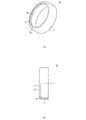
このようにして得られた中間加工体Mの底部10に対して周知の剪断加工(穴あけ加工)を施して不要部分を中抜きするようにカットして図1(a)(b)及び図16(c)のリング体15を得ることができる。リング体12は底部10をカットすることで内周に向かって張り出す浅いフランジ16が形成される。このフランジ16側の端部が接合金具とした際の挿入端部17とされる。
また、パンチの種類を変えることで例えば図2(a)(b)に示すような大きく張り出すフランジ18を有するリング体19を構成することもできる。
Next, a process of forming the intermediate workpiece M from the blank B by the punching device having such a configuration will be described.
As shown in FIG. 12, the blank B is set so as to close the hole 2 on the upper surface of the
Here, the punch 8 and the ram 4 are moved upward as the hydraulic device is controlled based on the position detection information of the position sensor. The ram 4 stops at the original position in FIG. On the other hand, since the intermediate workpiece M is stuck to the outer surface of the punch 8 without being released, the intermediate workpiece M is lifted above the
A known shearing process (drilling process) is performed on the bottom 10 of the intermediate workpiece M obtained in this way, and unnecessary parts are cut so as to be hollowed out. The
Further, by changing the type of punch, for example, a
次に上記のような工程で製造したリング体の具体的な実施例について説明する。
(実施例1)
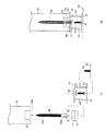
図5の接合金具21は図1(a)(b)に示すリング体15をリングジベル20として使用した一例である。接合金具21は縦長長方形形状の外観のベースプレート22と、ベースプレート22背面の左右方向中央位置において後方に延出される略長方形形状の挿入プレート23によって平面T字形状の基本骨格を構成している。ベースプレート22と挿入プレート23の上下方向長さは均等であり、ベースプレート22の幅に対して挿入プレート23は2.5倍程度の幅とされている。挿入プレート23はベースプレート22に対して溶接によって固着されている。ベースプレート22の前面には2つのリングジベル20(リング体15)が上下方向(縦方向)に間隔を空けて溶接によって固着されている。リングジベル20の外径はベースプレート22の幅と一致している。リングジベル20は挿入端部17側が前端となるように固着されている。
リングジベル20の中心位置にはベースプレート22を表裏に連通する透孔24が形成されている。挿入プレート23はベースプレート22の各透孔24に面した位置に左右方向に連通するアーチ状の切り欠き部25が形成されている。挿入プレート23の前端寄りには上下方向に沿った2カ所に左右方向に連通するピン孔26が形成されている。ピン孔26の上方には上方に開口したピン受け部27が形成されている。
Next, specific examples of the ring body manufactured by the above process will be described.
Example 1
5 is an example in which the
A through
次にこのような接合金具21を使用した柱28と梁29との接合構造の具体的な構築方法の一例について説明する。
まず、柱28に接合金具21を取り付ける。図6に示すように、柱28の当接面28aには接合金具21の取り付け位置に溝30が形成されている。溝30の中心位置には当接面28aからその裏面に当たる対向面28bにかけて第1の挿通孔31が形成されている。溝30はベースプレート22前面の2つのリングジベル20に対応した位置に上下二カ所に形成されている。溝30はちょうどリングジベル20の壁部11の厚さ及び長さと同寸に切削されている。
作業においては、まず、リングジベル20が溝30に挿嵌されるように接合金具21を柱28の当接面28aに仮止めする。リングジベル20は挿嵌状態で挿入端部17が溝30の奥側に配置されることとなる。そして、この状態で図5に示すように当接面28a側から各挿通孔31にボルト32を挿通させ、その先端にワッシャ33を介してナット34を螺合させる。
このように柱28に接合金具21を取り付けた状態で接合金具21を介して梁29を取り付ける。梁29の端部には接合金具21取り付け用の加工(仕口)が施され長手方向に沿ってスリット35が形成されている。またスリット35と直交して第2の挿通孔36が形成されている。このような梁29の端部側を上方から下降させて挿入プレート23を梁29のスリット35内に挿入させる。
このとき、梁29の最も上部の第2の挿通孔36aには前もってドリフトピン37を打ち込んでおく(挿嵌させておく)。これによって梁29の下降に伴ってドリフトピン37は挿入プレート23のピン受け部27上に載置されることとなる。そして、梁29の2段目以降の第2の挿通孔36はピン孔26と照合されるため、自動的に位置合わせが完了する。次いで図5に示すように、梁9の2段目以降の第2の挿通孔36に対してそれぞれドリフトピン37を打ち込むことで連結は完了する。
Next, an example of a specific construction method of the joint structure between the
First, the joining bracket 21 is attached to the
In the work, first, the joining fitting 21 is temporarily fixed to the
In this manner, the
At this time, the drift pin 37 is driven into (inserted into) the
この実施例1のような接合金具21を使用した柱28と梁29との接合構造では柱28に対して梁29が地震等によって剪断方向にずれるような外力(剪断力)が作用した場合にはリングジベル20には圧縮力が作用することとなるが、本実施の形態のリングジベル20では壁部11は大きく塑性変形させられ、かつ挿入端部17にはフランジ16が形成されているため従来のリングジベルに比べて圧縮方向の強度が高くなり、結果として従来よりも接合構造の自体の強度が向上することとなる。また、リングジベル20は柱28の溝30に挿嵌されてリングジベル20の内外において柱28に接することとなるため、剪断力はリングジベル20の内周側からも柱28に伝達されることとなり、剪断力を受けた際に力が集中しにくくバランスよく分散されることとなる。
In the joint structure of the
(実施例2)
図2(a)(b)は上記の工程において底部10をカットして大きく張り出すフランジ18を形成したリング体19である。そして、図7は図2(a)(b)に示すリング体15をリングジベル40として使用した接合金具41である。図7では上記実施例1の接合金具21とベースプレート22と挿入プレート23の構成は同じであるため、同じ番号を付して説明は省略する。リングジベル40は挿入端部17側が前端となるように固着されている。接合金具41は実施例1と同様に柱28と梁29を接合するために使用する。但し、実施例1では柱28にはリングジベル20を挿嵌するために溝30を形成したが、実施例2では柱28にリングジベル40の形状に一致する凹部を形成するようにする。
この実施例2のような接合金具41を使用した場合でも上記実施例1と同様に柱28に対して梁29が地震等によって剪断方向にずれるような外力(剪断力)が作用した場合にはリングジベル40には圧縮力が作用することとなるが、本実施の形態のリングジベル40は従来のリングジベルに比べて壁部11は大きく塑性変形させられ、かつ挿入端部17にはフランジ18が形成されているため、圧縮方向の強度が高くなり、結果として従来よりも接合構造の自体の強度が向上することとなる。
(Example 2)
2 (a) and 2 (b) show a
Even when the
(実施例3)
図3(a)(b)は図1(a)(b)に示すリング体15を挿入端部17側が互いに逆方向を向くように背中合わせに溶接して構成したリングジベル45である。そして、図8はこのようなリングジベル45を使用した接合構造の一例である。本実施例2では柱46及び梁47によって長方形に組まれた木造ラーメン構造において、連結箇所を斜めに筋交い48を配置した際の柱46と筋交い48の間にリングジベル45を配置している。尚、図8では下方側の接合状態のみ断面で図示しているが上方側も同様にリングジベル45で接合されているものとする。
柱46と筋交い48の接合面46a、48aにはそれぞれ同形状の第1の凹部49が形成されている。第1の凹部49はリング体15の外形形状に一致する。柱46と筋交い48には筋交い48の取り付け状態においてそれぞれ第1の凹部49の中心位置を水平に連通する挿通孔50が形成されている。柱46と筋交い48の接合面46a、48aと正対する裏面側であって挿通孔50が開口する位置は座ぐりされた第2の凹部51が形成されている。
このような構成の柱46に対して次のように筋交い48を固定する。まず、柱46と筋交い48の第1の凹部49内にリングジベル45を挿嵌して筋交い48を斜め状態に仮止めする。次いで第2の凹部51内にワッシャ52を配設した状態で柱46側から挿通孔50にボルト53を挿通させ、ワッシャ54を介してナット55を螺合させる。
このように柱46と筋交い48との間にリングジベル45を使用することで、従来よりもこの部分の接合構造の強度を向上させることができる。
(Example 3)
3 (a) and 3 (b) show a
A first concave portion 49 having the same shape is formed on each of the
The
Thus, by using the
(実施例4)
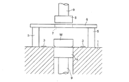
図4(a)〜(c)は図1(a)(b)に示すリング体15と図2(a)(b)に示すリング体19を挿入端部17側が互いに逆方向を向くように背中合わせに溶接して構成したリングジベル55である。そして、図11(a)(b)はこのようなリングジベル55を使用した接合構造の一例である。実施例4では基礎56上に固定された柱脚金物57上にリングジベル55を介在させて柱58を連結(接合)させるようにしている。図10に示すように、柱脚金物57は正方形形状の受け板60及びベース板61と、受け板60及びベース板61間に間隔を空けて配設された2枚の脚板62とから構成されている。受け板60の中央位置にはボルト挿通用の第1の透孔63が形成されている。ベース板61の中央位置には第2の透孔64が形成されている。図11(a)(b)に示すように、柱脚金物57は基礎56に埋設されたアンカーボルト65を第2の透孔64に挿通させた状態でナット67によって締結することで固定される。
図11(a)に示すように、柱57の下端面57aにはラグスクリューボルト69が埋設されている。図9(a)(b)に示すように、本実施例4で使用されるラグスクリューボルト69はラグスクリュー部69aとヘッド部69bとから構成されている。ラグスクリューボルト69にはヘッド部69bの内部には端部位置から長手方向に沿って雌ネジ部69cが形成されている。
柱58は基礎56上に固定された柱脚金物57に対して次のように連結される。柱58の下端面58aには埋設されたラグスクリューボルト69の周囲にリングジベル55の形状に対応した溝70が形成されている。図11(a)に示すように溝70内にリングジベル55の浅いフランジ16側の挿入端部17側を先端側として挿嵌する。この状態の柱58を柱脚金物57の受け板60上に立設し、第1の透孔63からワッシャ71を介してボルト72をラグスクリューボルト69の雌ネジ部60cに螺合させて締結することで固定する。
このように柱58と柱脚金物57との間にリングジベル55を使用することで、従来よりもこの部分の接合構造の強度を向上させることができる。また、リングジベル55は柱58の溝70に挿嵌されてリングジベル55の内外において柱58に接することとなるため、剪断力はリングジベル55の内周側からも柱58に伝達されることとなり、剪断力を受けた際に力が集中しにくくバランスよく分散されることとなる
Example 4
4 (a) to 4 (c) show the
As shown in FIG. 11A, a
The
In this way, by using the
尚、この発明は、次のように変更して具体化することも可能である。
・上記実施の形態のパンチング加工ではブランクBをダイ1側の穴2にブランクBを固定せずに成形する絞り加工を例として挙げたが、他のパンチング加工、例えばブランクBを固定した状態でパンチでブランクBを引き延ばして変形させる張り出し加工で中間加工体Mを成形するようにしてもよい。
・上記実施例1及び2の接合金具21、41は一例であって他の態様で実施するようにしてもよい。例えば、これら接合金具21、41におけるリングジベル20、40の数を2つ以外の数で構成するようにしてもよい。
・上記図2のリング体19を図3(a)(b)のように挿入端部17側が互いに逆方向を向くように背中合わせに溶接してリングジベルを構成するようにしてもよい。
・上記実施例4では柱脚金物57上に図4に示すリングジベル55を介在させて柱58を連結(接合)させるようにしていたが、柱脚金物57ではなく木質構造材である土台に柱を立設させる際に本発明のリングジベルを使用して連結するようにしてもよい。
その他本発明はその趣旨を逸脱しない態様で変更して実施することは自由である。
It should be noted that the present invention can be modified and embodied as follows.
In the punching process of the above embodiment, the drawing process for forming the blank B without fixing the blank B in the hole 2 on the
-The joining
The
In the fourth embodiment, the
In addition, the present invention can be freely modified and implemented without departing from the spirit of the present invention.
15、19…リング体、17…挿入端部、30、70…凹部としての溝、28、46、58…木質構造材としての柱、29…木質構造材としての梁、48…木質構造材としての筋交い、57…構造躯体としての柱脚金物、B…ブランク、M…中間加工体。
DESCRIPTION OF
Claims (10)
平板状のブランクをダイ上に載置し、パンチによって前記ブランクを前記ダイ側の穴に押し込むパンチング加工によって前記ブランクから円形の外周となる底部と同底部外周から立ち上がる円筒部とからなる円筒容器状の中間加工体を成形し、得られた前記中間加工体の前記底部を内側に張り出したフランジ状に肉を残して前後に連通させるように中抜きして前記挿入端部を形成するようにしたことを特徴とするリング体の製造方法。 It disposed at the junction between the coupling part or wood structural members with wooden structural member and the structural framework, embedded to insert the insertion end side of the axial end portion to the wooden structural material surface formed in the recess of the A method of manufacturing a ring body that is arranged and used as a joint fitting together with a bolt member and a nut member,
A cylindrical container shape comprising a bottom part that forms a circular outer periphery from the blank and a cylindrical part that rises from the outer periphery of the bottom by punching by placing a flat blank on the die and pressing the blank into the hole on the die side by punching The intermediate processed body was molded, and the bottom portion of the obtained intermediate processed body was hollowed out so as to leave the meat in a flange-like shape projecting inward and communicated back and forth to form the insertion end portion. A ring body manufacturing method characterized by the above.
Priority Applications (1)
| Application Number | Priority Date | Filing Date | Title |
|---|---|---|---|
| JP2016041695A JP6279637B2 (en) | 2016-03-04 | 2016-03-04 | Ring body manufacturing method, ring body, and joint metal fitting using ring body |
Applications Claiming Priority (1)
| Application Number | Priority Date | Filing Date | Title |
|---|---|---|---|
| JP2016041695A JP6279637B2 (en) | 2016-03-04 | 2016-03-04 | Ring body manufacturing method, ring body, and joint metal fitting using ring body |
Publications (2)
| Publication Number | Publication Date |
|---|---|
| JP2017154165A JP2017154165A (en) | 2017-09-07 |
| JP6279637B2 true JP6279637B2 (en) | 2018-02-14 |
Family
ID=59807687
Family Applications (1)
| Application Number | Title | Priority Date | Filing Date |
|---|---|---|---|
| JP2016041695A Active JP6279637B2 (en) | 2016-03-04 | 2016-03-04 | Ring body manufacturing method, ring body, and joint metal fitting using ring body |
Country Status (1)
| Country | Link |
|---|---|
| JP (1) | JP6279637B2 (en) |
Families Citing this family (3)
| Publication number | Priority date | Publication date | Assignee | Title |
|---|---|---|---|---|
| JP2020066955A (en) * | 2018-10-26 | 2020-04-30 | 株式会社エヌ・シー・エヌ | Method of burying lag screw bolt, and joint structure of structural skelton of wooden building and wooden building by the same |
| JP7236283B2 (en) * | 2019-02-12 | 2023-03-09 | 大成建設株式会社 | CLT panel |
| CN110773635B (en) * | 2019-10-16 | 2021-05-07 | 宁波金鼎紧固件有限公司 | Punch structure of hexagonal hole in adjustable thin-head hexagon socket head cap screw |
Family Cites Families (8)
| Publication number | Priority date | Publication date | Assignee | Title |
|---|---|---|---|---|
| JPH02105405U (en) * | 1988-11-07 | 1990-08-22 | ||
| JP2879919B2 (en) * | 1990-02-22 | 1999-04-05 | ミサワホーム株式会社 | Ties for the foundation and foundation of the house |
| JP3671760B2 (en) * | 1999-09-01 | 2005-07-13 | トヨタ自動車株式会社 | Ring member forming method and press machine |
| JP2001241108A (en) * | 2000-02-28 | 2001-09-04 | Shelter Co Ltd | Connecting hardware for wooden framework |
| JP2002137021A (en) * | 2000-10-30 | 2002-05-14 | Takagi Seisakusho:Kk | Method and machine for forming cup-shaped metal parts |
| JP2003247275A (en) * | 2002-02-22 | 2003-09-05 | Hakozaki:Kk | Framework structure for wooden building |
| JP2003328453A (en) * | 2002-05-14 | 2003-11-19 | Ncn:Kk | Joint metal element |
| JP2006124946A (en) * | 2004-10-26 | 2006-05-18 | Grand Form:Kk | Member fixture |
-
2016
- 2016-03-04 JP JP2016041695A patent/JP6279637B2/en active Active
Also Published As
| Publication number | Publication date |
|---|---|
| JP2017154165A (en) | 2017-09-07 |
Similar Documents
| Publication | Publication Date | Title |
|---|---|---|
| US3925875A (en) | Method of constructing a prefabricated wall module | |
| JP6279637B2 (en) | Ring body manufacturing method, ring body, and joint metal fitting using ring body | |
| CN103015536B (en) | Beam-column joint connecting device for multi-story/high-rise assembly type steel structure system | |
| TW201608087A (en) | Structure and method for joining column and beam | |
| JP4710067B2 (en) | Beam-column joint structure | |
| JP4649303B2 (en) | Pillar fasteners | |
| JP5834376B1 (en) | Construction method of wooden ramen structure | |
| JP4813874B2 (en) | Assembly method and assembly jig for pipe structure building | |
| JP6211723B1 (en) | Timber bonded structure | |
| JP4707158B1 (en) | Joining structure of hollow square material and bathroom unit installation table | |
| JP2006307568A (en) | Structure and method for joining beam and column together | |
| JP6934285B2 (en) | Wooden column beam joint structure | |
| JP7062463B2 (en) | Connection structure | |
| JP6421292B2 (en) | Wooden construction method | |
| JP3638054B2 (en) | Structural material joints for construction | |
| JP2010255227A (en) | Column-beam joint structure and reinforced concrete member | |
| JP2006274667A (en) | Member connection device | |
| KR102565855B1 (en) | Method for fixing stell bar using stell bar fixing apparatus | |
| JPH06129022A (en) | Joint member metallic material and building method and engineering method using the joint member metallic material | |
| JP7359355B1 (en) | Beam joining equipment for square steel pipe columns | |
| JP7175508B2 (en) | connector | |
| JP3115065U (en) | Assembled horizontal frame joint hardware | |
| KR102345645B1 (en) | Wooden pole for construction with inner hollow and manufacturing method thereof | |
| JP3111912U (en) | Shaft dowels and architectural fittings | |
| JP4726266B1 (en) | Hollow member joining structure and jig |
Legal Events
| Date | Code | Title | Description |
|---|---|---|---|
| A131 | Notification of reasons for refusal |
Free format text: JAPANESE INTERMEDIATE CODE: A131 Effective date: 20171004 |
|
| A711 | Notification of change in applicant |
Free format text: JAPANESE INTERMEDIATE CODE: A712 Effective date: 20171110 |
|
| A521 | Request for written amendment filed |
Free format text: JAPANESE INTERMEDIATE CODE: A523 Effective date: 20171115 |
|
| A521 | Request for written amendment filed |
Free format text: JAPANESE INTERMEDIATE CODE: A821 Effective date: 20171110 |
|
| TRDD | Decision of grant or rejection written | ||
| A01 | Written decision to grant a patent or to grant a registration (utility model) |
Free format text: JAPANESE INTERMEDIATE CODE: A01 Effective date: 20171227 |
|
| A61 | First payment of annual fees (during grant procedure) |
Free format text: JAPANESE INTERMEDIATE CODE: A61 Effective date: 20180117 |
|
| R150 | Certificate of patent or registration of utility model |
Ref document number: 6279637 Country of ref document: JP Free format text: JAPANESE INTERMEDIATE CODE: R150 |
|
| S531 | Written request for registration of change of domicile |
Free format text: JAPANESE INTERMEDIATE CODE: R313531 |
|
| R350 | Written notification of registration of transfer |
Free format text: JAPANESE INTERMEDIATE CODE: R350 |
|
| S111 | Request for change of ownership or part of ownership |
Free format text: JAPANESE INTERMEDIATE CODE: R313117 |
|
| R350 | Written notification of registration of transfer |
Free format text: JAPANESE INTERMEDIATE CODE: R350 |
|
| R250 | Receipt of annual fees |
Free format text: JAPANESE INTERMEDIATE CODE: R250 |
|
| R250 | Receipt of annual fees |
Free format text: JAPANESE INTERMEDIATE CODE: R250 |