JP6276838B2 - Seal molding system and method - Google Patents
Seal molding system and method Download PDFInfo
- Publication number
- JP6276838B2 JP6276838B2 JP2016500274A JP2016500274A JP6276838B2 JP 6276838 B2 JP6276838 B2 JP 6276838B2 JP 2016500274 A JP2016500274 A JP 2016500274A JP 2016500274 A JP2016500274 A JP 2016500274A JP 6276838 B2 JP6276838 B2 JP 6276838B2
- Authority
- JP
- Japan
- Prior art keywords
- mold
- fitting
- seal
- mold body
- panel
- Prior art date
- Legal status (The legal status is an assumption and is not a legal conclusion. Google has not performed a legal analysis and makes no representation as to the accuracy of the status listed.)
- Active
Links
- 238000000465 moulding Methods 0.000 title claims description 42
- 238000000034 method Methods 0.000 title description 48
- 239000000565 sealant Substances 0.000 claims description 94
- 238000007789 sealing Methods 0.000 claims description 45
- 230000000295 complement effect Effects 0.000 claims description 30
- 238000002347 injection Methods 0.000 claims description 21
- 239000007924 injection Substances 0.000 claims description 21
- 239000012528 membrane Substances 0.000 claims description 20
- 238000007599 discharging Methods 0.000 claims description 6
- 235000018936 Vitellaria paradoxa Nutrition 0.000 claims 2
- 238000009434 installation Methods 0.000 description 9
- 230000008878 coupling Effects 0.000 description 8
- 238000010168 coupling process Methods 0.000 description 8
- 238000005859 coupling reaction Methods 0.000 description 8
- 230000007246 mechanism Effects 0.000 description 8
- 239000000463 material Substances 0.000 description 7
- 238000005304 joining Methods 0.000 description 6
- 230000015572 biosynthetic process Effects 0.000 description 5
- 238000005192 partition Methods 0.000 description 5
- 239000000853 adhesive Substances 0.000 description 3
- 230000001070 adhesive effect Effects 0.000 description 3
- 230000013011 mating Effects 0.000 description 3
- 230000008569 process Effects 0.000 description 3
- 239000004677 Nylon Substances 0.000 description 2
- 229920006362 Teflon® Polymers 0.000 description 2
- 230000004888 barrier function Effects 0.000 description 2
- 239000003795 chemical substances by application Substances 0.000 description 2
- 239000012530 fluid Substances 0.000 description 2
- 230000006872 improvement Effects 0.000 description 2
- 239000000203 mixture Substances 0.000 description 2
- 239000012778 molding material Substances 0.000 description 2
- 229920001778 nylon Polymers 0.000 description 2
- 239000002861 polymer material Substances 0.000 description 2
- 229920001343 polytetrafluoroethylene Polymers 0.000 description 2
- 239000004810 polytetrafluoroethylene Substances 0.000 description 2
- 239000004590 silicone sealant Substances 0.000 description 2
- 239000004952 Polyamide Substances 0.000 description 1
- 239000004809 Teflon Substances 0.000 description 1
- 239000004699 Ultra-high molecular weight polyethylene Substances 0.000 description 1
- 230000000903 blocking effect Effects 0.000 description 1
- 230000015556 catabolic process Effects 0.000 description 1
- 229910010293 ceramic material Inorganic materials 0.000 description 1
- 238000007796 conventional method Methods 0.000 description 1
- 238000005260 corrosion Methods 0.000 description 1
- 230000007797 corrosion Effects 0.000 description 1
- 238000006731 degradation reaction Methods 0.000 description 1
- 239000000428 dust Substances 0.000 description 1
- 238000011065 in-situ storage Methods 0.000 description 1
- 229920001684 low density polyethylene Polymers 0.000 description 1
- 239000004702 low-density polyethylene Substances 0.000 description 1
- 239000000696 magnetic material Substances 0.000 description 1
- 230000005389 magnetism Effects 0.000 description 1
- 238000004519 manufacturing process Methods 0.000 description 1
- 239000007769 metal material Substances 0.000 description 1
- 230000004048 modification Effects 0.000 description 1
- 238000012986 modification Methods 0.000 description 1
- 239000006082 mold release agent Substances 0.000 description 1
- 230000035515 penetration Effects 0.000 description 1
- 230000002093 peripheral effect Effects 0.000 description 1
- 229920002647 polyamide Polymers 0.000 description 1
- 229920000642 polymer Polymers 0.000 description 1
- -1 polytetrafluoroethylene Polymers 0.000 description 1
- 238000003825 pressing Methods 0.000 description 1
- 239000012779 reinforcing material Substances 0.000 description 1
- 229920002631 room-temperature vulcanizate silicone Polymers 0.000 description 1
- 239000003351 stiffener Substances 0.000 description 1
- 229920000785 ultra high molecular weight polyethylene Polymers 0.000 description 1
- 238000004073 vulcanization Methods 0.000 description 1
Images


Classifications
-
- B—PERFORMING OPERATIONS; TRANSPORTING
- B29—WORKING OF PLASTICS; WORKING OF SUBSTANCES IN A PLASTIC STATE IN GENERAL
- B29C—SHAPING OR JOINING OF PLASTICS; SHAPING OF MATERIAL IN A PLASTIC STATE, NOT OTHERWISE PROVIDED FOR; AFTER-TREATMENT OF THE SHAPED PRODUCTS, e.g. REPAIRING
- B29C45/00—Injection moulding, i.e. forcing the required volume of moulding material through a nozzle into a closed mould; Apparatus therefor
- B29C45/14—Injection moulding, i.e. forcing the required volume of moulding material through a nozzle into a closed mould; Apparatus therefor incorporating preformed parts or layers, e.g. injection moulding around inserts or for coating articles
- B29C45/14336—Coating a portion of the article, e.g. the edge of the article
- B29C45/14426—Coating the end of wire-like or rod-like or cable-like or blade-like or belt-like articles
-
- B—PERFORMING OPERATIONS; TRANSPORTING
- B29—WORKING OF PLASTICS; WORKING OF SUBSTANCES IN A PLASTIC STATE IN GENERAL
- B29C—SHAPING OR JOINING OF PLASTICS; SHAPING OF MATERIAL IN A PLASTIC STATE, NOT OTHERWISE PROVIDED FOR; AFTER-TREATMENT OF THE SHAPED PRODUCTS, e.g. REPAIRING
- B29C33/00—Moulds or cores; Details thereof or accessories therefor
- B29C33/005—Moulds or cores; Details thereof or accessories therefor characterised by the location of the parting line of the mould parts
-
- B—PERFORMING OPERATIONS; TRANSPORTING
- B29—WORKING OF PLASTICS; WORKING OF SUBSTANCES IN A PLASTIC STATE IN GENERAL
- B29C—SHAPING OR JOINING OF PLASTICS; SHAPING OF MATERIAL IN A PLASTIC STATE, NOT OTHERWISE PROVIDED FOR; AFTER-TREATMENT OF THE SHAPED PRODUCTS, e.g. REPAIRING
- B29C33/00—Moulds or cores; Details thereof or accessories therefor
- B29C33/0077—Moulds or cores; Details thereof or accessories therefor characterised by the configuration of the mould filling gate ; accessories for connecting the mould filling gate with the filling spout
-
- B—PERFORMING OPERATIONS; TRANSPORTING
- B29—WORKING OF PLASTICS; WORKING OF SUBSTANCES IN A PLASTIC STATE IN GENERAL
- B29C—SHAPING OR JOINING OF PLASTICS; SHAPING OF MATERIAL IN A PLASTIC STATE, NOT OTHERWISE PROVIDED FOR; AFTER-TREATMENT OF THE SHAPED PRODUCTS, e.g. REPAIRING
- B29C39/00—Shaping by casting, i.e. introducing the moulding material into a mould or between confining surfaces without significant moulding pressure; Apparatus therefor
- B29C39/02—Shaping by casting, i.e. introducing the moulding material into a mould or between confining surfaces without significant moulding pressure; Apparatus therefor for making articles of definite length, i.e. discrete articles
- B29C39/10—Shaping by casting, i.e. introducing the moulding material into a mould or between confining surfaces without significant moulding pressure; Apparatus therefor for making articles of definite length, i.e. discrete articles incorporating preformed parts or layers, e.g. casting around inserts or for coating articles
-
- B—PERFORMING OPERATIONS; TRANSPORTING
- B29—WORKING OF PLASTICS; WORKING OF SUBSTANCES IN A PLASTIC STATE IN GENERAL
- B29C—SHAPING OR JOINING OF PLASTICS; SHAPING OF MATERIAL IN A PLASTIC STATE, NOT OTHERWISE PROVIDED FOR; AFTER-TREATMENT OF THE SHAPED PRODUCTS, e.g. REPAIRING
- B29C45/00—Injection moulding, i.e. forcing the required volume of moulding material through a nozzle into a closed mould; Apparatus therefor
- B29C45/14—Injection moulding, i.e. forcing the required volume of moulding material through a nozzle into a closed mould; Apparatus therefor incorporating preformed parts or layers, e.g. injection moulding around inserts or for coating articles
- B29C45/14549—Coating rod-like, wire-like or belt-like articles
-
- B—PERFORMING OPERATIONS; TRANSPORTING
- B29—WORKING OF PLASTICS; WORKING OF SUBSTANCES IN A PLASTIC STATE IN GENERAL
- B29C—SHAPING OR JOINING OF PLASTICS; SHAPING OF MATERIAL IN A PLASTIC STATE, NOT OTHERWISE PROVIDED FOR; AFTER-TREATMENT OF THE SHAPED PRODUCTS, e.g. REPAIRING
- B29C45/00—Injection moulding, i.e. forcing the required volume of moulding material through a nozzle into a closed mould; Apparatus therefor
- B29C45/14—Injection moulding, i.e. forcing the required volume of moulding material through a nozzle into a closed mould; Apparatus therefor incorporating preformed parts or layers, e.g. injection moulding around inserts or for coating articles
- B29C45/14598—Coating tubular articles
-
- B—PERFORMING OPERATIONS; TRANSPORTING
- B29—WORKING OF PLASTICS; WORKING OF SUBSTANCES IN A PLASTIC STATE IN GENERAL
- B29C—SHAPING OR JOINING OF PLASTICS; SHAPING OF MATERIAL IN A PLASTIC STATE, NOT OTHERWISE PROVIDED FOR; AFTER-TREATMENT OF THE SHAPED PRODUCTS, e.g. REPAIRING
- B29C45/00—Injection moulding, i.e. forcing the required volume of moulding material through a nozzle into a closed mould; Apparatus therefor
- B29C45/17—Component parts, details or accessories; Auxiliary operations
- B29C45/26—Moulds
- B29C45/34—Moulds having venting means
-
- B—PERFORMING OPERATIONS; TRANSPORTING
- B29—WORKING OF PLASTICS; WORKING OF SUBSTANCES IN A PLASTIC STATE IN GENERAL
- B29C—SHAPING OR JOINING OF PLASTICS; SHAPING OF MATERIAL IN A PLASTIC STATE, NOT OTHERWISE PROVIDED FOR; AFTER-TREATMENT OF THE SHAPED PRODUCTS, e.g. REPAIRING
- B29C45/00—Injection moulding, i.e. forcing the required volume of moulding material through a nozzle into a closed mould; Apparatus therefor
- B29C45/14—Injection moulding, i.e. forcing the required volume of moulding material through a nozzle into a closed mould; Apparatus therefor incorporating preformed parts or layers, e.g. injection moulding around inserts or for coating articles
- B29C45/14336—Coating a portion of the article, e.g. the edge of the article
- B29C2045/14459—Coating a portion of the article, e.g. the edge of the article injecting seal elements
-
- B—PERFORMING OPERATIONS; TRANSPORTING
- B29—WORKING OF PLASTICS; WORKING OF SUBSTANCES IN A PLASTIC STATE IN GENERAL
- B29C—SHAPING OR JOINING OF PLASTICS; SHAPING OF MATERIAL IN A PLASTIC STATE, NOT OTHERWISE PROVIDED FOR; AFTER-TREATMENT OF THE SHAPED PRODUCTS, e.g. REPAIRING
- B29C45/00—Injection moulding, i.e. forcing the required volume of moulding material through a nozzle into a closed mould; Apparatus therefor
- B29C45/17—Component parts, details or accessories; Auxiliary operations
- B29C45/64—Mould opening, closing or clamping devices
- B29C2045/645—Mould opening, closing or clamping devices using magnetic means
-
- B—PERFORMING OPERATIONS; TRANSPORTING
- B29—WORKING OF PLASTICS; WORKING OF SUBSTANCES IN A PLASTIC STATE IN GENERAL
- B29C—SHAPING OR JOINING OF PLASTICS; SHAPING OF MATERIAL IN A PLASTIC STATE, NOT OTHERWISE PROVIDED FOR; AFTER-TREATMENT OF THE SHAPED PRODUCTS, e.g. REPAIRING
- B29C33/00—Moulds or cores; Details thereof or accessories therefor
- B29C33/30—Mounting, exchanging or centering
-
- B—PERFORMING OPERATIONS; TRANSPORTING
- B29—WORKING OF PLASTICS; WORKING OF SUBSTANCES IN A PLASTIC STATE IN GENERAL
- B29C—SHAPING OR JOINING OF PLASTICS; SHAPING OF MATERIAL IN A PLASTIC STATE, NOT OTHERWISE PROVIDED FOR; AFTER-TREATMENT OF THE SHAPED PRODUCTS, e.g. REPAIRING
- B29C45/00—Injection moulding, i.e. forcing the required volume of moulding material through a nozzle into a closed mould; Apparatus therefor
- B29C45/17—Component parts, details or accessories; Auxiliary operations
- B29C45/64—Mould opening, closing or clamping devices
- B29C45/641—Clamping devices using means for straddling or interconnecting the mould halves, e.g. jaws, straps, latches
-
- B—PERFORMING OPERATIONS; TRANSPORTING
- B29—WORKING OF PLASTICS; WORKING OF SUBSTANCES IN A PLASTIC STATE IN GENERAL
- B29L—INDEXING SCHEME ASSOCIATED WITH SUBCLASS B29C, RELATING TO PARTICULAR ARTICLES
- B29L2023/00—Tubular articles
-
- B—PERFORMING OPERATIONS; TRANSPORTING
- B29—WORKING OF PLASTICS; WORKING OF SUBSTANCES IN A PLASTIC STATE IN GENERAL
- B29L—INDEXING SCHEME ASSOCIATED WITH SUBCLASS B29C, RELATING TO PARTICULAR ARTICLES
- B29L2031/00—Other particular articles
- B29L2031/26—Sealing devices, e.g. packaging for pistons or pipe joints
-
- B—PERFORMING OPERATIONS; TRANSPORTING
- B29—WORKING OF PLASTICS; WORKING OF SUBSTANCES IN A PLASTIC STATE IN GENERAL
- B29L—INDEXING SCHEME ASSOCIATED WITH SUBCLASS B29C, RELATING TO PARTICULAR ARTICLES
- B29L2031/00—Other particular articles
- B29L2031/30—Vehicles, e.g. ships or aircraft, or body parts thereof
- B29L2031/3076—Aircrafts
Description
電気コネクタは、航空機全体の多くの場所に設置されている。電気コネクタは、航空機の隔壁に形成された穴に通すことによって、パネルや隔壁に取り付けることがある。例えば、機械式の留め具を用いてコネクタフランジを隔壁に取り付けることによって、電気コネクタを、隔壁に固定する場合がある。ある種の電気コネクタ設置箇所においては、コネクタフランジ全体及び機械式留め具をシールで包囲することによって、流体が隔壁を通るのを防ぐためのバリアーを設けたり、コネクタ及び隔壁を腐食から保護したりする必要がある。 Electrical connectors are installed at many locations throughout the aircraft. The electrical connector may be attached to the panel or bulkhead by passing it through a hole formed in the bulkhead of the aircraft. For example, the electrical connector may be fixed to the partition wall by attaching a connector flange to the partition wall using a mechanical fastener. At certain electrical connector locations, the entire connector flange and mechanical fasteners are enclosed with seals to provide a barrier to prevent fluid from passing through the septum, and to protect the connector and septum from corrosion. There is a need to.
電気コネクタを隔壁に対してシールするための従来の方法は、手工具を用いてコネクタフランジ及び機械式留め具の周りに手作業でシーラントを付けることを含んでいる。残念なことに、シーラントを手作業で付けるプロセスは、面倒で時間がかかり、コネクタの取り付け箇所によって不均一を生じさせるものである。加えて、シーラントを手作業で付けると、一般的に表面仕上げが粗くなり、製品の見掛け品質(perceived quality)及び/又は実際の品質の低下につながる。また、表面仕上げが、カール(curl)、空隙、又はその他の表面特異部が原因で水分を保持する傾向があると判断されると、シールを再加工又は除去し、手作業でシーラントを付け直す必要が生じる場合があり、これはプロセスフローにマイナスの影響を与える。 Conventional methods for sealing an electrical connector against a septum include manually applying sealant around the connector flange and mechanical fastener using a hand tool. Unfortunately, the process of manually applying the sealant is cumbersome and time consuming, and causes non-uniformity depending on where the connector is attached. In addition, manually applying the sealant generally results in a rough surface finish, leading to a perceived quality and / or actual quality degradation of the product. Also, if the surface finish is determined to tend to retain moisture due to curl, voids, or other surface-specific features, the seal is reworked or removed and the sealant is re-applied manually. This may have a negative impact on the process flow.
これらからわかるように、時間効率よくコネクタフランジにシールを形成するためのシステム及び方法が、当技術分野で必要とされている。また、当技術分野においては、複数のコネクタ設置箇所で同じように高品質で滑らかな表面仕上げを実現することができるシールの形成システム及び方法が必要とされている。 As can be seen, there is a need in the art for systems and methods for forming seals on connector flanges in a time efficient manner. There is also a need in the art for a seal formation system and method that can achieve a similarly high quality and smooth surface finish at multiple connector locations.
シール形成に関連する上述した問題は、特に本開示によって、対処及び緩和される。本開示は、フィッティングのフィッティング外側輪郭面と補完し合うように形成されたモールド内側輪郭面を有するモールド体を含むシール成形システムを提供するものである。モールド体は、パネル表面と補完し合うように形成されたモールド基部を有する。モールド体は、モールドキャビティにシーラントを注入するための注入口、及び、空気及びシーラントをモールドキャビティから排出するための排出口を含む。 The above-mentioned problems associated with seal formation are addressed and mitigated, particularly by the present disclosure. The present disclosure provides a seal molding system that includes a mold body having a mold inner contour surface that is shaped to complement the fitting outer contour surface of the fitting. The mold body has a mold base formed so as to complement the panel surface. The mold body includes an inlet for injecting a sealant into the mold cavity and an outlet for discharging air and the sealant from the mold cavity.
さらなる実施形態において、開示のシール成形システムは、電気コネクタのフィッティング外側輪郭面と補完し合うように形成されたモールド内側輪郭面及びモールドボアを有するモールド体を含む。モールド体は、フィッティングフランジ及びパネル表面と補完し合うように形成されたモールド基部を有する。モールド体は、モールド内側輪郭面及びフィッティング外側輪郭面によって少なくとも一部が規定されたモールドキャビティにシーラントを注入するための注入口を含む。モールド体は、空気及びシーラントをモールドキャビティから排出するための排出口をさらに含む。 In a further embodiment, the disclosed seal molding system includes a mold body having a mold inner contour surface and a mold bore formed to complement the fitting outer contour surface of the electrical connector. The mold body has a mold base formed so as to complement the fitting flange and the panel surface. The mold body includes an inlet for injecting sealant into a mold cavity defined at least in part by a mold inner contour surface and a fitting outer contour surface. The mold body further includes a discharge port for discharging air and sealant from the mold cavity.
パネルに取り付けられたフィッティングの周りにシールを形成する方法も開示される。当該方法は、パネルに取り付けられたフィッティングのフィッティング外側輪郭面と補完し合うように形成されたモールド内側輪郭面を有するモールド体を用意することを含む。当該方法は、さらに、モールド体をフィッティングに取り付けることと、モールド体に形成された注入口に、モールド内側輪郭面及びフィッティング外側輪郭面によって包囲されたモールドキャビティをシーラントが実質的に満たすまで、シーラントを注入すること、とをさらに含む。シーラントを硬化させ、その後にフィッティングからモールド体を取り外すことができる。 A method of forming a seal around a fitting attached to a panel is also disclosed. The method includes providing a mold body having a mold inner contour surface formed to complement a fitting outer contour surface of a fitting attached to a panel. The method further includes attaching the mold body to the fitting and sealing the sealant until the sealant substantially fills the mold cavity surrounded by the mold inner contour surface and the fitting outer contour surface at the inlet formed in the mold body. And injecting. The sealant can be cured and then the mold body can be removed from the fitting.
上述した特徴、機能、利点は、本願の開示の様々な実施形態によって個別に達成することができ、あるいは、さらに他の実施形態と組み合わせてもよく、そのさらなる詳細は、以下の記載及び図面を参照することによってより明らかになるものである。 The features, functions, and advantages described above can be achieved individually by the various embodiments of the present disclosure, or may be combined with still other embodiments, the details of which are set forth in the following description and drawings. It will become clearer by reference.
本開示のこれらの特徴及びその他の特徴は、図面を参照することによってより明らかになるだろう。これらの図面全体において、同様の部品については同様の数字で示している。
本開示の好ましい様々な実施形態を例示する目的で示した図面を参照すると、図1は航空機100の斜視図であり、当該航空機は、航空機100の前端から航空機100の後端まで延びる胴体102を有する。後端は、航空機100の方向制御のための1つ又は複数の尾翼面を有する尾翼104を含む。航空機100は、さらに、胴体102から外側に延びる一対の主翼106、及び、パイロン又は支柱を用いて主翼106に取り付けられた1つ又は複数の推進装置108を含む。
Referring to the drawings presented for purposes of illustrating various preferred embodiments of the present disclosure, FIG. 1 is a perspective view of an
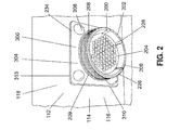
図2は、航空機100のパネル114(例えば隔壁112)におけるフィッティング200の設置箇所(例えば電気コネクタ202の設置箇所)を示す。パネル114は、フィッティング200のフロント部206を通すための開口又は穴(図示せず)を含む。フィッティング200は、複数のフランジ留め具234を用いてパネル114に取り付け可能なフィッティングフランジ232によって、パネル114に固定することができる。フィッティング200のフロント部206は、対応するコネクタ(図示せず)と連結するためのコネクタプラグ204を収容する。一実施形態において、フィッティング200のフロント部206は、対応するコネクタを螺合するためのねじ切り部208を有する。フィッティング200は、ねじ切り部208とパネル114との間に位置する非ねじ切り部209も有する。
FIG. 2 shows an installation location of the fitting 200 (eg, an installation location of the electrical connector 202) on the panel 114 (eg, the bulkhead 112) of the
図2において、フィッティング200、フィッティングフランジ232、フランジ留め具234、及び隣接するパネル表面116は、好都合なことに、高品質で形状合致するシール300で包囲される。好都合なことに、シール300は、本明細書に開示の省力化されたシステム及び方法を用いることによって、その場で成形され、滑らかな表面を有する。シール成形システム400は、1つ又は複数のモールド体402を用い、当該モールド体は、フィッティング200の周りの適所でパネル表面116に対してクランプされる。モールド体402に形成された注入口420に、例えばシーラントガン(sealant gun)(図示せず)を用いて、シーラント316を注入することができる。モールド体402の反対側に位置する排出口422からシーラント316が流れ出るまで、モールドキャビティ416にシーラント316を連続的に注入する。シーラント316を硬化させた後、モールド体402を取り除いて、シール300を露出させる。例えばスクレーパー(scraper)(図示せず)を用いて、シール300からバリ(図示せず)を取り除く。
In FIG. 2, the fitting 200, the
本明細書に開示のシール成形システム400及び方法は、パネル取り付けフィッティングをシールするための労力を、手作業によってシールする方法の労力に比べて、大幅に減らすことができるため、有利である。例えば、シール成形システム400は、パネル114に対してフィッティング200をシールする手作業のシステムに比べて、90%以上の省力化を実現することができる。また、シール成形システム400及び方法は、手作業によるシール方法に比べて、製品の実際の品質及び見掛け品質を、大幅に改善することができる。例えば、シール成形システム400は、複数のフィッティング設置箇所で同じように再現できる滑らかな表面仕上げのシール300を実現することができ、また、手作業による方法の場合の表面仕上げに対して大幅な改善をもたらすことができる。シール成形システム400を用いて、パネルに設けられた穴(図示せず)、例えば、管状フィッティング(図示せず)用の穴や、要素や物品(図示せず)がフィッティング無しで隔壁又はパネルを貫通している箇所、の周りにシール300を成形することもできる。例えば、シール成形システム400を用いることによって、圧力隔壁を通る1つ又は複数のワイヤーの束(図示せず)用に設けられた、フィッティングのない貫通箇所(図示せず)の周りに、シール(図示せず)を成形することができる。このような箇所に、グロメット(図示せず)を取り付けてもよい。シール成形システム400をワイヤー束の周りに組み付け、ワイヤー束の周囲及び個々のワイヤー(図示せず)の間にシーラントを注入することによって、シールを形成することができる。
The
図3は、図2のフィッティング200設置箇所のバック側120を示している。図示の実施形態において、フィッティング200は、フィッティング200に収容されたコネクタプラグ204から延びるケーブル又はワイヤーの束214に対するひずみ解放(strain relief)を行うためのバックシェル(backshell)212含む。バックシェル212は、フィッティング200に対してワイヤー束214を固定配置するためのケーブルクランプ216を含む。フィッティング200は、パネルフロント側118又はパネルバック側120に取り付けられるフィッティングフランジ232を含む。フィッティングフランジ232は、フランジ留め具234を用いてパネル114に取り付けられ、フランジ留め具はシール300によって包囲される。フィッティングフランジ232も、フィッティング本体部226の周囲を囲み、パネル表面116に対して封止するシール300によって、包囲される。
FIG. 3 shows the
図4は、パネル114に取り付けられたフィッティング200の一実施形態の側面図である。フロント側シール部304が、フィッティング本体部226のパネル114に隣接する部分、フィッティングフランジ232をパネル114のバック側120に固定しているフランジ留め具234のヘッド部、及び、パネル表面116のフランジ留め具234に隣接する領域を包囲している。バックシェルシール部302も、フィッティング本体部226のパネル114に隣接する部分、フィッティングフランジ232、フランジ留め具234の突出端部、及び、パネル表面116のフランジ留め具234に隣接する領域を包囲している。本明細書に開示のシール成形システム400及び方法は、シール300の肉厚306を調整するための手段を提供し、また、パネル114のフロント側118及びバック側120でのパネル表面116に対するシール300の重なり量を調整するための手段も提供するため、有利である。
FIG. 4 is a side view of one embodiment of the fitting 200 attached to the
図5は、図4のフィッティング200の設置箇所の端面図であり、フロント側シール部304の外周部を示している。フロント側シール部304は、1つ又は複数のフランジ留め具234を取り囲むように構成されている。シール300の外周部は、正方形又は矩形状を有するものとして示しているが、本明細書に開示のシール成形システム400及び方法においては、フロント側118又はバック側120のシール300は、限定することなく任意のサイズ、形状及び構成で設けることができる。例えば、シール形成システム400で採用されるモールド体402は、円形又は他の外形を有するシール300を形成するように構成してもよい。
FIG. 5 is an end view of the installation location of the fitting 200 of FIG. 4 and shows the outer peripheral portion of the front
図6〜図9は、フィッティング200の周囲に組み付けるように構成された複数のモールド体部分440によって構成されるモールド体402の実施形態を示す。フィッティング200の周りに一体型のモールド体402を取り付けることが不可能もしくは望ましくない場合に、モールド体部分440を用いて、フィッティング200の周りにシール300を形成することができる。図示の実施形態において、モールド体402は、一対のモールド半体444を含む。モールド半体444は、バックシェルモールドアセンブリ454を形成するものとして示されており、バックシェルモールドアセンブリは、パネル114のバック側120で、フィッティング200の周りに組み付けられるように構成されるものである。一実施形態において、バックシェルモールドアセンブリ454のモールド半体444は、以下に説明するように製造を容易にするため、互いの鏡像体として形成される。
6-9 illustrate an embodiment of a
図6〜図7において、モールド体部分440は、モールド半体444として示されており、フィッティング200の周りに組み付けられた時にモールド体部分440同士を連結するための噛み合い部446を含んでいる。噛み合い部446は、モールド体部分440のそれぞれの周方向端部に形成又は成形されている。図示の構成においては、噛み合い部446は、タブ‐ポケット構造448を含む。タブ‐ポケット構造448は、各モールド半体444の周方向両端に、互いの鏡像体として、形成されている。これに代わる例として、図8〜図9は、噛み合い部446を有しない鏡像モールド体部分440を示している。
6-7, the
図10〜図12は、モールド体402のモールド内側輪郭面404を示している。図10は、一方のモールド半体444の下側を示しており、モールド基部406のモールド内側輪郭面404を示している。モールド内側輪郭面404は、フランジ留め具234を収容するための複数の凹部418を含んでいる。図11は、組み合わされたモールド体部分440の上面図であり、凹部418の配置を示している。注入口420及び排出口422も示されており、これらは、組み合わされたモールド体402の両側に形成されている。注入口420からシーラント316がモールドキャビティ416内に導入される。以下に説明するように、空気314及び余分なシーラント316は、排出口422を通って、モールドキャビティ416から逃がすことができる。
10 to 12 show a mold
図12は、組み合わされたモールド体402及び凹部418の配置を示す断面図である。また、モールド体402の一方側に設けられた注入口420とモールド体402の反対側に設けられた排出口422の配置も示されており、これらは、モールドキャビティ416の一方側からモールドキャビティ416の反対側へのシーラント316(図20)の流動を促進し、これによって、実質的にモールドキャビティ416から空気314を追い出し、モールドキャビティ416をシーラント316で完全に満たすことができる。このように注入口420及び排出口422を設けることによって、硬化されたシール300内に空隙又は気泡が発生するのを防ぐことができる。ただし、注入口420及び排出口422は、互いに対してモールド体402のどの位置に設けてもよく、モールド体402の両側に設けることに限定されない。また、モールド体402は、1つの注入口420及び1つの排出口422に限定されず、注入口420及び排出口422をいくつ含んでいてもよい。
FIG. 12 is a cross-sectional view showing the arrangement of the combined
図12において、モールド体402は、パネル表面116と係合する外縁部408を有するモールド基部406を含む。外縁部409は、モールド体402のモールド内側輪郭面404に、アール状エッジ部409が設けられている。図2〜図3に示すように、アール状エッジ部409は、シール300の外縁部310周りにシール用肉盛り(seal fillet)313(図2〜図3)を形成する。シール用肉盛り313によってパネル表面116と接触するシール外縁部310の表面積が増加し、これによって、シール300の完全性とシール力を向上させることができるため、好都合である。
In FIG. 12, the
図13は、組み合わされたモールド体402及びモールド内側輪郭面404の構成の断面図である。本明細書に開示の実施形態のいずれにおいても、モールド体402は、フィッティング本体226の周りに延びるように構成されたモールドフランジ410を含みうる。モールドフランジ410は、フィッティング200のフィッティング外側輪郭面228と補完し合うように形成されたモールドボア(mold bore)412を規定している。複数のモールド体部分440のアセンブリとして形成されたモールド体においては、モールド体部分440のそれぞれが、ボア部442を有する。これらボア部442同士が組み合わされると、フィッティング本体部226と補完し合う寸法及び形状とされたモールドボア412が形成される。
FIG. 13 is a cross-sectional view of the configuration of the combined
本明細書に開示のモールド体402の実施形態のいずれにおいても、モールドボア412は、任意の構成として、フィッティング本体部226の側面に対してシールするための径方向リップ部(radial lip)414を含みうる。本明細書に開示の実施形態のいずれにおいても、モールド体402は、パネル表面116と補完し合うように形成されたモールド基部406も含みうる。例えば、モールド基部406は、略フラットなパネル表面116とシール係合するための略フラットな形状を有する。ただし、モールド基部406は、湾曲形状又は特異形状を有するパネル表面(図示せず)とシール係合するための、湾曲又は特異形状(図示せず)を有するものとしてもよい。さらに、モールド体402は、モールドキャビティ416の側壁に抜き勾配424を有することによって、シール300の硬化後にシール300からモールド体402を外しやすくなっている。
In any of the embodiments of the
図14は、一体型構造として構成されたフロント側モールド450の一実施形態を示している。フロント側モールド450は、パネル114のフロント側118で、フィッティング200に連結されるものとして示されている。図14における一体型のモールド体402は、上述し且つ図6〜図13に示した、組み合わされたモールド体402と同様に構成することができる。モールド体402は、シール300の注入を容易にするための注入口420、及び、モールドキャビティ416を含む。排出口422によってモールドキャビティ416から空気314を逃すことができ、これによって、上述したようにシール300における空隙の形成を最小限に抑えることができる。
FIG. 14 shows one embodiment of a
図15は、モールド体402の端面図であり、モールド体402の両側における注入口420と排出口422との相対位置を示している。図16は、フロント側モールド450としての使用のために実施可能な一体型モールド体402の断面図であり、フィッティング本体部226と係合するための径方向リップ部414を示すとともに、注入口420及び排出口422の配置を示している。図17は、モールド体402の断面図であり、上述したように、フランジ留め具234を収容するための凹部418の配置を示している。モールド基部に抜き勾配424を形成することによって、シール300からモールド体402が外しやすくなっている。図16及び図17において、外縁部409は、モールド内側輪郭面404にアール状エッジ部409を有することによって、上述したように、シール300の外縁部310の周りにシール用肉盛り313(図2〜図3)が形成されるようになっている。
FIG. 15 is an end view of the
図18は、パネル114に取り付けられたフィッティング200の周りに組み付けられた一対のモールド体402の側面図である。モールド体402は、フロント側モールド450と、バックシェルモールドアセンブリ454とを含む。上記で示唆したように、バックシェルモールドアセンブリ454は、フィッティング200のに組み付けられた1つ又は複数のモールド体部分440によって構成されている。フロント側モールド450は一体型構造として示しているが、当該フロント側モールドも、パネル114のフロント側118において、フィッティング200に互いに噛み合わせた一対のモールド半体444などの、複数のモールド体部分440によって構成してもよい。本明細書に記載の実施形態のいずれにおいても、モールド体402は、所定のフィッティング(例えばコネクタ)のサイズ及び形状に合わせて設計及び製造することができる。また、各モールド体402は、フィッティング設置箇所の所定の側(すなわち、パネルフロント側110又はパネルバック側120)に取り付けるように構成することができる。
FIG. 18 is a side view of a pair of
図6〜図17において、モールド体402又はモールド体部分440は、高分子成形材料などの成形材料によって形成することができる。例えば、モールド体402は、ポリテトラフルオロエチレン(PTFE)すなわちテフロン(登録商標)によって形成してもよく、当該材料は、硬化後にシール300からモールド体402を取り外すための離型剤を必要とすることなく、シール300のなめらかな表面仕上げを実現することができるため、有利である。これに代えて、モールド体402は、ナイロン(登録商標)などの合成ポリアミド材料によって形成してもよく、この場合は、シール300の硬化後のモールド体402の取り外しに離型剤の使用が必要である。ナイロン(登録商標)のモールド体402の表面仕上げは、テフロン(登録商標)のモールド体402の表面仕上げほど好ましくないかもしれない。別の実施形態において、モールド体402は、超高分子量ポリエチレンによって形成してもよく、これは比較的低コストで提供することができるため、有利である。また、モールド体402は、低密度ポリエチレン又は他の高分子材料によって形成してもよい。ただし、モールド体402は、いかなる材料で形成してもよく、高分子材料に限定されない。例えば、モールド体402は、金属材料、セラミック材料、又は他の様々な材料のうちの任意の1つ又はこれらの組み合わせによって形成してもよい。
6 to 17, the
図19は、フィッティング200及びパネル114に取り付けられたフロント側モールド450の端面図である。フロント側モールド450の径方向リップ部414は、フィッティング200のフロント部206にシール係合するように構成されている。モールド体402は、径方向リップ部414が、フィッティング200の非ねじ切り部209に係合するように構成されている。同様に、バックシェルモールドアセンブリ454の径方向リップ部414も、フィッティング200のバック部210の非ねじ切り部209にシール係合するように構成されている。例えば、バックシェルモールドアセンブリ454の径方向リップ部414は、フィッティング隆起部218とパネル114との間に配置されている。本明細書に開示した実施形態のいずれにおいても、径方向リップ部414を省くことができ、モールドボア412は、フィッティング200の任意の部分と係合することによってモールドキャビティ416を封止する構成としてもよい。
FIG. 19 is an end view of the
図20は、フィッティング200及びパネル114に組み付けられたモールド体402の断面図である。フロント側モールド450のモールドキャビティ416は、パネル表面116、モールド内側輪郭面404、及びフィッティング外側輪郭面228によって規定又は包囲されている。図20は、フロント側モールド450の注入口420へのシーラント316の注入の様子を示している。シーラント316は、1成分シーラント(one-part sealant)でも2成分シーラント(two-part sealant)でもよい。例えば、1成分シーラントは、例えばRTVシリコーンシーラントなどの室温加硫(RTV)シーラントであってよく、シーラント316は、様々な組成のうちの任意のものであってもよい。2成分シーラントは、モールドキャビティ416への注入の前に混合される。シーラント316(例えば1成分又は2成分シーラント316)は、加圧下でシーラント316を注入するためのシーラントガンの使用などによって、モールドキャビティ416に注入される。注入されたシーラント316は、空気314を押しのけ、当該空気が1つ又は複数の排出口422から排出される。シーラント316が排出口422から流出し始めるまで、シーラント316は注入口420に連続的に注入される。シーラントの流出は、モールドキャビティ416が実質的にシーラント316で満たされたことを示唆する。
FIG. 20 is a cross-sectional view of the
図21は、フィッティング200の周りに取り付けられて、パネル114と係合しているバックシェルモールドアセンブリ454の端面図である。上記で示唆したように、バックシェルモールドアセンブリ454の径方向リップ部414は、フィッティング200のバック部210に、例えば非ねじ切り部209に沿ってシール係合するように構成されている。ただし、径方向リップ部414は省くことができ、モールド体402は、モールドボア412を適切に構成することによって、フィッティング200にシール係合し、モールドキャビティ416を封止することができる。
FIG. 21 is an end view of the
図22は、フィッティング200の周りに取り付けられ、パネル114と係合しているバックシェルモールドアセンブリ454の断面図である。モールドキャビティ416は、パネル表面116、モールド内側輪郭面404、及び、フィッティングフランジ232及びフランジ留め具234を含むフィッティング外側輪郭面228によって、規定又は包囲されている。図22は、さらに、バックシェルモールドアセンブリ454の注入口420へのシーラント316の注入、及び、排出口422からの空気314及び/又はシーラント316の排出の様子を示している。
FIG. 22 is a cross-sectional view of
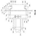
図23は、1つ又は複数のストラップ(strap)560を用いてフィッティング200及びパネル114にクランプされたフロント側モールド450及びバックシェルモールドアセンブリ454の側面図である。一実施形態において、ストラップ560は、パネル114のフロント側118及びバック側120にモールド体402を固定するためにきつく締められたタイラップ(tie wraps)562を含む。1つ又は複数の補強材564を、バックシェルモールドアセンブリ454の外側端部に設けることによって、バックシェルモールドアセンブリ454が均一なクランプ圧力にてパネル114に押し付けられるようになっている。補強材(図示せず)をフロント側モールド450にも設けてもよい。図示していないが、1つ又は複数のストラップ560(例えば、タイラップ562)を、バックシェルモールドアセンブリ454を形成しているモールド体部分440(例えばモールド半体444)の外側輪郭面の周りに締め付けることによって、シーラント316の注入及び硬化の間、モールド体部分440同士を連結させておいてもよい。さらなる実施形態において、フィッティング200のフロント部206に取り付けられた回転部材(図示せず)を用いて、フロント側モールド450をパネル表面116に対して固定又はクランプしてもよい。回転部材は、例えば、パネルナット(panel nut)、ダストキャップ、又は、パネル114のフロント側118から突出するフィッティング本体部226のねじ切り部208と螺合する他のねじ切り部材を含む。
FIG. 23 is a side view of the
図24は、モールド体部分440をパネル表面116に対してクランプするために実施することができるクランプ機構566の一実施形態を示す。クランプ機構566は、長状部材に取り付けられたクランプパッド(clamp pad)570を有する機械式クランプを含む。クランプパッド570の少なくとも1つを当該長状部材に沿って移動可能とすることにより、クランプパッド570間の間隔を調整するための手段が提供される。
FIG. 24 illustrates one embodiment of a
図25は、動作中のクランプ機構566を示している。クランプパッド570同士の間隔は、パネル114のフロント側118及びバック側120にわたるモールド体402の長さに一致するように調整することができる。クランプパッド570の一方又は両方がパッドフィッティング568を有することによって、クランプパッド570は旋回可能となり、モールド体402のいかなる角度ずれに対しても対応できるようになっている。このようにして、クランプ機構566は、モールド体402の縁部とパネル表面116との間にシーラント316が漏れ出ることがないように、モールド体402をパネル表面116に対して非偏心的にクランプする。モールド体部分440同士をクランプした後、シーラント316を注入口420に注入し、硬化させる。
FIG. 25 shows the
図26は、パネル114に対してモールド体402をクランプするための磁気連結システム540を示している。磁気連結システム540は、モールド体402に固定連結された少なくとも1つの磁石542を有しており、当該磁石は、モールド体402をパネル表面116に対して付勢するためのものである。ただし、各モールド体402が複数の磁石542を含んでいてもよい。例えば、各モールド体402が、当該モールド体402の両側に取り付けられた一対の磁石542を有することによって、均等な圧力でモールド体402をパネル表面116に対してクランプすることができる。一実施形態において、モールド体402は、モールド体402から外側に伸張する少なくとも1つの磁石支柱452を含む。磁石542は、これに対応する数の磁石穴544を有し、これに磁石支柱452を挿入することによって、磁石542をモールド体402に着脱可能に連結することができる。
FIG. 26 shows a
図27は、磁気連結システム540のさらなる実施形態を示しており、当該システムは、モールド体402の周りにクランプされるように構成されたクランプ546を含む。クランプ546は、クランプ留め具550によって互いに対して機械的に固定され且つフィッティング200の周りに組み付けられた一対のクランプ半体を含む。クランプ546は、モールド体402の周りに滑り嵌め状にクランプさせてもよいし、モールド体402の周りに非滑り嵌め状にクランプさせてもよい。1つ又は複数の磁石542が、クランプ546に対して、例えばクランプ546の下面に、機械的に固定されるか、又は接着により接合されている。クランプ546は、磁石542を支持することに加えて、モールド体402の周りにモールド体部分440(例えばモールド半体444)を固定するための装置としての機能も果たす。これに代えて、クランプ546を磁気引き付け可能な材料によって形成し、磁気によって磁石542をクランプ546に連結してもよい。さらに、クランプ546と磁石542を、磁性材料によって一体物(図示せず)として形成し、これを着脱可能にモールド体402に連結してもよい。クランプ546は、モールド体402の注入口420と整列するクランプ側注入口548を有することによって、シーラント316をモールドキャビティ416に注入できるようになっている。
FIG. 27 illustrates a further embodiment of a
図28は、モールド体402をパネル114に対して付勢する磁気連結システム540の側面図である。パネル114のフロント側118では、磁石542が、モールド体402から外側に伸張する磁石支柱452と係合している。パネル114のバック側120では、非滑り嵌め状にモールド体402に着脱可能にクランプされたクランプ546に対して、磁石542が、機械的に及び/又は接着により接合されている。これに代えて、クランプ546は、モールド体402の周りに滑り嵌めを形成して、モールド体402が段差部(図示せず)を有することによって、磁石542の磁気連結によって、クランプ546がモールド体402をパネル144に対して付勢する構成としてもよい。図28において、パネル114のフロント側118の1つ又は複数の磁石542が、パネル114のバック側120の1つ又は複数の磁石542と磁気的に連結するように構成されている。これに代えて、パネル114が磁気引き付け可能な材料を含む場合は、パネル114のそれぞれの側の1つ又は複数の磁石542がパネル114に磁気的に連結される構成とすることができる。
FIG. 28 is a side view of a
図29〜図32は、回転可能なフィッティング特異部218を有するフィッティング200を収容するように構成されたシール成形システム400のさらなる実施形態を示す。図29は、フィッティング200(例えば電気コネクタ202)の一実施形態を示しており、当該フィッティングは、バックシェル212上でフィッティング200に螺合する回転可能な六角ナット220を有する。シール300が回転可能な六角ナット220を包囲し、フィッティングフランジ232をパネル114に対してシールする。
FIGS. 29-32 illustrate a further embodiment of a
図30は、回転可能なモールドアセンブリ500として構成されたシール成形システム400の一実施形態を示している。回転可能なモールドアセンブリ500は、固定ベース部502に連結された回転調節可能な上部518を有するモールド体402を有する。固定ベース部502は、フィッティング基部230と補完し合うように構成されたベース部内側輪郭面504を有する。例えば、ベース部502は、図21に示した四角形のフィッティングフランジ323と補完し合うように構成されたベース部内側輪郭面504を含む。回転調節可能な上部518は、固定ベース部502の上に取り付け可能であり、フィッティング特異部218と補完し合うように構成された上部内側輪郭面520を有する。上部518は、フィッティング本体部226に取り付けられた回転可能なフィッティング特異部218の形状と補完し合うように構成された上部内側輪郭面520を有する。例えば、図29に示すように、回転可能なフィッティング特異部218は、フィッティング本体部226に螺合する六角ナット220を含む。回転調節可能な上部518を固定ベース部502に対して回転させることによって、上部内側輪郭面520の向きを変え、フィッティング本体部226上のフィッティング特異部218(例えば六角ナット220)の角度配向に合わせることができる。
FIG. 30 illustrates one embodiment of a
図31は、回転調節可能な上部518と固定ベース部502の一実施形態の分解図である。上部518とベース部502は、それぞれ単一の構造体として構成することができるが、図31に示した実施形態においては、回転調節可能な上部518が、一対の上部半体522によって構成されており、これらの上部半体が、相互に係合可能であり、フィッティング外側輪郭面228と補完し合うように構成されている。上部半体522のそれぞれには、上部半体522同士をクランプするための一対のクランプ支柱508が、上部半体522の両側の末端510に設けられている。同様に、固定ベース部502は、一対のベース半体506によって構成されており、これらは、相互に係合することによって、フィッティング200に取り付けられた回転可能なフィッティング特異部218を包囲できるようになっている。上部半体522のそれぞれには、上部半体522同士をクランプするための一対のクランプ支柱508が、上部半体522の両側の末端510に設けられている。
FIG. 31 is an exploded view of one embodiment of an
図31に示すように、ベース部502及び回転可能な上部518は、ベース部502と上部518との軸方向アライメントをこれらの相対回転中に維持するためのアラインメント部512をさらに含む。例えば、アラインメント部512は、ベース部502又はベース半体502から上方に伸張する1つ又は複数のアラインメントボス514を含み、当該アラインメントボスは、上部518又は上部半体522に形成されたラジアル溝(radial groove)524に挿入できるように構成されている。ただし、アラインメント部512は、上部518とベース部502との軸方向におけるアライメントを維持するための様々なサイズ、形状、構成のうちの任意のものであってよい。例えば、上部518とベース部502との軸方向におけるアライメントを維持するため、ベース部502のクランプ支柱508の1つ又は複数が、上部518に形成されたラジアル溝524を通って延びる構成としてもよい。一旦ベース部502に対して上部518の回転配向を調整した後は、上部518をベース部502に対して固定することができる。例えば、1つ又は複数の機械式留め具を、ラジアル溝524、及び、ベース部502に形成された1つ又は複数のベース部穴516内に通してもよい。ただし、他の手段を実施することによって、上部518をベース部502に固定してもよい。
As shown in FIG. 31, the
図32は、ベース部502の下側の斜視図であり、ベース部に連結された上部518も示している。ベース部502は、当該ベース部502が取り付けられるパネル表面116と補完し合うような形状とされることが好都合である。図示の実施形態においては、ベース部502は、ベース部502を取り付けるパネル114に形成されたアール部に収容又は係合できるよう、アール状とされた縁部を有する。
FIG. 32 is a perspective view of the lower side of the
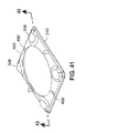
図33は、フィッティング200に予備成形シール470を形成するように構成されたシール成形システム400の一実施形態の分解図である。予備成形シール470は、フィッティング200をパネル114に取り付ける前に、フィッティング200に形成又は成形されるものである。図示の実施形態において、シール成形システム400は、フィッティング200のフィッティングフランジ232と補完し合うように構成された底プレート474を含む。底プレート474は、フィッティングフランジの下面に連結又は組み付けされるように構成されている。モールド体402は、当該モールド体402に特有の内側輪郭面を有しており、以下に述べるようにフィッティング外側輪郭面228と補完し合うように構成されている。
FIG. 33 is an exploded view of one embodiment of a
図33に示すように、一実施形態において、モールド体402又はモールド体部分440は、予備成形シール470の外縁部310に注入口488及び/又は排出口490を形成するための1つ又は複数の穴形成用柱部472を含む。以下に述べるように、注入口488を設けることによって、接着剤又はシーラント316を、予備成形シール470の外縁部310に沿って注入することができ、これによって、フィッティング200及び当該フィッティング200が取り付けられるパネル114に対して外縁部310を容易に接合及びシールすることができる。さらなる実施形態において、底プレート474は、当該底プレート474をフィッティングフランジ232に連結した際に当該フィッティングフランジの外周の周りに延びるように構成された隆起部476を含む。隆起部476は、予備成形シール470の外縁部310に沿ってシール溝312が形成されるように構成されており、これによって、フィッティング200をパネル114に取り付けた後に、パネル114に対して外縁部310の外面を容易に接合及びシールすることができる。
As shown in FIG. 33, in one embodiment, the
図34に示すように、モールド体402を、フィッティング本体部226の周りに組み付け且つ底プレート474に連結することによって、フィッティングフランジ232を包囲し、モールドキャビティ416を規定することができる。フランジ留め具234を、底プレート474に貫通させたり、及び/又はフィッティングフランジ232と螺合により係合させることによって、フィッティングフランジ232に関連付けられたねじ切り穴、ナットプレート、又はその他のねじ受容部をシーラント316が埋めるのを防止することができる。モールド体402は、図14〜図16に示したように一体型のモールドとして形成してもよいし、あるいは、モールド体402は、図6〜図13に示したように、一対のモールド半体444を組み合わせて構成してもよい。シーラント316を、モールド体402に形成された注入口420に注入することによって、パネル114に取り付けられたフィッティング200にシール300を形成するための上述した態様と同様に、予備成形シール470を形成することができる。
As shown in FIG. 34, the
図35〜図36には、底プレート474を除去した後、及びモールド体部分440の一方を除去した後の、予備成形シール470の底面側及び上面側を示している。予備成形シール470は、フィッティングフランジ232に成形され、フィッティング本体部226の周りをシールしている。フィッティングフランジ232内の機械式留め具は、成形プロセス後に取り除かれる。以下に述べるように、1つ又は複数の注入口488及び排出口490が、予備成形シール470の外縁部310に沿って形成されている。
35-36 show the bottom side and top side of the preformed
図37は、予備成形シール470の一部の拡大図であり、予備成形シール470の外縁部310に形成された注入口488を示している。注入口488は、図33に示したようにモールド体402に設けられた穴形成用柱部472によって、形成されたものである。排出口490も、予備成形シール470の外縁部310における反対側に形成されている。さらに、底プレート474に設けられた隆起部476によって、予備成形シール470の外縁部310に沿って形成されたシール溝312も示されている。注入口488、排出口490及びシール溝312によって、フィッティング200をパネル114に取り付けた後に、外縁部310をパネル114に対して容易にシール又は接合することができる。
FIG. 37 is an enlarged view of a portion of the preformed
図38は、シール成形システム400のさらなる実施形態の分解図であり、当該システムは、シール膜480を別途成形し、その後当該シール膜をフィッティング200及びパネル114に接合できるように構成されたものである。シール膜480を形成するためのシール成形システム400は、上述のモールド体402のうちの任意の1つをシール膜用下側プレート482と組み合わせて使用することができる。シール膜用下側プレート482は、フィッティング外側輪郭面228及びパネル表面116に実質的に類似するように構成された下側プレート外側輪郭面484を有する。シール膜用下側プレート482は、突出部486を含み、当該突出部は、フィッティングフランジ232をパネル114に取り付けるための、フィッティングフランジ232から上方に伸張するフランジ留め具234を模したものである。モールド体402は、予備成形シール470について上述したのと同様に、少なくとも1つの穴形成用柱部472を含み、これは、フィッティング200及びパネル114に対するシール膜480の接合を容易にするために、シール膜480に注入口488及び/又は排出口490を形成するためのものである。
FIG. 38 is an exploded view of a further embodiment of a
図39は、シール膜用下側プレート482に連結することによってモールドキャビティ416を規定しているモールド体402を示しており、当該モールドキャビティ416に注入したシーラント316によってシール膜480が形成される。図6〜17に示したモールド体402に関して上述したように、シーラント316は、モールド体402に形成された注入口420に注入される。モールド体402は、排出口422を含んでおり、これによって、空気314を逃がすとともに、モールドキャビティ416が実質的に満たされた後のシーラント316を排出することが可能となっている。図40は、シール膜用下側プレート482からモールド体402を取り外すことによって、硬化後のシール膜480が現れる状態を示している。
FIG. 39 shows a
図41〜図42は、シール膜用下側プレート482から取り外された後のシール膜480を示しており、当該シール膜は、パネル114に取り付けられた状態のフィッティング200に後に接合されるものである。シール膜480は、シール膜用下側プレート482の突出部486及びモールド体402の凹部418の位置に、膨出部308を有する。これに関して、下側プレート外側輪郭面484及びモールド体402は、図43に示すように、シール膜480のどの位置においても、所望の肉厚306でシール膜480を形成する手段を実現している。
41 to 42 show the
図43〜図44は、パネル114に取り付けられたフィッティング200のフロント部206に対するシール膜480の取り付けを示している。シール膜480は、シール膜480の膨出部308がフランジ留め具234と揃うように配置される。シール膜480をフィッティング200に対して配置した後、シーラント316又は接着剤をシール膜480の注入口488に注入することによって、シール膜480をパネル114及びフランジ留め具234に接合する。これに代えて、硬化されたシール膜480を取り付ける前に、最初にフィッティングフランジ232及びフランジ留め具234に手作業でシーラント316を塗布することによって、フィッティング200をパネル114に固定してもよい。次に、硬化されたシール膜480が、シーラント316に取り付けられ、これは、シール膜480の外縁部310がパネル表面116に対してシールされるように、手作業によって当該シール膜480を適所に押し付けることによって行われる。このようにして、シール膜480によって、硬化された、滑らかな上面がもたらされる。シール膜480の下側から押し出されたシーラント316があれば、これを取り除くことによって、取り付けが完了する。図示していないが、シール膜は、複数のシール膜部分(図示せず)として形成してもよく、これらを組み合わせ、図38〜図43に示した一体のシール膜480に関して上述したものと類似のシステムを用いて、パネル114に取り付けられたフィッティングボディ及び/又はフィッティングフランジに接合してもよい。
43 to 44 show attachment of the sealing
図46を参照し、且つ付加的に図4〜図25を参照すると、図46は、パネル114に取り付けられたフィッティング200に対してシール300を成形する方法600の一実施形態を示している。方法600の工程602は、モールド内側輪郭面404及び/又はモールドボア412を有するモールド体を用意することを含む。上記で示唆したように、モールド体402は、一対のモールド半体444として用意してもよく、これらは、それぞれがボア部442を含み、フィッティング200の周りに組み付ける構成とすることができる。例えば、モールド半体444は、図7に示すように、互いの鏡像体として構成することができる。一実施形態において、当該方法は、モールド半体444の末端に形成された噛み合い部446を用いて、モールド半体444同士を連結することを含む。モールド内側輪郭面404は、パネル114に取り付けられたフィッティング200のフィッティング外側輪郭面228と補完し合うように形成される。
With reference to FIG. 46 and additionally with reference to FIGS. 4-25, FIG. 46 illustrates one embodiment of a
図46の方法600における工程604は、モールド体402をフィッティング200に取り付けることを含む。モールド体402は、パネル114及びフィッティング200に連結されるが、これは、1つ又は複数のタイラップ562、クランプ機構566、又は、モールド体402をパネル114に対してクランプするための他の機構によって、各モールド基部406がパネル表面116及びフィッティング本体226に対してシール係合するように行われる。モールド基部406を、パネル表面116と補完し合うように形成することによって、パネル114に対するモールド体402のシール係合性が向上する。この点に関連して、モールド基部406がパネル表面116に対してシール係合するようにモールド体402をフィッティング200に取り付ける工程は、少なくとも1つの磁石542をモールド体402に取り付けることと、パネル114、及び/又は、パネル114の反対側において、追加のモールド体402に連結された追加の磁石542に対して、磁石542を磁気的に連結することを含んでもよい。この磁気的連結によって、磁石542は、モールド体402をパネル表面116上に保持する。
Step 604 in the
図46の方法600における工程606は、モールド体402に形成された注入口420にシーラント316を注入することを含む。上記で示唆したように、シーラント316が実質的にモールドキャビティ416を満たし、モールドキャビティ416が実質的にシーラント316で満たされたことのしるしとして、排出口490からシーラント316流出し始めるまで、シーラント316は連続的にモールドキャビティ416に注入される。シーラント316がモールドキャビティ416に注入されている間、排出口422から空気を逃すことができ、これによって硬化されたシール300内に空隙又は気泡が生じるのを最小限に抑制又は防止することができる。
Step 606 in the
図46の方法600における工程608は、モールドキャビティ416内でシーラント316を硬化させることを含む。上記で示唆したように、シーラント316は、1成分シーラント、2成分シーラント、又は他のシーラント組成を含む。一実施形態において、シーラントは、シリコーンシーラントなどのRTVシーラントを含む。ただし、流体が通るのを防ぐバリアーとして機能するか、又は、フィッティングフランジ232とパネル14との間、もしくは、フランジ留め具234内への水分の進入を防止するシール300を形成するものであれば、いかなるシーラント316をモールドキャビティ416に注入してもよい。
Step 608 in the
図46の方法600における工程610は、シール300が硬化した後に、フィッティング200及び/又はパネル114からモールド体402を取り外すことを含む。一実施形態において、モールド体402は、シール300からモールド内側輪郭面404を容易に外すことができる材料によって形成される。モールド体402にモールド離型剤を予め塗布しておくことによって、モールド体402を容易に取り外せるようにしてもよい。モールド体402の取り外しは、モールド内側輪郭面404に抜き勾配424を設けることによって、さらに容易にすることができる。
Step 610 in the
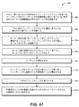
図47を参照し、加えて図33〜図37を参照すると、図47は、パネル114に取り付けるように構成されたフィッティング200の周りに予備成形シール470を成形する方法700の一実施形態を示している。当該方法は、上述のようにモールド体402を用意する工程702を含み、当該モールド体は、パネル114に取り付けるように構成されたフィッティングフランジ232を有するフィッティング200のフィッティング外側輪郭面208と補完し合うように形成されたモールド内側輪郭面404及びモールドボア412を含むものである。当該方法は、モールド体402に少なくとも1つの穴形成用柱部472を設けることと、当該穴形成用柱部472を用いて予備成形シール470の外縁部310に注入口488及び/又は排出口490を形成することによって、外縁部310をパネル114に接合及びシールすることを目的として予備成形シール470の外縁部310に沿って接着剤又はシーラント316を注入するための手段を設けること、とを含む。
With reference to FIG. 47 and in addition to FIGS. 33-37, FIG. 47 illustrates one embodiment of a
図47の方法700における工程704は、パネル114及びフィッティングフランジ232と補完し合うように構成された底プレートを用意することを含む。底プレート474の一実施形態が図33に示されている。当該方法は、底プレート474をフィッティングフランジ232に連結した際にフィッティングフランジの周りに延びるように構成された隆起部476を底プレート474に設けることを含む。この点に関して、当該方法は、予備成形シール470の外縁部310に沿ってシール溝312が形成されるように隆起部476を構成することによって、パネル114に対する外縁部310の接合及びシールを容易にすることを含む。
Step 704 in the
図47の方法700における工程706は、モールド体402及び底プレート474をフィッティングフランジ232に連結することを含む。モールド体402及び底プレート474が、フィッティングフランジ232を包囲し、モールドキャビティ416を形成する。フランジ留め具234をフィッティングフランジ232穴に取り付けることによって、留め具穴(図示せず)をシーラント316が塞ぐのを防止してもよい。
Step 706 in the
図47の方法700における工程708は、モールド体402に形成された注入口420に、シーラント316が実質的にモールドキャビティ416を満たし、モールド体402に形成された排出口490からシーラント316が流出するまで、シーラント316を注入することを含む。上述したように、排出口490からのシーラント316の流出は、モールドキャビティ416が実質的に満たされたことを示唆する。排出口490は、空気314を逃す役割も行う。工程710は、シーラント316を硬化させることを含む。
Step 708 in the
図47の方法700における工程712は、フィッティング200からモールド体402及び底プレート474を取り外して、予備成形シール470を露出させることを含む。予備成形シール470は、フィッティング200に永久的に成形される。工程714は、フィッティング200をパネル114に取り付けることを含む。当該方法の工程716は、予備成形シール470の外縁部310に形成された注入口488に、外縁部310をパネル114に接合する手段として、シーラント316を注入することを含む。
Step 712 in the
図48を参照し、加えて図38〜図43を参照すると、図48は、パネル114に取り付けられたフィッティング200をシールするためのシール膜480を形成する方法800の一実施形態を示している。当該方法は、モールド体402を用意することを含む工程802を含み、当該モールド体は、パネル114に取り付けるように構成されたフィッティングフランジ232を有するフィッティング200のフィッティング外側輪郭面208と補完し合うように形成されたモールド内側輪郭面404及びモールドボア412を含むものである。当該方法は、モールド体402に少なくとも1つの穴形成用柱部472を設けることと、当該穴形成用柱部472を用いてシール膜480に注入口488及び/又は排出口490を形成することによって、予備成形シール470について上述したのと同様に、少なくともパネル114に対するシール膜480の接合を容易にすること、とを含む。
Referring to FIG. 48, and in addition to FIGS. 38-43, FIG. 48 illustrates one embodiment of a
図38の方法800における工程804は、フィッティング外側輪郭面228及びパネル表面116を模した又はこれらに実質的に類似する下側プレート外側輪郭面484を有するシール膜用下側プレート482を用意することを含む。当該方法は、シール膜用下側プレート482に少なくとも1つの突出部486を形成することを含み、これによってフィッティング200をパネル114に取り付けるための、フィッティングフランジ232から外側に突出するフランジ留め具234を模する。
Step 804 in the
図38の方法800における工程806は、図39に示すように、モールド体402をシール膜用下側プレート482に連結することによって、モールドキャビティ416を規定することを含む。方法800の工程808は、モールド体402に形成された注入口420に、シーラント316が実質的にモールドキャビティ416を満たし、モールド体402に形成された排出口490からシーラント316が流出するまで、シーラント316を注入することを含む。方法800の工程810は、シーラント316を硬化させることを含む。
Step 806 in the
図38の方法800における工程812は、図41〜図42に示すように、モールド体402及びシール膜用下側プレート482からシール膜480を取り外すことを含む。方法800の工程814は、図44〜図45に示すように、フィッティング200及びパネル114にシール膜480を装着することを含む。方法800の工程816は、シール膜480をフィッティング200及びパネル114に接合するために、シール膜480に形成された注入口488にシーラント316を注入することによって、パネル14に取り付けられたフィッティング200にシール膜480を接合することを含む。
Step 812 in the
本開示の追加的な改変及び改良は、当業者には明らかであろう。従って、本明細書において記載及び図示した部品の特定の組み合わせは、本開示の実施形態のある種の例を表すことを意図したものであり、本開示の精神及び範囲内の代替の実施形態又は装置を制限することを意図するものではない。 Additional modifications and improvements of the present disclosure will be apparent to those skilled in the art. Accordingly, the particular combinations of parts described and illustrated herein are intended to represent certain examples of embodiments of the present disclosure, and alternative embodiments or embodiments within the spirit and scope of the present disclosure. It is not intended to limit the device.
Claims (12)
フィッティングのフィッティング外側輪郭面と補完し合うように形成されたモールド内側輪郭面を有するモールド体を含み、
前記モールド体は、パネル表面と補完し合うように形成されたモールド基部を有し、
前記モールド体は、モールドキャビティにシーラントを注入するための注入口、及び、空気及びシーラントを前記モールドキャビティから排出するための排出口を含んでおり、
前記モールド体は、前記フィッティングの周りに組み付けるように構成された一対のモールド半体を含んでおり、
前記モールド体は、前記モールド半体に形成された噛み合い部を含んでおり、
前記噛み合い部は、前記各モールド半体の周方向両端におけるモールド分割線に沿って形成された噛み合いタブ−ポケット構造を含み、前記モールド分割線は、前記フィッティングの軸心方向に延びる一対の軸線部と、これら軸線部を繋ぐ傾斜線部とを含み、組み付けられた前記モールド半体を前記フィッティングの軸心方向に直交する方向から側面視にて前記モールド分割線をみたとき、前記一対の軸線部と傾斜線部とが一緒になって前記モールド分割線の範囲内にZ字形状を規定している、シール成形システム。 A seal molding system for forming a seal around a fitting attached to a panel,
A mold body having a mold inner contour surface formed to complement the fitting outer contour surface of the fitting;
The mold body has a mold base formed so as to complement the panel surface;
The mold body includes an inlet for injecting a sealant into the mold cavity, and an outlet for discharging air and sealant from the mold cavity.
The mold body includes a pair of mold halves configured to be assembled about the fitting;
The mold body includes an engagement portion formed in the mold half,
The engagement portion includes an engagement tab-pocket structure formed along a mold dividing line at both circumferential ends of the mold halves, and the mold dividing line includes a pair of axial portions extending in the axial direction of the fitting. When the mold parting line is viewed in a side view from a direction perpendicular to the axial direction of the fitting of the assembled mold half, the pair of axis portions is included. A seal molding system in which a Z-shape is defined within the range of the mold parting line together with the inclined line portion .
フィッティングのフィッティング外側輪郭面と補完し合うように形成されたモールド内側輪郭面を有するモールド体を含み、
前記モールド体は、パネル表面と補完し合うように形成されたモールド基部を有し、
前記モールド体は、モールドキャビティにシーラントを注入するための注入口、及び、空気及びシーラントを前記モールドキャビティから排出するための排出口を含んでおり、
さらに、前記モールド体は、フィッティング基部と補完し合うように構成されたベース部内側輪郭面を有する固定ベース部と、前記固定ベース部の上に取り付け可能であり、且つ、前記フィッティング基部に回転可能に係合したフィッティング特異部と補完し合うように構成された上部内側輪郭面を有する、回転調節可能な上部と、を含み、
前記回転調節可能な上部は、前記上部内側輪郭面の向きを変えて前記フィッティング特異部に揃えるべく、前記固定ベース部に対して回転可能である、シール成形システム。 A seal molding system for forming a seal around a fitting attached to a panel,
A mold body having a mold inner contour surface formed to complement the fitting outer contour surface of the fitting;
The mold body has a mold base formed so as to complement the panel surface;
The mold body includes an inlet for injecting a sealant into the mold cavity, and an outlet for discharging air and sealant from the mold cavity.
Further, the mold body can be mounted on the fixed base portion having a base portion inner contour surface configured to complement the fitting base portion, and can be rotated on the fitting base portion. A rotationally adjustable upper portion having an upper inner contour surface configured to complement the fitting singularity engaged with the
The rotating adjustable top, the order by changing the upper inner contour surface orientation aligned to the fitting unique portion is rotatable relative to the stationary base unit, shea Lumpur molding system.
前記磁石は、前記パネルの反対側に配置され且つ追加のモールド体に連結された追加の磁石と磁気的に連結するように構成されている、請求項1〜6のいずれかに記載のシール成形システム。 At least one magnet fixedly coupled to the mold body to bias the mold body against the panel surface;
The seal molding according to any one of claims 1 to 6, wherein the magnet is configured to be magnetically coupled to an additional magnet disposed on an opposite side of the panel and coupled to an additional mold body. system.
フィッティングのフィッティング外側輪郭面と補完し合うように形成されたモールド内側輪郭面を有するモールド体を含み、
前記モールド体は、パネル表面と補完し合うように形成されたモールド基部を有し、
前記モールド体は、モールドキャビティにシーラントを注入するための注入口、及び、空気及びシーラントを前記モールドキャビティから排出するための排出口を含んでおり、
前記シール成形システムは、フィッティングフランジの下面に連結できるよう、フィッティングフランジと補完し合う構成とされた底プレートをさらに含み、
前記モールド体は、前記フィッティングフランジを包囲し且つ予備成形シールを形成するためのシーラントを入れるモールドキャビティを形成するよう、前記底プレートに連結可能である、シール成形システム。 A seal molding system for forming a seal around a fitting attached to a panel,
A mold body having a mold inner contour surface formed to complement the fitting outer contour surface of the fitting;
The mold body has a mold base formed so as to complement the panel surface;
The mold body includes an inlet for injecting a sealant into the mold cavity, and an outlet for discharging air and sealant from the mold cavity.
The seal molding system further includes a bottom plate configured to complement the fitting flange so that it can be coupled to the lower surface of the fitting flange;
The mold body, the surrounding and fitting flange to form a mold cavity to put sealant for forming the preformed seals, can be connected to the bottom plate, sheet Lumpur molding system.
フィッティングのフィッティング外側輪郭面と補完し合うように形成されたモールド内側輪郭面を有するモールド体を含み、
前記モールド体は、パネル表面と補完し合うように形成されたモールド基部を有し、
前記モールド体は、モールドキャビティにシーラントを注入するための注入口、及び、空気及びシーラントを前記モールドキャビティから排出するための排出口を含んでおり、
前記シール成形システムは、前記フィッティング外側輪郭面及び前記パネル表面を模した下側プレート外側輪郭面を有するシール膜用下側プレートをさらに含み、
前記モールド体は、内部に注入されたシーラントによってシール膜を形成するためのモールドキャビティを規定するよう、前記シール膜用下側プレートと連結可能であり、
前記シール膜を取り外してパネルに取り付けられたフィッティングに接合できるよう、前記シール膜用下側プレートと前記モールド体は互いに分離可能である、シール成形システム。 A seal molding system for forming a seal around a fitting attached to a panel,
A mold body having a mold inner contour surface formed to complement the fitting outer contour surface of the fitting;
The mold body has a mold base formed so as to complement the panel surface;
The mold body includes an inlet for injecting a sealant into the mold cavity, and an outlet for discharging air and sealant from the mold cavity.
The seal molding system further includes a lower plate for a sealing film having a lower plate outer contour surface imitating the fitting outer contour surface and the panel surface,
The mold body is connectable with the lower plate for a seal film so as to define a mold cavity for forming a seal film with a sealant injected therein,
The sealing membrane to be bonded to a fitting attached to the panel by removing the said mold body and the lower plate for the sealing film can be separated from each other, shea Lumpur molding system.
Applications Claiming Priority (3)
| Application Number | Priority Date | Filing Date | Title |
|---|---|---|---|
| US13/845,014 | 2013-03-17 | ||
| US13/845,014 US9259865B2 (en) | 2013-03-17 | 2013-03-17 | Seal molding system and method |
| PCT/US2014/016638 WO2014149283A1 (en) | 2013-03-17 | 2014-02-15 | Seal molding system and method |
Publications (3)
| Publication Number | Publication Date |
|---|---|
| JP2016512178A JP2016512178A (en) | 2016-04-25 |
| JP2016512178A5 JP2016512178A5 (en) | 2016-10-20 |
| JP6276838B2 true JP6276838B2 (en) | 2018-02-07 |
Family
ID=50238461
Family Applications (1)
| Application Number | Title | Priority Date | Filing Date |
|---|---|---|---|
| JP2016500274A Active JP6276838B2 (en) | 2013-03-17 | 2014-02-15 | Seal molding system and method |
Country Status (5)
| Country | Link |
|---|---|
| US (2) | US9259865B2 (en) |
| EP (3) | EP2976201B1 (en) |
| JP (1) | JP6276838B2 (en) |
| CN (1) | CN105189078B (en) |
| WO (1) | WO2014149283A1 (en) |
Families Citing this family (10)
| Publication number | Priority date | Publication date | Assignee | Title |
|---|---|---|---|---|
| US9259865B2 (en) * | 2013-03-17 | 2016-02-16 | The Boeing Company | Seal molding system and method |
| US9895848B2 (en) * | 2015-04-22 | 2018-02-20 | The Boeing Company | Systems and tooling for manufacturing composite parts and related methods |
| JP6436460B2 (en) * | 2015-07-27 | 2018-12-12 | 矢崎総業株式会社 | Mold and molding method |
| US10626992B2 (en) * | 2015-11-30 | 2020-04-21 | The Boeing Company | Sealant containment assembly, system, and method |
| US9897130B2 (en) * | 2016-04-15 | 2018-02-20 | The Boeing Company | Telescoping cap assembly for encapsulating a fastener disposed within a confined space |
| US10087970B2 (en) * | 2016-04-29 | 2018-10-02 | The Boeing Company | Sealant Containment Assembly |
| JP6805405B2 (en) * | 2016-12-21 | 2020-12-23 | 宇部興産機械株式会社 | Split nut switchgear |
| CN110944831A (en) * | 2017-07-27 | 2020-03-31 | 生物辐射实验室股份有限公司 | Progressive press and co-molding system |
| US11045985B2 (en) * | 2018-08-02 | 2021-06-29 | The Boeing Company | Self-holding and self-extracting seal molding system and method |
| US11807175B2 (en) * | 2021-10-08 | 2023-11-07 | Safran Cabin Germany Gmbh | Cable harness grommet and method for using same |
Family Cites Families (32)
| Publication number | Priority date | Publication date | Assignee | Title |
|---|---|---|---|---|
| US1775812A (en) * | 1929-06-10 | 1930-09-16 | Goodrich Co B F | Mold |
| US2892013A (en) * | 1955-05-25 | 1959-06-23 | Douglas Aircraft Co Inc | Bulkhead seal for wire bundles |
| GB958367A (en) | 1960-06-28 | 1964-05-21 | Minnesota Mining & Mfg | Closed moulds for casting gaskets on pipe ends |
| US3692457A (en) * | 1970-01-14 | 1972-09-19 | Pekor Iron Works | Apparatus for centrifugally forming hollow articles |
| US3798586A (en) * | 1972-05-22 | 1974-03-19 | P Huska | Union for connecting electrical conductors |
| US4090294A (en) * | 1976-03-22 | 1978-05-23 | Bicc Limited | Jointing or terminating plastics sheathed electric cable |
| US4134431A (en) | 1977-05-11 | 1979-01-16 | Owens-Corning Fiberglas Corporation | Method of and apparatus for molding spigot rings on pipe sections and product of the method |
| GB2085347B (en) * | 1980-10-14 | 1984-05-02 | Standard Telephones Cables Ltd | Injection mould for coaxial cable jointing |
| US4382049A (en) * | 1981-11-30 | 1983-05-03 | Mcdonnell Douglas Corporation | Forming a lightning spark isolation barrier |
| JPS58128830A (en) * | 1982-01-29 | 1983-08-01 | Sony Corp | Mold apparatus |
| DE3575333D1 (en) * | 1984-10-15 | 1990-02-15 | Ltv Aerospace & Defence | METHOD AND DEVICE FOR APPLYING A SPECIFIC QUANTITY OF SEALANT TO UNprotected FASTENERS. |
| JP2976494B2 (en) * | 1990-07-11 | 1999-11-10 | 市光工業株式会社 | Method of molding protector for vehicle lighting |
| JP2958376B2 (en) * | 1990-07-26 | 1999-10-06 | 金尾 茂樹 | Corrugated pipe with joint and method of integrally forming joint with corrugated pipe |
| US5226837A (en) * | 1990-11-16 | 1993-07-13 | Raychem Corporation | Environmentally protected connection |
| JPH06502960A (en) * | 1990-11-16 | 1994-03-31 | レイケム・コーポレイション | environmental protection connections |
| DE4341064C1 (en) | 1993-12-02 | 1995-07-13 | Bayer Ag | Extension piece for roller given a plastics cladding |
| DE19503346C2 (en) | 1995-02-02 | 1998-04-16 | Puspas Armaturen Gmbh | Pipe component |
| JPH08264060A (en) * | 1995-03-23 | 1996-10-11 | Ngk Insulators Ltd | Connecting method for polymer insulator |
| JPH099447A (en) * | 1995-06-21 | 1997-01-10 | Fujikura Ltd | Connection method of crosslinked polyethylane insulation power cable and connecting metallic mold device |
| DE19728234C2 (en) | 1997-07-02 | 2001-09-27 | Pvb Medizintechnik Gmbh & Co K | Rooster |
| JP4250810B2 (en) * | 1999-06-09 | 2009-04-08 | 株式会社ブリヂストン | Method of forming the outer shell of the seismic isolation device |
| DE19949471C1 (en) | 1999-10-14 | 2001-05-03 | Cr Elastomere Gmbh | Production of valve shaft seal, comprises metallic reinforcement ring against spaced contact zones at the mold section with overflow zone between them to take overflow elastomer |
| DK1432917T3 (en) * | 2001-09-28 | 2006-06-12 | Prc Desoto Int Inc | Pre-mixed and frozen sealing caps |
| US6729477B2 (en) * | 2002-05-03 | 2004-05-04 | Arvin Technologies, Inc. | Fluid filter retainer and seal apparatus |
| US20050211101A1 (en) | 2004-03-23 | 2005-09-29 | Finnie Richard B Ii | Single serving silicone receptacle |
| CA2706964A1 (en) | 2007-11-29 | 2009-06-04 | Bluescope Steel Limited | Moulding process and apparatus |
| WO2009129657A1 (en) * | 2008-04-23 | 2009-10-29 | Marco Skates Limited | Foot casting system |
| US20100330224A1 (en) * | 2009-06-25 | 2010-12-30 | Red Wood Enterprise Co., Ltd | Shaping mold of bushing base |
| US8616868B2 (en) * | 2011-02-28 | 2013-12-31 | Physical Systems, Inc. | Sealant mold fixture for a domed cap |
| WO2012150897A1 (en) | 2011-05-03 | 2012-11-08 | Shl Group Ab | Mold assembly and method for manufacturing a syringe container |
| JP5783089B2 (en) * | 2012-03-01 | 2015-09-24 | Jfeエンジニアリング株式会社 | Method and apparatus for anticorrosion coating of steel weld joint |
| US9259865B2 (en) * | 2013-03-17 | 2016-02-16 | The Boeing Company | Seal molding system and method |
-
2013
- 2013-03-17 US US13/845,014 patent/US9259865B2/en active Active
-
2014
- 2014-02-15 JP JP2016500274A patent/JP6276838B2/en active Active
- 2014-02-15 CN CN201480016386.3A patent/CN105189078B/en active Active
- 2014-02-15 EP EP14708723.3A patent/EP2976201B1/en active Active
- 2014-02-15 EP EP18167936.6A patent/EP3369546B1/en active Active
- 2014-02-15 EP EP18167932.5A patent/EP3369545B1/en active Active
- 2014-02-15 WO PCT/US2014/016638 patent/WO2014149283A1/en active Application Filing
-
2016
- 2016-01-20 US US15/001,908 patent/US9993952B2/en active Active
Also Published As
| Publication number | Publication date |
|---|---|
| US9259865B2 (en) | 2016-02-16 |
| EP2976201A1 (en) | 2016-01-27 |
| EP3369545B1 (en) | 2020-04-22 |
| WO2014149283A1 (en) | 2014-09-25 |
| CN105189078B (en) | 2017-06-06 |
| JP2016512178A (en) | 2016-04-25 |
| EP3369546B1 (en) | 2020-04-08 |
| US9993952B2 (en) | 2018-06-12 |
| US20140261994A1 (en) | 2014-09-18 |
| US20160136857A1 (en) | 2016-05-19 |
| EP3369545A1 (en) | 2018-09-05 |
| EP2976201B1 (en) | 2018-05-09 |
| CN105189078A (en) | 2015-12-23 |
| EP3369546A1 (en) | 2018-09-05 |
Similar Documents
| Publication | Publication Date | Title |
|---|---|---|
| JP6276838B2 (en) | Seal molding system and method | |
| CN105599217B (en) | Use the injection molding fastener cap sealing element in thermoplastic elastic material scene | |
| US20160159493A1 (en) | Cap to accommodate washers | |
| EP0538009B1 (en) | Method and apparatus for protection of cable splices | |
| EP1626219A2 (en) | Seal devices and sealing methods | |
| KR101648311B1 (en) | Line post Insulator | |
| KR101868075B1 (en) | Filler assembly for cable gland | |
| KR950031433A (en) | Method and apparatus for manufacturing tire mold | |
| EP2343181A1 (en) | Connection port for composite moulding | |
| JP2016512178A5 (en) | ||
| US10766211B2 (en) | Method of forming pressure pad or other flexible element for use during cure of composite materials | |
| US8708374B1 (en) | Concrete sealing ring for set screw electrical fittings or connectors | |
| EP3006371B1 (en) | Dispenser apparatus for curable liquid material | |
| EP0382536B1 (en) | Apparatus for moulding a fluid settable material | |
| KR100744173B1 (en) | Manhole forming apparatus with fixed unit for pipe connecter | |
| CN110553034B (en) | Combined dynamic seal ring | |
| HUE030571T2 (en) | Mounting box for mounting in a wall | |
| JPH045028A (en) | Laying method of insert in synthetic resin molding | |
| WO1991010546A1 (en) | A mould for moulding of a thermosetting substance | |
| JP2004216334A (en) | Piping joint of septic tank | |
| US11045985B2 (en) | Self-holding and self-extracting seal molding system and method | |
| US11602875B2 (en) | Injection molding apparatus and injection molding method | |
| CN106809372A (en) | Sealant accommodates component, system and method | |
| JPH045011A (en) | Molding method for synthetic resin molded body with integrated cushion body | |
| KR100791993B1 (en) | Connecting pipe fixer for manhole forming |
Legal Events
| Date | Code | Title | Description |
|---|---|---|---|
| A521 | Request for written amendment filed |
Free format text: JAPANESE INTERMEDIATE CODE: A523 Effective date: 20160902 |
|
| A621 | Written request for application examination |
Free format text: JAPANESE INTERMEDIATE CODE: A621 Effective date: 20160902 |
|
| A977 | Report on retrieval |
Free format text: JAPANESE INTERMEDIATE CODE: A971007 Effective date: 20170810 |
|
| A131 | Notification of reasons for refusal |
Free format text: JAPANESE INTERMEDIATE CODE: A131 Effective date: 20170822 |
|
| A131 | Notification of reasons for refusal |
Free format text: JAPANESE INTERMEDIATE CODE: A131 Effective date: 20170926 |
|
| A521 | Request for written amendment filed |
Free format text: JAPANESE INTERMEDIATE CODE: A523 Effective date: 20171218 |
|
| TRDD | Decision of grant or rejection written | ||
| A01 | Written decision to grant a patent or to grant a registration (utility model) |
Free format text: JAPANESE INTERMEDIATE CODE: A01 Effective date: 20180109 |
|
| A61 | First payment of annual fees (during grant procedure) |
Free format text: JAPANESE INTERMEDIATE CODE: A61 Effective date: 20180112 |
|
| R150 | Certificate of patent or registration of utility model |
Ref document number: 6276838 Country of ref document: JP Free format text: JAPANESE INTERMEDIATE CODE: R150 |
|
| R250 | Receipt of annual fees |
Free format text: JAPANESE INTERMEDIATE CODE: R250 |
|
| R250 | Receipt of annual fees |
Free format text: JAPANESE INTERMEDIATE CODE: R250 |
|
| R250 | Receipt of annual fees |
Free format text: JAPANESE INTERMEDIATE CODE: R250 |
|
| R250 | Receipt of annual fees |
Free format text: JAPANESE INTERMEDIATE CODE: R250 |