JP6271228B2 - Crimping method of electric wire to terminal - Google Patents
Crimping method of electric wire to terminal Download PDFInfo
- Publication number
- JP6271228B2 JP6271228B2 JP2013242919A JP2013242919A JP6271228B2 JP 6271228 B2 JP6271228 B2 JP 6271228B2 JP 2013242919 A JP2013242919 A JP 2013242919A JP 2013242919 A JP2013242919 A JP 2013242919A JP 6271228 B2 JP6271228 B2 JP 6271228B2
- Authority
- JP
- Japan
- Prior art keywords
- electric wire
- crimping
- terminal
- barrel
- wire
- Prior art date
- Legal status (The legal status is an assumption and is not a legal conclusion. Google has not performed a legal analysis and makes no representation as to the accuracy of the status listed.)
- Active
Links
- 238000002788 crimping Methods 0.000 title claims description 66
- 238000000034 method Methods 0.000 title claims description 18
- 239000011248 coating agent Substances 0.000 claims description 23
- 238000000576 coating method Methods 0.000 claims description 23
- 238000012545 processing Methods 0.000 claims description 5
- 238000004519 manufacturing process Methods 0.000 claims description 3
- 239000002184 metal Substances 0.000 description 7
- 230000006835 compression Effects 0.000 description 5
- 238000007906 compression Methods 0.000 description 5
- 230000009191 jumping Effects 0.000 description 4
- 238000003825 pressing Methods 0.000 description 3
- 238000007796 conventional method Methods 0.000 description 2
- 238000005452 bending Methods 0.000 description 1
- 230000003139 buffering effect Effects 0.000 description 1
- 238000012790 confirmation Methods 0.000 description 1
- 238000005520 cutting process Methods 0.000 description 1
- 230000007423 decrease Effects 0.000 description 1
- 238000010586 diagram Methods 0.000 description 1
- 238000009413 insulation Methods 0.000 description 1
- 235000013372 meat Nutrition 0.000 description 1
- 238000012986 modification Methods 0.000 description 1
- 230000004048 modification Effects 0.000 description 1
- 238000004080 punching Methods 0.000 description 1
- 239000000758 substrate Substances 0.000 description 1
Images


Classifications
-
- H—ELECTRICITY
- H01—ELECTRIC ELEMENTS
- H01R—ELECTRICALLY-CONDUCTIVE CONNECTIONS; STRUCTURAL ASSOCIATIONS OF A PLURALITY OF MUTUALLY-INSULATED ELECTRICAL CONNECTING ELEMENTS; COUPLING DEVICES; CURRENT COLLECTORS
- H01R4/00—Electrically-conductive connections between two or more conductive members in direct contact, i.e. touching one another; Means for effecting or maintaining such contact; Electrically-conductive connections having two or more spaced connecting locations for conductors and using contact members penetrating insulation
- H01R4/10—Electrically-conductive connections between two or more conductive members in direct contact, i.e. touching one another; Means for effecting or maintaining such contact; Electrically-conductive connections having two or more spaced connecting locations for conductors and using contact members penetrating insulation effected solely by twisting, wrapping, bending, crimping, or other permanent deformation
- H01R4/18—Electrically-conductive connections between two or more conductive members in direct contact, i.e. touching one another; Means for effecting or maintaining such contact; Electrically-conductive connections having two or more spaced connecting locations for conductors and using contact members penetrating insulation effected solely by twisting, wrapping, bending, crimping, or other permanent deformation by crimping
- H01R4/183—Electrically-conductive connections between two or more conductive members in direct contact, i.e. touching one another; Means for effecting or maintaining such contact; Electrically-conductive connections having two or more spaced connecting locations for conductors and using contact members penetrating insulation effected solely by twisting, wrapping, bending, crimping, or other permanent deformation by crimping for cylindrical elongated bodies, e.g. cables having circular cross-section
- H01R4/184—Electrically-conductive connections between two or more conductive members in direct contact, i.e. touching one another; Means for effecting or maintaining such contact; Electrically-conductive connections having two or more spaced connecting locations for conductors and using contact members penetrating insulation effected solely by twisting, wrapping, bending, crimping, or other permanent deformation by crimping for cylindrical elongated bodies, e.g. cables having circular cross-section comprising a U-shaped wire-receiving portion
- H01R4/185—Electrically-conductive connections between two or more conductive members in direct contact, i.e. touching one another; Means for effecting or maintaining such contact; Electrically-conductive connections having two or more spaced connecting locations for conductors and using contact members penetrating insulation effected solely by twisting, wrapping, bending, crimping, or other permanent deformation by crimping for cylindrical elongated bodies, e.g. cables having circular cross-section comprising a U-shaped wire-receiving portion combined with a U-shaped insulation-receiving portion
-
- H—ELECTRICITY
- H01—ELECTRIC ELEMENTS
- H01R—ELECTRICALLY-CONDUCTIVE CONNECTIONS; STRUCTURAL ASSOCIATIONS OF A PLURALITY OF MUTUALLY-INSULATED ELECTRICAL CONNECTING ELEMENTS; COUPLING DEVICES; CURRENT COLLECTORS
- H01R43/00—Apparatus or processes specially adapted for manufacturing, assembling, maintaining, or repairing of line connectors or current collectors or for joining electric conductors
- H01R43/04—Apparatus or processes specially adapted for manufacturing, assembling, maintaining, or repairing of line connectors or current collectors or for joining electric conductors for forming connections by deformation, e.g. crimping tool
- H01R43/048—Crimping apparatus or processes
- H01R43/05—Crimping apparatus or processes with wire-insulation stripping
-
- H—ELECTRICITY
- H01—ELECTRIC ELEMENTS
- H01R—ELECTRICALLY-CONDUCTIVE CONNECTIONS; STRUCTURAL ASSOCIATIONS OF A PLURALITY OF MUTUALLY-INSULATED ELECTRICAL CONNECTING ELEMENTS; COUPLING DEVICES; CURRENT COLLECTORS
- H01R43/00—Apparatus or processes specially adapted for manufacturing, assembling, maintaining, or repairing of line connectors or current collectors or for joining electric conductors
- H01R43/28—Apparatus or processes specially adapted for manufacturing, assembling, maintaining, or repairing of line connectors or current collectors or for joining electric conductors for wire processing before connecting to contact members, not provided for in groups H01R43/02 - H01R43/26
Landscapes
- Engineering & Computer Science (AREA)
- Manufacturing & Machinery (AREA)
- Connections Effected By Soldering, Adhesion, Or Permanent Deformation (AREA)
- Manufacturing Of Electrical Connectors (AREA)
- Processing Of Terminals (AREA)
Description
本発明は、端子への電線の圧着方法に関する。 The present invention relates to a method for crimping an electric wire to a terminal.
従来、端子への電線の圧着方法としては、下記の特許文献1に示す方法が開示されている。特許文献1では、被覆電線の芯線及び被覆の前端を端子金具で加締めている。インシュレーションバレルの一対の突片は、前後にずれて形成されており、前側にずれた突片の前端からは押さえ片が前方に突出している。押さえ片は、被覆21の前縁の前方までを覆い、被覆の前縁の跳ね上がりを防止している。 Conventionally, as a method for crimping an electric wire to a terminal, a method shown in Patent Document 1 below is disclosed. In Patent Document 1, the core wire of the covered electric wire and the front end of the covering are crimped with terminal fittings. The pair of protrusions of the insulation barrel are formed so as to be displaced forward and backward, and a pressing piece protrudes forward from the front end of the protrusion displaced to the front side. The pressing piece covers up to the front of the front edge of the covering 21 to prevent the front edge of the covering from jumping up.
上記従来の端子への電線の圧着方法では、押さえ片により目視で被覆状体を確認できないため、端子金具に確認窓を設ける必要があった。 In the conventional method for crimping an electric wire to a terminal, it is necessary to provide a confirmation window on the terminal fitting because the covering cannot be visually confirmed by the pressing piece.
本発明は斯かる課題に鑑みてなされたもので、上記課題を解決できる端子への電線の圧着方法を提供することを目的とする。 This invention is made | formed in view of such a subject, and it aims at providing the crimping | compression-bonding method of the electric wire to the terminal which can solve the said subject.
このような目的を達成するために、本発明の端子への電線の圧着方法は、端子への電線の圧着方法であって、被覆の一部が剥ぎ取られて芯線を露出された電線において、残っている被覆の先端を全周に亘って先細りに加工し、前記先細り部分の一方の端部であって、前記芯線が露出された側の端部をバレルから露出するように配置し、前記先細り部分の前記芯線側と反対側の端部である前記先細り部分の境界が、前記端子のバレル内に収まるように、前記電線を前記バレル内に配置し、前記電線を前記端子に圧着することを特徴とする。
また、本発明は、前記被覆の先端を全周に亘って段付き形状に加工することによって前記先細り部分を形成することを特徴とする。
また、本発明は、前記被覆の先端を全周に亘って円錐形状に加工することによって前記先細り部分を形成することを特徴とする。
本発明の端子へ電線を圧着して電線付き端子を製造する方法は、被覆の一部が剥ぎ取られて芯線を露出された電線において、残っている被覆の先端を全周に亘って先細りに加工し、前記先細り部分の一方の端部であって、前記芯線が露出された側の端部をバレルから露出するように配置し、前記先細り部分の前記芯線側と反対側の端部である前記先細り部分の境界が、前記端子のバレル内に収まるように、前記電線を前記バレル内に配置し、前記電線を前記端子に圧着することを特徴とする。
In order to achieve such an object, the crimping method of the electric wire to the terminal of the present invention is a crimping method of the electric wire to the terminal, in which the core wire is exposed by stripping a part of the coating, The tip of the remaining coating is tapered over the entire circumference , arranged at one end of the tapered portion so that the end on the side where the core wire is exposed is exposed from the barrel, The wire is placed in the barrel so that the boundary of the tapered portion, which is the end of the tapered portion opposite to the core wire side, is within the barrel of the terminal, and the wire is crimped to the terminal. It is characterized by .
Further, the present invention is characterized in that the tapered portion is formed by processing the tip of the coating into a stepped shape over the entire circumference.
Further, the present invention is characterized in that the tapered portion is formed by processing the tip of the coating into a conical shape over the entire circumference.
In the method of manufacturing a terminal with an electric wire by crimping an electric wire to the terminal of the present invention, in the electric wire in which a part of the coating is peeled off and the core wire is exposed, the tip of the remaining coating is tapered over the entire circumference. The one end portion of the tapered portion that is processed and disposed so that the end portion on the side where the core wire is exposed is exposed from the barrel, and is the end portion on the side opposite to the core wire side of the tapered portion. The electric wire is disposed in the barrel so that a boundary of the tapered portion is within the barrel of the terminal, and the electric wire is crimped to the terminal.
本発明によれば、被覆の先端を全周に亘って先細りに加工するという簡単な構成で、バレルからの被覆の飛び出しを防止できる。 According to the present invention, it is possible to prevent the coating from jumping out of the barrel with a simple configuration in which the tip of the coating is tapered over the entire circumference.
以下、図面を参照して、本発明の一実施形態を説明する。
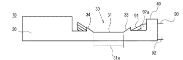
なお、図1は、本実施形態の端子への電線の圧着構造を示す図であり、(a)は平面図,(b)は側面図である。
Hereinafter, an embodiment of the present invention will be described with reference to the drawings.
1A and 1B are diagrams showing a crimping structure of an electric wire to a terminal according to the present embodiment, wherein FIG. 1A is a plan view and FIG. 1B is a side view.
本実施形態の端子への電線の圧着構造は、図1に示すように、圧着端子金具10で電線90を加締めて構成されている。
As shown in FIG. 1, the crimping structure of the electric wire to the terminal of the present embodiment is configured by crimping the
圧着端子金具10は、導電性の基板を打ち抜き折り曲げ加工して形成されており、電気接触部20と、芯線バレル30と、電線バレル40とで構成されている。
The
電気接触部20は、長手方向の一側(図示左側)が開口となった箱状の雌型である。電気接触部20には、雄型の圧着端子金具の電気接触部が挿入される。
The
電線バレル40は、電線90の被覆92が収容された状態で、端子圧着機により加締められ、被覆92と圧着している。
The
また、芯線バレル30は、電気接触部20と電線バレル40の間に形成されている。芯線バレル30は、電線90の被覆92が剥ぎ取られた芯線91が収容された状態で、端子圧着機により加締められ、芯線91と圧着している。
The
芯線バレル30の圧着片31の中央部分は、上面が略水平に形成された完全圧縮部31aとなっている。完全圧縮部31aでは、芯線91が圧着片31に加締められて完全な圧縮状態となっている。完全圧縮部31aの両側には、余肉部である後ベルマウス部33及び前ベルマウス部34が形成されている。
The central part of the crimping
後ベルマウス部33及び前ベルマウス部34は、芯線バレル30の圧着片31が端子圧着機で完全に加締められていない部分であり、圧着片31で芯線91が完全に圧縮されていない状態となっている。このため、後ベルマウス部33及び前ベルマウス部34では、芯線バレル30の圧着片31の後側部分及び前側部分の上面が完全圧縮部31aから上方に延びている。前ベルマウス部34からは、芯線91の先端部分が上方に向けて斜めに延びている。
The rear
電千バレル40の圧着片41は、端子圧着機で全体が完全に加締められており、圧着片41で被覆92が芯線91と共に完全に圧縮された状態となっている。このため、電線バレル40では、圧着片41で締め付けられた被覆92が変形し、圧着片41から突出した部分に余肉部が形成されている。被覆92の先端が全周に亘って円錐形状92aに加工されていることから、電線バレル40先端から突出した被覆92の長さは、圧着片41の上下方向の中央部から上面側にかけて徐々に短くなる。
The crimping
次に、圧着端子金具10に電線90を圧着して、端子への電線の圧着構造を形成する方法について説明する。
Next, a method of crimping the
圧着端子金具10に電線90を圧着する際には、まず、図2に示すように、電線90の先端の被覆92を剥ぎ取って芯線91の皮むきをし、被覆92の先端を全周に亘って円錐形状に加工する。この加工は、被覆92の皮むきされた先端の円錐形状92aが、被覆92の軸線方向に対して傾斜するように、被覆92の先端を切断することで行われる。
When crimping the
次に電線90の被覆92が剥ぎ取られた芯線91が芯線バレル30に収容されるよう、電線90を電線バレル40内に配置する。このとき、被覆92の先端の円錐形状92aの端部が芯線バレル30内に収まるようにする。
Next, the
続いて、図3に示すように、芯線バレル30の圧着片31を、端子圧着機の上圧着型81と下圧着型82との間に配置し、上圧着型81と下圧着型82とで芯線バレル30を加締める。上圧着型81は、圧着面85の前後の端部にテーパ部83,84が設けられている。一方、下圧着型82は、圧着面86が面一に形成されている。
Subsequently, as shown in FIG. 3, the crimping
このため、上圧着型81と下圧着型82とで芯線バレル30が加締められると、図4に示すように、圧着片31には上述の後ベルマウス部33及び前ベルマウス部34が形成される。また、図4に示すように、芯線91の先端が屈曲して前ベルマウス部34から斜め上方に延びる。
For this reason, when the
続いて、図5に示すように、電線バレル40の圧着片41を、端子圧着機の上圧着型87と下圧着型88との間に配置し、上圧着型87と下圧着型88とで電線バレル40を加締める。上圧着型87と下圧着型88とで電線バレル40が加締められると、図6に示すように、圧着片41で締め付けられた被覆92が変形し、圧着片41から突出した部分かに余肉部が形成される。
Subsequently, as shown in FIG. 5, the crimping
全ての芯線91の先端が揃えて加工されている場合には、図7に示すように、前ベルマウス部34先端から突出した芯線91が、前ベルマウス部34の高さを超えて延びてしまう。
When the tips of all the
しかしながら、本実施形態では、被覆92の先端が全周に亘って円錐形状に加工されていることから、電線90がどの方向を向いていても、図6に示すように、電線バレル40先端から突出した被覆92の長さは、圧着片41の上下方向の中央部から上面側にかけて徐々に短くなる。
However, in this embodiment, since the tip of the covering 92 is processed into a conical shape over the entire circumference, no matter which direction the
本実施形態によれば、電線90の皮むきされた被覆92の先端が全周に亘って円錐形状に加工されているので、電線90がどの方向を向いていても芯線バレル30からの被覆92の飛び出しを防止できる。このため、圧着端子金具10への電線90の圧着作業を容易にすることができる。この結果、電線90の皮むきされた被覆92の先端を全周に亘って先細りに加工するという簡単な構成で、電線バレル40からの被覆92の飛び出しを防止できる。
According to the present embodiment, since the tip of the covering 92 peeled off of the
また、本実施形態によれば、端子キャビティと被覆92との緩衝を抑えられ、端子キャビティ内に圧着端子金具10をスムーズに挿入できる。また、クリンプハイトを最適値とすることもできる。 Further, according to this embodiment, the buffering between the terminal cavity and the covering 92 can be suppressed, and the crimp terminal fitting 10 can be smoothly inserted into the terminal cavity. Also, the crimp height can be set to an optimum value.
なお、上記実施形態では、被覆92の先端の円錐形状92aが、被覆92の軸線方向に対して傾斜している場合について説明した。しかしながら、電線90の皮むきされた芯線91の先端が全周に亘って円錐形状に加工されているのであれば、円錐形状92aの傾斜角度は任意である。
In the above embodiment, the case where the
また、上記実施形態では、被覆92の先端の円錐形状92aの端部が圧着端子金具10の電線バレル40内に収まるよう、電線90を電線バレル40内に配置した場合について説明した。しかしながら、電線90は、必ずしも芯線91の先端の円錐形状92aの端部が圧着端子金具10の電線バレル40内に収まるよう配置する必要はなく、芯線91の先端の円錐形状92aの端部が電線バレル40の外側に位置していてもよい。
In the above embodiment, the case where the
また、上記実施形態では、電線90の皮むきされた被覆92の先端を全周に亘って円錐形状に加工した場合について説明したが、電線90の皮むきされた被覆92の先端が全周に亘って先細りに加工されているのであれば、その形状は任意である。例えば、図8に示すように、電線90の皮むきされた被覆92の先端を全周に亘って段付き形状に加工してもよい。
Moreover, although the said embodiment demonstrated the case where the front-end | tip of the coating | coated 92 with which the
この構成によっても、電線90がどの方向を向いていても、電線バレル40先端から突出した芯線91の長さが、圧着片31の上下方向の中央部よりも上面側が短くなるので、電線90がどの方向を向いていても電線バレル40からの被覆92の飛び出しを防止できる。このため、圧着端子金具10への電線90の圧着作業を容易にすることができる。
Even in this configuration, the length of the
10 圧着端子金具
20 電気接触部
30 芯線バレル
31 圧着片
31a 完全圧縮部
33 後ベルマウス部
34 前ベルマウス部
40 電線バレル
41 圧着片
81 上圧着型
82 下圧着型
83,84 テーパ部
85 圧着面
86 圧着面
87 上圧着型
88 下圧着型
90 電線
91 芯線
92 被覆
92a 円錐形状
DESCRIPTION OF
Claims (4)
被覆の一部が剥ぎ取られて芯線を露出された電線において、残っている被覆の先端を全周に亘って先細りに加工し、
前記先細り部分の一方の端部であって、前記芯線が露出された側の端部をバレルから露出するように配置し、
前記先細り部分の前記芯線側と反対側の端部である前記先細り部分の境界が、前記端子のバレル内に収まるように、前記電線を前記バレル内に配置し、
前記電線を前記端子に圧着することを特徴とする端子への電線の圧着方法。 A method of crimping an electric wire to a terminal,
In the electric wire in which a part of the coating is peeled off and the core wire is exposed, the tip of the remaining coating is tapered to the entire circumference,
It is one end of the tapered portion, and is arranged so that the end on the side where the core wire is exposed is exposed from the barrel,
The wire is arranged in the barrel so that the boundary of the tapered portion that is the end of the tapered portion opposite to the core wire side is within the barrel of the terminal,
A method for crimping an electric wire to a terminal, wherein the electric wire is crimped to the terminal.
被覆の一部が剥ぎ取られて芯線を露出された電線において、残っている被覆の先端を全周に亘って先細りに加工し、
前記先細り部分の一方の端部であって、前記芯線が露出された側の端部をバレルから露出するように配置し、
前記先細り部分の前記芯線側と反対側の端部である前記先細り部分の境界が、前記端子のバレル内に収まるように、前記電線を前記バレル内に配置し、
前記電線を前記端子に圧着することを特徴とする電線付き端子を製造する方法。 A method of manufacturing a terminal with an electric wire by crimping an electric wire to the terminal,
In the electric wire in which a part of the coating is peeled off and the core wire is exposed, the tip of the remaining coating is tapered to the entire circumference,
It is one end of the tapered portion, and is arranged so that the end on the side where the core wire is exposed is exposed from the barrel,
The wire is arranged in the barrel so that the boundary of the tapered portion that is the end of the tapered portion opposite to the core wire side is within the barrel of the terminal,
A method of manufacturing a terminal with an electric wire, wherein the electric wire is crimped to the terminal.
Priority Applications (5)
| Application Number | Priority Date | Filing Date | Title |
|---|---|---|---|
| JP2013242919A JP6271228B2 (en) | 2013-11-25 | 2013-11-25 | Crimping method of electric wire to terminal |
| DE112014005350.3T DE112014005350T5 (en) | 2013-11-25 | 2014-11-13 | Electric line with a connection and manufacturing process for electrical line with connection |
| CN201480063980.8A CN105765789B (en) | 2013-11-25 | 2014-11-13 | The manufacturing method of electric wire with terminal and the electric wire with terminal |
| PCT/JP2014/080065 WO2015076177A1 (en) | 2013-11-25 | 2014-11-13 | Electric wire with terminals and manufacturing method for electric wire with terminals |
| US15/154,080 US20160254603A1 (en) | 2013-11-25 | 2016-05-13 | Electric wire with terminal and manufacturing method for electric wire with terminal |
Applications Claiming Priority (1)
| Application Number | Priority Date | Filing Date | Title |
|---|---|---|---|
| JP2013242919A JP6271228B2 (en) | 2013-11-25 | 2013-11-25 | Crimping method of electric wire to terminal |
Publications (2)
| Publication Number | Publication Date |
|---|---|
| JP2015103393A JP2015103393A (en) | 2015-06-04 |
| JP6271228B2 true JP6271228B2 (en) | 2018-01-31 |
Family
ID=53179443
Family Applications (1)
| Application Number | Title | Priority Date | Filing Date |
|---|---|---|---|
| JP2013242919A Active JP6271228B2 (en) | 2013-11-25 | 2013-11-25 | Crimping method of electric wire to terminal |
Country Status (5)
| Country | Link |
|---|---|
| US (1) | US20160254603A1 (en) |
| JP (1) | JP6271228B2 (en) |
| CN (1) | CN105765789B (en) |
| DE (1) | DE112014005350T5 (en) |
| WO (1) | WO2015076177A1 (en) |
Families Citing this family (5)
| Publication number | Priority date | Publication date | Assignee | Title |
|---|---|---|---|---|
| JP6674433B2 (en) * | 2017-11-28 | 2020-04-01 | 矢崎総業株式会社 | Manufacturing method of electric wire with terminal and electric wire with terminal |
| JP6709818B2 (en) * | 2018-03-29 | 2020-06-17 | 矢崎総業株式会社 | Wire with terminal |
| JP2019212458A (en) * | 2018-06-04 | 2019-12-12 | 矢崎総業株式会社 | Terminal-equipped wire and manufacturing method thereof |
| JP7111784B2 (en) * | 2020-09-11 | 2022-08-02 | 矢崎総業株式会社 | Female contact manufacturing method |
| DE102021127516A1 (en) * | 2020-11-19 | 2022-05-19 | Yazaki Corporation | Electrical cable with connection and connection crimping device |
Family Cites Families (12)
| Publication number | Priority date | Publication date | Assignee | Title |
|---|---|---|---|---|
| JPS56115889U (en) * | 1980-02-06 | 1981-09-05 | ||
| DE19902034A1 (en) * | 1999-01-20 | 2000-07-27 | Continental Teves Ag & Co Ohg | Hydraulic unit, especially for hydraulic, slip-regulated motor vehicle braking system, has electrical plug connector containing plug in form of coaxial conductor and corresponding socket |
| JP2005124379A (en) * | 2003-10-17 | 2005-05-12 | Tomoya Sekiguchi | Coaxial cable joint configuration and its processing method |
| EP2151891A1 (en) * | 2008-08-06 | 2010-02-10 | Sumitomo Wiring Systems, Ltd. | A terminal fitting and a method of forming it |
| JP2010049896A (en) * | 2008-08-20 | 2010-03-04 | Sumitomo Wiring Syst Ltd | Connector |
| JP5195230B2 (en) * | 2008-09-26 | 2013-05-08 | 住友電装株式会社 | Electric wire with terminal bracket |
| JP5375687B2 (en) * | 2010-03-15 | 2013-12-25 | 株式会社オートネットワーク技術研究所 | Terminal fittings and wires with terminal fittings |
| TWI403880B (en) * | 2010-11-30 | 2013-08-01 | Inventec Corp | Server |
| JP2012134096A (en) * | 2010-12-24 | 2012-07-12 | Sumitomo Wiring Syst Ltd | Terminal fitting |
| JP5601233B2 (en) * | 2011-02-07 | 2014-10-08 | 住友電装株式会社 | Terminal fitting |
| JP2013149598A (en) * | 2011-12-21 | 2013-08-01 | Auto Network Gijutsu Kenkyusho:Kk | Terminal and manufacturing method of electric wire having the same |
| JP5914942B2 (en) * | 2012-07-30 | 2016-05-11 | 矢崎総業株式会社 | Aluminum wire with terminal |
-
2013
- 2013-11-25 JP JP2013242919A patent/JP6271228B2/en active Active
-
2014
- 2014-11-13 DE DE112014005350.3T patent/DE112014005350T5/en not_active Withdrawn
- 2014-11-13 CN CN201480063980.8A patent/CN105765789B/en active Active
- 2014-11-13 WO PCT/JP2014/080065 patent/WO2015076177A1/en active Application Filing
-
2016
- 2016-05-13 US US15/154,080 patent/US20160254603A1/en not_active Abandoned
Also Published As
| Publication number | Publication date |
|---|---|
| DE112014005350T5 (en) | 2016-08-18 |
| US20160254603A1 (en) | 2016-09-01 |
| JP2015103393A (en) | 2015-06-04 |
| WO2015076177A1 (en) | 2015-05-28 |
| CN105765789A (en) | 2016-07-13 |
| CN105765789B (en) | 2018-05-29 |
Similar Documents
| Publication | Publication Date | Title |
|---|---|---|
| JP5374208B2 (en) | Crimp terminal fitting | |
| JP5884986B2 (en) | Aluminum wire with crimp terminal | |
| JP6271228B2 (en) | Crimping method of electric wire to terminal | |
| JP6422240B2 (en) | Connection structure, wire harness, and connector | |
| JP5606127B2 (en) | Connection structure of crimp terminal to wire | |
| JP5920284B2 (en) | Electric wire with terminal | |
| JP5282462B2 (en) | Electric wire with terminal | |
| US20150364835A1 (en) | Method of manufacturing connection structural body, connection structural body, wire harness, crimping member and crimping device | |
| JP2009117039A (en) | Crimping terminal, electric wire with terminal, and manufacturing method of same | |
| JP2014187039A5 (en) | ||
| JP2013105583A (en) | Connection structure for connector terminal and connecting method | |
| JP6421737B2 (en) | Manufacturing method of electric wire with terminal, crimping jig, and electric wire with terminal | |
| JP2011243329A (en) | Connection structure for solderless terminal to electric wire | |
| CN107431283B (en) | Terminal and electric wire with terminal | |
| WO2014142155A1 (en) | Corrosion-resistant terminal, electric wire having corrosion-resistant terminal, and method for producing electric wire having corrosion-resistant terminal | |
| JP2015106548A (en) | Method of crimping wire to terminal | |
| WO2017068965A1 (en) | Production method for terminal-equipped electrical wire, crimp tool, and terminal-equipped electrical wire | |
| JP2009272240A (en) | Electric wire with terminal | |
| EP2658035B1 (en) | Terminal manufacturing method and board connector | |
| JP2009054549A (en) | Electric wire with terminal, and manufacturing method thereof | |
| CN108023187A (en) | Connection terminal | |
| JP7074399B2 (en) | Terminal crimping method | |
| JP6302390B2 (en) | Electric wire with terminal | |
| WO2016167120A1 (en) | Terminal and terminal-equipped electric wire | |
| WO2017110449A1 (en) | Method of manufacturing electric wire having terminal, crimp jig, and electric wire with terminal |
Legal Events
| Date | Code | Title | Description |
|---|---|---|---|
| A621 | Written request for application examination |
Free format text: JAPANESE INTERMEDIATE CODE: A621 Effective date: 20161020 |
|
| A131 | Notification of reasons for refusal |
Free format text: JAPANESE INTERMEDIATE CODE: A131 Effective date: 20170620 |
|
| A521 | Request for written amendment filed |
Free format text: JAPANESE INTERMEDIATE CODE: A523 Effective date: 20170727 |
|
| TRDD | Decision of grant or rejection written | ||
| A01 | Written decision to grant a patent or to grant a registration (utility model) |
Free format text: JAPANESE INTERMEDIATE CODE: A01 Effective date: 20171212 |
|
| A61 | First payment of annual fees (during grant procedure) |
Free format text: JAPANESE INTERMEDIATE CODE: A61 Effective date: 20171227 |
|
| R150 | Certificate of patent or registration of utility model |
Ref document number: 6271228 Country of ref document: JP Free format text: JAPANESE INTERMEDIATE CODE: R150 |
|
| R250 | Receipt of annual fees |
Free format text: JAPANESE INTERMEDIATE CODE: R250 |
|
| R250 | Receipt of annual fees |
Free format text: JAPANESE INTERMEDIATE CODE: R250 |
|
| R250 | Receipt of annual fees |
Free format text: JAPANESE INTERMEDIATE CODE: R250 |
|
| S531 | Written request for registration of change of domicile |
Free format text: JAPANESE INTERMEDIATE CODE: R313531 |
|
| R350 | Written notification of registration of transfer |
Free format text: JAPANESE INTERMEDIATE CODE: R350 |
|
| R250 | Receipt of annual fees |
Free format text: JAPANESE INTERMEDIATE CODE: R250 |