JP6264699B2 - Lossless audio bandwidth expansion with dual compatibility - Google Patents
Lossless audio bandwidth expansion with dual compatibility Download PDFInfo
- Publication number
- JP6264699B2 JP6264699B2 JP2015516683A JP2015516683A JP6264699B2 JP 6264699 B2 JP6264699 B2 JP 6264699B2 JP 2015516683 A JP2015516683 A JP 2015516683A JP 2015516683 A JP2015516683 A JP 2015516683A JP 6264699 B2 JP6264699 B2 JP 6264699B2
- Authority
- JP
- Japan
- Prior art keywords
- signal
- output
- audio
- lossless
- input
- Prior art date
- Legal status (The legal status is an assumption and is not a legal conclusion. Google has not performed a legal analysis and makes no representation as to the accuracy of the status listed.)
- Active
Links
- 230000009977 dual effect Effects 0.000 title description 7
- 238000005070 sampling Methods 0.000 claims description 63
- 230000005236 sound signal Effects 0.000 claims description 53
- 230000006835 compression Effects 0.000 claims description 35
- 238000007906 compression Methods 0.000 claims description 35
- 238000013139 quantization Methods 0.000 claims description 35
- 238000007493 shaping process Methods 0.000 claims description 22
- 230000006837 decompression Effects 0.000 claims description 14
- 238000001914 filtration Methods 0.000 claims description 8
- 230000004044 response Effects 0.000 claims description 7
- 230000002441 reversible effect Effects 0.000 claims description 7
- 230000003068 static effect Effects 0.000 claims description 7
- 238000012952 Resampling Methods 0.000 claims description 6
- 230000009467 reduction Effects 0.000 claims description 3
- 238000000034 method Methods 0.000 description 16
- 230000008901 benefit Effects 0.000 description 14
- 238000010586 diagram Methods 0.000 description 12
- 239000002131 composite material Substances 0.000 description 11
- 230000008569 process Effects 0.000 description 11
- 230000000694 effects Effects 0.000 description 8
- 230000006870 function Effects 0.000 description 6
- 238000001228 spectrum Methods 0.000 description 6
- 230000006872 improvement Effects 0.000 description 5
- 230000005540 biological transmission Effects 0.000 description 4
- 238000012986 modification Methods 0.000 description 4
- 230000004048 modification Effects 0.000 description 4
- 230000003139 buffering effect Effects 0.000 description 3
- 230000008859 change Effects 0.000 description 3
- 150000001875 compounds Chemical class 0.000 description 3
- 238000012545 processing Methods 0.000 description 3
- 230000003044 adaptive effect Effects 0.000 description 2
- 239000000654 additive Substances 0.000 description 2
- 230000000996 additive effect Effects 0.000 description 2
- 238000012856 packing Methods 0.000 description 2
- 230000003595 spectral effect Effects 0.000 description 2
- 230000001360 synchronised effect Effects 0.000 description 2
- 238000013459 approach Methods 0.000 description 1
- 239000000969 carrier Substances 0.000 description 1
- 230000001364 causal effect Effects 0.000 description 1
- 238000004891 communication Methods 0.000 description 1
- 239000012141 concentrate Substances 0.000 description 1
- 238000012937 correction Methods 0.000 description 1
- 230000008878 coupling Effects 0.000 description 1
- 238000010168 coupling process Methods 0.000 description 1
- 238000005859 coupling reaction Methods 0.000 description 1
- 238000013461 design Methods 0.000 description 1
- 210000005069 ears Anatomy 0.000 description 1
- 239000000284 extract Substances 0.000 description 1
- 238000000605 extraction Methods 0.000 description 1
- 238000003384 imaging method Methods 0.000 description 1
- 239000000463 material Substances 0.000 description 1
- 239000000203 mixture Substances 0.000 description 1
- 239000003607 modifier Substances 0.000 description 1
- 238000005457 optimization Methods 0.000 description 1
- 238000011084 recovery Methods 0.000 description 1
- 230000011218 segmentation Effects 0.000 description 1
- 238000012360 testing method Methods 0.000 description 1
- 238000012546 transfer Methods 0.000 description 1
Images


Classifications
-
- G—PHYSICS
- G10—MUSICAL INSTRUMENTS; ACOUSTICS
- G10L—SPEECH ANALYSIS OR SYNTHESIS; SPEECH RECOGNITION; SPEECH OR VOICE PROCESSING; SPEECH OR AUDIO CODING OR DECODING
- G10L19/00—Speech or audio signals analysis-synthesis techniques for redundancy reduction, e.g. in vocoders; Coding or decoding of speech or audio signals, using source filter models or psychoacoustic analysis
- G10L19/0017—Lossless audio signal coding; Perfect reconstruction of coded audio signal by transmission of coding error
-
- G—PHYSICS
- G10—MUSICAL INSTRUMENTS; ACOUSTICS
- G10L—SPEECH ANALYSIS OR SYNTHESIS; SPEECH RECOGNITION; SPEECH OR VOICE PROCESSING; SPEECH OR AUDIO CODING OR DECODING
- G10L19/00—Speech or audio signals analysis-synthesis techniques for redundancy reduction, e.g. in vocoders; Coding or decoding of speech or audio signals, using source filter models or psychoacoustic analysis
- G10L19/04—Speech or audio signals analysis-synthesis techniques for redundancy reduction, e.g. in vocoders; Coding or decoding of speech or audio signals, using source filter models or psychoacoustic analysis using predictive techniques
- G10L19/16—Vocoder architecture
- G10L19/18—Vocoders using multiple modes
- G10L19/24—Variable rate codecs, e.g. for generating different qualities using a scalable representation such as hierarchical encoding or layered encoding
-
- G—PHYSICS
- G11—INFORMATION STORAGE
- G11B—INFORMATION STORAGE BASED ON RELATIVE MOVEMENT BETWEEN RECORD CARRIER AND TRANSDUCER
- G11B20/00—Signal processing not specific to the method of recording or reproducing; Circuits therefor
- G11B20/10—Digital recording or reproducing
- G11B20/18—Error detection or correction; Testing, e.g. of drop-outs
- G11B20/1806—Pulse code modulation systems for audio signals
Description
本発明は、デジタルオーディオ信号に関し、特に標準PCM再生との互換性を持つ損失のない帯域幅拡張スキームに関する。 The present invention relates to digital audio signals, and more particularly to a lossless bandwidth extension scheme that is compatible with standard PCM playback.
多くのオーディオ愛好家やミュージシャンが、現行媒体の44.1kHz又は48kHzよりもかなり高い平均周波数でサンプリングされ、かつ16ビットよりも多いビット数の分解能で量子化されたオーディオであると通常は理解される、「高分解能」デジタルオーディオを要望している。 Many audio enthusiasts and musicians usually understand that audio is sampled at an average frequency much higher than 44.1 kHz or 48 kHz of current media and quantized with a resolution of more than 16 bits. "High resolution" digital audio is demanded.
損失のある圧縮がなされたオーディオは、需要者市場でありふれたものであるが、経験は、「透明」であると主張されるシステムの経験でさえも、損失のある圧縮がなされたオーディオに対する疑問へと、多くの人々を導いてきた。1つの例外は、一定のビット深度への、単純な、非適応的な、ノイズシェーピングされ、ディザリングされた、再量子化である。適切な注意を払えば、これは、(入力と出力との間の差違の1次及び2次の統計に従い、)一定のノイズを付加することに等しい(J. Vanderkooy and S. P. Lipshitz, “Digital Dither: Signal Processing with Resolution Far below the Least Significant Bit” in Proc. AES 7th Int. Conf. on Audio in Digital Times (Toronto, Ont., Canada, 1989), pp. 87-96.参照)。そのようなノイズは、アナログ媒体及びデジタル媒体の双方における数十年にわたる経験の結果、「良性」であると考えられている。 Lossy compressed audio is common in the consumer market, but experience is questionable for lossy compressed audio, even with systems that are claimed to be “transparent”. He has led many people. One exception is simple, non-adaptive, noise-shaped, dithered, requantization to a constant bit depth. With proper care, this is equivalent to adding a certain noise (according to the first and second order statistics of the difference between input and output) (J. Vanderkooy and SP Lipshitz, “Digital Dither : Signal Processing with Resolution Far below the Least Significant Bit ”in Proc. AES 7th Int. Conf. On Audio in Digital Times (Toronto, Ont., Canada, 1989), pp. 87-96.). Such noise is considered “benign” as a result of decades of experience in both analog and digital media.
2つの音楽配布媒体が大量消費市場で優勢である。1つはコンパクトディスク(CD)であり、これは、44.1kHzのサンプリング周波数と、16ビットのビット深度とを持つ。他の1つはインターネットダウンロードであり、これは、一般にコンピュータ又はパーソナルプレーヤを通じて聞かれる。大抵のダウンロードは損失のある圧縮がなされているが、コンピュータ又はプレーヤは、ほぼ必ず、44.1kHz及び48kHzのサンプリング周波数で非圧縮のPCM(Pulse Code Modulation)信号を扱うことができる。多くは24ビットのビット深度を扱うことができるが、いくつかのパーソナルプレーヤは16ビットに制限されている。 Two music distribution media dominate the mass consumption market. One is a compact disc (CD), which has a sampling frequency of 44.1 kHz and a bit depth of 16 bits. The other is internet download, which is typically heard through a computer or personal player. Most downloads are lossy compressed, but a computer or player can almost always handle uncompressed PCM (Pulse Code Modulation) signals at 44.1 kHz and 48 kHz sampling frequencies. Many can handle a bit depth of 24 bits, but some personal players are limited to 16 bits.
オーディオ愛好家バージョン(一般に96kHzのサンプリング周波数を持つ)と、大量消費市場プレーヤで再生可能なフォーマットとの双方でオーディオ録音を発行することは、商業的には魅力がない。標準大量消費市場プレーヤで再生可能な録音でありながら、特別なデコーダが追加の帯域幅を再生することを可能にする隠れた情報をも含む録音を発行する可能性が、過去に何度も探られてきた(MITSUYA KOMAMURA “Wide-Band and Wide-Dynamic-Range Recording and Reproduction of Digital Audio” J.Audio Eng. soc. Vol.43, No.1/2,1995 January/Februaryを含む)。しかしながら、今までのところ、オリジナルの高サンプリングレート信号の、損失のない再生への要求に注意を向けつつも、いすれも標準PCM再生互換性を提供していない。また、2つの異なるビット深度(例えば16ビットプレーヤと24ビットプレーヤとの双方)で、デコーダがリスナに如何にして最適な経験を提供するかという問題を、いずれも考えてこなかった。 Publishing audio recordings in both audio enthusiast versions (generally with a sampling frequency of 96 kHz) and formats that can be played on mass consumer market players is not commercially attractive. Many times in the past we have explored the possibility of publishing recordings that can be played by standard mass market players, but also include hidden information that allows special decoders to play additional bandwidth. (Including MITSUYA KOMAMURA “Wide-Band and Wide-Dynamic-Range Recording and Reproduction of Digital Audio” J. Audio Eng. Soc. Vol. 43, No. 1/2, 1995 January / February). However, so far, while noting the demand for lossless playback of the original high sampling rate signal, neither provides standard PCM playback compatibility. Also, none of the question of how the decoder provides the listener with the best experience at two different bit depths (eg, both 16-bit and 24-bit players) has been considered.
国際公開第2007/128662号には、エンコードされた損失のあるデータストリームと、損失のない拡張データストリームとを用いた、ソース信号の損失のないエンコードのための方法及び装置が開示されている。他の文献(M van der Veen et al: “High Capacity Reversible Watermarking for Audio”, Security and Watermarking of Multimedia Contents V, Proceedings of SPIE-IS&T Electronic Imaging, SPIE vol. 5020, 1 January 2003, pages 1-11)には、入力信号のダイナミックレンジが制限され、かつウォーターマークビットのエンコードに不使用部分のビットが用いられる、デジタルオーディオ信号のための可逆的なウォーターマーク技術が記載されている。WO 2007/128662 discloses a method and apparatus for lossless encoding of a source signal using an encoded lossy data stream and a lossless extended data stream. Other references (M van der Veen et al: “High Capacity Reversible Watermarking for Audio”, Security and Watermarking of Multimedia Contents V, Proceedings of SPIE-IS & T Electronic Imaging, SPIE vol. 5020, 1 January 2003, pages 1-11) Describes a reversible watermark technique for digital audio signals in which the dynamic range of the input signal is limited and the unused bits are used to encode the watermark bits.
本発明の第1の観点によれば、損失のないオーディオエンコーダは、第1のサンプリングレートで入力デジタルオーディオ信号を受け取り、かつ、それから、複数のサンプルを有しかつ第1のサンプリングレートよりも低い第2のサンプリングレートを持つPCMデジタルオーディオ出力を生成するように構成され、
複数のサンプルの各々は、上位部分と下位部分とを持ち、
上位部分と下位部分とは、いずれも、第1のデコーダが損失なしで入力デジタルオーディオ信号を再生できるようにする情報を含み、
標準PCMストリームとして解釈されたとき、上位部分は、低減された帯域幅を持つ入力デジタルオーディオ信号のバージョンの損失のある表現を提供し、
上位部分は、前記低減された帯域幅よりも大きい帯域幅を持つ入力デジタルオーディオ信号の損失のある表現を第2のデコーダが再生できるようにする情報を含み、
入力デジタルオーディオ信号は、高周波数出力と低周波数出力とを持つ損失のない帯域分割器に結合され、高周波数出力は、損失のある圧縮出力と復元出力とを持つ圧縮ユニットに結合され、
上位部分は、低周波数出力及び損失のある圧縮出力に応じて引き出され、下位部分は、復元出力に応じて引き出される。
According to a first aspect of the invention, a lossless audio encoder receives an input digital audio signal at a first sampling rate and then has a plurality of samples and is lower than the first sampling rate. Configured to generate a PCM digital audio output having a second sampling rate;
Each of the plurality of samples has an upper part and a lower part,
The upper part and the lower part both contain information that enables the first decoder to reproduce the input digital audio signal without loss,
When interpreted as a standard PCM stream, the upper part provides a lossy representation of the version of the input digital audio signal with reduced bandwidth,
Upper part, seen contains information representations with loss of the input digital audio signal having a bandwidth greater than the reduced bandwidth second decoder to be reproduced,
The input digital audio signal is coupled to a lossless band divider with a high frequency output and a low frequency output, the high frequency output is coupled to a compression unit with a lossy compressed output and a decompressed output,
The upper part is extracted according to the low frequency output and the lossy compressed output, and the lower part is extracted according to the restored output.
本発明での使用のために設計されたものでない標準『遺産』PCM再生装置は、一般に、ここでは『上位部分』と称される、一般に44.1kHz又は48kHzの第2のサンプリングレートでサンプリングされたオーディオストリームの各サンプルの上位16ビットのみを受け取り又は再生し、およそ0〜20kHzの帯域幅で損失のある表現をリスナへ提供する。第2のデコーダは、同じ16ビットの44.1kHz又は48kHzストリームから、拡張された帯域幅が再生されることを可能にする。第1のデコーダは、一般に、24ビットストリームを受け取り、かつ、各サンプルの『下位部分』へ、すなわち16番目を超えるビットへもアクセスすることを見込んでいる。この追加情報は、88kHz又は96kHzのような、第1の、より高いサンプリングレートで、そして0〜40kHzのような、より広いオーディオ帯域幅を持つ、入力オーディオ信号の損失のない再生が提供されることを可能にする。 Standard “legacy” PCM playback devices that are not designed for use in the present invention are typically sampled at a second sampling rate of 44.1 kHz or 48 kHz, commonly referred to herein as the “upper part”. Only the upper 16 bits of each sample of the audio stream is received or played, and a lossy representation is provided to the listener with a bandwidth of approximately 0-20 kHz. The second decoder allows the extended bandwidth to be recovered from the same 16-bit 44.1 kHz or 48 kHz stream. The first decoder typically expects to receive a 24-bit stream and access the “lower part” of each sample, ie, more than the 16th bit. This additional information provides lossless playback of the input audio signal at the first higher sampling rate, such as 88 kHz or 96 kHz, and with a wider audio bandwidth, such as 0-40 kHz. Make it possible.
以下の説明では、復元出力又は復元信号が、修整出力又は修整信号として、より口語的な表現として参照されることがある。In the following description, the restored output or restored signal may be referred to as a more colloquial expression as the modified output or modified signal.
好ましくは、第1の損失のある表現は、時不変のフィルタリング効果と、サンプリングレートの低減効果と、時不変のノイズフロアを課す再量子化効果とを除いて、入力デジタルオーディオ信号の正確な表現である。もしサンプリングレートの低減を伴う量子化を含む全ての量子化が、一定のビット深度に対してかつ適切なディザを伴って実行されるならば、『損失のある』表現は、CD品質と同等の標準的な表現であり得て、数年前にも『オーディオ愛好家』向けの再生と考えられたであろう。これは、スペクトル的なノイズフロアと時折入力信号に応じた帯域幅とを動的に採用する、伝統的な『損失のあるコーデック』と対照的である。 Preferably, the first lossy representation is an accurate representation of the input digital audio signal, except for a time-invariant filtering effect, a sampling rate reduction effect, and a re-quantization effect that imposes a time-invariant noise floor. It is. If all quantization, including quantization with reduced sampling rate, is performed for a constant bit depth and with proper dither, the “lossy” representation is equivalent to CD quality. It could be a standard expression and would have been considered a playback for “audio enthusiasts” a few years ago. This is in contrast to traditional “lossy codecs” that dynamically employ a spectral noise floor and occasionally a bandwidth depending on the input signal.
好ましくは、圧縮ユニットは、損失のある圧縮出力に結合された出力を持つ、損失のある圧縮ユニットを備える。 Preferably, the compression unit comprises a lossy compression unit having an output coupled to the lossy compression output.
損失のない帯域分割器は、オリジナル信号スペクトラムの一般には二半部の取り扱いを分割し、下半部はPCMとして伝達され、上半部は圧縮されたフォーマットで伝達されるための鍵である。 The lossless band divider is the key to split the handling of the original signal spectrum, typically two halves, the lower half is transmitted as PCM, and the upper half is transmitted in a compressed format.
ある実施形態では、各上位部分は、16バイナリビットからなる。ある実施形態では、各下位部分は、8バイナリビットからなる。 In one embodiment, each upper part consists of 16 binary bits. In one embodiment, each subportion consists of 8 binary bits.
ある実施形態では、第2のサンプリングレートは、第1のサンプリングレートの半分である。特に好ましい第2のサンプリングレートは、48kHz及び44.1kHzを含む。 In some embodiments, the second sampling rate is half of the first sampling rate. Particularly preferred second sampling rates include 48 kHz and 44.1 kHz.
本発明のエンコーダでは、第2のデコーダは、第1のサンプリングレートに対応するナイキスト周波数に等しいオーディオ帯域幅を再生し得る。あるいは、第2のデコーダは、第1のサンプリングレートに対応するナイキスト周波数の4分の3に等しい帯域幅を再生し得る。 In the encoder of the present invention, the second decoder may reproduce an audio bandwidth equal to the Nyquist frequency corresponding to the first sampling rate. Alternatively, the second decoder may reproduce a bandwidth equal to three quarters of the Nyquist frequency corresponding to the first sampling rate.
「ナイキスト周波数」という用語は、デジタルシステムのサンプリングレートの半分を意味するものと、通常は理解されている。したがって、一般に、第1のサンプリングレートは96kHzであり、第2のサンプリングレートは48kHzであり、第1のサンプリングレートに対応するナイキスト周波数もまた48kHzであって、第2のデコーダは、48kHzであるナイキスト周波数までの信号の損失のある再生を提供する。他の構成は、第2のデコーダが36kHzまでの損失のある再生を提供することを可能にする。その利点は、0〜24kHzの範囲でノイズフロアが若干低い点にある。 The term “Nyquist frequency” is usually understood to mean half the sampling rate of a digital system. Thus, in general, the first sampling rate is 96 kHz, the second sampling rate is 48 kHz, the Nyquist frequency corresponding to the first sampling rate is also 48 kHz, and the second decoder is 48 kHz. Provides lossy reproduction of signals up to the Nyquist frequency. Other configurations allow the second decoder to provide lossy playback up to 36 kHz. The advantage is that the noise floor is slightly low in the range of 0 to 24 kHz.
ある実施形態では、圧縮ユニットは、損失のある圧縮ユニットに結合された入力と、復元出力に結合された出力とを持つ、損失のない圧縮ユニットを更に備える。損失のない圧縮器は、最下位ユニットにおけるビットの使用を最適化する。あるいは、もし修整出力が既に圧縮された形式又は『パックされた』形式であれば、別個の損失のない圧縮器は不要である。 In certain embodiments, the compression unit further comprises a lossless compression unit having an input coupled to the lossy compression unit and an output coupled to the decompressed output. A lossless compressor optimizes the use of bits in the least significant unit. Alternatively, if the modified output is already in a compressed or “packed” format, a separate lossless compressor is not required.
下位部分は、帯域分割器の低周波数出力に応じても引き出され得る。これは、帯域分割器の低周波数出力の全体が上位部分中に伝達された場合よりも精密に量子化されたオリジナル信号を、第1のデコーダが損失なしで再生することを可能にする。 The lower part can also be derived in response to the low frequency output of the band divider. This allows the first decoder to reproduce the original signal, quantized more precisely than if the entire low frequency output of the band divider was transmitted in the upper part, without loss.
好ましくは、損失のない帯域分割器の低周波数出力は、上位部分に結合された第1の出力と、下位部分に結合された第2の出力とを持つ分割器に結合されている。好ましくは、分割器は、ノイズシェーピングフィルタを備える。分割器は、帯域分割器のLF出力の量子化されかつ好ましくはノイズシェーピングされた表現を上位部分へ提供する。一方、その第2の出力は、量子化により除去された情報を第1のデコーダが再生することを可能にする。 Preferably, the low frequency output of the lossless band divider is coupled to a divider having a first output coupled to the upper portion and a second output coupled to the lower portion. Preferably, the divider includes a noise shaping filter. The divider provides a quantized and preferably noise-shaped representation of the LF output of the band divider to the upper part. On the other hand, the second output allows the first decoder to reproduce the information removed by the quantization.
ある実施形態では、上位部分の中の複数のビットは、損失のない帯域分割器の低周波数出力に結合された第1の入力と、損失のある圧縮ユニットの圧縮出力に結合された第2の入力とを持つ減算器の出力に応じて引き出されることが好ましい。上位部分は、第2のデコーダの動作をサポートするために、圧縮出力を含まなければならない。しかしながら、圧縮出力は、オーディオ信号ではなくでデータ信号であって、減算器の目的は、遺産装置により再生されたオーディオ信号への、このデータ信号の効果を補償することにある。 In some embodiments, the plurality of bits in the upper portion includes a first input coupled to the low frequency output of the lossless band divider and a second coupled to the compressed output of the lossy compression unit. It is preferably drawn according to the output of a subtractor having an input. The upper part must contain the compressed output to support the operation of the second decoder. However, the compressed output is not an audio signal but a data signal, and the purpose of the subtractor is to compensate for the effect of this data signal on the audio signal reproduced by the legacy device.
本発明の第2の観点によれば、第1の観点による損失のないオーディオエンコーダに結合されたノイズシェーパを備えた装置が提供される。通常、このノイズシェーパは、96kHzで動作して、48kHzのサンプリング周波数にて24ビット出力ワードの制約下で、入力信号が損失なしで伝達されるように、エンコーダへの入力信号のワード幅を低減する。 According to a second aspect of the present invention there is provided an apparatus comprising a noise shaper coupled to a lossless audio encoder according to the first aspect. Typically, this noise shaper operates at 96 kHz and reduces the word width of the input signal to the encoder so that the input signal is transmitted without loss at the sampling frequency of 48 kHz under the constraints of the 24-bit output word. To do.
本発明の第3の観点によれば、ウォーターマーク出力を供給する損失なしの可逆的なウォーターマークエンコーダに結合された、第1の観点による損失のないオーディオエンコーダを備えた装置が提供される。しかも、当該装置は、コンフィギュレーションパラメータに応じてエンコーディングを実行し、かつ、ウォーターマークエンコーダは、デコーダによる使用のためにウォーターマーク出力の中にコンフィギュレーションパラメータを埋め込む。 According to a third aspect of the present invention, there is provided an apparatus comprising a lossless audio encoder according to the first aspect, coupled to a lossless reversible watermark encoder that provides a watermark output. Moreover, the apparatus performs encoding according to the configuration parameters, and the watermark encoder embeds the configuration parameters in the watermark output for use by the decoder.
当該装置は、損失のないオーディオエンコーダの入力に量子化された信号を供給するノイズシェーパを更に備え得る。当該ノイズシェーパは、あるビット深度まで量子化し、コンフィギュレーションパラメータは、ビット深度を含む。また、当該装置は、下位部分の情報保持容量を超えないようにオーディオ品質を最大化するために、量子化のビット深度を選択する選択ユニットを更に備え得る。 The apparatus may further comprise a noise shaper that provides a quantized signal to the input of the lossless audio encoder. The noise shaper quantizes to a certain bit depth, and the configuration parameter includes the bit depth. In addition, the apparatus may further include a selection unit that selects a bit depth of quantization in order to maximize the audio quality so as not to exceed the information holding capacity of the lower part.
このように、本発明は、高品質・広帯域幅信号がベースバンドPCM伝送チャンネルを介して伝達され得て、伝送チャンネルがトップ16ビットを伝達するのみであっても良好な動作をし、エンコードされたストリームが、信号をベースバンドPCMと解釈する遺産装置によりデコードされた際に、帯域制限されたオーディオの妥当な抽出を更に提供するシステムを提供する。 Thus, the present invention performs well and is encoded even if a high quality, wide bandwidth signal can be transmitted over the baseband PCM transmission channel and the transmission channel only carries the top 16 bits. A system is provided that further provides a reasonable extraction of band-limited audio when the stream is decoded by a legacy device that interprets the signal as baseband PCM.
本発明の第4の観点によれば、対応する第1の観点のオーディオエンコーダにより第2のサンプリングレートで生成された複数の入力サンプルを有するPCM入力デジタルオーディオ信号を受け取るように構成されたオーディオデコーダが提供される。当該オーディオデコーダは、PCM入力デジタルオーディオ信号から、第2のサンプリングレートよりも高い第1のサンプリングレートを持つ出力デジタルオーディオ信号を生成するように更に構成され、
出力デジタルオーディオ信号と比較信号との間の差違は、0〜5kHzの周波数範囲で、静的な統計でスペクトル的にシェーピングされたノイズであって、比較信号は、入力デジタルオーディオ信号から、フィルタリングの動作及び第1のサンプリングレートへのリサンプリングの動作により生成され、
出力デジタルオーディオ信号と第2の出力信号との間の差違は、0〜5kHzの周波数範囲で、静的な統計でスペクトル的にシェーピングされたノイズであって、第2の出力信号は、デコーダに送られるとき、各サンプルから下位部分を除去する以外はPCM入力デジタルオーディオ信号と一致する信号から作られ、
出力デジタルオーディオ信号は、エンコーダに提供されたデジタルオーディオ入力信号の正確なレプリカである。
According to a fourth aspect of the present invention, an audio decoder configured to receive a PCM input digital audio signal having a plurality of input samples generated at a second sampling rate by the audio encoder of the corresponding first aspect. Is provided. The audio decoder is further configured to generate an output digital audio signal having a first sampling rate higher than the second sampling rate from the PCM input digital audio signal,
The difference between the output digital audio signal and the comparison signal is noise that is spectrally shaped with static statistics in the frequency range of 0 to 5 kHz, and the comparison signal is filtered from the input digital audio signal. Generated by the operation and the resampling operation to the first sampling rate,
The difference between the output digital audio signal and the second output signal is noise that is spectrally shaped with static statistics in the frequency range of 0 to 5 kHz, and the second output signal is fed to the decoder. When sent, it is made from a signal that matches the PCM input digital audio signal, except removing the sub-portion from each sample,
The output digital audio signal is an exact replica of the digital audio input signal provided to the encoder.
したがって、第4の観点のデコーダは、第1の観点による対応するエンコーダとともに使用されることが意図されている。当該エンコーダの出力は、単純なPCM信号と解釈されたときに、スペクトル的にシェーピングされてはいるが時間とともに変化することのないノイズフロアのような、オーディオ愛好家の基準を満足し得る。デコーダは、出力信号を生成するために、フィルタリング動作、リサンプリング動作及び量子化動作を実行する。比較信号は、デコーダのフィルタリング動作及びリサンプリング動作を模倣することにより、ただしデコーダの量子化なしで高精度で、生成され得る。その結果、出力デジタル信号と比較信号との間の差違は、デコーダにより持ち込まれた量子化歪みを抜き出す。デコーダへの入力は、好ましくはオーディオ愛好家の基準を満足する信号であるので、比較信号もまたオーディオ愛好家の基準を満足し、よって比較信号と出力信号との間の差違は、オーディオ愛好家の基準を満足し、かつ、したがって静的な統計でスペクトル的にシェーピングされたノイズに等価である量子化歪みのみを含むことになる。このことは、聴取により、又はスペクトラムアナライザの使用により、テストされ得る。 Accordingly, the decoder of the fourth aspect is intended to be used with a corresponding encoder according to the first aspect. The output of the encoder, when interpreted as a simple PCM signal, may satisfy audio enthusiast criteria such as a noise floor that is spectrally shaped but does not change over time. The decoder performs a filtering operation, a resampling operation, and a quantization operation to generate an output signal. The comparison signal can be generated with high accuracy by mimicking the filtering and resampling operations of the decoder, but without decoder quantization. As a result, the difference between the output digital signal and the comparison signal extracts the quantization distortion introduced by the decoder. Since the input to the decoder is preferably a signal that satisfies the audio lover's criteria, the comparison signal also satisfies the audio lover's criteria, so the difference between the comparison signal and the output signal is not the audio lover's criteria. Will contain only quantization distortions that satisfy the above criteria and are therefore equivalent to noise that is spectrally shaped with static statistics. This can be tested by listening or by using a spectrum analyzer.
本発明の第5の観点によれば、第2のサンプリングレートで複数の入力サンプルを有するPCM入力デジタルオーディオ信号を受け取り、かつ、それから、第2のサンプリングレートよりも高い第1のサンプリングレートを持つ出力デジタルオーディオ信号を生成するように構成されたオーディオデコーダが提供される。当該デコーダは、
高周波数入力と低周波数入力とを持ち、出力デジタルオーディオ信号を供給する、損失のない帯域合成器と、
損失のある入力と、復元入力と、出力とを持ち、出力は損失のない帯域合成器の高周波数入力に結合された伸張ユニットとを備え、
各入力サンプルは、上位部分と下位部分とを有し、
帯域合成器の低周波数入力は、上位部分に応じて引き出され、
伸張ユニットの損失のある入力は、上位部分に応じて、かつ下位部分から独立して引き出され、
伸張ユニットの復元入力は、下位部分に応じて、かつ上位部分から独立して引き出される。
According to a fifth aspect of the present invention, a PCM input digital audio signal having a plurality of input samples is received at a second sampling rate and then has a first sampling rate that is higher than the second sampling rate. An audio decoder is provided that is configured to generate an output digital audio signal. The decoder
A lossless band synthesizer that has a high frequency input and a low frequency input and provides an output digital audio signal;
A lossy input, a restoration input, and an output, the output comprising an expansion unit coupled to the high frequency input of the lossless band synthesizer;
Each input sample has an upper part and a lower part,
The low frequency input of the band synthesizer is derived according to the upper part,
The lossy input of the expansion unit is drawn according to the upper part and independently from the lower part,
The decompression unit's restoration input is derived according to the lower part and independently from the upper part.
帯域合成器及び伸張ユニットは、対応するエンコーダで実行された帯域分割動作及び圧縮動作を逆転させるために必要とされる。完全な損失のない再生は、完全な入力サンプルがデコーダに提供されることを要求するが、下位部分がない場合には損失のある再生をサポートすることも要求される。この理由から、伸張への損失のある入力はストリームの上位部分から送られ、帯域合成器への低周波数入力は実質的に上位部分から取られ、下位部分への依存は低周波数信号の分解能を改善するためのみであることもまた、要求される。 A band synthesizer and decompression unit is required to reverse the band splitting and compression operations performed by the corresponding encoder. Full lossless playback requires that complete input samples be provided to the decoder, but it is also required to support lossy playback in the absence of sub-parts. For this reason, the lossy input to the stretch is sent from the upper part of the stream, the low frequency input to the band synthesizer is taken substantially from the upper part, and the dependence on the lower part reduces the resolution of the low frequency signal. It is also required to be only for improvement.
好ましくは、帯域合成器の低周波数入力は、上位部分の中に含まれる全ビットに応じて引き出される。上位部分は、損失のない帯域合成器へ高周波数入力を提供する伸張ユニットへ送られるビットを含む。したがって、低周波数入力を引き出す際には、これらのビットを除外するのが自然であろう。これらのビットは、上位部分を標準PCMデコーダでデコードする遺産リスナの耳に入る信号に影響を及ぼす。しかしながら、それらのビットが低周波数入力に寄与することを可能にすることが好ましい。エンコーダは、本発明のデコーダと標準PCMデコーダとの一致を結果としてもたらす態様で、『負の埋め込みデータ』の原理に従って他のビットを調整することにより、これらのビットを補償することができる。 Preferably, the low frequency input of the band synthesizer is derived according to all bits contained in the upper part. The upper part contains bits sent to a decompression unit that provides a high frequency input to a lossless band synthesizer. Therefore, it would be natural to exclude these bits when extracting low frequency inputs. These bits affect the signal that enters the legacy listener's ear, the upper part of which is decoded by a standard PCM decoder. However, it is preferable to allow those bits to contribute to the low frequency input. The encoder can compensate for these bits by adjusting the other bits according to the principle of “negative embedded data” in a manner that results in a match between the decoder of the present invention and a standard PCM decoder.
好ましくは、帯域合成器の低周波数入力もまた、下位部分に応じている。このことは、下位部分がデコーダで使用可能である場合に改善されるように、その分解能の信号が帯域合成器の低周波数入力に提供されることを可能にする。 Preferably, the low frequency input of the band synthesizer also depends on the lower part. This allows a signal of that resolution to be provided to the low frequency input of the band synthesizer so that it is improved when the sub-portion is available at the decoder.
更に、出力デジタルオーディオ信号と比較信号との間の差違は、0〜5kHzの周波数範囲で、静的な統計でスペクトル的にシェーピングされたノイズであって、比較信号は、PCM入力デジタルオーディオ信号から、フィルタリングの動作及び第1のサンプリングレートへのリサンプリングの動作により生成されることが好ましい。したがって、本発明の第4の観点に関して上記した利点の1つは、本発明の第5の観点により提供される利点と結合され得る。 Furthermore, the difference between the output digital audio signal and the comparison signal is noise that is spectrally shaped with static statistics in the frequency range of 0-5 kHz, where the comparison signal is derived from the PCM input digital audio signal. Preferably, it is generated by a filtering operation and a resampling operation to the first sampling rate. Accordingly, one of the advantages described above with respect to the fourth aspect of the present invention may be combined with the advantages provided by the fifth aspect of the present invention.
好ましくは、オーディオデコーダは、対応するオーディオエンコーダにより生成された信号を受け取るように構成され、出力デジタルオーディオ信号は、対応するオーディオエンコーダに提供されたデジタルオーディオ入力信号の正確なレプリカである。 Preferably, the audio decoder is configured to receive a signal generated by a corresponding audio encoder, and the output digital audio signal is an exact replica of the digital audio input signal provided to the corresponding audio encoder.
このように、第4の観点に関して上記した他の利点は、本発明の第5の観点により提供される利点と結合され得る。 Thus, the other advantages described above with respect to the fourth aspect can be combined with the advantages provided by the fifth aspect of the present invention.
当業者により評価されるように、本発明の損失のないオーディオエンコーダの他の採用も可能である。更に、他の観点によれば、対応するデコーダは、エンコーダとデコーダとを備えた通信システムと考えられる。 Other uses of the lossless audio encoder of the present invention are possible, as will be appreciated by those skilled in the art. Further, according to another aspect, the corresponding decoder can be considered as a communication system including an encoder and a decoder.
本発明の実施例を、添付の図面を参照しながら詳細に説明する。 Embodiments of the present invention will be described in detail with reference to the accompanying drawings.
損失のある帯域幅拡張
需要者オーディオのための商業的な「スケーラブル」伝送システムが、米国特許第6226616号明細書(You et. al.: “Sound Quality of Established Low Bit-Rate Audio Coding Systems without loss of Decoder Compatibility”)に掲載された。損失のある圧縮がなされたオーディオ信号を表すデータストリームを、標準SPDIFデジタルオーディオインターフェイスで転送され得る16ビットワードへパッケージ化する確立したシステムから始めて、強化されたシステムは、より高いオーディオ品質を可能にするために、オリジナルシステムのために設計されたデコーダと互換性を持つ態様で、更に「拡張ストリーム」を同じフォーマットへパックするというオプションを提供する。しかしながら、PCMストリームを伝達するのにSPDIFがしばしば用いられるが、この場合の『互換性』は、所有者デコーダの確立したインフラストラクチャに関するものであって、特別なデコーダなしにPCMストリームを再生するために採用された装置に関するものではなく、このことが本発明の目的である。
Loss-Bandwidth Extension A commercial “scalable” transmission system for consumer audio is disclosed in US Pat. No. 6,226,616 (You et. Al .: “Sound Quality of Established Low Bit-Rate Audio Coding Systems without loss. of Decoder Compatibility ”). Starting with an established system that packages a data stream representing a lossy compressed audio signal into a 16-bit word that can be transferred over a standard SPDIF digital audio interface, the enhanced system enables higher audio quality In order to do so, it provides the option of further packing the “extended stream” into the same format in a manner compatible with the decoder designed for the original system. However, although SPDIF is often used to carry PCM streams, the “compatibility” in this case is related to the established infrastructure of the owner decoder, in order to play the PCM stream without a special decoder. It is not related to the apparatus employed in this, but this is the object of the present invention.
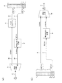
図1(a)及び図1(b)は、上記文献でKomamuraが提案したスキームと同様の、PCM互換性を持つ帯域幅拡張スキームを示している。図1(a)のエンコーダでは、帯域分割器3が、例えば96kHzのレートでサンプリングされて潜在的に周波数範囲0〜48kHzの情報を伝えるオリジナル信号2を受け取る。帯域分割器は、直交ミラーフィルタ(Quadrature Mirror Filter)のような既知の方法を使用して、各々低周波数0〜24kHzの情報と高周波数24〜48kHzの情報とを伝える低周波数(LF)信号15と高周波数(HF)信号28とに信号2を分割する。LF信号とHF信号との各々は、48kHzで、すなわちオリジナルサンプリングレートの半分のレートでサンプリングされる。HFストリームは、既知の方法を用いた損失のある圧縮4がなされて、少数ビット、例えば1、2又は3ビットを持つデータストリーム7となる。一方、LFストリームは、切り捨てられ又はノイズシェーピング5がなされて、多数ビット、例えば15、14又は13ビットを持つ信号6となる。図1(a)は、データストリーム7が3ビットを持ち、信号6が13ビットを持つ例を示している。そして、図1(a)に示すように、2つのストリームからのサンプルを、16ビットサンプル、つまりビットB1〜B16を持つ単一の複合出力ストリーム8へパックするのが直接的である。16ビット出力ストリームは、低いレート、例えば48kHzのサンプルを含み、サンプルストリーム8の再生も可能な標準需要者装置を用いて転送されかつ格納され得る。
1 (a) and 1 (b) show a bandwidth extension scheme with PCM compatibility similar to the scheme proposed by Komamura in the above document. In the encoder of FIG. 1 (a), the
Komamuraの提案は、損失のある圧縮の基礎としてADPCM(Adaptive Differential Pulse Code Modulation)を用いる。Komamuraは、24kHzのレートでHFストリームの表現を提供するために、ADPCMユニットの前にダウンサンプラを置く。この表現は次に1サンプルあたり2ビットに圧縮され、当該2ビットはシリアル化されて48kHzの1ビットストリームとなる。したがって、HF情報は最終16ビット出力のうちの1ビットのみを占め、15ビットのLF分解能を可能にする。ダウンサンプリング自体は損失のある処理であるので、Komamuraのダウンサンプラ及びADPCMユニットは、損失のある圧縮ユニット4であると考え得る。ダウンサンプリングの結果、デコーダは、48kHzまでの、又は36kHzまでの周波数の明瞭な再生を提供することができる。
Komamura's proposal uses ADPCM (Adaptive Differential Pulse Code Modulation) as the basis for lossy compression. Komamura places a downsampler in front of the ADPCM unit to provide a representation of the HF stream at a rate of 24 kHz. This representation is then compressed to 2 bits per sample and the 2 bits are serialized into a 48 kHz 1 bit stream. Thus, the HF information occupies only one bit of the final 16-bit output and allows 15-bit LF resolution. Since downsampling itself is a lossy process, the Komamura downsampler and ADPCM unit can be considered a
図1(b)は、図1(a)に対応するデコーダを示している。ここでは、ストリーム6及び7が、各々転送されたストリーム8のトップ13ビットB1〜B13及びボトム3ビットB14〜B16からアンパックされる。伸張ユニット9は、帯域分割器3によって作られたLF信号15及びHF信号28に実質的に同様のLF信号及びHF信号が帯域合成器10に送られるように、圧縮ユニット4の動作を逆転させる。帯域合成器10は、周波数範囲0〜24kHzにおけるオーディオ品質が主としてノイズシェーパ5により制限され、かつ超音波範囲24〜48kHzでは圧縮ユニット4と伸張ユニット9との結合動作により歪みが持ち込まれる、出力信号11を作るために、これら2つの信号を再結合させる。
FIG. 1B shows a decoder corresponding to FIG. Here, streams 6 and 7 are unpacked from the top 13 bits B 1 to B 13 and the bottom 3 bits B 14 to B 16 of the transferred
デコーダを持たずにストリーム8をPCMオーディオとして再生する『遺産』リスナは、主として帯域分割器からのノイズシェーピングされた(又は切り捨てられた)LF出力を耳にするが、これは、オリジナル信号2のダウンサンプリングされた低品質バージョンとして受け容れ可能であろう。しかしながら、圧縮されたHF信号7を含むストリーム8の最下位3ビットは、遺産リスナのプレーヤのオーディオ出力にも寄与する。理想圧縮器の出力はノイズ様であって、そのほか冗長を含み、原理的には改善された圧縮を与えるように除去され得るものである。実用上は、音の歪みを除去して圧縮器の出力を真にノイズ様にするように、明示的スクランブルを提供することが必要であり得る。本明細書では、もし必要なら圧縮器4がそのようなスクランブルを内部に含むものとする。これにより、その出力が統計的に独立なバイナリビットからなることを保証する。
A “legacy” listener that plays
本明細書を通じた他の仮定は、圧縮及び伸張といった処理が瞬時的であることである。実用上は、これらの処理は信号ディレイを招く。したがって、並列信号パスにディレイ補償が持ち込まれなければならない。明瞭性のために、処理ユニットの正常な動作にとって便利であり又は必要である場合には、そのようなディレイ補償は図面から省略され、同様に図面はブロック中に信号サンプリングを組織化することを妨げない。 Another assumption throughout the specification is that processes such as compression and decompression are instantaneous. In practice, these processes cause a signal delay. Therefore, delay compensation must be brought into the parallel signal path. For the sake of clarity, such delay compensation is omitted from the drawing if it is convenient or necessary for the normal operation of the processing unit, and the drawing also organizes signal sampling into blocks. I do not disturb.
負の埋め込みデータを用いた帯域幅拡張
図2(a)では、損失のある圧縮器4の出力はデータ信号であるが、図1(a)に関して説明したように、それはオーディオ信号として遺産リスナの耳にも入る。このような二重解釈は、図2(a)にて認識される。つまり、ユニット12は、実用上は存在しなくてもよいが、信号7がデータ信号とPCMオーディオ信号との二重解釈を持つことを強調するために含められており、信号7は、オーディオ信号として解釈される場合には、右詰めされたものと考えられて、16ビットワードのボトム3ビット、すなわちビットB14〜B16を占め、当該ワードの他のビットはゼロである。
Bandwidth extension using negative embedded data In FIG. 2 (a), the output of the
したがって、オーディオ信号として解釈された信号7は、減算器13へ送られる結果、ノイズシェーパ5は、出力ワード8のトップ13ビットB1〜B13に配置される、修飾された13ビット信号6’を作るために、LF信号とは逆位相で信号7を受け取る。遺産リスナは、信号6’及び7の和である、PCMオーディオ信号として解釈された出力ワード8の全体を耳にする。したがって、遺産リスナは、完全なワード8のボトム3ビットを介して直接に、またワード8のトップ13ビットにてノイズシェーパを介した逆位相で、圧縮器信号7を耳にする。したがって、これらの圧縮器信号7の2つの表現は、打ち消し合う。これは、M. A. Gerzon and P. G. Craven, “A High-Rate Buried Data Channel for Audio CD,” J. Audio Eng. Soc. Volume 43 Issue 1/2 pp. 3-22; February 1995に記載された『負の埋め込みデータ』の例である。
Thus, the
内部的には、ノイズシェーパ5は、13ビット量子化器とノイズシェーピングフィルタとを含む。圧縮器からのノイズを打ち消すのと同様に、負の埋め込みデータは、13ビット量子化器のための負のディザを提供する。加法性ノイズ以外の量子化歪みは、いまや13ビットレベルではなく、16ビットレベルである。13ビットレベルにおける加法性ノイズは、ノイズシェーピングフィルタによりシェーピングされて、潜在的に2ビット以上の知覚的利点を提供する一方、負のディザは、従来のTPDFディザよりも4.77dBだけ小さいノイズを持ち込む。ゆえに、知覚されるパフォーマンスは、TPDFディザを用いる16ビットシステムのパフォーマンスと等価である。 Internally, the noise shaper 5 includes a 13-bit quantizer and a noise shaping filter. Similar to canceling out noise from the compressor, negative embedded data provides a negative dither for the 13-bit quantizer. Quantization distortion other than additive noise is now at the 16-bit level instead of the 13-bit level. Additive noise at the 13-bit level is shaped by a noise shaping filter to potentially provide a perceptual advantage of more than 2 bits, while negative dither reduces noise by 4.77 dB less than conventional TPDF dither. Bring it in. Thus, the perceived performance is equivalent to that of a 16-bit system using TPDF dither.
対応するデコーダは、図2(b)に示されている。このデコーダは、帯域合成器10へのLF入力が、トップ13ビットのみではなくて16ビット複合信号の全体から送られることを除いて、図1(b)のデコーダと同様である。したがって、このLF信号は、信号6’及び7の結合であり、遺産リスナの耳に入るものと同様であって、リスナは負のディザと同様の利点を享受する。
The corresponding decoder is shown in FIG. This decoder is the same as the decoder of FIG. 1B except that the LF input to the
Gerzon及びCravenによる上記参考文献は、非整数ビットの他のデータをPCM信号のボトムビットの中に「埋め込む」方法をも記載している。特に、2チャンネル(ステレオ)ストリームの各チャンネルに半整数ビットを埋め込むのが直接的である。簡単のために、本明細書では整数を仮定するが、ここに記載した着想が非整数ビットの圧縮データとともに使用可能であることは明らかであろう。 The above references by Gerzon and Craven also describe how to “embed” other data of non-integer bits in the bottom bits of the PCM signal. In particular, it is straightforward to embed half integer bits in each channel of a two-channel (stereo) stream. For simplicity, integers are assumed herein, but it will be apparent that the concepts described herein can be used with non-integer bits of compressed data.
損失のない帯域幅拡張 − 一般的検討
図3(a)及び図3(b)は、各々単純な損失のない帯域幅拡張システムのためのエンコーダ及びデコーダを示している。図3(a)及び図3(b)と図1(a)及び図1(b)との間の構造的類似性は明白であるが、損失のない再生のための要求は、追加の制約を課し、かつ、損失のある場合には生じることのなかった、量子化の観点への注意深い配慮を必要とする。
Lossless Bandwidth Extension-General Considerations FIGS. 3 (a) and 3 (b) each show an encoder and decoder for a simple lossless bandwidth extension system. Although the structural similarity between FIGS. 3 (a) and 3 (b) and FIGS. 1 (a) and 1 (b) is obvious, the requirement for lossless playback is an additional constraint. And requires careful attention to the quantization point of view that would not occur if there was a loss.
損失のないシステムは情報を捨てることが許されないので、伝送チャンネルは、少なくとも伝達されるべき信号中の情報と同じ大きさの情報保持容量を持たねばならない。損失のない圧縮での経験は、16ビット以上の分解能を持つ96kHzオーディオ信号における冗長が一般に約8ビットであることを示唆している。したがって、16ビットの96kHz信号は、1サンプルあたり8ビットのデータレートに圧縮され得る。そして、24ビットの96kHz信号は、16ビットに圧縮され得る。したがって、16ビットの96kHz信号は、通常、16ビットの48kHzチャンネルを通じて転送され得る。しかしながら、それは互換性を持たない。なぜなら、最適に圧縮された信号は、PCM信号として解釈された場合には、フルスケールのホワイトノイズとして現れるからである。PCM互換性の要求は、PCM信号中への冗長を課し、したがってより大きいワード幅を必要とする。
Since a lossless system is not allowed to discard information, the transmission channel must have at least as much information holding capacity as the information in the signal to be transmitted. Experience with lossless compression suggests that the redundancy in a 96 kHz audio signal with a resolution of 16 bits or more is generally about 8 bits. Thus, a 16-
したがって、一般に、16ビットの96kHz信号を16ビットの48kHzチャンネルへ損失なしでかつPCM互換性をもってパックすることは不可能である。また、一般に、24ビットの96kHz信号を24ビットの48kHzチャンネルへ損失なしでかつPCM互換性をもってパックすることも不可能である。しかしながら、16ビットの96kHz信号の、24ビットの48kHzチャンネルへの、PCM互換性を持つ損失のないパッキングは、通常は実行可能である。
Thus, it is generally impossible to pack a 16-
現在、『96/24』(すなわち,サンプリングレート96kHz、ビット深度24ビット)が、CD(Compact Didc)の『44/16』からの次ステップとして広く認識されている。しかしながら、Gerzonによって1995年に、ノイズシェーピングにとって96kHzサンプリングが大いに有利であって、CDで広く用いられてきた44.1kHzシェーパよりも、高周波数ノイズスペクトラムにおける緩やかな上昇をもって大きい知覚的改善を可能にすることが現実化された。Gerzonの96kHzシェーパのための係数は、ほぼ5ビットの知覚的改善を提供するものであって、Acoustic Renaissance for Audio, “A Proposal for High-Quality Application of High-Density CD Carriers” private publication (1995 April); reprinted in Stereophile (1995 Aug.); in Japanese in J. Japan Audio Soc., vol. 35 (1995 Oct.); available for download at www.meridian- audio.com/araに与えられている。Stuartは、人の聴覚能力を考慮した注意深い分析を提供しており(“Coding for High-Resolution Audio Systems” J. Audio Eng. Soc., Vol. 52, No. 3, 2004 March,特に図16参照)、これから、TPDFディザをもって(ただし、ノイズシェーピングなしで)20.5ビットに適切に量子化された44.1kHzサンプリングのデジタルシステムは、配布媒体としての十分なダイナミックレンジを常に提供する、ということが結論付けられよう。96kHzサンプリングが採用される場合には、ノイズシェーピングされないときのノイズスペクトル密度が、更に3.4dBだけ低減される。適切なノイズシェーピングを伴う16ビットの96kHzチャンネルは、配布フォーマットとして全面的に適切であって、ある余裕をもってオーディオ愛好家の要求を満足する、との結論付けが可能である。
At present, “96/24” (that is,
したがって、情報理論の議論とともに音響心理学の議論を考慮すれば、24ビットのような大きいビット深度を持ち得る96kHz入力信号を、16ビットのような小さいビット深度へ再量子化することは、必要であり、かつ許容される。ゆえに、図3(a)には96kHzノイズシェーパ1が示され、『A』で識別される量子化された信号2を供給するように、不特定の分解能を持つ96kHz入力信号を、例えば17ビットに再量子化する。帯域分割器3は、損失のない分割器であって、また17ビットの低周波数出力15と、18ビットと表示された分解能を持つ高周波数出力28とを作る。ただし、18ビットの全てを与えることは、現実のオーディオ信号ではまれであろう。したがって、24ビット出力ワード16を仮定したとき、低周波数出力は出力ワード16のうちの17ビットB1〜B17を占め、残る7ビットB18〜B24は、損失のない圧縮器14で作られた、高周波数信号28の損失なしで圧縮されたバージョンである。
Therefore, considering the psychology argument as well as the information theory argument, it is necessary to re-quantize a 96 kHz input signal that can have a large bit depth such as 24 bits to a small bit depth such as 16 bits. And is acceptable. Thus, FIG. 3 (a) shows a 96
図3(b)のデコーダでは、損失のない伸張ユニット9が、高周波数信号28のレプリカとして信号28aを再生する。そして、損失のない帯域合成器10は、損失のない帯域分割器3により作られた信号15及び28と同様の信号を受け取り、その結果、信号2の損失のないレプリカとして、出力信号11を再生することができる。したがって、信号11もまた『A』で識別される。
In the decoder of FIG. 3 (b), the
量子化は損失のある処理なので、図3(a)及び図3(b)に示された全処理が損失のない処理ではあり得ず、損失がないのは、エンコーダ中の信号2からデコーダの出力11までのパスである。したがって、図3(a)及び図3(b)のエンコーダ及びデコーダにより提供される処理は、全体として、入力信号のノイズシェーピングされたバージョンを届ける。ここで、ノイズシェーピング1は、ディザを含みかつ一定のビット深度を持つオーディオ愛好家の基準を満足するように選択され得る。
Since quantization is a lossy process, the entire process shown in FIGS. 3 (a) and 3 (b) cannot be a lossless process, and there is no loss from the
「リフティング」を用いた損失のない帯域分割器及び帯域合成器
図3(a)及び図3(b)の構成は、損失のない帯域分割器3及び帯域合成器10を必要とする。ここで、『損失のない』とは、処理の中の量子化誤差を考慮に入れた、ビット的に正確な再生のことである。そのような損失のない帯域分割器及び帯域合成器を構成する方法はいくつかある。図4(a)及び図4(b)に示されたものは、「リフティング」原理に基づくものである(Calderbank, Daubechies, Sweldon and Yeo: “Wavelet Transforms That Map Integers to Integers” Applied and Computational Harmonic Analysis, vol. 5, pp 332-369 (1998),特にその図4及び図5参照)。
Lossless Band Divider and Band Synthesizer Using “Lifting” The configurations of FIGS. 3A and 3B require a
図4(a)の帯域分割器では、96kHzのような『2x』サンプリングレートでサンプリングされた入力ストリームが、各々48kHzのような『1x』サンプリングレートで奇数番サンプルと偶数番サンプルとの別個のストリームを作るためにデインターリーブされる。これら2つのストリームは、ほとんど又は全く共起関係にはなく、2xストリーム中のオリジナルの低周波数信号は、偶数ストリームに対する奇数ストリームにて、1xサンプルの半分だけ遅れて又は進んで現れる。 In the band divider of FIG. 4 (a), an input stream sampled at a “2x” sampling rate such as 96 kHz is divided into an odd numbered sample and an even numbered sample at a “1x” sampling rate such as 48 kHz. Deinterleaved to create a stream. These two streams have little or no co-occurrence relationship, and the original low frequency signal in the 2x stream appears late or advanced by half of 1x samples in the odd stream to the even stream.
ここで、2つのリフティングステップが適用される。1つのリフティングステップは、ある信号の関数を他の信号に加算する。つまり、
X’=X + f(Y)
Y’=Y
であって、これを単純に逆転させれば、
X=X’ − f(Y’)
Y=Y’
となる。これら2つの場合の間で関数fが正確に一致(状態変数の量子化又は初期化を含む。)するという条件では、損失がない。
Here, two lifting steps are applied. One lifting step adds a function of one signal to another signal. That means
X ′ = X + f (Y)
Y '= Y
And if you simply reverse this,
X = X′−f (Y ′)
Y = Y '
It becomes. There is no loss under the condition that the function f exactly matches (including quantization or initialization of the state variable) between these two cases.
図4(a)の第1のリフティングステップでは、『X』は奇数番サンプルのストリームで識別され、『Y』は偶数番サンプルのストリームで識別される。奇数ストリームから偶数ストリームを引き算すると実質的に低周波数が打ち消されるが、最善の打ち消しのためには、半サンプルシフトの修正が必要である。したがって、偶数番サンプルに半サンプルディレイを適用したい。これは、偶数のタップを持つ対称FIRフィルタによって近似され得るが、それは因果的でなく、フィルタ『f』は、実際には、あるnに対して(n+1/2)サンプルディレイを実行し、奇数パスにはnサンプルの補償ディレイが存在する。次式は、n=2で2.5サンプルのディレイを持つようなフィルタの例である。 In the first lifting step of FIG. 4A, “X” is identified by the stream of odd-numbered samples, and “Y” is identified by the stream of even-numbered samples. Subtracting the even stream from the odd stream effectively cancels the low frequency, but for the best cancellation a half sample shift correction is required. Therefore, we want to apply a half sample delay to even-numbered samples. This can be approximated by a symmetric FIR filter with an even number of taps, but it is not causal and the filter “f” actually performs a (n + 1/2) sample delay for some n, There is an n sample compensation delay in the path. The following equation is an example of a filter having a delay of 2.5 samples with n = 2.

10〜20タップの長さのフィルタが、『HF』ストリームを供給するのに妥当であり得る。このフィルタは、オリジナルスペクトラム、すなわち24kHzよりもかなり低い周波数のうちのボトム側の半分のほとんどを、良好に阻止する。 A filter with a length of 10-20 taps may be reasonable to provide an “HF” stream. This filter successfully blocks most of the bottom half of the original spectrum, i.e., much lower than 24 kHz.
2xストリームが96kHzでサンプリングされるものと再び仮定すれば、オリジナルスペクトラムのトップ側の半分は、ともにデインターリーブユニットから逆位相で現れる偶数及び奇数ストリームの双方にて、0〜24kHzにエイリアスを生じる。したがって、24〜48kHzの範囲のオリジナル信号は、第1のリフティング動作により振幅が2倍になり、1xのHF出力は、潜在的に2x入力の振幅の2倍の振幅を持つ。これは、図3(a)にてHF出力28が17ビットではなくて18ビットを持つものとして示されている理由である。
Assuming again that the 2x stream is sampled at 96 kHz, the top half of the original spectrum will alias between 0 and 24 kHz in both even and odd streams that both appear in anti-phase from the deinterleave unit. Thus, the original signal in the range of 24-48 kHz is doubled in amplitude by the first lifting operation, and the 1x HF output potentially has an amplitude twice that of the 2x input. This is the reason why the
図4(a)中の第1のリフティングステップは、奇数サンプルストリームに影響を及ぼさず、その結果、奇数サンプルストリームは、オリジナルの2xスペクトラムのトップ側及びボトム側の両半部からの信号を、同程度に伝える。第2のリフティングステップの目的は、偶数ストリームからHF出力を引き算することにより、オリジナルの高周波数情報を除去することにある。再び『半サンプルディレイ』フィルタ(実際にはn−1/2サンプル)が時間合わせのために必要とされるとともに、HF出力の2倍になった振幅を補償するために0.5をかける乗算が必要とされる。 The first lifting step in FIG. 4 (a) does not affect the odd sample stream, so that the odd sample stream receives the signals from both the top and bottom halves of the original 2x spectrum, Tell the same level. The purpose of the second lifting step is to remove the original high frequency information by subtracting the HF output from the even stream. Again a "half sample delay" filter (actually n-1 / 2 samples) is needed for time alignment and multiplication by 0.5 to compensate for the doubled amplitude of the HF output Is needed.
図4(b)は、図4(a)のリフティングステップの順序が逆転されることを、右から左への信号の流れで強調した、対応する帯域合成器を示す。1xサンプリングレートでの『奇数』及び『偶数』の結果は、2xサンプリングレートでオリジナルストリームを損失なしに再生するために、インターリーブされる。 FIG. 4 (b) shows a corresponding band synthesizer that emphasizes that the order of the lifting steps of FIG. 4 (a) is reversed with a signal flow from right to left. The “odd” and “even” results at the 1x sampling rate are interleaved to play the original stream without loss at the 2x sampling rate.
2つのリフティング動作は、1対のストリーム(LF,HF)を供給する。このストリームでは、クロスオーバー近傍のLFストリームの正確な応答は理想的でなく、カットオフ前に若干上昇し得る。これが問題であると考えられる場合には、調整されたフィルタ構造とともに3つのリフティング動作を使用することで、問題を回避し得る。 Two lifting operations provide a pair of streams (LF, HF). In this stream, the exact response of the LF stream near the crossover is not ideal and may rise slightly before cut-off. If this is considered a problem, the problem can be avoided by using three lifting operations with a tuned filter structure.
各量子化Q1,Q2は、もし帯域分割器への入力が−1から+1までの信号範囲を占める17ビット信号である場合には、オリジナルのステップサイズ、例えば2−16に一致すべきである。図4(a)における帯域分割器のLF出力及びHF出力も、そのようなオリジナルのステップサイズに量子化される。 Each quantization Q 1, Q 2 is, if when the input to the band divider is 17-bit signal occupying a signal range from -1 to +1, should match the original step size, for example 2 -16 It is. The LF output and HF output of the band divider in FIG. 4A are also quantized to such an original step size.
損失のない再生のため、デコーダ中の各量子化Q1,Q2は、エンコーダ中の対応ブロックと同様の動作、例えば両者とも切り上げ、又は両者とも切り下げという動作をしなければならない。 In order to reproduce without loss, each quantized Q 1 and Q 2 in the decoder must perform the same operation as the corresponding block in the encoder, for example, both round up or both round down.
損失のない帯域幅拡張 − 単一の互換性
図3(a)に戻って、損失のない帯域分割器3に17ビット入力が与えられるとき、その合計出力ビット数(半分のサンプリングレートで)は、17+18=35ビットであって、これは、要求される24ビット出力ワードに明らかに適合しない。
Lossless Bandwidth Extension-Single Compatibility Returning to Fig. 3 (a), when a
HF信号が潜在的に18ビットの情報を含む一方、実用上、そのピークレベルは、「力強い」商業的録音であっても、理論最大値より35dB以上も低い。損失のない圧縮がビット数を低減する手段として示されていることは、明らかである。損失のない圧縮器は、元来、可変のデータレートを作り出し、これは、実用上は、例えばFIFO(First In First Out)バッファを用いたバッファリングにより平滑化される必要がある。一般に、帯域分割により作られたHF信号は、標準オーディオ信号よりも「バースト的」に現れるので、バッファリングはより重要でさえある。明瞭性のために、図面にはここに必要なバッファが示されていないが、MLP圧縮システムの場合と同様に、損失のない圧縮器及び伸張器の各々にそのようなバッファが組み込まれていることを仮定している。もちろん、FIFOバッファリングはディレイを持ち込むので、時間合わせを維持するように、(LF信号パスのような)並列信号パスにて一定のディレイを加えることが必要である。ただし、再び明瞭性のために、そのような一定のディレイは図面から省略されている。 While the HF signal potentially contains 18 bits of information, in practice, its peak level is more than 35 dB below the theoretical maximum, even for “strong” commercial recordings. It is clear that lossless compression has been shown as a means of reducing the number of bits. A lossless compressor inherently creates a variable data rate, which in practice needs to be smoothed, for example, by buffering using a FIFO (First In First Out) buffer. In general, buffering is even more important because HF signals produced by band splitting appear “burst” than standard audio signals. For clarity, the required buffer is not shown here in the drawing, but as with the MLP compression system, such a buffer is incorporated into each of the lossless compressor and decompressor. Assume that. Of course, since FIFO buffering introduces a delay, it is necessary to add a certain delay in a parallel signal path (such as an LF signal path) so as to maintain time alignment. However, for the sake of clarity again, such constant delay has been omitted from the drawing.
商業的な96kHz録音の970例からなるコーパスに基づくテストは、0.3秒のFIFOバッファで、複合LFと損失なし圧縮HFとの情報は、もし15ビットと18ビットとの間のビット深度に量子化されるならば、97.6%のケースで24ビットに適合することを示している。 A 970 corpus-based test of a commercial 96 kHz recording is a 0.3 second FIFO buffer, and the combined LF and lossless compressed HF information is at bit depths between 15 and 18 bits. If it is quantized, it indicates that it fits 24 bits in the 97.6% case.
したがって、一般には、異なる量子化深度でのエンコーディング試行は、各アイテムがエンコードされる際に使用されるべき最大の量子化深度を確立するのに用いられ得る。96kHz量子化を粗くすることは、複合情報により必要とされるビット幅を2つの方法で低減する、すなわち、
・ 直接には、LF信号が粗く量子化されるので、
・ 間接には、HF信号が、粗く量子化される結果、少ないビットからなるので、
ということが判る。
Thus, in general, encoding attempts at different quantization depths can be used to establish the maximum quantization depth to be used when each item is encoded. Coarse 96 kHz quantization reduces the bit width required by the composite information in two ways:
Directly, since the LF signal is roughly quantized,
Indirectly, the HF signal is coarsely quantized, resulting in fewer bits,
I understand that.
しかしながら、粗い量子化は、またHF信号の中のシェーピングされたノイズを増加させる。これが重大な効果をもたらすかどうかは、HFパスの信号中でノイズが、つまり時間とともに変化し得るものが、そしていかなる時点でも損失のないエンコーダのFIFOバッファ中に格納されたデータに寄与する各瞬間で異なるものが優勢であるかどうかにかかっている。経験的に、96kHz量子化を1ビットだけ粗くすることは、48kHzでの複合情報を1.5ビットだけ低減し得ることが知られている。 However, coarse quantization also increases shaped noise in the HF signal. Whether this has a significant effect is that each moment the noise in the HF path signal can change over time and contributes to the data stored in the encoder's FIFO buffer without loss at any point in time. It depends on whether something different is dominant. Empirically, it is known that coarsening the 96 kHz quantization by 1 bit can reduce the composite information at 48 kHz by 1.5 bits.
16ビットのオリジナル素材の場合、複合情報は、しばしば24ビットに直接適合する。この場合には、図3(a)に示されている前段の量子化器は除去され得る。 For 16-bit original material, composite information often fits directly into 24 bits. In this case, the preceding quantizer shown in FIG. 3A can be eliminated.
既に示されているように、図3(b)の『A』で示されているデコーダの出力11は、同じく『A』で示されているエンコーダ中の信号2の、損失のないレプリカである。したがって、デコードされた出力11を耳にしたリスナは、単に16ビットのみへの量子化であっても20ビット量子化又は21ビット量子化と等価なノイズ密度を0〜7kHzの範囲で提供し得る、96kHzノイズシェーパの利益を享受する。
As already indicated, the
デコーダを持たない『遺産』リスナは、PCM信号として解釈されたエンコーダ出力を耳にする。したがって、主として帯域分割器のLF出力が、しかし潜在的には損失のない圧縮器の出力もが、24ビットワードのうちのボトムビットにてPCM信号として解釈される。既に言及したように、この出力は、それが未だノイズ様の信号でない場合には、ランダム化されなければならない。 A “legacy” listener without a decoder hears an encoder output interpreted as a PCM signal. Thus, mainly the LF output of the band divider, but also the potentially lossless compressor output is interpreted as a PCM signal at the bottom bit of the 24-bit word. As already mentioned, this output must be randomized if it is not yet a noise-like signal.
また、遺産リスナは、図4(a)中の量子化器Q1及びQ2によって作られる量子化歪みを体験する。これらが帯域分割器のLF出力に結合されているからである。これらの歪みは、ディザの使用により良性にされ、かつノイズシェーピングにより知覚的に低減され得る。しかしながら、損失のない再生を維持するため、図4(b)のデコーダは、その量子化器Q1及びQ2にて同様のノイズシェーピングと同様の同期したディザとを用いなければならない。更に、ノイズシェーパが状態変数を有する場合には、デコーダ及びエンコーダで同様に、これらの変数を初期化することが必要であり得る。 The heritage listener also experiences the quantization distortion created by the quantizers Q 1 and Q 2 in FIG. This is because they are coupled to the LF output of the band divider. These distortions can be made benign by the use of dither and perceptually reduced by noise shaping. However, to maintain lossless playback, the decoder of FIG. 4 (b) must use similar noise shaping and similar synchronized dither at its quantizers Q 1 and Q 2 . Further, if the noise shaper has state variables, it may be necessary to initialize these variables at the decoder and encoder as well.
二重の互換性:単純なアプローチ
図5(a)は、図3(a)及び図1(a)に示された着想を結合したエンコーダを示しており、次の3つの聴取オプションを提供する。すなわち、
・ 遺産リスナは、1xサンプリングレートで信号の13ビット表現を耳にするが、図2(a)及び図2(b)の、ノイズシェーピングの利益と負のディザの利点とは得られない、
・ 複合信号のトップ16ビットのみにアクセスするリスナは、13ビット表現の損失のある帯域幅拡張を享受するために、図1(b)のデコーダを使用し得る、
・ 全24ビットにアクセスするリスナは、『A』点にて、すなわち96kHzシェーパの結果として臨界的な周波数範囲0〜7kHzで17ビット又は18ビットの分解能をもって、13ビット信号の完全な帯域幅を持つ損失のない再生を享受するために、図5(b)のデコーダを使用し得る、
というオプションである。
Dual compatibility: simple approach FIG. 5 (a) shows an encoder combining the ideas shown in FIG. 3 (a) and FIG. 1 (a) and provides the following three listening options: . That is,
A legacy listener hears a 13-bit representation of the signal at a 1x sampling rate, but does not get the benefits of noise shaping and the negative dither of FIGS. 2 (a) and 2 (b).
A listener accessing only the top 16 bits of the composite signal may use the decoder of FIG. 1 (b) to enjoy a lossy bandwidth extension of the 13-bit representation.
• A listener accessing all 24 bits will have the full bandwidth of the 13-bit signal at point “A”, ie with a 17-bit or 18-bit resolution in the critical frequency range 0-7 kHz as a result of the 96 kHz shaper. In order to enjoy the lossless playback it has, the decoder of FIG.
It is an option.
信号『A』が13ビットに量子化されているので、帯域分割器3は、出力ワード16のトップ13ビットB1〜B13に直接に適合する13ビットのLF出力15を作るためにも構成され得る。HF出力28は、損失のある圧縮4がなされ、かつ出力ワード16の第14〜第16ビットB14〜B16へと桁合わせ12がなされる。したがって、16ビットリスナのために、出力ワード16の上位部分8は、上記2つの黒丸により与えられるように、図1(a)にて16ビットワード8が提供したのと同じデコーディングオプションを提供する。
Since the signal "A" is quantized to 13 bits, the
24ビットリスナのための損失のないエンコーディングをサポートするために、図5(a)のエンコーダと同様のエンコーダは、圧縮された信号27を供給するように、HF信号28の損失のない圧縮14を提供し得る。そして、圧縮された信号27は、出力ストリーム16の下位部分17、すなわちB17〜B24に位置する。しかしながら、エンコーダのために改善がなされて、図5(b)のデコーダ中で使用される損失のある伸張ユニット9のレプリカ9’を組み入れ、損失のない圧縮ユニット14に送られる『修整』信号を形成するようにユニット9’の出力を非圧縮のHF信号28から減算18する。損失のある圧縮及び伸張の適切な設計があれば、減算18は、損失のある圧縮された信号7が消耗するデータレートにほぼ等しい大きさだけ、圧縮された修整信号27のデータレートを低減し得る。
In order to support lossless encoding for a 24-bit listener, an encoder similar to the encoder of FIG. 5 (a) uses
図5(b)のデコーダは、修整信号のレプリカを供給するように、圧縮されたストリーム27を伸張19し、その修整信号のレプリカは、エンコーダ中の減算18を補償するために、損失のある伸張器9の出力に加算20されて、帯域分割器出力28のレプリカ28aを供給する。したがって、帯域合成器10は、帯域分割器3からの信号15及び28と同じ信号15及び28aの供給を受け、信号2の正確なレプリカ『A』である出力11を供給することができる。
The decoder of FIG. 5 (b) decompresses 19 the compressed
一般に、図5(a)に示された伸張、減算、及び損失のない圧縮は、データレートが不十分であって、修整信号を直接に提供するための損失のある圧縮器を採用することにより、修整信号のよりコンパクトな表現が通常は引き出され得る。例えば、Yuらは、損失のあるMPEG4コーデックが、MPEG−SLSとして損失のない動作に、いかにして効率良く拡張されるかを示している(Yu, Geiger, Rahardja, Herre, Lin, and Huang: “MPEG-4 Scalable to Lossless Audio Coding”, Audio Eng. Soc. 117th Convention 2004 October 28-31 San Francisco, AES preprint # 6183)。 In general, the decompression, subtraction, and lossless compression shown in FIG. 5 (a) is achieved by employing a lossy compressor that provides a modified signal directly with insufficient data rate. A more compact representation of the modified signal can usually be derived. For example, Yu et al. Show how a lossy MPEG4 codec can be efficiently extended to lossless operation as MPEG-SLS (Yu, Geiger, Rahardja, Herre, Lin, and Huang: “MPEG-4 Scalable to Lossless Audio Coding”, Audio Eng. Soc. 117th Convention 2004 October 28-31 San Francisco, AES preprint # 6183).
したがって、図6(a)では、これら全ての処理が単一の圧縮ユニット21の内部で実行されることが仮定され、圧縮ユニット21が効率良くパックされた修整信号を生成するので、別個の損失のない圧縮器の要求は生じない。逆の処理が図6(b)中の伸張ユニット22の内部で実行されることが同様に仮定され、伸張ユニット22は、標準的な損失のある圧縮された信号7と修整信号とを入力として受け取る。
Therefore, in FIG. 6 (a), it is assumed that all these processes are performed within a
したがって、ある好ましくない実施形態では、圧縮ユニット21は、図5(a)中の破線で囲まれた枠内に示された内部サブユニットを含み、同様に伸張ユニット22は、図5(b)中の破線で囲まれた枠内の内部サブユニットを含み得るが、これは次善の構成である。
Therefore, in one unfavorable embodiment, the
図6(a)及び図6(b)は、HF信号及びLF信号の各々の量子化深度の間の異なる関係をも示している。96kHz量子化は15ビットへの量子化であるが、損失のない帯域分割器のLF出力15は、単に13ビットのみへ量子化され、一方のHF出力は、18ビットへ量子化される。このような量子化深度の不均等は、図5(a)の帯域分割器のLF出力から最下位2ビットを取り、それらのビットをHFワードのボトムへ加えることにより達成され得る。より洗練された方法のためには、上記Calderbankらの文献の2.3章“Different Expansion Factors for the High and Low Pass Channels”を参照されたい。この変更は16ビットリスナの助けにはならないが、長いHFワードから引き出された修整信号が依然として8ビットに適合するように十分に圧縮されているならば、24ビットリスナは、追加2ビットの分解能の利益が得られる。
6 (a) and 6 (b) also show different relationships between the quantization depths of each of the HF signal and the LF signal. 96 kHz quantization is quantization to 15 bits, but the
本明細書及び図面では、13ビット及び15ビットのような96kHz量子化ビット深度が示されているが、それは単なる例示であって、それに限定することを意図したものではない。同じことは、96kHzの周波数自体にも言える。同様に、損失のある圧縮出力として示された3ビットは例であって、より少ないビット数への圧縮が実用上は使用可能である。 In the specification and drawings, 96 kHz quantization bit depths such as 13 bits and 15 bits are shown, but that is merely exemplary and not intended to be limiting. The same is true for the 96 kHz frequency itself. Similarly, the 3 bits shown as lossy compressed output is an example, and compression to a smaller number of bits can be used in practice.
改良された二重の互換性
図6(a)及び図6(b)のスキームは、24ビットリスナにとって優れたパフォーマンスを提供するが、遺産リスナにとって、またデコーダを持った16ビットリスナにとっては、図2(a)のエンコーダを用いた場合よりもパフォーマンスが悪くなる。図6(a)及び図6(b)は、図2(a)及び図2(b)のスキームにより提供される、LF信号をノイズシェーピングする利点と、LF信号のための負のディザとして、圧縮されたHF信号を使用する利点とを失うからである。図7(a)のエンコーダは、これらの利点を回復して、複合ワード16の次の3つの聴取可能性を提供するように設計されている。すなわち、
・ 遺産リスナにより、そのプレーヤが上位部分8を標準16ビットPCM信号として解釈する、
・ リスナにより16ビット上位部分のみが受け取られて、図2(b)のデコーダが使用される、
・ リスナにより全24ビットが受け取られて、図7(b)のデコーダが使用される、
という可能性である。
Improved Dual Compatibility The schemes of FIGS. 6 (a) and 6 (b) provide excellent performance for 24-bit listeners, but for legacy listeners and for 16-bit listeners with decoders. The performance is worse than when the encoder of FIG. FIGS. 6 (a) and 6 (b) show the advantages of noise shaping the LF signal provided by the schemes of FIGS. 2 (a) and 2 (b) and the negative dither for the LF signal, This is because the advantage of using a compressed HF signal is lost. The encoder of FIG. 7 (a) is designed to restore these advantages and provide the next three audibility of the
The heritage listener interprets the
Only the upper 16 bits are received by the listener and the decoder of FIG.
All 24 bits are received by the listener and the decoder of FIG.
That is the possibility.
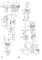
出力ワードの下位部分17とそれを供給する信号パスとを削除し、ノイズシェーピングされた分割器5’をノイズシェーパ5に置き換えるならば、図7(a)のエンコーダは、図2(a)のエンコーダと等価になるという点に注意すべきである。したがって、図2(a)及び図2(b)のスキームを参照して既になされた説明は、遺産であるか図2(b)のデコーダを使用するかにかかわらず16ビットリスナにも通用するので、これら2つの場合の正常なデコーディングが保証される。そこで、ここでは、リスナは複合ワードの全24ビットを受け取るとの仮定のもとに、図7(b)とともに図7(a)の動作に説明を集中することとする。
If the
図7(a)の新規な特徴は、ノイズシェーピングされた出力6’と、ノイズシェーピング処理で除去された情報を含む『LSB』信号23とを提供するノイズシェーピングされた分割器5’である。信号23は、出力ワード16の下位部分17のうちビットB17〜B20のいくつかへ導かれる。その結果、図7(b)のデコーダでは、信号6’及び23の双方が、ノイズシェーピングされた合成器24にて使用可能となり、当該合成器24は、信号26のレプリカとして信号26aを再生する。信号7は、図7(a)のエンコーダ中の信号15のレプリカとしてLF信号15aを供給するために、信号26aに加算25される。
The novel feature of FIG. 7 (a) is a noise shaped divider 5 ′ that provides a noise shaped
図7(b)中の伸張器22は、図6(b)の場合と同様に機能して、HF信号28の損失のない再生であるHF信号28aを提供する。したがって、損失なしで再生されたLF信号及びHF信号を受け、帯域合成器10は、信号2の損失のないレプリカとして出力信号11を再生することができる。
The
エンコーダは、複合ワードの上位部分8と下位部分17との間でLF信号15の情報を分けるので、当該エンコーダは、図6(a)のエンコーダの場合よりも高精度の96kHz信号2を扱うことができる。図7(a)及び図7(b)は、17ビットを持つ信号2に対してシステムがどのように構成されるかを示している。信号2が16ビットの場合には、信号26も16ビットを持ち、信号23は3ビットを持ち、したがって『修整(パックされた)』信号27は5ビットになる。信号2が18ビットの場合には、信号26も18ビットを持ち、信号23は5ビットを持ち、したがって『修整(パックされた)』信号27は3ビットになる。
Since the encoder divides the information of the
各々ノイズシェーピングされた分割器5’及び合成器24は、種々の方法で実装され得る。図8(a)及び図8(b)は、各々の例を提供する。
Each noise shaped divider 5 'and
図8(a)では、13ビット量子化器31は、インパルス応答がゼロ遅延項を持たず、かつ伝達関数がH(z)−1であるフィルタ33を用いて、ノイズシェーピングされる。関数Hの最適化は、文献にて広く議論されてきた。H(z)=1−0.886z−1+0.391z−2なるH(z)が1つの選択であるが、更に多くの『アグレッシブな』シェーパが、2ビット以上の知覚的改善をもたらすものとして知られている。出力6’を作るためのサブユニット30,31,32及び33の動作もまた、広く議論されてきた。
In FIG. 8A, the 13-
標準的な実務では、フィルタ33の出力が入力信号から直接に引き算される。しかしながら、ここでは、ノイズシェーピングが損失のある処理であるので、24ビットデコーダがシェーパの効果を『元に戻す』ことができなければならない。図7(b)を参照すれば、合成器24は、いずれもエンコーダの分割器5’からの出力である、『MSB』6’と『LSB』23との双方を受け取る。もしノイズシェーピングがなければ、合成器は、MSBとLSBとを(適切に桁合わせしたうえで)加算することによって、信号26を再生することができたであろう。もしノイズシェーピングからの信号修飾がLSBの決定関数であるなら、合成器は、入力26を再生することもできる。もしHが、量子化された係数を持つ有限インパルス応答フィルタであるなら、当該修飾が決定的であるように準備することは、最も容易である。更に、このフィルタ33の出力は、入力と同じビット幅に、すなわち図示のように17ビットに量子化36がなされるべきである。さもなければ、LSB出力のビット幅は増加するであろう。更にまた、17ビットレベルでのディザリングがなされない量子化歪みが遺産リスナ及び16ビットリスナの耳に入る信号に持ち込まれることを回避するため、17ビットへの量子化は、ディザリング35がなされるべきである。このディザは決定的でなければならず、またディザ生成器35,35aは、エンコーダとデコーダとの間で同期していなければならない。
In standard practice, the output of the
これらの条件が与えられるなら、図8(b)の合成器は、ユニット33a,34a,35a,36aにて、『LSB』信号23から、図8(a)の分割器にてユニット33,34,35及び36により作られたノイズシェーピング修飾38のレプリカ38aを作ることができる。加算器32aは、量子化器3’により信号37から取り出された下位ビット23を加算し、加算器30aは、減算器30の効果を補償し、これにより信号26のレプリカ26aを作る。
Given these conditions, the synthesizer of FIG. 8 (b) uses the
図7(a)及び図7(b)に戻って、信号2のビット数が16ビットよりも少ない場合には、システムは、次のようにして改善され得る。すなわち、ノイズシェーピングされた分割器5’は16ビット入力26を受け取るように構成され、その結果、その16ビットのうちのボトムビットは、減算器13により持ち込まれる符号が逆転される点を除いて、対応するボトムビットの圧縮された信号7のみを含み得る。図8(a)では、これらのビットもまた、分割器を通して伝播し、ノイズシェーピング修飾38が引き算されている点を除いて、信号23の中に現れる。ゆえに、その信号38の情報を持つデコーダは、これらのビットを推論し得る。したがって、これらのビットは、信号7及び信号23の両者において二重に、複合ワードへ効果的に提供される。このため、エンコーダは、信号23から冗長なビットを除去するように変形され得る。このとき、デコーダは、除去されたビットを回復する。信号2が15ビット信号の場合には、『LSB』信号23から最下位の1ビットのみがエンコーダにより除去され、その1ビットは、
− 図8(b)中の信号38aの最下位ビット出力と、
− 図7(b)中の信号7の最下位ビットと
の排他的ORとして回復され得る。
Returning to FIGS. 7 (a) and 7 (b), if the number of bits of
The least significant bit output of
It can be recovered as an exclusive OR with the least significant bit of
この処理は、再帰的である。なぜなら、このようにしてある特定のサンプリング時に引き出された、回復された分割器LSBは、ノイズシェーピングフィルタ33aを通した伝播のゆえに、次のサンプリング時に信号38aに影響を及ぼすからである。したがって、ノイズシェーピングフィルタ33及び33aの中の各々の状態変数が同じ値に初期化されることを、保証することが必要である。ストリームの開始時に、エンコーダ及びデコーダの双方にて、これらの変数をゼロに設定するのが自然であろう。
This process is recursive. This is because the recovered divider LSB extracted in this way at a particular sampling affects the
エンコードされた複合ワードのうちの下位部分の割り付けは、実装者の裁量による。例えば、シェーパからのLSBとパックされた修整信号とは、全体動作にいかなる効果をも及ぼすことなく、交換され得る。図9は、破線で囲まれた枠内に示されたように、出力複合ワードの上位部分8を直接に提供する16ビット信号29を供給する分割器を組み入れた、エンコーダの関連部分を示している。解析により、図7(a)中の対応する要素12,13及び5’を図9に置き換えれば、複合ワード16に何の変更もないことが判る。当業者ならば、ステップサイズが必ずしも正確な2のべき乗によらない量子化に、量子化1及び31が置き換えられ得ることをも実現するであろう。この場合には、信号のうちのいくつかはバイナリでなくn値であって、最高効率のために、これらの信号は、複合ワードの中にエントロピ符号化がなされ得る。しかしながら、PCM互換性のため、『MSB』信号6’は、標準バイナリフォーマットにて整数として表現され、かつエントロピ符号化がなされないべきである。
The allocation of the lower part of the encoded compound word is at the discretion of the implementer. For example, the LSB from the shaper and the packed modification signal can be exchanged without any effect on the overall operation. FIG. 9 shows the relevant part of the encoder incorporating a divider supplying a 16-
ある状況にて、20ビットオーディオなら伝達可能であるが、24ビットオーディオは伝達不可能であるという事態を考慮すれば、三重の互換性を提供するとの要求もあり得る。すなわち、24ビットリスナのための損失のない拡張された帯域幅再生を提供するだけでなく、遺産リスナと、デコーダを持つ16ビットリスナと、デコーダを持つ20ビットリスナとの間のバランスした利点をも提供するとの要求である。これは、24ビット複合ワードのうちの下位部分の更なる細分と、既に説明した原理の更なる応用とによって、達成され得る。 In certain circumstances, considering the situation that 20-bit audio can be transmitted but 24-bit audio cannot be transmitted, there may be a requirement to provide triple compatibility. That is, not only provides lossless extended bandwidth recovery for 24-bit listeners, but also provides a balanced advantage between legacy listeners, 16-bit listeners with decoders, and 20-bit listeners with decoders. Is also a request to provide. This can be achieved by further subdivision of the lower part of the 24-bit compound word and further application of the principles already described.
本明細書における16ビット及び24ビットへの参照は、単に現在の実務で一般的なワード幅を反映したものであって、本発明は、これより長い又は短いワード幅の、異なるワード幅の値であっても、等しく好適に適用され得る。 References to 16-bit and 24-bit in this specification simply reflect word widths that are common in current practice, and the present invention provides different word width values for longer or shorter word widths. Even so, it can be applied equally favorably.
以上を要約すれば、様々なデコーディングオプションとともにPCM互換性を持つストリームを提供するシステムを説明してきた。オリジナルの高サンプリングレート信号の損失のない再生を実現するためにはデコーダが必要であり、したがって遺産リスナに提供される信号は「損失のある」信号であると説明したが、損失のある信号への減縮は、時不変のフィルタリング動作と、サンプリングレート低減動作と、時不変のノイズフロアを課す再量子化動作とを用いるだけで、オーディオ愛好家仲間で「良性」であると称される態様で実行される。 In summary, a system that provides PCM compatible streams with various decoding options has been described. It was explained that a decoder is needed to achieve lossless reproduction of the original high sampling rate signal, so the signal provided to the legacy listener is a "lossy" signal, but to the lossy signal Is a mode called "benign" among audio enthusiasts, using only time-invariant filtering operations, sampling rate reduction operations, and re-quantization operations that impose a time-invariant noise floor. Executed.
Claims (25)
前記複数のサンプル(16)の各々は、上位部分(8)と下位部分(17)とを持ち、
前記上位部分(8)と前記下位部分(17)とは、いずれも、第1のデコーダが損失なしで前記入力デジタルオーディオ信号(2)を再生できるようにする情報を含み、
標準PCMストリームとして解釈されたとき、前記上位部分(8)は、低減された帯域幅を持つ前記入力デジタルオーディオ信号のバージョンの第1の損失のある表現を提供し、
前記上位部分(8)は、前記第1の損失のある表現の帯域幅よりも大きい帯域幅を持つ前記入力デジタルオーディオ信号の第2の損失のある表現を第2のデコーダが再生できるようにする情報を含み、
前記入力デジタルオーディオ信号(2)は、高周波数出力(28)と低周波数出力(15)とを持つ損失のない帯域分割器(3)に結合され、前記高周波数出力(28)は、損失のある圧縮出力(7)と復元出力(27)とを持つ圧縮ユニット(21)に結合され、
前記上位部分(8)は、前記低周波数出力(15)及び前記損失のある圧縮出力(7)に応じて引き出され、前記下位部分(17)は、前記復元出力(27)に応じて引き出されるオーディオエンコーダ。 A PCM digital audio output that receives an input digital audio signal (2) at a first sampling rate and then has a plurality of samples (16) and a second sampling rate that is lower than the first sampling rate. A lossless audio encoder configured to generate
Each of the plurality of samples (16) has an upper part (8) and a lower part (17);
The upper part (8) and the lower part (17) both comprise information that allows the first decoder to reproduce the input digital audio signal (2) without loss,
When interpreted as a standard PCM stream, the upper part (8) provides a first lossy representation of the version of the input digital audio signal with reduced bandwidth;
The upper part (8) enables a second decoder to reproduce a second lossy representation of the input digital audio signal having a bandwidth greater than the bandwidth of the first lossy representation. Including information,
The input digital audio signal (2) is coupled to a lossless band divider (3) having a high frequency output (28) and a low frequency output (15), the high frequency output (28) Coupled to a compression unit (21) having a compression output (7) and a decompression output (27),
The upper part (8) is extracted according to the low frequency output (15) and the lossy compressed output (7), and the lower part (17) is extracted according to the restored output (27). Audio encoder.
前記第1の損失のある表現は、時不変のフィルタリングと、サンプリングレートの低減と、時不変のノイズフロアを課す再量子化とのうちの1つ以上のみにかけられた、前記入力デジタルオーディオ信号(2)に対応する表現であるオーディオエンコーダ。 The lossless audio encoder according to claim 1.
The first lossy representation is the input digital audio signal (Q) that has been subjected to only one or more of time-invariant filtering, sampling rate reduction, and re-quantization imposing a time-invariant noise floor. An audio encoder which is an expression corresponding to 2).
各上位部分は、16バイナリビットからなるオーディオエンコーダ。 The lossless audio encoder according to claim 1 or 2,
Each upper part is an audio encoder consisting of 16 binary bits.
各下位部分は、8バイナリビットからなるオーディオエンコーダ。 The lossless audio encoder according to any one of claims 1 to 3 ,
Each lower part is an audio encoder consisting of 8 binary bits.
前記第2のサンプリングレートは、前記第1のサンプリングレートの半分であるオーディオエンコーダ。 The lossless audio encoder according to any one of claims 1 to 4 ,
The audio encoder, wherein the second sampling rate is half of the first sampling rate.
前記第2のサンプリングレートは、48kHzであるオーディオエンコーダ。 The lossless audio encoder according to any one of claims 1 to 5,
The audio encoder, wherein the second sampling rate is 48 kHz.
前記第2のサンプリングレートは、44.1kHzであるオーディオエンコーダ。 The lossless audio encoder according to any one of claims 1 to 5,
The audio encoder, wherein the second sampling rate is 44.1 kHz.
前記第2のデコーダは、前記第1のサンプリングレートに対応するナイキスト周波数に等しいオーディオ帯域幅を再生するオーディオエンコーダ。 The lossless audio encoder according to any one of claims 1 to 7,
The second decoder is an audio encoder that reproduces an audio bandwidth equal to a Nyquist frequency corresponding to the first sampling rate.
前記第2のデコーダは、前記第1のサンプリングレートに対応するナイキスト周波数の4分の3に等しい帯域幅を再生するオーディオエンコーダ。 The lossless audio encoder according to any one of claims 1 to 7,
The second decoder is an audio encoder that reproduces a bandwidth equal to three quarters of the Nyquist frequency corresponding to the first sampling rate.
前記圧縮ユニット(21)は、前記損失のある圧縮出力(7)に結合された出力を持つ、損失のある圧縮ユニット(4)を備えたオーディオエンコーダ。 The lossless audio encoder according to any one of claims 1 to 9 ,
The audio encoder comprising a lossy compression unit (4), the compression unit (21) having an output coupled to the lossy compression output (7).
前記圧縮ユニット(21)は、前記損失のある圧縮ユニット(4)に結合された入力と、前記復元出力(27)に結合された出力とを持つ、損失のない圧縮ユニット(14)を更に備えたオーディオエンコーダ。 The lossless audio encoder of claim 10.
The compression unit (21) further comprises a lossless compression unit (14) having an input coupled to the lossy compression unit (4) and an output coupled to the decompressed output (27). Audio encoder.
前記下位部分(17)は、前記損失のない帯域分割器(3)の低周波数出力(15)に応じて引き出されるオーディオエンコーダ。 The lossless audio encoder according to any one of claims 1 to 11 ,
The lower part (17) is an audio encoder extracted according to the low frequency output (15) of the lossless band divider (3).
前記損失のない帯域分割器(3)の低周波数出力(15)は、前記上位部分(8)に結合された第1の出力(6’)と、前記下位部分(17)に結合された第2の出力(23)とを持つ分割器(5’)に結合されているオーディオエンコーダ。 The lossless audio encoder according to any one of claims 1 to 12 ,
The low frequency output (15) of the lossless band divider (3) has a first output (6 ′) coupled to the upper part (8) and a first output coupled to the lower part (17). Audio encoder coupled to a divider (5 ') with two outputs (23).
前記分割器(5’)は、ノイズシェーピングフィルタを備えたオーディオエンコーダ。 The lossless audio encoder of claim 13.
The divider (5 ′) is an audio encoder provided with a noise shaping filter.
前記上位部分(8)の中の複数のビットは、前記損失のない帯域分割器(3)の前記低周波数出力(15)に結合された第1の入力と、前記損失のある圧縮出力(7)に結合された第2の入力とを持つ減算器(13)の出力に応じて引き出されるオーディオエンコーダ。 The lossless audio encoder according to any one of claims 1 to 14 ,
A plurality of bits in the upper part (8) are coupled to a first input coupled to the low frequency output (15) of the lossless band divider (3) and the lossy compressed output (7 And an audio encoder that is derived in response to the output of a subtractor (13) having a second input coupled thereto.
前記装置は、コンフィギュレーションパラメータに応じてエンコーディングを実行し、かつ、前記ウォーターマークエンコーダは、デコーダによる使用のために前記ウォーターマーク出力の中に前記コンフィギュレーションパラメータを埋め込む装置。 16. A device comprising a lossless audio encoder according to any one of the preceding claims, coupled to a lossless reversible watermark encoder for supplying a watermark output.
The apparatus performs encoding in response to a configuration parameter, and the watermark encoder embeds the configuration parameter in the watermark output for use by a decoder.
前記損失のないオーディオエンコーダの入力に量子化された信号を供給するノイズシェーパを更に備え、
前記ノイズシェーパは、あるビット深度まで量子化し、前記コンフィギュレーションパラメータは、前記ビット深度を含む装置。 The apparatus of claim 17.
A noise shaper for supplying a quantized signal to the input of the lossless audio encoder;
The noise shaper quantizes to a certain bit depth, and the configuration parameter includes the bit depth.
前記下位部分の情報保持容量を超えないようにオーディオ品質を最大化するために、前記量子化のビット深度を選択する選択ユニットを更に備えた装置。 The apparatus of claim 18.
The apparatus further comprises a selection unit for selecting the quantization bit depth in order to maximize the audio quality so as not to exceed the information holding capacity of the lower part.
前記オーディオデコーダは、前記PCM入力デジタルオーディオ信号から、前記第2のサンプリングレートよりも高い第1のサンプリングレートを持つ出力デジタルオーディオ信号(11)を生成するように更に構成され、
前記出力デジタルオーディオ信号と比較信号との間の差違は、0〜5kHzの周波数範囲で、静的な統計でスペクトル的にシェーピングされたノイズであって、前記比較信号は、前記入力デジタルオーディオ信号から、フィルタリングの動作及び前記第1のサンプリングレートへのリサンプリングの動作により生成され、
前記出力デジタルオーディオ信号と第2の出力信号との間の差違は、0〜5kHzの周波数範囲で、静的な統計でスペクトル的にシェーピングされたノイズであって、前記第2の出力信号は、前記オーディオデコーダに送られるとき、各サンプルから下位部分を除去する以外は前記PCM入力デジタルオーディオ信号と一致する信号から作られ、
前記出力デジタルオーディオ信号(11)は、前記オーディオエンコーダに提供されたデジタルオーディオ入力信号(2)の正確なレプリカであるオーディオデコーダ。 An audio decoder configured to receive a PCM input digital audio signal having a plurality of input samples (16) generated at a second sampling rate by a corresponding audio encoder according to claim 1,
The audio decoder is further configured to generate an output digital audio signal (11) having a first sampling rate higher than the second sampling rate from the PCM input digital audio signal;
The difference between the output digital audio signal and the comparison signal is noise that is spectrally shaped with static statistics and in the frequency range of 0 to 5 kHz, and the comparison signal is derived from the input digital audio signal. Generated by a filtering operation and a resampling operation to the first sampling rate,
The difference between the output digital audio signal and the second output signal is noise that is spectrally shaped with static statistics in the frequency range of 0 to 5 kHz, wherein the second output signal is: When sent to the audio decoder, it is made from a signal that matches the PCM input digital audio signal, except removing the sub-portion from each sample,
The audio decoder, wherein the output digital audio signal (11) is an exact replica of the digital audio input signal (2) provided to the audio encoder.
前記オーディオデコーダは、
高周波数入力(28a)と低周波数入力(15)とを持ち、前記出力デジタルオーディオ信号(11)を供給する、損失のない帯域合成器(10)と、
損失のある入力(7)と、復元入力(27)と、出力(28a)とを持ち、前記出力は前記損失のない帯域合成器(10)の前記高周波数入力に結合された伸張ユニット(22)とを備え、
各入力サンプル(16)は、上位部分(8)と下位部分(17)とを有し、
前記損失のない帯域合成器(10)の前記低周波数入力(15)は、前記上位部分(8)に応じて引き出され、
前記伸張ユニット(22)の前記損失のある入力(7)は、前記上位部分(8)に応じて、かつ前記下位部分(17)から独立して引き出され、
前記伸張ユニット(22)の前記復元入力(27)は、前記下位部分(17)に応じて、かつ前記上位部分(8)から独立して引き出されるオーディオデコーダ。 An output digital audio signal (11) that receives a PCM input digital audio signal having a plurality of input samples (16) at a second sampling rate and has a first sampling rate that is higher than the second sampling rate. An audio decoder configured to generate
The audio decoder
A lossless band synthesizer (10) having a high frequency input (28a) and a low frequency input ( 15 ) and supplying the output digital audio signal (11);
A decompression unit (22) having a lossy input (7), a restoration input (27), and an output (28a) coupled to the high frequency input of the lossless band synthesizer (10). )
Each input sample (16) has an upper part (8) and a lower part (17),
The low frequency input (15) of the lossless band synthesizer (10) is derived according to the upper part (8),
The lossy input (7) of the expansion unit ( 22 ) is derived in response to the upper part (8) and independently from the lower part (17);
The audio decoder, wherein the decompression input (27) of the decompression unit ( 22 ) is derived according to the lower part (17) and independently from the upper part (8).
前記損失のない帯域合成器(10)の前記低周波数入力(15)は、前記上位部分(8)の中に含まれる全ビットに応じて引き出されるオーディオデコーダ。 The audio decoder according to claim 21, wherein
An audio decoder in which the low frequency input (15) of the lossless band synthesizer (10) is derived according to all bits contained in the upper part (8).
前記損失のない帯域合成器(10)の前記低周波数入力(15)もまた、前記下位部分(17)に応じているオーディオデコーダ。 The audio decoder according to claim 21 or 22,
Audio decoder wherein the low frequency input (15) of the lossless band synthesizer (10) is also responsive to the sub-portion (17).
前記出力デジタルオーディオ信号(11)と比較信号との間の差違は、0〜5kHzの周波数範囲で、静的な統計でスペクトル的にシェーピングされたノイズであって、前記比較信号は、前記PCM入力デジタルオーディオ信号から、フィルタリングの動作及び前記第1のサンプリングレートへのリサンプリングの動作により生成されるオーディオデコーダ。 The audio decoder according to any one of claims 21 to 23,
The difference between the output digital audio signal (11) and the comparison signal is noise that is spectrally shaped with static statistics and in the frequency range of 0 to 5 kHz, the comparison signal being the PCM input An audio decoder generated from a digital audio signal by a filtering operation and a resampling operation to the first sampling rate.
対応するオーディオエンコーダにより生成された信号を受け取るように構成され、
前記出力デジタルオーディオ信号(11)は、前記対応するオーディオエンコーダに提供されたデジタルオーディオ入力信号(2)の正確なレプリカであるオーディオデコーダ。 The audio decoder according to any one of claims 21 to 24,
Configured to receive a signal generated by a corresponding audio encoder;
The audio decoder, wherein the output digital audio signal (11) is an exact replica of the digital audio input signal (2) provided to the corresponding audio encoder.
Applications Claiming Priority (3)
| Application Number | Priority Date | Filing Date | Title |
|---|---|---|---|
| GBGB1210373.5A GB201210373D0 (en) | 2012-06-12 | 2012-06-12 | Doubly compatible lossless audio sandwidth extension |
| GB1210373.5 | 2012-06-12 | ||
| PCT/GB2013/051548 WO2013186561A2 (en) | 2012-06-12 | 2013-06-12 | Doubly compatible lossless audio bandwidth extension |
Publications (3)
| Publication Number | Publication Date |
|---|---|
| JP2015519615A JP2015519615A (en) | 2015-07-09 |
| JP2015519615A5 JP2015519615A5 (en) | 2016-08-04 |
| JP6264699B2 true JP6264699B2 (en) | 2018-01-24 |
Family
ID=46605804
Family Applications (1)
| Application Number | Title | Priority Date | Filing Date |
|---|---|---|---|
| JP2015516683A Active JP6264699B2 (en) | 2012-06-12 | 2013-06-12 | Lossless audio bandwidth expansion with dual compatibility |
Country Status (8)
| Country | Link |
|---|---|
| US (1) | US9548055B2 (en) |
| EP (1) | EP2859548B1 (en) |
| JP (1) | JP6264699B2 (en) |
| KR (1) | KR102202833B1 (en) |
| CN (1) | CN104508740B (en) |
| CA (1) | CA2898923C (en) |
| GB (3) | GB201210373D0 (en) |
| WO (1) | WO2013186561A2 (en) |
Families Citing this family (22)
| Publication number | Priority date | Publication date | Assignee | Title |
|---|---|---|---|---|
| GB2524682B (en) * | 2011-10-24 | 2016-04-27 | Graham Craven Peter | Lossless buried data |
| GB201210373D0 (en) | 2012-06-12 | 2012-07-25 | Meridian Audio Ltd | Doubly compatible lossless audio sandwidth extension |
| EP2980795A1 (en) * | 2014-07-28 | 2016-02-03 | Fraunhofer-Gesellschaft zur Förderung der angewandten Forschung e.V. | Audio encoding and decoding using a frequency domain processor, a time domain processor and a cross processor for initialization of the time domain processor |
| GB2547877B (en) * | 2015-12-21 | 2019-08-14 | Graham Craven Peter | Lossless bandsplitting and bandjoining using allpass filters |
| GB2546963B (en) * | 2015-12-23 | 2020-10-21 | Law Malcolm | Transparent lossless audio watermarking enhancement |
| KR101968456B1 (en) | 2016-01-26 | 2019-04-11 | 돌비 레버러토리즈 라이쎈싱 코오포레이션 | Adaptive quantization |
| CN106205627B (en) * | 2016-07-14 | 2019-10-18 | 暨南大学 | Digital audio reversible water mark algorithm based on side information prediction and histogram translation |
| CN106528040A (en) * | 2016-11-02 | 2017-03-22 | 福建星网视易信息系统有限公司 | Method and apparatus for improving audio quality of android device |
| US10354668B2 (en) | 2017-03-22 | 2019-07-16 | Immersion Networks, Inc. | System and method for processing audio data |
| EP3483882A1 (en) | 2017-11-10 | 2019-05-15 | Fraunhofer-Gesellschaft zur Förderung der angewandten Forschung e.V. | Controlling bandwidth in encoders and/or decoders |
| EP3483884A1 (en) | 2017-11-10 | 2019-05-15 | Fraunhofer-Gesellschaft zur Förderung der angewandten Forschung e.V. | Signal filtering |
| EP3483886A1 (en) | 2017-11-10 | 2019-05-15 | Fraunhofer-Gesellschaft zur Förderung der angewandten Forschung e.V. | Selecting pitch lag |
| EP3483880A1 (en) | 2017-11-10 | 2019-05-15 | Fraunhofer-Gesellschaft zur Förderung der angewandten Forschung e.V. | Temporal noise shaping |
| EP3483878A1 (en) | 2017-11-10 | 2019-05-15 | Fraunhofer-Gesellschaft zur Förderung der angewandten Forschung e.V. | Audio decoder supporting a set of different loss concealment tools |
| WO2019091576A1 (en) * | 2017-11-10 | 2019-05-16 | Fraunhofer-Gesellschaft zur Förderung der angewandten Forschung e.V. | Audio encoders, audio decoders, methods and computer programs adapting an encoding and decoding of least significant bits |
| EP3483879A1 (en) | 2017-11-10 | 2019-05-15 | Fraunhofer-Gesellschaft zur Förderung der angewandten Forschung e.V. | Analysis/synthesis windowing function for modulated lapped transformation |
| WO2019091573A1 (en) | 2017-11-10 | 2019-05-16 | Fraunhofer-Gesellschaft zur Förderung der angewandten Forschung e.V. | Apparatus and method for encoding and decoding an audio signal using downsampling or interpolation of scale parameters |
| EP3483883A1 (en) | 2017-11-10 | 2019-05-15 | Fraunhofer-Gesellschaft zur Förderung der angewandten Forschung e.V. | Audio coding and decoding with selective postfiltering |
| US20200150643A1 (en) * | 2018-05-07 | 2020-05-14 | Strong Force Iot Portfolio 2016, Llc | Methods and systems for data collection, learning, and streaming of machine signals for analytics and maintenance using the industrial internet of things |
| US20210127125A1 (en) * | 2019-10-23 | 2021-04-29 | Facebook Technologies, Llc | Reducing size and power consumption for frame buffers using lossy compression |
| CN115512711A (en) * | 2021-06-22 | 2022-12-23 | 腾讯科技(深圳)有限公司 | Speech coding, speech decoding method, apparatus, computer device and storage medium |
| CN116974453B (en) * | 2023-09-25 | 2023-12-08 | 北京灵汐科技有限公司 | Signal processing method, signal processing device, signal processor, apparatus, and medium |
Family Cites Families (23)
| Publication number | Priority date | Publication date | Assignee | Title |
|---|---|---|---|---|
| EP0400222A1 (en) * | 1989-06-02 | 1990-12-05 | ETAT FRANCAIS représenté par le Ministère des Postes, des Télécommunications et de l'Espace | Digital transmission system using subband coding of a digital signal |
| US5596647A (en) * | 1993-06-01 | 1997-01-21 | Matsushita Avionics Development Corporation | Integrated video and audio signal distribution system and method for use on commercial aircraft and other vehicles |
| JP3312538B2 (en) * | 1995-08-18 | 2002-08-12 | 日本ビクター株式会社 | Sound signal processing device |
| US5956674A (en) * | 1995-12-01 | 1999-09-21 | Digital Theater Systems, Inc. | Multi-channel predictive subband audio coder using psychoacoustic adaptive bit allocation in frequency, time and over the multiple channels |
| EP0798866A2 (en) * | 1996-03-27 | 1997-10-01 | Kabushiki Kaisha Toshiba | Digital data processing system |
| JPH09261068A (en) * | 1996-03-27 | 1997-10-03 | Toshiba Corp | Data compression/decoding/transmission/reception/ recording/reproduction method and device |
| JP3405109B2 (en) * | 1996-04-17 | 2003-05-12 | 日本ビクター株式会社 | Encoding device, decoding device, recording medium, and digital audio signal reproducing device |
| KR100251453B1 (en) * | 1997-08-26 | 2000-04-15 | 윤종용 | High quality coder & decoder and digital multifuntional disc |
| US6226616B1 (en) | 1999-06-21 | 2001-05-01 | Digital Theater Systems, Inc. | Sound quality of established low bit-rate audio coding systems without loss of decoder compatibility |
| JP2003280694A (en) * | 2002-03-26 | 2003-10-02 | Nec Corp | Hierarchical lossless coding and decoding method, hierarchical lossless coding method, hierarchical lossless decoding method and device therefor, and program |
| US7424434B2 (en) * | 2002-09-04 | 2008-09-09 | Microsoft Corporation | Unified lossy and lossless audio compression |
| US7395210B2 (en) * | 2002-11-21 | 2008-07-01 | Microsoft Corporation | Progressive to lossless embedded audio coder (PLEAC) with multiple factorization reversible transform |
| JP4679049B2 (en) * | 2003-09-30 | 2011-04-27 | パナソニック株式会社 | Scalable decoding device |
| KR101243412B1 (en) * | 2004-03-25 | 2013-03-13 | 디티에스, 인코포레이티드 | Lossless multi-channel audio codec |
| US7392195B2 (en) * | 2004-03-25 | 2008-06-24 | Dts, Inc. | Lossless multi-channel audio codec |
| US20070078645A1 (en) * | 2005-09-30 | 2007-04-05 | Nokia Corporation | Filterbank-based processing of speech signals |
| EP1852848A1 (en) * | 2006-05-05 | 2007-11-07 | Deutsche Thomson-Brandt GmbH | Method and apparatus for lossless encoding of a source signal using a lossy encoded data stream and a lossless extension data stream |
| EP1852849A1 (en) * | 2006-05-05 | 2007-11-07 | Deutsche Thomson-Brandt Gmbh | Method and apparatus for lossless encoding of a source signal, using a lossy encoded data stream and a lossless extension data stream |
| EP1883067A1 (en) | 2006-07-24 | 2008-01-30 | Deutsche Thomson-Brandt Gmbh | Method and apparatus for lossless encoding of a source signal, using a lossy encoded data stream and a lossless extension data stream |
| MX2011000370A (en) * | 2008-07-11 | 2011-03-15 | Fraunhofer Ges Forschung | An apparatus and a method for decoding an encoded audio signal. |
| ES2645415T3 (en) * | 2009-11-19 | 2017-12-05 | Telefonaktiebolaget Lm Ericsson (Publ) | Methods and provisions for volume and sharpness compensation in audio codecs |
| US8374858B2 (en) * | 2010-03-09 | 2013-02-12 | Dts, Inc. | Scalable lossless audio codec and authoring tool |
| GB201210373D0 (en) | 2012-06-12 | 2012-07-25 | Meridian Audio Ltd | Doubly compatible lossless audio sandwidth extension |
-
2012
- 2012-06-12 GB GBGB1210373.5A patent/GB201210373D0/en not_active Ceased
-
2013
- 2013-06-12 JP JP2015516683A patent/JP6264699B2/en active Active
- 2013-06-12 KR KR1020157000750A patent/KR102202833B1/en active IP Right Grant
- 2013-06-12 US US14/406,110 patent/US9548055B2/en active Active
- 2013-06-12 EP EP13733412.4A patent/EP2859548B1/en active Active
- 2013-06-12 CA CA2898923A patent/CA2898923C/en active Active
- 2013-06-12 CN CN201380038662.1A patent/CN104508740B/en active Active
- 2013-06-12 WO PCT/GB2013/051548 patent/WO2013186561A2/en active Application Filing
- 2013-06-12 GB GB1310486.4A patent/GB2503110B/en active Active
- 2013-06-13 GB GBGB1310497.1A patent/GB201310497D0/en not_active Ceased
Also Published As
| Publication number | Publication date |
|---|---|
| US9548055B2 (en) | 2017-01-17 |
| GB201210373D0 (en) | 2012-07-25 |
| GB2503110B (en) | 2016-06-15 |
| WO2013186561A3 (en) | 2014-02-27 |
| CA2898923A1 (en) | 2013-12-19 |
| KR20150032699A (en) | 2015-03-27 |
| GB201310497D0 (en) | 2013-07-24 |
| US20150154969A1 (en) | 2015-06-04 |
| CN104508740A (en) | 2015-04-08 |
| EP2859548A2 (en) | 2015-04-15 |
| GB201310486D0 (en) | 2013-07-24 |
| CN104508740B (en) | 2017-08-11 |
| EP2859548B1 (en) | 2018-01-31 |
| JP2015519615A (en) | 2015-07-09 |
| GB2503110A (en) | 2013-12-18 |
| WO2013186561A2 (en) | 2013-12-19 |
| CA2898923C (en) | 2021-03-16 |
| KR102202833B1 (en) | 2021-01-14 |
Similar Documents
| Publication | Publication Date | Title |
|---|---|---|
| JP6264699B2 (en) | Lossless audio bandwidth expansion with dual compatibility | |
| JP2015519615A5 (en) | ||
| ES2537820T3 (en) | Scalable lossless audio codec and authoring tool | |
| KR101135726B1 (en) | Encoder, decoder, encoding method, decoding method, and recording medium | |
| US8374858B2 (en) | Scalable lossless audio codec and authoring tool | |
| JP4997098B2 (en) | Scalable reversible audio codec and authoring tool | |
| JP2009536363A (en) | Method and apparatus for lossless encoding of a source signal using a lossy encoded data stream and a lossless extended data stream | |
| KR20020002241A (en) | Digital audio system | |
| KR100891666B1 (en) | Apparatus for processing audio signal and method thereof | |
| US20060212614A1 (en) | Cd playback augmentation for higher resolution and multi-channel sound | |
| JP3304750B2 (en) | Lossless encoder, lossless recording medium, lossless decoder, and lossless code decoder | |
| JP2007142547A (en) | Coding method and decoding method, and coder and decoder employing same | |
| JP3304739B2 (en) | Lossless encoder, lossless recording medium, lossless decoder, and lossless code decoder | |
| KR20040086879A (en) | Method and apparatus for encoding/decoding audio data using bandwidth extension technology | |
| KR100433984B1 (en) | Method and Apparatus for Encoding/decoding of digital audio | |
| JP2001337698A (en) | Coding device, coding method, decoding device and decoding method | |
| JP2003304158A (en) | Method and device for reproducing signal, method and device for recording signal, and method and device for generating code string | |
| JP2004094090A (en) | System and method for compressing and expanding audio signal | |
| JP2003308013A (en) | Data conversion method, data converting apparatus, data reconstruction method, data reconstructing apparatus, data format, recording medium, and program |
Legal Events
| Date | Code | Title | Description |
|---|---|---|---|
| A521 | Request for written amendment filed |
Free format text: JAPANESE INTERMEDIATE CODE: A821 Effective date: 20150216 |
|
| RD01 | Notification of change of attorney |
Free format text: JAPANESE INTERMEDIATE CODE: A7426 Effective date: 20150216 |
|
| A521 | Request for written amendment filed |
Free format text: JAPANESE INTERMEDIATE CODE: A523 Effective date: 20160610 |
|
| A621 | Written request for application examination |
Free format text: JAPANESE INTERMEDIATE CODE: A621 Effective date: 20160610 |
|
| A977 | Report on retrieval |
Free format text: JAPANESE INTERMEDIATE CODE: A971007 Effective date: 20170725 |
|
| A131 | Notification of reasons for refusal |
Free format text: JAPANESE INTERMEDIATE CODE: A131 Effective date: 20170801 |
|
| A521 | Request for written amendment filed |
Free format text: JAPANESE INTERMEDIATE CODE: A523 Effective date: 20171030 |
|
| TRDD | Decision of grant or rejection written | ||
| A01 | Written decision to grant a patent or to grant a registration (utility model) |
Free format text: JAPANESE INTERMEDIATE CODE: A01 Effective date: 20171114 |
|
| A711 | Notification of change in applicant |
Free format text: JAPANESE INTERMEDIATE CODE: A711 Effective date: 20171208 |
|
| A61 | First payment of annual fees (during grant procedure) |
Free format text: JAPANESE INTERMEDIATE CODE: A61 Effective date: 20171208 |
|
| A521 | Request for written amendment filed |
Free format text: JAPANESE INTERMEDIATE CODE: A821 Effective date: 20171208 |
|
| R150 | Certificate of patent or registration of utility model |
Ref document number: 6264699 Country of ref document: JP Free format text: JAPANESE INTERMEDIATE CODE: R150 |
|
| R250 | Receipt of annual fees |
Free format text: JAPANESE INTERMEDIATE CODE: R250 |
|
| R250 | Receipt of annual fees |
Free format text: JAPANESE INTERMEDIATE CODE: R250 |
|
| S111 | Request for change of ownership or part of ownership |
Free format text: JAPANESE INTERMEDIATE CODE: R313113 |
|
| R350 | Written notification of registration of transfer |
Free format text: JAPANESE INTERMEDIATE CODE: R350 |
|
| R250 | Receipt of annual fees |
Free format text: JAPANESE INTERMEDIATE CODE: R250 |
|
| R250 | Receipt of annual fees |
Free format text: JAPANESE INTERMEDIATE CODE: R250 |