JP6258751B2 - Load voltage control device, electronic endoscope and electronic endoscope system - Google Patents
Load voltage control device, electronic endoscope and electronic endoscope system Download PDFInfo
- Publication number
- JP6258751B2 JP6258751B2 JP2014071142A JP2014071142A JP6258751B2 JP 6258751 B2 JP6258751 B2 JP 6258751B2 JP 2014071142 A JP2014071142 A JP 2014071142A JP 2014071142 A JP2014071142 A JP 2014071142A JP 6258751 B2 JP6258751 B2 JP 6258751B2
- Authority
- JP
- Japan
- Prior art keywords
- power supply
- voltage
- supply line
- load
- line
- Prior art date
- Legal status (The legal status is an assumption and is not a legal conclusion. Google has not performed a legal analysis and makes no representation as to the accuracy of the status listed.)
- Active
Links
- 239000003990 capacitor Substances 0.000 claims description 13
- 239000000463 material Substances 0.000 claims description 3
- 238000005286 illumination Methods 0.000 description 7
- 238000003384 imaging method Methods 0.000 description 7
- 238000010586 diagram Methods 0.000 description 6
- 238000012545 processing Methods 0.000 description 5
- 238000012937 correction Methods 0.000 description 2
- 230000003247 decreasing effect Effects 0.000 description 2
- 230000000694 effects Effects 0.000 description 2
- 230000006870 function Effects 0.000 description 2
- 238000003780 insertion Methods 0.000 description 2
- 230000037431 insertion Effects 0.000 description 2
- 238000000034 method Methods 0.000 description 2
- 230000003287 optical effect Effects 0.000 description 2
- 230000003321 amplification Effects 0.000 description 1
- 238000013461 design Methods 0.000 description 1
- 238000001514 detection method Methods 0.000 description 1
- 210000001035 gastrointestinal tract Anatomy 0.000 description 1
- 229910052736 halogen Inorganic materials 0.000 description 1
- 150000002367 halogens Chemical class 0.000 description 1
- QSHDDOUJBYECFT-UHFFFAOYSA-N mercury Chemical compound [Hg] QSHDDOUJBYECFT-UHFFFAOYSA-N 0.000 description 1
- 229910052753 mercury Inorganic materials 0.000 description 1
- 229910001507 metal halide Inorganic materials 0.000 description 1
- 150000005309 metal halides Chemical class 0.000 description 1
- 238000012986 modification Methods 0.000 description 1
- 230000004048 modification Effects 0.000 description 1
- 238000003199 nucleic acid amplification method Methods 0.000 description 1
- 230000035945 sensitivity Effects 0.000 description 1
- 229910052724 xenon Inorganic materials 0.000 description 1
- FHNFHKCVQCLJFQ-UHFFFAOYSA-N xenon atom Chemical compound [Xe] FHNFHKCVQCLJFQ-UHFFFAOYSA-N 0.000 description 1
Images


Classifications
-
- A—HUMAN NECESSITIES
- A61—MEDICAL OR VETERINARY SCIENCE; HYGIENE
- A61B—DIAGNOSIS; SURGERY; IDENTIFICATION
- A61B1/00—Instruments for performing medical examinations of the interior of cavities or tubes of the body by visual or photographical inspection, e.g. endoscopes; Illuminating arrangements therefor
- A61B1/00002—Operational features of endoscopes
- A61B1/00025—Operational features of endoscopes characterised by power management
- A61B1/00027—Operational features of endoscopes characterised by power management characterised by power supply
-
- A—HUMAN NECESSITIES
- A61—MEDICAL OR VETERINARY SCIENCE; HYGIENE
- A61B—DIAGNOSIS; SURGERY; IDENTIFICATION
- A61B1/00—Instruments for performing medical examinations of the interior of cavities or tubes of the body by visual or photographical inspection, e.g. endoscopes; Illuminating arrangements therefor
- A61B1/04—Instruments for performing medical examinations of the interior of cavities or tubes of the body by visual or photographical inspection, e.g. endoscopes; Illuminating arrangements therefor combined with photographic or television appliances
-
- G—PHYSICS
- G02—OPTICS
- G02B—OPTICAL ELEMENTS, SYSTEMS OR APPARATUS
- G02B23/00—Telescopes, e.g. binoculars; Periscopes; Instruments for viewing the inside of hollow bodies; Viewfinders; Optical aiming or sighting devices
- G02B23/24—Instruments or systems for viewing the inside of hollow bodies, e.g. fibrescopes
- G02B23/2476—Non-optical details, e.g. housings, mountings, supports
- G02B23/2484—Arrangements in relation to a camera or imaging device
-
- H—ELECTRICITY
- H02—GENERATION; CONVERSION OR DISTRIBUTION OF ELECTRIC POWER
- H02J—CIRCUIT ARRANGEMENTS OR SYSTEMS FOR SUPPLYING OR DISTRIBUTING ELECTRIC POWER; SYSTEMS FOR STORING ELECTRIC ENERGY
- H02J4/00—Circuit arrangements for mains or distribution networks not specified as ac or dc
-
- H—ELECTRICITY
- H02—GENERATION; CONVERSION OR DISTRIBUTION OF ELECTRIC POWER
- H02M—APPARATUS FOR CONVERSION BETWEEN AC AND AC, BETWEEN AC AND DC, OR BETWEEN DC AND DC, AND FOR USE WITH MAINS OR SIMILAR POWER SUPPLY SYSTEMS; CONVERSION OF DC OR AC INPUT POWER INTO SURGE OUTPUT POWER; CONTROL OR REGULATION THEREOF
- H02M3/00—Conversion of dc power input into dc power output
- H02M3/02—Conversion of dc power input into dc power output without intermediate conversion into ac
- H02M3/04—Conversion of dc power input into dc power output without intermediate conversion into ac by static converters
-
- H—ELECTRICITY
- H04—ELECTRIC COMMUNICATION TECHNIQUE
- H04N—PICTORIAL COMMUNICATION, e.g. TELEVISION
- H04N23/00—Cameras or camera modules comprising electronic image sensors; Control thereof
- H04N23/57—Mechanical or electrical details of cameras or camera modules specially adapted for being embedded in other devices
-
- H—ELECTRICITY
- H04—ELECTRIC COMMUNICATION TECHNIQUE
- H04N—PICTORIAL COMMUNICATION, e.g. TELEVISION
- H04N23/00—Cameras or camera modules comprising electronic image sensors; Control thereof
- H04N23/50—Constructional details
- H04N23/555—Constructional details for picking-up images in sites, inaccessible due to their dimensions or hazardous conditions, e.g. endoscopes or borescopes
Description
本発明は、負荷に供給される電圧を制御する負荷電圧制御装置に関し、より詳しくは、長尺のケーブルを介して負荷に供給される電圧を制御する負荷電圧制御装置、該負荷電圧制御装置を備える電子内視鏡および電子内視鏡システムに関する。 The present invention relates to a load voltage control device that controls a voltage supplied to a load. More specifically, the present invention relates to a load voltage control device that controls a voltage supplied to a load via a long cable, and the load voltage control device. The present invention relates to an electronic endoscope and an electronic endoscope system that are provided.
従来、患者の体腔内に細径で長尺の挿入部を挿入することにより、対象部位の観察および撮像を行うことができる電子内視鏡が広く用いられている。電子内視鏡の挿入部先端には体腔内の撮像を行うための撮像素子(CCDイメージセンサやCMOSイメージセンサなど)が配置されている。撮像素子への電源電圧の供給は、電子内視鏡の基端部(ビデオプロセッサとの接続部)またはビデオプロセッサに配置される電源回路から長尺のケーブルを介して行われる。そのため、ケーブルによる電圧降下は無視できない。そこで、電源回路において、予め電圧降下分を加えた電源電圧を生成し、撮像素子に供給することが考えられる。しかしながら、電子内視鏡の先端部と電源回路とをつなぐケーブルの長さや仕様(電気抵抗値など)は、電子内視鏡の種類に応じて異なり、ケーブルによってどれだけの損失が生じるかも、電子内視鏡の種類に応じて異なる。 2. Description of the Related Art Conventionally, electronic endoscopes that can observe and image a target site by inserting a long and narrow insertion portion into a patient's body cavity have been widely used. An imaging element (such as a CCD image sensor or a CMOS image sensor) for imaging the body cavity is disposed at the distal end of the insertion portion of the electronic endoscope. Supply of the power supply voltage to the image pickup device is performed via a long cable from a base end portion (connection portion with a video processor) of the electronic endoscope or a power supply circuit disposed in the video processor. Therefore, the voltage drop due to the cable cannot be ignored. In view of this, it is conceivable that a power supply voltage in which a voltage drop is added in advance is generated in the power supply circuit and supplied to the image sensor. However, the length and specifications (electrical resistance, etc.) of the cable that connects the tip of the electronic endoscope and the power supply circuit vary depending on the type of electronic endoscope, and how much loss may be caused by the cable. It depends on the type of endoscope.
この問題を解決するため、特許文献1には、内視鏡において、ケーブルの特性に応じた補正値をあらかじめ記憶手段に記憶しておき、当該補正値に基づいて、撮像素子に伝送する信号を補正(増幅など)する技術が提案されている。
In order to solve this problem, in
しかしながら、特許文献1に記載される内視鏡では、予めケーブルの特性を計測して記憶する必要があり、大変煩雑である。また、製品ごとのケーブル長や特性のばらつきなどに対応することは困難である。さらに、撮像素子の動作状況(消費電流の変化)などに応じて電源電圧を調整することができない。
However, in the endoscope described in
また、先端部に撮像素子にかかる電圧を検出するための検出部を設けてフィードバック制御を行うことも考えられるが、先端部の小型化を維持するためには好ましくない。 In addition, it is conceivable to perform feedback control by providing a detection unit for detecting a voltage applied to the image sensor at the tip, but this is not preferable in order to maintain the size of the tip.
本発明は上記の事情に鑑みてなされたものであり、本発明の目的は、ケーブルの長さや仕様にかかわらず、適切な電源電圧を負荷に供給することが可能な負荷電圧制御装置、電子内視鏡および電子内視鏡システムを提供することである。 The present invention has been made in view of the above circumstances, and an object of the present invention is to provide a load voltage control device capable of supplying an appropriate power supply voltage to a load regardless of the length or specification of the cable. An endoscope and an electronic endoscope system are provided.
本発明の実施形態によれば、先端部に配置される負荷と、基端部に配置される電源回路および制御手段と、先端部と基端部とを接続する長尺のケーブルと、を備える負荷電圧制御装置が提供される。また、ケーブルは、電源電圧を負荷に伝送するための第一電源線および第二電源線を備え、電源回路は、電源電圧を生成し、第一電源線および第二電源線に出力する電源手段であって、少なくとも一つの電源からなる電源手段を備える。さらに、制御手段は、第一電源線の入力点にかかる電圧、第一電源線に流れる電流、第二電源線の入力点にかかる電圧および第二電源線に流れる電流に基づいて、負荷に印加される電圧を求め、負荷に印加される電圧が所定の基準電圧と略等しくなるように、電源手段を制御して、生成する電源電圧を調整することを特徴とする。 According to an embodiment of the present invention, a load disposed at the distal end portion, a power supply circuit and control means disposed at the proximal end portion, and a long cable connecting the distal end portion and the proximal end portion are provided. A load voltage control apparatus is provided. The cable includes a first power supply line and a second power supply line for transmitting the power supply voltage to the load, and the power supply circuit generates a power supply voltage and outputs the power supply voltage to the first power supply line and the second power supply line. And it is provided with the power supply means which consists of at least one power supply. Further, the control means applies to the load based on the voltage applied to the input point of the first power supply line, the current flowing through the first power supply line, the voltage applied to the input point of the second power supply line, and the current flowing through the second power supply line. The power supply means is controlled and the generated power supply voltage is adjusted so that the voltage applied to the load is approximately equal to a predetermined reference voltage.
このような構成により、電源回路において負荷にかかる電圧を求めることが可能となり、ケーブル長や仕様にかかわらず、精度の高い電源電圧を負荷に供給することが可能となる。また、これにより、負荷を安定して駆動させることができる。さらに、電源線を複数設けることで電圧降下を少なくすることも可能となる。 With such a configuration, the voltage applied to the load in the power supply circuit can be obtained, and a highly accurate power supply voltage can be supplied to the load regardless of the cable length and specifications. In addition, this makes it possible to drive the load stably. Furthermore, it is possible to reduce the voltage drop by providing a plurality of power supply lines.
また、電源手段は、第一電源および第二電源からなり、第一電源線は、第一電源に接続され、第二電源線は、第二電源に接続される構成としても良い。 Further, the power supply means may include a first power supply and a second power supply, the first power supply line may be connected to the first power supply, and the second power supply line may be connected to the second power supply.
また、電源手段は、一つの電源からなり、電源回路は、さらに、第一電源線と一つの電源との間に接続される第一抵抗と、第二電源線と一つの電源との間に接続される第二抵抗であって、第一抵抗とは異なる第二抵抗と、を備える構成としても良い。このような構成により、部品点数を削減することが可能となる。 The power supply means includes a single power supply, and the power supply circuit further includes a first resistor connected between the first power supply line and the single power supply, and a second power supply line and the single power supply. It is good also as a structure provided with the 2nd resistance connected, Comprising: The 2nd resistance different from a 1st resistance. With this configuration, the number of parts can be reduced.
また、電源回路は、さらに、第一電源線と第一抵抗との接続点に設けられた第一コンデンサと、第二電源線と第二抵抗との接続点に設けられた第二コンデンサと、を備える構成としても良い。このような構成により、ノイズによる影響を低減し、より精度の高い電源電圧を負荷に供給することが可能となる。 The power supply circuit further includes a first capacitor provided at a connection point between the first power supply line and the first resistor, a second capacitor provided at a connection point between the second power supply line and the second resistor, It is good also as a structure provided with. With such a configuration, it is possible to reduce the influence of noise and supply a more accurate power supply voltage to the load.
また、第一電源線および第二電源線は、同じ長さ、かつ同じ仕様の配線材からなっても良い。また、この場合、制御手段は、下記の式に基づいて、負荷に印加される電圧VLを求めるものであっても良い。
VL=(I2×V1−I1× V2)/(I2−I1)
ここで、V1は第一電源線の入力点にかかる電圧、I1は第一電源線に流れる電流、V2は第二電源線の入力点にかかる電圧、I2は第二電源線に流れる電流である。
Further, the first power supply line and the second power supply line may be made of wiring materials having the same length and the same specifications. In this case, the control means may determine the voltage VL applied to the load based on the following equation.
V L = (I 2 × V 1 −I 1 × V 2 ) / (I 2 −I 1 )
Here, V 1 is a voltage applied to the input point of the first power supply line, I 1 is a current flowing through the first power supply line, V 2 is a voltage applied to the input point of the second power supply line, and I 2 is applied to the second power supply line. It is a flowing current.
また、制御手段は、下記の式に基づいて、負荷に印加される電圧VLを求めるものであっても良い。
VL=(n×m×I2×V1−I1× V2)/(n×m×I2−I1)
ここで、V1は第一電源線の入力点にかかる電圧、I1は第一電源線に流れる電流、V2は第二電源線の入力点にかかる電圧、I2は第二電源線に流れる電流、nは第一電源線と第二電源線の単位長あたりの損失の比率、mは第一電源線と第二電源線の長さの比率である。
Further, the control means may obtain a voltage VL applied to the load based on the following equation.
V L = (n × m × I 2 × V 1 −I 1 × V 2 ) / (n × m × I 2 −I 1 )
Here, V 1 is a voltage applied to the input point of the first power supply line, I 1 is a current flowing through the first power supply line, V 2 is a voltage applied to the input point of the second power supply line, and I 2 is applied to the second power supply line. The flowing current, n is the ratio of the loss per unit length of the first power line and the second power line, and m is the ratio of the length of the first power line and the second power line.
ケーブルは、さらに、電源電圧を負荷に伝送するための第三電源線を備える構成としても良い。 The cable may further include a third power supply line for transmitting the power supply voltage to the load.
また、本発明の実施形態によれば、先端部に配置される少なくとも撮像素子を含む負荷と、基端部に配置される電源回路および制御手段と、先端部と基端部とを接続する長尺のケーブルと、を備える電子内視鏡が提供される。また、ケーブルは、電源電圧を負荷に伝送するための第一電源線および第二電源線を備え、電源回路は、電源電圧を生成し、第一電源線および第二電源線に出力する電源手段であって、少なくとも一つの電源からなる電源手段を備える。さらに、制御手段は、第一電源線の入力点にかかる電圧、第一電源線に流れる電流、第二電源線の入力点にかかる電圧および第二電源線に流れる電流に基づいて、負荷に印加される電圧を求め、負荷に印加される電圧が所定の基準電圧と略等しくなるように、電源手段を制御して、生成する電源電圧を調整することを特徴とする。 In addition, according to the embodiment of the present invention, the load including at least the image sensor disposed at the distal end portion, the power supply circuit and control means disposed at the proximal end portion, and the length connecting the distal end portion and the proximal end portion. An electronic endoscope is provided. The cable includes a first power supply line and a second power supply line for transmitting the power supply voltage to the load, and the power supply circuit generates a power supply voltage and outputs the power supply voltage to the first power supply line and the second power supply line. And it is provided with the power supply means which consists of at least one power supply. Further, the control means applies to the load based on the voltage applied to the input point of the first power supply line, the current flowing through the first power supply line, the voltage applied to the input point of the second power supply line, and the current flowing through the second power supply line. The power supply means is controlled and the generated power supply voltage is adjusted so that the voltage applied to the load is approximately equal to a predetermined reference voltage.
さらに、本発明の別の実施形態によれば、電源回路および制御手段を備えるプロセッサと、該プロセッサに接続される電子内視鏡であって、少なくとも撮像素子を含む負荷と、該負荷と電源回路とを接続する長尺のケーブルとを備える電子内視鏡と、からなる電子内視鏡システムが提供される。また、ケーブルは、電源電圧を負荷に伝送するための第一電源線および第二電源線を備え、電源回路は、電源電圧を生成し、第一電源線および第二電源線に出力する電源手段であって、少なくとも一つの電源からなる電源手段を備える。さらに、制御手段は、第一電源線の入力点にかかる電圧、第一電源線に流れる電流、第二電源線の入力点にかかる電圧および第二電源線に流れる電流に基づいて、負荷に印加される電圧を求め、負荷に印加される電圧が所定の基準電圧と略等しくなるように、電源手段を制御して、生成する電源電圧を調整することを特徴とする。 Furthermore, according to another embodiment of the present invention, a processor including a power supply circuit and control means, an electronic endoscope connected to the processor, including a load including at least an image sensor, the load and the power supply circuit There is provided an electronic endoscope system including an electronic endoscope including a long cable connecting the two. The cable includes a first power supply line and a second power supply line for transmitting the power supply voltage to the load, and the power supply circuit generates a power supply voltage and outputs the power supply voltage to the first power supply line and the second power supply line. And it is provided with the power supply means which consists of at least one power supply. Further, the control means applies to the load based on the voltage applied to the input point of the first power supply line, the current flowing through the first power supply line, the voltage applied to the input point of the second power supply line, and the current flowing through the second power supply line. The power supply means is controlled and the generated power supply voltage is adjusted so that the voltage applied to the load is approximately equal to a predetermined reference voltage.
以上のように、本発明によれば、ケーブルの長さや仕様にかかわらず、精度の高い電源電圧を負荷に供給し、負荷を安定して駆動することが可能となる。 As described above, according to the present invention, it is possible to supply a highly accurate power supply voltage to a load and drive the load stably regardless of the length and specifications of the cable.
以下、本発明の実施の形態について、負荷電圧制御装置を備える電子内視鏡システムを例に、図面を用いて詳細に説明する。 Hereinafter, embodiments of the present invention will be described in detail with reference to the drawings, taking an electronic endoscope system including a load voltage control device as an example.
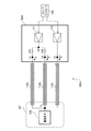
図1は、本発明の第一実施形態に係る電子内視鏡システム1の概略構成を示すブロック図である。図1に示すように、本実施形態の電子内視鏡システム1は、電子内視鏡100、電子内視鏡用プロセッサ200およびモニタ300を備えている。
FIG. 1 is a block diagram showing a schematic configuration of an
電子内視鏡用プロセッサ200は、システムコントローラ202やタイミングコントローラ206を備えている。システムコントローラ202は、メモリ204に記憶された各種プログラムを実行し、電子内視鏡システム1の全体を統合的に制御する。また、システムコントローラ202は、操作パネル208に入力されるユーザ(術者又は補助者)からの指示に応じて、電子内視鏡システム1の各種設定を変更する。タイミングコントローラ206は、各部の動作のタイミングを調整するクロックパルスを電子内視鏡システム1内の各種回路に出力する。
The
また、電子内視鏡用プロセッサ200は、電子内視鏡100のLCB(Light Carrying Bundle)102に白色光束である照明光を供給する光源装置230を備えている。光源装置230は、ランプ232、ランプ電源234、集光レンズ236及び調光装置240を備えている。ランプ232は、ランプ電源234から駆動電力の供給を受けて照明光を放射する高輝度ランプであり、例えば、キセノンランプ、メタルハライドランプ、水銀ランプ又はハロゲンランプが使用される。ランプ232が放射した照明光は、集光レンズ236により集光された後、調光装置240を介してLCB102に導入される。
The
調光装置240は、システムコントローラ202の制御に基づいてLCB102に導入する照明光の光量を調整する装置であり、絞り242、モータ243及びドライバ244を備えている。ドライバ244は、モータ243を駆動するための駆動電流を生成して、モータ243に供給する。絞り242は、モータ243によって駆動され、照明光が通過する開口を変化させて、開口を通過する照明光の光量を調整する。
The dimmer 240 is a device that adjusts the amount of illumination light introduced into the
入射端からLCB102に導入された照明光は、LCB102内を伝播し、電子内視鏡100の先端に配置されたLCB102の出射端から出射して、配光レンズ104を介して被写体に照射される。被写体からの反射光は、対物レンズ106を介して撮像素子108の受光面上で光学像を結ぶ。
Illumination light introduced into the
電源回路150は、ケーブル110を介して、電子内視鏡100の先端部APに配置される撮像素子108などの負荷に電源電圧を供給する。撮像素子108は、例えば各種フィルタが受光面に配置された単板式カラーCCDイメージセンサである。撮像素子108は、スコープコントローラ120からケーブル109を介して送られる制御信号に従って、受光面上で結像した光学像に応じたカラーフィルタ各色の撮像信号を生成する。生成された撮像信号は、スコープコントローラ120においてデジタル画像信号に変換され、電子内視鏡用プロセッサ200の画像処理ユニット220に送られる。また、スコープコントローラ120は、メモリ114(ROMまたは不揮発性メモリ)にアクセスして電子内視鏡100の固有情報を読み出す。メモリ114に記録される電子内視鏡100の固有情報には、例えば撮像素子108の画素数、感度、動作可能なフレームレート等が含まれる。スコープコントローラ120は、メモリ114から読み出した固有情報をシステムコントローラ202に出力する。
The
システムコントローラ202は、電子内視鏡100の固有情報に基づいて各種演算を行い、制御信号を生成する。システムコントローラ202は、生成した制御信号を用いて、電子内視鏡用プロセッサ200に接続された電子内視鏡100に適した処理がなされるように、電子内視鏡用プロセッサ200内の各種回路の動作やタイミングを制御する。タイミングコントローラ206は、システムコントローラ202によるタイミング制御に従って、スコープコントローラ120および画像処理ユニット220にクロックパルスを供給する。
The
電子内視鏡用プロセッサ200の画像処理ユニット220は、システムコントローラ202による制御の下、電子内視鏡100の内視鏡制御部120から送られてくる画像信号に基づいて内視鏡画像等をモニタ表示するためのビデオ信号を生成し、モニタ300に出力する。術者は、モニタ300に表示された内視鏡画像を確認しながら例えば消化管内の観察や治療を行う。
The
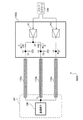
続いて、図2を参照して、本実施形態の電源回路150における電源電圧の制御について説明する。図2は、第一実施形態における電源回路150の構成を示す図である。図2に示すように、本実施形態の電源回路150は、第一電源P1、第二電源P2および第三電源P3を含む。第一電源P1で生成される電源電圧V1は、第一電源線110aを通って撮像素子108に伝送される。また、第二電源P2で生成される電源電圧V2は、第二電源線110bを通って撮像素子108に伝送される。さらに、第三電源P3で生成される電源電圧V3は、第三電源線110cを通って撮像素子108に伝送される。第一電源P1、第二電源P2および第三電源P3は、スコープコントローラ120によってそれぞれ制御される。なお、本実施形態において、電圧値V1と電圧値V2は異なる値とする。
Subsequently, control of the power supply voltage in the
ここで、各電源線110a、110b、110cは長尺ケーブル(例えば数メートル)であるため、撮像素子108に印加される電圧VLには電圧降下が生じる。また、各電源線110a、110b、110cによる損失分は、ケーブルの長さや仕様および先端部APの回路動作における消費電流の変化などによって異なる。そのため、予め設計段階で撮像素子108の消費電流と電源線110aの損失分を仕様値から計算した場合も、正確な電圧VLを得ることは難しい。
Here, since each of the
ここで、第一電源P1の系統に注目すると、撮像素子108にかかる電圧VLは、下記の式(1)で表される。
VL=V1−R1×I1 ・・・ (1)
ここで、R1は第一電源線110aの損失であり、第一電源線110aの単位長あたりの損失をr1、長さをL1とした場合、下記の式(2)で求められる。
R1=r1×L1 ・・・(2)
Here, paying attention to the system of the first power supply P1, the voltage V L applied to the
V L = V 1 −R 1 × I 1 (1)
Here, R 1 is the loss of the first
R 1 = r 1 × L 1 (2)
次に、第二電源P2の系統に注目すると、撮像素子108にかかる電圧VLは、下記の式(3)で表される。
VL=V2−R2×I2 ・・・(3)
ここで、R2は第二電源線110bの損失であり、第二電源線110bの単位長あたりの損失をr2、長さをL2とした場合、下記の式(4)で求められる。
R2=r2×L2 ・・・(4)
Next, paying attention to the system of the second power supply P2, the voltage V L applied to the
V L = V 2 −R 2 × I 2 (3)
Here, R 2 is the loss of the second
R 2 = r 2 × L 2 (4)
そしてr2=n×r1、L2=m×L1とし、式(1)および(3)からVLについて解くと、下記の式(5)が得られる。なお、nは、第一電源線110aと第二電源線110bの「単位長あたりの損失」の比率であり、mは、第一電源線110aと第二電源線110bの「長さ」の比率である。
VL=(n×m×I2×V1−I1× V2)/(n×m×I2−I1)・・・(5)
Then, r 2 = n × r 1 , L 2 = m × L 1, and solving for V L from equations (1) and (3), the following equation (5) is obtained. Here, n is a ratio of “loss per unit length” between the first
V L = (n × m × I 2 × V 1 −I 1 × V 2 ) / (n × m × I 2 −I 1 ) (5)
ここで、本実施形態においては、第一電源線110aおよび第二電源線110bに、同じ長さの同じ仕様の配線材が用いられる。そのため、n=m=1となり、電圧VLは、下記の式(6)で表される。
VL=(I2×V1−I1× V2)/(I2−I1)・・・(6)
Here, in this embodiment, the wiring material of the same specification of the same length is used for the first
V L = (I 2 × V 1 −I 1 × V 2 ) / (I 2 −I 1 ) (6)
したがって、本実施形態では、第一電源線110aにかかる電圧値V1および流れる電流値I1、ならびに第二電源線110bにかかる電圧値V2および流れる電流値I2を求めて、上記の式(6)に当てはめることで、実際に撮像素子108にかかる電圧VLを求めることができる。スコープコントローラ120は、上記式(6)を用いて、撮像素子108にかかる電圧VLを求め、基準電圧Vrefと等しくなるように、第一電源P1および/または第二電源P2を制御して、電圧値V1、電流値I1、電圧値V2、電流値I2のいずれかを調整する。なお、基準電圧Vrefは、撮像素子108の定格電圧である。基準電圧Vrefは、例えば、メモリ114から読み出した電子内視鏡100の固有情報に基づいて設定されても良い。
Therefore, in the present embodiment, the voltage value V 1 and the flowing current value I 1 applied to the first
第一電源P1および/または第二電源P2の制御の一例として、まず、第一電源P1で生成される電圧値V1を固定する。そして、第一電源線110aに流れる電流値I1、および第二電源線110bに流れる電流値I2を電流検出器(不図示)で検出する。スコープコントローラ120は、電圧値V1、電流値I1、電圧値V2、電流値I2を上記式(6)に当てはめて、撮像素子108にかかる電圧VLが撮像素子108の定格電圧Vrefと等しく、または規格範囲に入るように、第二電源P2を制御して電圧値V2を調整する。例えば、上記式(6)より得られた電圧VLが撮像素子108の定格電圧Vrefよりも大きい場合は、電圧値V2を小さくする。そして、再度上記式(6)より電圧VLを求め、定格電圧Vrefと比較する。そして、比較結果に応じて、定格電圧Vrefと等しく、または規格範囲に入るまで、電圧値V2を増減させる。
As an example of control of the first power supply P1 and / or the second power supply P2, first, the voltage value V 1 generated by the first power supply P1 is fixed. Then, the current value I 1 flowing through the first
なお、本実施形態では、第三電源線110cの長さや仕様は任意であり、第三電源P3の出力電圧V3および電流I3は、撮像素子108に供給される電力に応じて適宜設定される。
In the present embodiment, the length and specifications of the third
このように、上記実施形態では、電源電圧を伝送するための電源線を複数設けることで、撮像素子108に実際に印加される電圧VLを電子内視鏡100の基端部側(すなわちスコープコントローラ120)で求めることができる。これにより、電子内視鏡100の種類(ケーブルの長さや仕様)にかかわらず、精度の高い電圧VLを撮像素子108に印加し、撮像素子108を安定して駆動することが可能となる。また、複数の電源線を用いることで、電源線での電圧降下を少なくすることができるため、出力する電源電圧を高く設定する必要がない。
As described above, in the above-described embodiment, by providing a plurality of power supply lines for transmitting the power supply voltage, the voltage VL actually applied to the
また、本実施形態では、撮像素子108と電源回路150とを接続するケーブルをすべて電源線として利用しているため、撮像素子108に印加される電圧VLを検出してフィードバックするための信号線等を別途設ける場合に比べて効率が良く、太径化を防ぎつつ撮像素子108に大きな電力を供給することも可能となる。
In the present embodiment, since all the cables connecting the
続いて、本発明の第二実施形態における電子内視鏡100Aについて説明する。第二実施形態の電子内視鏡100Aは、電源回路150Aの構成のみが第一実施形態と異なり、その他の構成は第一実施形態と同様である。そのため、同様の構成に関する説明については省略する。また、第一実施形態と同様の構成要素については、同じ参照番号を付す。
Next, the
図3は、第二実施形態における電源回路150Aの構成を示す図である。図3に示すように、電源回路150Aは、第一電源P1および第三電源P3を含む。本実施形態では、電源線110aおよび110bが一つの第一電源P1に接続される。第一電源P1によって生成される電圧VPは、電源線110aおよび110bを通って撮像素子108に伝送される。また、第三電源P3によって生成される電圧V3は、電源線110cを介して撮像素子108に伝送される。第一電源P1および第三電源P3は、スコープコントローラ120によってそれぞれ制御される。
FIG. 3 is a diagram showing a configuration of the
第一電源線110aと第一電源P1の間には、第一抵抗PR1が接続される。また、第二電源線110bと第二電源P2の間には第二抵抗PR2が接続される。ここで、PR1およびPR2は、異なる抵抗値を有している(RR1≠RR2)。これにより、第一電源線110aと第二電源線110bに異なる電流が流れる。
A first resistor PR1 is connected between the first
そして、本実施形態においても、撮像素子108にかかる電圧値VLは、上記の式(6)で求めることができる。また、第一電源線110aに流れる電流I1および第二電源線110bに流れる電流I2は、以下の式(7)および(8)でそれぞれ求めることができる。
I1=(VP−V1)/PR1 ・・・(7)
I2=(VP−V2)/PR2 ・・・(8)
Also in this embodiment, the voltage value V L applied to the
I 1 = (V P −V 1 ) / PR1 (7)
I 2 = (V P −V 2 ) / PR2 (8)
すなわち、第一電源線110aの入力点にかかる電圧値V1および第二電源線110bの入力点にかかる電圧値V2を電圧検出器(不図示)によって検出することで、電流I1および電流I2が求まる。スコープコントローラ120は、検出された各電圧値V1およびV2、ならびに式(7)および(8)で計算した電流値I1およびI2を式(6)に当てはめて、撮像素子108にかかる電圧値VLを求める。そして、電圧値VLが基準電圧Vrefと等しく、または規格範囲に入るように、第一電源P1を制御して電圧値VPを調整する。
That is, the voltage value V 1 applied to the input point of the first
このように、第二実施形態においても、第一実施形態と同様に電子内視鏡100の種類にかかわらず、精度の高い電圧VLを撮像素子108に印加することができる。さらに、第一実施形態に比べて電源の個数を減らすことができ、部品点数およびコストの削減、ならびに装置の小型化を実現することが可能となる。
As described above, also in the second embodiment, the voltage V L with high accuracy can be applied to the
続いて、本発明の第三実施形態における電子内視鏡100Bについて説明する。第三実施形態の電子内視鏡100Bは、電源回路150Bの構成のみが第一実施形態と異なり、その他の構成は第一実施形態と同様である。そのため、同様の構成に関する説明については省略する。また、第一実施形態と同様の構成要素については、同じ参照番号を付す。
Next, the
図4は、第三実施形態における電源回路150Bの構成を示す図である。図4に示すように、電源回路150Bは、第二実施形態の電源回路150Aと同様に、第一電源P1および第三電源P3を含み、第一電源線110aおよび第二電源線110bが第一電源P1に接続される。また、第一電源線110aおよび第二電源線110bと第一電源P1との間には、第一抵抗PR1および第二抵抗PR2(RR1≠RR2)がそれぞれ接続される。
FIG. 4 is a diagram showing a configuration of the
さらに、本実施形態では、第一電源線110aと第一抵抗PR1との接続点に、第一コンデンサC1が設けられる。また、第二電源線110bと第二抵抗PR2との接続点には、第二コンデンサC2が設けられる。第一コンデンサC1および第二コンデンサC2は、グランドに接地されたバイパスコンデンサであり、第一電源線110aおよび第二電源線110bに発生する外乱ノイズを除去するためのものである。
Further, in the present embodiment, a first capacitor C1 is provided at a connection point between the first
そして、本実施形態では、第二実施形態と同様に、スコープコントローラ120は、第一電源線110aの入力点にかかる電圧値V1および第二電源線110bの入力点にかかる電圧値V2を電圧検出器(不図示)によって検出し、式(7)および(8)から電流値I1およびI2を計算する。そして、これらを式(6)に当てはめて、撮像素子108にかかる電圧値VLを求め、電圧値VLが基準電圧Vrefと等しく、または規格範囲に入るように、第一電源P1を制御して電圧値VPを調整する。
In this embodiment, as in the second embodiment, the
このように、第三実施形態においても、第一および第二実施形態と同様の効果を得ることができる。さらに、第一コンデンサC1および第二コンデンサC2を設けることで、ノイズを除去し、より正確な電圧値V1およびV2の検出を行うことができる。その結果、より精度の高い電圧VLを撮像素子108に印加することが可能となる。
Thus, also in 3rd embodiment, the effect similar to 1st and 2nd embodiment can be acquired. Further, by providing the first capacitor C1 and the second capacitor C2, noise can be removed and more accurate voltage values V 1 and V 2 can be detected. As a result, it becomes possible to apply the voltage V L with higher accuracy to the
続いて、本発明の第四実施形態における電子内視鏡100Cについて説明する。第四実施形態の電子内視鏡100Cは、電源回路150Cの構成のみが第一実施形態と異なり、その他の構成は第一実施形態と同様である。そのため、同様の構成に関する説明については省略する。また、第一実施形態と同様の構成要素については、同じ参照番号を付す。
Next, an
図5は、第四実施形態における電源回路150Cの構成を示す図である。図5に示すように、本実施形態の電源回路150Cは第一電源P1を含む。第一電源P1によって生成される電圧VPは、第一電源線110a、第二電源線110bおよび第三電源線110cを通って撮像素子108に伝送される。
FIG. 5 is a diagram showing a configuration of a
また、第一電源線110aおよび第二電源線110bと第一電源P1との間には、第一抵抗PR1および第二抵抗PR2(RR1≠RR2)がそれぞれ接続される。さらに、第三電源線110cおよび第一電源P1との間にも、第三抵抗PR3が接続される。尚、第三抵抗PR3の値は撮像素子108に供給される電力に応じて適宜設定される。
A first resistor PR1 and a second resistor PR2 (RR1 ≠ RR2) are connected between the first
そして、本実施形態においても、第二実施形態と同様に、スコープコントローラ120は、第一電源線110aの入力点にかかる電圧値V1および第二電源線110bの入力点にかかる電圧値V2を電圧検出器(不図示)によって検出し、式(7)および(8)から電流値I1およびI2を計算する。そして、これらを式(6)に当てはめて、撮像素子108にかかる電圧値VLを求め、電圧値VLが基準電圧Vrefと等しく、または規格範囲に入るように、第一電源P1を制御して電圧値VPを調整する。
Also in the present embodiment, as in the second embodiment, the
このように、第四実施形態においても、第一および第二実施形態と同様の効果を得ることができるとともに、電源の個数をさらに減らすことができ、部品点数およびコストのさらなる削減、ならびに装置のさらなる小型化を実現することが可能となる。尚、ノイズ対策のために、本実施形態においても、第三実施形態と同様に、各電源線と抵抗との接続点にバイパスコンデンサを設ける構成としても良い。 Thus, in the fourth embodiment, the same effects as those of the first and second embodiments can be obtained, the number of power supplies can be further reduced, the number of parts and cost can be further reduced, and the apparatus Further downsizing can be realized. As a countermeasure against noise, the present embodiment may be configured such that a bypass capacitor is provided at a connection point between each power supply line and a resistor as in the third embodiment.
以上が本発明の実施形態の説明であるが、本発明は、上記の構成に限定されるものではなく、本発明の技術的思想の範囲において様々な実施形態の組み合わせや変形が可能である。例えば、撮像素子として、CCD以外のイメージセンサ(CMOSなど)を用いることも可能である。また、電子内視鏡100の先端部APには、撮像素子108などの撮像素子だけでなく、それ以外の機能(例えばレンズ駆動機能など)を有する回路等を設けることも可能である。この場合も、電源回路150は、先端部APに配置される負荷全体に対して供給される電源電圧を上記の方法で制御する。
The above is the description of the embodiments of the present invention, but the present invention is not limited to the above-described configuration, and various combinations and modifications of the embodiments are possible within the scope of the technical idea of the present invention. For example, an image sensor (such as a CMOS) other than a CCD can be used as the image sensor. In addition, the distal end AP of the
また、電子内視鏡用プロセッサ200に電源回路150を備え、スコープコントローラ120の代わりにシステムコントローラ202によって、電源回路150を制御する構成としても良い。また、本発明の電子内視鏡100は、医療用に限定されるものではなく、工業用の内視鏡であっても良い。さらに、本発明は、内視鏡にも限定されず、長尺のケーブルを介して負荷に電源電圧を供給する電源回路を備える様々な装置に適用可能である。
Further, the
また、上記実施形態においては、第一電源線110aおよび第二電源線110bは、いずれも同じ長さおよび同じ仕様(損失)のケーブルが用いられることとしたが、これに限定されるものではない。第一電源線110aと第二電源線110bの「単位長あたりの損失」の比率(n)、および「長さ」の比率(m)がわかっていれば、上記の式(5)から撮像素子108に印加される電圧VLを求めることができる。なお、この場合も「単位長あたりの損失」および「長さ」の比率がわかっていればよく、それぞれの具体的な値は必要としない。
In the above-described embodiment, the first
さらに、上記実施形態においては、三本の電源線で撮像素子108に電力を供給する構成について説明したが、これに限定されるものではなく、少なくとも二本の電源線であればよく、四本以上であっても良い。四本以上の場合も、二本の電源線にかかる電圧値および流れる電流値から撮像素子108に印加される電圧VLを求めることができる。
Furthermore, in the above-described embodiment, the configuration in which power is supplied to the
1 電子内視鏡システム
100 電子内視鏡
108 撮像素子
110a、110b、110c 電源線
114 メモリ
120 スコープコントローラ
150 電源回路
P1、P2、P3 電源
PR1、PR2 抵抗
C1、C2 コンデンサ
200 電子内視鏡用プロセッサ
202 システムコントローラ
206 タイミングコントローラ
220 画像処理ユニット
300 モニタ
DESCRIPTION OF
Claims (10)
前記ケーブルは、
電源電圧を前記負荷に伝送するための第一電源線および第二電源線を備え、
前記電源回路は、
前記電源電圧を生成し、前記第一電源線および第二電源線に出力する電源手段であって、少なくとも一つの電源からなる電源手段を備え、
前記制御手段は、
前記第一電源線の入力点にかかる電圧、前記第一電源線に流れる電流、前記第二電源線の入力点にかかる電圧および前記第二電源線に流れる電流に基づいて、前記負荷に印加される電圧を求め、
前記負荷に印加される電圧が所定の基準電圧と略等しくなるように、前記電源手段を制御して、前記生成する電源電圧を調整することを特徴とする負荷電圧制御装置。 A load voltage control device comprising: a load disposed at a distal end; a power supply circuit and control means disposed at a proximal end; and a long cable connecting the distal end and the proximal end. ,
The cable is
A first power supply line and a second power supply line for transmitting a power supply voltage to the load;
The power supply circuit is
A power supply means for generating the power supply voltage and outputting it to the first power supply line and the second power supply line, comprising power supply means comprising at least one power supply,
The control means includes
Applied to the load based on the voltage applied to the input point of the first power supply line, the current flowing through the first power supply line, the voltage applied to the input point of the second power supply line, and the current flowing through the second power supply line. Voltage
A load voltage control apparatus, wherein the power supply means is controlled to adjust the generated power supply voltage so that a voltage applied to the load is substantially equal to a predetermined reference voltage.
前記第一電源線は、前記第一電源に接続され、
前記第二電源線は、前記第二電源に接続される、ことを特徴とする、請求項1に記載の負荷電圧制御装置。 The power source means comprises a first power source and a second power source,
The first power supply line is connected to the first power supply,
The load voltage control device according to claim 1, wherein the second power supply line is connected to the second power supply.
前記電源回路は、さらに、
前記第一電源線と前記一つの電源との間に接続される第一抵抗と、
前記第二電源線と前記一つの電源との間に接続される第二抵抗であって、前記第一抵抗とは異なる第二抵抗と、を備えることを特徴とする、請求項1に記載の負荷電圧制御装置。 The power source means comprises one power source,
The power supply circuit further includes:
A first resistor connected between the first power supply line and the one power supply;
The second resistor connected between the second power supply line and the one power supply, the second resistor being different from the first resistor, according to claim 1, Load voltage control device.
前記第一電源線と前記第一抵抗との接続点に設けられた第一コンデンサと、
前記第二電源線と前記第二抵抗との接続点に設けられた第二コンデンサと、を備えることを特徴とする、請求項3に記載の負荷電圧制御装置。 The power supply circuit further includes:
A first capacitor provided at a connection point between the first power line and the first resistor;
The load voltage control apparatus according to claim 3, further comprising: a second capacitor provided at a connection point between the second power supply line and the second resistor.
VL=(I2×V1−I1× V2)/(I2−I1)
V1は前記第一電源線の入力点にかかる電圧、I1は前記第一電源線に流れる電流、V2は前記第二電源線の入力点にかかる電圧、I2は前記第二電源線に流れる電流であることを特徴とする、請求項5に記載の負荷電圧制御装置。 The control means obtains the voltage VL applied to the load based on the following equation:
V L = (I 2 × V 1 −I 1 × V 2 ) / (I 2 −I 1 )
V 1 is a voltage applied to the input point of the first power line, I 1 is a current flowing through the first power line, V 2 is a voltage applied to the input point of the second power line, and I 2 is the second power line. The load voltage control device according to claim 5, wherein the load voltage control device is a current flowing through the load.
VL=(n×m×I2×V1−I1× V2)/(n×m×I2−I1)
V1は前記第一電源線の入力点にかかる電圧、I1は前記第一電源線に流れる電流、V2は前記第二電源線の入力点にかかる電圧、I2は前記第二電源線に流れる電流、nは前記第一電源線と前記第二電源線の単位長あたりの損失の比率、mは前記第一電源線と前記第二電源線の長さの比率である、請求項1から4のいずれか一項に記載の負荷電圧制御装置。 The control means obtains the voltage VL applied to the load based on the following equation:
V L = (n × m × I 2 × V 1 −I 1 × V 2 ) / (n × m × I 2 −I 1 )
V 1 is a voltage applied to the input point of the first power line, I 1 is a current flowing through the first power line, V 2 is a voltage applied to the input point of the second power line, and I 2 is the second power line. 2, n is a ratio of loss per unit length of the first power supply line and the second power supply line, and m is a ratio of the length of the first power supply line and the second power supply line. To 4. The load voltage control device according to any one of claims 1 to 4.
前記ケーブルは、電源電圧を前記負荷に伝送するための第一電源線および第二電源線を備え、
前記電源回路は、前記電源電圧を生成し、前記第一電源線および第二電源線に出力する電源手段であって、少なくとも一つの電源からなる電源手段を備え、
前記制御手段は、
前記第一電源線の入力点にかかる電圧、前記第一電源線に流れる電流、前記第二電源線の入力点にかかる電圧および前記第二電源線に流れる電流に基づいて、前記負荷に印加される電圧を求め、
前記負荷に印加される電圧が所定の基準電圧と略等しくなるように、前記電源手段を制御して、前記生成する電源電圧を調整することを特徴とする電子内視鏡。 An electronic internal circuit comprising: a load including at least an image sensor disposed at the distal end; a power supply circuit and control means disposed at the proximal end; and a long cable connecting the distal end and the proximal end. A endoscope,
The cable includes a first power supply line and a second power supply line for transmitting a power supply voltage to the load,
The power supply circuit is a power supply means that generates the power supply voltage and outputs the power supply voltage to the first power supply line and the second power supply line, and includes power supply means including at least one power supply,
The control means includes
Applied to the load based on the voltage applied to the input point of the first power supply line, the current flowing through the first power supply line, the voltage applied to the input point of the second power supply line, and the current flowing through the second power supply line. Voltage
An electronic endoscope characterized by adjusting the power supply voltage to be generated by controlling the power supply means so that a voltage applied to the load is substantially equal to a predetermined reference voltage.
前記ケーブルは、電源電圧を前記負荷に伝送するための第一電源線および第二電源線を備え、
前記電源回路は、前記電源電圧を生成し、前記第一電源線および第二電源線に出力する電源手段であって、少なくとも一つの電源からなる電源手段を備え、
前記制御手段は、
前記第一電源線の入力点にかかる電圧、前記第一電源線に流れる電流、前記第二電源線の入力点にかかる電圧および前記第二電源線に流れる電流に基づいて、前記負荷に印加される電圧を求め、
前記負荷に印加される電圧が所定の基準電圧と略等しくなるように、前記電源手段を制御して、前記生成する電源電圧を調整することを特徴とする電子内視鏡システム。
An electronic endoscope connected to the processor, comprising a power supply circuit and a control means, a load including at least an image sensor, and a long cable connecting the load and the power supply circuit An electronic endoscope system comprising an endoscope,
The cable includes a first power supply line and a second power supply line for transmitting a power supply voltage to the load,
The power supply circuit is a power supply means that generates the power supply voltage and outputs the power supply voltage to the first power supply line and the second power supply line, and includes power supply means including at least one power supply,
The control means includes
Applied to the load based on the voltage applied to the input point of the first power supply line, the current flowing through the first power supply line, the voltage applied to the input point of the second power supply line, and the current flowing through the second power supply line. Voltage
An electronic endoscope system, wherein the power supply means is controlled to adjust the generated power supply voltage so that a voltage applied to the load is substantially equal to a predetermined reference voltage.
Priority Applications (5)
| Application Number | Priority Date | Filing Date | Title |
|---|---|---|---|
| JP2014071142A JP6258751B2 (en) | 2014-03-31 | 2014-03-31 | Load voltage control device, electronic endoscope and electronic endoscope system |
| US14/645,797 US9627960B2 (en) | 2014-03-31 | 2015-03-12 | Load voltage control device, electronic endoscope and electronic endoscope system |
| CN201510134011.3A CN104950966B (en) | 2014-03-31 | 2015-03-25 | Load voltage control device, fujinon electronic video endoscope and electronic endoscope system |
| DE102015104971.6A DE102015104971B4 (en) | 2014-03-31 | 2015-03-31 | Load voltage control device, electronic endoscope and electronic endoscope system |
| US15/455,288 US9979204B2 (en) | 2014-03-31 | 2017-03-10 | Load voltage control device, electronic endoscope and electronic endoscope system |
Applications Claiming Priority (1)
| Application Number | Priority Date | Filing Date | Title |
|---|---|---|---|
| JP2014071142A JP6258751B2 (en) | 2014-03-31 | 2014-03-31 | Load voltage control device, electronic endoscope and electronic endoscope system |
Publications (2)
| Publication Number | Publication Date |
|---|---|
| JP2015192696A JP2015192696A (en) | 2015-11-05 |
| JP6258751B2 true JP6258751B2 (en) | 2018-01-10 |
Family
ID=54067089
Family Applications (1)
| Application Number | Title | Priority Date | Filing Date |
|---|---|---|---|
| JP2014071142A Active JP6258751B2 (en) | 2014-03-31 | 2014-03-31 | Load voltage control device, electronic endoscope and electronic endoscope system |
Country Status (4)
| Country | Link |
|---|---|
| US (2) | US9627960B2 (en) |
| JP (1) | JP6258751B2 (en) |
| CN (1) | CN104950966B (en) |
| DE (1) | DE102015104971B4 (en) |
Families Citing this family (9)
| Publication number | Priority date | Publication date | Assignee | Title |
|---|---|---|---|---|
| EP2954834A4 (en) * | 2013-08-09 | 2016-11-30 | Olympus Corp | Endoscopic device |
| JP6165356B2 (en) * | 2015-06-26 | 2017-07-19 | オリンパス株式会社 | Endoscope system |
| JP6787635B2 (en) * | 2017-01-12 | 2020-11-18 | オリンパス株式会社 | Endoscope device |
| WO2018193519A1 (en) * | 2017-04-18 | 2018-10-25 | オリンパス株式会社 | Endoscope device and video processor |
| CN110300247B (en) * | 2019-07-03 | 2021-07-09 | 豪威科技(上海)有限公司 | Endoscope control circuit and endoscope |
| WO2021171427A1 (en) * | 2020-02-26 | 2021-09-02 | オリンパス株式会社 | Control device, endoscope, and control method |
| WO2022064667A1 (en) * | 2020-09-28 | 2022-03-31 | オリンパスメディカルシステムズ株式会社 | Image-capturing device and endoscopic system |
| WO2023002571A1 (en) * | 2021-07-20 | 2023-01-26 | オリンパスメディカルシステムズ株式会社 | Imaging device, endoscope system, control unit, camera unit, scope, and imaging method |
| CN114224268B (en) * | 2022-02-24 | 2022-05-03 | 极限人工智能有限公司 | Image processing device and endoscopic video system |
Family Cites Families (18)
| Publication number | Priority date | Publication date | Assignee | Title |
|---|---|---|---|---|
| JPS6059410A (en) * | 1983-09-12 | 1985-04-05 | Nippon Telegr & Teleph Corp <Ntt> | Decentralized power supply device for large electronic device |
| JPH0828839B2 (en) | 1987-04-21 | 1996-03-21 | オリンパス光学工業株式会社 | TV camera device |
| JP2003038434A (en) * | 2001-07-27 | 2003-02-12 | Pentax Corp | Electronic endoscope device |
| JP4648717B2 (en) * | 2005-02-04 | 2011-03-09 | Hoya株式会社 | CCD damage prevention system |
| JP2006217317A (en) * | 2005-02-04 | 2006-08-17 | Pentax Corp | Damage prevention system for charge coupled device |
| US20060223637A1 (en) * | 2005-03-31 | 2006-10-05 | Outland Research, Llc | Video game system combining gaming simulation with remote robot control and remote robot feedback |
| JP4789662B2 (en) * | 2006-03-17 | 2011-10-12 | 富士通セミコンダクター株式会社 | Power supply device control circuit, power supply device and control method therefor |
| JP2007252738A (en) * | 2006-03-24 | 2007-10-04 | Fujinon Corp | Endoscopic apparatus |
| JP4814717B2 (en) * | 2006-07-28 | 2011-11-16 | Hoya株式会社 | Electronic endoscope and electronic endoscope system |
| JP5185520B2 (en) * | 2006-09-22 | 2013-04-17 | オリンパス株式会社 | Electronic endoscope device |
| JP2009106442A (en) * | 2007-10-29 | 2009-05-21 | Olympus Medical Systems Corp | Imaging system |
| JP2009189529A (en) * | 2008-02-14 | 2009-08-27 | Fujinon Corp | Processor unit for endoscope |
| JP5272053B2 (en) * | 2011-07-26 | 2013-08-28 | 富士フイルム株式会社 | Electronic endoscope apparatus and electronic endoscope system |
| JP2013044807A (en) * | 2011-08-22 | 2013-03-04 | Olympus Corp | Endoscopic device |
| JP5588949B2 (en) * | 2011-09-30 | 2014-09-10 | 富士フイルム株式会社 | Endoscope system and endoscope external control device |
| CN102571014B (en) * | 2012-02-10 | 2014-03-12 | 中国科学院微电子研究所 | Voltage type automatic gain control circuit |
| JP5865210B2 (en) * | 2012-08-13 | 2016-02-17 | オリンパス株式会社 | Imaging system |
| GB201315680D0 (en) * | 2013-09-03 | 2013-10-16 | Cooper Technologies Co | Network power supply |
-
2014
- 2014-03-31 JP JP2014071142A patent/JP6258751B2/en active Active
-
2015
- 2015-03-12 US US14/645,797 patent/US9627960B2/en active Active
- 2015-03-25 CN CN201510134011.3A patent/CN104950966B/en active Active
- 2015-03-31 DE DE102015104971.6A patent/DE102015104971B4/en active Active
-
2017
- 2017-03-10 US US15/455,288 patent/US9979204B2/en active Active
Also Published As
| Publication number | Publication date |
|---|---|
| DE102015104971B4 (en) | 2020-08-13 |
| US9979204B2 (en) | 2018-05-22 |
| US20170187195A1 (en) | 2017-06-29 |
| DE102015104971A1 (en) | 2015-10-01 |
| US9627960B2 (en) | 2017-04-18 |
| JP2015192696A (en) | 2015-11-05 |
| CN104950966A (en) | 2015-09-30 |
| CN104950966B (en) | 2018-07-17 |
| US20150280550A1 (en) | 2015-10-01 |
Similar Documents
| Publication | Publication Date | Title |
|---|---|---|
| JP6258751B2 (en) | Load voltage control device, electronic endoscope and electronic endoscope system | |
| JP5789348B2 (en) | Light source device | |
| JP6045760B2 (en) | Imaging system | |
| JP6072374B2 (en) | Observation device | |
| JP2011206333A (en) | Power supply device of cmos image sensor in endoscope apparatus | |
| JP2007037565A (en) | Endoscope system | |
| US9766447B2 (en) | Light source apparatus | |
| JP6265815B2 (en) | Electronic endoscope system | |
| JP2012085720A (en) | Endoscopic device | |
| JPWO2014156253A1 (en) | Endoscope device | |
| JP5855795B2 (en) | Endoscope device | |
| JP6082658B2 (en) | Imaging device and endoscope apparatus | |
| JP2011083454A (en) | Electronic endoscope | |
| CN110300247B (en) | Endoscope control circuit and endoscope | |
| US20170086662A1 (en) | Scanning endoscope apparatus | |
| WO2017212650A1 (en) | Endoscope and endoscope device | |
| JP6172738B2 (en) | Electronic endoscope and electronic endoscope system | |
| EP3090680B1 (en) | Systems for regulating temperature and illumination intensity at the distal tip of an endoscope | |
| JP2009095466A (en) | Endoscope system | |
| JP2018000498A (en) | Endoscope system | |
| JP6062133B1 (en) | Endoscope system | |
| JP6741412B2 (en) | Signal transmission device and electronic endoscope system | |
| JP6207226B2 (en) | Endoscope system | |
| JP2005230258A (en) | Water leakage judging apparatus for endoscope | |
| JP2015181586A (en) | Endoscope apparatus, camera head, and control apparatus |
Legal Events
| Date | Code | Title | Description |
|---|---|---|---|
| A621 | Written request for application examination |
Free format text: JAPANESE INTERMEDIATE CODE: A621 Effective date: 20161219 |
|
| RD04 | Notification of resignation of power of attorney |
Free format text: JAPANESE INTERMEDIATE CODE: A7424 Effective date: 20170717 |
|
| A131 | Notification of reasons for refusal |
Free format text: JAPANESE INTERMEDIATE CODE: A131 Effective date: 20170817 |
|
| A977 | Report on retrieval |
Free format text: JAPANESE INTERMEDIATE CODE: A971007 Effective date: 20170816 |
|
| TRDD | Decision of grant or rejection written | ||
| A01 | Written decision to grant a patent or to grant a registration (utility model) |
Free format text: JAPANESE INTERMEDIATE CODE: A01 Effective date: 20171115 |
|
| A61 | First payment of annual fees (during grant procedure) |
Free format text: JAPANESE INTERMEDIATE CODE: A61 Effective date: 20171207 |
|
| R150 | Certificate of patent or registration of utility model |
Ref document number: 6258751 Country of ref document: JP Free format text: JAPANESE INTERMEDIATE CODE: R150 |
|
| R250 | Receipt of annual fees |
Free format text: JAPANESE INTERMEDIATE CODE: R250 |
|
| R250 | Receipt of annual fees |
Free format text: JAPANESE INTERMEDIATE CODE: R250 |
|
| R250 | Receipt of annual fees |
Free format text: JAPANESE INTERMEDIATE CODE: R250 |
|
| R250 | Receipt of annual fees |
Free format text: JAPANESE INTERMEDIATE CODE: R250 |