JP6257198B2 - Optical apparatus, control method therefor, and control program - Google Patents
Optical apparatus, control method therefor, and control program Download PDFInfo
- Publication number
- JP6257198B2 JP6257198B2 JP2013151477A JP2013151477A JP6257198B2 JP 6257198 B2 JP6257198 B2 JP 6257198B2 JP 2013151477 A JP2013151477 A JP 2013151477A JP 2013151477 A JP2013151477 A JP 2013151477A JP 6257198 B2 JP6257198 B2 JP 6257198B2
- Authority
- JP
- Japan
- Prior art keywords
- mode
- image
- focus detection
- detection
- region
- Prior art date
- Legal status (The legal status is an assumption and is not a legal conclusion. Google has not performed a legal analysis and makes no representation as to the accuracy of the status listed.)
- Active
Links
Images


Landscapes
- Exposure Control For Cameras (AREA)
- Focusing (AREA)
- Details Of Cameras Including Film Mechanisms (AREA)
- Automatic Focus Adjustment (AREA)
- Studio Devices (AREA)
Description
本発明は、光学機器、その制御方法、および制御プログラムに関し、特に、焦点調節のための測距点入力部を複数備える光学機器に関する。 The present invention relates to an optical device, a control method thereof, and a control program, and more particularly, to an optical device including a plurality of distance measuring point input units for focus adjustment.
一般に、デジタルカメラなどの光学機器において、ファインダー観察者の視線情報と被写体情報とに応じて、測距点(焦点検出領域)を選択するようにした光学機器が知られている。そして、被写体に係る情報を検知する被写体検知機能を有する光学機器として、種々の光学機器がある(例えば、特許文献1参照)。 In general, in an optical apparatus such as a digital camera, an optical apparatus that selects a distance measuring point (focus detection region) according to the line-of-sight information and subject information of a finder observer is known. Various optical devices are available as optical devices having a subject detection function for detecting information related to a subject (see, for example, Patent Document 1).
特許文献1に記載の光学機器では、撮像部で得られた画像データに含まれる人物(被写体)の眼を検出して、当該検出結果に応じて焦点を合わせる被写体の位置および大きさを示すフォーカス枠を設定して、撮影の際の合焦点位置を決定するようにしている。 In the optical device described in Patent Document 1, a focus indicating the position and size of a subject to be detected by detecting the eyes of a person (subject) included in the image data obtained by the imaging unit and focusing according to the detection result. A frame is set to determine the focal position at the time of shooting.
さらに、ファインダー観察者の視線を検知する視線検知機能を有する光学機器として、種々の光学機器が知られている(例えば、特許文献2参照)。 Furthermore, various optical devices are known as optical devices having a line-of-sight detection function for detecting the line of sight of a viewfinder observer (see, for example, Patent Document 2).
特許文献2に記載の光学機器では、測距点を選択する際のモードとして、自動設定モード、視線検知モード、およびマニュアル設定モードが備えられ、これらモードの選択について、測距点選択の切り換えによって行うようにしている。そして、視線検知モードによる測距点の設定が行われている際、マニュアル設定モードが選択されると、当該マニュアル設定モードが優先されて、撮影者(ユーザ)の意図を反映するようにしている。
The optical apparatus described in
加えて、デジタルカメラなどの光学機器において、被写体像を表示する表示装置にタッチパネルを搭載して、測距点をタッチ操作によって選択するようにしたものがある。 In addition, there is an optical device such as a digital camera in which a touch panel is mounted on a display device that displays a subject image, and a ranging point is selected by a touch operation.
ところが、上述のような被写体検知機能によって測距点を選択する際、被写体の大きさ、色、および明るさなどによって測距点を誤検知することがある。一方、視線検知機能による視線の検知においても、観察者(つまり、ユーザ)個々の眼球および左右いずれの眼で観察するかなどによって視線の検知に差が生じる。このような差をキャリブレーションなどによって校正したとしても、撮影者の意図通りに測距点を選択することが困難となることがある。 However, when a distance measuring point is selected by the subject detection function as described above, the distance measuring point may be erroneously detected depending on the size, color, and brightness of the subject. On the other hand, in the detection of the line of sight by the line-of-sight detection function, there is a difference in the detection of the line of sight depending on whether the observer (that is, the user) observes with each eyeball or left or right eye. Even if such a difference is calibrated by calibration or the like, it may be difficult to select a distance measuring point as intended by the photographer.
加えて、従来の光学機器においては、被写体検知機能および視線検知機能の双方を用いて測距点を設定することは行われていない。そして、被写体検知機能および視線検知機能を用いて測距点を選択した後、ユーザによって測距点の変更が行われた際にどのようにして測距点を決定するかについても記載されていない。 In addition, in the conventional optical apparatus, the ranging point is not set by using both the subject detection function and the line-of-sight detection function. Also, there is no description on how to determine the distance measurement point when the user changes the distance measurement point after selecting the distance measurement point using the subject detection function and the gaze detection function. .
さらに、一眼レフカメラなどの光学機器において、ファインダーを覗きながら撮影を行う場合に、表示装置にタッチパネルが搭載されていたとしても、ユーザは測距点の選択のためにファインダーから表示装置に視線を移さなければならず、タッチ操作によって測距点の選択を行うことは困難である。 In addition, in an optical device such as a single-lens reflex camera, when taking a picture while looking through the viewfinder, even if the display device is equipped with a touch panel, the user looks at the display device from the viewfinder to select a distance measuring point. It is difficult to select a distance measuring point by a touch operation.
そこで、本発明の目的は、焦点調節のための測距点入力部を複数備える光学機器において、測距点の選択を撮影者の意図を反映させつつ行うことのできる光学機器、その制御方法、および制御プログラムを提供することにある。 Accordingly, an object of the present invention is to provide an optical apparatus capable of performing selection of a distance measurement point while reflecting the intention of the photographer in an optical apparatus including a plurality of distance measurement point input units for focus adjustment, a control method thereof, And providing a control program.
上記の目的を達成するため、本発明による光学機器は、画像から特定の被写体の領域を検出する第1の検出手段と、撮影者の眼をモニターして前記画像おいて目視されている位置を検出する第2の検出手段と、複数の撮影モードから撮影モードを選択するモード選択手段と、前記第1の検出手段によって検出された前記特定の被写体の領域に基づく第1の範囲に、前記第2の検出手段によって検出された画像において目視されている位置が含まれている場合に、前記特定の被写体の領域に基づいて複数の焦点検出領域から焦点検出領域を選択し、前記第1の範囲に、前記第2の検出手段によって検出された画像において目視されている位置が含まれていない場合に、前記画像において目視されている位置に基づいて複数の焦点検出領域から焦点検出領域を選択する領域選択手段と、有し、前記第1の範囲は、前記モード選択手段によって選択された前記撮影モードに応じて設定されることを特徴とする。 In order to achieve the above object, an optical apparatus according to the present invention includes a first detection unit that detects a region of a specific subject from an image, and a position that is viewed in the image by monitoring a photographer's eyes. A second detection means for detecting; a mode selection means for selecting a shooting mode from a plurality of shooting modes; and a first range based on the area of the specific subject detected by the first detection means. A focus detection region is selected from a plurality of focus detection regions based on the region of the specific subject when the position being viewed in the image detected by the second detection unit is included; to, if it does not contain a position that is visible in the image detected by said second detection means, focus from a plurality of focus detection areas on the basis of the position that is visible in the image Area selecting means for selecting the detection area has, the first range, characterized in that it is set in accordance with the photographing mode selected by said mode selecting means.
本発明による光学機器の制御方法は、画像から特定の被写体の領域を検出する第1の検出ステップと、撮影者の眼をモニターして前記画像おいて目視されている位置を検出する第2の検出ステップと、複数の撮影モードから撮影モードを選択するモード選択ステップと、前記第1の検出ステップで検出された前記特定の被写体の領域に基づく第1の範囲に、前記第2の検出ステップで検出された画像において目視されている位置が含まれている場合に、前記特定の被写体の領域に基づいて複数の焦点検出領域から焦点検出領域を選択し、前記第1の範囲に、前記第2の検出ステップで検出された画像において目視されている位置が含まれていない場合に、前記画像において目視されている位置に基づいて複数の焦点検出領域から焦点検出領域を選択する領域選択ステップと、有し、前記第1の範囲は、前記モード選択ステップで選択された前記撮影モードに応じて設定されることを特徴とすることを特徴とする。 The method for controlling an optical apparatus according to the present invention includes a first detection step for detecting a region of a specific subject from an image, and a second detection for detecting a position viewed by the photographer's eyes and monitoring the image. A detection step, a mode selection step of selecting a shooting mode from a plurality of shooting modes, and a first range based on the region of the specific subject detected in the first detection step, in the second detection step. When the position being viewed in the detected image is included, a focus detection area is selected from a plurality of focus detection areas based on the area of the specific subject, and the second range falls within the first range. focus detection area from a plurality of focus detection areas on the basis of the case does not include a position which is visible in the image detected by the detection step, a position which is visible in the image A region selection step of selecting includes the first range is characterized in that characterized in that it is set in response to said mode selection the photographing mode selected in step.
本発明による制御プログラムは、光学機器で用いられる制御プログラムであって、前記光学機器が備えるコンピュータに、画像から特定の被写体の領域を検出する第1の検出ステップと、撮影者の眼をモニターして前記画像おいて目視されている位置を検出する第2の検出ステップと、複数の撮影モードから撮影モードを選択するモード選択ステップと、前記第1の検出ステップで検出された前記特定の被写体の領域に基づく第1の範囲に、前記第2の検出ステップで検出された画像において目視されている位置が含まれている場合に、前記特定の被写体の領域に基づいて複数の焦点検出領域から焦点検出領域を選択し、前記第1の範囲に、前記第2の検出ステップで検出された画像において目視されている位置が含まれていない場合に、前記画像において目視されている位置に基づいて複数の焦点検出領域から焦点検出領域を選択する領域選択ステップと、実行させ、前記第1の範囲は、前記モード選択ステップで選択された前記撮影モードに応じて設定されることを特徴とすることを特徴とする。 A control program according to the present invention is a control program used in an optical device, and monitors a photographer's eyes in a first detection step of detecting a region of a specific subject from an image on a computer provided in the optical device. A second detection step for detecting a position viewed in the image, a mode selection step for selecting a shooting mode from a plurality of shooting modes, and the specific object detected in the first detection step. When the first range based on the region includes a position that is visually observed in the image detected in the second detection step, the focus from a plurality of focus detection regions is based on the region of the specific subject. When a detection area is selected and the first range does not include a position that is viewed in the image detected in the second detection step, An area selecting step of selecting a focus detection area from a plurality of focus detection areas on the basis of the position that is visible in the image, is executed, the first range, depending on the photographing mode selected by said mode selecting step It is characterized by being set .
本発明によれば、撮影者の意図に応じた焦点検出領域が選択されるようになって、焦点検出領域を選択する際の利便性を向上させることができる。 According to the present invention, the focus detection area corresponding to the intention of the shadow's shooting is adapted to be selected, it is possible to improve the convenience when selecting a focus detection area.
以下、本発明の実施の形態による光学機器の一例について図面を参照して説明する。 Hereinafter, an example of an optical apparatus according to an embodiment of the present invention will be described with reference to the drawings.
図1は、本発明の実施の形態による光学機器の一例についてその外観を示す図である。そして、図1(a)は背面側から示す図であり、図1(b)は正面側から示す図である。 FIG. 1 is a diagram showing an appearance of an example of an optical apparatus according to an embodiment of the present invention. FIG. 1A is a view shown from the back side, and FIG. 1B is a view shown from the front side.
図示の光学機器は、所謂レンズ交換式の一眼レフカメラ(以下単にカメラと呼ぶ)であり、カメラはカメラ本体100を有している。撮影を開始する際には、ユーザは、撮影条件などの設定を行うため、撮影メニューを表示するメニュー釦106を押す。そして、ユーザはダイアル103を用いて各種設定変更を行う。
The illustrated optical apparatus is a so-called interchangeable lens type single-lens reflex camera (hereinafter simply referred to as a camera), and the camera has a
接眼光学系109を備えるファインダーの上下にはそれぞれ視線検知部110aおよび110bが配置されている。被写体像を確認するため、ユーザ(撮影者ともいう)がファインダーを覗くと、視線検知部110aおよび110bによって撮影者の視線が検知され、撮影者がファインダーを通して被写体のいずれの箇所を目視しているかが判定される。
Line-of-
測距スタート釦101を押すと測距動作が行われるが、測距点選択部(マルチコントローラ:以下MCという)102によって撮影者は測距点(焦点検出領域ともいう)の移動を行うことができる。MC102には、図中上下左右と斜め方向との8方向に操作可能なスイッチ部材が用いられており、その中央部102aを押すことによって測距点の中央部を選択することができる。
When the distance
レリーズ釦111は2段階の押圧スイッチ機能を有しており、第1の段階で測光スタートおよび測距スタートが行われ、第2の段階でレリーズ動作が行われる。レリーズ動作によって、被写体像をファインダーに反射させる主ミラー116が撮影光路Oから退避して撮影が行われる。
The
撮影された画像を確認するため再生釦107が押されると、表示モニター108に撮影画像が表示される。また、撮影された画像は外部記憶装置(図示せず)に記録され、操作部材105の操作によって外部記憶装置取り出し蓋104が開き、ユーザは外部記憶装置をカメラ本体100から取り出すことができる。撮影レンズユニット(以下単に撮影レンズ又は交換レンズと呼ぶ)をカメラ本体100に固定するためのマウント部114の周辺にはレンズ着脱釦115が備えられ、ユーザはレンズ着脱釦115の操作によって撮影レンズの交換を行うことができる。
When the
カメラ本体100を右手で保持するグリップ部112の周辺には、測距点優先度変更部113a、113b、および113cが配置され、ユーザはグリップ部112を握った状態で指先によって測距点優先度変更部113a、113b、および113cを操作することができる。
Distance measuring point
図2は、図1に示すカメラ本体100に交換レンズ200を装着した状態を模式的に示す断面図である。
FIG. 2 is a cross-sectional view schematically showing a state in which the
図示の主ミラー116はその一部が半透過状態となっており、交換レンズ(撮影レンズ)200を通過した被写体像(光学像)は主ミラー116によって反射されて、その反射像はピント板118上に結像する。一方、主ミラー116を透過した光学像(つまり、透過像)はサブミラー117によって反射されて焦点検出装置122に入射する。そして、透過像は焦点検出素子である測距部123に結像する。
A part of the illustrated
ピント板118に結像した像は、ペンタプリズム120および接眼光学系109を介して撮影者の眼球300に入射する。また、接眼光学系109の一部にはダイクロミラー(図示せず)が備えられている。つまり、ペンタプリズム120および接眼光学系109で構成されるファインダーには撮影範囲が表示されることになる。
The image formed on the focusing
図1で説明した視線検知部110aおよび110bの各々には赤外発光ダイオード(図示せず)が備えられ、これら視線検知部110aおよび110bから眼球300に向けて赤外光が投光される。視線検知センサー110は上記のダイクロミラーを介して眼球300をモニターして視線を検知する。
Each of the line-of-
視線検知の詳細については、例えば、特開平6−34873号公報に記載されているので、ここでは説明を省略する。 Details of the line-of-sight detection are described in, for example, Japanese Patent Application Laid-Open No. 6-34873, and a description thereof is omitted here.
ペンタプリズム120の射出側には、測光部121が配置され、測光部121は被写体像の明るさを検知するとともに、その顔および色なども検知可能なエリアセンサーである。顔検知の詳細については、例えば、特開2001−330882公報に記載されているので、ここでは説明を省略する。
A
ピント板118とペンタプリズム120との間には、透過型液晶119が配置され、この透過型液晶119には複数の測距点が表示される。これによって、撮影者はピント板118上の被写体像と複数の測距点と重ね合わせて目視することができる。
A
主ミラー116の後段にはシャッター124が配置され、シャッター124の後段には、CMOSイメージセンサーなどの撮像素子125が配置されている。撮影動作の際、測光部121の出力に応じて、シャッター124および撮影レンズ200の絞りなどによって露出制御が行われて、主ミラー116およびサブミラー117が撮影光路(撮影レンズ200の光軸)から退避されて、撮像素子125に被写体像が結像し画像の撮影が行われる。
A
図3は、図2に示すカメラの制御系の一例を示すブロック図である。 FIG. 3 is a block diagram showing an example of a control system of the camera shown in FIG.
図2に示すカメラには、MPU(制御部)130が備えられている。撮影速度設定部131は、単写又は連写における撮影速度を設定するためのものであり、図1に関連して説明したメニュー釦106およびダイアル103の操作によって撮影速度設定部131は撮影速度を示す撮影速度信号をMPU130に送る。
The camera shown in FIG. 2 includes an MPU (control unit) 130. The shooting speed setting unit 131 is for setting the shooting speed in single shooting or continuous shooting, and the shooting speed setting unit 131 sets the shooting speed by operating the
前述のように、測光部121は、被写体像の明るさ、顔、および色などの被写体に関する検知を行って被写体情報を得る。ここでは、測光部121は顔検知部132としても機能することになり、被写体情報をMPU130に送る。なお、顔判定エリア変更部133によって被写体像(つまり、画像)における顔検知の範囲が変更される。顔検知の範囲の設定および変更については後述する。
As described above, the
視線検知部110(図1に示す視線検知部110aおよび110b)は撮影者の視線を検知して視線検知情報をMPU130に送る。測距部123はカメラから被写体までの距離を示す距離情報をMPU130に送る。前述のように、測距点選択部であるMC102によって測距点の移動が可能であり、測距点の移動量は測距点移動ステップ変更部134によって行われる。
The line-of-sight detection unit 110 (line-of-
ユーザは、図1に示すメニュー釦106の操作によって表示される測距点移動ステップ変更画面(図示せず)を見て、ダイアル103の操作で測距点移動ステップを入力することができる。ここでは、通常の1ステップに対して、例えば、2ステップ又は3ステップなど複数のステップを一度の入力で移動することができる。
The user can input a distance measuring point moving step by operating the
なお、測距点優先度変更部(測距点優先度選択部ともいう)113(図1(b)に示す釦113a〜113c)は顔検知部132、視線検知部110、および測距点選択部(MC)102の優先度を決定し、測距点優先度選択部113によって選択される測距点が変更されることになる。測距点優先度選択部113の動作などについては後述する。
A focus detection point priority changing unit (also referred to as a focus detection point priority selection unit) 113 (
測距スタート釦(測距スイッチ)101の操作又はレリーズ釦(レリーズスイッチ)111の第1の段階によって上述のようにして選択された測距点における測距、測光、顔検知、および視線検知が開始され、レリーズ釦111の第2の段階によって、レリーズスイッチ11から撮影開始信号がMPU130に入力される。
Ranging, photometry, face detection, and line-of-sight detection at a distance measuring point selected as described above by operating the distance measuring start button (ranging switch) 101 or the first stage of the release button (release switch) 111 The shooting start signal is input to the
タイマー135は、測距スタート釦101のオンからレリーズ釦111がオンされるまでの時間を監視するためのものである。そして、測距スタート釦101のオンから所定の時間が経過してもレリーズ釦がオンされないと、MPU130は、設定された測距点優先度によって顔検知および視線検知をやり直す。その後には、タイマー135のカウント値はリセットされる。
The timer 135 is for monitoring the time from when the distance
撮影レンズ・絞り駆動部200aは撮影レンズ200に備えられており、MPU130の制御下で、合焦位置に撮影レンズ200(つまり、撮影レンズ200に備えられたフォーカスレンズ)を駆動して絞り制御を行う。前述のように、透過型液晶(つまり、測距点表示部)119には測距点表示枠のうち選択された測距点表示枠が照明されて表示される。
The photographic lens / diaphragm driving unit 200a is provided in the
MPU130はレリーズ釦111のオンによって、駆動回路(図示せず)によってシャッター124のシャッター羽根が走行させる。そして、シャッター羽根の走行によって撮像素子125が露光される。これによって、撮像素子125で得られた画像が外部記録装置に記録されるとともに、表示モニター(画像表示部)108に表示される。
When the
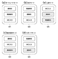
図4は、図3に示す測距点優先度選択部113によって切り替えられる撮影モード設定メニューの一例を示す図である。そして、図4(a)はポートレートモードを示す図であり、図4(b)は旅行モードを示す図である。さらに、図4(c)は集合写真モードを示す図であり、図4(d)はスポーツモードを示す図である。また、図4(e)は三脚モードを示す図である。
FIG. 4 is a diagram showing an example of a shooting mode setting menu switched by the distance measuring point
いま、撮影モードとして、図4(a)に示すポートレートモード(第1の撮影モード)M1が設定されると、測距点優先度選択部113は第1の優先順位を顔検知部132、第2の優先順位を視線検知部110、そして、第3の優先順位を測距点選択部(MC)102とする。
Now, when the portrait mode (first shooting mode) M1 shown in FIG. 4A is set as the shooting mode, the ranging point
撮影モードとして、図4(b)に示す旅行モード(第2の撮影モード)M2が設定されると、測距点優先度選択部113は第1の優先順位を視線検知部110、第2の優先順位を顔検知部132、そして、第3の優先順位を測距点選択部(MC)102とする。
When the travel mode (second shooting mode) M2 shown in FIG. 4B is set as the shooting mode, the distance measuring point
同様にして、撮影モードとして、図4(c)に示す集合写真モード(第3の撮影モード)M3が設定されると、測距点優先度選択部113は第1の優先順位を顔検知部132、第2の優先順位を測距点選択部(MC)102、そして、第3の優先順位を視線検知部110とする。
Similarly, when the group photo mode (third shooting mode) M3 shown in FIG. 4C is set as the shooting mode, the ranging point
また、撮影モードとして、図4(d)に示すスポーツモード(第4の撮影モード)M4が設定されると、測距点優先度選択部113は第1の優先順位を視線検知部110、第2の優先順位を測距点選択部(MC)102、そして、第3の優先順位を顔検知部132とする。
When the sports mode (fourth shooting mode) M4 shown in FIG. 4D is set as the shooting mode, the distance measuring point
さらに、撮影モードとして、図4(e)に示す三脚モード(第5の撮影モード)M5が設定されると、測距点優先度選択部113は第1の優先順位を測距点選択部(MC)102、第2の優先順位を顔検知部132、そして、第3の優先順位を視線検知部110とする。
Furthermore, when the tripod mode (fifth shooting mode) M5 shown in FIG. 4E is set as the shooting mode, the distance measurement point
図示の例では、集合写真モードM3においては、第3の優先順位である視線検知部110は機能を停止される。同様に、スポーツモードM4においては、第3の優先順位である顔検知部132は機能を停止され、三脚モードM5においては、第2および第3の優先順位である顔検知部132および視線検知部110は機能を停止される。
In the illustrated example, in the group photo mode M3, the function of the line-of-
図4に示す撮影モードの設定は、前述のように測距点優先度選択部113によって行われ、例えば、ポートレートモードM1、旅行モードM2、および三脚モードM5に切り替える釦として、図1(b)に示す釦113aが用いられる。そして、ポートレートモードM1から集合写真モードM3に切り替える釦および旅行モードM2からスポーツモードM4に切り替えるための釦として、図1(b)に示す釦103bが用いられる。さらに、後述する撮影動作の際にMC入力が禁止されていると、一時的にMC入力による測距点移動を許可するための釦として釦113cが用いられる。
The shooting mode shown in FIG. 4 is set by the distance measuring point
上述の釦113a〜113cの操作による撮影モードなどの切り替えによって、ユーザはグリップ部112を握った状態で測距点優先度の選択を容易に行うことができる。そして、ユーザがファインダーを覗いている状態において撮影状況が変わった場合にも瞬時に最適な撮影モード設定に切り替えることができる。
By switching the shooting mode by operating the
図5は、図4に示す撮影モードに応じた顔判定範囲の設定を説明するための図である。 FIG. 5 is a diagram for explaining the setting of the face determination range according to the shooting mode shown in FIG.
図2で説明した測光部121(エリアセンサー)によって、ピント板118上の被写体像において顔の外形(つまり、顔領域)が検知される。なお、顔領域の検知については、例えば、特開2007−274587号公報に記載の手法が用いられる。
The photometric unit 121 (area sensor) described in FIG. 2 detects the outline of the face (that is, the face area) in the subject image on the
図5においては、ピント板118上に結像した被写体像400と顔判定範囲の大きさ402a、402b、および402c)とが示されており、ピント板118に隣接して配置された透過型液晶119には、複数の測距点401と顔判定範囲402とが表示される。そして、ここでは、顔判定範囲402において視線が検知されると、MPU130は顔判定範囲402の中心近傍の測距点401aを自動的に選択し、透過型液晶119に当該測距点401aを点灯表示する。
FIG. 5 shows a
MPU130は顔領域の横幅を基準として、撮影速度設定(単写又は連写)および測距点優先度設定(視線検知又は顔検知)に応じて顔判定範囲402を設定する。図6に示す例では、視線優先の場合には、単写および連写で顔判定範囲402はそれぞれ顔の横幅を基準として100%および150%に設定される。一方、顔優先の場合には、単写および連写で顔判定範囲402はそれぞれ顔の横幅を基準として200%および300%に設定される。
The
図4に示す撮影モードの設定においては、視線検知および顔検知の優先順位に応じて、図5に示すように顔判定範囲が異なることになる。ところで、顔検知に対応して選択された測距点と視線に対応して測距点との位置が完全に一致している場合には問題ないが、一致していない場合にはいずれの測距点を選択すればよいか判断できないという問題が生じる。一方、視線検知に応じた測距点の選定では、測距点の数が多く、これら測距点が密集していると誤検知してしまう可能性がある。このため、視線検知および顔検知の優先順位に応じて顔判定範囲を異ならせている。 In the setting of the shooting mode shown in FIG. 4, the face determination range is different as shown in FIG. 5 in accordance with the priority order of the gaze detection and the face detection. By the way, there is no problem if the distance measurement point selected corresponding to face detection and the distance measurement point corresponding to the line of sight are completely coincident with each other. There arises a problem that it is not possible to determine whether to select a distance point. On the other hand, in the selection of distance measuring points according to the line-of-sight detection, there are many distance measuring points, and there is a possibility of erroneous detection if these distance measuring points are dense. For this reason, the face determination ranges are made different according to the priority order of line-of-sight detection and face detection.
さらに、視線は視野内を確認するため移動することが多いので、撮影したい顔から視線が外れてしまう可能性がある。よって、撮影者が意図的に顔から視線を外しているのか否かを適切に判断するため、視線検知および顔検知の優先順位に応じて顔判定範囲を異ならせる。 Furthermore, since the line of sight often moves to confirm the inside of the field of view, the line of sight may deviate from the face to be photographed. Therefore, in order to appropriately determine whether or not the photographer intentionally removes the line of sight from the face, the face determination range is varied according to the priority order of the line of sight detection and face detection.
例えば、顔検知の優先度が視線検知の優先度より高いと、図5に示すように、顔判定範囲は広く設定される。これによって、視線が顔から外れた場合、被写体が小さい場合、被写体が横を向いた場合などに顔判定範囲が小さくなっても、顔判定範囲が拡大されるので被写体の顔に測距点を継続して合わせことができる。 For example, if the priority of face detection is higher than the priority of gaze detection, the face determination range is set wide as shown in FIG. As a result, even if the face determination range becomes small, such as when the line of sight deviates from the face, when the subject is small, or when the subject is looking sideways, the face determination range is expanded, so a distance measurement point is added to the subject's face. Can be matched continuously.
さらに、撮影速度設定が連写に設定されている場合には、単写の場合よりも顔判定範囲を広く設定する。これによって、連写の際に視線が被写体の顔から外れても、顔判定範囲が広く設定されているので、顔領域の中心に測距点を移動できる確率を高くすることができる。 Furthermore, when the shooting speed setting is set to continuous shooting, the face determination range is set wider than in the case of single shooting. As a result, even when the line of sight deviates from the subject's face during continuous shooting, the face determination range is set wide, so the probability that the distance measuring point can be moved to the center of the face area can be increased.
なお、ここでは、顔検知に応じた顔判定範囲および視線検知によって選定された測距点については、測距点表示枠が顔判定範囲に一部でも含まれていれば顔検知による判定とするが、顔検知に応じた顔判定範囲と視線検知による測距点との関係はこれに限定されるものではない。また、顔検知ではなく、被写体の色および目などの特徴点、被写体の形状などによる被写体検知情報を用いて被写体の判定範囲を決定するようにしてもよい。そして、顔検知に応じた顔判定範囲を非表示とするようにしてもよい。 It should be noted that here, the face determination range according to face detection and the distance measurement points selected by line-of-sight detection are determined by face detection if the distance measurement point display frame is partially included in the face determination range. However, the relationship between the face determination range corresponding to the face detection and the distance measuring point based on the gaze detection is not limited to this. Further, instead of face detection, the subject determination range may be determined using subject detection information based on subject color, feature points such as eyes, subject shape, and the like. And you may make it hide the face determination range according to face detection.
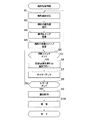
図6は、図2および図3に示すカメラにおける撮影処理を説明するためのフローチャートである。なお、図6に示すフローチャートに係る処理は、MPU130の制御下で行われる。
FIG. 6 is a flowchart for explaining a photographing process in the camera shown in FIGS. 2 and 3. Note that the processing according to the flowchart shown in FIG. 6 is performed under the control of the
いま、カメラの電源がオンされて、撮影者が撮影速度設定を行う(ステップS1)。続いて、撮影者は図4に示す撮影モード、つまり、測距点優先度の選択を行う(ステップS2)。これによって、MPU130は、図5で説明したようにして顔判定エリア(顔判定領域)を設定する(ステップS4)。続いて、撮影者が測距点移動ステップ変更部134によって測距点移動ステップを設定する(ステップS4)。
Now, the camera is turned on and the photographer sets the shooting speed (step S1). Subsequently, the photographer selects the photographing mode shown in FIG. 4, that is, the focus detection point priority (step S2). Thus, the
次に、MPU130は測距スイッチ101がオンとなったか否かを判定する(ステップS5)。測距スイッチ101がオンとならないと、つまり、測距スイッチ101がオフであると(ステップS5において、NO)、MPU130はステップS1の処理に戻って、ユーザによる撮影速度設定を待つ。なお、上記の各設定値が予めカメラに設定されている設定値から変更が無ければ、ステップS1〜S4の設定変更は行われない。
Next, the
測距スイッチ101がオンとなると(ステップS5において、YES)、タイマー135がカウントを開始する。そして、MPU130は、後述する測距点優先別の選択フロー処理を行う(ステップS6)。タイマー135がカウントアップすると(ステップS7)、MPU130はレリーズ釦がオンされたか否かを判定する(ステップS8)。
When
レリーズ釦がオンされないと(ステップS8において、NO)、MPU130はステップS5の処理に戻って、測距スイッチ101がオンであるか否かを判定する。レリーズ釦がオンされると(ステップS8において、YES)、MPU130は絞りおよびシャッター速度を制御して露出制御を行う(ステップS9)。そして、MPU130は撮像素子125を露光して撮像を行って(ステップS10)、撮影処理を終了する。
If the release button is not turned on (NO in step S8), the
なお、図示はしないが、撮影速度設定が連写の場合には、MPU130はステップS5の処理に戻る。また、ステップS8において、所定のタイマー時間までにレリーズ釦がオンされないと、前述のように、MPU130はステップS5の処理に戻ることになる。
Although not shown, when the shooting speed setting is continuous shooting, the
上述のタイマー135がカウントアップする所定のタイマー時間は、例えば、測距点優先度設定に応じて任意に設定することができる。例えば、被写体が移動している場合に、測距スタート釦101を押して測距しつつ被写体を追尾するようなときには、タイマー時間を短く設定して顔検知および視線検知の周期を短くして追従性を良好にする。具体的には、MPU130がカメラのパンニングを検知した場合や、撮影速度設定が連写に設定されている場合に、自動的にタイマー時間を短くする。
The predetermined timer time counted up by the timer 135 can be arbitrarily set according to, for example, the distance measuring point priority setting. For example, when the subject is moving and the subject is tracked while pressing the distance
また、撮影モード設定においてポートレートモードが設定されているか又は撮影速度設定が単写に設定されていると、MPU130はタイマー時間を長くして顔検知および視線検知の周期を長くして測距点が次々と移動することを防止する。
In addition, when the portrait mode is set in the shooting mode setting or the shooting speed setting is set to single shooting, the
図7は、撮影モードおよび撮影速度設定に応じたタイマー時間の比率を示す図である。なお、図7においては、予め定められたタイマー時間(つまり、標準時間)に対する比率が示されている。 FIG. 7 is a diagram illustrating the ratio of the timer time according to the shooting mode and the shooting speed setting. In FIG. 7, a ratio to a predetermined timer time (that is, standard time) is shown.
図7において、撮影速度設定が単写の場合には、撮影モードが集合写真モードであると比率が最も大きくなり、スポーツモードであると比率が最も小さくなる。同様に、撮影速度設定が連写の場合においても、撮影モードが集合写真モードであると比率が最も大きくなり、スポーツモードであると比率が最も小さくなるが、連写の場合には、単写よりも比率が小さくされる。 In FIG. 7, when the shooting speed setting is single shooting, the ratio is the highest when the shooting mode is the group photo mode, and the ratio is the lowest when the shooting mode is the sport mode. Similarly, when the shooting speed is set to continuous shooting, the ratio is the highest when the shooting mode is the group photo mode, and the ratio is the lowest when the shooting mode is the sport mode. The ratio is made smaller.
ポートレートモードと集合写真モード、そして、旅行モードとスポーツモードとを比較すると、顔検知および視線検知の双方による判定を行う場合には、タイマー時間を長くして測距点がゆっくりと切り替わるようにする。これによって、MCによる操作も行えるようにする。 When comparing portrait mode and group photo mode, and travel mode and sport mode, when making judgments based on both face detection and gaze detection, the timer time is lengthened so that the ranging point switches slowly. To do. Thereby, the operation by the MC can also be performed.
一方、ポートレートモードと旅行モード、そして、集合写真モードとスポーツモードとを比較すると、視線検知の優先度が高い撮影モードにおいてはタイマー時間を短くして次々に測距点が切り替わるようにする。さらに、単写から連写に撮影速度設定を切り替えると、前述のようにして、各撮影モードにおけるタイマー時間を短くして追従性を向上させる。 On the other hand, when the portrait mode and the travel mode are compared, and the group photo mode and the sport mode are compared, in the photographing mode having a high priority of the line-of-sight detection, the timer time is shortened so that the ranging points are switched one after another. Furthermore, when the shooting speed setting is switched from single shooting to continuous shooting, as described above, the timer time in each shooting mode is shortened to improve followability.
なお、図7に示す撮影モード設定におけるタイマー時間の比率は一例であり、例えば、比率ではなく秒の単位とするようにしてもよい。また、連写において駒速設定に応じてタイマー時間を異ならせるようにしてもよい。 Note that the ratio of the timer time in the shooting mode setting shown in FIG. 7 is an example, and for example, the unit of seconds may be used instead of the ratio. In continuous shooting, the timer time may be varied according to the frame speed setting.
図8は、図6に示す測距点優先別の選択フローの第1の例を説明するためのフローチャートである。 FIG. 8 is a flowchart for explaining a first example of the selection flow by priority of distance measurement points shown in FIG.
図8においては、撮影モード設定でポートレートモードが選択設定されたとする。ポートレートモードが開始されると、MPU130は顔検知部132によって顔領域が検知されたか否かを判定する(ステップS101)。顔領域が検知されると(ステップS101において、YES)、MPU130は視線検知部110によって視線が検知されたか否かを判定する(ステップS102)。
In FIG. 8, it is assumed that the portrait mode is selected and set in the shooting mode setting. When the portrait mode is started, the
視線が検知されると(ステップS102において、YES)、MPU130は顔判定範囲において視線が検知されているか否かを判定する。つまり、MPU130は顔と視線とが一致しているか否かを判定する(ステップS103)。ここでは、図5で説明したように、顔優先であるので、MPU130は単写モードの場合には顔の幅の200%、連写モードの場合には顔の幅の300%までの矩形範囲(顔判定範囲)で視線が検知されているか否かを判定する。
When the line of sight is detected (YES in step S102), the
顔判定範囲において視線が検知されると(ステップS103において、YES)、MPU130は顔中心測距点を選択する(ステップS104)。続いて、MPU130はMCによる測距点移動指示があると測距点を点滅状態として1ステップずつ測距点の移動ができるようにする(ステップS105)。
When a line of sight is detected in the face determination range (YES in step S103), the
ここでは、測距点の移動が許可される時間がタイマー設定されて、当該設定されたタイマー時間以下でMCによる測距点の移動が可能となる。なお、測距点を点滅させるのは一時的な移動許可であることを撮影者に知らせるためであって、一時的な移動許可であることを報知できれば、点滅以外の手法を用いてもよい。 Here, a time during which the movement of the distance measuring point is permitted is set as a timer, and the distance measuring point can be moved by the MC within the set timer time. Note that the distance measuring point blinks in order to inform the photographer that permission for temporary movement is allowed, and any technique other than blinking may be used as long as it is possible to notify that permission for temporary movement is available.
測距点が確定すると、MPU130は測距部123による測距および測光部121による測光を行って(ステップS106)、測距結果に応じてフォーカスレンズを駆動して被写体に焦点を合わせる(ステップS107)。そして、MPU130は図6に示すステップS7の処理に戻る。
When the distance measurement point is determined, the
顔領域が検知されないと(ステップS101において、NO)、MPU130は、後述するスポーツモードに移行する(ステップS108)。また、視線が検知されないと(ステップS102において、NO)、MPU130は、後述する集合写真モードに移行する(ステップS109)。顔判定範囲において視線が検知されないと(ステップS103において、NO)、MPU130は視線位置に至近の測距点を選択して(ステップS110)、ステップS106の処理に進む。
If the face area is not detected (NO in step S101), the
図9は、図8に示すポートレートモード処理においてファインダー内の測距点の移動の様子について一例を説明するための図である。そして、図9(a)は測距点移動の一例を示す図であり、図9(b)は測距点移動の他の例を示す図である。 FIG. 9 is a diagram for explaining an example of the movement of the distance measuring point in the viewfinder in the portrait mode process shown in FIG. FIG. 9A is a diagram showing an example of distance measurement point movement, and FIG. 9B is a diagram showing another example of distance measurement point movement.
図9(a)に示す例では、撮影範囲において2つの顔領域が検知されており、これら顔領域についてそれぞれ顔判定範囲M101aおよびM101bが設定されている。ここで、視線検知による至近測距点が測距点M102aであるとすると、当該測距点M102aは顔判定範囲M101aに含まれるので、MPU130は測距点として顔中心近傍の測距点M104aを選択される。
In the example shown in FIG. 9A, two face areas are detected in the shooting range, and face determination ranges M101a and M101b are set for these face areas, respectively. Here, assuming that the closest distance measuring point by line-of-sight detection is the distance measuring point M102a, since the distance measuring point M102a is included in the face determination range M101a, the
一方、顔判定領域M101bに関して、視線検知による至近測距点が測距点M102bであるとすると、当該測距点M102bは顔判定範囲M101bに含まれないので、MPU130は測距点を移動せず、測距点M102bを選択することになる(つまり、測距点は測距点M102bから移動しない)。
On the other hand, regarding the face determination area M101b, if the closest distance measurement point by line-of-sight detection is the distance measurement point M102b, the distance measurement point M102b is not included in the face determination range M101b, and the
このようにして、視線検知および顔検知を用いれば、的確に主要被写体を測距することができる。 In this way, if the gaze detection and the face detection are used, it is possible to accurately measure the main subject.
図9(b)に示す例では、撮影範囲において複数の測距点を含む大きな顔領域が検知され、顔判定範囲M101cが設定されている。ここで、視線検知による至近測距点が測距点M102cであるとすると、当該測距点M102cは顔判定範囲M101cに含まれるので、MPU130は顔中心近傍の測距点M104cを選択する。この際、MCによる測距点移動指示が右上方向に行われると、MPU130は測距点を測距点M105cに移動して点滅状態とする。
In the example shown in FIG. 9B, a large face area including a plurality of ranging points is detected in the shooting range, and a face determination range M101c is set. Here, assuming that the closest distance measuring point by line-of-sight detection is the distance measuring point M102c, the distance measuring point M102c is included in the face determination range M101c, and therefore the
このようにして、複数の測距点を含む場合には、視線検知と合わせて顔検知によって狙いの被写体の顔中央部近傍の測距点を選択するが、眼などの特徴点にさらに移動したい場合があるので、MPU130はMCによる移動を1ステップずつに限定して許可する。
In this way, when a plurality of distance measuring points are included, a distance measuring point in the vicinity of the center of the face of the target subject is selected by face detection together with line of sight detection. In some cases, the
なお、MCによる移動指示の位置が顔判定範囲外となる場合には、MPU130は測距点の移動を許可しない。つまり、測距点優先度設定が顔検知優先となっているので、MCによる移動指示の位置が顔判定範囲外となる場合には、MPU130は測距点の移動を許可しない。このことは、MPU130が測距点の移動範囲を制限することを意味する。
When the position of the movement instruction by the MC is out of the face determination range, the
また、顔判定範囲M101cに複数の測距点を含む場合には、MPU130は、図8に示すステップS105においてタイマー時間を長く設定して、MCによる測距点移動の時間を確保する。さらに、MPU130は図6に示すステップS7においてもタイマー時間を長く設定して、図8に示すステップS104又はステップS110において選択される測距点がゆっくりと切り替わるようにする。これによって、被写体をじっくりと測距できる。
If the face determination range M101c includes a plurality of distance measuring points, the
図10は、図8に示すポートレートモード処理においてファインダー内の測距点の移動の様子について他の例を説明するための図である。なお、図10においては被写体が移動しており、撮影速度設定が連写モードであるものとする。 FIG. 10 is a diagram for explaining another example of the movement of the distance measuring point in the finder in the portrait mode process shown in FIG. In FIG. 10, it is assumed that the subject is moving and the shooting speed setting is the continuous shooting mode.
図10に示す例では、単写モードにおいては顔判定範囲として顔判定範囲M101dが設定される。一方、連写モードにおいては顔判定範囲が広げられて顔判定範囲M101eが設定される。 In the example illustrated in FIG. 10, the face determination range M101d is set as the face determination range in the single shooting mode. On the other hand, in the continuous shooting mode, the face determination range is expanded and the face determination range M101e is set.
これによって、視線検知による至近測距点が測距点M102eで示すように、被写体と大きくずれている場合であっても、顔中心の測距点が選択されることになる。この結果、移動する被写体に対しても測距点を被写体に合わせ続けることができるようになる。そして、被写体が遠ざかって小さくなる場合および被写体が横を向いて顔判定範囲が狭くなったとしても、顔判定範囲を広げたことによって的確に測距点を選択することができる。 As a result, the focus point at the center of the face is selected even when the closest focus point by line-of-sight detection is greatly deviated from the subject as indicated by the focus point M102e. As a result, the distance measuring point can be continuously adjusted to the moving object. Then, even when the subject becomes far away and becomes smaller, and even when the subject turns to the side and the face determination range becomes narrower, the distance measurement point can be accurately selected by expanding the face determination range.
但し、運動会などにおいて、複数の人が走っている状態を連写モードで撮影する場合には、視線検知および顔検知によって特定の人物を追尾し易くなるものの、顔判定範囲を広げすぎると目標とする人物とは異なる人物に測距点が移ってしまう可能性がある。よって、顔判定範囲を任意に設定できるようにしてもよい。 However, when shooting a situation where multiple people are running in a continuous shooting mode at an athletic meet, etc., it will be easier to track a specific person by gaze detection and face detection, but if the face determination range is too wide, the target will be There is a possibility that the ranging point may be moved to a person different from the person who performs the operation. Therefore, the face determination range may be arbitrarily set.
また、図8に示すステップS105におけるタイマー時間を短く設定して、MCによる測距点移動を単写モードよりも制限するとともに、図6に示すステップS7におけるタイマー時間を短く設定して、顔検知および視線検知による測距点判定を速く行うようにする。 Further, the timer time in step S105 shown in FIG. 8 is set to be shorter to restrict the distance measuring point movement by the MC than in the single shooting mode, and the timer time in step S7 shown in FIG. In addition, the range-finding point determination by the gaze detection is performed quickly.
図11は、図6に示す測距点優先別の選択フローの第2の例を説明するためのフローチャートである。 FIG. 11 is a flow chart for explaining a second example of the selection flow for each focus detection point priority shown in FIG.
図11においては、撮影モード設定で旅行モードが選択設定されたとする。旅行モードが開始されると、まず、MPU130は視線検知部110によって視線が検知されたか否かを判定する(ステップS201)。視線検知部110によって視線が検知されると(ステップS201において、YES)、MPU130は顔検知部132によって顔領域が検知されたか否かを判定する(ステップS202)。
In FIG. 11, it is assumed that the travel mode is selected and set in the shooting mode setting. When the travel mode is started, first, the
顔領域が検知されると(ステップS202において、YES)、MPU130は顔判定範囲において視線が検知されているか否かを判定する(ステップS203)。ここでは、図5で説明したように、視線優先であるので、MPU130は単写モードの場合には顔の幅の100%、連写モードの場合には顔の幅の150%までの矩形範囲(顔判定範囲)で視線が検知されているか否かを判定する。
When the face area is detected (YES in step S202), the
顔判定範囲において視線が検知されると(ステップS203において、YES)、MPU130は顔中心測距点を選択する(ステップS204)。続いて、MPU130はMCによる測距点移動を禁止する(ステップS205)。
When the line of sight is detected in the face determination range (YES in step S203), the
旅行モードにおいては、顔判定範囲と視線検知位置との一致率の判定を厳しくしているので、MCによる測距点移動は不要であるとして、MPU130はMCによる測距点移動を禁止する。これによって、MPU130は不用意な測距点移動を防止する。
In the travel mode, since the determination of the coincidence rate between the face determination range and the line-of-sight detection position is made strict, the
一方、撮影者がMCによる測距点移動を行いたいこともあるので、ここでは、MPU130は解除釦がオンされたか否かを判定する(ステップS206)。なお、図2に示すグリップ部113に配置された釦113cがMCによる測距点の移動禁止を解除する解除釦とされる。
On the other hand, since the photographer may want to move the distance measuring point by the MC, the
解除釦がオンされないと、つまり、オフであると(ステップS206において、NO)、MPU130は測距部123による測距および測光部121による測光を行って(ステップS207)、測距結果に応じてフォーカスレンズを駆動して被写体に焦点を合わせる(ステップS208)。そして、MPU130は図6に示すステップS7の処理に戻る。
If the release button is not turned on, that is, if it is off (NO in step S206),
視線が検知されないと(ステップS201において、NO)、MPU130は、後述する集合写真モードに移行する(ステップS209)。また、顔領域が検知されないと(ステップS202において、NO)、MPU130は、後述するスポーツモードに移行する(ステップS210)。
If the line of sight is not detected (NO in step S201), the
顔判定範囲において視線が検知されないと(ステップS203において、NO)、MPU130は視線位置に至近の測距点を選択する(ステップS211)。そして、MPU130はMCによる(つまり、ユーザ操作による)測距点移動指示があると測距点を点滅状態(つまり、識別状態)として1ステップずつ測距点の移動ができるようにする(ステップS212)その後、MPU130はステップS207の処理に進む。
If the line of sight is not detected in the face determination range (NO in step S203), the
なお、解除釦がオンされると(ステップS206において、YES)、MPU130はステップS212の処理に進む。
When the release button is turned on (YES in step S206),
図12は、図11に示す旅行モード処理においてファインダー内の測距点の移動の様子を説明するための図である。そして、図12(a)は測距点移動の一例を示す図であり、図12(b)は測距点移動の他の例を示す図である。 FIG. 12 is a diagram for explaining how the distance measuring points in the viewfinder move in the travel mode process shown in FIG. FIG. 12A is a diagram illustrating an example of distance measurement point movement, and FIG. 12B is a diagram illustrating another example of distance measurement point movement.
図12(a)に示す例では、2つの顔領域が検知されており、これら顔領域についてそれぞれ顔判定範囲M202aおよびM202bが設定されている。ここで、視線検知による測距点が測距点M201aであるとすると、当該測距点M201aはいずれの顔判定範囲M202aおよび202bにも含まれないので、MPU130は測距点を測距点M201aから移動しない。
In the example shown in FIG. 12A, two face areas are detected, and face determination ranges M202a and M202b are set for these face areas, respectively. Here, assuming that the distance measuring point by line-of-sight detection is the distance measuring point M201a, since the distance measuring point M201a is not included in any of the face determination ranges M202a and 202b, the
図12(b)に示す例では、複数の測距点を含む大きな顔領域が検知され、顔判定範囲M202cが設定されている。ここで、視線検知による至近測距点が測距点M201cであるとすると、当該測距点M201cは顔判定範囲M202cに含まれるので、MPU130は顔中心近傍の測距点M204を選択する。
In the example shown in FIG. 12B, a large face area including a plurality of distance measuring points is detected, and a face determination range M202c is set. Here, assuming that the closest distance measuring point based on line-of-sight detection is the distance measuring point M201c, the distance measuring point M201c is included in the face determination range M202c, so the
一方、視線検知による至近測距点が測距点M212であると、当該測距点M212は顔判定範囲M202cに含まれないので、MPU130は測距点を測距点M212から移動しないが、MCによる測距点移動が可能となると、移動した測距点を点滅状態とする。
On the other hand, if the closest focus point by line-of-sight detection is the focus point M212, since the focus point M212 is not included in the face determination range M202c, the
このようにして、旅行モードが選択された場合には、顔判定範囲を狭くして安易に顔領域に測距点が移動しないようにしている。これによって、風景など人物以外の被写体を視線で決定しつつ、特定の人物又は家族などと視線が高い確率で一致した場合に、人物に焦点が合うようにすることができる。 In this way, when the travel mode is selected, the face determination range is narrowed so that the distance measuring point does not easily move to the face area. This makes it possible to focus on a person when a subject other than a person such as a landscape is determined by line of sight and the line of sight matches a specific person or family with a high probability.
図13は、図6に示す測距点優先別の選択フローの第3の例を説明するためのフローチャートである。 FIG. 13 is a flowchart for explaining a third example of the selection flow for each focus detection point priority shown in FIG.
図13においては、撮影モード設定で集合写真モードが選択設定されたとする。集合写真モードが開始されると、まず、MPU130は顔検知部132によって顔領域が検知されたか否かを判定する(ステップS301)。顔検知部132によって顔領域が検知されると(ステップS301において、YES)、MPU130は検知された顔領域(つまり、顔判定範囲)のうち最大の顔領域を選択する(ステップS302)。
In FIG. 13, it is assumed that the group photo mode is selected and set in the shooting mode setting. When the group photo mode is started, the
ここでは、最大の顔領域に限らず、例えば、至近に位置する顔領域又は画像において中央に位置する顔領域を選択するようにしてもよい。 Here, the face area is not limited to the maximum face area. For example, a face area located close to the face area or a face area located in the center of the image may be selected.
続いて、MPU130はMCの操作による測距点移動があるか否かを判定する(ステップS303)。MCの操作があると(ステップS303において、YES)、MPU130はMC操作によって移動する測距点の移動方向に顔領域が存在するか否かを判定する(ステップS304)。
Subsequently, the
測距点の移動方向に顔領域が存在すると(ステップS305において、YES)、MPU130は当該移動方向において移動前の測距点に至近の顔中心に測距点を移動する(ステップS305)。そして、MPU130は測距部123による測距および測光部121による測光を行って(ステップS306)、測距結果に応じてフォーカスレンズを駆動して被写体に焦点を合わせる(ステップS307)。そして、MPU130は図6に示すステップS7の処理に戻る。
If a face area exists in the movement direction of the distance measurement point (YES in step S305), the
顔検知部132によって顔領域が検知されないと(ステップS301において、NO)、MPU130は、後述する三脚モードに移行する(ステップS308)。また、MCの操作がないと(ステップS303において、NO)、MPU130はステップS306の処理に進む。
If the face area is not detected by the face detection unit 132 (NO in step S301), the
測距点の移動方向に顔領域が存在しないと(ステップS305において、NO)、MPU130は予め設定された移動ステップ量で測距点をMC操作によって指定された移動方向に測距点を移動させる(ステップS309)。この際、MPU130は測距点を点滅させて、顔領域が検知されずに測距点を移動したこと撮影者に知らせる。その後、MPU130はステップS306の処理に進む。
If there is no face area in the movement direction of the distance measurement point (NO in step S305), the
なお、測距点の移動が許可される時間は、タイマーによって設定され、タイマーに設定された時間以下であればMCによる測距点移動を行うことができる。 Note that the time during which the movement of the distance measuring point is permitted is set by a timer, and if the time is less than the time set in the timer, the distance measuring point can be moved by the MC.
図14は、図13に示す集合写真モード処理においてファインダー内の測距点の移動の様子を説明するための図である。 FIG. 14 is a diagram for explaining how the distance measuring points in the viewfinder move in the group photo mode process shown in FIG.
図14に示す例では、3つの顔領域が検知されており、これら顔領域についてそれぞれ顔判定範囲M301a、M301b、およびM301cが設定されている。ここでは、顔判定範囲M301aが最大の顔判定範囲であるので、MPU130は顔検知範囲M301aにおける中心測距点を測距点M302として選択する。
In the example shown in FIG. 14, three face areas are detected, and face determination ranges M301a, M301b, and M301c are set for these face areas, respectively. Here, since the face determination range M301a is the maximum face determination range, the
ここで、MC操作によって右方向の移動が指示されると、MPU130は移動方向において至近の顔判定範囲は顔判定範囲M301bであるので、測距点M305を選択する。また、MC操作によって下方向の移動が指示されると、MCの指示方向には顔検知範囲が存在しないので、MPU130は予め設定されたステップ量(例えば、3ステップ)で測距点M310を移動させて、当該測距点を点滅状態とする。
Here, when a rightward movement is instructed by the MC operation, the
このようにして、集合写真モードが選択された場合には、MC操作に応じて顔判定範囲を選択できるようにして、多人数を撮影する場合又は人ごみの中で特定の人物を撮影する場合において顔判定範囲の選択を容易とする。 In this way, when the group photo mode is selected, the face determination range can be selected according to the MC operation, and when shooting a large number of people or shooting a specific person in the crowd Facilitates selection of face determination range.
図15は、図6に示す測距点優先別の選択フローの第4の例を説明するためのフローチャートである。 FIG. 15 is a flowchart for explaining a fourth example of the selection flow by priority of distance measurement points shown in FIG.
図15においては、撮影モード設定でスポーツモードが選択設定されたとする。スポーツモードが開始されると、まず、MPU130は視線検知部110によって視線が検知されたか否かを判定する(ステップS401)。視線検知部110によって視線が検知されると(ステップS401において、YES)、MPU130は、検知された視線に至近の測距点を選択する(ステップS402)。
In FIG. 15, it is assumed that the sport mode is selected and set in the shooting mode setting. When the sport mode is started, first, the
続いて、MPU130はMCの操作による測距点移動があるか否かを判定する(ステップS403)。MCの操作があると(ステップS403において、YES)、MPU130は測距点を点滅状態として1ステップずつ測距点の移動ができるようにする(ステップS404)。
Subsequently, the
ステップS404においては、MPU130は測距点を点滅させて、測距点が視線検知位置と異なる位置に移動したことを撮影者に知らせる。この際には、測距点の移動が許可される時間は、タイマーによって設定され、設定されたタイマー時間以下であればMC操作による測距点の移動を行うことができる。なお、ここで許可されるタイマー時間は他の撮影モードに比べて最も短い時間に設定される。
In step S404, the
その後、MPU130は測距部123による測距および測光部121による測光を行って(ステップS405)、測距結果に応じてフォーカスレンズを駆動して被写体に焦点を合わせる(ステップS406)。そして、MPU130は図6に示すステップS7の処理に戻る。
Thereafter, the
視線検知部110によって視線が検知されないと(ステップS401において、NO)、MPU130は、後述する三脚モードに移行する(ステップS407)。また、MCの操作がないと(ステップS403において、NO)、MPU130はステップS405の処理に進む。
If the line-of-
図16は、図15に示すスポーツモード処理においてファインダー内の測距点の移動の様子を説明するための図である。 FIG. 16 is a diagram for explaining how the distance measuring point in the finder moves in the sport mode process shown in FIG.
図16に示す例では、視線検知に応じて測距点M402が選択されている。ここで、MC操作によって測距点を左下方向に移動させる指示があると、MPU130は測距点M402を測距点M404に移動して、当該測距点を点滅状態とする。
In the example shown in FIG. 16, the distance measuring point M402 is selected according to the line-of-sight detection. Here, if there is an instruction to move the distance measuring point in the lower left direction by the MC operation, the
このようにして、スポーツモードが選択された場合には、顔又は特定の被写体の検知による測距点選択を許可せずに、撮影モード別のタイマー設定においても最短時間を設定する。これによって、視線およびMC操作による瞬時の測距点移動が可能となって、例えば、カーレース、鉄道、サッカー、又は陸上競技など高速移動被写体を撮影する場合に適している。 In this way, when the sports mode is selected, the shortest time is set even in the timer setting for each shooting mode without permitting the selection of a distance measuring point by detecting a face or a specific subject. As a result, the distance measuring point can be instantaneously moved by the line of sight and the MC operation, which is suitable for shooting a high-speed moving subject such as a car race, railway, soccer, or athletics.
図17は、図6に示す測距点優先別の選択フローの第5の例を説明するためのフローチャートである。 FIG. 17 is a flowchart for explaining a fifth example of the selection flow for each focus detection point priority shown in FIG.
図17においては、撮影モード設定で三脚モードが選択設定されたとする。三脚モードが開始されると、まず、MPU130はMCの操作による測距点移動があるか否かを判定する(ステップS501)。MCの操作があると(ステップS501において、YES)、MPU130は予め設定された移動ステップ量で測距点をMC操作によって指定された移動方向に測距点を移動させる(ステップS502)。この際、MPU130は測距点を点滅させて、顔領域が検知されずに測距点を移動したこと撮影者に知らせる。
In FIG. 17, it is assumed that the tripod mode is selected and set in the shooting mode setting. When the tripod mode is started, the
その後、MPU130は測距部123による測距および測光部121による測光を行って(ステップS503)、測距結果に応じてフォーカスレンズを駆動して被写体に焦点を合わせる(ステップS504)。そして、MPU130は図6に示すステップS7の処理に戻る。
Thereafter, the
MCの操作がないと(ステップS501において、NO)、MPU130は測距点を自動選択とする(ステップS505)。この際には、MPU130は予め設定されたアルゴリズムに応じて測距点を決定する。例えば、MPU130は至近合焦被写体を選択するか又は無限遠に合わせる。そして、MPU130はステップS503の処理に進む。
If there is no MC operation (NO in step S501), the
このようにして、三脚モードが選択された場合には、顔検知および視線検知による測距点移動を許可せず、MC操作による任意のステップ数で測距点移動を可能とする。この結果、風景などを撮影する際、カメラを三脚に固定して撮影する場合に適している。 In this way, when the tripod mode is selected, the distance measuring point movement by the face detection and the line-of-sight detection is not permitted, and the distance measuring point can be moved by an arbitrary number of steps by the MC operation. As a result, it is suitable for shooting a landscape or the like with the camera fixed on a tripod.
上述の実施の形態では、光学機器としてデジタルカメラなどの1眼レフカメラを例に挙げて説明したが、カメラ機能を備える電子機器であれば、同様にして本発明を適用することができる。 In the above-described embodiment, a single-lens reflex camera such as a digital camera has been described as an example of an optical device. However, the present invention can be similarly applied to any electronic device having a camera function.
なお、図13および図17においては、MC操作による任意のステップ数で測距点を移動する例について説明したが、MC操作による移動指示方向に移動可能な測距点が存在しない場合には、画面の端点まで測距点を移動する。 13 and 17, the example has been described in which the distance measurement point is moved by an arbitrary number of steps by the MC operation. However, when there is no distance measurement point that can be moved in the movement instruction direction by the MC operation, Move the AF point to the end point of the screen.
さらに、本発明の実施の形態では、レンズ交換式の一眼レフカメラを例に挙げて説明したが、撮影レンズがカメラ本体と一体となったカメラについても同様にして本実施の形態を適用することができる。 Furthermore, in the embodiment of the present invention, the description has been given by taking the lens interchangeable single-lens reflex camera as an example. Can do.
また、本発明の実施の形態では、ペンタプリズムなどを用いた光学ファインダーを備えるカメラを例に挙げて説明したが、例えば、EVF装置に対して視線入力装置を取り付けたカメラにおいても同様にして本実施の形態を適用することができる。 In the embodiment of the present invention, a camera having an optical viewfinder using a pentaprism or the like has been described as an example. However, for example, a camera in which a line-of-sight input device is attached to an EVF device is also described. Embodiments can be applied.
加えて、本発明の実施の形態では、位相差方式による焦点検出および測光素子による被写体検出を例に挙げて説明したが、撮像素子の出力を用いて焦点検出および被写体検出を行うカメラについても同様にして本実施の形態を適用することができる。 In addition, in the embodiment of the present invention, the focus detection by the phase difference method and the subject detection by the photometric element have been described as examples. Thus, the present embodiment can be applied.
以上、本発明について実施の形態に基づいて説明したが、本発明は、これらの実施の形態に限定されるものではなく、この発明の要旨を逸脱しない範囲の様々な形態も本発明に含まれる。 As mentioned above, although this invention was demonstrated based on embodiment, this invention is not limited to these embodiment, Various forms of the range which does not deviate from the summary of this invention are also contained in this invention. .
例えば、上記の実施の形態の機能を制御方法として、この制御方法を光学機器に実行させるようにすればよい。また、上述の実施の形態の機能を有するプログラムを制御プログラムとして、当該制御プログラムを光学機器が備えるコンピュータに実行させるようにしてもよい。なお、制御プログラムは、例えば、コンピュータに読み取り可能な記録媒体に記録される。 For example, the function of the above embodiment may be used as a control method, and this control method may be executed by an optical apparatus. In addition, a program having the functions of the above-described embodiments may be used as a control program, and the control program may be executed by a computer included in the optical device. The control program is recorded on a computer-readable recording medium, for example.
また、本発明は、以下の処理を実行することによっても実現される。つまり、上述した実施形態の機能を実現するソフトウェア(プログラム)を、ネットワーク又は各種の記録媒体を介してシステム或いは装置に供給し、そのシステム或いは装置のコンピュータ(またはCPUやMPUなど)がプログラムを読み出して実行する処理である。 The present invention can also be realized by executing the following processing. That is, software (program) that realizes the functions of the above-described embodiments is supplied to a system or apparatus via a network or various recording media, and the computer (or CPU, MPU, etc.) of the system or apparatus reads the program. To be executed.
101 測距スタート釦
102 測距点選択部
109 ファインダー
110 視線検知部
111 レリーズ釦
113 測距点優先度変更部
119 透過型液晶
121 測光部
123 測距部
130 MPU
DESCRIPTION OF
Claims (15)
撮影者の眼をモニターして前記画像おいて目視されている位置を検出する第2の検出手段と、
複数の撮影モードから撮影モードを選択するモード選択手段と、
前記第1の検出手段によって検出された前記特定の被写体の領域に基づく第1の範囲に、前記第2の検出手段によって検出された画像において目視されている位置が含まれている場合に、前記特定の被写体の領域に基づいて複数の焦点検出領域から焦点検出領域を選択し、前記第1の範囲に、前記第2の検出手段によって検出された画像において目視されている位置が含まれていない場合に、前記画像において目視されている位置に基づいて複数の焦点検出領域から焦点検出領域を選択する領域選択手段と、有し、
前記第1の範囲は、前記モード選択手段によって選択された前記撮影モードに応じて設定されることを特徴とする光学機器。 First detecting means for detecting a region of a specific subject from an image;
A second detecting means for monitoring a photographer's eyes and detecting a position viewed in the image;
Mode selection means for selecting a shooting mode from a plurality of shooting modes;
When the first range based on the region of the specific subject detected by the first detection unit includes a position that is visually observed in the image detected by the second detection unit, A focus detection area is selected from a plurality of focus detection areas based on a specific subject area, and the first range does not include a position that is viewed in the image detected by the second detection means. A region selecting means for selecting a focus detection region from a plurality of focus detection regions based on the position being visually observed in the image ,
The optical apparatus according to claim 1, wherein the first range is set according to the photographing mode selected by the mode selection unit .
前記単写モードが設定されている場合と比較して、前記連写モードが設定されている場合の前記所定の比率を大きくすることを特徴とする請求項3に記載の光学機器。 Having setting means for setting either single shooting mode or continuous shooting mode,
The optical apparatus according to claim 3 , wherein the predetermined ratio when the continuous shooting mode is set is increased as compared with a case where the single shooting mode is set.
撮影者による指示に応じた前記焦点検出領域の選択範囲を規制する規制手段と、を有し、
前記規制手段は、前記特定の被写体の領域が検出されている場合、前記選択範囲を前記第1の範囲に規制することを特徴とする請求項1〜4のいずれか1項に記載の光学機器。 A selection means for selecting a focus detection area in accordance with an instruction from the photographer;
Regulation means for regulating the selection range of the focus detection area according to an instruction from the photographer
Before SL regulating means, when the region of the specific subject is detected, before describing the hexene-option range to any one of claims 1-4, characterized by regulating the first range Optical equipment.
撮影者の眼をモニターして前記画像おいて目視されている位置を検出する第2の検出手段と、A second detecting means for monitoring a photographer's eyes and detecting a position viewed in the image;
前記特定の被写体の領域を優先する第1の撮影モードと、前記画像において目視されている位置を優先する第2の撮影モードとを少なくとも含む複数の撮影モードから撮影モードを選択するモード選択手段と、Mode selection means for selecting a shooting mode from a plurality of shooting modes including at least a first shooting mode that prioritizes the area of the specific subject and a second shooting mode that prioritizes a position being viewed in the image; ,
前記モード選択手段により選択された撮影モードに応じて、複数の焦点検出領域から焦点検出領域を選択する領域選択手段と、を有することを特徴とする光学機器。An optical apparatus comprising: area selection means for selecting a focus detection area from a plurality of focus detection areas according to the photographing mode selected by the mode selection means.
撮影者による指示に応じて前記焦点検出領域を変更する際、撮影者が当該焦点検出領域を識別できるように表示する表示制御手段を有することを特徴とする請求項7に記載の光学機器。8. The optical apparatus according to claim 7, further comprising display control means for displaying the focus detection area so that the photographer can identify the focus detection area when the focus detection area is changed in accordance with an instruction from the photographer.
画像から特定の被写体の領域を検出する第1の検出ステップと、
撮影者の眼をモニターして前記画像おいて目視されている位置を検出する第2の検出ステップと、
複数の撮影モードから撮影モードを選択するモード選択ステップと、
前記第1の検出ステップで検出された前記特定の被写体の領域に基づく第1の範囲に、前記第2の検出ステップで検出された画像において目視されている位置が含まれている場合に、前記特定の被写体の領域に基づいて複数の焦点検出領域から焦点検出領域を選択し、前記第1の範囲に、前記第2の検出ステップで検出された画像において目視されている位置が含まれていない場合に、前記画像において目視されている位置に基づいて複数の焦点検出領域から焦点検出領域を選択する領域選択ステップと、有し、
前記第1の範囲は、前記モード選択ステップで選択された前記撮影モードに応じて設定されることを特徴とすることを特徴とする制御方法。 A method for controlling an optical instrument,
A first detection step of detecting a region of a specific subject from the image;
A second detection step of monitoring a photographer's eyes and detecting a position viewed in the image;
A mode selection step for selecting a shooting mode from a plurality of shooting modes;
When the first range based on the region of the specific subject detected in the first detection step includes a position visually observed in the image detected in the second detection step, A focus detection area is selected from a plurality of focus detection areas based on a specific subject area, and the first range does not include a position that is viewed in the image detected in the second detection step. A region selection step of selecting a focus detection region from a plurality of focus detection regions based on the position being viewed in the image ,
The first range is set according to the photographing mode selected in the mode selection step .
前記光学機器が備えるコンピュータに、
画像から特定の被写体の領域を検出する第1の検出ステップと、
撮影者の眼をモニターして前記画像おいて目視されている位置を検出する第2の検出ステップと、
複数の撮影モードから撮影モードを選択するモード選択ステップと、
前記第1の検出ステップで検出された前記特定の被写体の領域に基づく第1の範囲に、前記第2の検出ステップで検出された画像において目視されている位置が含まれている場合に、前記特定の被写体の領域に基づいて複数の焦点検出領域から焦点検出領域を選択し、前記第1の範囲に、前記第2の検出ステップで検出された画像において目視されている位置が含まれていない場合に、前記画像において目視されている位置に基づいて複数の焦点検出領域から焦点検出領域を選択する領域選択ステップと、実行させ、
前記第1の範囲は、前記モード選択ステップで選択された前記撮影モードに応じて設定されることを特徴とすることを特徴とする制御プログラム。 A control program used in an optical device,
In the computer provided in the optical device,
A first detection step of detecting a region of a specific subject from the image;
A second detection step of monitoring a photographer's eyes and detecting a position viewed in the image;
A mode selection step for selecting a shooting mode from a plurality of shooting modes;
When the first range based on the region of the specific subject detected in the first detection step includes a position visually observed in the image detected in the second detection step, A focus detection area is selected from a plurality of focus detection areas based on a specific subject area, and the first range does not include a position that is viewed in the image detected in the second detection step. A region selection step of selecting a focus detection region from a plurality of focus detection regions based on the position being viewed in the image ,
The control program according to claim 1, wherein the first range is set in accordance with the photographing mode selected in the mode selection step .
画像から特定の被写体の領域を検出する第1の検出ステップと、A first detection step of detecting a region of a specific subject from the image;
撮影者の眼をモニターして前記画像おいて目視されている位置を検出する第2の検出ステップと、A second detection step of monitoring a photographer's eyes and detecting a position viewed in the image;
前記特定の被写体の領域を優先する第1の撮影モードと、前記画像において目視されている位置を優先する第2の撮影モードとを少なくとも含む複数の撮影モードから撮影モードを選択するモード選択ステップと、A mode selection step of selecting a shooting mode from a plurality of shooting modes including at least a first shooting mode that prioritizes the area of the specific subject and a second shooting mode that prioritizes a position viewed in the image; ,
前記モード選択ステップで選択された撮影モードに応じて、複数の焦点検出領域から焦点検出領域を選択する領域選択ステップと、を有することを特徴とする制御方法。And a region selection step of selecting a focus detection region from a plurality of focus detection regions according to the photographing mode selected in the mode selection step.
前記光学機器が備えるコンピュータに、In the computer provided in the optical device,
画像から特定の被写体の領域を検出する第1の検出ステップと、A first detection step of detecting a region of a specific subject from the image;
撮影者の眼をモニターして前記画像おいて目視されている位置を検出する第2の検出ステップと、A second detection step of monitoring a photographer's eyes and detecting a position viewed in the image;
前記特定の被写体の領域を優先する第1の撮影モードと、前記画像において目視されている位置を優先する第2の撮影モードとを少なくとも含む複数の撮影モードから撮影モードを選択するモード選択ステップと、A mode selection step of selecting a shooting mode from a plurality of shooting modes including at least a first shooting mode that prioritizes the area of the specific subject and a second shooting mode that prioritizes a position viewed in the image; ,
前記モード選択ステップで選択された撮影モードに応じて、複数の焦点検出領域から焦点検出領域を選択する領域選択ステップと、を実行させることを特徴とする制御プログラム。An area selection step of selecting a focus detection area from a plurality of focus detection areas according to the shooting mode selected in the mode selection step.
Priority Applications (2)
| Application Number | Priority Date | Filing Date | Title |
|---|---|---|---|
| JP2013151477A JP6257198B2 (en) | 2013-07-22 | 2013-07-22 | Optical apparatus, control method therefor, and control program |
| US14/335,407 US9445005B2 (en) | 2013-07-22 | 2014-07-18 | Optical device capable of selecting focus detection point, method of controlling the same, and storage medium |
Applications Claiming Priority (1)
| Application Number | Priority Date | Filing Date | Title |
|---|---|---|---|
| JP2013151477A JP6257198B2 (en) | 2013-07-22 | 2013-07-22 | Optical apparatus, control method therefor, and control program |
Publications (3)
| Publication Number | Publication Date |
|---|---|
| JP2015022207A JP2015022207A (en) | 2015-02-02 |
| JP2015022207A5 JP2015022207A5 (en) | 2016-10-13 |
| JP6257198B2 true JP6257198B2 (en) | 2018-01-10 |
Family
ID=52486686
Family Applications (1)
| Application Number | Title | Priority Date | Filing Date |
|---|---|---|---|
| JP2013151477A Active JP6257198B2 (en) | 2013-07-22 | 2013-07-22 | Optical apparatus, control method therefor, and control program |
Country Status (1)
| Country | Link |
|---|---|
| JP (1) | JP6257198B2 (en) |
Families Citing this family (6)
| Publication number | Priority date | Publication date | Assignee | Title |
|---|---|---|---|---|
| JP6799063B2 (en) * | 2016-07-20 | 2020-12-09 | 富士フイルム株式会社 | Attention position recognition device, image pickup device, display device, attention position recognition method and program |
| JP6862202B2 (en) | 2017-02-08 | 2021-04-21 | キヤノン株式会社 | Image processing device, imaging device and control method |
| JP7425562B2 (en) * | 2019-08-14 | 2024-01-31 | キヤノン株式会社 | Imaging device and its control method |
| JP7208128B2 (en) * | 2019-10-24 | 2023-01-18 | キヤノン株式会社 | Imaging device and its control method |
| JP7547062B2 (en) | 2020-03-25 | 2024-09-09 | キヤノン株式会社 | Imaging device |
| JP7518684B2 (en) | 2020-07-16 | 2024-07-18 | キヤノン株式会社 | Imaging control device, control method thereof, program and recording medium |
Family Cites Families (10)
| Publication number | Priority date | Publication date | Assignee | Title |
|---|---|---|---|---|
| JPH06138378A (en) * | 1992-10-28 | 1994-05-20 | Canon Inc | Camera provided with focus detecting means and line-of-sight detecting means |
| TW247985B (en) * | 1993-04-22 | 1995-05-21 | Canon Kk | Image-taking apparatus |
| JPH06308372A (en) * | 1993-04-22 | 1994-11-04 | Canon Inc | Camera with line of sight detecting function |
| JP2001116985A (en) * | 1999-10-21 | 2001-04-27 | Canon Inc | Camera with subject recognizing function and subject recognizing method |
| JP4970716B2 (en) * | 2004-09-01 | 2012-07-11 | 株式会社ニコン | Electronic camera |
| JP2006345503A (en) * | 2005-05-11 | 2006-12-21 | Fujifilm Holdings Corp | Imaging apparatus, imaging method, image processing apparatus, image processing method and program |
| EP1900196B1 (en) * | 2005-05-11 | 2012-03-21 | FUJIFILM Corporation | Image capturing apparatus, image capturing method and program |
| JP2008124846A (en) * | 2006-11-14 | 2008-05-29 | Fujifilm Corp | Photographing device, method, and program |
| JP4902460B2 (en) * | 2007-08-08 | 2012-03-21 | キヤノン株式会社 | Image processing apparatus, imaging apparatus, and image processing method |
| JP5871175B2 (en) * | 2011-07-22 | 2016-03-01 | 株式会社ニコン | Region extraction device, imaging device, and region extraction program |
-
2013
- 2013-07-22 JP JP2013151477A patent/JP6257198B2/en active Active
Also Published As
| Publication number | Publication date |
|---|---|
| JP2015022207A (en) | 2015-02-02 |
Similar Documents
| Publication | Publication Date | Title |
|---|---|---|
| JP6257199B2 (en) | Optical apparatus, control method therefor, and control program | |
| US9445005B2 (en) | Optical device capable of selecting focus detection point, method of controlling the same, and storage medium | |
| JP6257198B2 (en) | Optical apparatus, control method therefor, and control program | |
| JP6486109B2 (en) | EXPOSURE CONTROL DEVICE, ITS CONTROL METHOD, AND PROGRAM | |
| US10863079B2 (en) | Control apparatus, image capturing apparatus, and non-transitory computer-readable storage medium | |
| US5510875A (en) | Representation of depth of field in camera | |
| JP2002152558A (en) | Camera | |
| JP2008211630A (en) | Imaging apparatus | |
| JP2003029135A (en) | Camera, camera system and photographic lens device | |
| JP2008170645A (en) | Focus controller and imaging apparatus | |
| JPH0862486A (en) | Automatic focusing device and automatic focusing method | |
| US20160100105A1 (en) | Interchangeable lens, image capturing apparatus and storage medium storing control program | |
| JP2004053686A (en) | Method for controlling camera and focusing device | |
| JP2002214659A (en) | Camera with shake correcting function | |
| JPH11352570A (en) | Camera | |
| JP2008191391A (en) | Focusing mechanism, and camera | |
| JP6544936B2 (en) | Control device of imaging device, imaging device and control method thereof | |
| JP2017021177A (en) | Range-finding point upon lens vignetting, range-finding area transition method | |
| JP2010282107A (en) | Imaging apparatus and control method therefor | |
| JP3186212B2 (en) | Eye-gaze input camera | |
| JP2016065998A (en) | Imaging device and imaging program | |
| JPH07311331A (en) | Camera provided with line-of-sight detection device | |
| JP2006098676A (en) | Autofocus camera | |
| JPH07301742A (en) | Camera | |
| JPH03107932A (en) | Photographing controller for camera |
Legal Events
| Date | Code | Title | Description |
|---|---|---|---|
| A521 | Request for written amendment filed |
Free format text: JAPANESE INTERMEDIATE CODE: A523 Effective date: 20160627 |
|
| A621 | Written request for application examination |
Free format text: JAPANESE INTERMEDIATE CODE: A621 Effective date: 20160627 |
|
| A521 | Request for written amendment filed |
Free format text: JAPANESE INTERMEDIATE CODE: A523 Effective date: 20160829 |
|
| A977 | Report on retrieval |
Free format text: JAPANESE INTERMEDIATE CODE: A971007 Effective date: 20170314 |
|
| A131 | Notification of reasons for refusal |
Free format text: JAPANESE INTERMEDIATE CODE: A131 Effective date: 20170321 |
|
| A521 | Request for written amendment filed |
Free format text: JAPANESE INTERMEDIATE CODE: A523 Effective date: 20170519 |
|
| TRDD | Decision of grant or rejection written | ||
| A01 | Written decision to grant a patent or to grant a registration (utility model) |
Free format text: JAPANESE INTERMEDIATE CODE: A01 Effective date: 20171107 |
|
| A61 | First payment of annual fees (during grant procedure) |
Free format text: JAPANESE INTERMEDIATE CODE: A61 Effective date: 20171205 |
|
| R151 | Written notification of patent or utility model registration |
Ref document number: 6257198 Country of ref document: JP Free format text: JAPANESE INTERMEDIATE CODE: R151 |