JP6255401B2 - Phantom freedom for manipulating machine body movement - Google Patents
Phantom freedom for manipulating machine body movement Download PDFInfo
- Publication number
- JP6255401B2 JP6255401B2 JP2015527554A JP2015527554A JP6255401B2 JP 6255401 B2 JP6255401 B2 JP 6255401B2 JP 2015527554 A JP2015527554 A JP 2015527554A JP 2015527554 A JP2015527554 A JP 2015527554A JP 6255401 B2 JP6255401 B2 JP 6255401B2
- Authority
- JP
- Japan
- Prior art keywords
- freedom
- degrees
- joint
- machine body
- manipulator
- Prior art date
- Legal status (The legal status is an assumption and is not a legal conclusion. Google has not performed a legal analysis and makes no representation as to the accuracy of the status listed.)
- Active
Links
- 230000033001 locomotion Effects 0.000 title claims description 77
- 239000012636 effector Substances 0.000 claims description 100
- 238000000034 method Methods 0.000 claims description 54
- 238000003860 storage Methods 0.000 claims description 4
- 238000004088 simulation Methods 0.000 claims 4
- 238000005259 measurement Methods 0.000 description 43
- 210000003857 wrist joint Anatomy 0.000 description 39
- 238000001356 surgical procedure Methods 0.000 description 22
- 238000010586 diagram Methods 0.000 description 21
- 230000008569 process Effects 0.000 description 18
- 238000004364 calculation method Methods 0.000 description 15
- 230000007246 mechanism Effects 0.000 description 15
- 230000004044 response Effects 0.000 description 14
- 238000003384 imaging method Methods 0.000 description 13
- 238000013519 translation Methods 0.000 description 12
- 230000014616 translation Effects 0.000 description 12
- 210000000707 wrist Anatomy 0.000 description 12
- 239000011159 matrix material Substances 0.000 description 11
- 230000000712 assembly Effects 0.000 description 10
- 238000000429 assembly Methods 0.000 description 10
- 239000013307 optical fiber Substances 0.000 description 10
- 238000002432 robotic surgery Methods 0.000 description 9
- 230000004913 activation Effects 0.000 description 7
- 230000008859 change Effects 0.000 description 6
- 239000013598 vector Substances 0.000 description 6
- 238000013459 approach Methods 0.000 description 5
- 230000008901 benefit Effects 0.000 description 5
- 239000000835 fiber Substances 0.000 description 4
- 230000000670 limiting effect Effects 0.000 description 4
- 239000000463 material Substances 0.000 description 4
- 238000013178 mathematical model Methods 0.000 description 4
- 238000002324 minimally invasive surgery Methods 0.000 description 4
- 238000012545 processing Methods 0.000 description 4
- 210000003815 abdominal wall Anatomy 0.000 description 3
- 238000004140 cleaning Methods 0.000 description 3
- 238000003745 diagnosis Methods 0.000 description 3
- 230000006870 function Effects 0.000 description 3
- 238000013507 mapping Methods 0.000 description 3
- 238000012986 modification Methods 0.000 description 3
- 230000004048 modification Effects 0.000 description 3
- 230000002829 reductive effect Effects 0.000 description 3
- 239000000523 sample Substances 0.000 description 3
- 230000035807 sensation Effects 0.000 description 3
- 230000003213 activating effect Effects 0.000 description 2
- 230000009286 beneficial effect Effects 0.000 description 2
- 230000000694 effects Effects 0.000 description 2
- 230000005484 gravity Effects 0.000 description 2
- 238000003780 insertion Methods 0.000 description 2
- 230000037431 insertion Effects 0.000 description 2
- 238000003973 irrigation Methods 0.000 description 2
- 230000002262 irrigation Effects 0.000 description 2
- 230000003287 optical effect Effects 0.000 description 2
- 230000008447 perception Effects 0.000 description 2
- 230000001133 acceleration Effects 0.000 description 1
- 230000002411 adverse Effects 0.000 description 1
- 230000004075 alteration Effects 0.000 description 1
- 230000006399 behavior Effects 0.000 description 1
- 238000004891 communication Methods 0.000 description 1
- 239000002131 composite material Substances 0.000 description 1
- 238000010276 construction Methods 0.000 description 1
- 238000000354 decomposition reaction Methods 0.000 description 1
- 238000002405 diagnostic procedure Methods 0.000 description 1
- 230000005672 electromagnetic field Effects 0.000 description 1
- 238000002674 endoscopic surgery Methods 0.000 description 1
- 238000005516 engineering process Methods 0.000 description 1
- 238000011010 flushing procedure Methods 0.000 description 1
- 210000004247 hand Anatomy 0.000 description 1
- 210000002478 hand joint Anatomy 0.000 description 1
- 230000006872 improvement Effects 0.000 description 1
- 230000010365 information processing Effects 0.000 description 1
- 208000014674 injury Diseases 0.000 description 1
- 238000002357 laparoscopic surgery Methods 0.000 description 1
- 238000002156 mixing Methods 0.000 description 1
- 239000000203 mixture Substances 0.000 description 1
- 230000002107 myocardial effect Effects 0.000 description 1
- 210000000056 organ Anatomy 0.000 description 1
- 239000003973 paint Substances 0.000 description 1
- 230000036961 partial effect Effects 0.000 description 1
- 239000004814 polyurethane Substances 0.000 description 1
- 229920002635 polyurethane Polymers 0.000 description 1
- 238000011084 recovery Methods 0.000 description 1
- 238000002271 resection Methods 0.000 description 1
- 230000004043 responsiveness Effects 0.000 description 1
- 230000002441 reversible effect Effects 0.000 description 1
- 238000012549 training Methods 0.000 description 1
- 230000008733 trauma Effects 0.000 description 1
- 210000001835 viscera Anatomy 0.000 description 1
- 230000000007 visual effect Effects 0.000 description 1
Images


Classifications
-
- A—HUMAN NECESSITIES
- A61—MEDICAL OR VETERINARY SCIENCE; HYGIENE
- A61B—DIAGNOSIS; SURGERY; IDENTIFICATION
- A61B34/00—Computer-aided surgery; Manipulators or robots specially adapted for use in surgery
- A61B34/30—Surgical robots
- A61B34/35—Surgical robots for telesurgery
-
- B—PERFORMING OPERATIONS; TRANSPORTING
- B25—HAND TOOLS; PORTABLE POWER-DRIVEN TOOLS; MANIPULATORS
- B25J—MANIPULATORS; CHAMBERS PROVIDED WITH MANIPULATION DEVICES
- B25J9/00—Programme-controlled manipulators
- B25J9/16—Programme controls
- B25J9/1679—Programme controls characterised by the tasks executed
- B25J9/1689—Teleoperation
-
- A—HUMAN NECESSITIES
- A61—MEDICAL OR VETERINARY SCIENCE; HYGIENE
- A61B—DIAGNOSIS; SURGERY; IDENTIFICATION
- A61B34/00—Computer-aided surgery; Manipulators or robots specially adapted for use in surgery
- A61B34/30—Surgical robots
- A61B34/37—Master-slave robots
-
- B—PERFORMING OPERATIONS; TRANSPORTING
- B25—HAND TOOLS; PORTABLE POWER-DRIVEN TOOLS; MANIPULATORS
- B25J—MANIPULATORS; CHAMBERS PROVIDED WITH MANIPULATION DEVICES
- B25J9/00—Programme-controlled manipulators
- B25J9/16—Programme controls
-
- G—PHYSICS
- G05—CONTROLLING; REGULATING
- G05B—CONTROL OR REGULATING SYSTEMS IN GENERAL; FUNCTIONAL ELEMENTS OF SUCH SYSTEMS; MONITORING OR TESTING ARRANGEMENTS FOR SUCH SYSTEMS OR ELEMENTS
- G05B2219/00—Program-control systems
- G05B2219/30—Nc systems
- G05B2219/40—Robotics, robotics mapping to robotics vision
- G05B2219/40195—Tele-operation, computer assisted manual operation
-
- G—PHYSICS
- G05—CONTROLLING; REGULATING
- G05B—CONTROL OR REGULATING SYSTEMS IN GENERAL; FUNCTIONAL ELEMENTS OF SUCH SYSTEMS; MONITORING OR TESTING ARRANGEMENTS FOR SUCH SYSTEMS OR ELEMENTS
- G05B2219/00—Program-control systems
- G05B2219/30—Nc systems
- G05B2219/45—Nc applications
- G05B2219/45123—Electrogoniometer, neuronavigator, medical robot used by surgeon to operate
-
- Y—GENERAL TAGGING OF NEW TECHNOLOGICAL DEVELOPMENTS; GENERAL TAGGING OF CROSS-SECTIONAL TECHNOLOGIES SPANNING OVER SEVERAL SECTIONS OF THE IPC; TECHNICAL SUBJECTS COVERED BY FORMER USPC CROSS-REFERENCE ART COLLECTIONS [XRACs] AND DIGESTS
- Y10—TECHNICAL SUBJECTS COVERED BY FORMER USPC
- Y10S—TECHNICAL SUBJECTS COVERED BY FORMER USPC CROSS-REFERENCE ART COLLECTIONS [XRACs] AND DIGESTS
- Y10S901/00—Robots
- Y10S901/02—Arm motion controller
Description
関連出願の相互参照
本出願は、2012年8月15日に出願された米国仮特許出願第61/683,495号の利益を主張するものであり、この文献は、あらゆる目的のためにその全体を参照することにより本明細書に組み込まれる。
This application claims the benefit of US Provisional Patent Application No. 61 / 683,495, filed Aug. 15, 2012, which is hereby incorporated by reference in its entirety for all purposes. Is incorporated herein by reference.
本出願は、同一出願人よって所有される以下の出願に概して関連している:2012年6月1日に出願された、”Commanded Reconfiguration of a Surgical Manipulator Using the Null Space”という標題の米国仮特許出願第61/654,764号、2009年6月30日に出願された、”Control of Medical Robotic System Manipulator About Kinematic Singularities”という標題の米国特許出願第12/494,695号、2009年3月17日に出願された、”Master Controller Having Redundant Degrees of Freedom and Added Forces to Create Internal Motion”という標題の米国特許出願第12/406,004号、2005年5月19日に出願された、”Software Center and Highly Configurable Robotic Systems for Surgery and Other Uses”という標題の米国特許出願第11/133,423号(米国特許第8,004,229号)、2004年9月30日に出願された、”Offset Remote Center Manipulator For Robotic Surgery”という標題の米国特許出願第10/957,077号(米国特許第7,594,912号)、1999年9月17日に出願された、”Master Having Redundant Degrees of Freedom”という標題の米国特許出願第09/398,507号(米国特許第6,714,839号)であり、これら文献の開示は、それら全体を参照することにより本明細書に組み込まれる。 This application is generally related to the following applications owned by the same applicant: US provisional patent entitled "Commanded Reconfiguration of a Surgical Manipulator Using the Null Space" filed on June 1, 2012 Application 61 / 654,764, filed June 30, 2009, US patent application Ser. No. 12 / 494,695 entitled “Control of Medical Robotic System Manipulator About Kinematic Singularities”, March 17, 2009 US Software Application No. 12 / 406,004, filed May 19, 2005, entitled “Master Controller Having Redundant Degrees of Freedom and Added Forces to Create Internal Motion” and US Patent Application No. 11 / 133,423 entitled “Highly Configurable Robotic Systems for Surgery and Other Uses”. No. 8,004,229), filed Sep. 30, 2004, US patent application Ser. No. 10 / 957,077 entitled “Offset Remote Center Manipulator For Robotic Surgery” (US Pat. No. 7,594). No. 912), filed on September 17, 1999, US patent application Ser. No. 09 / 398,507 (US Pat. No. 6,714,839) entitled “Master Having Redundant Degrees of Freedom”. The disclosures of these documents are hereby incorporated by reference in their entirety.
本発明の実施形態は、概して、改良された外科手術及び/又はロボット装置、システム、及び方法を提供する。 Embodiments of the present invention generally provide improved surgical and / or robotic devices, systems, and methods.
低侵襲医療技術は、診断又は外科手術中に、損傷を受けるような無関係な組織量を低減することを目的としており、それによって患者の回復時間、不快感及び有害な副作用を減少させている。数百万の手術が、米国で毎年行われている。これらの手術の多くは、潜在的に低侵襲的な方法で行うことができる。しかしながら、低侵襲性手術用器具や技術における制限や、これら手術用器具や技術を習得するために必要な追加の手術トレーニングに起因して、比較的小数の手術のみが、現在、これらの技術を使用しているのが実情である。 Minimally invasive medical technology aims to reduce the amount of extraneous tissue that can be damaged during diagnosis or surgery, thereby reducing patient recovery time, discomfort and adverse side effects. Millions of surgeries are performed every year in the United States. Many of these surgeries can be performed in a potentially minimally invasive manner. However, due to limitations in minimally invasive surgical instruments and techniques and the additional surgical training required to learn these surgical instruments and techniques, only a relatively small number of surgeries currently implement these techniques. The actual situation is using it.
手術で使用される低侵襲性遠隔手術システムが、外科医の手先の器用さを増大させるだけでなく、外科医が遠隔位置から患者を手術することを可能にするように開発されている。遠隔手術は、外科医が、手で器具を直接的に保持し且つ動かすのではなく、例えばサーボ機構等の遠隔制御装置のいくつかのフォームを使用して、手術用器具の動きを操作するような手術システムの総称である。このような遠隔手術システムでは、外科医には、遠隔地における手術部位の画像が提供される。典型的には、適当なビューア又はディスプレイ上で手術部位の三次元画像を見ながら、外科医は、マスター制御入力装置を操作し、次にロボット機器の動作を制御することによって、患者に外科手術を行う。ロボット手術用器具が、小さな、低侵襲性外科的開口部を介して挿入され、患者内の手術部位における組織が治療されるが、このような開口部は、観血手術に一般に関連する外傷を生じさせる。これらのロボットシステムは、大抵の場合、低侵襲性開口部において器具シャフトを旋回させ、開口部を介してこのシャフトを軸線方向に摺動させ、開口部内でシャフトを回転させ、及び/又は同様の操作を行うことによって、非常に複雑な外科的タスクを行うために十分な手先の器用さを有するように手術用器具の作業端部を移動させることができる。 Minimally invasive telesurgical systems used in surgery have been developed not only to increase the dexterity of the surgeon's hand, but also allow the surgeon to operate on the patient from a remote location. Telesurgery is such that the surgeon does not hold and move the instrument directly by hand, but uses some form of remote control device, such as a servomechanism, to manipulate the movement of the surgical instrument. A general term for surgical systems. In such a telesurgical system, the surgeon is provided with an image of the surgical site at a remote location. Typically, while viewing a three-dimensional image of the surgical site on a suitable viewer or display, the surgeon operates the master control input device and then controls the operation of the robotic instrument to perform surgery on the patient. Do. Robotic surgical instruments are inserted through small, minimally invasive surgical openings to treat tissue at the surgical site within the patient, but such openings are often associated with trauma commonly associated with open surgery. Cause it to occur. These robotic systems often rotate the instrument shaft through a minimally invasive opening, slide the shaft axially through the opening, rotate the shaft within the opening, and / or the like By performing the operation, the working end of the surgical instrument can be moved to have sufficient dexterity to perform a very complex surgical task.
遠隔手術用に使用されるサーボ機構は、大抵の場合、2つのマスター制御装置(外科医の手の各々に対して1つ)からの入力を受け取り、そして2つ以上のロボットアームやマニピュレータを含み得る。画像取込装置によって表示されたロボット機器の画像に対して手の動きをマッピングすることによって、それぞれの手に関連付けられた器具についての正確な制御を外科医に提供するのに役立つ。多くの手術用ロボットシステムでは、1つ以上の追加のロボット操作用マニピュレータアームが、内視鏡又は他の画像取込装置、追加の手術用器具等を移動させるために含められる。 Servo mechanisms used for telesurgery often receive input from two master controllers (one for each of the surgeon's hands) and can include two or more robotic arms and manipulators . Mapping hand movements to the robotic instrument image displayed by the image capture device helps provide the surgeon precise control over the instruments associated with each hand. In many surgical robotic systems, one or more additional robotic manipulator arms are included to move an endoscope or other image capture device, additional surgical instruments, and the like.
様々な構造配置を使用して、ロボットによる手術中に、手術用器具を手術部位に支持することができる。従動リンク機構又は「スレーブ」は、大抵の場合、ロボット手術用マニピュレータと呼ばれており、ロボットによる低侵襲性手術中に、ロボット手術用マニピュレータとして使用される例示的なリンク機構が、2012年6月1日に出願された、”Commanded Reconfiguration of a Surgical Manipulator Using the Null Space”という標題の米国仮特許出願第61/654,764号、及び米国特許第6,758,843号、第6,246,200号及び第5,800,423号に記載されており、これらの文献の全体の開示は、その全体を参照することにより本明細書に組み込まれる。これらのリンク機構は、大抵の場合、平行四辺形の配置を利用して、シャフトを有する器具を保持する。このようなマニピュレータ構造は、器具シャフトが、剛性シャフトの長さに沿って空間に位置付けされた球状回転体の遠隔センタの周りを旋回するように器具の動きを拘束することができる。(例えば、腹腔鏡手術中に腹壁でトロカール又はカニューレを用いて)内部手術部位への切開点とこの回転体のセンタとを位置合わせすることによって、手術用器具のエンドエフェクタは、腹壁に対して危険な力を与えることなく、マニピュレータのリンク機構を用いてシャフトの基端部を移動させることによって、安全に位置付けることができる。代替のマニピュレータ構造は、例えば、米国特許第7,594,912号、第6,702,805号、第6,676,669号、第5,855,583号、第5,808,665号、第5,445,166号、第5,184,601号に記載されており、これらの文献の全体の開示は、その全体を参照することにより本明細書に組み込まれる。 Various structural arrangements can be used to support the surgical instrument at the surgical site during robotic surgery. A follower linkage or “slave” is often referred to as a robotic surgical manipulator, and an exemplary linkage used as a robotic surgical manipulator during minimally invasive surgery by a robot is U.S. Provisional Patent Application No. 61 / 654,764, and U.S. Pat. Nos. 6,758,843, 6,246, filed on Jan. 1, entitled "Commanded Reconfiguration of a Surgical Manipulator Using the Null Space" , 200 and 5,800,423, the entire disclosures of which are incorporated herein by reference in their entirety. These linkages often utilize a parallelogram arrangement to hold the instrument with the shaft. Such a manipulator structure can constrain the movement of the instrument such that the instrument shaft pivots around a remote center of a spherical rotating body positioned in space along the length of the rigid shaft. By aligning the incision point to the internal surgical site and the center of this rotating body (eg, using a trocar or cannula on the abdominal wall during laparoscopic surgery), the end effector of the surgical instrument is relative to the abdominal wall. It can be positioned safely by moving the proximal end of the shaft using the link mechanism of the manipulator without giving a dangerous force. Alternative manipulator structures include, for example, U.S. Patent Nos. 7,594,912, 6,702,805, 6,676,669, 5,855,583, 5,808,665, Nos. 5,445,166, 5,184,601, the entire disclosures of which are incorporated herein by reference in their entirety.
新しいロボット手術システムや装置が、非常に効果的であり且つ有用であることが判明しているが、依然としてさらなる改良が望まれている。いくつかの例では、外科医によって使用されるマスター制御装置(複数可)は、遠隔制御のロボット・マニピュレータアーム及び/又はツールのエンドエフェクタが有する自由度の数以上の自由度を有している。このような例では、ロボット・マニピュレータアーム及び/又はツールを制御するために使用されるような制御装置は、過度に制約される(overconstrained)。例えば、遠隔ツールが、低侵襲性開口部を通って延びるような剛性内視鏡である場合に、2方向の自由度(エンドエフェクタ付近のツール手関節に関連する自由度、例えば、ピッチ及びヨー手関節)が、作業空間で利用できなくなる。従って、内視鏡を含むロボットマニピュレータは、その先端に4つの自由度のみ有している。実際には、これらの数学的な問題が、表に現れ、結果的に応答が遅くなり、外科医に望ましくない応答時間が遅い感覚を与える。異なる自由度を有するツールが、同じロボット手術用マニピュレータで使用される場合に、さらなる問題が発生する可能性がある。例えば、外科医が、3つの自由度を有する顎部(jaw)の使用を望み、次に、この顎部を2つの自由度を有する吸引装置に交換する場合である。さらなる問題が、入出力の際の自由度が異なる状況でツールの動きを制御するために関節の推定位置を使用する場合に、発生する可能性がある。このような状況によって、関節の推定位置に数値エラーが生じて、ツールの望ましくない動きがもたらされることになる。 Although new robotic surgical systems and devices have been found to be very effective and useful, further improvements are still desired. In some examples, the master controller (s) used by the surgeon has more than the number of degrees of freedom that the remotely controlled robotic manipulator arm and / or tool end effector has. In such an example, a controller such as that used to control the robot manipulator arm and / or tool is overconstrained. For example, if the remote tool is a rigid endoscope that extends through a minimally invasive opening, the freedom in two directions (the degrees of freedom associated with the tool wrist near the end effector, such as pitch and yaw Wrist joints are not available in the workspace. Therefore, the robot manipulator including the endoscope has only four degrees of freedom at its tip. In practice, these mathematical problems appear in the table, resulting in a slow response, giving the surgeon a sense of slow response time that is undesirable. Additional problems can arise when tools with different degrees of freedom are used in the same robotic manipulator. For example, a surgeon may wish to use a jaw with three degrees of freedom and then replace the jaw with a suction device having two degrees of freedom. A further problem may arise when using the estimated joint position to control tool movement in situations with different degrees of freedom during input and output. This situation results in numerical errors in the estimated joint position, leading to undesirable movement of the tool.
これらの理由及び他の理由のために、改良された装置、システム、並びに手術、ロボット手術、及び他のロボット用途のための方法を提供することが有利である。これらの改良された技術によって、外科医によって操作されるマスター制御装置の自由度より少ない数の自由度を有するエンドエフェクタを用いて、ロボット・マニピュレータアーム及び/又はツールを効果的に制御するための能力が提供される場合には、特に有益になるであろう。これらの改良された技術によって、同じ計算エンジンが、ロボットシステムの全ての器具に使用することが可能にされた場合には、さらにより有益になるであろう。こうして、柔軟性を増大させながら、制御装置の複雑さ及びコストを削減することが可能になる。 For these and other reasons, it would be advantageous to provide improved apparatus, systems, and methods for surgery, robotic surgery, and other robotic applications. With these improved techniques, the ability to effectively control robotic manipulator arms and / or tools with an end effector having a number of degrees of freedom that is less than that of the master controller operated by the surgeon. Will be particularly beneficial if provided. These improved techniques would be even more beneficial if the same computing engine was enabled for use with all instruments of the robotic system. Thus, it is possible to reduce the complexity and cost of the control device while increasing flexibility.
本発明の実施形態は、概して、改良されたロボット及び/又は手術用装置、システム、及び方法を提供する。一実施形態では、機械本体の動きを制御するための方法が開示される。本方法は、様々な動作を含んでおり、その動作は、機械本体の所望の動きを特定するような所望の動き情報を受け取ることを含む、機械本体は、第1数の自由度を有する。本方法は、受け取った所望の動き情報を運動学モデルに適用することにより複数の指令を生成することを含み、運動学モデルは、第1数の自由度よりも大きい第2数の自由度を有しており、各指令は、第2数の自由度のうちの対応する1つを制御するように構成される。本方法は、機械本体の第1数の自由度を制御するのに使用される複数の指令のサブセットをさらに送信することを含む。 Embodiments of the present invention generally provide improved robotic and / or surgical devices, systems, and methods. In one embodiment, a method for controlling the movement of a machine body is disclosed. The method includes various operations that include receiving desired motion information that identifies a desired motion of the machine body, the machine body having a first number of degrees of freedom. The method includes generating a plurality of commands by applying the received desired motion information to the kinematic model, the kinematic model having a second number of degrees of freedom greater than the first number of degrees of freedom. And each command is configured to control a corresponding one of the second number of degrees of freedom. The method further includes transmitting a plurality of subsets of commands used to control the first number of degrees of freedom of the machine body.
別の実施形態によれば、ロボットシステムが開示される。このシステムは、第1数の自由度を有するリンク機構アセンブリと、このリンク機構アセンブリに結合された複数のアクチュエータとを有しており、各アクチュエータは、リンク機構アセンブリの第1数の自由度のうちの対応する1つを制御するように作動可能である。このシステムは、アクチュエータに結合されたプロセッサをさらに含んでおり、このプロセッサは、第1数の自由度よりも大きい第2数の自由度の所望の動きを同定するような情報に基づいて、複数のアクチュエータのうちの少なくとも1つを作動させるための運動コマンドを生成するように作動可能である。 According to another embodiment, a robotic system is disclosed. The system includes a linkage assembly having a first number of degrees of freedom and a plurality of actuators coupled to the linkage assembly, each actuator having a first number of degrees of freedom of the linkage assembly. It is operable to control a corresponding one of them. The system further includes a processor coupled to the actuator, the processor based on the information identifying a desired motion in the second number of degrees of freedom that is greater than the first number of degrees of freedom. Is operable to generate a motion command for actuating at least one of the actuators.
さらに別の実施形態によれば、内部に記憶された指令を有する有形の非一時的なコンピュータ可読記憶媒体が開示される。命令は、コンピュータによって実行されるときに、コンピュータが、関節空間における機械アセンブリの複数の関節のそれぞれの構成を使用してヤコビアン行列を計算することと、ヤコビアン行列の擬似逆行列と、直交座標空間におけるエンドエフェクタの位置の所望の速度及び向きとを組み合わせることによって、関節空間における複数の関節のそれぞれの所望の速度を計算することと、所望速度のサブセットを関節のサブセットの所望の位置に組み入れることにより、複数の関節の少なくともいくつかを制御するための制御情報を生成することと、を含む動作を実行させる。 According to yet another embodiment, a tangible non-transitory computer readable storage medium having instructions stored therein is disclosed. When the instructions are executed by the computer, the computer calculates a Jacobian matrix using each configuration of the plurality of joints of the mechanical assembly in the joint space, a pseudo-inverse of the Jacobian matrix, and an orthogonal coordinate space Calculating the desired speed of each of the plurality of joints in the joint space by combining the desired speed and orientation of the position of the end effector at the position, and incorporating the desired speed subset into the desired position of the joint subset. To generate control information for controlling at least some of the plurality of joints.
本発明の性質及び利点をより完全に理解するために、以下の詳細な説明及び添付の図面を参照すべきである。本発明の他の態様、目的及び利点は、図面及び以下の詳細な説明から明らかになるであろう。 For a more complete understanding of the nature and advantages of the present invention, reference should be made to the following detailed description and accompanying drawings. Other aspects, objects and advantages of the invention will be apparent from the drawings and detailed description that follows.
本発明の実施形態は、概して、機械本体の動きを制御するための改良技術を提供する。いくつかの実施形態は、複数の手術用ツール又は器具が、外科的処置中に、関連する複数のロボットマニピュレータに取り付けられており、且つこれらのマニピュレータによって移動されるような手術用ロボットシステムでの使用に特に有利である。ロボットシステムは、大抵の場合、マスター・スレーブ制御装置として構成されたプロセッサを含むような、遠隔ロボット、遠隔手術、及び/又はテレプレゼンス・システムを有している。マニピュレータ・アセンブリを移動させるように適切に構成されたプロセッサを用いるロボットシステムに、比較的大きい数の自由度を有する多関節リンク機構を設けることによって、リンク機構の動作は、低侵襲性アクセス部位を介して作業に合わせて調整することができる。 Embodiments of the present invention generally provide improved techniques for controlling machine body movement. Some embodiments provide for a surgical robotic system in which a plurality of surgical tools or instruments are attached to and moved by associated robotic manipulators during a surgical procedure. Particularly advantageous for use. Robotic systems often have remote robots, telesurgery, and / or telepresence systems that include a processor configured as a master / slave controller. By providing an articulated linkage mechanism having a relatively large number of degrees of freedom in a robotic system that uses a processor appropriately configured to move the manipulator assembly, the operation of the linkage mechanism reduces the minimally invasive access site. Can be adjusted according to the work.
本明細書で説明するロボットマニピュレータ・アセンブリは、大抵の場合、ロボット操作用マニピュレータと、そのマニピュレータ上に取付けられたツールとを有する(ツールは、大抵の場合、外科用の手術器具を有する)が、用語「ロボットアセンブリ」は、そのマニピュレータ上に取付けられたツールを含まないようなマニピュレータも包含する。用語「ツール」は、汎用又は産業用ロボットツールと、専門のロボット手術器具との両方を包含しており、後者である専門のロボット手術器具の構造は、大抵の場合、組織の操作、組織の治療、組織の画像化等に適したエンドエフェクタを含む。ツール/マニピュレータ・インターフェイスは、大抵の場合、代替ツールを用いてツールの迅速な取外し及び交換を可能にするクイック取外しツールホルダ又は結合器である。マニピュレータ・アセンブリは、大抵の場合、ロボット手術の少なくとも一部の間に、空間内に固定されたベースを有しており、マニピュレータ・アセンブリは、このベースと、ツールのエンドエフェクタとの間に多数の自由度を含んでもよい。例えば、マニピュレータ・アセンブリは、マニピュレータの運動学的な自由度だけでなく、マニピュレータに接続されたツールの運動学的な自由度も含んでもよい。これら運動学的な自由度の組合せは、本明細書では「マニピュレータの自由度」と呼ばれており、(以下に説明する)関節空間内で典型的に規定される。エンドエフェクタの作動(例えば、把持装置の顎部の開閉、電気外科パドルへの通電、真空にするための空気圧の起動等)は、大抵の場合、これらマニピュレータ・アセンブリの自由度とは別であり、このアセンブリに追加される。これらの自由度は、「作動自由度」として本明細書中で参照され得る。 The robotic manipulator assemblies described herein often have a robotic manipulator and a tool mounted on the manipulator (the tool often has a surgical instrument for surgery). The term “robot assembly” also encompasses manipulators that do not include tools mounted on the manipulator. The term “tool” encompasses both general purpose or industrial robot tools and specialized robotic surgical instruments, the structure of which is usually the manipulation of tissue, Includes end effectors suitable for treatment, tissue imaging, and the like. The tool / manipulator interface is often a quick removal tool holder or coupler that allows for quick removal and replacement of tools using alternative tools. The manipulator assembly often has a base fixed in space during at least a portion of the robotic surgery, and the manipulator assembly is often between the base and the end effector of the tool. The degree of freedom may be included. For example, the manipulator assembly may include not only the kinematic degrees of freedom of the manipulator but also the kinematic degrees of freedom of the tool connected to the manipulator. The combination of these kinematic degrees of freedom is referred to herein as “manipulator degrees of freedom” and is typically defined within the joint space (described below). End effector actuation (eg opening and closing jaws of gripping devices, energizing electrosurgical paddles, activating air pressure to create a vacuum, etc.) is often separate from the freedom of these manipulator assemblies. Will be added to this assembly. These degrees of freedom may be referred to herein as “operational degrees of freedom”.
エンドエフェクタ(すなわち、より一般的には、以下に説明されるような制御フレーム)は、典型的には、2〜6の間の自由度を有した状態で作業空間内を移動する。エンドエフェクタの自由度(すなわち、より一般的には、制御フレームの自由度)は、本明細書では「エンドエフェクタの自由度」と呼ばれており、(以下に説明される)直交座標空間で典型的に規定される。本明細書で使用されるように、用語「位置」は、位置(場所)と向きとの両方を包含する。従って、(例えば)エンドエフェクタの位置の変化は、第1位置から第2位置へのエンドエフェクタの並進、第1の向きから第2の向きへのエンドエフェクタの回転、又はこれらの両方の組合せを含んでもよい。低侵襲性ロボット手術に使用するときに、マニピュレータ・アセンブリの動きは、シャフト若しくは、ツール又は器具の中間部分が、低侵襲性手術用アクセス部位又は他の開口部を介して安全な動作で拘束されるように、システムのプロセッサによって制御することができる。例えばこのような動作は、開口部位を通して外科用作業空間にシャフトを挿入する挿入軸線、その軸線の回りのシャフトの回転、開口部位における旋回点の周りにシャフトを旋回させる旋回動作を含んでもよい。 The end effector (ie, more generally, a control frame as described below) typically moves in the workspace with between 2 and 6 degrees of freedom. End effector degrees of freedom (ie, more generally, control frame degrees of freedom) are referred to herein as “end effector degrees of freedom” and are described in Cartesian coordinate space (described below). Typically defined. As used herein, the term “position” encompasses both position (location) and orientation. Accordingly, (for example) a change in the position of the end effector can translate the end effector from a first position to a second position, rotate the end effector from a first orientation to a second orientation, or a combination of both. May be included. When used in minimally invasive robotic surgery, the movement of the manipulator assembly is constrained by safe movement of the shaft or intermediate portion of the tool or instrument through a minimally invasive surgical access site or other opening. Can be controlled by the processor of the system. For example, such an operation may include an insertion axis that inserts the shaft through the opening site into the surgical workspace, rotation of the shaft about that axis, and pivoting motion that pivots the shaft about the pivot point at the opening site.
本明細書で説明するマニピュレータ・アセンブリの多くは、完全に制御した状態でエンドエフェクタを作業空間内に位置付けることに典型的に関連するような使用可能な自由度よりも少ない自由度を有している(エンドエフェクタの完全な制御には、3つの独立した並進と、3つの独立した向きとを含むエンドエフェクタの自由度を必要とする)。つまり、マニピュレータ・アセンブリは、エンドエフェクタの6つの自由度を独立して制御するためには不十分な数の又は種類の自由度を有してもよい。例えば、関節接合される手関節を含まない剛性内視鏡のチップは、手関節のピッチ及び/又はヨー等の手関節の1つ又は2つの自由度を欠いていることがある。従って、内視鏡は、エンドエフェクタを位置付けするために、6つよりというよりも、4つ又は5つのみの自由度を有しており、こうして内視鏡の動作を潜在的に拘束する。 Many of the manipulator assemblies described herein have fewer degrees of freedom than are available, such as typically associated with positioning an end effector within a workspace in a fully controlled manner. (Full control of the end effector requires end effector degrees of freedom including three independent translations and three independent orientations). That is, the manipulator assembly may have an insufficient number or type of degrees of freedom to independently control the six degrees of freedom of the end effector. For example, rigid endoscope tips that do not include articulated wrists may lack one or two degrees of freedom for wrist joints, such as wrist joint pitch and / or yaw. Thus, the endoscope has only four or five degrees of freedom rather than six to position the end effector, thus potentially constraining the operation of the endoscope.
しかしながら、本明細書で説明するマニピュレータ・アセンブリのいくつかは、エンドエフェクタの位置付けを完全に制御するために必要とされる自由度よりも多い数の自由度を有している(エンドエフェクタの完全な制御には、3つの独立した並進と、3つの独立した向きとを含むエンドエフェクタの自由度を必要とする)が、マニピュレータ・アセンブリの関節の種類又は配置によって、マニピュレータ・アセンブリは、依然としてエンドエフェクタの位置付けを完全に制御することができない。例えば、マニピュレータ・アセンブリは、7つの自由度を有するマニピュレータを有することができるが、これらの自由度のうちの3つは、冗長性自由度である。その結果、エンドエフェクタは、4つの自由度を効果的に有する。 However, some of the manipulator assemblies described herein have a greater number of degrees of freedom than is required to fully control the positioning of the end effector (the end effector full Control requires the freedom of the end effector including three independent translations and three independent orientations), but depending on the type or placement of the joint of the manipulator assembly, the manipulator assembly may still be The position of the effector cannot be completely controlled. For example, a manipulator assembly can have a manipulator having seven degrees of freedom, but three of these degrees of freedom are redundancy degrees of freedom. As a result, the end effector effectively has four degrees of freedom.
エンドエフェクタの位置を制御するために利用可能な自由度の数に関係なく、本明細書で説明するマニピュレータ・アセンブリは、ツールを作動させるための追加の自由度(すなわち、作動自由度)を加える(facilitate)ことができる。例えば、マニピュレータ・アセンブリは、例えば、起動の際に選択した組織を加熱するように作動可能な電気焼灼プローブを有するツールを取り付けるように構成してもよい。別の例では、マニピュレータ・アセンブリは、例えば、起動の際に選択した組織の周囲に吸引力を適用するように作動可能な真空装置を有するツールを取り付けるように構成してもよい。このような例では、これら追加の自由度は、運動学的なものではないので、エンドエフェクタの位置(すなわち、位置(場所)及び向き)には影響を与えない。 Regardless of the number of degrees of freedom available to control the position of the end effector, the manipulator assembly described herein adds additional degrees of freedom (ie, operating degrees of freedom) for operating the tool. (facilitate). For example, the manipulator assembly may be configured to attach a tool having an electrocautery probe operable to heat selected tissue upon activation, for example. In another example, the manipulator assembly may be configured to attach a tool having a vacuum device operable to apply a suction force around selected tissue upon activation, for example. In such an example, these additional degrees of freedom are not kinematic and therefore do not affect the position (ie, position (location) and orientation) of the end effector.
用語、関節等の「状態」は、大抵の場合、本明細書において、関節に関連付けられた制御変数を指す。例えば、角度関節の状態は、その可動域内のその関節によって規定される角度、及び/又は関節の角速度を指すことができる。同様に、軸線方向関節又は直動(prismatic)関節の状態は、関節の軸線方向の位置、及び/又はその軸線方向速度を指すことができる。本明細書で説明する制御装置の多くは、速度制御装置を含むが、それら速度制御装置は、大抵の場合、いくつかの位置制御の態様も有している。代替実施形態は、位置制御装置、加速度制御装置等に主に又は完全に依拠することがある。このような装置で使用される制御システムの多くの態様が、米国特許第6,699,177号により完全に記載されており、この文献の全体の開示は、参照することにより本明細書に組み込まれる。こうして、記載される運動が、関連する計算に基づく限り、本明細書で説明する関節の動き及びエンドエフェクタの動きの計算は、位置制御アルゴリズム、速度制御アルゴリズム、これらの両方の組み合わせ等を用いて行うことができる。 The term “state”, such as a joint, often refers herein to a controlled variable associated with a joint. For example, the state of an angular joint can refer to the angle defined by that joint within its range of motion and / or the angular velocity of the joint. Similarly, the state of an axial joint or a prismatic joint can refer to the axial position of the joint and / or its axial velocity. Many of the controllers described herein include speed controllers, but these speed controllers often also have some position control aspects. Alternative embodiments may rely primarily or completely on position controllers, acceleration controllers, etc. Many aspects of control systems used in such devices are more fully described in US Pat. No. 6,699,177, the entire disclosure of which is incorporated herein by reference. It is. Thus, as long as the motions described are based on related calculations, the joint motion and end effector motion calculations described herein use position control algorithms, velocity control algorithms, a combination of both, etc. It can be carried out.
多くの実施形態では、例示的なマニピュレータアームのツールは、低侵襲性開口部に隣接する旋回点の周りを旋回する。いくつかの実施形態では、システムは、米国特許第6,786,896号に記載されるような遠隔センタ運動学等のハードウェア遠隔センタを利用することができ、この文献の全体の内容は、その全体が本明細書に組み込まれる。このようなシステムは、マニピュレータによって支持される器具のシャフトが遠隔センタ点の周りを旋回するように、リンク機構の動きを拘束する二重平行四辺形リンク機構を利用することができる。代替の機械的に拘束された遠隔センタのリンク機構システムが、知られており、及び/又は将来開発されるだろう。他の実施形態では、システムは、米国特許第8,004,229号に記載されるような遠隔センタを実現するためのソフトウェアを利用することができ、この文献の全体の内容は、参照することにより本明細書に組み込まれる。ソフトウェアの遠隔センタを有するシステムでは、機械的な拘束とは対照的に、プロセッサは、所望の旋回点の周りに器具シャフトの中間部分を旋回させるように、関節運動を計算する。ソフトウェア旋回点を計算する能力を有することによって、システムの適合性又は剛性によって特徴付けられる異なるモードを、選択的に実行することができる。より具体的には、旋回点/中心の範囲(例えば、可動旋回点、受動旋回点、固定/剛性旋回点、ソフト旋回点)に亘った異なるシステムモードは、必要に応じて実現することができる。 In many embodiments, the exemplary manipulator arm tool pivots about a pivot point adjacent to the minimally invasive opening. In some embodiments, the system can utilize a hardware remote center such as a remote center kinematics as described in US Pat. No. 6,786,896, the entire contents of which are: The entirety of which is incorporated herein. Such a system can utilize a double parallelogram linkage that constrains the movement of the linkage so that the shaft of the instrument supported by the manipulator pivots about the remote center point. Alternative mechanically constrained remote center linkage systems are known and / or will be developed in the future. In other embodiments, the system can utilize software for implementing a remote center as described in US Pat. No. 8,004,229, see the entire contents of this document. Is incorporated herein by reference. In systems with a remote center of software, as opposed to mechanical constraints, the processor calculates the articulation to pivot the middle portion of the instrument shaft about the desired pivot point. By having the ability to calculate software pivot points, different modes characterized by system suitability or stiffness can be selectively performed. More specifically, different system modes across the pivot point / center range (eg, movable pivot point, passive pivot point, fixed / rigid pivot point, soft pivot point) can be implemented as needed. .
多くの構成では、ロボット手術システムは、遠隔制御のロボットマニピュレータのアーム及び/又はツールが有する自由度よりも少ない、より多い、又は等しい数の自由度を有するマスター制御装置(複数可)を含むことができる。このような例では、ロボット・マニピュレータアーム及び/又はツールを制御するために使用されるヤコビアンベースの又は他の制御装置は、典型的に、完全な数学的な解法及び十分な制御を提供する。例えば、剛体の位置(すなわち、位置及び向き)を完全に制御するには、独立して制御可能な剛体の6つの自由度を用いることができ、これは、並進のための3つの自由度と向きのための3つの自由度とを含む。これは、6×Nのヤコビアン行列が使用されるようなヤコビアンベースの制御アルゴリズムにうまく適している。 In many configurations, the robotic surgical system includes the master controller (s) having a lesser, greater or equal number of degrees of freedom than the arms and / or tools of the remotely controlled robotic manipulator. Can do. In such an example, a Jacobian-based or other controller used to control the robotic manipulator arm and / or tool typically provides a complete mathematical solution and sufficient control. For example, to fully control the position of the rigid body (ie, position and orientation), six independently controllable rigid body degrees of freedom can be used, including three degrees of freedom for translation and Including three degrees of freedom for orientation. This is well suited for Jacobian-based control algorithms where a 6 × N Jacobian matrix is used.
しかしながら、6×Nのヤコビアン制御装置を使用して、6つより少ない自由度を有するロボット・マニピュレータアーム及び/又はツールを制御するときに、数学的な問題に過度に制約されるので、問題が生じることがある。例えば、遠隔ツールが、低侵襲性開口部を通って延びる剛性内視鏡(であって、内視鏡がこの開口部で旋回する)である場合に、マニピュレータの2つの自由度は、利用できない場合がある(それら2つの自由度は、大抵の場合、エンドエフェクタに隣接するツール手関節に関連する例えば、手関節ピッチ及びヨーである)。マニピュレータでのこれら欠落する2つの自由度のそれぞれによって、エンドエフェクタの並進及び向きの両方に影響が生じる。こうして、内視鏡は、そのチップに独立して制御可能な4つのみの自由度(すなわち、エンドエフェクタの自由度)を有しており、6×Nヤコビアン・アプローチについて、上述した数学的な問題が発生する可能性がある。実際には、これらの数学的な問題は、大抵の場合、実体的な問題である。例えば、内視鏡のチップが、パン(pan)又はチルト(tilt)のいずれかを行うように命令された場合には、その内視鏡のチップは、手関節を有していない非手関節式チップなので、1つのことだけしか行うことができず、両方の組合せを行う必要がある。換言すると、内視鏡のチップが、パンやチルトするように独立して制御できないものであり、むしろ、その内視鏡のチップは、これらパンやチルトの固定された組合せのみを行うことができる。これは、潜在的に応答が遅くなり、外科医に望ましくない応答時間が遅い感覚を与える。 However, when using a 6 × N Jacobian controller to control a robot manipulator arm and / or tool with less than 6 degrees of freedom, the problem is over-constrained by mathematical problems. May occur. For example, if the remote tool is a rigid endoscope that extends through a minimally invasive opening (and the endoscope pivots at this opening), the two degrees of freedom of the manipulator are not available. (These two degrees of freedom are often associated with the tool wrist adjacent to the end effector, for example, wrist pitch and yaw). Each of these two missing degrees of freedom in the manipulator affects both the translation and orientation of the end effector. Thus, the endoscope has only four degrees of freedom (ie, the end effector degrees of freedom) that can be independently controlled on its tip, and the 6 × N Jacobian approach described above for the mathematical Problems can occur. In practice, these mathematical problems are often substantive problems. For example, if the endoscope tip is instructed to do either pan or tilt, the endoscope tip is a non- wrist joint that does not have a wrist joint Since it is a formula chip, only one thing can be done and a combination of both must be done. In other words, the endoscope tip cannot be controlled independently to pan or tilt, but rather the endoscope tip can only perform these fixed combinations of pan and tilt. . This potentially slows the response and gives the surgeon a feeling of undesirable response time.
異なる自由度のツールが同じロボット手術用マニピュレータと一緒に使用されるときに、さらなる問題が、大抵の場合、発生する。例えば、外科医が、3つの運動学的な自由度の顎部の使用を望み、次に、この顎部を2つの運動学的な自由度を有する吸引装置に交換する場合である。顎部の動作を制御するための数学的モデルは、吸引装置の動作を制御するための数学的モデルとは異なるので、ロボットシステムは、同じ数学的モデルを使用することから生じる上述した問題を回避するために、2つの異なるモデルを適用する。例えば、マニピュレータが、ツールの自由度に加えて3つの自由度を提供する場合に、顎部の動作を制御するための制御装置、及び吸引装置は、それぞれ、6×Nのヤコビアンベースの制御装置、及び5×(N−1)のヤコビアンベースの制御装置を有する。マルチ制御装置の使用によって、コストを増加させ及び/又は異なるツールの大規模セットのスケーラビリティを制限するような追加の複雑性のレイヤがもたらされ、5×(N−1)ヤコビアンは、その減少した列数によって使用するのがより複雑になる。 Further problems often arise when tools with different degrees of freedom are used with the same robotic manipulator. For example, a surgeon may wish to use a jaw with three kinematic degrees of freedom and then replace the jaw with a suction device having two kinematic degrees of freedom. Since the mathematical model for controlling jaw movement is different from the mathematical model for controlling the suction device movement, the robotic system avoids the above mentioned problems arising from using the same mathematical model. In order to do that, we apply two different models. For example, when the manipulator provides three degrees of freedom in addition to the degree of freedom of the tool, the control device for controlling jaw movement and the suction device are each a 6 × N Jacobian-based control device. , And 5 × (N−1) Jacobian based controllers. The use of multiple controllers results in an additional layer of complexity that increases costs and / or limits the scalability of large sets of different tools, and the 5 × (N−1) Jacobian is reduced. More complex to use depending on the number of columns selected.
さらに、関節の後続の動きを制御するためにマニピュレータ・アセンブリの現在の関節位置の推定値を使用するときに、別の問題が、大抵の場合、発生する。関節制御装置は、所望の関節位置と現在の関節位置の推定値との組合せを使用して、所望の関節位置に関節をより近接させるように関節に適用される適切なトルクを決定することができる。マニピュレータ・アセンブリの運動学モデルの自由度の数が、マニピュレータ・アセンブリの自由度の数に等しい状況では、しかし、ツールチップの位置は、より大きな数の自由度で測定され、これらの測定値を運動学モデルへの入力として使用して関節角度を決定することは、得られた関節角度計算結果にエラー(誤差)が含まることになる。これらの関節角度計算結果を使用して、マニピュレータ・アセンブリの動作を制御するときに、これらのエラーは、マニピュレータ・アセンブリに望ましくない制御をもたらす。 In addition, another problem often arises when using the current joint position estimate of the manipulator assembly to control subsequent movement of the joint. The joint controller may use a combination of the desired joint position and an estimate of the current joint position to determine an appropriate torque to be applied to the joint to bring the joint closer to the desired joint position. it can. In situations where the number of degrees of freedom of the kinematic model of the manipulator assembly is equal to the number of degrees of freedom of the manipulator assembly, however, the position of the tooltip is measured with a larger number of degrees of freedom and these measurements When the joint angle is determined by using it as an input to the kinematic model, an error (error) is included in the obtained joint angle calculation result. When using these joint angle calculation results to control the operation of the manipulator assembly, these errors result in undesirable control of the manipulator assembly.
エンドエフェクタの位置を完全に制御するための6つの自由度よりも少ない、同じ、又はより多い自由度を有するアセンブリを含むような様々な自由度を有するマニピュレータ・アセンブリが、本明細書に開示されるが、これらのアセンブリの多くの実施形態は、エンドエフェクタの位置を完全に制御するための自由度を少なくとも1つ欠いている。マニピュレータ・アセンブリは、これら自由度のうちの1つを欠いているが、マニピュレータ・アセンブリを制御する入力装置(例えば、マスター制御入力装置)は、この欠落した自由度を含むことができる。本発明の実施形態によれば、マニピュレータ・アセンブリで欠落する自由度(複数可)を制御するような入力に応答して、マニピュレータ・アセンブリで利用可能な他の自由度が、動作に提供され、欠落する自由度(複数可)の制御をシミュレートするようにしてもよい。これは、マニピュレータの欠落する自由度(複数可)についての計算を含む及びこの計算を実行するようなマニピュレータ・アセンブリの運動学モデルを使用して行ってもよい。このような計算を行うことにより、マニピュレータ・アセンブリの残りの自由度をより効率的に制御することができ、エンドエフェクタを要求された自由度(複数可)に沿って移動させるように示すことができる。さらに、このような運動学的なモデルの使用によって、有利には、異なる数の自由度を有するツールの位置付け及び/又は作動を容易にする複雑さを低減することができる。 Disclosed herein are manipulator assemblies having various degrees of freedom, including assemblies having less than, the same, or more degrees of freedom to fully control the position of the end effector. However, many embodiments of these assemblies lack at least one degree of freedom to fully control the position of the end effector. Although the manipulator assembly lacks one of these degrees of freedom, an input device that controls the manipulator assembly (eg, a master control input device) can include this missing degree of freedom. In accordance with embodiments of the present invention, other degrees of freedom available in the manipulator assembly are provided to the operation in response to an input that controls the missing degree (s) of freedom in the manipulator assembly, You may make it simulate control of missing freedom (s). This may be done using a kinematic model of the manipulator assembly that includes and performs calculations on the missing degree (s) of freedom of the manipulator. By performing such calculations, the remaining degrees of freedom of the manipulator assembly can be controlled more efficiently and shown to move the end effector along the requested degree of freedom (s). it can. Furthermore, the use of such kinematic models can advantageously reduce the complexity of facilitating the positioning and / or operation of tools having different numbers of degrees of freedom.
以下の説明では、本発明の様々な実施形態について説明する。説明目的のために、特定の構成及び詳細が、実施形態の完全な理解を提供するために説明される。しかしながら、本発明を特定の詳細なしに実施できることは当業者には明らかであろう。さらに、周知の機構は、説明される実施形態を不明瞭にしないために、省略又は簡略化され得る。 In the following description, various embodiments of the present invention will be described. For purposes of explanation, specific configurations and details are set forth in order to provide a thorough understanding of the embodiments. However, it will be apparent to one skilled in the art that the present invention may be practiced without the specific details. Furthermore, well-known features may be omitted or simplified in order not to obscure the described embodiments.
ここで図面を参照すると、同様の参照符号は、いくつかの図面を通じて同様の部品を表す。図1Aは、多くの実施形態による、低侵襲性ロボット手術(MIRS)システム10の上面図であり、このシステムは、手術台14の上に横たわっている患者12に低侵襲性の診断又は外科的処置を実施する際に使用される。このシステムは、手術中に外科医18によって使用される外科医コンソール16を含むことができる。1人以上のアシスタント20が、手術に関与することもできる。MIRSシステム10は、患者側カート22(手術用ロボット)と電子機器カート24とをさらに含むことができる。患者側カート22は、外科医18がコンソール16を通じて手術部位を視認しながら、着脱可能に結合された少なくとも1つのツールアセンブリ26(以下、単に「ツール」という)を低侵襲性切開部を介して患者12の体内で操作することができる。手術部位の画像は、立体内視鏡等の撮像装置28により得ることができ、この内視鏡は、撮像装置28を向合せさせるように、患者側カート22によって操作することができる。電子機器カート24を使用し、後続の表示のために手術部位の画像を処理して、外科医コンソール16を介して外科医18に表示することができる。一度に使用される手術用ツール26の数は、一般的に、診断又は外科手術、及び他の要因の中でも手術室内の空間的制約に依存するであろう。手術中に使用される1つ以上のツール26を変更する必要がある場合に、アシスタント20は、患者側カート22からツール26を取り外すことができ、手術室内のトレイ30からの別のツール26をその取り外したツールと交換することができる。
Referring now to the drawings, wherein like reference numerals represent like parts throughout the several views. FIG. 1A is a top view of a minimally invasive robotic surgery (MIRS)
特定の実施形態における、外科医コンソール16、電子機器カート24、及び患者側カート22等の様々な構成要素を含むMIRSシステム10は、低侵襲性の診断や外科的処置を患者に行うためのシステムである。しかしながら、当業者によって理解されるように、このシステムは、図1Aに示されるよりも少ない又はより多い数の構成要素を有することにより、同様に良好に操作することができる。従って、図1Aに示されるシステム10は、本質的に例示として捉えるべきであり、本開示の範囲を制限するものではないことに注意する必要がある。
In certain embodiments, the
図1Bは、(図1AのMIRSシステム10等の)ロボット手術システム50を示す概略図である。上述したように、(図1Aの外科医コンソール16等の)外科医コンソール52は、低侵襲性手術中に外科医によって使用されて、(図1Aの患者側カート22等の)患者側カート(手術ロボット)54を制御することができる。患者側カート54は、立体内視鏡等の撮像装置を使用して、手術部位の画像を捕捉することができ、この捕捉した画像を(図1Aの電子機器カート24等の)電子機器カート56に出力することができる。上述したように、電子機器カート56は、後続の表示の前に、取得した画像を様々な方法で処理することができる。例えば、電子機器カート56は、合成画像を外科医コンソール52を介して外科医に表示する前に、取得した画像を仮想制御インターフェイスに重ねる(オーバーレイする)ことができる。患者側カート54は、電子機器カート56の外部で処理するために取得した画像を出力することができる。例えば、患者側カート54は、取得した画像を、この取得した画像を処理するために使用されるプロセッサ58に出力することができる。画像は、電子機器カート56及びプロセッサ58を組み合わせることによっても処理することができ、この画像は、捕捉した画像を一緒に、順番に、及び/又はこれらの組合せで処理するように、一緒に結合することができる。1つ又は複数の別個のディスプレイ60を、プロセッサ58に結合することができ、及び/又は手術部位の画像等の局所的及び/又は遠隔表示画像又は他の関連画像のための電子機器カート56に結合することができる。
FIG. 1B is a schematic diagram illustrating a robotic surgical system 50 (such as the
特定の実施形態における、外科医コンソール52、電子機器カート56、及び患者側カート54等の様々な構成要素を含むMIRSシステム50は、低侵襲性の診断又は外科的処置を患者に行うためのシステムである。しかしながら、当業者によって理解されるように、このシステムは、図1Bに示されるよりも少ない又はより多い数の構成要素を有することにより、同様に良好に操作することができる。従って、図1Bに示されるシステム50は、本質的に例示として捉えるべきであり、本開示の範囲を制限するものではないことに注意する必要がある。
In certain embodiments, the
図2は、外科医コンソール16の斜視図である。外科医コンソール16は、奥行き知覚を可能にするような手術部位の調整された立体視を外科医18に提示するための左眼用ディスプレイ32と右眼用ディスプレイ34とを含む。コンソール16は、1つ以上の入力制御装置36をさらに含んでおり、この入力制御装置によって、次に、(図1Aに示される)患者側カート22に1つ以上のツールを操作させる。入力制御装置36は、外科医にテレプレゼンスを提供するように、(図1Aに示される)それら関連するツール26と同じ自由度又はより多くの自由度を提供することができ、又は外科医がツール26を直接的に制御するための強く認識できる感覚を有するように、入力制御装置36がツール26と一体であるという知覚を提供することができる。この目的を達成するために、位置、力、及び触覚フィードバックセンサ(図示せず)は、位置、力、及び触覚感覚を、ツール26から入力制御装置36を介して外科医の手に返送するように用いることができる。
FIG. 2 is a perspective view of the
外科医コンソール16は、通常、外科医が手術を直接的に監視できるように、必要に応じて物理的に存在するように、そして電話又は他の通信媒体を介して話すのではなく、アシスタントに直接的に話すように、患者と同じ部屋に位置している。しかしながら、外科医は、遠隔の外科手術を可能にするように、別の部屋、完全に異なる建物、又は患者から遠隔の他の位置に位置することができる。
The
特定の実施形態における外科医コンソール16は、手術部位に関する情報を外科医に提示し、且つ外科医からの入力情報を受け取るための装置であり、眼用ディスプレイ及び入力制御装置等の様々な構成要素を含む。しかしながら、当業者によって理解されるように、外科医コンソールは、図2に示されるよりも少ない又はより多い数の構成要素を有することにより、同様に良好に操作することができる。従って、図2に示される外科医コンソール16は、本質的に例示として捉えるべきであり、本開示の範囲を制限するものではないことに注意する必要がある。
The
図3は、電子機器カート24の斜視図である。電子機器カート24は、撮像装置28に結合することができ、後続の表示のために取得した画像を処理するためのプロセッサを含むことができ、処理した画像を外科医コンソール上で、又は局所的に及び/又は遠隔に位置する別の適切なディスプレイ上で外科医に表示する。例えば、立体内視鏡が使用される場合に、電子機器カート24は、手術部位の調整された立体画像を外科医に提示するように、取り込まれた画像を処理することができる。このような調整は、対向する画像同士間の位置合わせを含むことができ、且つ立体内視鏡の立体作業距離の調節も含むことができる。別の例として、画像処理は、光学収差等の画像取込装置の結像誤差を補償するように、以前に決定されたカメラ較正パラメータの使用を含むことができる。
FIG. 3 is a perspective view of the
特定の実施形態における電子機器カート24は、外科医に関する情報を外科チームに提示するための装置であり、様々な要素のディスプレイ、プロセッサ、記憶素子等を含む。しかしながら、当業者によって理解されるように、電子機器カート24は、図3に示されるよりも少ない又はより多い数の構成要素を有することにより、同様に良好に操作することができる。従って、図3に示される電子機器カート24は、本質的に例示として捉えるべきであり、本開示の範囲を制限するものではないことに注意する必要がある。 The electronics cart 24 in certain embodiments is a device for presenting information about the surgeon to the surgical team and includes a display of various elements, a processor, a storage element, and the like. However, as will be appreciated by those skilled in the art, the electronics cart 24 can operate equally well by having fewer or more components than shown in FIG. Accordingly, it should be noted that the electronics cart 24 shown in FIG. 3 should be taken as illustrative in nature and not limiting the scope of the present disclosure.
図4は、複数のマニピュレータアームを有する患者側カート22を示しており、各アームは、手術器具又はツール26をマニピュレータアームの先端部に支持する。示される患者側カート22は、4つのマニピュレータアーム100を含んでおり、これらアームは、手術用ツール26、又は手術部位の画像を捕捉するために使用される立体内視鏡等の撮像装置28のいずれかを支持するために使用できる。操作は、多数のロボット関節を有するロボット・マニピュレータアーム100によって提供され、各関節によって、マニピュレータの自由度が提供される。各関節の角度は、モータ又はモータアセンブリ等のアクチュエータによって制御することができ、いくつかの実施形態では、各関節の角度は、各関節上に又はこの関節に近接して配置された1つ以上のセンサ(例えば、エンコーダ、ポテンショメータ等)を用いて測定することができる。撮像装置28及び手術器具26は、運動学的遠隔センタが、切開部の大きさを最小にするように切開部に維持されて、患者の切開部を介して位置付けされ且つ操作することができる。手術部位の画像は、手術器具又はツール26が、撮像装置28の視野内に位置するときに、手術器具又はツール26の先端部の画像を含むことができる。
FIG. 4 shows a patient-
手術用ツール26に関して、種々の代替のロボット手術用ツール又は異なる種類の器具及び様々なエンドエフェクタが、外科手術中に取り外され、交換された少なくともいくつかのマニピュレータの器具に使用することができる。DeBakey鉗子、マイクロピンセット、ポッツはさみ、クリップ・アプライヤーを含むこれらのエンドエフェクタのいくつかは、エンドエフェクタの顎部のペアを規定するように、互いに対して旋回するような第1及び第2のエンドエフェクタ要素を含む。メス及び電気メスプローブを含む他のエンドエフェクタは、単一のエンドエフェクタ要素を有する。エンドエフェクタの顎部を有する器具について、この顎部は、大抵の場合、ハンドルの把持部材を絞ることによって作動する。単一のエンドエフェクタ器具は、例えば電気メスプローブにエネルギーを送達するように、把持部材を把持することによって作動させることもできる。
With respect to the
器具26の細長いシャフトによって、エンドエフェクタ及びシャフトの先端部を、低侵襲性開口部を介して、大抵の場合腹壁等を介して手術作業部位に先端方向に挿入することが可能になる。手術作業部位にガス注入することができ、患者内のエンドエフェクタの動きは、大抵の場合、シャフトが低侵襲性開口部を通過する位置の周りに器具26を旋回させることによって、少なくとも部分的に達成される。換言すれば、マニピュレータ100は、エンドエフェクタの所望の動きを提供するのに役立つように、シャフトが低侵襲性開口部の位置を通って延びるように、器具の基端側ハウジングを患者の外部に移動させる。こうして、マニピュレータ100は、大抵の場合、外科的処置中に患者12の外部で著しい動きを受けることになる。
The elongate shaft of the
特定の実施形態における患者側カート22は、患者への外科的処置を補助するための手術用ツールを提供する装置であり、マニピュレータアーム100やツール26等の様々な構成要素を含むことができる。しかしながら、当業者によって理解されるように、患者側カートは、図4に示されるよりも少ない又はより多い数の構成要素を有することにより、同様に良好に操作することができる。従って、図4に示される患者側カート22は、本質的に例示として捉えるべきであり、本開示の範囲を制限するものではないことに注意する必要がある。
The patient-
本発明のいくつかの実施形態による例示的なマニピュレータアームは、図5を参照して理解することができる。上述したように、マニピュレータアームは、一般的に、先端側器具や手術用ツールを支持しており、ベースに対する器具の動きに影響を及ぼす。異なるエンドエフェクタを有する多数の異なる器具が、(典型的には、外科助手の助けを借りて)外科手術中に、各マニピュレータに順番に取り付けられる際に、先端側器具ホルダは、好ましくは、取り付けられた器具又はツールの迅速な取外し及び交換を可能にする。図4を参照して理解することができるように、マニピュレータは、患者側カートのベースに対して基端側に取り付けられる。典型的には、マニピュレータアームは、ベースと先端側器具ホルダとの間に延びる複数のリンク機構及び関連する関節を含む。一態様では、例示的なマニピュレータは、冗長性の又は非冗長性のいずれかの自由度を有する複数の関節を含むが、エンドエフェクタの位置(すなわち、位置及び向き)を完全に規定するために必要な少なくとも1つの自由度を欠いている。 An exemplary manipulator arm according to some embodiments of the present invention can be understood with reference to FIG. As described above, the manipulator arm generally supports the distal instrument and the surgical tool and affects the movement of the instrument relative to the base. The distal instrument holder is preferably attached when a number of different instruments with different end effectors are attached to each manipulator in turn during surgery (typically with the help of a surgical assistant). Allows for quick removal and replacement of a given instrument or tool. As can be understood with reference to FIG. 4, the manipulator is attached proximally to the base of the patient cart. Typically, the manipulator arm includes a plurality of linkages and associated joints that extend between the base and the distal instrument holder. In one aspect, an exemplary manipulator includes a plurality of joints having either redundant or non-redundant degrees of freedom, but to fully define the position (ie, position and orientation) of the end effector. It lacks at least one degree of freedom needed.
図5に示されるような多くの実施形態では、例示的なマニピュレータアームは、第1関節軸線の回りに回転するような基端側レボリュート(revolute)関節J1を含み、関節J1のマニピュレータアームの先端部を第1関節軸線の回りに周転(revolve)させる。ある実施形態では、レボリュート関節J1は、ベースに直接的に取り付けられるが、他の実施形態では、関節J1は、1つ以上の可動式リンク機構又は関節に取り付けてもよい。組み合わされたマニピュレータの関節は、マニピュレータアームの関節が、エンドエフェクタの所定位置について異なる構成の範囲内で駆動することができるような、冗長自由度を有している。例えば、図5のマニピュレータアームは、異なる構成で操作することができる一方、器具ホルダ510内に支持された先端側器具又はツール511が、エンドエフェクタの所定の位置又は速度を含むような特定の状態を維持する。いくつかの実施形態では、マニピュレータの関節は、ツール511の位置を完全に規定するようなエンドエフェクタの6つの自由度のうちの少なくとも1つを独立して制御するように作動可能ではない。例えば、マニピュレータは、ツール511を独立してロール、ピッチ、ヨー運動を行う及び/又は1つ以上の方向に並進させるように作動可能でないこともある。
In many embodiments as shown in FIG. 5, an exemplary manipulator arm includes a proximal revolute joint J1 that rotates about a first joint axis, and the tip of the manipulator arm of joint J1 The part is revolved around the first joint axis. In some embodiments, the revolute joint J1 is attached directly to the base, but in other embodiments, the joint J1 may be attached to one or more movable linkages or joints. The combined manipulator joints have redundant degrees of freedom such that the manipulator arm joints can be driven within different configurations for a predetermined position of the end effector. For example, the manipulator arm of FIG. 5 can be operated in different configurations, while the distal instrument or
図5のマニピュレータアーム500の個々のリンクを、図5に示されるようにリンクを接続する関節の回転軸線に沿って説明する。第1リンク504は、その関節軸線の回りを旋回するような旋回関節J2から先端方向に延びており、その関節軸線の回りを回転するようなレボリュート関節J1に結合される。図5に示されるように、関節の残りの多くは、それら残りの関節に関連する回転軸線によって同定することができる。例えば、第1リンク504の先端部は、その旋回軸線の回りを旋回するような旋回関節J3で第2リンク506の基端部に結合され、第3リンク508の基端部は、示されるように、その軸線の回りを旋回するような旋回関節J4で第2リンク506の先端部に結合される。第3リンク508の先端部は、旋回関節J5で器具ホルダ510に結合される。典型的には、関節J2,J3,J4,J5のそれぞれの旋回軸線は、実質的に平行であり、且つ互いに隣接して位置付けされたときに、リンク機構は、マニピュレータアームの減少した幅を提供するとともにマニピュレータ・アセンブリの操縦中の患者クリアランスを向上させるように、「スタック(stacked)」されるように見える。多くの実施形態では、器具ホルダ510は、低侵襲性開口部を介して器具511の軸線方向の移動を容易にするとともに、器具が摺動自在に挿通されたカニューレに対して器具ホルダ510の取り付けを容易にするような直動関節J6等の追加の関節も含む。いくつかの実施形態では、たとえ器具ホルダ510の自由度とマニピュレータアーム500の残りの自由度とを組み合わせても、得られる自由度は、依然として、ツール511の位置を完全に規定するために必要な6つの自由度のうちの少なくとも1つの自由度を提供するのに不十分である。
The individual links of the
器具511は、器具ホルダ510の先端に追加の自由度を含んでもよい。器具の作動に関する自由度は、大抵の場合、マニピュレータのモータによって駆動され、代替実施形態では、器具上に示される1つ以上の関節が、代わりに、インターフェイス上に存在し、又はその逆になるように、クイック取り外し可能な器具ホルダ/器具インターフェイスにおいて、マニピュレータ構造支持体からこの器具を分離することができる。いくつかの実施形態では、器具511は、ツールチップの挿入ポイント、又は低侵襲性の開口部の部位に一般的に配置されるような旋回点PPの付近に又は基端側に回転(rotational)関節J7(図示せず)を含む。器具の先端側手関節によって、器具の手関節における1つ以上の関節の器具関節軸線の回りに手術用ツール511のエンドエフェクタの旋回運動が可能になる。エンドエフェクタの顎部要素同士の間の角度は、エンドエフェクタの位置及び向きとは独立して制御することができる。マニピュレータの自由度の一部であると考えることができるような手術ツール511によって提供されるこれら追加の運動学的な自由度に拘わらず、いくつかの実施形態では、手術ツール511の運動学的な自由度とマニピュレータアーム500の自由度(例えば、器具ホルダ510の自由度も含む)とを組み合わせる場合であっても、得られる運動学的な自由度は、依然として、ツール511のチップの位置を完全に制御するのに不十分である。
特定の実施形態におけるマニピュレータアーム500は、ツールを保持し且つ制御するための機械本体であり、且つ多数のリンク及び関節を含んでもよい。しかしながら、当業者によって理解されるように、マニピュレータアームは、図5に示されるよりも少ない又はより多い数の構成要素を有することにより、同様に良好に操作することができる。従って、図5に示されるマニピュレータアーム500は、本質的に例示として捉えるべきであり、本開示の範囲を制限するものではないことに注意する必要がある。
The
図6Aは、手術用ツール600を示しており、この手術用ツール600は、基端側シャーシ602と、器具シャフト604と、患者の組織を把持するように関節運動する顎部608を有するような先端側エンドエフェクタ606とを含む。基端側シャーシは、患者側カート22(図1A)の出力カプラとインターフェイス接続し且つこの出力カプラによって駆動されるように構成された入力カプラを含む。入力カプラは、ばねアセンブリ610の入力リンクに駆動可能に結合されている。ばねアセンブリ610は、基端側シャーシ602のフレーム612に取り付けられており、且つ器具シャフト604内に配置された駆動シャフトと一緒に駆動結合された出力リンクを含む。駆動シャフトは、顎部608に駆動可能に結合される。
FIG. 6A shows a
図6Aに示されるようないくつかの実施形態によれば、手術用ツール600は、エンドエフェクタ606の位置を変更するための自由度を含まない。他の実施形態では、手術用ツール600は、エンドエフェクタ606の位置を変更するために自由度を追加するための1つ以上の関節を含んでもよい。例えば、器具シャフト604は、エンドエフェクタ606のピッチ及び/又はヨーを変化させるための関節を含んでもよい。さらに、図6Aに示されるようないくつかの実施形態では、手術用ツール600は、エンドエフェクタ606を作動させるための1つ以上の自由度を含んでもよい。例えば、ばねアセンブリ610は、顎部608を作動させることができる。手術用ツール600だけでなく他の手術用ツールのさらなる特徴は、2011年11月15日に出願された、同一出願人によって所有される、”Method for Passively Decoupling Torque Applied By a Remote Actuator Into an Independently Rotating Member”という標題の米国特許出願第13/297,158号に記載されており、この文献の開示は、その全体を参照することにより本明細書に組み込まれる。
According to some embodiments as shown in FIG. 6A, the
図6Bは、いくつかの実施形態では、ロボット低侵襲性手術で使用される手関節式内視鏡620を示している。内視鏡620は、細長いシャフト622と、このシャフト622の作業端部に位置する可撓性手関節624とを含む。ハウジング626によって、手術用器具620が、シャフト624の反対側端部に位置するマニピュレータに取外し可能に結合するのを可能にする。内視鏡のカメラレンズが、可撓性手関節624の先端部に実装される。管腔(図示せず)が、可撓性手関節624の先端部をハウジング626に接続するようにシャフト622の長さに沿って延びる。「ファイバスコープ」の実施形態では、電荷結合素子(CCD)等の内視鏡620の撮像センサ(複数可)は、シャフト622の長さに沿って管腔内に延びており且つ可撓性手関節624の先端部で実質的に終了するような光ファイバに接続されたハウジング626の内側に取り付けてもよい。代替の「チップ・オン・スティック」の実施形態では、内視鏡620の撮像センサ(複数可)は、可撓性手関節624の先端に取り付けてもよい。撮像センサ(複数可)は、2次元又は3次元であってもよい。
FIG. 6B illustrates a
いくつかの実施形態では、可撓性手関節624は、少なくとも1つの自由度を有しており、内視鏡620が、身体内部組織、臓器等の周りで容易に関節運動し且つ操作され、所望の対象部位(例えば、心外膜又は心筋組織)に到達することを可能にする。ハウジング626は、可撓性手関節624の先端部分を関節運動させるための駆動機構を収容することができる。駆動機構は、その自由度(複数可)に沿って可撓性手関節624を駆動するのに適した、ケーブル駆動、歯車駆動、ベルト駆動、又は別のタイプの駆動機構とすることができる。例えば、一実施形態では、可撓性手関節624は、2つの並進自由度を有しており、シャフト622は、シャフト622の長さに沿った軸線の周りに回転するように作動可能である。いくつかの医療処置では、多関節内視鏡620は、確認するのが困難な及び/又は届きにくい場所の視覚画像を取得するために、内部臓器、組織等の周りで操作され且つ関節運動する。内視鏡620だけでなく他の手術用ツールの追加の特徴は、2005年12月27日に出願された、同一出願人に所有される、”Articulate and Swapable Endoscope for a Surgical Robot”という標題の米国特許出願第11/319,011号に記載されており、この文献の開示は、その全体を参照することにより本明細書に組み込まれる。
In some embodiments, the
図6Cは、吸引ポートを含むオーバーチューブの先端部の斜視図である。オーバーチューブ630は、器具の通過を可能にするようにオーバーチューブ630を通って延びる器具管腔632を規定する。オーバーチューブ630は、真空源に結合される1つ以上の吸引通路634をさらに含む。オーバーチューブ630は、様々な実施形態において、外科的使用に適した任意の種類の材料から形成してもよく、任意の様々な剛性を有した状態で提供することができる。例えば、オーバーチューブ630は、実質的な剛性材料で構成してもよく、可撓性材料を含んでもよく、又は屈曲可能な構造体を提供するために1つ以上の実質的な剛性部分と、1つ以上の可撓性部分との組合せを含んでもよい。オーバーチューブ630の断面形状は、変化してもよい。図示の実施形態では、オーバーチューブ630は、実質的に円形の断面形状であり、ポリウレタンから作られている。他の実施形態では、他の断面形状は、用途に応じて、例えば、楕円形、矩形、三角形等の形状を使用してもよい。
FIG. 6C is a perspective view of the distal end portion of the overtube including the suction port.
図示の実施形態では、吸引通路634は、オーバーチューブ630の壁内に複数の吸引管腔を有しており、各吸引管腔は、真空源(図示せず)に結合される。真空源は、各吸引通路634内で真空圧力を形成するように作動され、それにより、吸引通路634と接触する組織表面上に吸引力を形成する。この吸引力の結果として、オーバーチューブ630は、組織表面にくっつく。真空圧が中断された場合は、組織表面は解放され、オーバーチューブ630は、もはや組織にくっつかなくなる。従って、吸引通路634を介しての吸引力を制御可能に供給することにより、オーバーチューブ630は、患者の組織表面に取外し可能にくっつくことができる。洗浄ツール、切除ツール等の手術用器具は、次に、器具管腔200を介して挿入されて、器具管腔632に配置された組織を治療することができる。
In the illustrated embodiment, the
いくつかの実施形態によれば、オーバーチューブ630は、実質的な剛性材料から形成してもよく、オーバーチューブ630の位置を変更するための自由度を含んでいない。他の実施形態では、オーバーチューブ630は、オーバーチューブ630の先端部の位置を変更するための自由度を追加するような1つ以上の関節を含んでもよい。例えば、オーバーチューブ630は、オーバーチューブ630の先端部のピッチ及び/又はヨーを変化させるための関節を含んでもよい。またいくつかの実施形態では、オーバーチューブ630は、オーバーチューブ630の機能を作動させるための1つ以上の自由度を含んでもよい。例えば、真空源(図示せず)は、1つ以上の吸引通路634内に真空圧を形成し又は解除するように作動可能である。オーバーチューブ630だけでなく他の手術用ツールの追加の特徴は、2006年12月29日に出願された、同一出願人に所有される、”Vacuum Stabilized Overtube for Endoscopic Surgery”という標題の米国特許出願第11/618,374号に記載されており、この文献の開示は、その全体を参照することにより本明細書に組み込まれる。
According to some embodiments, the
図6Dは、いくつかの実施形態では、ロボット低侵襲性手術で使用されるような手関節を有さない非手関節式内視鏡640を示している。非手関節式内視鏡640は、図6Bを参照して示され且つ説明した手関節式内視鏡620に類似しており、こうして、同様にハウジング646とシャフト622とを含む。差としては、非手関節式内視鏡640が、可撓性手関節を含まないことである。非手関節式内視鏡は、手関節式内視鏡に比べて減少した数の自由度を有しており、この特定の例では、非手関節内視鏡640は、手関節ヨーや手関節ピッチを有していない。
FIG. 6D illustrates a non-
手術用ツール600、内視鏡620、及びオーバーチューブ630は、様々な構成要素を含むような種々のツールである。もっとも、当業者によって理解されるように、これらのツールは、図6A〜図6Cに示されるよりも少ない又はより多い数の構成要素を有することにより、同様に良好に操作することができる。さらに、他のツールは、把持装置、電気手術用パドル、吸引器、洗浄器、ステープラー、はさみ、ナイフ等であり、或いはこれらを代替的に用いることが理解されるであろう。従って、図6A〜図6Cに示される手術用ツールは、本質的に例示として捉えるべきであり、本開示の範囲を制限するものではないことに注意する必要がある。
The
図7Aは、一実施形態による外科医コンソール16(図1A)の一部であるマスター制御入力装置700の斜視図である。マスター制御装置700は、多関節アーム740に作動可能に結合されたジンバル又は手関節720を含む。
FIG. 7A is a perspective view of a master
マスター制御入力装置700は、多数の自由度を有しており、マニピュレータ・アセンブリ(例えば、図5のマニピュレータアーム500)を制御するように作動可能である。入力装置700の自由度は、マニピュレータアーム500の運動学を制御するために使用されるような、入力装置700の関節によって規定される運動学的な自由度を含んでおり、マニピュレータアーム500に接続されたツール(例えば、器具511)を作動させるために使用される作動自由度を含む。マニピュレータアーム500のツール等の入力装置700は、関連するエンドエフェクタ(又は、より一般的に、制御フレーム)を有するように考慮することもでき、そのエンドエフェクタ自体、多数の自由度を有している。
The master
いくつかの実施形態では、入力装置700は、エンドエフェクタの位置を完全に制御するための十分な数の自由度を有することができる。例えば、入力装置700は、器具511のエンドエフェクタの3つの並進自由度及び3つの方向自由度を独立して制御するような6つの自由度を有することができる。いくつかの例では、入力装置700は、このような十分な数の自由度を有しているにも拘わらず、マニピュレータ・アセンブリ(例えば、マニピュレータアーム500)は、エンドエフェクタの3つの並進自由度及び3つの方向自由度を独立して制御するには不十分な数の自由度を有している。例えば、マニピュレータアーム500は、5つのみの自由度を有している。
In some embodiments, the
いくつかの実施形態では、入力装置700は、追加の自由度を有してもよく、この追加の自由度は、エンドエフェクタの位置を制御するように作動可能な自由度(例えば、冗長自由度)であってもよく、及び/又は器具26を作動可能にさせる自由度(例えば、吸引又は洗浄のオン/オフ、クランプの作動、ステープルでの組織の係合等)であってもよい。追加の自由度を有する入力装置が、2002年4月11日に出願された、同一出願人に所有される、”Master Having Redundant Degrees of Freedom”という標題の米国特許出願第10/121,283号に記載されており、この文献の開示は、その全体を参照することにより本明細書に組み込まれる。さらに、少なくとも1つの実施形態では、器具511は、単独で又はマニピュレータアーム500との組合せのいずれかで、マニピュレータアーム500の自由度に追加されるような追加の運動学的な自由度を有している。例えば、器具511は、エンドエフェクタの位置を制御するための関節を有してもよい。いくつかの例では、マニピュレータアーム500の運動学的な自由度と器具の運動学的な自由度とを組み合わせる場合であっても、エンドエフェクタの位置を完全に制御できないことがある。これは、例えば器具511の関節によって、マニピュレータアーム500により既に提供される自由度に対して冗長である運動学的な自由度を単に追加しているだけである。いくつかの実施形態では、器具511は、器具511を作動させるための追加の作動自由度(例えば、吸引又は洗浄のオン/オフ、クランプの作動、ステープルでの組織との係合等)を有してもよい。
In some embodiments, the
器具511の制御を容易にするために、マスター制御入力装置700は、1つ以上のアクチュエータ又はモータと、いくつかの実施形態では、マスター制御入力装置700の複数の関節のそれぞれについてのセンサとを含んでもよい。入力装置700のモータ及びセンサは、マニピュレータアーム(例えば、図5のアーム500)に関連付けられたモータ及びセンサに作動可能にリンク付けすることができ、例えば、外科医コンソール16、電子機器カート24、及び/又は患者側カート22、及び/又はMIRSシステム10(図1)の任意の他の要素に配置された制御システムを介してその上(例えば、図5の器具511)に取り付けられた手術用器具に作動可能にリンク付けすることができる。制御システムは、マスター制御装置の入力と、応答性ロボットアームや手術用器具の出力との間の効果的な制御や、或いは例えば力フィードバックの場合に、ロボットアームや手術用器具の入力と、応答性マスター制御の出力との間の効果的な制御を行うための、1つ以上のプロセッサを含んでもよい。
To facilitate control of
図7Bは、一実施形態によるジンバル又は手関節720の斜視図である。この実施形態によれば、ジンバル又は手関節720によって、3つの軸線、第1軸線、第2軸線、及び第3軸線の回りに作動可能なハンドル722の回転を可能にする。より具体的には、ハンドル722は、第1の旋回関節726によって第1のエルボ形状リンク724に結合される。第1リンク724は、第2の旋回関節730によって、第2のエルボ形状リンク728に結合される。第2リンク728は、第3の旋回関節734によって第3のエルボ形状リンク732に旋回可能に結合される。ジンバル又は手関節720は、第4軸線において(図7Aに示されるように)多関節アーム740に取り付けてもよく、それによって、ジンバル又は手関節720は、第4軸線の周りに角度変位させることができる。このようなリンクや関節によって、ジンバル又は手関節720は、制御入力装置700に多数の自由度を提供することができ、且つエンドエフェクタの自由度の1つ以上を制御するように作動可能である。
FIG. 7B is a perspective view of a gimbal or wrist joint 720 according to one embodiment. According to this embodiment, the gimbal or wrist joint 720 allows rotation of the handle 722 operable about three axes, the first axis, the second axis, and the third axis. More specifically, the handle 722 is coupled to the first elbow-shaped
いくつかの実施形態では、ハンドル722は、ツール又はエンドエフェクタを作動するための把持部材723のペアを含んでもよい。例えば、把持部材723を開閉することにより、エンドエフェクタ606(図6)の顎部608は、同様に開閉することができる。他の実施形態では、ハンドル722の及び/又は外科医コンソール16の他の要素の1つ以上の入力要素は、器具26の位置を制御するための自由度以外の器具511の1つ以上の自由度で作動させるように操作可能である。例えば、外科医コンソール16は、真空圧を形成するために起動・非起動するように制御システムに接続されたフットペダルを含んでもよい。
In some embodiments, the handle 722 may include a pair of gripping
いくつかの実施形態では、ジンバル又は手関節720の関節は、例えば電気モータ等のアクチュエータに作動可能に接続されており、例えば、力フィードバック、重力補償、及び/又は同様のものを提供する。また、エンコーダ、ポテンショメータ等のセンサは、ジンバル又は手関節720の関節位置が制御システムによって決定されるのを可能にするように、ジンバル又は手関節720の各関節上に又は各関節に近接させて位置付けてもよい。 In some embodiments, the gimbal or wrist joint 720 joint is operably connected to an actuator, such as an electric motor, for example, to provide force feedback, gravity compensation, and / or the like. Also, sensors such as encoders, potentiometers, etc. on or in proximity to each joint of the gimbal or wrist joint 720 to allow the joint position of the gimbal or wrist joint 720 to be determined by the control system. It may be positioned.
図7Cは、一実施形態による多関節アーム740の斜視図である。この実施形態によれば、多関節アーム740によって、3つの軸線、A軸線、B軸線、及びC軸線の回りにジンバル又は手関節720の回転を可能にする(図7B)。より具体的には、ジンバル又は手関節720は、図7Bを参照して以前説明したように、第4軸線においてアーム740に取り付けてもよい。ジンバル又は手関節720は、第1リンク742に結合されており、第1リンク742は、第1の旋回関節746によって第2リンク744に旋回可能に結合される。第2リンク744は、第2の旋回関節750によって第3リンク748に旋回可能に結合される。第3リンク748は、第3の旋回関節752によって外科医コンソール16(図1)に旋回可能に結合される。このようなリンク及び関節によって、多関節アーム740は、制御入力装置700について多数の運動学的な自由度を提供することができ、且つマニピュレータ・アセンブリの運動学的な自由度の1つ以上を制御するように作動可能であり、それにより器具(例えば、図5の器具511)の位置を制御する。
FIG. 7C is a perspective view of an articulated
いくつかの実施形態では、多関節アーム740の関節は、例えば電動モータ等のアクチュエータに作動可能に接続されており、例えば、力フィードバック、重力補償、及び/又は同様のものを提供する。また、エンコーダ、ポテンショメータ等のセンサは、多関節アーム740の関節位置が制御システムによって決定されるのを可能にするように、関節アーム740の各関節上に又は各関節に近接させて位置付けることができる。
In some embodiments, the joint of the articulated
特定の実施形態における入力装置700は、外科医又は他のオペレータからの入力を受け取るための装置であり、ジンバル又は手関節720、及び多関節アーム740等の様々な構成要素を含む。もっとも、当業者によって理解されるように、入力装置は、図7A〜図7Cに示されるよりも少ない又はより多い数の構成要素を有することにより、同様に良好に操作することができる。従って、図7A〜図7Cに示される入力装置700は、本質的に例示として捉えるべきであり、本開示の範囲を制限するものではないことに注意する必要がある。
The
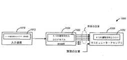
図8は、数学モデルの自由度よりも少ない自由度を有するような機械本体を制御するための簡略化システム800を示すブロック図である。システム800は、情報ソース810と、運動学モデル822を有する運動学プロセッサ820と、1つ以上のアクチュエータ830と、機械本体840とを含む。
FIG. 8 is a block diagram illustrating a
情報ソース810は、機械本体の位置を制御するための制御情報812の適切な情報源とすることができる。一実施形態では、情報ソース810は、外科医コンソール16(図1)、入力制御装置36(図2)及び/又はマスター制御入力装置700(図7A〜図7C)等の入力装置である。このような実施形態では、制御情報812は、N個の自由度を有する機械本体の所望の位置とすることができる。一実施形態では、N個の自由度は、機械本体の位置を完全に規定するのに必要な数の自由度であり、すなわち、独立して制御可能な3つの並進及び独立して制御可能な3つの回転である。従って、情報ソース810からの出力は、機械本体の位置を完全に制御するためのパラメータを含むことができる。一実施形態では、N個の自由度は、機械本体の位置を完全に規定するには不十分である。例えば、N個の自由度は、機械本体の3つの並進及び3つの回転の全てを独立して制御するには不十分である。従って、情報ソース810からの出力は、機械本体の位置を完全に制御するために不十分なパラメータを含むことがある。さらに別の実施形態では、N個の自由度は、機械本体の位置を規定しない(すなわち、非運動学的な自由度である)ような1つ以上の自由度を含んでもよい。例えば、N個の自由度は、真空圧を形成する等の器具を作動させるための1つ以上の自由度を含んでもよい。従って、情報ソース810からの出力は、機械本体の非運動学的な特性を制御するためのパラメータを含むことがある。これらは、真空圧による吸引に限定されるものではなく、追加的に又は代替的に、洗浄、通電(例えば、焼灼)、(例えば、単一のブレードやハサミ等の複数のブレードを使用する)切断、(例えば、はさみ、指等を使用する)把持を含む。
The
いくつかの実施形態では、情報ソース810が入力装置である場合に、入力装置自体が、N個の自由度を有しており、それによって、少なくともいくつかの例では、入力装置の各自由度は、機械本体の自由度に対応することができる。例えば、入力装置のロールは、機械本体の所望のロールに対応しており、或いは入力装置のピッチは、機械本体の所望のピッチに対応することができる。他の実施形態では、入力装置は、機械本体より多い又はより少ない数の自由度を有してもよい。例えば、入力装置は、1つ以上の冗長自由度を有することがあるのに対して、機械本体は、冗長自由度を有しないことがある。別の例では、機械本体は、1つ以上の冗長自由度を有することがあるのに対し、入力装置は、冗長自由度を有しないことがある。
In some embodiments, when the
入力装置は、N個の自由度を有する機械本体の所望の位置を示す出力を提供するが、入力装置によって制御される機械本体840は、機械本体の位置を完全に規定するために必要な自由度の少なくとも1つを欠いている。例えば、機械本体840は、ロール、ヨー及び/又はピッチの自由度を欠くことがあり、及び/又は、上/下、左/右、及び/又は前方/後方への並進自由度を欠くことがある。Nが、機械本体の位置を制御するための自由度の数を表す場合には、Mは、機械本体が欠いている、位置に関する自由度の数を表しており、次に一実施形態では、機械本体は、N−Mの自由度を有している。例えば、Nは6に等しく、機械本体の3つの全ての並進及び3つの全ての回転に対応しており、ここで、Mは、機械本体のロールに対応する1つの自由度を表す。もっとも、他の実施形態では、機械本体は、機械本体が冗長自由度を含む場合には、N個の自由度又はN個の自由度より多い自由度を有することができるが、依然として、機械本体の位置を完全に規定するのに必要な少なくとも1つの自由度を欠いている。
The input device provides an output indicating the desired position of the machine body with N degrees of freedom, but the
他の実施形態では、情報ソース810は、外科医コンソール等の入力装置ではなく、むしろツール位置測定装置である。この場合には、運動学的ブロック820は、制御装置ではなく、むしろ関節位置推定装置である。例えば、ツール位置測定装置は、ツールアセンブリ26の長さをツールアセンブリ26の自由端に延ばすような光ファイバや、マニピュレータ・アセンブリの関節に近接して配置された電磁センサ、又はマニピュレータ・アセンブリの関節の位置を測定するように作動可能である他のセンサ又は撮像装置を含むことができる。多くの実施形態では、ツール位置測定装置は、ツールの動きと干渉しないように、十分に小さく且つ軽量である。ツール位置測定装置が光ファイバを含む実施形態では、光ファイバの特性(例えば、屈折率)は、関節位置の変化の結果として変更される場合がある。光ファイバセンサのいくつかの例は、(2006年7月20日に出願された)Larkin等による”Robotic Surgery System Including Position Sensors Using Fiber Bragg Gratings”という標題の米国特許出願公開第2007/0156,019号明細書、及び(2008年6月30日に出願された)Giuseppe M. Priscoによる”Fiber optic shape sensor”という標題の米国特許出願第12/164,829号に記載されており、これら両文献は、全ての目的のためにその全体を参照することにより本明細書に組み込まれる。ツール位置測定装置は、次に、光ファイバの変更された特性に基づいて、ツールチップの位置(例えば、ツールアセンブリ26の自由端部)を決定するように作動可能である。ツール位置測定装置は、ツールの位置を多数の自由度で測定するようにさらに作動可能である。例えば、ツール位置測定装置は、ツールの1つ、2つ、又は3つの並進位置(例えば、x,y,zの位置)、及び/又はツールの1つ、2つ、又は3つの方向位置(例えば、ピッチ、ヨー、ロール)を測定することができる。少なくとも1つの実施形態では、ツール位置測定装置は、ツールの1つ以上の自由度の位置を測定するには作動不能となり得る。例えば、ツール位置測定装置が、光ファイバを含んでおり且つ光ファイバの特性の変化に基づいてチップ位置を推定する場合に、ツール位置測定装置は、ツールのロール運動を決定するのが困難になる。情報ソース810がツール位置測定装置である場合の実施形態では、制御情報812は、ツールチップの自由度の測定位置を示す測定情報とすることができる。
In other embodiments, the
いくつかの実施形態では、ツール位置測定装置は、マニピュレータ・アセンブリの自由度よりも少ない、等しい、又はより多い数のツールの複数の自由度の位置を測定するように作動可能である。多くの実施形態では、情報ソースが入力装置である場合について既に説明したように、機械本体は、機械本体の位置を完全に規定するために不十分であるN個の自由度を有しており、非運動学的な自由度を含んでもよく、冗長自由度等を含んでもよい。 In some embodiments, the tool position measurement device is operable to measure the positions of multiple degrees of freedom of a number of tools that are less than, equal to or greater than the degrees of freedom of the manipulator assembly. In many embodiments, the machine body has N degrees of freedom that is insufficient to fully define the position of the machine body, as already described for the case where the information source is an input device. Non-kinematic degrees of freedom may be included, and redundant degrees of freedom may be included.
情報ソース810からの出力は、情報ソース810が入力装置又はツール位置測定装置であるかに関係なく、運動学プロセッサ820においてN個の自由度の機械本体の運動学モデル822に適用される。運動学プロセッサ820は、外科医コンソール16、電子機器カート24、及び/又は患者側カート22等のMIRSシステム10(図1)の任意の適切な構成要素、ツールアセンブリ26、マニピュレータ・アセンブリ、及び/又は図7Aを参照して説明した制御システムに設けることができる。
The output from
情報ソース810が入力装置である場合の実施形態では、運動学モデル822は、所望の制御が入力装置から出力されるようなN個の自由度に対応するN個の自由度を有する機械本体のモデルとすることができる。例えば、入力装置は、機械本体の3つの並進及び3つの回転を制御するためのパラメータ等の、機械本体の位置を完全に制御するためのパラメータを出力することができる。運動学モデル822は、次に、3つの並進及び3つの回転を有する機械本体の運動学モデルとすることができる。いくつかの実施形態では、機械本体の位置を規定しないような1つ以上の自由度が、モデル化され、そうでなければ運動学モデル822とは別に制御することができる。それにも拘わらず、殆どの実施形態では、運動学モデル822は、機械本体840において1つ以上の自由度を欠いているような数学的表現を含む。例えば、機械本体840は、機械本体840のロールを制御するための自由度を欠いている。もっとも、運動学モデル822は、機械本体のロールを制御するための自由度を有する機械本体のモデルであってもよく、入力装置810は、機械本体のロールの所望の制御を示すような情報を出力することができる。
In an embodiment where the
情報ソース810がツール位置測定装置である場合の実施形態では、運動学モデル822は、関節の推定値(すなわち、機械本体840の自由度に対応する関節位置の推定値)が生成されるような機械本体のモデルとすることができる。例えば、ツール位置計測装置がN個の自由度の測定値のみを提供するような関節推定手法が使用される場合に、次に、運動学モデル822は、少なくともN個の自由度を有しており、機械本体は、(N−M)個の自由度等を有する。もっとも、他の実施形態では、機械本体は、N個の自由度より多い自由度を有してもよく、マニピュレータ・アセンブリは、複数の部品に論理的に分離することができ、ここで、各部品は、N個の関節又は運動学的な自由度だけを有するが、ツール位置測定装置は、各部品の端部の位置及び方向を測定するのに使用される。
In an embodiment where the
情報ソース810からの制御情報812を運動学プロセッサ820に適用した結果として、1つ以上の個々の制御出力824が、運動学プロセッサ820によって生成され、1つ以上のアクチュエータ830に伝達されて、機械本体840の1つ以上の自由度の制御に影響を及ぼすように作動可能になる。生成され且つアクチュエータ830に伝達された個々の制御出力824の数は、運動学プロセッサ820によって生成された個々の制御出力824の総数より少ない数である。つまり、アクチュエータ830に伝達された個々の制御出力824は、機械本体840が欠いている自由度(複数可)を制御するための情報を含んでいない。例えば、運動学モデル822は、機械本体の位置を完全に規定するための自由度を有する機械本体をモデル化することができ、これらの全ての自由度を制御するための出力を計算することができる。しかしながら、実際に制御される機械本体(すなわち、機械本体840)が、運動学モデル822によってモデル化された全ての自由度を有していない場合に、これらの計算された出力のサブセットのみが使用される。従って、アクチュエータ830に伝達された個々の制御出力824は、運動学モデル822を使用して生成される可能な指令のサブセットのみとなる。
As a result of applying
情報ソース810が入力装置である場合の実施形態では、個々の制御出力824は、機械本体840の自由度の所望の位置を示すような情報を含むことができる。例えば、個々の制御出力824は、機械本体840の1つの自由度に関連する関節の所望の位置(例えば、角度)を示すことができる。
In embodiments where the
情報ソース810がツール位置測定装置である場合の実施形態では、個々の制御出力824は、機械本体840の自由度の実際の位置を示すような情報を含むことができる。例えば、個々の制御出力824は、機械本体840の1つの自由度に関連する関節の実際の位置(例えば、角度)を示すことができる。
In embodiments where the
個々の制御出力824は、機械本体840の自由度の少なくともいくつかを制御するための1つ以上のアクチュエータ830によって受信される。例えば、アクチュエータ830は、例えば図5を参照して以前説明したように、機械本体840の関節を作動させるような電気モータ等とすることができる。一実施形態によれば、各アクチュエータは、機械本体840の対応する自由度を制御するように作動可能である。もっとも、他の実施形態では、1つのアクチュエータは、機械本体840の自由度より多い又はより少ない自由度を制御するように作動可能である。
機械本体840は、少なくとも1つの自由度を有する任意の適切な機械本体とすることができる。例えば、機械本体は、ロボット・マニピュレータアーム(例えば、図4を参照して説明したマニピュレータアーム100又は図5を参照して説明したマニピュレータアーム500)、及び/又は手術用器具(例えば、図1を参照して説明した器具26又は図5を参照して説明した機器511)とすることができる。いくつかの実施形態では、機械本体は、マニピュレータアームと手術用器具との両方の運動学的態様を含んでもよい。
The
前述したように、様々な実施形態は、入力装置であるような情報ソース810を組み込んでおり、それによって、運動学プロセッサ820は、機械本体840の関節の所望の位置を出力する。他の実施形態は、ツール位置測定装置であるような情報ソース810を組み込んでおり、それによって、運動学プロセッサ820は、機械本体840の関節の実際の位置を出力する。さらに他の実施形態では、システムは、入力装置とツール位置測定装置とを両方とも含んでおり、この入力装置は、運動学モデル及びこの入力装置に特有の制御装置(すなわち、運動学プロセッサの一種)に所望の位置を提供しており、このツール位置測定装置は、運動学モデル及びこのツール位置測定装置に特有の推定装置(すなわち、運動学プロセッサの一種)にツールチップ位置情報を提供する。このような場合に、ツールチップ位置測定装置によって使用される運動学モデルは、入力装置によって使用される運動学モデルとは異なっていてもよい。さらに、各運動学モデルの出力、すなわち、マニピュレータ・アセンブリの関節の所望の位置及び実際の位置は、各関節モータに適用される実際のトルク量を計算するために一緒に使用されることがある。ツール位置測定装置が設けられていない場合の実施形態では、システムは、推定された関節位置を取得して、入力装置を使用してトルク量を生成するときに、これら関節位置を所望の位置出力に結び付けることができる。これらの更なる実施形態のいくつかは、図9を参照して説明する。
As described above, various embodiments incorporate an
特定の実施形態における800システムは、機械本体を制御するための簡略化されたシステムであり、入力装置810、運動学プロセッサ820、アクチュエータ(複数可)830、及び機械本体840等の様々な構成要素を含む。もっとも、当業者によって理解されるように、システムは、図8に示されるよりも少ない又はより多い数の構成要素を有することにより、同様に良好に操作することができる。従って、図8に示されるシステム800は、本質的に例示として捉えるべきであり、本開示の範囲を制限するものではないことに注意する必要がある。
The 800 system in certain embodiments is a simplified system for controlling a machine body and includes various components such as an
図9は、一実施形態によるアクチュエータ830のブロック図である。アクチュエータ830は、関節制御装置832と、モータ834とを含んでおり、ここで、関節制御装置832は、モータ834を制御するためのトルクコマンド836を生成するように作動可能にされる。モータ834は、マニピュレータ・アセンブリの自由度を制御するためにマニピュレータ・アセンブリの1つ以上の関節に結合される。この実施形態では、アクチュエータ830は、自由度(X)を制御するように作動可能である。
FIG. 9 is a block diagram of an
トルクコマンド836を生成するために、関節制御装置834は、自由度(X)の所望の位置824Aを受信する。所望の位置は、外科医コンソール等の入力装置から受信することができる。例えば、所望の位置824は、情報ソース810が入力装置である場合に、運動学プロセッサ820(図8)によって生成することができる。従って、所望の位置824Aは、入力装置から伝達された制御情報を運動学モデル822に適用するとともに、個々の制御出力824のサブセットのうちの1つのみを所望の位置824Aとして使用することによって、生成することができる。
To generate the
トルクコマンド836を生成するために、関節制御装置834は、自由度(X)の実際の位置824Bを受信する。実際の位置は、多数の技術のうちの1つ以上を使用して生成することができる。一実施形態では、実際の位置は、各関節のモータに使用されるエンコーダに基づいて決定することができる。他の実施形態では、実際の位置は、マニピュレータ・アセンブリの端部(例えば、ツールチップ)の位置(例えば、位置及び/又は向き)、及び逆運動学を適用することにより計算することができる。マニピュレータ・アセンブリの端部の位置を感知するためのセンサ装置は、ツールチップに一端が固定された状態でマニピュレータ・アセンブリの長さに沿って配置された光ファイバを含んでおり、そして、関節位置の変化により、光ファイバの特性(例えば、屈折率)に変化が生じる。別の実施形態では、センサ装置は、マニピュレータ・アセンブリの終点(エンドポイント)に取り付けられた1つ以上の電磁センサを含んでおり、それによって、チップ位置での任意の変化を、電磁場発生器により測定することができる。例えば、図8を参照して、情報ソース810は、ツールチップ位置を決定するように作動可能な感知装置であり、ツールチップ測定位置を運動学モデル822に適用することによって、個々の制御出力824のサブセットの1つが、実際の位置824Bとして使用される。
To generate the
DOF(X)の所望の位置と実際の位置との両方を受信すると、関節制御装置832は、その実際の(すなわち、現在の)位置から所望の位置に移動させるような自由度を有するようにモータトルクの適切な量を決定することができる。関節制御装置832は、次に、このトルク量を示すトルクコマンド836をモータ834に送信する。
Upon receiving both the desired position and the actual position of DOF (X), the
図10Aは、第1の実施形態による入力装置を用いて、マニピュレータ・アセンブリを制御するための簡略化したシステムを示すブロック図である。システム1000は、入力装置1010と、制御装置1020と、マニピュレータ・アセンブリ1030とを含む。入力装置1010は、図8を参照して説明した情報ソース810と同様のものとすることができ、制御装置1020は、図8を参照して説明した運動学プロセッサ820と同様のものとすることができ、マニピュレータ・アセンブリ1030は、図8を参照して説明したアクチュエータ及び機械本体840と同様のものとすることができる。一実施形態では、マニピュレータ・アセンブリ1030は、マニピュレータ(例えば、マニピュレータ500)及び/又はツール(例えば、ツール511)を含む。マニピュレータ・アセンブリ1030は、マニピュレータの1つ以上の運動学的な自由度を有しており、いくつかの実施形態では、追加的に又は代替的に、1つ以上の作動自由度を有している。さらに、マニピュレータ・アセンブリ1030は、1つ以上のエンドエフェクタ(すなわち、より一般的には、制御フレーム)の位置を制御するように作動可能である。例えば、エンドエフェクタは、マニピュレータ・アセンブリ1030の一部であるツールのチップや、ツール等のシャフトの途中までに、規定することができる。エンドエフェクタは、マニピュレータの自由度と同じ又は異なる数の自由度を有する。
FIG. 10A is a block diagram illustrating a simplified system for controlling a manipulator assembly using the input device according to the first embodiment.
図10Aに示した実施形態によれば、入力装置1010及び制御装置1020は、マニピュレータ・アセンブリ1030が実際に有するよりも多い数のマニピュレータの運動学的な自由度(すなわち、マニピュレータ・アセンブリ1030の自由度)を制御するように作動可能である。例えば、入力装置1010は、独立して制御可能な3つの回転自由度と独立して制御可能な3つの並進自由度とを含むような6つの運動学的な自由度1012を有している。入力装置1010は、入力装置1010の位置に対応するような、又はそうでなければマニピュレータ・アセンブリ1030に関連するエンドエフェクタの所望の位置を示すようなパラメータ又は他の情報を出力する。
In accordance with the embodiment shown in FIG. 10A, the
入力装置1010からの出力は、制御装置1020によって受信され且つ処理されて、マニピュレータ・アセンブリ1030を制御するための指令(例えば、マニピュレータ・アセンブリ1030の関節に関連するモータを制御するための指令)を提供する。この実施形態では、制御装置1020は、エンドエフェクタの独立して制御可能な3つの回転自由度及び独立して制御可能な3つの並進自由度を制御するための、6つの運動学的な自由度を有するマニピュレータ・アセンブリの運動学モデル1022を含む。
Output from the
入力装置1010からの出力を運動学モデル1022に適用することにより得られる結果のサブセットは、次に、マニピュレータ・アセンブリ1030を制御するために使用される。例えば、この結果のサブセットは、マニピュレータ・アセンブリ1030の関節に関連する1つ以上のアクチュエータに伝達される。この実施形態におけるマニピュレータ・アセンブリ1030は、4つの運動学的な自由運度を有する。マニピュレータ・アセンブリ1030は、こうして、2つの運動学的な自由度を欠いている。例えば、マニピュレータ・アセンブリ1030は、ヨー及びピッチ運動に対応する自由度を欠いており、又は2つの並進運動に対応する自由度を欠いていることがある。従って、サブセットは、マニピュレータ・アセンブリ1030の構成に使用されるようなこれらの自由度のみを制御するための指令を含む。この場合に、指令は、マニピュレータ・アセンブリ1030の関節の所望の位置を示すものであり、マニピュレータ・アセンブリ1030の関節の実際の位置を示す情報と組み合わせることができる。この組合せを使用して、適切なトルクを決定し、関節モータに適用することができる。
The subset of results obtained by applying the output from
他の実施形態では、入力装置及び運動学モデルは、6つの運動学的な自由度を有してない場合があり、エンドエフェクタは、4つの運動学的な自由度を有していない場合がある。むしろ、入力装置及び運動学モデルは、マニピュレータ・アセンブリに配備されるよりも多い数の自由度を制御するように構成することができる。例えば、入力装置1010及び制御装置1020は、5つの運動学的な自由度を制御するように構成することができるのに対し、マニピュレータ・アセンブリは、1〜4の運動学的な自由度を有することができる。
In other embodiments, the input device and kinematic model may not have six kinematic degrees of freedom and the end effector may not have four kinematic degrees of freedom. is there. Rather, the input device and kinematic model can be configured to control a greater number of degrees of freedom than deployed in the manipulator assembly. For example, the
図10Bは、第2の実施形態による入力装置を使用して、マニピュレータ・アセンブリを制御するための簡略化したシステム1001を示すブロック図である。システム1001は、図10Aを参照して説明したのと同様の、入力装置1010と、制御装置1020と、マニピュレータ・アセンブリ1030とを含む。
FIG. 10B is a block diagram illustrating a
この実施形態によれば、入力装置1010及び制御装置1020は、図10Aを参照して説明した実施形態と同様に、マニピュレータ・アセンブリ1030が有するよりも多い数の運動学的な自由度を制御するように作動可能である。さらに、入力装置1010は、マニピュレータ・アセンブリ1030の非運動学的な自由度を作動させことができる。例えば、入力装置1010は、マニピュレータ・アセンブリ1030に関連する真空圧力を作動させることができる。
According to this embodiment, the
従って、この実施形態では、入力装置1010は、6つの運動学的な自由度1012だけでなく、少なくとも1つの作動自由度1014を含んでおり、ここで、作動自由度は、非運動学的な自由度を意味する。一実施形態では、作動自由度は、1つ以上の把持部材723(図7B)等の入力装置1010上の要素を介して作動させることができる。入力装置1010は、6つの運動学的な自由度を介して、次に、入力装置1010の位置に対応するような、又はそうでなければマニピュレータ・アセンブリ1030に関連するエンドエフェクタの所望の位置を示すようなパラメータ又は他の情報を出力する。また、入力装置1010は、1つの作動自由度を介して、マニピュレータ・アセンブリ1030、或いはマニピュレータ・アセンブリ1030に又はこのアセンブリ1030の一部に結合されたツールの機能(例えば、真空装置、1つ以上のはさみ/指等を作動させる)を作動させるためのパラメータ又は他の情報を出力することができる。
Thus, in this embodiment, the
入力装置1010からの出力は、制御装置1020によって受信され且つ処理されて、マニピュレータ・アセンブリ1030を制御するための指令を提供する。この実施形態では、制御装置1020は、図10Aを参照して説明したのと同様の、6つの運動学的な自由度を有するようなマニピュレータ・アセンブリの運動学モデル1022を含む。さらに、制御装置1020は、作動自由度1014に関する入力装置1010からの出力を処理するとともに、この出力を使用してマニピュレータ・アセンブリ1030の機能を作動させることができるような作動制御装置1024も含む。
Output from
入力装置1010からの出力を運動学モデル1022に適用することにより得られた結果のサブセットは、次に、図10Aを参照して説明したのと同様に、マニピュレータ・アセンブリ1030を制御するために使用される。さらに、入力装置1010からの作動出力を作動制御装置1024に適用することにより得られる結果は、マニピュレータ・アセンブリ1030の作動(マニピュレータ・アセンブリ1030に又はこのアセンブリ1030の一部に結合されたツールの作動)を制御するために使用することができる。図10Aを参照して説明したように、他の実施形態では、入力装置及び運動学モデルは、6つの運動学的な自由度を有していない場合があり、エンドエフェクタは、4つの運動学的な自由度を有していない場合がある。さらに、いくつかの実施形態では、入力装置1010は、複数の作動自由度を含んでもよく、作動制御装置1024は、入力装置1010からの複数の作動自由度についての出力を処理するように作動可能であり、マニピュレータ・アセンブリ1030は、マニピュレータ・アセンブリ1030の制御とは別に、入力装置1010によって制御されるような対応する数の作動自由度を有してもよい。
The subset of results obtained by applying the output from the
図10Cは、第3の実施形態による入力装置を使用して、マニピュレータ・アセンブリを制御するための簡略化したシステム1002を示すブロック図である。システム1002は、図10Aを参照して説明したものと同様の、入力装置1010と、制御装置1020と、マニピュレータ・アセンブリ1030とを含む。
FIG. 10C is a block diagram illustrating a
この実施形態によれば、マニピュレータ・アセンブリ1030は、少なくとも1つのゼロ空間の自由度(例えば、3つのゼロ空間の自由度)を含むような多数の運動学的な自由度(例えば、8)を有しているが、依然としてマニピュレータ・アセンブリ1030に関連するエンドエフェクタの位置を完全に規定するために必要な自由度のうちの少なくとも1つを欠いている。例えば、マニピュレータ・アセンブリ1030は、冗長自由度を含む8つの運動学的な自由度を含んでいるが、依然として、少なくとも1つの独立して制御可能な回転自由度又は並進自由度を欠いている。
According to this embodiment, the
なお、マニピュレータ・アセンブリのゼロ空間の自由度が本明細書で説明される場合に、制御フレームは、マニピュレータ・アセンブリ上に位置している(例えば、制御フレームは、ツールチップに位置している)と想定されることを認識すべきである。もっとも、実施形態は、このようなケースに限定されるものではなく、こうして、マニピュレータ・アセンブリのゼロ空間の自由度が説明される場合に、実施形態は、代替的に、ヤコビアンのゼロ空間の自由度を含む。ここで、ヤコビアンは、患者の組織や、ツールチップから一定距離等での、適宜に規定される位置を有するマニピュレータ・アセンブリ及び制御フレームに関連している。 It should be noted that the control frame is positioned on the manipulator assembly when the zero space degrees of freedom of the manipulator assembly are described herein (eg, the control frame is positioned on the tooltip). It should be recognized that However, the embodiment is not limited to such a case, and thus, if the zero-space freedom of the manipulator assembly is described, the embodiment may alternatively be a Jacobian zero-space freedom. Including degrees. Here, the Jacobian is associated with a manipulator assembly and a control frame having appropriately defined positions, such as a certain distance from the patient's tissue and tooltip.
入力装置1010は、図10Aを参照して説明したものと同様に、6つの運動学的な自由度1012を含む。制御装置1020は、次に、入力装置1010からの出力を9つの運動学的な自由度を含む運動学モデル1026に適用することにより、入力装置1010からの出力を処理するように作動可能であり、この9つの運動学的な自由度は、図10Aを参照して説明したような6つの運動学的な自由度だけでなく、3つのゼロ空間の自由度を含む。こうして、制御装置1020は、マニピュレータ・アセンブリ1030が、9つの運動学的な自由度を含む(その内、3つのゼロ空間の自由度を含む)ような仮定で出力を生成することができる。もっとも、マニピュレータ・アセンブリ1030は、8つの運動学的な自由度のみを有しているので、制御装置1020は、マニピュレータ・アセンブリ1030の欠落している運動学的な自由度に対応する出力を提供しない。むしろ、制御装置1020は、マニピュレータ・アセンブリ1030の8つの運動学的な自由度を制御するための指令を出力する。
図10Dは、第4の実施形態による入力装置を使用して、マニピュレータ・アセンブリを制御するための簡略化したシステム1003を示すブロック図である。システム1003は、図10Aを参照して説明したものと同様の、入力装置1010と、制御装置1020と、マニピュレータ・アセンブリ1030とを含む。
FIG. 10D is a block diagram illustrating a
この実施形態によれば、入力装置1010は、1つ以上のゼロ空間の自由度を含んでいるのに対して、マニピュレータ・アセンブリ1030は、ゼロ空間の自由度を何ら含んでおらず、入力装置1010よりも少ない運動学的な自由度を含んでいる。他の実施形態では、マニピュレータ・アセンブリ1030は、入力装置1010と同じ又はより多い数のゼロ空間の自由度を含んでもよい。
According to this embodiment, the
従って、この実施形態では、入力装置1010は、7つの運動学的な自由度1016を含む(その内、1つのゼロ空間の自由度を含む)ような多数の自由度を含む。入力装置1010からの出力は、次に、処理され、最終的に制御装置1020に供給され、ここで、制御装置1020は、5つの自由度を有するマニピュレータ・アセンブリの運動学モデルを含むことができる。制御装置1020は、次に、入力装置1010からの出力を運動学モデル1028に適用し、次に、図10Aを参照して説明したのと同様に、この結果のサブセットを使用して、マニピュレータ・アセンブリ1030を制御することができる。
Thus, in this embodiment,
この実施形態では、マニピュレータ・アセンブリ1030は、4つの運動学的な自由度1032を含む。もっとも、他の実施形態では、マニピュレータ・アセンブリ1030は、4つの運動学的な自由度よりも少ない自由度を含んでもよい。また、入力装置1010が、1つのゼロ空間の自由度を有するものとして説明される限り、入力装置1010は、複数のゼロ空間の自由度を有してもよい。例えば、入力装置1010は、2つ、3つ、又は4つのゼロ空間の自由度を有してもよい。
In this embodiment,
特定の実施形態におけるシステム1000,1001,1002,1003は、入力装置を使用してエンドエフェクタを制御するための簡略化されたシステムであり、入力装置1010、制御装置1020、及びマニピュレータ・アセンブリ1030等の様々な構成要素を含む。しかしながら、当業者によって理解されるように、これらのシステムは、図10A〜図10Dに示されるよりも少ない又はより多い数の構成要素を有することにより、同様に良好に操作することができる。例えば、いくつかの実施形態では、入力装置は、1つ以上の運動学的な自由度に加えて、ゼロ空間の自由度と作動自由度との両方を有してもよく、制御装置は、ゼロ空間の自由度と作動制御装置との両方を有してもよく、マニピュレータ・アセンブリは、ゼロ空間の自由度と作動自由度との両方を有してもよい。従って、図10A〜図10Dに示されるシステムは、本質的に例示として捉えるべきであり、本開示の範囲を制限するものではないことに注意する必要がある。
The
図11Aは、第1の実施形態によるツール位置測定装置を使用して、マニピュレータ・アセンブリを制御するための簡略化したシステム1100を示すブロック図である。システム1100は、ツール位置測定装置1110と、関節推定装置1120と、マニピュレータ・アセンブリ1130とを含む。
FIG. 11A is a block diagram illustrating a
システム1100の要素は、ツール位置測定装置1110が入力装置1010の代わりに設けられており、且つ関節推定装置1120が制御装置の代わりに設けらていることを除いて、システム1000の同様にラベル付けされた要素と同様である。従って、システム1000に関する説明は、制御装置が、所望の位置情報を受信し且つ適用する代わりに、関節推定装置が、位置測定情報受信し且つ適用するようなシステム1100の場合を除いて、システム1100に同様に適用可能である。そして、所望の位置を生成する代わりに、関節推定装置1120は、マニピュレータ・アセンブリの関節の実際の位置(例えば、関節角度)を生成する。いくつかの実施形態では、実際の位置は、マニピュレータ・アセンブリ1130の関節の所望の位置を示すような情報と組み合わせることができる。この組合せを使用し、適切なトルクを決定して関節モータに適用することができる。
Elements of the
また、ツール位置測定装置1100は、5つ以下のみの自由度を測定することができる。この特定の実施形態では、ツール位置測定装置1100は、5つの自由度を測定するように示されるが、もっとも、そのツール位置測定装置は、同様に、4つの自由度、3つの自由度、又は3つ未満の自由度も測定し得る。そして、関節推定装置1120は、5つの関節位置のみを生成するような5つの自由度の運動学モデル1122のみを使用する、ここで、5つの自由度のうちの4つが使用される(これら4つの自由度は、マニピュレータ・アセンブリ1130の実際の関節に対応する)が、1つは廃棄される(マニピュレータ・アセンブリ1130に対応する関節が存在しない)。いくつかの実施形態では、2つの関節推定値がその後廃棄されるような6つのDOFの運動学モデル1122が、使用され、すなわち、5つ未満の運動学的なDOFが使用される。
Moreover, the tool
図11Bは、第2の実施形態によるツール位置測定装置を使用して、マニピュレータ・アセンブリを制御するための簡略化したシステム1102を示すブロック図である。システム1102は、ツール位置測定装置1110と、関節推定装置1120と、マニピュレータ・アセンブリ1130とを含む。
FIG. 11B is a block diagram illustrating a
システム1102の要素は、ツール位置測定装置1110が入力装置1010の代わりに設けられており、且つ関節推定装置1120が制御装置の代わりに設けられていることを除いて、システム1002の同様にラベル付けされた要素と同様である。従って、システム1002に関する説明は、制御装置が、所望の位置情報を受信し且つ適用する代わりに、関節推定装置が、位置測定情報受信し且つ適用するようなシステム1102の場合を除いて、システム1102に同様に適用可能である。そして、所望の位置を生成する代わりに、関節推定装置1120は、マニピュレータ・アセンブリの関節の実際の位置(例えば、関節角度)を生成する。いくつかの実施形態では、実際の位置は、マニピュレータ・アセンブリ1130の関節の所望の位置を示すような情報と組み合わせることができる。この組合せを使用し、適切なトルクを決定して関節モータに適用することができる。
Elements of
さらに、この特定の実施形態では、マニピュレータ・アセンブリは、複数のピッチ及びヨー関節を含むような8つの運動学的な自由度を有するものとして示されている。マニピュレータ・アセンブリのいくつかの実施形態では、マニピュレータ・アセンブリは、複数の部品に論理的に分離することができる。光ファイバが各部品の端部において位置及び向きを測定するために使用されるような実施形態では、各部品は、ツール位置測定装置1112(a),1112(b)が5つの自由度を測定する際に、5つ以下の関節の自由度を有する。これら部品は、それぞれ同じ又は異なる数の自由度を有する。例えば、この実施形態では、マニピュレータ・アセンブリは、2つの部品に論理的に分離され、それぞれの部品が、4つの自由度を有する。 Further, in this particular embodiment, the manipulator assembly is shown as having eight kinematic degrees of freedom including multiple pitch and yaw joints. In some embodiments of the manipulator assembly, the manipulator assembly can be logically separated into multiple parts. In an embodiment where an optical fiber is used to measure position and orientation at the end of each part, each part has a tool position measuring device 1112 (a), 1112 (b) measuring five degrees of freedom. In doing so, it has 5 or less joint degrees of freedom. Each of these parts has the same or different number of degrees of freedom. For example, in this embodiment, the manipulator assembly is logically separated into two parts, each part having four degrees of freedom.
少なくとも1つの実施形態では、各部品の関節の数は、関節を他の部品に組み込む前に最大化してもよい。例えば、7つの自由度を有するマニピュレータ・アセンブリについて、1つの部品が、5つの自由度(すなわち、最大数)を有してもよく、別の部品が、残りの自由度、すなわち2つの自由度を有してもよい。別の例では、12個の自由度を有するマニピュレータ・アセンブリについて、2つの部品は、それぞれ5つの自由度を有しているが、3つめの部品は、2つの自由度のみを有している。いくつかの例では、1つ以上の部品についての関節角度は、計算がより効率的である場合に、逆運動学よりもむしろ幾何学を使用して計算してもよい。例えば、2以下の数の自由度を有する部品について関節推定値を計算する場合に、逆運動学よりも幾何学を使用して、より効率的に計算してもよい。 In at least one embodiment, the number of joints in each part may be maximized before the joint is incorporated into other parts. For example, for a manipulator assembly having seven degrees of freedom, one part may have five degrees of freedom (ie, the maximum number) and another part has the remaining degrees of freedom, ie two degrees of freedom. You may have. In another example, for a manipulator assembly having 12 degrees of freedom, each of the two parts has 5 degrees of freedom, while the third part has only 2 degrees of freedom. . In some examples, the joint angles for one or more parts may be calculated using geometry rather than inverse kinematics if the calculation is more efficient. For example, when calculating joint estimates for a part having a number of degrees of freedom of 2 or less, it may be calculated more efficiently using geometry than inverse kinematics.
ツール位置測定装置1110は、マニピュレータ・アセンブリの各論理的な部品についての位置を測定するように作動可能である。例えば、ツール位置測定装置1110は、第1の部品のチップ位置と第2の部品のチップ位置とを測定することができる。各部品のチップ位置は、同じ又は異なる数の自由度として測定され、ここで、測定された自由度は、対応する部品の自由度より小さい、同じ、又はより多い自由度とすることができる。この特定の例では、第1の部品のチップ位置は、5つの自由度1112(a)で測定され、第2の部品のチップ位置は、同様に、5つの自由度1112(b)で測定される。これらの自由度は、必ずしも同じである必要はなく、いくつかの実施形態では、5未満の数であってもよいことを認識されたい。
Tool
関節推定装置1120は、次に、マニピュレータ・アセンブリの各論理的な部品の運動学モデルを含んでもよい。この実施形態では、関節推定装置1120は、第1の運動学モデル1126(a)と、第2の運動学モデル1126(b)とを含む。第1の運動学モデル1126(a)は、マニピュレータ・アセンブリ1130の第1の部品の運動学モデルであり、第2の運動学モデル1126(b)は、マニピュレータ・アセンブリ1130の第2の部品の運動学モデルである。各運動学モデルは、それぞれのマニピュレータ・アセンブリ部品に対応するチップ測定からの出力を受け取る。例えば、第1の測定1112(a)の出力は、第1の運動学モデル1126(a)に適用され、第2の測定1112(b)の出力は、第2の運動学モデル1126(b)に適用される。第1の運動学モデル1126(a)は、次に、マニピュレータ・アセンブリ1130の第1の部品の実際の位置を出力するのに対して、第2の運動学モデル1126(b)は、マニピュレータ・アセンブリ1130の第2の部品の実際の位置を出力する。
The
運動学モデル1126(a),1126(b)のうちの少なくとも1つの自由度は、対応するマニピュレータ・アセンブリ部品の自由度の実際の数よりも多くすることができることは明らかである。この特定の実施形態では、必ずしも必要ではないが、両方の運動学モデルは、それら対応するマニピュレータ・アセンブリ部品より多い数の自由度を有している。すなわち、第1の運動学モデル1126(a)は、5つの自由度を有するのに対して、マニピュレータ・アセンブリ1130の第1の部品は、4つの自由度のみを有する、及び同様のことが当てはまり、第2の運動学モデル1126(b)は、5つの自由度を有するのに対して、マニピュレータ・アセンブリ1130の第2の部品は、4つの自由度のみを有する。この余分な自由度を使用して出力が生成されるが、本明細書で説明した他の余分な運動学モデルの自由度と同様に、その後、マニピュレータ・アセンブリ部品の実際の位置を決定するために使用されない。
Obviously, the degree of freedom of at least one of the kinematic models 1126 (a), 1126 (b) can be greater than the actual number of degrees of freedom of the corresponding manipulator assembly part. In this particular embodiment, although not necessary, both kinematic models have a greater number of degrees of freedom than their corresponding manipulator assembly parts. That is, the first kinematic model 1126 (a) has five degrees of freedom, whereas the first part of the
図11A及び図11Bを参照して説明したシステムは、説明目的のために同様であると考慮され、図10A〜図10Dを参照して説明した実施形態は、マニピュレータ・アセンブリの関節の所望の位置を生成するためのシステムを対象としているのに対して、図11A及び図11Bを参照して説明した実施形態は、マニピュレータ・アセンブリの関節の実際の位置を生成するためのシステムを対象としていることを認識されたい。いくつかの実施形態では、既に説明したように、これらのシステムは、1つのシステムに組み合わせてもよい。例えば、図10A〜図10Dの入力装置及び制御装置は、所望の位置を生成するために使用することができ、図11A及び図11Bのツール位置測定装置及び関節推定装置は、実際の位置を生成するために使用されることができ、これらの生成された位置は、図9を参照して説明したように組み合わせて使用することができる。 The system described with reference to FIGS. 11A and 11B is considered to be similar for illustrative purposes, and the embodiment described with reference to FIGS. 10A-10D may provide the desired position of the joint of the manipulator assembly. 11A and 11B, the embodiment described with reference to FIGS. 11A and 11B is directed to a system for generating the actual position of a joint of a manipulator assembly. I want to be recognized. In some embodiments, as previously described, these systems may be combined into one system. For example, the input device and the control device in FIGS. 10A to 10D can be used to generate a desired position, and the tool position measurement device and the joint estimation device in FIGS. 11A and 11B generate an actual position. These generated locations can be used in combination as described with reference to FIG.
図12Aは、一実施形態によるマニピュレータ・アセンブリ1200である。マニピュレータ・アセンブリ1200は、図11Bを参照して説明したマニピュレータ・アセンブリ1130と同様である。マニピュレータ・アセンブリ1200は、多数のリンク1202と多数の関節1204とを含む。マニピュレータ・アセンブリ1200は、第1の部分1206と第2の部分1208とに論理的に分離される。第1の部分1206は、マニピュレータ・アセンブリのある点(ポイント)から、つまりマニピュレータ・アセンブリの自由端から最も離れた箇所から延びており、それはベース1210として規定される。第1の部分1206は、ベース1210から第1の部品1212のチップ位置として同定されるようなマニピュレータ・アセンブリ内のポイントに延びる。第2の部分1208は、次に、第1の部品1212のチップ位置から第2の部品1214のチップ位置として規定されるポイントに延びており、この実施例では、マニピュレータ・アセンブリ1200の自由端に位置する。
FIG. 12A is a
多数の関接が、第1の部分1206内に配置されており、多数の別の関節が、第2の部分1208内に配置されている。この数は同じでなくてもよいが、この例では、第1及び第2の部分のそれぞれは、4つの関節を含む。他の実施例では、関節の総数が8つである場合に、第1及び第2の部分は、それぞれ、5つ及び3つの、又は3つ及び5つの関節を含んでもよい。5つより多くの関節を有するマニピュレータ・アセンブリについての他の様々な組合せを実現することもできる。さらに、マニピュレータ・アセンブリは、2つより多くの部分に論理的に分離してもよい。例えば、関節の総数が8つである場合には、第1の部分は、5つの関節を有しており、第2の部分は、2つの関節を有しており、第3の部分は、1つの関節を有する。殆どの実施形態では、ツール位置測定装置がN個の自由度の測定値のみを提供するような関節推定手法が用いられる場合に、次に、各部分はN個以下の関節又は自由度を含む。さらに、マニピュレータ・アセンブリがN個より多くの運学的な自由度を含む場合に、これらの自由度は、複数の論理的な部分に分離される。一実施形態では、ロール方向の推定が利用できないような光ファイバーアプローチが使用される場合に、次に、各部分は、5つ以下の関節又は運動学的な自由度を含むことになる。
A number of articulations are disposed in the
図12Bについて簡潔に説明すると、図12Bには、一実施形態による複数のマニピュレータ・アセンブリ部品の関節位置の計算を示すようなブロック図1250が示されている。この例における関節推定装置1252は、第1の運動学モデル1254と第2の運動学モデル1256とを含む。第1の運動学モデル1254は、マニピュレータ・アセンブリの第1のセグメント又は部分の運動学モデルである。例えば、これは、第1の部分1206の運動学モデルである。第2の運動学モデル1256は、マニピュレータ・アセンブリの第2のセグメント又は部分の運動学モデルである。例えば、これは、第2の部分1208の運動学モデルである。
Turning briefly to FIG. 12B, a block diagram 1250 is shown in FIG. 12B that illustrates the calculation of joint positions of a plurality of manipulator assembly parts according to one embodiment. The
各運動学モデルは、ファントム(phantom)自由度を含む。つまり、マニピュレータ・アセンブリの対応する部分には存在しないような自由度を含む。例えば、図12Aに示される実施形態では、光ファイバーアプローチを使用するときに、ロール方向の推定値が利用できないが、各運動学モデルは、ファントムのロール自由度を含むことができる。もっとも、他の実施形態では、1つ以上の運動学モデルは、複数のファントムの自由度を含んでもよい。いくつかの実施形態では、1つの運動学モデルのみが、ファントム自由度を含む。 Each kinematic model includes phantom degrees of freedom. That is, it includes a degree of freedom that does not exist in the corresponding part of the manipulator assembly. For example, in the embodiment shown in FIG. 12A, when using a fiber optic approach, no estimate of roll direction is available, but each kinematic model can include phantom roll degrees of freedom. However, in other embodiments, the one or more kinematic models may include multiple phantom degrees of freedom. In some embodiments, only one kinematic model includes phantom degrees of freedom.
第1のセグメントのチップ位置が、第1の運動学モデル1254に入力される。例えば、チップ位置1212が、第1の運動学モデル1254に入力される。第1の運動学モデル1254からの出力は、第1セグメント1206の関節位置(だけでなく、無視される、ファントム自由度に対応する出力の1セット)である。第1のセグメントのチップ位置(例えば、チップ位置1212)と、第2のセグメントのチップ位置(例えば、チップ位置1214)との間の差が、第2の運動学モデル1256に入力される。第2の運動学モデル1256からの出力は、第2のセグメント1208の関節位置(だけでなく、無視される、ファントム自由度に対応する出力の1セット)である。
The tip position of the first segment is input to the first
図13は、第1の実施形態による入力装置を用いて、マニピュレータアーム、ツール、及び/又はエンドエフェクタを制御するためのプロセス1300を示すようなフローチャートである。マニピュレータアーム、ツール、及び/又はエンドエフェクタは、本明細書で説明するもののいずれでもよく、例えば、マニピュレータアーム100(図4)、マニピュレータアーム500(図5)、ツール26(図1A)、手術用ツール600(図6A)、内視鏡620(図6B)、オーバーチューブ630(図6C)、アクチュエータ830及び/又は機械本体840(図8)等である。入力装置は、本明細書で説明する入力装置のいずれでもよく、例えば、入力装置36(図2)、入力装置700(図7A〜図7C)、入力装置810(図8)等である。さらに、プロセス1000は、本明細書で説明する制御装置のいずれかによって行うことができ、例えば、図7Aを参照して説明した制御システム、運動学プロセッサ820(図8)、及び/又は、外科医コンソール16、電子機器カート24、及び/又は患者側カート22等のMIRSシステム10(図1)の適切な構成要素に設けられた任意の他の適切な制御装置である。
FIG. 13 is a flowchart illustrating a
1つの特定の実施形態では、マニピュレータ・アセンブリの運動学的な自由度は、システムのモータを使用して制御装置により1つ以上の関節を駆動することによって制御され、関節は、制御装置のプロセッサによって計算され、調整された関節運動に従って駆動される。数学的には、制御装置は、ベクトル及び/又は行列を使用して関節コマンドの計算の少なくとも一部を実行することができ、そのうちのいくつかは、関節の構成又は速度に対応する成分を有することができる。プロセッサについて利用可能な代替の関節構成の範囲は、関節空間として概念化することができる。例えば、関節空間は、マニピュレータ・アセンブリが有する自由度と同じ、多くの次元を有することができ、いくつかの例示的実施形態では、関節空間は、マニピュレータ・アセンブリが、マニピュレータ・アセンブリに関連するエンドエフェクタの位置を完全に規定するために必要な少なくとも1つの自由度を欠いている場合に、マニピュレータ・アセンブリが有する自由度より多くの次元を有することができる。さらに、マニピュレータ・アセンブリの特定の構成は、関節空間内の特定の点を表すことができ、各座標は、マニピュレータの関連する関節が存在する場合に、マニピュレータ・アセンブリの関連する関節の関節状態に対応する。 In one particular embodiment, the kinematic freedom of the manipulator assembly is controlled by driving one or more joints with the controller using the motor of the system, the joints being the processor of the controller. And is driven according to the adjusted joint motion. Mathematically, the controller can perform at least part of the calculation of joint commands using vectors and / or matrices, some of which have components corresponding to the joint configuration or velocity be able to. The range of alternative joint configurations available for the processor can be conceptualized as joint space. For example, the joint space can have as many dimensions as the degrees of freedom that the manipulator assembly has, and in some exemplary embodiments, the joint space is the end where the manipulator assembly is associated with the manipulator assembly. It can have more dimensions than the manipulator assembly has if it lacks at least one degree of freedom needed to fully define the position of the effector. In addition, a particular configuration of the manipulator assembly can represent a particular point in the joint space, and each coordinate is related to the joint state of the relevant joint of the manipulator assembly when the relevant joint of the manipulator is present. Correspond.
例示的な実施形態では、システムは、作業空間(本明細書で直交空間と呼ぶ)における機構(feature)の命令された位置及び速度が入力されるような制御装置を含む。この機構は、制御入力を使用して関節運動するような制御フレームとして使用できるような、マニピュレータ・アセンブリ上の、又はマニピュレータ・アセンブリから離れた任意の機構であり得る。本明細書で説明する様々な実施例で使用されるマニピュレータ・アセンブリ上の機構の例は、ツールチップであろう。マニピュレータ・アセンブリ上の機構の他の例は、ツールチップ上に存在しないが、ピン又はペイントパターン等のマニピュレータ・アセンブリの一部である物理的な機構であろう。マニピュレータ・アセンブリから離れた機構の例は、ツールチップから離れる正確な一定の距離及び角度である空き(empty)空間の基準点である。マニピュレータ・アセンブリから離れた機構の別の例は、マニピュレータ・アセンブリに対する位置が確立された標的組織であろう。これら全ての場合において、エンドエフェクタは、制御入力を使用して関節運動されるような仮想制御フレームに関連付けられる。ただし、以下では、「エンドエフェクタ」と「ツールチップ」とは、同義的に使用される。一般的には、直交座標空間のエンドエフェクタの所望の位置を等価の関節空間の位置にマッピングするような閉形式の関係は存在しないが、一般的に、直交座標空間のエンドエフェクタと関節空間の速度との間に閉形式の関係が存在する。運動学的ヤコビアンは、関節空間の位置要素に対するエンドエフェクタの直交座標空間の位置要素の偏導関数の行列(matrix)である。このように、運動学的ヤコビアンは、エンドエフェクタとマニピュレータ・アセンブリの関節との間の運動学的関係をキャプチャする。換言すれば、運動学的ヤコビアンは、エンドエフェクタ上の関節動作の影響を捕捉する。運動学的ヤコビアン(J)は、以下の関係を用いて、関節空間の速度(dq/dt)を直交座標空間のエンドエフェクタ速度(dx/dt)にマッピングするために使用することができる:
dx/dt=Jdq/dt
このように、入力位置と出力位置との間に閉形式のマッピングが存在しない場合であっても、速度のマッピングは、ヤコビアンベースの制御装置で、反復的に使用することができ、命令されたユーザ入力からマニピュレータの動きを実現する。しかしながら、様々な実装形態を使用することができる。多くの実施形態は、ヤコビアンベースの制御装置を含んでいるが、いくつかの実装形態は、本明細書で説明した機構のいずれかを提供するために、ヤコビアンにアクセスするように構成された各種制御装置を使用することができる。
In an exemplary embodiment, the system includes a controller such that a commanded position and velocity of a feature in a work space (referred to herein as orthogonal space) is input. This mechanism can be any mechanism on or away from the manipulator assembly that can be used as a control frame to articulate using control inputs. An example of a mechanism on the manipulator assembly used in the various embodiments described herein would be a tool tip. Another example of a mechanism on the manipulator assembly would be a physical mechanism that does not exist on the tooltip but is part of the manipulator assembly, such as a pin or paint pattern. An example of a mechanism away from the manipulator assembly is an empty space reference point that is an exact constant distance and angle away from the tooltip. Another example of a mechanism away from the manipulator assembly would be a target tissue with established position relative to the manipulator assembly. In all these cases, the end effector is associated with a virtual control frame that is articulated using control inputs. However, in the following, “end effector” and “tool tip” are used synonymously. In general, there is no closed-form relationship that maps the desired position of the end effector in the Cartesian coordinate space to the position of the equivalent joint space. There is a closed-form relationship with speed. The kinematic Jacobian is a matrix of partial derivatives of the position elements in the Cartesian space of the end effector relative to the position elements in the joint space. Thus, the kinematic Jacobian captures the kinematic relationship between the end effector and the joint of the manipulator assembly. In other words, the kinematic Jacobian captures the effects of joint motion on the end effector. The kinematic Jacobian (J) can be used to map joint space velocity (dq / dt) to Cartesian space end effector velocity (dx / dt) using the following relationship:
dx / dt = Jdq / dt
Thus, even if there is no closed form mapping between the input position and the output position, the velocity mapping can be used iteratively and commanded with a Jacobian-based controller. Realizes manipulator movement from user input. However, various implementations can be used. Many embodiments include a Jacobian-based controller, but some implementations may be configured with various configurations configured to access the Jacobian to provide any of the mechanisms described herein. A controller can be used.
このような一実装形態は、以下の簡略化された関係で記述される。命令された関節位置を使用して、ヤコビアン(J)を計算する。各時間ステップ(Δt)によって、直交座標空間速度(dx/dt)を計算し、所望の移動(dxdes/dt)を実行するとともに、直交座標空間の所望の位置から偏差(Δx)を構築するように補正する。この直交座標空間の速度は、次に、ヤコビアンの擬似逆行列(J#)を用いて、関節空間の速度(dq/dt)に変換される。得られた関節空間の命令速度は、次に、関節空間の命令位置(q)を生成するために積分される。これらの関係を以下に示す:
dx/dt=dxdes/dt+kΔx (1)
dq/dt=J#dx/dt (2)
qi=qi−1+dq/dtΔt (3)
One such implementation is described in the following simplified relationship. The Jacobian (J) is calculated using the commanded joint position. Each time step (Δt) calculates the Cartesian space velocity (dx / dt), performs the desired movement (dx des / dt), and constructs the deviation (Δx) from the desired position in the Cartesian space Correct as follows. The velocity in this orthogonal coordinate space is then converted to the velocity in the joint space (dq / dt) using the Jacobian pseudo inverse matrix (J # ). The resulting joint space command velocity is then integrated to generate a joint space command position (q). These relationships are shown below:
dx / dt = dx des / dt + kΔx (1)
dq / dt = J # dx / dt (2)
q i = q i−1 + dq / dtΔt (3)
ヤコビアンの擬似逆行列(J#)は、ツールチップの所望の動作(いくつかの場合では、旋回ツール動作の遠隔センタ)を関節速度の空間内に直接的にマッピングする。使用されるマニピュレータ・アセンブリが、(6までの)ツールチップ(すなわち、エンドエフェクタ)の自由度より多くの有用な関節軸線を有している場合に、(そして、ツール動作の遠隔センタが使用されるときに、マニピュレータ・アセンブリは、遠隔センタの位置に関連付けられた3つの自由度について追加の3つの関節軸線を有する必要がある)、次に、マニピュレータ・アセンブリは、冗長であると言われる。冗長なマニピュレータ・アセンブリに関連するヤコビアンは、少なくとも1つの次元を有する「ゼロ空間(null-space)」を含む。この文脈において、ヤコビアンの「ゼロ空間」(N(J))は、ツールチップ動作を瞬時に実現しない(そして、遠隔センタが使用されるときに、旋回点の位置の移動がない)ような関節速度の空間である。そして「ゼロ動作(null-motion)」は、ツールチップ及び/又は遠隔センタの位置の瞬間的な移動も生成しないような、関節の位置の経路である。計算されたゼロ空間の速度をマニピュレータ・アセンブリの制御システムに組み込む又は導入して、(本明細書で説明する任意の再構成を含む)マニピュレータ・アセンブリの所望の再構成を達成するには、上記の式(2)を以下のように変形する:
dq/dt=dq垂直/dt+dqゼロ/dt (4)
dq垂直/dt=J#dx/dt (5)
dqゼロ/dt=(I−J#J)z=VnVn Tz=Vnα (6)
The Jacobian pseudo-inverse (J # ) maps the desired tooltip motion (in some cases, the remote center of the swivel tool motion) directly into the joint velocity space. If the manipulator assembly used has more than a useful articulation axis (up to 6) degrees of freedom of the tooltip (ie, end effector) (and a remote center of tool motion is used) The manipulator assembly must have three additional articulation axes for the three degrees of freedom associated with the location of the remote center), then the manipulator assembly is said to be redundant. Jacobians associated with redundant manipulator assemblies include a “null-space” having at least one dimension. In this context, Jacobian's “zero space” (N (J)) does not realize tooltip movement instantaneously (and there is no movement of the pivot point position when a remote center is used). It is a space of speed. And “null-motion” is a path of joint positions that does not generate an instantaneous movement of the position of the tooltip and / or the remote center. Incorporating or introducing the calculated zero space velocity into the manipulator assembly control system to achieve the desired reconfiguration of the manipulator assembly (including any reconfiguration described herein) Equation (2) is transformed as follows:
dq / dt = dq vertical / dt + dq zero / dt (4)
dq vertical / dt = J # dx / dt (5)
dq zero / dt = (I−J # J) z = V n V n T z = V n α (6)
式(4)による関節速度は、2つの成分を有する:第1の成分は、ゼロ−垂直空間(null-perpendicular-space)成分、ツールチップの所望の動作を生成する「純粋な(purest)」関節速度(最短ベクトルの長さ)(そして、遠隔センタが使用されるときに、遠隔センタの所望の動作)である。第2の成分は、ゼロ空間成分である。式(2)及び式(5)は、ゼロ空間成分なしで、同じ式が得られることを示している。式(6)は、左辺のゼロ空間成分についての従来の形式で始まり、最も右寄りの右辺で、例示的なシステムで用いられる形式を示している。ここで、(Vn)は、ゼロ空間についての直交基底ベクトルのセットであり、(α)は、それら基底ベクトルをブレンドするための係数である。いくつかの実施形態では、αは、ゼロ空間内の動作を所望されるように形成するために使用されるノブによって決定される。 The joint velocity according to equation (4) has two components: the first component is the null-perpendicular-space component, the “pureest” that produces the desired motion of the tooltip. Joint speed (length of the shortest vector) (and the desired operation of the remote center when the remote center is used). The second component is a zero space component. Equations (2) and (5) show that the same equation can be obtained without a zero space component. Equation (6) shows the format used in the exemplary system, starting with the conventional format for the left-side zero-space component and with the rightmost right-hand side. Here, (V n ) is a set of orthogonal basis vectors for zero space, and (α) is a coefficient for blending these basis vectors. In some embodiments, α is determined by a knob that is used to shape the motion in the null space as desired.
前述したように、剛体の位置を完全に制御するには、3つの並進及び3つの向きを含むような独立して制御可能な6つの自由度が必要になる。これは、上述したように、6×Nヤコビアン行列が使用されるようなヤコビアンベースの制御アルゴリズムにうまく適している。しかしながら、いくつかの剛体は、これらの自由度のうちの少なくとも1つを欠いている。例えば、関節運動する手関節を有しない剛性内視鏡のチップは、手関節において、特に手関節ピッチ及びヨーの2つの自由度を欠いている。そのため、その剛体は、そのチップにおいて4つの自由度のみ有している。これによって、ここで過度に制約される(overconstrained)ので、6×Nヤコビアン・アプローチについての問題が生じる。6×Nヤコビアンベースの制御装置を使用して、内視鏡のチップが、パン又はチルトのいずれか一方を行うように命令された場合に、その内視鏡は、非手関節式のチップを有しているので、1つのことだけを行うことができ、これは両方の組み合わせを行う必要がある。これは、望ましくない応答時間が遅いような応答感覚になる。従って、他のアームや器具のために使用される同じ計算エンジン及び/又は運動学モデルが、カメラアームにも同様に使用されるので、この応答時間が遅いような応答感覚を解消することが望ましいだけでなく、6×Nヤコビアン・アプローチを使用することも望ましい。 As described above, full control of the position of the rigid body requires six independently controllable degrees of freedom including three translations and three orientations. This is well suited for Jacobian-based control algorithms where a 6 × N Jacobian matrix is used, as described above. However, some rigid bodies lack at least one of these degrees of freedom. For example, rigid endoscope tips that do not have articulating wrist joints lack two degrees of freedom in wrist joints, particularly wrist joint pitch and yaw. Therefore, the rigid body has only four degrees of freedom at the tip. This creates a problem for the 6 × N Jacobian approach because it is overconstrained here. Using a 6 × N Jacobian-based control device, if the endoscope tip is commanded to do either pan or tilt, the endoscope will So we can only do one thing, and this needs to be a combination of both. This results in a response sensation where the undesirable response time is slow. Therefore, since the same calculation engine and / or kinematic model used for other arms and instruments is used for the camera arm as well, it is desirable to eliminate the sense of response that this response time is slow. It is also desirable to use a 6 × N Jacobian approach as well.
従って、いくつかの実施形態では、上述した式(2)及び(3)を、修正することができる。まず、式(2)は、制御された機械本体の欠落した自由度に対応する数のファントム自由度を使用して修正することができる。これは、既存の自由度とファントム自由度との数の和に等しくなるように(dq/dt)ベクトルの長さを延長する。例えば、ファントム自由度を、式(2)に含めることができ、ここで、これらのファントムDOF(自由度)は、上述した内視鏡を制御するために手関節ピッチ及びヨーを制御するように作動可能とすることができる。ファントム自由度を使用することにより、ヤコビアンベースの制御装置は、内視鏡チップ、すなわち手関節式内視鏡の完全な6つの自由度についての擬似逆行列計算を行うように疑似計算する。この出力は、制御される実際の内視鏡が、独立して制御可能な4つの自由度のみを有していても、6つの自由度の内視鏡を制御するための関節速度のセットとなる。 Thus, in some embodiments, equations (2) and (3) described above can be modified. First, equation (2) can be modified using a number of phantom degrees of freedom corresponding to the missing degrees of freedom of the controlled machine body. This extends the length of the vector (dq / dt) to be equal to the sum of the number of existing degrees of freedom and phantom degrees of freedom. For example, phantom degrees of freedom can be included in equation (2), where these phantom DOFs (degrees of freedom) control the wrist joint pitch and yaw to control the endoscope described above. It can be operable. By using the phantom degrees of freedom, the Jacobian-based controller performs a pseudo-calculation to perform a pseudo inverse matrix calculation for the complete six degrees of freedom of the endoscope chip, i.e., the wrist jointed endoscope. This output represents a set of joint velocities for controlling an endoscope with six degrees of freedom, even though the actual endoscope being controlled has only four degrees of freedom that can be controlled independently. Become.
第2に、式(3)に従って、関節位置は、関節速度を積分することによって計算される。しかしながら、式(3)は、ファントム自由度、例えば存在しない手関節式内視鏡の速度が、積分されず、従って、固定位置に留まるように修正することができる。いくつかの実施形態では、固定位置又は所望の位置は、マニピュレータの姿勢とは無関係な任意の適切な値に設定することができる。例えば、固定位置は、0°,15°,30°,45°,0°〜45°の範囲内の値、0°未満の値、又は45°より大きな値に設定することができる。 Second, according to equation (3), the joint position is calculated by integrating the joint velocity. However, equation (3) can be modified so that the phantom degrees of freedom, for example, the speed of a non-existent wrist joint endoscope, is not integrated and therefore remains in a fixed position. In some embodiments, the fixed or desired position can be set to any suitable value that is independent of the manipulator attitude. For example, the fixed position can be set to 0 °, 15 °, 30 °, 45 °, a value within the range of 0 ° to 45 °, a value less than 0 °, or a value greater than 45 °.
上述した制御アルゴリズムについて式(2)及び式(3)を修正することによって、内視鏡に関する実施形態では、内視鏡チップは、結果的に、不必要な遅い応答時間となることなく、指示された命令にうまく追従することができる。非手関節式内視鏡は、作動するための手関節を有しておらず、従って、手関節は、真っ直ぐの状態を継続する。さらにスレーブからマスターに戻るような力反射(力逆走)が存在する場合は、次に、マスターは、内視鏡の直線状チップに従うように命令することができ、有利には直感的な(intuitive)挙動がもたらされる。 By modifying Equations (2) and (3) for the control algorithm described above, in an embodiment relating to an endoscope, the endoscope chip results in an unnecessary slow response time without resulting in an unnecessary slow response time. Can follow the given command well. Non-wrist-jointed endoscopes do not have a wrist joint to operate, and thus the wrist joint continues to be straight. In addition, if there is a force reflection (force reverse running) back from the slave to the master, the master can then command to follow the linear tip of the endoscope, advantageously intuitive ( Intuitive) behavior.
いくつかの実施形態では、内視鏡のピッチ及びヨーを独立して制御することができるが、内視鏡は、独立してロールすることができない。パンするように指令されることに応答して、内視鏡のチップは、ピッチ及びヨーの自由度のみを使用してパンするように回転することができる。並進及びロールの代わりに、ピッチ及びヨーを使用することにより、内視鏡は、患者の開口部での位置を実質的に維持しながら、パンするように制御することができる。例えば、内視鏡は、内視鏡が配置されるような患者の開口部上でのサイズ又は打込み(placing)圧力を増加させることなくパンするように制御することができる。これは、例えば、開口部(すなわち、アクセス部位)での旋回点の周りに内視鏡を旋回させることによって、行うことができる。 In some embodiments, the pitch and yaw of the endoscope can be controlled independently, but the endoscope cannot be rolled independently. In response to being commanded to pan, the endoscope tip can be rotated to pan using only pitch and yaw degrees of freedom. By using pitch and yaw instead of translation and roll, the endoscope can be controlled to pan while substantially maintaining its position at the patient's opening. For example, the endoscope can be controlled to pan without increasing the size or placing pressure over the patient's opening where the endoscope is placed. This can be done, for example, by turning the endoscope around a turning point at the opening (ie, the access site).
利点は、制御されるツールの応答性を高めるとともに、異なる自由度のツールを操作するために同じ制御装置を使用してシステムの柔軟性を向上させることに限定されるものではないことを認識されたい。むしろ、いくつかの実施形態では、利点は、入力装置で追加の自由度を必要とせずに、ツールを作動させることができることとして実現される。 It is recognized that the benefits are not limited to increasing the responsiveness of the controlled tool and increasing the flexibility of the system using the same controller to operate tools of different degrees of freedom. I want. Rather, in some embodiments, the advantage is realized as the tool can be operated without requiring additional degrees of freedom at the input device.
例えば、いくつかの実施形態では、マニピュレータ・アセンブリには4つの入力のみが存在しており、ここで3つの入力は、典型的には、ロール、ピッチ、ヨー等の動きを制御するために使用され、そして4つめの入力は、典型的には、器具の単一の作動(例えば、吸引起動)を制御するために使用される。もっとも、マニピュレータ・アセンブリにおいて同じ数の入力を使用して、器具の2つの作動(例えば、吸引起動及び洗浄起動)を制御するように所望してもよい。3つの全ての運動学的な自由度、すなわちロール、ピッチ、及びヨーを使用してツールへの指令を計算するような運動学モデルを用いて、次に、複数の出力のうちのいずれか(ロール等)を破棄して、ツールの動作は、2つの入力のみ、すなわちピッチ及びヨーを使用して制御することができる。他の2つの入力を使用して、次に、吸引起動や洗浄起動等の器具の2つの作動を制御することができる。従って、器具は、運動及び作動の両方の自由度を含むような全体で4つの自由度のみを有するが、制御装置でファントム自由度を使用した結果として、器具は、5つの自由度を有するように示される。いくつかの実施形態では、ファントム自由度を、軸線方向に対称の器具で使用することができ、有利には、システムのオペレータ(例えば、外科医)への器具に実際には存在しないような自由度を制御するような錯視(illusion)をさらに増加させることができる。 For example, in some embodiments, there are only four inputs in the manipulator assembly, where the three inputs are typically used to control the movement of roll, pitch, yaw, etc. And the fourth input is typically used to control a single actuation (eg, suction activation) of the instrument. However, it may be desirable to use the same number of inputs in the manipulator assembly to control two actuations of the instrument (eg, suction activation and cleaning activation). Using a kinematic model that uses all three kinematic degrees of freedom, ie, roll, pitch, and yaw, to calculate the command to the tool, then one of several outputs ( The operation of the tool can be controlled using only two inputs: pitch and yaw. The other two inputs can then be used to control two operations of the instrument, such as a suction activation and a cleaning activation. Thus, the instrument has only a total of four degrees of freedom, including both movement and actuation degrees of freedom, but as a result of using phantom degrees of freedom in the controller, the instrument appears to have five degrees of freedom. Shown in In some embodiments, phantom degrees of freedom can be used with axially symmetric instruments, advantageously degrees of freedom that do not actually exist on instruments to the system operator (eg, surgeon). Illusion that controls the illusion can be further increased.
ここで図13に戻ると、操作1310では、制御装置は、マニピュレータの関節位置から順方向の運動学を計算する。この計算の結果として、制御装置は、直交座標空間の命令された速度(dxdes/dt)、直交座標空間の命令された位置(xdes)、直交座標空間の実際の位置(x)、及び直交座標空間の命令された位置(xdes)と直交座標空間の実際の位置(x)との間のエラー(dx=xdes−x)を決定する。順方向の運動学を計算するために、制御装置は、以前に命令された関節位置(例えば、直前の時間ステップで計算された変数(q))を使用することができる。操作1320では、制御装置は、式(1)を用いて、所望の移動(dx/dt)を計算する。所望の移動を計算するために、制御装置は、ステップ1310からの出力だけでなくエンドエフェクタの命令された位置(xdes)を使用することができる。操作1330では、制御装置は、ヤコビアン(J)を計算する、ここで、ヤコビアン行列(J)の計算は、以前に命令された関節位置(q)を使用する。操作1340では、制御装置は、ヤコビアンの擬似逆行列(J#)を計算する。
Returning now to FIG. 13, in
操作1350では、制御装置は、操作1340で計算されたヤコビアンの擬似逆行列(J#)を使用するとともに、操作1320で計算された所望の移動(dx/dt)を使用して、関節空間速度(dq/dt)を計算する。この操作でのヤコビアンの擬似逆行列は、前述したようなファントム自由度を含む。つまり、ヤコビアンの擬似逆行列は、これらの自由度が、制御装置によって制御される機械本体に実際に存在しない場合であっても、機械本体の自由度の数学的な表現を含む。次に、操作1360では、制御装置は、式(3)及び操作1350で計算された関節空間速度(dq/dt)を使用して、関節空間の命令された位置(q)を計算する。もっとも、前述したように、ファントム自由度の速度は、この操作では積分されず、こうして固定位置に留まる(つまり固定位置に設定される)。
In
当業者は、図13を参照して説明した操作が、ユーザ入力に応答して器具のリアルタイム制御を提供するように、頻繁に実行されることを認識するだろう。例えば、操作は、毎秒複数回実行され、いくつかの実施形態では、約毎秒1,000回、毎秒1,300回、毎秒1,500回、毎秒1,000回〜毎秒1,500回の範囲で、毎秒1,000回未満、又は毎秒1,500回より多く実行される。 Those skilled in the art will recognize that the operations described with reference to FIG. 13 are frequently performed to provide real-time control of the instrument in response to user input. For example, the operation is performed multiple times per second, and in some embodiments, approximately 1,000 times per second, 1,300 times per second, 1,500 times per second, 1,000 times per second to 1,500 times per second. Thus, it is executed less than 1,000 times per second or more than 1,500 times per second.
なお、図13に示した特定の操作は、本発明のいくつかの実施形態によれば、マニピュレータアーム、ツール、及び/又はエンドエフェクタを制御するような特定の方法を提供することを認識されたい。操作の他のシーケンスは、代替実施形態に従って実行することもできる。例えば、本発明の代替実施形態は、異なる順序で上述した操作の概要を行うことができる。また、図13に示される個々の操作は、個々の操作に応じて、様々なシーケンスで行うことができるようなマルチサブ操作を含む。さらに、追加の操作が、特定の用途に応じて追加される、又は既存の操作を外すことができる。当業者は、多くの変形形態、修正及び代替形態を認識し且つ理解するだろう。 It should be appreciated that the particular operation shown in FIG. 13 provides a particular method for controlling manipulator arms, tools, and / or end effectors, according to some embodiments of the present invention. . Other sequences of operations can also be performed according to alternative embodiments. For example, alternative embodiments of the present invention may outline the operations described above in a different order. Each operation shown in FIG. 13 includes a multi-sub operation that can be performed in various sequences according to each operation. Further, additional operations can be added depending on the particular application, or existing operations can be removed. Those skilled in the art will recognize and understand many variations, modifications, and alternatives.
図14は、第2の実施形態による入力装置を用いて、マニピュレータアーム、ツール、及び/又はエンドエフェクタを制御するためのプロセス1400を示すフローチャートである。処理1400を実行するためのマニピュレータアーム、ツール等や、入力装置及び制御装置は、図13を参照して上述したものと同様のものとすることができ、従ってさらなる詳細は省略する。
FIG. 14 is a flowchart illustrating a
図13を参照して説明したプロセス1300とは対照的に、プロセス1400は、マニピュレータ・アセンブリに関連するヤコビアンのゼロ空間を計算し且つ制御するように作動可能である。例えば、マニピュレータ・アセンブリは、1つ以上の冗長自由度を有するが、依然として、マニピュレータ・アセンブリが、その冗長自由度を有するとしても、エンドエフェクタやツールの位置を完全に規定するために必要なこれら自由度のうちの1つ以上の自由度を欠いている場合に、1つ以上のファントム関節を使用する。
In contrast to the
操作1410〜1440は、図13を参照して説明した操作1310〜1340と同様であり、従ってさらなる説明は省略する。操作1450では、制御装置は、操作1440で計算したヤコビアンの擬似逆行列(J#)及び操作1420で計算した直交座標空間の速度(dx/dt)を用いて、ゼロ−垂直空間内の関節速度成分(dq垂直/dt)を計算する。操作1460では、制御装置は、式(6)に示されるように、操作1430で計算したヤコビアン及び操作1440で計算したヤコビアンの擬似逆行列(J#)を用いて、又はいくつかの実施形態では、ヤコビアンの特異値分解法(SVD(J))を用いて、又は、いくつかの実施形態では、式(6)に示されるようにゼロ空間基底ベクトル(Vn)及びブレンド係数(α)を用いて、又は任意の他の等価な手法を用いて、ゼロ空間内の関節速度成分(dqゼロ/dt)を計算する。少なくとも1つの実施形態では、操作1450の出力を使用して、操作1460でゼロ空間内の関節速度成分(dqゼロ/dt)を計算する。操作1350及び式(2)を参照して説明したのと同様に、ゼロ−垂直空間内の関節速度成分(dq垂直/dt)及びゼロ空間内の関節速度成分(dqゼロ/dt)が、ヤコビアン(例えば、ヤコビアンの擬似逆行列)のファントム自由度を使用して計算することができる。従って、関節空間速度のこれらの成分のそれぞれは、制御されるマニピュレータに実際には存在しないような自由度を数学的に表すヤコビアンを用いて計算することができる。
操作1470では、制御装置は、式(4)に示されるように操作1450及び操作1460で計算した、ゼロ−垂直空間内の関節速度成分(dq垂直/dt)と、ゼロ空間内の関節空間速度成分(dqゼロ/dt)とを合計することによって、関節空間の命令された速度(dq/dt)を計算する。関節空間の命令された速度(dq/dt)の各成分は、1つ以上のファントム自由度を含むように計算されるので、得られた関節空間速度(dq/dt)も、1つ以上のファントム自由度を含む。次に、操作1480は、図13を参照して説明した操作1360と同様であり、従ってさらなる説明は省略する。
In
なお、図14に示した特定の操作は、本発明の特定の実施形態による、マニピュレータアーム、ツール、及び/又はエンドエフェクタを制御するような特定の方法を提供することを理解すべきである。操作の他のシーケンスは、代替実施形態に従って行うこともできる。例えば、本発明の代替実施形態は、異なる順序で上述した操作の概要を行うことができる。また、図14に示される個々の操作は、個々の操作に応じて、様々なシーケンスで行うことができるようなマルチサブ操作を含むことができる。さらに、追加の操作は、特定の用途に応じて追加する又は既存の操作を外すことができる。当業者は、多くの変形形態、修正及び代替形態を認識し且つ理解するだろう。 It should be understood that the particular operation shown in FIG. 14 provides a particular method for controlling manipulator arms, tools, and / or end effectors, according to a particular embodiment of the present invention. Other sequences of operations can also be performed according to alternative embodiments. For example, alternative embodiments of the present invention may outline the operations described above in a different order. In addition, each operation shown in FIG. 14 can include a multi-sub operation that can be performed in various sequences according to each operation. Further, additional operations can be added or existing operations can be removed depending on the particular application. Those skilled in the art will recognize and understand many variations, modifications, and alternatives.
図13及び図14のプロセスは、入力情報が、(図10A〜図10Dを参照して説明した実施形態のように)所望の位置であり且つ入力装置からもたらされる場合の実施形態に関して説明したが、このプロセスは、入力情報が、(図11A及び図11Bを参照して説明した実施形態のように)実際の位置であり且つツール位置測定装置からもたらされる場合の実施形態に同様に適用することができることを当業者は認識するだろう。このような実施形態では、エンドエフェクタの命令された位置(Xdes)(例えば、操作1320及び1420への入力等)を使用する代わりに、エンドエフェクタの実際の位置が使用される。命令された関節位置(q)(例えば、操作1360及び1480の出力等)を生成する代わりに、実際の関節位置が生成される。
Although the process of FIGS. 13 and 14 has been described with respect to an embodiment where the input information is at a desired location (as in the embodiment described with reference to FIGS. 10A-10D) and is derived from the input device. This process applies equally to embodiments where the input information is the actual position (as in the embodiment described with reference to FIGS. 11A and 11B) and comes from the tool position measurement device. Those skilled in the art will recognize that this is possible. In such an embodiment, instead of using the commanded position (X des ) of the end effector (eg, inputs to
本出願で説明する操作は、例えば従来の、シーケンシャルな、又はオブジェクト指向技術を使用し、例えばJava(登録商標)、C、C++又はPerl等の適切なコンピュータ言語を使用して、1つ以上のプロセッサによって実行されるソフトウェアコードとして実装することができる。ソフトウェアコードは、ランダムアクセスメモリ(RAM)、読み出し専用メモリ(ROM)等のコンピュータ可読媒体、ハードドライブ又はフロッピーディスク、フラッシュメモリ等の磁気媒体、又はCD−ROM等の光学媒体に、一連の指令又はコマンドとして記憶することができる。このようなコンピュータ可読媒体は、単一のコンピュータ装置上に又はこの装置内に常駐することができ、及びシステム又はネットワーク内の様々なコンピュータ装置上に又はこの装置内に存在することができる。 The operations described in this application may use one or more of, for example, conventional, sequential, or object-oriented techniques, for example, using a suitable computer language such as Java, C, C ++, or Perl. It can be implemented as software code executed by a processor. The software code can be stored on a computer readable medium such as random access memory (RAM), read only memory (ROM), a hard drive or floppy disk, a magnetic medium such as flash memory, or an optical medium such as a CD-ROM, It can be stored as a command. Such computer-readable media can reside on or in a single computer device and can reside on or in various computer devices in a system or network.
本発明は、ソフトウェア、ファームウェア、又はハードウェア、或いはこれらの組合せにおける制御ロジックの形態で実装することができる。制御ロジックは、本発明の実施形態に開示されたステップのセットを実行するために、情報処理装置を管理するように適合された複数の指示として情報記憶媒体に記憶することができる。本明細書に提供される開示及び教示に基づいて、当業者は、本発明を実施するための他の方法及び/又は方法を理解するであろう。 The present invention can be implemented in the form of control logic in software, firmware, or hardware, or a combination thereof. The control logic can be stored on the information storage medium as a plurality of instructions adapted to manage the information processing device to perform the set of steps disclosed in the embodiments of the present invention. Based on the disclosure and teachings provided herein, one of ordinary skill in the art will appreciate other methods and / or methods for practicing the present invention.
実施形態を説明する文脈(特に以下の特許請求の範囲の文脈)における「1つの(a, an)」及び「その(the)」及び同様の指示語の使用は、本明細書に特に指示がない限り又は本明細書の文脈に明らかに矛盾しない限り、単数及び複数の両方を網羅するように解釈される。用語「備える、有する、含む(comprising)」、「有する(having)」、「有する、含む(including)」、「有する、含む(containing)」は、特に断りのない限り、オープンエンドの用語に解釈される(すなわち、「含む(including)」を意味するが、これらに限定されるものではない)。用語「接続」は、間に何か介在するものがあっても、何かに部分的に又は完全に含まれる、何かに取り付けられる、又は一緒に接合されるように解釈される。本明細書での値の範囲の記載は、本明細書に特に指示がない限り、この範囲に含まれる各別個の値を個別に参照する簡便な方法の役割を果たすことが単に意図されており、各別個の値は、本明細書に個別に記載されるように、明細に組み込まれる。本明細書で説明する全ての方法は、本明細書に特に指示がない限り又は本明細書の文脈に明らかに矛盾しない限り、任意の適切な順序で行うことができる。本明細書に記載されたいくつかの及び全ての例、又は例示的な言葉(例えば、「等」)の使用は、単に実施形態をより良く説明することを意図しており、他に注記がない限り、特許請求の範囲を限定するものではない。明細書中の言語は、少なくとも1つの実施形態を実施するのに不可欠な主張していない要素を示す言語として解釈すべきではない。 The use of “a (an)” and “the” and like directives in the context of describing embodiments (particularly in the context of the following claims) is specifically indicated herein. It is to be construed as covering both the singular and the plural unless otherwise indicated herein or otherwise clearly contradicted by context. The terms `` comprising '', `` having '', `` having, including '', `` having, including '' are interpreted as open-ended terms unless otherwise specified. (Ie, means "including", but is not limited to). The term “connection” is construed to be partially or fully contained in something, attached to something, or joined together, even if there are anything in between. The description of a range of values herein is merely intended to serve as a convenient way to individually reference each distinct value included in this range unless otherwise indicated herein. , Each distinct value is incorporated into the specification as described individually herein. All methods described herein can be performed in any suitable order unless otherwise indicated herein or otherwise clearly contradicted by context. The use of some and all examples or exemplary words (eg, “etc.”) described herein is intended merely to better describe the embodiment, and other notes Unless otherwise specified, the scope of the claims is not limited. The language in the specification should not be construed as a language indicating unclaimed elements essential to implementing at least one embodiment.
発明者が知っているベストモードを含む好ましい実施形態が、本明細書に説明されている。これらの好ましい実施形態の変形形態は、前述の説明を読めば当業者には明らかになるであろう。本発明者は、当業者が必要に応じてそのような変形形態を用いることを予想しており、そして本発明者は、実施形態が、本明細書に具体的に記載した以外の形態を構成することを意図している。従って、適当な実施形態は、適用可能な法律で容認されるような、本明細書に添付された特許請求の範囲に列挙された主題の全ての修正物や均等物をも含む。また、それらの全ての可能な変形形態における上述した要素の任意の組み合わせは、本明細書に他に指示がない限り又は本明細書の文脈と明らかに矛盾しない限り、いくつかの好適な実施形態に組み込まれるものとして企図される。本発明の範囲は、従って、上記の説明を参照して決定されるものではなく、代わりに、その完全な特許請求の範囲又は均等物と一緒に係属中の特許請求の範囲を参照して決定すべきである。 Preferred embodiments are described herein, including the best mode known to the inventors. Variations of these preferred embodiments will become apparent to those skilled in the art after reading the foregoing description. The inventor anticipates that those skilled in the art will use such variations as necessary, and that the inventor constitutes embodiments other than those specifically described herein. Is intended to be. Accordingly, suitable embodiments include all modifications and equivalents of the subject matter recited in the claims appended hereto as permitted by applicable law. Also, any combination of the above-described elements in all possible variations thereof is intended to be provided in some preferred embodiments unless otherwise indicated herein or otherwise clearly contradicted by the context of the specification. It is intended to be incorporated into The scope of the invention should, therefore, be determined not with reference to the above description, but instead should be determined with reference to the pending claims along with their full claims or equivalents Should.
Claims (15)
機械本体の所望の動きを同定するような所望の動き情報を受け取るステップであって、
前記機械本体は、第1数の自由度を有する、受け取るステップと;
少なくとも1つのコンピュータを用いて、受け取った所望の動き情報を運動学モデルに適用することにより複数の指令を生成するステップであって、前記運動学モデルは、第1数の自由度よりも大きい第2数の自由度を有しており、前記所望の動き情報を前記運動学モデルに適用することは、前記所望の動きに従って少なくとも1つの時間ステップについて第2数の自由度のそれぞれの運動学シミュレーションを含み、前記複数の指令の各指令は、第2数の自由度のうちの対応する1つを制御するように生成される、生成するステップと;
前記運動学シミュレーションの結果から指定された自由度の値を廃棄することによって前記複数の指令のサブセットを生成するステップであって、前記指定された自由度は、前記運動学モデルの第2数の自由度のうちの1つに対応し、前記機械本体の欠落した自由度にさらに対応する、生成するステップと、
前記複数の指令の前記サブセットを用いて前記機械本体の第1数の自由度を制御するステップと;を含む、
方法。 A method for controlling the movement of a machine body, the method comprising:
Receiving desired movement information to identify a desired movement of the machine body, comprising:
The machine body has a first number of degrees of freedom;
Generating a plurality of commands by applying the received desired motion information to the kinematic model using at least one computer , wherein the kinematic model is greater than a first number of degrees of freedom; Applying the desired motion information to the kinematic model has two degrees of freedom and each kinematic simulation of a second number of degrees of freedom for at least one time step according to the desired motion hints, each instruction of the plurality of commands is generated so as to control a corresponding one of the second number of degrees of freedom, comprising the steps of: generating;
Generating a subset of the plurality of commands by discarding a value of a specified degree of freedom from a result of the kinematic simulation, wherein the specified degree of freedom is a second number of the kinematic model. Generating corresponding to one of the degrees of freedom and further corresponding to the missing degrees of freedom of the machine body;
Including; and controlling the first number of degrees of freedom of the machine body with the subset of the previous SL more instructions
Method.
請求項1に記載の方法。 Further comprising controlling a plurality of degrees of freedom of the machine body by transmitting a subset of the plurality of commands to an actuator associated with the machine body;
The method of claim 1.
請求項2に記載の方法。 Each command of the subset of the plurality of commands is communicated to the actuator associated with the corresponding degree of freedom of the machine body,
The method of claim 2.
請求項1に記載の方法。 Generating said subset of said plurality of instruction includes at least one discarding step of the plurality of command,
The method of claim 1.
請求項1に記載の方法。 The desired movement includes one or more of a desired orientation of the machine body and a desired speed of the machine body.
The method of claim 1.
請求項1に記載の方法。 The desired motion information to identify the desired movement of the machine body includes information that identifies the desired movement of each of the second number of degrees of freedom,
The method of claim 1.
請求項1に記載の方法。 Receiving the desired motion information, and receiving and receiving operation information from the first source, the information for using the Jacobian including null space from a second source,
The method of claim 1.
第1数の自由度を有するリンク機構アセンブリと;
前記リンク機構アセンブリに結合された複数のアクチュエータであって、各アクチュエータは、前記リンク機構アセンブリの第1数の自由度のうちの対応する1つを制御するように作動可能である、アクチュエータと;
前記アクチュエータに結合されたプロセッサであって、該プロセッサは、前記リンク機構アセンブリの所望の動きを同定する情報に基づいて、前記複数のアクチュエータのうちの少なくとも1つを作動させるための運動コマンドを生成するように作動可能である、プロセッサと、を含み、
前記運動コマンドは、
前記所望の動きを同定する情報を、第1数の自由度よりも大きい第2数の自由度を有する運動学モデルに適用することであって、前記情報の適用は、前記所望の動きに従って少なくとも1つの時間ステップについて第2数の自由度のそれぞれの運動学シミュレーションを含む、適用することと、
前記運動学シミュレーションの結果から指定された自由度の値を廃棄することによって前記運動コマンドを生成することであって、前記指定された自由度は、前記運動学モデルの第2数の自由度のうちの1つに対応し、前記リンク機構アセンブリの欠落した自由度にさらに対応する、生成することと、を含む動作によって生成される、
機械システム。 A mechanical system comprising:
A linkage assembly having a first number of degrees of freedom;
A plurality of actuators coupled to the linkage assembly, each actuator is operable to control a corresponding one of the first number of degrees of freedom of the linkage assembly, and an actuator;
A processor coupled to the actuator, wherein the processor generates a motion command for actuating at least one of the plurality of actuators based on information identifying a desired movement of the linkage assembly A processor operable to, and
The exercise command is:
Applying the information identifying the desired movement to a kinematic model having a second number of degrees of freedom greater than the first number of degrees of freedom, the application of the information being at least according to the desired movement Applying each kinematic simulation of the second number of degrees of freedom for one time step;
Generating the motion command by discarding a value of a specified degree of freedom from the result of the kinematic simulation, wherein the specified degree of freedom is a second number of degrees of freedom of the kinematic model. Generating corresponding to one of them and further corresponding to a missing degree of freedom of the linkage assembly.
Mechanical system.
請求項8に記載の機械システム。 The second number of degrees of freedom includes yaw, pitch, and roll movement of elements of the linkage assembly.
The mechanical system according to claim 8.
請求項9に記載の機械システム。 The first number of degrees of freedom excludes at least one of yaw, pitch, and roll motion of the elements of the linkage assembly;
The mechanical system according to claim 9.
請求項8に記載の機械システム。 Further comprising a remote console configured to provide information based on user input to identify a desired movement of the second number of degrees of freedom;
The mechanical system according to claim 8.
請求項8に記載の機械システム。 The linkage assembly includes a plurality of links, the pairs of links being mechanically coupled together by a corresponding one of a plurality of joints, and each joint of the plurality of joints. Is actuated by a corresponding one of the plurality of actuators,
The mechanical system according to claim 8.
請求項8に記載の機械システム。 A tool coupled to the linkage assembly, the tool having an end effector degree of freedom less than or equal to the first number of degrees of freedom;
The mechanical system according to claim 8.
請求項8に記載の機械システム。 Further comprising a computer readable storage medium having instructions stored therein such that when executed by the processor, the movement command is generated by the processor.
The mechanical system according to claim 8.
請求項14に記載の機械システム。 Wherein the processor is by applying the information to identify the desired movement to the kinematic model to generate a plurality of command of the movement command, the command instruction of the plurality of the degrees of freedom of the second number among the corresponding product to control one, the processor is configured to control the first number of degrees of freedom of the linkage assembly, that sends a subset of the plurality of command to the actuator,
The mechanical system according to claim 14.
Applications Claiming Priority (3)
| Application Number | Priority Date | Filing Date | Title |
|---|---|---|---|
| US201261683495P | 2012-08-15 | 2012-08-15 | |
| US61/683,495 | 2012-08-15 | ||
| PCT/US2013/054834 WO2014028557A1 (en) | 2012-08-15 | 2013-08-14 | Phantom degrees of freedom for manipulating the movement of mechanical bodies |
Publications (3)
| Publication Number | Publication Date |
|---|---|
| JP2015535693A JP2015535693A (en) | 2015-12-17 |
| JP2015535693A5 JP2015535693A5 (en) | 2016-09-29 |
| JP6255401B2 true JP6255401B2 (en) | 2017-12-27 |
Family
ID=50100616
Family Applications (1)
| Application Number | Title | Priority Date | Filing Date |
|---|---|---|---|
| JP2015527554A Active JP6255401B2 (en) | 2012-08-15 | 2013-08-14 | Phantom freedom for manipulating machine body movement |
Country Status (6)
| Country | Link |
|---|---|
| US (2) | US9272416B2 (en) |
| EP (1) | EP2885114B1 (en) |
| JP (1) | JP6255401B2 (en) |
| KR (1) | KR102189666B1 (en) |
| CN (1) | CN104718054B (en) |
| WO (1) | WO2014028557A1 (en) |
Families Citing this family (86)
| Publication number | Priority date | Publication date | Assignee | Title |
|---|---|---|---|---|
| US9272416B2 (en) | 1999-09-17 | 2016-03-01 | Intuitive Surgical Operations, Inc. | Phantom degrees of freedom for manipulating the movement of mechanical bodies |
| US8672837B2 (en) | 2010-06-24 | 2014-03-18 | Hansen Medical, Inc. | Methods and devices for controlling a shapeable medical device |
| KR101917076B1 (en) * | 2012-02-21 | 2018-11-09 | 삼성전자주식회사 | Link unit, and arm module having the same |
| US20130317519A1 (en) | 2012-05-25 | 2013-11-28 | Hansen Medical, Inc. | Low friction instrument driver interface for robotic systems |
| EP2884935B1 (en) | 2012-08-15 | 2020-04-08 | Intuitive Surgical Operations, Inc. | Phantom degrees of freedom in joint estimation and control |
| CN104736094B (en) | 2012-08-15 | 2017-07-28 | 直观外科手术操作公司 | The movable imaginary free degree of manipulation of surgical system |
| US9057600B2 (en) | 2013-03-13 | 2015-06-16 | Hansen Medical, Inc. | Reducing incremental measurement sensor error |
| US9326822B2 (en) | 2013-03-14 | 2016-05-03 | Hansen Medical, Inc. | Active drives for robotic catheter manipulators |
| US20140277334A1 (en) | 2013-03-14 | 2014-09-18 | Hansen Medical, Inc. | Active drives for robotic catheter manipulators |
| US9173713B2 (en) | 2013-03-14 | 2015-11-03 | Hansen Medical, Inc. | Torque-based catheter articulation |
| US11213363B2 (en) | 2013-03-14 | 2022-01-04 | Auris Health, Inc. | Catheter tension sensing |
| US9271663B2 (en) | 2013-03-15 | 2016-03-01 | Hansen Medical, Inc. | Flexible instrument localization from both remote and elongation sensors |
| US9629595B2 (en) | 2013-03-15 | 2017-04-25 | Hansen Medical, Inc. | Systems and methods for localizing, tracking and/or controlling medical instruments |
| WO2014146120A1 (en) | 2013-03-15 | 2014-09-18 | Intuitive Surgical Operations, Inc. | Systems and methods for using the null space to emphasize anipulator joint motion anisotropically |
| US9014851B2 (en) | 2013-03-15 | 2015-04-21 | Hansen Medical, Inc. | Systems and methods for tracking robotically controlled medical instruments |
| US20140276936A1 (en) | 2013-03-15 | 2014-09-18 | Hansen Medical, Inc. | Active drive mechanism for simultaneous rotation and translation |
| JP6541640B2 (en) | 2013-03-15 | 2019-07-10 | インテュイティブ サージカル オペレーションズ, インコーポレイテッド | Software configurable manipulator freedom |
| KR102540134B1 (en) | 2013-03-15 | 2023-06-07 | 인튜어티브 서지컬 오퍼레이션즈 인코포레이티드 | Inter-operative switching of tools in a robotic surgical system |
| US20140276647A1 (en) | 2013-03-15 | 2014-09-18 | Hansen Medical, Inc. | Vascular remote catheter manipulator |
| US9408669B2 (en) | 2013-03-15 | 2016-08-09 | Hansen Medical, Inc. | Active drive mechanism with finite range of motion |
| US11020016B2 (en) | 2013-05-30 | 2021-06-01 | Auris Health, Inc. | System and method for displaying anatomy and devices on a movable display |
| US10046140B2 (en) | 2014-04-21 | 2018-08-14 | Hansen Medical, Inc. | Devices, systems, and methods for controlling active drive systems |
| US10569052B2 (en) | 2014-05-15 | 2020-02-25 | Auris Health, Inc. | Anti-buckling mechanisms for catheters |
| US9561083B2 (en) | 2014-07-01 | 2017-02-07 | Auris Surgical Robotics, Inc. | Articulating flexible endoscopic tool with roll capabilities |
| EP3166468A4 (en) * | 2014-07-10 | 2018-03-07 | M.S.T. Medical Surgery Technologies Ltd. | Improved interface for laparoscopic surgeries - movement gestures |
| US9651744B2 (en) | 2014-10-29 | 2017-05-16 | Compass Electro Optical Systems Ltd. | Multi-fiber ferrule |
| US9645328B2 (en) | 2014-10-29 | 2017-05-09 | Compass Electro Optical Systems Ltd. | No-polish optical element attachment for optical fiber ferrule |
| US20160124163A1 (en) * | 2014-10-29 | 2016-05-05 | Compass Electro Optical Systems Ltd. | Vacuum gripper |
| KR102086504B1 (en) | 2015-05-15 | 2020-03-09 | 인튜어티브 서지컬 오퍼레이션즈 인코포레이티드 | System and method for compensating force or torque limits |
| CN104965517B (en) * | 2015-07-07 | 2018-01-26 | 张耀伦 | A kind of planing method of robot cartesian space track |
| KR102429651B1 (en) | 2015-09-09 | 2022-08-05 | 아우리스 헬스, 인크. | Instrument Device Manipulator for Surgical Robot System |
| US9727963B2 (en) | 2015-09-18 | 2017-08-08 | Auris Surgical Robotics, Inc. | Navigation of tubular networks |
| WO2017056704A1 (en) * | 2015-10-01 | 2017-04-06 | ソニー株式会社 | Medical support arm device and medical system |
| US9949749B2 (en) | 2015-10-30 | 2018-04-24 | Auris Surgical Robotics, Inc. | Object capture with a basket |
| US10231793B2 (en) | 2015-10-30 | 2019-03-19 | Auris Health, Inc. | Object removal through a percutaneous suction tube |
| US9955986B2 (en) | 2015-10-30 | 2018-05-01 | Auris Surgical Robotics, Inc. | Basket apparatus |
| US10219871B2 (en) * | 2015-11-23 | 2019-03-05 | Alireza Mirbagheri | Robotic system for tele-surgery |
| US10143526B2 (en) | 2015-11-30 | 2018-12-04 | Auris Health, Inc. | Robot-assisted driving systems and methods |
| JP2017099819A (en) * | 2015-12-04 | 2017-06-08 | リバーフィールド株式会社 | Operation system |
| AU2017207457A1 (en) * | 2016-01-13 | 2018-08-09 | Joy Global Surface Mining Inc | Providing operator feedback during operation of an industrial machine |
| CN113456224A (en) * | 2016-03-17 | 2021-10-01 | 直观外科手术操作公司 | System and method for instrument insertion control |
| US10454347B2 (en) | 2016-04-29 | 2019-10-22 | Auris Health, Inc. | Compact height torque sensing articulation axis assembly |
| US11241559B2 (en) | 2016-08-29 | 2022-02-08 | Auris Health, Inc. | Active drive for guidewire manipulation |
| KR102555546B1 (en) | 2016-08-31 | 2023-07-19 | 아우리스 헬스, 인코포레이티드 | length-preserving surgical instruments |
| TWI614100B (en) * | 2016-09-06 | 2018-02-11 | 國立臺北科技大學 | Robot teaching system and control method thereof |
| US10244926B2 (en) | 2016-12-28 | 2019-04-02 | Auris Health, Inc. | Detecting endolumenal buckling of flexible instruments |
| WO2018183727A1 (en) | 2017-03-31 | 2018-10-04 | Auris Health, Inc. | Robotic systems for navigation of luminal networks that compensate for physiological noise |
| GB201707473D0 (en) | 2017-05-10 | 2017-06-21 | Moog Bv | Optimal control of coupled admittance controllers |
| US10022192B1 (en) | 2017-06-23 | 2018-07-17 | Auris Health, Inc. | Automatically-initialized robotic systems for navigation of luminal networks |
| US11026758B2 (en) | 2017-06-28 | 2021-06-08 | Auris Health, Inc. | Medical robotics systems implementing axis constraints during actuation of one or more motorized joints |
| US11058493B2 (en) | 2017-10-13 | 2021-07-13 | Auris Health, Inc. | Robotic system configured for navigation path tracing |
| US10555778B2 (en) | 2017-10-13 | 2020-02-11 | Auris Health, Inc. | Image-based branch detection and mapping for navigation |
| CN111770736A (en) | 2017-12-11 | 2020-10-13 | 奥瑞斯健康公司 | System and method for instrument-based insertion architecture |
| US11510736B2 (en) * | 2017-12-14 | 2022-11-29 | Auris Health, Inc. | System and method for estimating instrument location |
| CN110809453B (en) | 2017-12-18 | 2023-06-06 | 奥瑞斯健康公司 | Method and system for instrument tracking and navigation within a luminal network |
| JP7463277B2 (en) | 2018-01-17 | 2024-04-08 | オーリス ヘルス インコーポレイテッド | Surgical robotic system having improved robotic arm |
| US10881472B2 (en) * | 2018-02-20 | 2021-01-05 | Verb Surgical Inc. | Correcting a robotic surgery user interface device tracking input |
| EP3773304A4 (en) | 2018-03-28 | 2021-12-22 | Auris Health, Inc. | Systems and methods for displaying estimated location of instrument |
| CN110891469B (en) | 2018-03-28 | 2023-01-13 | 奥瑞斯健康公司 | System and method for registration of positioning sensors |
| US10905499B2 (en) | 2018-05-30 | 2021-02-02 | Auris Health, Inc. | Systems and methods for location sensor-based branch prediction |
| CN110831481B (en) | 2018-05-31 | 2022-08-30 | 奥瑞斯健康公司 | Path-based navigation of tubular networks |
| KR102567087B1 (en) | 2018-05-31 | 2023-08-17 | 아우리스 헬스, 인코포레이티드 | Robotic systems and methods for navigation of luminal networks detecting physiological noise |
| MX2020012904A (en) | 2018-05-31 | 2021-02-26 | Auris Health Inc | Image-based airway analysis and mapping. |
| EP3856001A4 (en) | 2018-09-28 | 2022-06-22 | Auris Health, Inc. | Devices, systems, and methods for manually and robotically driving medical instruments |
| EP3663054A1 (en) * | 2018-12-05 | 2020-06-10 | Siemens Aktiengesellschaft | Articulated arm robot |
| CN113164204B (en) * | 2018-12-06 | 2023-11-07 | 柯惠Lp公司 | Method for controlling cable to drive end effector |
| WO2020133368A1 (en) * | 2018-12-29 | 2020-07-02 | 天津大学 | Flexible surgical instrument, operating arm system and minimally invasive surgical robotic slave manipulator system |
| CN109700537B (en) * | 2018-12-29 | 2021-07-30 | 天津大学 | Flexible surgical instrument, operation arm system and minimally invasive surgery robot slave hand system |
| EP3890645A4 (en) | 2019-02-22 | 2022-09-07 | Auris Health, Inc. | Surgical platform with motorized arms for adjustable arm supports |
| CN113613580A (en) | 2019-03-22 | 2021-11-05 | 奥瑞斯健康公司 | System and method for aligning inputs on a medical instrument |
| IT201900005894A1 (en) | 2019-04-26 | 2019-07-26 | Guido Danieli | EasyLap, a robotic system for single and multi-access laparoscopy that mainly uses traditional instruments already present in hospitals |
| KR102196483B1 (en) * | 2019-07-24 | 2020-12-30 | (주)이지원인터넷서비스 | Joint actuating module for robot |
| KR102196484B1 (en) * | 2019-07-24 | 2020-12-30 | (주)이지원인터넷서비스 | Joint actuating control module for robot |
| US11896330B2 (en) | 2019-08-15 | 2024-02-13 | Auris Health, Inc. | Robotic medical system having multiple medical instruments |
| WO2021038469A1 (en) | 2019-08-30 | 2021-03-04 | Auris Health, Inc. | Systems and methods for weight-based registration of location sensors |
| WO2021038495A1 (en) | 2019-08-30 | 2021-03-04 | Auris Health, Inc. | Instrument image reliability systems and methods |
| US11737845B2 (en) | 2019-09-30 | 2023-08-29 | Auris Inc. | Medical instrument with a capstan |
| CN115087407A (en) * | 2019-12-05 | 2022-09-20 | 迈米克创新手术有限公司 | Dual control of mechanical surgical arm |
| CN113021331B (en) * | 2019-12-24 | 2022-04-05 | 沈阳智能机器人创新中心有限公司 | Seven-degree-of-freedom cooperative robot dynamics modeling and identification method |
| CN114901188A (en) | 2019-12-31 | 2022-08-12 | 奥瑞斯健康公司 | Dynamic pulley system |
| CN114901192A (en) | 2019-12-31 | 2022-08-12 | 奥瑞斯健康公司 | Alignment technique for percutaneous access |
| EP4084724A4 (en) | 2019-12-31 | 2023-12-27 | Auris Health, Inc. | Advanced basket drive mode |
| WO2021137108A1 (en) | 2019-12-31 | 2021-07-08 | Auris Health, Inc. | Alignment interfaces for percutaneous access |
| CN114901194A (en) | 2019-12-31 | 2022-08-12 | 奥瑞斯健康公司 | Anatomical feature identification and targeting |
| EP4125686A1 (en) * | 2020-03-26 | 2023-02-08 | Auris Health, Inc. | Systems and methods for constrained motion control of medical instruments |
| CN114888810B (en) * | 2022-06-06 | 2024-02-06 | 佗道医疗科技有限公司 | Anti-collision method for terminal instrument |
Family Cites Families (49)
| Publication number | Priority date | Publication date | Assignee | Title |
|---|---|---|---|---|
| JPS61146482A (en) * | 1984-12-20 | 1986-07-04 | 工業技術院長 | Controller for different-structure different freedom-degree bilateral-master/slave-manipulator |
| US5279309A (en) | 1991-06-13 | 1994-01-18 | International Business Machines Corporation | Signaling device and method for monitoring positions in a surgical operation |
| US5184601A (en) | 1991-08-05 | 1993-02-09 | Putman John M | Endoscope stabilizer |
| DE69331789T2 (en) | 1992-01-21 | 2003-03-13 | Stanford Res Inst Int | Endoscopic surgical instrument |
| US5550953A (en) | 1994-04-20 | 1996-08-27 | The United States Of America As Represented By The Administrator Of The National Aeronautics And Space Administration | On-line method and apparatus for coordinated mobility and manipulation of mobile robots |
| US6406472B1 (en) | 1993-05-14 | 2002-06-18 | Sri International, Inc. | Remote center positioner |
| DE69417229T2 (en) | 1993-05-14 | 1999-07-08 | Stanford Res Inst Int | SURGERY DEVICE |
| SE9400579L (en) * | 1994-02-21 | 1995-08-22 | Asea Brown Boveri | Procedure for controlling the movement of an industrial robot in and around singularities |
| US5855583A (en) | 1996-02-20 | 1999-01-05 | Computer Motion, Inc. | Method and apparatus for performing minimally invasive cardiac procedures |
| US6699177B1 (en) | 1996-02-20 | 2004-03-02 | Computer Motion, Inc. | Method and apparatus for performing minimally invasive surgical procedures |
| US6714839B2 (en) | 1998-12-08 | 2004-03-30 | Intuitive Surgical, Inc. | Master having redundant degrees of freedom |
| EP2362283B1 (en) | 1997-09-19 | 2015-11-25 | Massachusetts Institute Of Technology | Robotic apparatus |
| AU5391999A (en) | 1998-08-04 | 2000-02-28 | Intuitive Surgical, Inc. | Manipulator positioning linkage for robotic surgery |
| US6493608B1 (en) | 1999-04-07 | 2002-12-10 | Intuitive Surgical, Inc. | Aspects of a control system of a minimally invasive surgical apparatus |
| US6317651B1 (en) * | 1999-03-26 | 2001-11-13 | Kuka Development Laboratories, Inc. | Trajectory generation system |
| US6424885B1 (en) * | 1999-04-07 | 2002-07-23 | Intuitive Surgical, Inc. | Camera referenced control in a minimally invasive surgical apparatus |
| US9272416B2 (en) | 1999-09-17 | 2016-03-01 | Intuitive Surgical Operations, Inc. | Phantom degrees of freedom for manipulating the movement of mechanical bodies |
| US7594912B2 (en) | 2004-09-30 | 2009-09-29 | Intuitive Surgical, Inc. | Offset remote center manipulator for robotic surgery |
| US8004229B2 (en) | 2005-05-19 | 2011-08-23 | Intuitive Surgical Operations, Inc. | Software center and highly configurable robotic systems for surgery and other uses |
| US6702805B1 (en) | 1999-11-12 | 2004-03-09 | Microdexterity Systems, Inc. | Manipulator |
| US6668466B1 (en) | 2000-10-19 | 2003-12-30 | Sandia Corporation | Highly accurate articulated coordinate measuring machine |
| AU2002248360A1 (en) | 2001-01-16 | 2002-08-19 | Microdexterity Systems, Inc. | Surgical manipulator |
| AU2003257309A1 (en) * | 2002-08-13 | 2004-02-25 | Microbotics Corporation | Microsurgical robot system |
| JP3934524B2 (en) | 2002-10-09 | 2007-06-20 | 株式会社日立製作所 | Surgical manipulator |
| US7386365B2 (en) | 2004-05-04 | 2008-06-10 | Intuitive Surgical, Inc. | Tool grip calibration for robotic surgery |
| DE102005009928B3 (en) * | 2005-03-04 | 2006-06-14 | Bühler Motor GmbH | Electric motor for driving exhaust return valve of motor vehicle, has counter retainer washer for effecting contact of sealing washer with housing |
| DE602005005306T2 (en) | 2005-05-31 | 2009-05-07 | Honda Research Institute Europe Gmbh | Control of the path of a gripper |
| JP2008544814A (en) * | 2005-06-30 | 2008-12-11 | インテュイティブ サージカル, インコーポレイテッド | Indicators for tool status and communication in multi-arm robot telesurgery |
| US7688016B2 (en) * | 2005-09-28 | 2010-03-30 | Canadian Space Agency | Robust impedance-matching of manipulators interacting with unknown environments |
| US7930065B2 (en) | 2005-12-30 | 2011-04-19 | Intuitive Surgical Operations, Inc. | Robotic surgery system including position sensors using fiber bragg gratings |
| US8469945B2 (en) * | 2006-01-25 | 2013-06-25 | Intuitive Surgical Operations, Inc. | Center robotic arm with five-bar spherical linkage for endoscopic camera |
| US10258425B2 (en) | 2008-06-27 | 2019-04-16 | Intuitive Surgical Operations, Inc. | Medical robotic system providing an auxiliary view of articulatable instruments extending out of a distal end of an entry guide |
| ES2298051B2 (en) * | 2006-07-28 | 2009-03-16 | Universidad De Malaga | ROBOTIC SYSTEM OF MINIMALLY INVASIVE SURGERY ASSISTANCE ABLE TO POSITION A SURGICAL INSTRUMENT IN RESPONSE TO THE ORDER OF A SURGEON WITHOUT FIXING THE OPERATING TABLE OR PRIOR CALIBRATION OF THE INSERT POINT. |
| JP5030639B2 (en) | 2007-03-29 | 2012-09-19 | オリンパスメディカルシステムズ株式会社 | Endoscope device treatment instrument position control device |
| US9096033B2 (en) | 2007-06-13 | 2015-08-04 | Intuitive Surgical Operations, Inc. | Surgical system instrument sterile adapter |
| DE102008041709A1 (en) | 2008-08-29 | 2010-03-04 | Deutsches Zentrum für Luft- und Raumfahrt e.V. | Medical workstation and operating device for manually moving a robotic arm of a medical workstation |
| US9052710B1 (en) | 2009-03-20 | 2015-06-09 | Exelis Inc. | Manipulation control based upon mimic of human gestures |
| EP2421424A4 (en) | 2009-04-23 | 2014-02-19 | Mst Medical Surgery Technologies Ltd | Two-part endoscope surgical device |
| ES2388029B1 (en) * | 2009-05-22 | 2013-08-13 | Universitat Politècnica De Catalunya | ROBOTIC SYSTEM FOR LAPAROSCOPIC SURGERY. |
| SG10201402759QA (en) | 2009-05-29 | 2014-08-28 | Univ Nanyang Tech | Robotic System for Flexible Endoscopy |
| US10092359B2 (en) | 2010-10-11 | 2018-10-09 | Ecole Polytechnique Federale De Lausanne | Mechanical manipulator for surgical instruments |
| US9101379B2 (en) | 2010-11-12 | 2015-08-11 | Intuitive Surgical Operations, Inc. | Tension control in actuation of multi-joint medical instruments |
| WO2012078989A1 (en) | 2010-12-10 | 2012-06-14 | Wayne State University | Intelligent autonomous camera control for robotics with medical, military, and space applications |
| JP5669590B2 (en) * | 2011-01-20 | 2015-02-12 | オリンパス株式会社 | Master-slave manipulator and medical master-slave manipulator |
| CN103717169B (en) | 2011-08-04 | 2016-11-16 | 奥林巴斯株式会社 | Medical manipulator and control method thereof |
| CN104736094B (en) | 2012-08-15 | 2017-07-28 | 直观外科手术操作公司 | The movable imaginary free degree of manipulation of surgical system |
| EP2884935B1 (en) | 2012-08-15 | 2020-04-08 | Intuitive Surgical Operations, Inc. | Phantom degrees of freedom in joint estimation and control |
| US8986150B2 (en) * | 2012-09-07 | 2015-03-24 | Dana Limited | Ball type continuously variable transmission/infinitely variable transmission |
| CN104769326B (en) | 2012-09-07 | 2017-04-19 | 德纳有限公司 | Ball type CVT including a direct drive mode |
-
2013
- 2013-08-14 US US13/966,406 patent/US9272416B2/en active Active
- 2013-08-14 CN CN201380053693.4A patent/CN104718054B/en active Active
- 2013-08-14 JP JP2015527554A patent/JP6255401B2/en active Active
- 2013-08-14 KR KR1020157006266A patent/KR102189666B1/en active IP Right Grant
- 2013-08-14 WO PCT/US2013/054834 patent/WO2014028557A1/en active Application Filing
- 2013-08-14 EP EP13829252.9A patent/EP2885114B1/en active Active
-
2016
- 2016-01-21 US US15/003,556 patent/US9861447B2/en active Active
Also Published As
| Publication number | Publication date |
|---|---|
| JP2015535693A (en) | 2015-12-17 |
| CN104718054B (en) | 2017-03-01 |
| EP2885114B1 (en) | 2021-06-30 |
| EP2885114A4 (en) | 2016-06-29 |
| US20160213435A1 (en) | 2016-07-28 |
| US9861447B2 (en) | 2018-01-09 |
| US9272416B2 (en) | 2016-03-01 |
| US20140052298A1 (en) | 2014-02-20 |
| EP2885114A1 (en) | 2015-06-24 |
| KR102189666B1 (en) | 2020-12-11 |
| CN104718054A (en) | 2015-06-17 |
| KR20150043405A (en) | 2015-04-22 |
| WO2014028557A1 (en) | 2014-02-20 |
Similar Documents
| Publication | Publication Date | Title |
|---|---|---|
| JP6255401B2 (en) | Phantom freedom for manipulating machine body movement | |
| JP6255403B2 (en) | Phantom degrees of freedom in joint estimation and control | |
| JP6255402B2 (en) | Phantom degrees of freedom for manipulating the movement of the surgical system | |
| US11690689B2 (en) | Inter-operative switching of tools in a robotic surgical system | |
| US10561470B2 (en) | Software configurable manipulator degrees of freedom |
Legal Events
| Date | Code | Title | Description |
|---|---|---|---|
| A521 | Request for written amendment filed |
Free format text: JAPANESE INTERMEDIATE CODE: A523 Effective date: 20160808 |
|
| A621 | Written request for application examination |
Free format text: JAPANESE INTERMEDIATE CODE: A621 Effective date: 20160808 |
|
| A977 | Report on retrieval |
Free format text: JAPANESE INTERMEDIATE CODE: A971007 Effective date: 20170531 |
|
| A131 | Notification of reasons for refusal |
Free format text: JAPANESE INTERMEDIATE CODE: A131 Effective date: 20170613 |
|
| A601 | Written request for extension of time |
Free format text: JAPANESE INTERMEDIATE CODE: A601 Effective date: 20170911 |
|
| A521 | Request for written amendment filed |
Free format text: JAPANESE INTERMEDIATE CODE: A523 Effective date: 20171023 |
|
| TRDD | Decision of grant or rejection written | ||
| A01 | Written decision to grant a patent or to grant a registration (utility model) |
Free format text: JAPANESE INTERMEDIATE CODE: A01 Effective date: 20171114 |
|
| A61 | First payment of annual fees (during grant procedure) |
Free format text: JAPANESE INTERMEDIATE CODE: A61 Effective date: 20171204 |
|
| R150 | Certificate of patent or registration of utility model |
Ref document number: 6255401 Country of ref document: JP Free format text: JAPANESE INTERMEDIATE CODE: R150 |
|
| R250 | Receipt of annual fees |
Free format text: JAPANESE INTERMEDIATE CODE: R250 |
|
| R250 | Receipt of annual fees |
Free format text: JAPANESE INTERMEDIATE CODE: R250 |
|
| R250 | Receipt of annual fees |
Free format text: JAPANESE INTERMEDIATE CODE: R250 |
|
| R250 | Receipt of annual fees |
Free format text: JAPANESE INTERMEDIATE CODE: R250 |