JP6253791B2 - Blade set, haircut device, and related manufacturing method - Google Patents
Blade set, haircut device, and related manufacturing method Download PDFInfo
- Publication number
- JP6253791B2 JP6253791B2 JP2016546156A JP2016546156A JP6253791B2 JP 6253791 B2 JP6253791 B2 JP 6253791B2 JP 2016546156 A JP2016546156 A JP 2016546156A JP 2016546156 A JP2016546156 A JP 2016546156A JP 6253791 B2 JP6253791 B2 JP 6253791B2
- Authority
- JP
- Japan
- Prior art keywords
- wall portion
- tooth
- blade
- fixed blade
- blades
- Prior art date
- Legal status (The legal status is an assumption and is not a legal conclusion. Google has not performed a legal analysis and makes no representation as to the accuracy of the status listed.)
- Active
Links
- 238000004519 manufacturing process Methods 0.000 title claims description 61
- 238000005520 cutting process Methods 0.000 claims description 118
- 210000004209 hair Anatomy 0.000 claims description 54
- 238000000034 method Methods 0.000 claims description 33
- 239000000463 material Substances 0.000 claims description 24
- 230000008569 process Effects 0.000 claims description 14
- 239000002184 metal Substances 0.000 claims description 13
- 239000010410 layer Substances 0.000 description 132
- 230000007704 transition Effects 0.000 description 31
- 238000012545 processing Methods 0.000 description 17
- 238000009966 trimming Methods 0.000 description 14
- 238000003466 welding Methods 0.000 description 10
- 239000011888 foil Substances 0.000 description 9
- 230000036961 partial effect Effects 0.000 description 9
- 230000000670 limiting effect Effects 0.000 description 7
- 238000013461 design Methods 0.000 description 6
- 230000007246 mechanism Effects 0.000 description 6
- 230000009471 action Effects 0.000 description 4
- 238000013459 approach Methods 0.000 description 4
- 230000015572 biosynthetic process Effects 0.000 description 4
- 238000010586 diagram Methods 0.000 description 4
- 238000000926 separation method Methods 0.000 description 4
- 125000006850 spacer group Chemical group 0.000 description 4
- 238000004026 adhesive bonding Methods 0.000 description 3
- 238000003780 insertion Methods 0.000 description 3
- 230000037431 insertion Effects 0.000 description 3
- 238000010297 mechanical methods and process Methods 0.000 description 3
- 230000005226 mechanical processes and functions Effects 0.000 description 3
- 238000002360 preparation method Methods 0.000 description 3
- 230000002829 reductive effect Effects 0.000 description 3
- 239000002699 waste material Substances 0.000 description 3
- 201000004624 Dermatitis Diseases 0.000 description 2
- 230000008901 benefit Effects 0.000 description 2
- 230000002457 bidirectional effect Effects 0.000 description 2
- 210000001520 comb Anatomy 0.000 description 2
- 230000003628 erosive effect Effects 0.000 description 2
- 239000007769 metal material Substances 0.000 description 2
- 230000001681 protective effect Effects 0.000 description 2
- 229910001220 stainless steel Inorganic materials 0.000 description 2
- 239000010935 stainless steel Substances 0.000 description 2
- 208000019300 CLIPPERS Diseases 0.000 description 1
- 230000006978 adaptation Effects 0.000 description 1
- 239000012790 adhesive layer Substances 0.000 description 1
- 208000021930 chronic lymphocytic inflammation with pontine perivascular enhancement responsive to steroids Diseases 0.000 description 1
- 230000000295 complement effect Effects 0.000 description 1
- 239000002131 composite material Substances 0.000 description 1
- 230000001419 dependent effect Effects 0.000 description 1
- 238000009499 grossing Methods 0.000 description 1
- 238000007373 indentation Methods 0.000 description 1
- 230000001788 irregular Effects 0.000 description 1
- 238000003475 lamination Methods 0.000 description 1
- 238000003754 machining Methods 0.000 description 1
- 238000005498 polishing Methods 0.000 description 1
- 230000003014 reinforcing effect Effects 0.000 description 1
- 238000011144 upstream manufacturing Methods 0.000 description 1
- 230000037303 wrinkles Effects 0.000 description 1
Images


Classifications
-
- B—PERFORMING OPERATIONS; TRANSPORTING
- B26—HAND CUTTING TOOLS; CUTTING; SEVERING
- B26B—HAND-HELD CUTTING TOOLS NOT OTHERWISE PROVIDED FOR
- B26B19/00—Clippers or shavers operating with a plurality of cutting edges, e.g. hair clippers, dry shavers
- B26B19/38—Details of, or accessories for, hair clippers, or dry shavers, e.g. housings, casings, grips, guards
- B26B19/3846—Blades; Cutters
-
- B—PERFORMING OPERATIONS; TRANSPORTING
- B26—HAND CUTTING TOOLS; CUTTING; SEVERING
- B26B—HAND-HELD CUTTING TOOLS NOT OTHERWISE PROVIDED FOR
- B26B19/00—Clippers or shavers operating with a plurality of cutting edges, e.g. hair clippers, dry shavers
- B26B19/02—Clippers or shavers operating with a plurality of cutting edges, e.g. hair clippers, dry shavers of the reciprocating-cutter type
- B26B19/04—Cutting heads therefor; Cutters therefor; Securing equipment thereof
- B26B19/06—Cutting heads therefor; Cutters therefor; Securing equipment thereof involving co-operating cutting elements both of which have shearing teeth
-
- B—PERFORMING OPERATIONS; TRANSPORTING
- B26—HAND CUTTING TOOLS; CUTTING; SEVERING
- B26B—HAND-HELD CUTTING TOOLS NOT OTHERWISE PROVIDED FOR
- B26B19/00—Clippers or shavers operating with a plurality of cutting edges, e.g. hair clippers, dry shavers
- B26B19/38—Details of, or accessories for, hair clippers, or dry shavers, e.g. housings, casings, grips, guards
- B26B19/3893—Manufacturing of shavers or clippers or components thereof
Description
本開示は、ヘアカット機器に関し、特に、電気的に駆動されるヘアカット機器に関し、より具体的には、かかる機器のための刃のセットの固定刃に関する。刃のセットは、毛を切断するための移動方向において、毛を通って移動されるように構成され得る。固定刃は、ガイドスロットをその間に規定する第1の壁部分と第2の壁部分とから構成されてもよく、可動刃は、少なくとも部分的に囲まれ、ガイドされてもよい。本開示は、更に、固定刃及びヘアカット機器のための刃のセットの製造方法に関する。 The present disclosure relates to haircut devices, in particular to electrically driven haircut devices, and more specifically to a fixed blade of a set of blades for such a device. The set of blades can be configured to be moved through the bristles in a direction of movement for cutting the bristles. The fixed blade may be composed of a first wall portion and a second wall portion defining a guide slot therebetween, and the movable blade may be at least partially surrounded and guided. The present disclosure further relates to a method of manufacturing a set of blades for a fixed blade and a haircut device.
独国特許出願公開第2026509号明細書は、毛及び/又は髭カット機器のための切断ヘッドであって、基本的に横方向に延在している管状本体のような形状の固定櫛を有し、管状本体は、互いに外方向を向いている、2つの横方向に延在する斜材突起部を有し、各斜材突起部が、共通の先端部分へ延在する第1の壁部分と第2の壁部分とを有し、第1の壁部分及び第2の壁部分は、可動刃のためのガイド領域を囲んでおり、斜材部分は、切断される毛を捉えるとともに、切断動作中、可動刃の方向へガイドされることができる、複数のスロットを有する、切断ヘッドを開示している。可動刃は、第1及び第2の斜材部分と協働する基本的にU字形状のプロファイルを有し、U字形状のプロファイルの各脚部分は、外見上は、第1及び第2の壁部分の各々によって規定されるガイド領域へ延在する斜材エッジ部分を有し、エッジ部分は、可動刃の歯状の切断エッジと、第1及び第2の斜材部分における複数のスロットによって規定される固定櫛の歯状エッジとの間の相対運動において、捉えた毛を切断するための歯状の切断エッジを更に有する。 German Offenlegungsschrift 20 26 509 is a cutting head for hair and / or wrinkle cutting equipment, which has a fixed comb shaped like a tubular body extending essentially in the transverse direction. The tubular body has two diagonally extending diagonal projections facing outwardly from each other, each diagonal projection extending to a common tip portion And the second wall portion, the first wall portion and the second wall portion surround a guide region for the movable blade, and the diagonal portion captures the hair to be cut and cuts A cutting head having a plurality of slots that can be guided in the direction of the movable blade during operation is disclosed. The movable blade has an essentially U-shaped profile that cooperates with the first and second diagonal parts, each leg portion of the U-shaped profile being first and second in appearance. A diagonal edge portion extending to a guide region defined by each of the wall portions, the edge portion being defined by a toothed cutting edge of the movable blade and a plurality of slots in the first and second diagonal portions. It further has a toothed cutting edge for cutting the captured hair in relative movement with the toothed edge of the fixed comb defined.
欧州特許出願公開第0282117号明細書は、毛を切るシェーバのための切断ユニットであって、切断ユニットは、第1の切断部材と第2の切断部材とを有し、第1及び第2の切断部材の各々が、歯を有し、第2の切断部材が、第1の切断部材に対して移動されるように作動されることができ、第2の切断部材が、第1の切断部材とロック部材との間に配置され、第1の切断部材及びロック部材が、スペーサにより接続されている切断ユニットを開示している。 EP-A-0282117 is a cutting unit for a shaver that cuts hair, the cutting unit comprising a first cutting member and a second cutting member, the first and second Each of the cutting members has teeth, and the second cutting member can be actuated to be moved relative to the first cutting member, the second cutting member being the first cutting member Discloses a cutting unit that is disposed between a locking member and a first cutting member and a locking member connected by a spacer.
体毛を切るため、基本的に2つの慣習的に区別されるタイプの電気駆動機器が存在する。即ち、かみそりと、ヘアトリマー又はヘアクリッパーである。一般的に、かみそりは、髭剃りのために使用される。即ち、無精髭のない滑らかな肌を得るために、肌の高さにおいて体毛を薄く切るのである。ヘアトリマーは、一般的に、肌から選択された距離において毛を切るために使用される。即ち、毛を所望の長さに切るのである。機器における違いは、各機器に実装される切断刃構成の異なる構造及びアーキテクチャに反映される。 There are basically two conventionally distinct types of electric drive devices for cutting hair. A razor and a hair trimmer or hair clipper. Generally, a razor is used for shaving. That is, in order to obtain smooth skin without stubble, hair is cut thinly at the height of the skin. Hair trimmers are commonly used to cut hair at a selected distance from the skin. That is, the hair is cut to a desired length. Differences in equipment are reflected in different structures and architectures of the cutting blade configuration implemented in each equipment.
電気かみそりは、一般的に、箔、即ち、極めて薄い穴の空いた篩と、箔の内側に沿って移動可能な切断刃とを含む。使用中、箔の外側は、肌に対して配置及び押下され、これにより、箔を突き出る任意の毛が、箔の内側を移動する切断刃によって切断され、かみそりの内側の空洞の毛収集部分へ落ちる。 An electric razor generally includes a foil, ie, a very thin perforated sieve, and a cutting blade that is movable along the inside of the foil. In use, the outside of the foil is placed and pressed against the skin so that any hair protruding through the foil is cut by a cutting blade that moves inside the foil and into the hair collection portion of the cavity inside the razor drop down.
一方、電気ヘアトリマーは、一般的に、歯形状のエッジを持つ2つの切断刃を含み、各歯形状のエッジが重なるように、その一方は、他方の上に配置されている。動作中、切断刃は、互いに往復運動し、切断動作において、エッジ間に捉えた任意の毛を切断する。毛が切断される肌からの正確な高さは、通常、(スペーサ)ガード又は櫛と呼ばれる、付加的な取付可能な部品により決定される。 On the other hand, an electric hair trimmer generally includes two cutting blades having tooth-shaped edges, one of which is disposed on the other so that the edges of each tooth shape overlap. During operation, the cutting blades reciprocate with each other to cut any hair caught between the edges in the cutting operation. The exact height from the skin where the hair is cut is usually determined by additional attachable parts called (spacer) guards or combs.
さらに、髭剃り及びトリミングの両方に基本的に適合した複合装置が知られている。しかしながら、これらの装置は、単に、2つの別個の区別される切断刃、いわゆる、上述のように設計されるような電気駆動カミソリの概念にマッチする構成を有するシェービング部分と、一方で、ヘアトリマーの概念にマッチする構成を有するトリミング部分とを含む。 Furthermore, complex devices are known which are basically adapted for both shaving and trimming. However, these devices simply have two separate distinct cutting blades, a shaving part having a configuration that matches the concept of an electrically driven razor as designed above, while a hair trimmer. And a trimming portion having a configuration that matches the above concept.
残念ながら、一般的な電気かみそりは、肌の上の所望の可変長さに髪を切るために、即ち、正確なトリミング動作には特に適していない。このことは、少なくとも部分的に、電気かみそりが、箔、及び、結果的には、肌から切断刃に間隔を空けるメカニズムを含まないという事実によって説明され得る。しかしながら、たとえ電気かみそりが、例えば、スペーサ櫛などの取り付けスペーサ部品を付加することによって、一般的に多数の小さい円形の穴を含む箔の構成を有したとしても、最も短い、及び、最も固い毛のほとんどの効率的な捉える能力を減少させるであろう。 Unfortunately, common electric razors are not particularly suitable for cutting hair to the desired variable length on the skin, ie, for precise trimming operations. This can be explained, at least in part, by the fact that an electric razor does not include a foil and, consequently, a mechanism for spacing the skin from the cutting blade. However, even if the electric razor has a foil configuration that generally includes a large number of small circular holes, for example by adding mounting spacer parts such as spacer combs, the shortest and hardest hair Will reduce most of the ability to capture efficiently.
同様に、一般的なヘアトリマは、髭剃りには特に適していない。これは、主に、別個の切断刃が、変形することなく切断動作を実行すべく、特定の剛性、ひいては厚みを必要とするためである。それは、しばしば肌に近い毛の切断を阻害する肌に面する刃の最低限必要な刃の厚みである。結果、自身の体毛の髭剃り及びトリミングを所望するユーザは、2つの別個の機器を購入し、使用する必要があろう。 Similarly, common hair trimmers are not particularly suitable for shaving. This is mainly because a separate cutting blade requires a specific rigidity and thus a thickness in order to perform a cutting operation without deformation. It is the minimum required blade thickness of the blade facing the skin that often impedes the cutting of hair close to the skin. As a result, users who wish to shave and trim their hair may need to purchase and use two separate devices.
さらに、髭剃り機能及びトリミング機能を併せ持った装置は、基本的に2つの切断刃のセット及び各駆動機構を必要とするため、幾つかの欠点を示す。結果、これらの装置は、標準的なタイプの単一目的のヘアカット機器よりも重たくなり、摩耗しやすくなり、また、高価な製造及び組み立てプロセスを必要とする。同様に、これらの複合装置を動作させることは、しばしば、不快且つ複雑となり過ぎる。2つの別個の切断部分を有する従来の髭剃り及びトリミングの複合装置が使用される場合であっても、装置の操作、及び、異なる動作モード間の切り替えは、煩わしいものであり、極めてユーザフレンドリでないと考えられ得る。切断部分は、一般的に、装置の異なる位置に供給されるため、ガイド精度(ひいては切断精度)が減少する。ユーザは、動作中、2つの別個の主要な把持位置に慣れる必要があるためである。 Furthermore, an apparatus having both a shaving function and a trimming function basically requires two sets of cutting blades and respective driving mechanisms, and thus presents several drawbacks. As a result, these devices are heavier, more prone to wear than standard types of single-purpose haircut devices, and require expensive manufacturing and assembly processes. Similarly, operating these composite devices is often uncomfortable and too complicated. Even when a conventional shaving and trimming combined device with two separate cuts is used, the operation of the device and switching between different operating modes is cumbersome and not very user friendly Can be considered. Since the cutting portion is generally supplied to a different position of the apparatus, the guide accuracy (and thus the cutting accuracy) is reduced. This is because the user needs to get used to two separate primary gripping positions during operation.
本開示の目的は、代替的な固定刃、及び、髭剃りとトリミングとの両方を可能にする対応する刃のセットを提供することである。特に、固定刃及び刃のセットは、髭剃り動作及びトリミング動作の両方において、心地よいユーザエクスペリエンスに寄与し得る。より好ましくは、本開示は、例えば、上述のような、既知の従来技術のヘアカット刃固有の少なくとも幾つかの欠点を解決することができる。好ましくは、切断動作に必要な時間を減少させつつ、改善された動作性能を示し得る刃のセットを供給することが好適であろう。また、固定刃を製造するための対応する方法を供給することが好ましい。 The purpose of the present disclosure is to provide alternative fixed blades and corresponding sets of blades that allow both shaving and trimming. In particular, fixed blades and blade sets can contribute to a pleasant user experience in both shaving and trimming operations. More preferably, the present disclosure can solve at least some of the disadvantages inherent in known prior art haircut blades, such as those described above. Preferably, it would be appropriate to provide a set of blades that can exhibit improved operating performance while reducing the time required for the cutting operation. It is also preferred to supply a corresponding method for manufacturing the fixed blade.
本開示の第1の態様では、ヘアカット機器の刃のセットのためのセグメント化された固定刃が提示され、かかる刃のセットは、毛を切断するために、移動方向において毛を通って移動されるように構成され、上記刃は、動作中、肌に面する壁部分として機能するように構成された第1の壁部分と、第2の壁部分と、中間壁部分とを有し、少なくとも第1の壁部分は、実質的に平坦(又は平坦)な態様で延在しており、第1の壁部分、第2の壁部分、及び、中間壁部分は、固定的に相互接続され、これにより、セグメント化されたスタックを形成し、中間壁部分は、第1の壁部分と第2の壁部分との間に配置され、第1の壁部分、第2の壁部分、及び、中間壁部分は、実質的に同等(又は同等)な全体的拡がりを有し、これにより、セグメント化されたスタックの端部において、少なくとも1つの歯先端エッジを協働して形成し、少なくとも1つの先端エッジは、相互に間隔を空けられたスロットの各々と交互である複数の相互に間隔を空けられた突起部を有し、これにより、複数の歯及び各歯スペースを規定し、歯先端エッジは、動作中に想定される移動方向に対する側面方向Y,tにおいて少なくとも部分的に延在し、相互に間隔を空けられた突起部は、横方向Y,tに対しておよそ直交する(又は直交する)長手方向X,rにおいて、少なくとも部分的に前に延在し、中間壁部分は、少なくとも1つの切り出し部分を有し、中間壁部分に設けられた少なくとも1つの切り出し部分は、セグメント化されたスタックの少なくとも1つの先端エッジにおいて、中間壁部分の複数の残りの端部を規定し、中間壁部分の少なくとも1つの切り出し部分、第1の壁部分、及び、第2の壁部分は、その間に可動刃のためのガイドスロットを規定する。 In a first aspect of the present disclosure, a segmented fixed blade for a set of blades of a haircut device is presented, the set of blades moving through the hair in the direction of movement to cut the hair. The blade has a first wall portion configured to function as a wall portion facing the skin during operation, a second wall portion, and an intermediate wall portion; At least the first wall portion extends in a substantially flat (or flat) manner, and the first wall portion, the second wall portion, and the intermediate wall portion are fixedly interconnected. Thereby forming a segmented stack, wherein the intermediate wall portion is disposed between the first wall portion and the second wall portion, the first wall portion, the second wall portion, and The intermediate wall portion has a substantially equal (or equivalent) overall extent, thereby providing a segment Forming at least one tooth tip edge at the end of the stacked stack, wherein the at least one tip edge is spaced apart from each other by a plurality of mutually spaced slots. A plurality of teeth and thereby defining a plurality of teeth and each tooth space, the tooth tip edge extending at least partly in the lateral direction Y, t relative to the assumed direction of movement during operation, The mutually spaced projections extend at least partially forward in the longitudinal direction X, r approximately perpendicular (or perpendicular) to the transverse direction Y, t, and the intermediate wall portion is at least At least one cut-out portion having one cut-out portion and provided in the intermediate wall portion has a plurality of remaining portions of the intermediate wall portion at at least one leading edge of the segmented stack. Defining the end, at least one cut-out portion of the intermediate wall portion, the first wall portion, and the second wall portion defines a guide slot for the movable blade therebetween.
この実施形態は、固定刃のキット状構造が、設計の自由度を著しく増加させ得るという見識に基づいている。結果、固定刃は、ヘアカット特性に沿った幾つかの要件に良好に適合され得る。これは、特に、本開示に従った刃のセットが、髭剃り動作及びトリミング動作の両方を対象にするためである。髭剃りに関する適正及びトリミングに関する適正が、幾つかの態様において、異なる特徴を必要とするため、固定刃の柔軟なレイアウト及び構造に備えることは特に有用である。(単一目的の)ヘアカットの刃のセットの従来的なレイアウト及び構造に関する設計境界を克服することが好適であろう。 This embodiment is based on the insight that a fixed blade kit-like structure can significantly increase the degree of design freedom. As a result, the fixed blade can be well adapted to several requirements along the haircut characteristics. This is particularly because the set of blades according to the present disclosure covers both shaving and trimming operations. Providing a flexible layout and structure of the fixed blade is particularly useful, as shaving suitability and trimming suitability, in some aspects, require different features. It would be preferable to overcome design boundaries for the traditional layout and structure of a set of haircut blades (for single purpose).
これに関し、第1の壁部分が、第1の層を形成し、第2の壁部分が、第2の層を形成し、中間壁部分が、中間層を形成し、第1の層、第2の層、及び、中間層が、積層を形成することが更に好ましい。特に、固定刃が複数の層から形成される場合、従来の固定刃設計に備わる過度の設計限界に直面することなく、各層は、実際の割り当てられた目的及び機能に良く適合され得る。 In this regard, the first wall portion forms the first layer, the second wall portion forms the second layer, the intermediate wall portion forms the intermediate layer, the first layer, the second layer, More preferably, the two layers and the intermediate layer form a laminate. In particular, if the fixed blade is formed from multiple layers, each layer can be well adapted to the actual assigned purpose and function without facing the excessive design limitations inherent in conventional fixed blade designs.
本願の固定刃は、少なくとも1つの実質的にU字形状の先端エッジを有していてもよく、第1の肌接触壁と、第2の支持壁とを持っていてもよい。これらの壁は、反対側に延在し、一般的に互いに平行であり、一連の間隔を空けられたU字形状(即ち、二重壁)の歯の形で、先端エッジに沿って互いに接続されていてもよい。固定刃の全体のU字形状、より具体的には、歯のU字形状は、固定刃の構造を補強する。U字形状の歯の脚の間に、スロットが、供給されてもよく、可動刃は、スロット内に収容及びガイドされ得る。換言すれば、固定刃は、可動刃の歯のための一体化された保護ケージを同時に規定する複数の歯を有する一体化されたガード部分を有していてもよい。結果、固定刃の輪郭は、可動刃の歯が、固定刃を越えて外側に突き出ることができないような形を有していてもよい。 The fixed blade of the present application may have at least one substantially U-shaped tip edge, and may have a first skin contact wall and a second support wall. These walls extend in opposite directions and are generally parallel to each other and connected to each other along the tip edge in the form of a series of spaced U-shaped (ie, double wall) teeth May be. The overall U shape of the fixed blade, more specifically the U shape of the teeth, reinforces the structure of the fixed blade. Between U-shaped tooth legs, a slot may be provided and the movable blade may be housed and guided in the slot. In other words, the fixed blade may have an integrated guard portion having a plurality of teeth that simultaneously define an integrated protective cage for the teeth of the movable blade. As a result, the contour of the fixed blade may have a shape such that the teeth of the movable blade cannot protrude beyond the fixed blade.
特に、刃のセットの構造強度が、ヘアトリマの従来の単一の平面切断刃に比して、改善され得る。第2の壁部分は、刃のセットのための支柱として機能してもよい。刃のセットの全体剛性又は強度は、従来の髭剃り用かみそり機器に比して、同様に向上され得る。このことは、固定刃の第1の肌接触壁が、従来のヘアトリマ切断刃よりも著しく薄く作られることを可能にし、必要であれば、幾つかの実施形態では、その厚さは、かみそり箔の厚さに近づくような薄さである。 In particular, the structural strength of the set of blades can be improved compared to a conventional single flat cutting blade of a hair trimmer. The second wall portion may function as a post for the set of blades. The overall stiffness or strength of the set of blades can be improved as well as compared to conventional shaving razor equipment. This allows the first skin contact wall of the fixed blade to be made significantly thinner than conventional hair trimmer cutting blades, and if necessary, in some embodiments, the thickness is razor foil It is so thin that it approaches the thickness of.
同時に、固定刃は、十分な堅さ及び剛性を有する切断エッジ構成を供給してもよい。結果、強化された歯状の切断エッジは、外側へ延在していてもよく、上面から見た場合に、U字形状又はV字形状であってもよい各歯の間に歯スペースを有していてもよく、従って、基本的に、切断される毛の実際の長さには関わりなく、可動刃及び固定刃において設けられた切断刃に対して切断される毛を受け、ガイドし得る櫛状の受け部分を規定してもよい。結果、刃のセットは、より長い毛を効率的に捉えるように適合され、トリミング性能を著しく改善する。しかしながら、より長い毛を剃ることも、この態様では促進され得る。これは、従来の髭剃り機器の箔を有する場合と同様、切断される毛が、固定刃によって過度に曲げられることなく、刃の切断エッジへガイドされ得るためである。このため、固定刃は、正確な髭剃り性能及びトリミング性能の両方を供給することができる。 At the same time, the fixed blade may provide a cutting edge configuration with sufficient stiffness and rigidity. As a result, the reinforced toothed cutting edge may extend outward and have a tooth space between each tooth, which may be U-shaped or V-shaped when viewed from the top. Therefore, basically, it is possible to receive and guide the hair to be cut with respect to the cutting blade provided on the movable blade and the fixed blade, irrespective of the actual length of the hair to be cut. A comb-shaped receiving portion may be defined. As a result, the blade set is adapted to efficiently capture longer hairs, significantly improving trimming performance. However, shaving of longer hair can also be facilitated in this embodiment. This is because the hair to be cut can be guided to the cutting edge of the blade without being bent excessively by the fixed blade, as is the case with the foil of a conventional shaving device. For this reason, the fixed blade can supply both accurate shaving performance and trimming performance.
ここで用いられるように、側面方向なる用語は、横方向のことを表していてもよく、円周方向(又は、接線方向)を表していてもよい。基本的に、刃のセットの線形構造が想定され得る。さらに、湾曲セグメント又は円形セグメントを有する形状を含み得る、刃のセットの湾曲構造又は円形構造が想定され得る。一般的に、側面方向は、動作中、意図された移動方向に対して(実質的に)直交するものとみなされ得る。後者の定義は、線形構造の実施形態及び湾曲構造の実施形態の両方に適用され得る。 As used herein, the term lateral direction may represent a lateral direction or a circumferential direction (or tangential direction). Basically, a linear structure of a set of blades can be envisaged. Furthermore, a curved or circular structure of a set of blades may be envisaged that may include shapes having curved or circular segments. In general, the lateral direction may be considered (substantially) orthogonal to the intended direction of movement during operation. The latter definition can be applied to both linear and curved structure embodiments.
固定刃の歯を形成している間隔を空けられた突起部は、例えば、横方向及び/又は円周方向に間隔を空けられた突起部として構成されてもよい。突起部は、特に、線形構造の実施形態に関連して、平行に間隔を空けられてもよい。幾つかの実施形態では、突起部は、円周方向において間隔を空けられていてもよい、即ち、互いに角度付けられて位置決め又は配置されてもよい。ガイドスロットは、横方向に延在している、及び/又は、円周方向に延在しているガイドスロットを含み得る側面方向に延在しているガイドスロットとして配置されてもよい。また、ガイドスロットが、実質的に接線方向に延在しているガイドスロットであることも想定され得る。一般的に、第1の壁部分及び第2の壁部分が接続される充填領域は、第3の中間壁部分とみなされる、又は、第3の中間壁部分により形成され得る。換言すれば、第1の壁部分と第2の壁部分とは、それらの先端エッジにおいて、中間壁部分を介して間接的に接続されていてもよい。 The spaced apart projections forming the teeth of the fixed blade may be configured, for example, as projections spaced laterally and / or circumferentially. The protrusions may be spaced apart in parallel, particularly in connection with linear structure embodiments. In some embodiments, the protrusions may be spaced apart in the circumferential direction, i.e., positioned or positioned at an angle to each other. The guide slots may be arranged as laterally extending guide slots that may include laterally extending and / or circumferentially extending guide slots. It can also be envisaged that the guide slot is a guide slot extending substantially tangentially. In general, the filling region to which the first wall portion and the second wall portion are connected is considered as the third intermediate wall portion or can be formed by the third intermediate wall portion. In other words, the first wall portion and the second wall portion may be indirectly connected via the intermediate wall portion at their tip edges.
一般的に、固定刃及び可動刃は、固定刃に対する可動刃の線形運動又は回転運動に関し、可動刃の歯先端エッジが、固定刃の歯と協働して、切断動作において、固定刃と可動刃との間に捉えられた毛を切断可能とするように構成及び配置され得る。線形運動は、特に、線形的な切断動作の往復運動に関していてもよい。 In general, the fixed blade and the movable blade are related to the linear motion or the rotational motion of the movable blade with respect to the fixed blade, and the tip end edge of the movable blade cooperates with the teeth of the fixed blade to move with the fixed blade in the cutting operation. It may be constructed and arranged to allow the hair captured between the blades to be cut. The linear motion may in particular relate to a reciprocating motion of a linear cutting motion.
第1の壁部分、第2の壁部分、及び、中間壁部分は、実質的に対応する外面形状を持っていてもよい。換言すれば、第1の壁部分、第2の壁部分、及び、中間壁部分は、実質的に対応する長手方向の拡がりと実質的に対応する横方向の拡がりとを持っていてもよい。ガイドスロットを規定している切り出し部分は、各対応部分が切り出された後に残った中間壁部分における窪み又は穴とみなされてもよい。 The first wall portion, the second wall portion, and the intermediate wall portion may have a substantially corresponding outer surface shape. In other words, the first wall portion, the second wall portion, and the intermediate wall portion may have a substantially corresponding longitudinal extent and a substantially corresponding lateral extent. The cutout portion defining the guide slot may be regarded as a depression or hole in the intermediate wall portion remaining after each corresponding portion is cut out.
固定刃が形成される、複数のセグメント又は層を含むキット状構造アプローチのおかげで、幾つかの有用な設計目標が達成され得る。幾つかの実施形態では、少なくとも少なくとも1つの先端エッジにおいて、ガイドスロットの隙間高さtclが、第1の壁部分と第2の壁部分との間に配置される中間壁部分の厚み寸法tiによって規定されることが好ましい。結果、ガイドスロットの高さtclが、正確に規定され、正確な(狭さの)許容範囲で形成されることができる。 Thanks to a kit-like structure approach that includes multiple segments or layers in which a fixed blade is formed, some useful design goals can be achieved. In some embodiments, at least at least one leading edge, the guide slot gap height t cl is a thickness dimension t of an intermediate wall portion disposed between the first wall portion and the second wall portion. Preferably it is defined by i . As a result, the height t cl of the guide slot is precisely defined and can be formed with an accurate (narrow) tolerance.
他の実施形態によれば、少なくとも第1の壁部分は、金属薄板壁部分であり、好ましくは、第1の壁部分、第2の壁部分、及び、中間壁部分の各々は、金属薄板壁部分である。結果、セグメント化されたスタックは、積層として、特に、三層スタックとして形成され得る。しかしながら、幾つかの代替的な実施形態では、少なくとも1つの薄板壁部分と薄板壁部分でない少なくとも1つの壁部分との組み合わせが実装されてもよいことが想定され得る。 According to another embodiment, at least the first wall part is a sheet metal wall part, preferably each of the first wall part, the second wall part and the intermediate wall part is a sheet metal wall. Part. As a result, the segmented stack can be formed as a stack, in particular as a three-layer stack. However, in some alternative embodiments, it can be envisioned that a combination of at least one sheet wall portion and at least one wall portion that is not a sheet wall portion may be implemented.
他の実施形態によれば、第1の壁部分が、高さ寸法t1、特に、長手方向X,r及び横方向Y,tに直交する金属薄板壁厚さ寸法を持つ肌に面する壁部分として構成され、ここで、高さ寸法t1は、約0.04mm乃至約0.3mmの範囲にあり、好ましくは、約0.04mm乃至約0.2mmの範囲にあり、より好ましくは、約0.04mm乃至約0.15mmの範囲にある。幾つかの実施形態では、各セグメント又は層が、異なる厚みを持ち得ることが特に好ましい。また、中間壁部分が、約0.05mm乃至約0.5mmの範囲、好ましくは、約0.05mm乃至約0.2mmの範囲にある隙間高さ寸法だけ、第1及び第2の壁部分から間隔を空けられていることによって、横方向に延在しているガイドスロットの高さを規定することが有用であろう。 According to another embodiment, the first wall portion is a wall facing the skin having a height dimension t 1 , in particular a sheet metal wall thickness dimension perpendicular to the longitudinal direction X, r and the transverse direction Y, t. Wherein the height dimension t 1 is in the range of about 0.04 mm to about 0.3 mm, preferably in the range of about 0.04 mm to about 0.2 mm, more preferably, It is in the range of about 0.04 mm to about 0.15 mm. In some embodiments, it is particularly preferred that each segment or layer can have a different thickness. Also, the intermediate wall portion is spaced from the first and second wall portions by a gap height dimension in the range of about 0.05 mm to about 0.5 mm, preferably in the range of about 0.05 mm to about 0.2 mm. It may be useful to define the height of the laterally extending guide slots by being spaced apart.
この点において、第2の壁部分が、肌に面する第1の壁部分の反対側の後部壁部分として構成され、第2の壁部分が、長手方向X,r及び横方向Y,tに直交する高さ寸法t2、特に、金属薄板壁厚さ寸法を持ち、第2の壁部分の高さ寸法t2と第1の壁部分の高さ寸法t1との間の比が、約0.8:1乃至約5.0:1の範囲にあり、好ましくは、約1.2:1乃至約3.0:1の範囲にあり、より好ましくは、約1.5:1乃至約1.8:1の範囲にあることが好ましい。 In this respect, the second wall part is configured as a rear wall part opposite the first wall part facing the skin, and the second wall part is in the longitudinal direction X, r and the lateral direction Y, t. The ratio between the orthogonal height dimension t 2 , in particular the sheet metal wall thickness dimension, between the second wall part height dimension t 2 and the first wall part height dimension t 1 is about In the range of 0.8: 1 to about 5.0: 1, preferably in the range of about 1.2: 1 to about 3.0: 1, more preferably from about 1.5: 1 to about 3.0: 1. It is preferably in the range of 1.8: 1.
更に他の実施形態によれば、中間壁部分は、第1の壁部分及び第2の壁部分の各々に直接取り付けられ、第1の壁部分、第2の壁部分、及び、中間壁部分は、接着、特にレーザ溶接されている。この態様は、金属薄板層から形成される壁部分を含む実施形態との組み合わせにおいて、特に有用である。 According to yet another embodiment, the intermediate wall portion is directly attached to each of the first wall portion and the second wall portion, wherein the first wall portion, the second wall portion, and the intermediate wall portion are Adhesion, especially laser welding. This aspect is particularly useful in combination with embodiments that include wall portions formed from sheet metal layers.
更に他の実施形態によれば、端部の数が、歯の数に対応し、中間壁部分の端部が、中間壁部分の別個の部分を形成していることが好ましい。固定刃は、幾つかのセグメントから形成されるため、少なくとも1つの切り出し部分は、セグメントが互いに接続される前に処理されることができる。このように、複雑な(内部)形状でさえ、比較的少ない努力により規定され得る。 According to a further embodiment, it is preferred that the number of ends corresponds to the number of teeth and that the end of the intermediate wall part forms a separate part of the intermediate wall part. Since the fixed blade is formed from several segments, at least one cutout can be processed before the segments are connected to each other. In this way, even complex (internal) shapes can be defined with relatively little effort.
固定刃の他の実施形態では、中間壁部分に設けられた少なくとも1つの切り出し部分が、横方向に対して直交する断面において見た場合に前に延在する突起部の基本的にU字形状の歯形状を規定するため、セグメント化されたスタックの長手方向端部内へ長手方向に延在し、U字形状の歯形状が、第1の壁部分によって形成された第1の歯脚と、第2の壁部分によって形成された第2の歯脚と、第1の歯脚と第2の歯脚とを接続する中間壁部分の残りの端部によって形成された接続領域と、を有する。結果、固定刃の歯は、可動刃の歯を保護し包む保護ケージを規定し得る。これにより、皮膚炎及び/又は皮膚を傷付けるリスクが低減され得る。 In another embodiment of the fixed blade, at least one cut-out portion provided in the intermediate wall portion is basically U-shaped with a protrusion that extends forward when viewed in a cross-section perpendicular to the transverse direction. A first tooth leg extending longitudinally into the longitudinal end of the segmented stack, the U-shaped tooth shape being formed by the first wall portion; A second tooth leg formed by the second wall portion and a connection region formed by the remaining end of the intermediate wall portion connecting the first tooth leg and the second tooth leg. As a result, the fixed blade teeth may define a protective cage that protects and encases the movable blade teeth. This can reduce the risk of dermatitis and / or damage to the skin.
また、第1の壁部分、第2の壁部分、及び、中間壁部分が、セグメント化されたスタックの第1の長手方向端部における第1の歯先端エッジと、セグメント化されたスタックの第2の長手方向端部における第2の歯先端エッジとを協働して形成し、第1の歯先端エッジ及び第2の歯先端エッジが、互いに反対方向を向いており、第1の歯先端エッジ及び第2の歯先端エッジの各々が、歯部分を有し、固定刃が、2つの対応する歯先端エッジを有する可動刃を収容するように構成されることが好ましい。 In addition, the first wall portion, the second wall portion, and the intermediate wall portion are arranged such that the first tooth tip edge at the first longitudinal end of the segmented stack and the first of the segmented stack. The first tooth tip edge and the second tooth tip edge are directed in opposite directions to each other, and the first tooth tip Preferably, each of the edge and the second tooth tip edge has a tooth portion and the fixed blade is configured to accommodate a movable blade having two corresponding tooth tip edges.
更に他の実施形態では、中間壁部分における少なくとも1つの切り出し部分が、セグメント化されたスタックの横方向端部において側面開口を更に規定する。側面開口は、少なくとも製造プロセスの過程において、可動刃のための挿入開口として機能し得る。 In yet another embodiment, the at least one cut out portion in the intermediate wall portion further defines a side opening at the lateral end of the segmented stack. The side opening can function as an insertion opening for the movable blade, at least during the manufacturing process.
本開示の他の態様は、ヘアカット機器のための刃のセットであって、刃のセットが、毛を切断するために移動方向において毛を通って移動されるように構成され、刃のセットが、本開示の原理の少なくとも幾つかに従って形成される固定刃と、少なくとも1つの歯先端エッジを具備する可動刃であって、可動刃は、切断動作において可動刃と固定刃との間に捉えられた毛の切断を可能とするため、固定刃に対して可動刃の線形運動又は回転に関し、可動刃の少なくとも1つの歯先端エッジが、固定刃の対応する歯と協働するように、固定刃によって規定されるガイドスロット内に移動可能に配置される可動刃と、を有する、刃のセットに関する。 Another aspect of the present disclosure is a set of blades for a haircut device, wherein the set of blades is configured to be moved through the hairs in a direction of movement to cut the hairs, and the set of blades A movable blade having a fixed blade formed according to at least some of the principles of the present disclosure and at least one tooth tip edge, the movable blade being caught between the movable blade and the fixed blade in a cutting operation. Fixed so that at least one tooth tip edge of the movable blade cooperates with the corresponding tooth of the fixed blade with respect to the linear movement or rotation of the movable blade relative to the fixed blade And a movable blade that is movably disposed within a guide slot defined by the blade.
更に他の実施形態では、第2の壁部分も少なくとも1つの切り出し部分を有し、当該切り出し部分を通じて、駆動部材が、固定刃対して可動刃を駆動するために可動刃を係合するようガイドされることができる。 In yet another embodiment, the second wall portion also has at least one cutout portion through which the drive member guides the movable blade to engage the fixed blade to drive the movable blade. Can be done.
本開示の他の態様は、モータを収容する筺体と、ここで設計されるような刃のセットとを有し、固定刃が、筺体に接続可能であり、モータが、固定刃のガイドスロット内で可動刃を線形的に駆動又は回転させることができるように、可動刃が、モータに動作可能に接続可能である、ヘアカット機器に関する。特に、刃のセットは、ここで議論される態様及び実施形態のうちの少なくとも幾つかに従って、形成されてもよい。 Another aspect of the present disclosure includes a housing that houses a motor and a set of blades as designed herein, the fixed blade is connectable to the housing, and the motor is in a guide slot of the fixed blade. The movable blade is operatively connectable to a motor so that the movable blade can be driven or rotated linearly. In particular, the set of blades may be formed according to at least some of the aspects and embodiments discussed herein.
本開示の更に他の態様は、ヘアカット機器のための刃のセットの固定刃を製造する方法であって、第1の壁部分、第2の壁部分、及び、中間壁部分を供給するステップであって、少なくとも第1の壁部分が、実質的に平坦な全体形状を有するステップと、中間壁部分において少なくとも1つの切り出し部分を形成するステップと、第1の壁部分と第2の壁部分との間に中間壁部分を配置するステップと、第1の壁部分、第2の壁部分、及び、中間壁部分を固定的に相互接続する、特に接着するステップであって、これにより、第1の壁部分と第2の壁部分とが、第1の壁部分と第2の壁部分との間に配置された中間壁部分における少なくとも1つの切り出し部分を少なくとも部分的に覆うように、セグメント化されたスタックを形成するステップと、を有し、第1の壁部分、第2の壁部分、及び、中間壁部分が、実質的に同等の全体寸法を有し、第1の壁部分、第2の壁部分、及び、中間壁部分を相互接続するステップが、セグメント化されたスタックの長手方向端部において、第1の壁部分、第2の壁部分、及び、中間壁部分が接続される少なくとも1つの先端エッジを形成するステップと、可動刃のためのガイドスロットを形成するステップであって、ガイドスロットは、中間壁部分における少なくとも1つの切り出し部分、第1の壁部分、及び、第2の壁部分によって規定され、中間壁部分は、少なくとも1つの先端エッジにおいて、少なくとも1つの切り出し部分によって規定される複数の残りの端部を更に有するステップと、セグメント化されたスタックの少なくとも1つの先端エッジにおいて、各スロットと交互である複数の相互に間隔を空けられた突起部を形成することによって、複数の歯及び各歯スペースを規定するステップと、を更に有する、方法に関する。 Yet another aspect of the present disclosure is a method of manufacturing a fixed blade of a set of blades for a haircut device, the method comprising providing a first wall portion, a second wall portion, and an intermediate wall portion. At least a first wall portion having a substantially flat overall shape, forming at least one cutout portion in the intermediate wall portion, a first wall portion and a second wall portion. Placing an intermediate wall portion between the first wall portion, the second wall portion, and the intermediate wall portion in a fixedly interconnected manner, and in particular, adhering A segment such that the one wall portion and the second wall portion at least partially cover at least one cut-out portion in the intermediate wall portion disposed between the first wall portion and the second wall portion. To form a structured stack And the first wall portion, the second wall portion, and the intermediate wall portion have substantially the same overall dimensions, and the first wall portion, the second wall portion, and Interconnecting the intermediate wall portions at a longitudinal end of the segmented stack at least one leading edge to which the first wall portion, the second wall portion, and the intermediate wall portion are connected. Forming a guide slot for the movable blade, wherein the guide slot is defined by at least one cutout portion, a first wall portion, and a second wall portion in the intermediate wall portion. The intermediate wall portion further comprises a plurality of remaining ends defined by at least one cut-out portion at at least one leading edge, and at least one of the segmented stacks In the leading edge, by forming a protrusion spaced plurality of mutually are alternating with the slots, further comprising the steps of defining a plurality of teeth and each tooth spaces, and to a method.
上述のように、第1の壁部分、第2の壁部分、及び、中間壁部分が、それぞれ、第1の層、第2の層、及び、中間層によって形成されることが更に好ましい。幾つかの実施形態では、上記層の少なくとも1つが、実質的に平坦な形状の横方向の拡がり及び長手方向の拡がりを有していてもよい。 As described above, it is further preferable that the first wall portion, the second wall portion, and the intermediate wall portion are formed by the first layer, the second layer, and the intermediate layer, respectively. In some embodiments, at least one of the layers may have a substantially flat lateral extent and a longitudinal extent.
上記方法は、更に、少なくとも第1の壁部分が、ストリップ材料として供給され、第1の壁部分、第2の壁部分、及び、中間壁部分を相互接続する前に、第1の壁部分、第2の壁部分、及び、中間壁部分を位置決めする、特に、長手方向及び横方向に位置決めするステップと、ストリップ材料を分離する、特に切断することによって、セグメント化されたスタックを形成するセグメントを得るステップと、を更に有することで、発展され得る。 The method further includes providing the first wall portion before at least the first wall portion is provided as a strip material and interconnecting the first wall portion, the second wall portion, and the intermediate wall portion, Positioning the second wall portion and the intermediate wall portion, in particular longitudinally and laterally, and separating the strip material, in particular by cutting the segments forming the segmented stack; Can be further developed.
第1の壁部分、第2の壁部分、及び、中間壁部分の各々が、ストリップ材料として、特に、フィードコイルから供給されるストリップ材料として供給されることが好ましく、これは、大量生産に特に適している。 Each of the first wall portion, the second wall portion and the intermediate wall portion is preferably supplied as a strip material, in particular as a strip material supplied from a feed coil, which is particularly for mass production. Is suitable.
幾つかの実施形態では、上記位置決めステップが、第1の壁部分、第2の壁部分、及び、中間壁部分において、位置決め要素、特に穴を作成するステップと、第1の壁部分、第2の壁部分、及び、中間壁部分を相互接続する前に位置決め要素を係合させるステップと、更にを有し、上記位置決めステップが、好ましくは、横方向及び長手方向の位置決めを有していてもよい。上記位置決めステップは、ストリップ材料ベースの第1の壁部分、第2の壁部分、及び、中間壁部分を一緒に供給するステップを更に有し、当該ステップは、第1の壁部分、第2の壁部分、及び、中間壁部分の各々のためのストリップ材料に設けられた位置決め要素の各係合を同期化するステップを更に有していてもよい。 In some embodiments, the positioning step includes creating positioning elements, particularly holes, in the first wall portion, the second wall portion, and the intermediate wall portion, and the first wall portion, the second wall portion, Engaging the locating element before interconnecting the wall portion and the intermediate wall portion, the positioning step preferably comprising lateral and longitudinal positioning Good. The positioning step further comprises the step of feeding together a first wall portion, a second wall portion and an intermediate wall portion of the strip material base, the steps comprising the first wall portion, the second wall portion, There may further be the step of synchronizing the engagement of the positioning elements provided in the strip material for each of the wall portions and the intermediate wall portions.
第1の壁部分、中間壁部分、及び、第2の壁部分を接着するステップは、第1の壁部分、中間壁部分、及び、第2の壁部分を溶接、特にレーザ溶接するステップを更に有していてもよい。 The step of bonding the first wall portion, the intermediate wall portion, and the second wall portion further includes the step of welding, particularly laser welding, the first wall portion, the intermediate wall portion, and the second wall portion. You may have.
ストリップ材料を分離するステップは、切断済みのセグメント化されたスタックの側面端部において側面開口を作成するステップを更に有していてもよく、当該側面開口が、可動切断刃の挿入のために構成されていてもよい。 Separating the strip material may further comprise creating a side opening at a side edge of the cut segmented stack, the side opening being configured for insertion of a movable cutting blade. May be.
少なくとも1つの先端エッジにおいて前に延在している突起部を形成するステップは、セグメント化されたスタックの先端エッジにおいて、複数の歯形状の突起部を形成するステップと、歯形状の突起部を材料除去処理するステップであって、これにより、固定刃の歯先端エッジを得るステップと、を更に有していてもよい。 Forming a protrusion extending forward at the at least one tip edge includes forming a plurality of tooth-shaped protrusions at the tip edge of the segmented stack; There may be further provided a step of material removal processing, thereby obtaining a tooth tip edge of the fixed blade.
セグメント化されたスタックの先端エッジにおいて、複数の歯形状の突起部を形成するステップは、好ましくは切断により、より好ましくはワイヤエローディング(wire eroding)により、先端エッジの残りの歯部分の間に複数の歯のギャップを形成するステップを更に有していてもよい。 The step of forming a plurality of tooth-shaped protrusions at the leading edge of the segmented stack is preferably performed by cutting, more preferably by wire eroding, between the remaining tooth portions of the leading edge. The method may further include forming a plurality of tooth gaps.
歯形状の突起部を材料除去処理するステップは、歯形状の突起部の少なくとも外方向を向く外形を、特に、電気化学的研磨によって、少なくとも部分的に、丸める、又は、面取りするステップを更に有していてもよい。 The material removal treatment of the tooth-shaped protrusions further comprises the step of at least partially rounding or chamfering at least partly the outer shape of the tooth-shaped protrusions, in particular by electrochemical polishing. You may do it.
本開示の更に他の態様は、ヘアカット機器のための刃のセットを製造する方法であって、ここで設計される態様の少なくとも幾つかに従って、固定刃を製造するステップと、固定刃の少なくとも1つの各歯先端エッジと協働するように構成された少なくとも1つの歯先端エッジを有する可動切断刃を供給するステップと、可動切断刃をガイドスロット、固定刃の第1の壁部分及び第2の壁部分の中に挿入する、特に、可動切断刃を、セグメント化されたスタックの横方向端部における側面開口に通すステップと、を有する、方法に関する。 Yet another aspect of the present disclosure is a method of manufacturing a set of blades for a haircut device, the method comprising manufacturing a fixed blade according to at least some of the aspects designed herein, and at least a fixed blade. Supplying a movable cutting blade having at least one tooth tip edge configured to cooperate with each one tooth tip edge, the movable cutting blade as a guide slot, a first wall portion of the fixed blade, and a second And, in particular, through a side opening at the lateral end of the segmented stack.
本開示のこれらの及び他の特徴及び利点が、図示のためであり、本開示を限定しない添付の図面を参照して、本開示の特定の実施形態の以下の詳細な説明からより完全に理解されるであろう。 These and other features and advantages of the present disclosure will be more fully understood from the following detailed description of specific embodiments of the present disclosure, with reference to the accompanying drawings, which are illustrative and not limiting of the present disclosure. Will be done.
本開示の幾つかの態様が、以下で説明される実施形態を参照して、明確且つ明らかとなる。
図1は、簡略化された斜視図において、ヘアカット機器10、特に、電気的ヘアカット機器10の例示的な実施形態を概略的に図示している。カット機器10は、筺体12と、筺体12において点線ブロック14で示されるモータと、筺体12において点線ブロック16で示される駆動機構と、を含んでいてもよい。モータ14に給電するために、カット機器10の少なくとも幾つかの実施形態では、例えば、充電式電池、交換可能電池などの、筺体12において点線ブロック17で示される電池が供給され得る。しかしながら、幾つかの実施形態では、カット機器10は、電源に接続するための電源ケーブルを更に備えていてもよい。電源コネクタは、(内部)電池17に加えて、又は、(内部)電池17の代わりに、供給され得る。
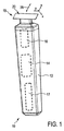
FIG. 1 schematically illustrates an exemplary embodiment of a
カット機器10は、切断ヘッド18を更に有していてもよい。切断ヘッド18において、刃のセット20が、ヘアカット機器10に取り付けられ得る。刃のセット20は、切断動作を可能とするために、駆動機構16を介して、モータ14により駆動され得る。
The cutting
切断動作は、一般的に、図2乃至図18においてより詳細に図示され、以下において詳述される固定刃22と可動刃24との間の相対運動としてみなされてもよい。一般的に、ユーザは、毛を切るために、カット機器10を把持し、毛を通して移動方向28にガイドし得る。幾つかのアプリケーションでは、カット機器10、又は、より具体的には、刃のセット20を含む切断ヘッド18は、肌において成長する毛を切断するために肌に沿って移動されることができる。肌の近くで毛を切断する場合、肌の高さにおいて切断(又は、切る)ことを目的として、基本的に、シェービング動作が、実行され得る。しかしながら、クリッピング(又は、トリミング)動作、即ち、刃のセット20を有する切断ヘッド18が、肌に対して所望の距離における経路に沿って移動されることが想定され得る。従来技術の刃は、一般的に、肌近くにおける滑らかなシェービングと、肌から距離を空けた切断(又は、トリミング)との両方を供給することができない。
The cutting operation may generally be viewed as relative movement between the fixed
毛に沿ってガイド又は導かれる場合、刃のセット20を含むカット機器10は、一般的に、図1において参照符号28により示される共通の移動方向に沿って移動される。これに関し、ヘアカット機器10が一般的に手動でガイド及び移動されるとすると、移動方向28は、必ずしも、カット機器10及びその刃のセット20に適合する切断ヘッド18の向きについての固定の定義及び関連を持つ正確な幾何学的基準エンティティであるとして解釈される必要はないことは言及する価値がある。つまり、肌において切断される毛に対するヘアカット機器10の全体の向きは、幾らか不規則であると解釈され得る。しかしながら、図示目的のため、(仮想的な)移動方向は、以下、刃のセット20の構造的特徴を説明するための手段として機能する座標系の主軸に対して平行(又は、およそ平行)であると正しく仮定されることができる。
When guided or guided along the bristles, the cutting
参照しやすいように、座標系は、図1乃至図18の幾つかにおいて示されている。一例として、直交座標系X−Y−Zが、図1乃至図13の幾つかにおいて示されている。各座標系のX軸は、本開示の目的のため、一般的に長さに関連している長手方向において延在している。座標系のY軸は、本開示の目的のため、一般的に幅に関連している横方向(又は、側面方向)において延在している。座標系のZ軸は、説明の目的のため、少なくとも幾つかの実施形態において、一般的に垂直な方向として、高さ又は厚み方向において延在している。固定刃の特徴及び/又は拡がりに対する座標系の関連性は、主に、説明目的のために供給されており、本発明を限定するものとして解釈されるべきではないことは言うまでもない。当該技術分野における当業者は、代替的な実施形態、異なる向きを含む図面及び図示に直面した場合、ここで供給される座標系を容易に変換及び/又は変形することができることが理解されるべきである。これに関し、注目すべきは、図2乃至図13において図示される刃のセット20の(線形的な)実施形態は、一般的に、ただ1つの長手方向端部において、単一の歯切断エッジを有する単一側面レイアウト、又は、固定刃22及び移動刃24の各歯先端エッジによって相互に規定される2つの一般的に対向する歯切断エッジを有する2重側面レイアウトを含んでいてもよいことである。
For ease of reference, the coordinate system is shown in some of FIGS. As an example, an orthogonal coordinate system XYZ is shown in some of FIGS. The X axis of each coordinate system extends in a longitudinal direction that is generally related to length for the purposes of this disclosure. The Y-axis of the coordinate system extends for the purposes of this disclosure in the lateral (or lateral) direction that is generally related to width. The Z-axis of the coordinate system extends in the height or thickness direction as a generally vertical direction in at least some embodiments for illustrative purposes. It will be appreciated that the relevance of the coordinate system to the fixed blade features and / or spread is provided primarily for illustrative purposes and should not be construed as limiting the invention. Those skilled in the art should understand that the coordinate system provided herein can be easily transformed and / or modified when faced with alternative embodiments, drawings and illustrations including different orientations. It is. In this regard, it should be noted that the (linear) embodiment of the set of
図14,図15a及び図15bに示される刃のセット20aの代替的な実施形態と関連して、代替的な座標系が、主に説明目的のために提示されている。図14に見られるように、基本的に高さ(又は厚み)を示している直交座標系の軸Zに対応し得る中心軸Lを持つ極座標系が提供されている。また、中心軸Lは、回転の中心軸とみなされてもよい。さらに、中心軸Lからの半径方向又は距離rが、図14,図15a及び図15bに示されている。また、角度位置を示している座標δ(デルタ)が、基準半径方向と現在の半径方向との間の角度を図示するように供給されていてもよい。さらに、湾曲矢印t´、特に、円周方向の矢印t´が、図14,図15a及び図15bに図示されている。湾曲矢印t´は、円周方向及び/又は接線方向を示し、これらは、図14に示される真っ直ぐな接線方向の矢印tによっても示されている。ある実施形態と関連して説明される本開示の幾つかの態様が、特定の開示の実施形態に現在されず、従って、直交座標系又は円筒座標系と関連して紹介及び提示されるかどうかに関わりなく、他の実施形態に容易に変形及び適用されることができることが、当該技術分野における当業者によって、容易に理解されるであろう。 In connection with the alternative embodiment of the blade set 20a shown in FIGS. 14, 15a and 15b, an alternative coordinate system is presented primarily for illustrative purposes. As can be seen in FIG. 14, a polar coordinate system is provided having a central axis L that can correspond to an axis Z of an orthogonal coordinate system that basically indicates height (or thickness). Further, the central axis L may be regarded as the central axis of rotation. Furthermore, the radial direction or distance r from the central axis L is shown in FIGS. 14, 15a and 15b. Also, coordinates δ (delta) indicating the angular position may be supplied so as to illustrate the angle between the reference radial direction and the current radial direction. Furthermore, a curved arrow t ′, in particular a circumferential arrow t ′, is illustrated in FIGS. 14, 15a and 15b. Curved arrows t ′ indicate circumferential and / or tangential directions, which are also indicated by straight tangential arrows t shown in FIG. Whether some aspects of the present disclosure described in connection with certain embodiments are not present in the specific disclosed embodiments and thus are introduced and presented in connection with orthogonal or cylindrical coordinate systems Regardless, it will be readily appreciated by those skilled in the art that other embodiments can be readily modified and applied.
可動刃24と固定刃22との間の切断動作は、基本的には、例えば、図3(参照符号30)で示される、線形的な相対運動、特に、往復線形運動を含んでいてもよい。しかしながら、特に、図14,図15a及び図15bに示される実施形態と関連して、固定刃22と可動刃24との間の相対的な切断運動が、(相対的な)回転を含んでいてもよいことが理解されるであろう。切断回転運動は、単一方向の回転を含んでいてもよい。さらに、代替的には、切断運動は、双方向の回転、特に振動を含んでいてもよい。線形的及び/又は回転切断運動を可能にする、カット機器10のための駆動機構16の幾つかの配置が、当該技術分野において知られている。特に、振動切断運動を参照して、湾曲した又は円形の刃のセット20aは、必ずしも、完全な円形態様で形作られる必要はないことを更に留意する。対照的に、湾曲した又は円形の刃のセット20aは、単なる円形セグメント又は湾曲セグメントとして形作られてもよい。また、これに関し、当該技術分野における当業者は、特に、極めて大きな半径を持つ回転切断運動のために構成された円形の刃のセット20aは、理解のために、特に、各先端エッジの一部又は円形セグメントのみが考えられる場合、およそ線形形状の刃のセットとして解釈され得ることを理解することを言及する価値があるであろう。結果、線形的な実施形態を規定及び説明するための直交座標系も、図14に変形及び図示され得る。
The cutting operation between the
図2乃至図13は、図1に説明される線形形状の刃のセット20の実施形態及び態様を図示している。図2及び図3に見られるように、刃のセット20は、固定刃22(即ち、一般的に、カット機器10のモータ14によって直接的には駆動されない刃のセット20の刃)を有する。さらに、刃のセット20は、可動刃24(即ち、カット機器10に取り付けられた場合、固定刃22に関して切断運動を生成するためにモータ14によって駆動され得る刃のセット20の刃)を有する。線形的な(往復)切断運動が、参照符号30で示される両方向矢印によって、図3に図示されている。換言すれば、可動刃24は、側面方向(又は、横方向)(図3におけるY軸を参照)に沿って、固定刃22に対して移動され得る。一般的に、線形切断運動は、相対的に小さい双方向ストロークを含んでいてもよく、従って、往復線形運動として解釈され得る。さらに、(想定される)移動方向28が図3に図示されている。理論上は、毛を切る場合、カット機器10、ひいては刃のセット20は、横方向又は側面方向Yに対して直交する方向28に沿って移動されるべきである。この図14,図15a及び図15bに示される円形の又は湾曲した刃のセット20aの代替的な実施形態に関し、更に言及すると、この形状に関し、(仮想的な)理想の移動方向28は、切断される毛を通ってガイドされる送り運動の間、刃のセット20aの前方向の先端において、接線方向又は円周方向tに対して直交していることが明確になる。換言すれば、湾曲した、又は、円形の刃のセット20aの実施形態のための理想の移動方向28は、一般的に、実際の先端に対して中心軸Lから延在している実際の半径方向rとと一致し得る。
2-13 illustrate embodiments and aspects of the linear shaped blade set 20 illustrated in FIG. As seen in FIGS. 2 and 3, the blade set 20 has a fixed blade 22 (ie, the blades of the blade set 20 that are generally not driven directly by the
しかしながら、動作中、実際の送り運動方向は、(仮想的な)理想の移動方向28とは著しく異なることが強調される。従って、恐らく、動作中、軸運動方向は、横方向Y又は接線方向tに対して完全に垂直ではなく、その結果、長手方向Xに対して完全に平行ではないであろうことが理解されるべきである。
However, it is emphasized that during operation, the actual feed movement direction is significantly different from the (virtual)
図2乃至図13に示される刃のセット20の線形的な実施形態に戻って、切断方向30において可動刃24を駆動するため可動刃24に結合され得る駆動係合部材26を図示している図3に対して更なる説明がなされる。この目的のため、駆動係合部材26は、可動刃24に取り付けられる、又は、固定されていてもよい。刃のセット20が、カット機器10に取り付けられている場合、駆動係合部材26は、動作中、モータ16によって駆動されるために、駆動機構16に結合されていてもよい。
Returning to the linear embodiment of the blade set 20 shown in FIGS. 2-13, a
図4において最もよく分かるように、図2及び図3に関して、高さ方向Zに対して垂直な上面から見た場合に、刃のセット20は、基本的に、矩形の形状又は外形を有していてもよい。固定刃22は、長手方向端部において、少なくとも1つの先端エッジ32,34を有していてもよい。より具体的には、少なくとも1つの先端エッジ32,34は、本開示の目的のため、少なくとも1つの歯先端エッジ32,34について示していてもよい。図4に示される実施形態によれば、固定刃22は、第1の先端エッジ32及び第2の先端エッジ34を有し、第1の先端エッジ32及び第2の先端エッジ34は、互いに反対を向いている。先端エッジ32,34の各々は、複数の突起部36及びその間の各スロットを備えていてもよい。幾つかの実施形態では、突起部36は、実質的に、長手方向X(又は、半径寸法r)において突出している。換言すれば、突起部36の長手方向の拡がりは、側面方向又は横方向Y(又は、接線方向t)に沿った幅の拡がりよりも極めて大きくてもよい。説明の目的のためであって、限定する意図であると理解されるべきでないが、突起部36は、以下では、長手方向に延在している突起部36として示されてもよい。長手方向に延在している突起部36は、それぞれ外側を向いている先端38を有していてもよい。長手方向に延在している突起部36は、固定刃22の各歯40を規定していてもよい。各先端エッジ32,34に沿って、歯40は、各歯スペース42と交互に現れ得る。刃のセット20の例示的な実施形態は、約8mm乃至約15mmの範囲にある、好ましくは約8mm乃至約12mmの範囲にある、より好ましくは約9.5mm乃至約10.5mmの範囲にある全体長手方向寸法lloを有していてもよい。刃のセット20は、約25mm乃至約40mmの範囲にある、好ましくは約27.5mm乃至約37.5mmの範囲にある、より好ましくは約31mm乃至約34mmの範囲にある全体横方向拡がりltoを有していてもよい。この点においては、図18も参照されたい。しかしながら、この例示的な実施形態は、全体の開示の範囲を限定するものとして解釈されるべきではない。
As best seen in FIG. 4, with respect to FIGS. 2 and 3, the set of
本開示に従った刃のセット20,20aは、広い適用性を提供し、好ましくは、シェービング及びトリミング(又は、クリッピング)動作の両方をカバーする。これは、少なくとも部分的に、可動刃24を少なくとも部分的に包囲及び収容し得る固定刃の筺体機能のためである。さらに、図5及び図6を参照すると、図4の線分V−Vに沿った刃のセット20の側面断面図、及び、各詳細図が、示されており、以下説明される。図5から分かるように、固定刃22は、第1の壁部分44と、第2の壁部分46と、その間に配置された中間壁部分48と、を有していてもよい。図5及び図6と関連して、各壁部分44,46,48の網掛け部分が、固定刃22が、必ずしも個別の層又は薄片からなっている必要はないことを示していてもよいことが認められているが、幾つかの実施形態では、固定刃22は、実際は、第1の壁部分44、第2の壁部分46、及び、中間壁部分48を形成している単一の一体的部分からなっていてもよいことに留意すべきである。あるいは、幾つかの実施形態において、固定刃22は、2つの別個の部分からなっていてもよく、当該部分の少なくとも1つは、第1の壁部分44、第2の壁部分46、及び、中間壁部分48のうちの少なくとも2つを形成してもよい。さらに、幾つかの代替的な実施形態では、第1の壁部分44、第2の壁部分46、及び、中間壁部分48のうちの少なくとも1つが、2つ以上の層又はセグメントからなっていてもよいことに留意する価値がある。
A set of
ここで用いられる、第1の壁部分44なる用語は、一般的に、カット機器10の動作中、肌に面している固定刃22の壁部分を表している。結果、第2の壁部分46は、動作中、肌から離れる方向を向いており、カット機器10の筺体12の方を向いている固定刃の壁部分とみなされ得る。引き続き図4を参照すると、図11の拡大図を特に参照して、固定刃22の好適な実施形態が説明される。図11は、図3にも表されている刃のセット20の拡大斜視図を示している。図11から分かるように、好ましい実施形態では、第1の壁部分44は、第1の壁セグメント50、特に第1の層50によって形成され得る。第1の層50は、肌に面する層としてみなされ得る。第2の壁部分は、第2の壁セグメント52、特に第2の層52によって形成され得る。第2の層52は、動作中、肌から離れる方向を向いている層としてみなされ得る。中間壁部分48は、中間壁セグメント54、特に中間層54によって形成され得る。これらを組み立て、固定する場合、中間層54は、第1の層50と第2の層52との間に配置される。
As used herein, the term
図11において最もよく分かるように、中間層54は、必ずしも、単一の一体的な部分である必要はない。代わりに、少なくとも高度な製造過程において、少なくとも中間層54は、以下、より詳細に示され、説明されるように、複数の別個のサブ部品からなっていてもよい。これらをまとめた場合、例えば、しっかりと相互接続した場合、第1の層50、第2の層52、及び、中間層54は、セグメント化されたスタック56、より好ましくは、積層56を規定し得る。例示的な実施形態では、積層56は、三重積層56としてみなされ得る。固定刃22を複数の壁部分44,46,48で形成する、又は、好ましくは、複数の層50,52,54で形成することは、基本的に、別個の単一部分又は異なるタイプ及び形状の層の利用を可能とする。例えば、特に図6を参照すると、(平均)厚さt1としても称される、第1の壁部分44(又は、第1の層50)の高さ寸法t1は、(平均)厚さt2としても称される、第2の壁部分46(又は、第2の層52)の高さ寸法t2とは異なっていてもよく、(平均)厚さtiとしても称される、中間壁部分48(又は、中間層54)の高さ寸法tiと異なっていてもよい。この態様において、壁部分44,46,48(又は、層50,52,54)の各々が、意図された機能に適切に適合する別個の特性及び別個の形状を持ち得るため、これは、特に有用である。
As best seen in FIG. 11, the
例えば、厚さt2は、厚さt1よりも著しく大きくてもよい。この態様では、第2の壁部分46(又は、第2の層52)は、補強部材として機能し、かなりの剛性を供給し得る。結果、第1の壁部分44(又は、第1の層50)は、固定刃22を柔らかくし過ぎることなく、極めて薄くなることができる。特に、薄い第1の壁部分44(又は、第1の層50)を供給することは、肌に近い、特に肌の高さにおける毛の切断を許容する。この態様では、滑らかなシェービング体験が達成され得る。スタック56の全体の高さ寸法toは、基本的に、各部分高さ寸法t1,t2,tiによって規定される。これに関し、幾つかの実施形態では、第1の壁部分44(又は、第1の層50)の厚さt1と第2の壁部分46(又は、第1の層52)の厚さt2とが、同一、又は、少なくとも、実質的に同一であってもよいことに留意する価値がある。他の実施形態では、中間壁部分48(又は、中間層54)の厚さtiも同じであってもよい。
For example, the thickness t 2 may be significantly greater than the thickness t 1. In this aspect, the second wall portion 46 (or the second layer 52) can function as a reinforcing member and provide significant stiffness. As a result, the first wall portion 44 (or the first layer 50) can be very thin without making the fixed
一例として、少なくとも少なくとも1つの先端エッジ32,34における厚さt1は、約0.04mm乃至約0.25mmの範囲、好ましくは約0.04mm乃至約0.18mmの範囲、より好ましくは約0.04mm乃至約0.14mmの範囲にあってもよい。少なくとも少なくとも1つの先端エッジ32,34における厚さt2は、約0.08mm乃至約0.4mmの範囲、好ましくは約0.15mm乃至約0.25mmの範囲、より好ましくは約0.18mm乃至約0.22mmの範囲にあってもよい。少なくとも少なくとも1つの先端エッジ32,34における厚さtiは、約0.05mm乃至約0.5mmの範囲、好ましくは約0.05mm乃至約0.2mmの範囲にあってもよい。少なくとも少なくとも1つの先端エッジ32,34における全体厚さtoは、約0.3mm乃至約0.75mmの範囲、好ましくは約0.4mm乃至約0.5mmの範囲にあってもよい。
As an example, the thickness t 1 at the at least one
幾つかの実施形態では、一般的に、少なくとも、先端エッジ32,34における長手方向の突起部において、第1の壁部分44が、第2の壁部分46の平均厚さt2よりも小さい平均厚さt1を持つことが好ましい。また、本開示の固定刃22,22aの全ての実施形態が、先端エッジにおいて、第1の壁部分44の平均厚さt1よりも大きい、平均厚さt2を持つ第2の壁部分46を少なくとも先端エッジにおいて含む必要はないことに留意する。
In some embodiments, generally, at least at the longitudinal protrusions at the
引き続き図5を参照すると、固定刃22の少なくとも1つの先端エッジ32,34における少なくとも1つの充電領域58が示されている。充填部分58は、先端エッジ32,34において第1及び第2の壁部分44,46(又は、層50,52)を接続する中間壁部分48(又は、中間層52)の一部としてみなされ得る。図5,図6,図10及び図11から分かるように、少なくとも完成した状態において、充電領域58は、各先端エッジ32,34における歯40の数に対応し得る複数のサブ部分からなっていてもよい。先端エッジ32,34における充電領域58に隣接して、固定刃22が、少なくとも部分的に、可動刃24を包囲する、少なくとも1つの筺体領域92が供給されていてもよい。換言すれば、切断動作中、カット機器10のモータ14によって駆動される場合、少なくとも1つのガイドスロット76(特に、図3,図9,図10及び図16c参照)が、可動刃24のためのガイド経路として機能するように規定され得る。図10,図11,図16a及び図16cから最もよく分かるように、ガイドスロット76は、基本的に、中間壁部分48(又は、中間層54)における切り出し部分68によって、規定され得る。幾つか実施形態では、切り出し部分68は、固定刃22の側面端部又は横方向端部に延在しており、これにより、製造中、可動刃24が、固定刃22に挿入され得る、側面開口78を規定している(図9及び図10参照)。
With continued reference to FIG. 5, at least one charging
ガイドスロット76は、図2乃至図13に図示される刃のセット20の例示的な線形的実施形態の可動刃24のための線形の経路を規定してもよい。しかしながら、図14,図15a及び図15bに示される刃のセット20aの湾曲又は円形の実施形態を参照すると、ガイドスロット76は、湾曲した経路、特に、(湾曲した又は円形の)可動刃24の各々のための円周方向に延在している経路を規定してもよい。
The
図5に戻り、更に、図11を参照して、基本的に横方向及び長手方向に延在している固定刃の表面80,82,84,86,88及び90が説明される。参照しやすいように、第1の層50、第2の層52、中間層54なる用語は、以下では、固定刃22の一般的なレイアウトを説明するために用いられる。しかしながら、これは、限定する意図で解釈されるべきではなく、従って、層なる用語は、オプションで、それぞれ、壁部分及び壁セグメントなる代替的な用語で置き換えられてもよいことが強調される。
Returning to FIG. 5 and with further reference to FIG. 11, the
動作中、肌の方を向いている第1の層50は、肌から離れる方を向いている第1の表面80と、肌の方を向いている第2の表面86と、を有していてもよい。第2の層52は、肌から離れる方を向いている第2の表面88と、肌及び第1の層50の方を向いている第1の表面90と、を有していてもよい。中間層54は、第1の層50の方を向いている第1の表面84と、第2の層52の方を向いている第2の表面90と、を有していてもよい。第1の層50及び第2の層52の第1の表面80,82の各々は、少なくとも部分的に、中間層における切り出し部分68を覆っていてもよく、少なくとも1つの筺体領域92、ひいては、可動刃24のためのガイドスロット76を規定していてもよい。
In operation, the
少なくとも1つの先端エッジ32,34において、特に、固定刃22の第1の層50の肌に面する第2の表面86において、少なくとも1つの移行領域94が、滑らかな移行領域94を示し得るように備えられていてもよい。図5及び図6に示される固定刃22の例示的な実施形態は、各長手方向端において、各先端エッジ32,34を有するため、2つの各移行領域94が設けられ得る。少なくとも1つの移行領域は、毛を切断するために肌の上の毛を通る移動方向28に沿って動かされた場合に、刃のセット20のスライド可能特性を高めることができる。特に、少なくとも1つの移行領域94は、刃のセット20、特に、切断のために使用される先端エッジ32,34が、肌に沿ってスライドされた場合に、肌部分に深く入ることを防止する。このようにして、皮膚炎が避けられ得る。好ましくは、このようにして、皮膚切開も避けられ得る、又は、少なくとも、大幅にその可能性が減少し得る。移行領域94は、第1の層50の平坦領域98に接続され、そこから延在していてもよい。この実質的に平坦な領域98は、基本的に、第1の層50の第2の表面86の平面形状の部分としてみなされてもよい。一般的に、ここで用いられる、実質的に平坦なる用語は、平面形状を含み得るが、わずかに不均一な表面も含み得る。実質的に平坦な領域98は、全体的な平坦又は平面形状を実質的に損なわない、小さい凹みなどの穿孔を有していてもよいことに言及する価値がある。幾つかの実施形態では、実質的に平坦な領域98は、平面を含み得る。これは、特に、少なくとも第1の層50が、本来的に、シート又はシート状材料として供給される場合に適用される。移行領域94は、先端エッジ32の相当部分に及んでいてもよい。特に、移行領域94は、第1の層50における実質的に平坦な領域98と第2の層52における実質的に平坦な領域100とを接続してもよい。また、実質的に平坦な領域100は、平坦又は平面領域として形作られていてもよいが、その全体的な平坦形状を損なわない(小さい)穿孔又は凹みを備えていてもよい。
At least one
図4から最もよく分かるように、線分V−Vを参照すると、図5及び図6に図示された断面は、先端エッジ32,34の歯40の先端102を通る長手方向の断面を含む。結果、移行領域94も、歯先端エッジ32,34の歯40において、主に形成され得る。移行領域94は、固定刃22の歯先端102と実質的に平坦な領域98との間に、長手方向の拡がりlt1を有していてもよい。一例として、長手方向の拡がりlt1は、約0.5mm乃至約1.5mmの範囲、好ましくは約0.6mm乃至約1.2mmの範囲、より好ましくは約0.7mm乃至約0.9mmの範囲にあってもよい。さらに、移行領域94は、幾つかのセクションを有していてもよい。図5及び図6から分かるように、移行領域94は、実質的に平坦な領域98,100に接線方向に合流する実質的な凸面を有していてもよい。さらに、移行領域94は、実質的に平坦な領域98(即ち、高さ方向Z)から突き出ていない。換言すれば、移行領域94は、実質的に平坦な領域98から後方へ、さらに、第2の層52の方へ向かって延在し得る。移行領域94は、少なくとも部分的に、高さ方向Zにおいて、実質的に平坦な領域98から離れるように延在し得る。
As best seen in FIG. 4, with reference to line segment V-V, the cross section illustrated in FIGS. 5 and 6 includes a longitudinal cross section through the
図6から最もよく分かるように、移行領域94は、底半径Rtbを有していてもよい。一例として、底半径Rtbは、約1.0mm乃至約5.0mmの範囲、好ましくは約2.0mm乃至約4.0mmの範囲、より好ましくは約2.7mm乃至約3.3mmの範囲にあってもよい。さらに、先端の丸み116が、少なくとも1つのエッジ半径を含み得るように供給されてもよい。特に、先端の丸み116は、第1のエッジ丸みRt1と、第2のエッジ丸みRt2とをを有していてもよい。一例として、第1のエッジ丸みRt1は、約0.10mm乃至約0.50mmの範囲、好ましくは約0.15mm乃至約0.40mmの範囲、より好ましくは約0.20mm乃至約0.30mmの範囲にあってもよい。また、一例として、第2のエッジ丸みRt2は、約0.03mm乃至約0.20mmの範囲、好ましくは約0.05mm乃至約0.15mmの範囲、より好ましくは約0.07mm乃至約0.10mmの範囲にあってもよい。底半径Rtb、第1のエッジ丸みRt1、及び、第2のエッジ丸みRt2は、互いに、接線方向で合流してもよい。しかしながら、代替的に又は追加的に、それぞれの真っ直ぐな部分が、各半径に接線方向で接続され得るように、その間に供給され得る。底半径Rtbは、実質的に平坦な領域98に接線方向で合流してもよい。また、第2のエッジ丸みRt2は、実質的に平坦な領域100に接線方向で合流してもよい。
As best seen in FIG. 6, the
しかしながら、図7a及び図8から最もよく分かるように、移行領域94も、底半径Rtbを置換又は補完し得る傾斜部分124を備えていてもよい。傾斜部分124は、長手方向X及び横方向Yと実質的に並行な水平面に対して面取り角α(アルファ)を有していてもよく、ここで、面取り角αは、約25°乃至約35°の範囲にあってもよい。好ましくは、傾斜部分は、実質的に平坦な領域98に接線方向で合流する。より好ましくは、傾斜部分124は、先端の丸み116に接線方向に合流する。図4から分かるように、線分VII−VIIを参照すると、図7aは、歯スペース42を含む歯のセット20の部分断面図を示している。
However, as best seen in FIGS. 7a and 8, the
換言すれば、移行領域94は、底半径Rtbと傾斜部分124との組み合わせを含んでいてもよい。換言すれば、底半径Rtbは、実質的に平坦な領域98と面取り角αを含む傾斜部分124との間の接線方向の移行として機能してもよい。傾斜部分124の長手方向の端部に面する端部において、傾斜部分124は、例えば、上述の第1のエッジ丸みRt1と第2のエッジ丸みRt2とによって規定され得る先端の丸み116に接線方向で合流してもよい。
In other words, the
さらに、図11及び図4を参照して、可動刃24のレイアウトが、より詳細に説明される。可動刃24も、少なくとも1つの先端エッジを備えていてもよい。図4及び図11に示される刃のセット20の例示的な実施形態によって示されるように、可動刃24は、第1の先端エッジ106と、第2の先端エッジ108とを有していてもよい。先端エッジ106,108の各々は、複数の歯110を備えていてもよい。可動刃24と固定刃22との間の相対的な切断動作を可能にするために適合された刃のセット20の幾つかの実施形態において、ただ1つの固定刃先端エッジ32と、それぞれ単一の可動刃先端エッジ106とが供給され得ることは言うまでもない。しかしながら、多くのアプリケーションのために、固定刃22における2つの先端エッジ32,34と、可動刃24における2つの対応する先端エッジ106,108とを含む刃のセット20の構成が、特に有用であろう。これは、カット機器10が、より柔軟になり、例えば、切断性能を改善し得る移動方向28に沿った肌における前後の動きなどのカット動作を許容し得るためである。換言すれば、図2乃至図13に図示される刃のセット20の実施形態は、一般的に、刃22,24のただ1つの長手方向端部において単一の切断エッジを有する単一側面レイアウト、又は、各先端エッジ32,34及び106,108によって相互に規定される2つの一般的に対向する切断エッジを有する両面レイアウトに関するものである。
Furthermore, with reference to FIG.11 and FIG.4, the layout of the
図12及び図13を参照して、固定刃22の歯40及び可動刃24の歯110の関連寸法が説明される。図12は、刃のセット20の歯部分の部分的な拡大上面図を図示しており、図13は、点線によって隠された端部を示すことによって、図12に示される図を詳述している。固定刃22の歯40は、ピッチ寸法pで配置されている。一例として、ピッチpは、約0.4mm乃至約1.0mmの範囲、好ましくは約0.5mm乃至約0.8mmの範囲、より好ましくは約0.6mm乃至約0.7mmの範囲にあってもよい。また、歯40は、横方向の拡がりWtsを有する。一例として、横方向の拡がりWtsは、約0.25mm乃至約0.60mmの範囲、好ましくは約0.30mm乃至約0.50mmの範囲、より好ましくは約0.35mm乃至約0.45mmの範囲にあってもよい。固定刃の歯スペース42は、横方向の拡がりWssを有する。一例として、横方向の拡がりWssは、約0.15mm乃至約0.40mmの範囲、好ましくは約0.20mm乃至約0.33mmの範囲、より好ましくは約0.25mm乃至約0.28mmの範囲にあってもよい。また、歯40は、その先端102と各歯のベース104との間に、長手方向の拡がりltsを有する。一例として、長手方向の拡がりltsは、約0.6mm乃至約2.5mmの範囲、好ましくは約1.0mm乃至約2.0mmの範囲、より好ましくは約1.5mm乃至約2.0mmの範囲にあってもよい。
With reference to FIGS. 12 and 13, the relevant dimensions of the
また、対応して、可動刃24の歯は、長手方向寸法ltm、(平均の)横方向の歯の拡がりwtm、及び、(平均の)横方向の歯スペースの拡がりwsmを有していてもよい。一例として、長手方向の拡がりltmは、約0.15mm乃至約2.0mmの範囲、好ましくは約0.5mm乃至約1.0mmの範囲、より好ましくは約0.5mm乃至約0.7mmの範囲にあってもよい。また、固定刃22の歯40の先端102と可動刃24の歯110の先端112との間において、長手方向のオフセット寸法lotが規定される。一例として、長手方向のオフセット寸法lotは、約0.3mm乃至約2.0mmの範囲、好ましくは約0.7mm乃至約1.2mmの範囲、より好ましくは約0.8mm乃至約1.0mmの範囲にあってもよい。図13に示されるような、上面図から分かるように、固定刃22の歯40の先端102は、テーパ角度β(ベータ)を有していてもよい。テーパ角度βの各脚の間に、先端102の端部において、丸い先端部分が、横方向の歯の先端幅wttを有して設けられてもよい。幾つかの実施形態では、先端102のテーパ角度βは、約30°乃至約50°の範囲、より好ましくは約35°乃至約45°の範囲、更に好ましくは約38°乃至約42°の範囲にあってもよい。刃の先端102の横方向の幅は、約0.12mm乃至約0.20mmの範囲、好ましくは約0.14mm乃至約0.18mmの範囲にあってもよい。
Correspondingly, the teeth of the
図5及び図6に戻り、刃のセット20のセグメント化された構造の形状の更に有用な側面が、より詳細に図示及び説明される。図6から最もよく分かるように、可動刃24の歯110と固定刃22の歯40とが位置決めされ(図4の線分V−Vも参照)、規定される隙間部分118が、固定刃充填領域58の内側に面する端面114と可動刃24の歯110の先端112との間に設けられる(図13も参照)。隙間部分118は、隙間長手方向寸法lclと、隙間高さ寸法tclとを有する。隙間長手方向寸法lcl及び隙間高さ寸法tclは、少なくとも高い確率で、毛が隙間部分118に入ることがないように、適切に規定される。例えば、十分なスペースが、1本の毛が容易に、可動刃24の歯110の先端112と固定刃充填領域58の端面114との間の隙間に入ることを可能にするために設けられる場合、かかる毛は、そこに詰まり、又は、挟まる。これは、切断能力を損ない得る。さらに、詰まった毛は、切断されるというよりも、むしろ引きちぎられる。これは、しばしば、不快、又は、痛みとして体験され、皮膚をひりひりさせる。従って、隙間部分118によって設けられる(長手方向及び横方向の)スペースは、切断される毛の期待される直径より小さいことが、特に好ましい。このようにして、毛が隙間部分118に入ることによって生じる閉塞のリスクが、著しく低減され得る。多くのケースにおいて、隙間長手方向寸法lcl及び隙間高さ寸法tclのうちの少なくとも1つが、予期される毛の直径よりも小さいことで十分であろう。一例として、隙間長手方向寸法lclは、0.5mmより小さく、好ましくは0.2mmより小さく、より好ましくは0.1mmより小さい。また、一例として、長手方向寸法lclに対して直交する隙間高さ寸法tclは、約0.05mm乃至約0.5mmの範囲、好ましくは約0.05mm乃至約0.2mmの範囲にあってもよい。
Returning to FIGS. 5 and 6, further useful aspects of the shape of the segmented structure of the blade set 20 are shown and described in more detail. As best seen in FIG. 6, the
隙間部分118は、可動刃24の歯110の先端112に隣接する後方部分120と、固定刃充填領域58の端面114における前方部分122とからなっていてもよい。隙間部分118を示している図7aにおいて供給される図の詳細な図である図7bから最もよく分かるように、隙間部分118の前方部分122は、少なくとも1つの半径rcl1,rcl2を有していてもよい。この実施形態では、半径rcl1は、中間層54と第1の層50とを接続していてもよい。半径rcl2は、中間層54と第2の層52とを接続していてもよい。一例として、半径rcl1,rcl2は、約0.025mm乃至約0.25mmの範囲、好ましくは約0.025mm乃至約0.1mmの範囲にあってもよい。
The
図5及び図6に図示された実施形態に戻ると、固定刃22を形成している積層56の層構造は、隙間部分118の長手方向寸法lcl及び隙間高さ寸法tclが広範囲で選択可能であるため、特に有用であることが明らかにされている。固定刃22を積層56として設けることによって、又は、より一般的には、セグメント化されたスタックとして設けることによって、従来技術の刃のセット構造を適用する場合には達成され得ない厳しい許容範囲が、達成され得る。また、図6から分かるように、固定刃22の先端エッジ32,34における充填領域58は、長手方向の拡がりlf1を有していてもよい。一例として、当該長手方向の拡がりlf1は、約0.6mm乃至1.2mmの範囲、好ましくは約0.75mm乃至0.9mmの範囲、より好ましくは約0.8mm乃至0.85mmの範囲にあってもよい。積層56の層50,52,54の各々が、幾何学的特性に関して広くカスタマイズされることができるため、固定刃22は、従来技術の刃のセット構造アプローチを使用する場合に達成され得ないような形状を有し得る。
Returning to the embodiment illustrated in FIGS. 5 and 6, the layer structure of the
隙間高さ寸法tclは、基本的に、中間層54の高さ寸法tiに対応していてもよい。中間層54の高さtiは、正確に規定され、選択され、さらに、精密さを有しているため、少なくとも高さ方向Zにおいて、固定刃22におけるガイドスロット76での可動刃24の隙間適合も達成され得る。中間層54の高さ寸法tiによって規定される隙間高さ寸法tclは、少なくともガイドスロット76にガイドされる領域において、可動刃24が、ガタガタする(過度にゆるい)ことなく、又は、つかえる(過度にきつい)ことなく、滑らかな動作のため、ガイドスロット76において適切にガイドされるように、精密な設計許容誤差内で正確に規定されることができる。最終的な部品の隙間高さ寸法trclが、図6に示されており、基本的に、ガイドスロット76の隙間高さ寸法tclと可動刃24の高さ寸法tmとによって規定されている。一例として、隙間高さ寸法trclは、約0.003mm乃至約0.050mmの範囲、好ましくは約0.005mm乃至約0.030mmの範囲にあってもよい。
The gap height dimension t cl may basically correspond to the height dimension t i of the
図4、図11、及び、図16a〜図16cから最もよく分かるように、中間層54における切り出し部分68は、横方向Y(又は、接線方向t)に沿って移動する場合に、可動刃24をガイドするための内側ガイド部分126を更に規定していてもよい。内側ガイド部分126は、タブ又はストリップとして形成されていてもよい。内側ガイド部分126は、基本的に、固定刃22の長手方向中心部分において配置され得る。内側ガイド部分126の端部において、側面開口78に隣接して、テーパ状の部分128が供給され得る(図9及び図10も参照)。テーパ状の部分128は、可動刃24のためのマウント又は挿入ステップを促進し得る。
As best understood from FIGS. 4, 11, and 16 a to 16 c, the
特に、図11を参照して、本開示に従った例示的な実施形態の可動刃24の構造が、更に詳細に説明される。上面から見た場合(図4参照)、可動刃24は、基本的に、U字形状であってもよく、第1の先端エッジ106と関連付けられた第1の腕部分132と、第2の先端エッジ108と関連付けられた第2の腕部分134と、第1の腕部分132と第2の腕部分134とを接続している接続部分136とを有していてもよい。一例として、接続部分136は、可動刃24の側面端部に設けられてもよく、固定刃22にマウントされた場合、固定刃22の側面開口78の近傍に配置される。換言すれば、第1の腕部分132及び第2の腕部分134は、中間層54における内側ガイド部分126の長手方向の拡がりに適合される長手方向Xにおいて、距離を空けて平行に配置され得る。可動刃24をガイドするために、内側ガイド部分126は、第1の側面延在ガイド表面140と、第2の側面延在ガイド表面142とを有していてもよい(図4参照)。結果、可動刃24は、各腕部分132,134において、内側に面する接触部分146,148を有していてもよい。
In particular, with reference to FIG. 11, the structure of the
幾つかの実施形態では、可動刃24の少なくとも1つの腕部分132,134に配置された少なくとも1つのガイド部分146,148が、少なくとも1つの接触要素150,152、特に、少なくとも1つのガイドタブ150,152を備えていてもよい。一例として、(部分的に隠れた態様における)図4に示される可動刃24は、第1の腕部分132の第1の接触部分146において2つのガイドタブ150を有していてもよい。可動刃24は、第2の腕部分134の第2の接触部分148において2つのガイドタブ152を更に有していてもよい。内側ガイド部分126の側面延在ガイド表面140,142は、長手方向の拡がりlgpだけ離されていてもよい。結果、少なくとも1つの第1の接触要素150(又は、ガイドタブ)及び少なくとも1つの第2の接触要素152(又は、ガイドタブ)は、長手方向隙間寸法lgtだけ離されていてもよい。ガイドタブ150,152の長手方向隙間寸法lgtは、内側ガイド部分126の長手方向の拡がりlgpよりもわずかに大きく選択されることが好ましい。このようにして、滑らかな相対切断運動を可能とする可動刃24のための規定された隙間適合ガイドが達成され得る。一例として、長手方向の拡がりlgp及び長手方向隙間寸法lgtによって規定される最終的な隙間長手方向寸法は、約0.003mm乃至約0.050mmの範囲、好ましくは約0.005mm乃至約0.030mmの範囲にあってもよい。幾つかの実施形態では、固定刃22におけるガイドスロット76が、長手方向寸法X及び高さ(又は、垂直)寸法Zにおいて、可動刃24の形状固定ガイドを備えることにより、横方向Yに沿った滑らかな動きを可能にするが好ましい。言うまでもなく、上述した有用な原理は、図14,図15a及び図15bに示される刃のセット20aの円形の実施形態、又は、より一般的には、湾曲した実施形態へと容易に変換され得る。
In some embodiments, at least one
特に、図15a及び図15bを参照して、(円形の)刃のセット20aの固定刃22aが更に詳述される。図15bにおいて供給される断面図では、網掛けが示されており、これは、固定刃22aが、一体的な部品として形成されてもよいことを示している。しかしながら、固定刃22aも、各可動刃のためのガイドスロット76を相互に規定する第1の壁部分44、第2の壁部分46、及び、中間壁部分48を有していてもよい。また、これに関連して、固定刃22aも、(線形的な)刃のセット及び各固定刃22の幾つかの有用な実施形態の上述の原理に従った層構造を有していてもよいことに留意すべきである。結果、第1の壁部分44、第2の壁部分46、及び、中間壁部分48の各々は、それぞれ、壁部分又は層によって形成されてもよい。上述のように、長手方向などの用語は、円形の実施形態と関連して、半径方向としてみなされ得る。また、側面又は横などの用語は、円形の実施形態と関連して、接線又は円周としてみなされ得る。
In particular, with reference to FIGS. 15a and 15b, the fixed
特に、図16a〜図16fを参照して、また、図17を更に参照して、本開示の幾つかの態様に従った刃のセット20の固定刃22のための例示的な製造方法及び例示的な製造システムが、図示及び詳述される。図16aから分かるように、第1の層50、第2の層52、及び、中間層54のうちの少なくとも1つは、ストリップ材料の形式で供給され得る。第1の層50は、第1のストリップ194から得られてもよい。第2の層52は、第2のストリップ196から得られてもよい。中間層54は、中間ストリップ198から得られてもよい。これに関連する更なる参照が、図18においてなされる。図16aにおいて既に述べたように、ストリップ194,196,198の少なくとも幾つかは、事前に、機械加工又は処理されていてもよい。図16aに図示される準備段階において、切り出し部分68が、中間層54を規定する中間ストリップ198において処理され得る。切り出し部分68は、実質的に、U字形状を有していてもよい。異なる形状が、同様に、想定され得る。特に、切り出し部分68は、第1の脚158、第2の脚160、及び、第1の脚158と第2の脚160とを接続する移行部分162を有していてもよい。第1の脚158、第2の脚160、及び、移行部分162は、中間層54における内側ガイド部分126を規定する。
In particular, with reference to FIGS. 16a-16f, and with further reference to FIG. 17, an exemplary manufacturing method and illustration for a fixed
同様に、第2のストリップ196によって形成された第2の層52も、切り出し部分166を備えていてもよい。例えば、切り出し部分166は、実質的に、U字形状を有していてもよい。異なる形状が、同様に、想定され得る。切り出し部分166は、第1の脚168、第2の脚170、及び、第1の脚168と第2の脚170とを接続する移行部分172を有していてもよい。第1の脚168、第2の脚170、及び、移行部分172は、それらの間に、ガイドタブ174を規定する。一般的に、実際の形状及びサイズに関わらず、切り出し部分166は、駆動係合部材26(これについては、図3参照)が、開口を通じて、固定刃22に関して相対切断運動するように可動刃24に接触し、可動刃24を駆動し得る、固定刃22における開口としてみなされ得る。結果、ヘアカット機器10に適合された場合、第2の層52における切り出し部分166は、動作中、筺体12の方を向いており、肌から離れた方を向いていてもよい。
Similarly, the
また、図16aから分かるように、少なくとも第1の層50、好ましくは各層50,52,54は、実質的に平坦又は平面形状を有していてもよい。ストリップ194,196,198の各々は、金属ストリップとして、特に、ステンレス鋼のストリップとして供給され得る。しかしながら、幾つかの実施形態では、第2の層52及び中間層54の少なくとも1つは、非金属材料などの異なる材料から形成されていてもよい。一般的に、ヘアカット機能自体は、可動刃24の高さにおける各切断エッジと協働する第1の層50(又は、第1の壁部分44)の切断エッジにより、固定刃22の高さにおいて、実行される。従って、しばしば、少なくとも第1の層50が、金属材料から形成される、特に、スレンレス鋼から形成されることが好ましい。層50,52,54の各々は、金属薄板として供給されてもよい。金属薄板は、各金属薄板リールから供給されてもよく、又は、一般的には、金属薄板ブランクから供給されてもよい。
Also, as can be seen from FIG. 16a, at least the
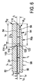
図16bから分かるように、第1の層50、第2の層52、及び、中間層54は、相互接続されることに備えて相互に位置決めされ得る。特に、各層は、接着によって、又は、より好ましくは溶接によって、固定接続され得る。最終的な接着されたストリップが、参照符号208により、図16bにおいて示されている。各層50,52,54の溶接は、特に、レーザ溶接を含み得る。層50,52,54は、各々の先端エッジ(図16bの参照符号210)において接着され得る。さらに、幾つかの実施形態では、層50,52,54は、内側ガイド部分126及びガイドストリップ174が存在する(参照符号212)、長手方向中心部分において接着され得る。溶接は、連続溶接及び/又はスポット溶接の形式を含み得る。
As can be seen from FIG. 16b, the
図16cから分かるように、図16bに図示される相互接続ステップ又は接着ステップに続いて、積層56が、接着されたストリップ208から分離又は切り離される、分離ステップが実行され得る。切り出し部分68及び/又は166の少なくとも小さい側面部分が最終的な積層56から切り離されるように、接着されたストリップ208を切断する場合、側面開口78は、ガイドスロット76がアクセス可能であるように形成され得る。さらに、切断又は分離動作は、積層の基本的に矩形の外形216を規定してもよい。
As can be seen from FIG. 16 c, following the interconnection or bonding step illustrated in FIG. 16 b, a separation step can be performed in which the laminate 56 is separated or separated from the bonded
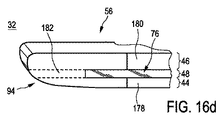
図16dに図示される更なる段階において、積層の少なくとも1つの先端エッジ94が、処理され得る。当該処理は、特に、少なくとも1つの移行領域94(図5、図6、及び、図7aも参照)を規定又は形成するために、材料除去処理を含み得る。図16dから更に分かるように、積層56の先端エッジ32は、歯形成処理の後の歯においても存在する実質的にU字の形状を有していてもよい。特に、ガイドスロット76は、少なくとも部分的に先端エッジ32の中へ長手方向に延在してもよく、結果、第1の歯脚178、第2の歯脚180、及び、接続領域182が規定される。第1の歯脚178は、主に、第1の壁部分44(又は、第1の層50)によって規定され得る。第2の歯脚180は、主に、第2の壁部分46(又は、第2の層52)によって規定され得る。接続領域182は、主に、中間壁部分48(又は、中間層)から形成され得る。先端エッジ94の処理は、材料除去処理、特に、電気化学的機械処理を含み得る。
In a further step illustrated in FIG. 16d, at least one leading
更なる製造段階において、積層56は、少なくとも1つの先端エッジ42において、歯40及び各歯スペース42を更に備えていてもよい。歯の機械処理は、複数の歯40の間を更に規定すべく歯スペースを規定する複数のスロットを形成するための材料除去処理を含み得る。歯の機械処理は、切断動作を含み得る。特に、歯の機械処理は、ワイヤエローディング(wire eroding)を含み得る。図16eから更に分かるように、中間的な製造段階において、歯40は、側面222及び接触表面224が接続される鋭い移行エッジ218を有していてもよい。
In a further manufacturing stage, the laminate 56 may further comprise
図16eに図示された段階に続く、図16fに示される更なる製造段階において、歯が形成された積層56が、更に機械処理される、又は、より一般的には、処理され得る。特に、歯40の形成後に存在し得る鋭いエッジ218は、丸みをつけられてもよい。結果、歯側面エッジ半径Rtleを持つ丸みを帯びたエッジ220が形成され得る。丸みをつけることは、材料除去処理、特に、電気化学的機械処理を含み得る。これに関し、更なる参照が、図8でなされる。一例として、湾曲したエッジ移行の半径Rtleは、約0.05mm乃至約0.07mmの範囲、好ましくは約0.053mm乃至約0.063mmの範囲にあってもよい。
In a further manufacturing stage shown in FIG. 16f, following the stage illustrated in FIG. 16e, the
図16a〜図16fに関連して、各製造段階の順序は、必ずしも、上述の固定的な製造順序に関するものではないことに言及する価値がある。例えば、図16d及び図16eに図示される製造ステップは、シフトされてもよいし、又は、より好ましくは交換されてもよい。さらに、製造方法の幾つかの実施形態において、移行領域及び歯形状を形成するステップは、同時に実行されてもよいし、又は、少なくとも一時的に重複して実行されてもよい。 In connection with FIGS. 16a to 16f, it is worth mentioning that the order of each manufacturing step does not necessarily relate to the fixed manufacturing order described above. For example, the manufacturing steps illustrated in FIGS. 16d and 16e may be shifted or more preferably replaced. Further, in some embodiments of the manufacturing method, the steps of forming the transition region and the tooth shape may be performed simultaneously or at least temporarily overlapped.
図17は、本開示の幾つかの態様に従った固定刃22を製造するための製造システム214を図示している。特に、図16b〜図16fに図示される準備段階及び中間段階の少なくとも幾つかは、製造システム214を用いて、実行又は処理され得る。
FIG. 17 illustrates a
第1の層50、第2の層52、及び、中間層54を形成するための各ストリップ材料194,196,198は、各リール200,202,204から供給され得る。第1のストリップ194は、第1のリール200から供給され得る。第2のストリップ196は、第2のリール202から供給され得る。中間ストリップ198は、中間リール204から供給され得る。フィード方向が、参照符号226によって、図17において示されている。幾つかの実施形態では、リール202,204は、第2の層52及び中間層54のための各切り出し部分68,166を既に有していてもよい。また、充填表面、即ち、各切り出し部分を有さない表面を有する第2のストリップ196及び中間ストリップ198のためのリール材料が供給されることも想定され得る。この場合、製造システム214は、ストリップ196,198において各切り出し部分68,166を形成するための少なくとも1つ切断又はスタンプユニットを更に有していてもよい。
Each
図17に図示される実施形態によれば、リール202,204は、予め製造された、又は、予め処理されたストリップ196,198を有していてもよい。それぞれ、第1の層50、第2の層52、中間層54を形成しているストリップ材料194,196,198が、接着装置228へ供給又は先送りされ得る。一般的に、接着装置228は、相互接続又は固定装置としてもみなされ得る。接着装置228において、ストリップ194,196,198の各部分が、受けられ、支持され、位置決めされ得る。この点において、更なる参照が、予め処理された、又は、予め機械処理されたストリップ194,196,198の上面からの表現を示している図18において、なされる。これに関して、ストリップ194,196,198は、必ずしも、リール200,202,204から供給される必要はないことに留意する。むしろ、シート又はブランクなどの平坦な前製品が、用いられてもよい。ストリップ194,196,198の幾つか、又は、各々は、それぞれ対応している位置決め要素242,244を備えていてもよい。位置決め要素242,244は、長手方向X並びに側面又は横方向Yにおいて、ストリップ194,196,198の各部分の間に相互の位置的なアラインメントを供給し得る。一例として、ストリップ194,196,198における第1の位置決め要素242は、長手方向と横方向(又は、側面方向)との両方において、アラインメントを供給してもよい。さらに、ストリップ194,196,198における第2の位置決め要素244は、一般的に、横方向(又は、側面方向)において、アラインメントを供給してもよい。このようにして、ストリップ194,196,198の位置的な重複が回避され得る。幾つかの実施形態では、位置決め要素242は、円筒孔として形作られ得る。対照的に、位置決め要素244は、細長い孔として形作られ得る。接着又は相互接続装置228において十分に位置決め及びスタック化され、各ストリップ194,196,198は、固定的に相互接続され、好ましくは接着され、より好ましくは溶接され、これにより、接着されたストリップ208が形成される(これに関しては、図16b参照)。
According to the embodiment illustrated in FIG. 17, the
製造システム214は、分離装置230、特に、切断又はスタンプ装置230を更に有していてもよい。分離装置230により、接着装置228によって供給され、分離装置230に送られる、接着されたストリップ208の各部分が、切り離され(切り出され)てもよい。また、これに関連して、図18を参照すると、接着されたストリップ208の分離される部分は、全体的な横方向長さ寸法ltroを有していてもよい。接着されたストリップ208の分離される各部分の間に配置される位置決め要素242,244の各々は、長さ廃棄寸法lwa1及び長さ廃棄寸法lwa2をそれぞれ有する部分に配置されてもよい。換言すれば、横方向全体長さ寸法ltroを持つ複数の積層56を得るために、接着されたストリップ208の各部分を切断する場合、各長さ廃棄寸法lwa1及びlwa2によって、図18において示されるクリッピング又は廃棄部分も接着されたストリップ208から切り離され(切り出され)得る。単なる説明目的のために、接着層208及び積層56が、別個の拡大図として図18において示されていることに言及すべきであろう。また、ストリップ194,196,198は、好ましくは、同一の長手方向の拡がりlloを持っていてもよいことに言及する価値がある。
The
また、図17を参照すると、製造システム214は、歯形状形成装置232、特に、ワイヤエローディング装置232を更に有していてもよい。特に、装置232は、複数の積層56を有するスタック238を同時に処理するように適合されていることが好ましい。歯形状形成装置232では、基本的に長手方向に延在するスロットが、積層56の各先端エッジ32,34において生成され得る(図16e参照)。
Referring to FIG. 17, the
製造システム214は、処理装置又は機械処理装置334、特に、供給された積層56を電気化学的処理又は機械処理をすることが可能な装置を更に有していてもよい。その際、面取り及び/又は丸み付け処理が、積層56における鋭いエッジに対して適用され得る(図16f参照)。幾つかの実施形態では、処理装置234は、積層56において、少なくとも1つの移行領域94を形成又は機械処理することが可能であってもよい(図16d参照)ことに留意すべきである。あるいは、製造システム214は、別個の処理装置又は機械処理装置、特に、電気化学的機械処理が可能な装置を更に有していてもよい。かかる装置は、例えば、分離装置230と歯形状生成装置232との間に介在し、積層の歯40の形成又は生成に先立って、少なくとも1つの移行領域94を形成することが可能である。また、異なる製造段階において、少なくとも1つの移行領域94を処理するために、及び、歯を丸み付け又は面取りするために、基本的に同一の処理装置又は機械処理装置234を利用することが想定され得る。
The
さらに、図19及び図20を参照して、本開示の幾つかの態様に従った固定刃を製造するための方法及び刃のセットを製造するための方法の例示的な実施形態の幾つかのステップが、図示及び詳述される。図19は、刃のセットの固定刃を製造する方法を概略的に図示している。図19において、一般的に、オプションのステップは、点線ブロックにより示されている。まず、ステップ300,304,308において、第1の層、第2の層、及び、中間層を形成するための各ストリップが、供給され得る。ステップ304,308の前に、更なるオプションのステップが実行されてもよい。ステップ302,306は、第2の層が形成され得る第2のストリップ、及び、中間層が形成され得る中間ストリップにおいて、各切り出し部分を形成するステップを含んでいてもよい。しかしながら、代替的に、予め処理された切り出しストリップが供給される場合は、ステップ302,306は、省略されてもよい。オプションの位置決めステップ310が、ステップ300,304,308に続いてもよい。位置決めステップは、分離ステップ310としてみなされ得るが、代替的に、しっかりとした方法で互いの上部で各ストリップを位置決めする次のステップ312に含まれてもよい。ステップ312は、第1のストリップと第2のストリップとの間での中間ストリップの位置決めを更に含んでいてもよい。位置決めステップ310は、各ストリップ部分の長手方向及び/又は側面(又は、横)方向の位置決めを含んでいてもよい。ステップ312の下流において、各ストリップが、固定的に相互接続され得る接続ステップ314が続いてもよい。特に、ステップ314は、接着ステップ、好ましくは溶接ステップを含んでいてもよい。このようにして、接着されたストリップ、特に接着された層構造のストリップが形成され得る。
Further with reference to FIGS. 19 and 20, some of the exemplary embodiments of the method for manufacturing a fixed blade and the method for manufacturing a set of blades according to some aspects of the present disclosure. The steps are shown and detailed. FIG. 19 schematically illustrates a method for manufacturing a fixed blade of a set of blades. In FIG. 19, in general, optional steps are indicated by dotted blocks. First, in
さらに、次のオプションのステップ316では、各スタック部分が、接着されたストリップから分離され得る。これは、接着されたストリップ、より正確には、各層を形成するオリジナルのストリップが、複数の積層セグメントがそこから形成されるように形作られるとともに、然るべき寸法を有する場合に、特に、適用され得る。例えば、第1のストリップ、第2のストリップ、及び、中間ストリップの各々は、細長い金属薄板、特にリール材料として供給されてもよい。このようにして、高次の積層セグメントが、単一のストリップを基に、形成され得る。しかしながら、幾つかの実施形態では、形成される積層の最終的な全体形状に既に適合されているストリップ部分が、ステップ300,304,308において供給されてもよい。この場合、分離ステップ316は、省略され得る。ストリップにおいて供給される別個の位置決め要素を考慮して、ステップ310においてストリップの位置決めが実行される場合、各位置決め部分も、分離ステップ316において、切り抜かれる又は切り出される。
Further, in a next
幾つかの実施形態では、全体的な先端機械処理及び/又は先端平滑化処理318が続いて実行され得る。ステップ318において、少なくとも1つの移行領域が、積層の少なくとも1つの先端エッジにおいて、形成又は処理され得る。ステップ318は、特に、面取り処理、及び/又は、丸み付け処理を有していてもよい。ここで、ステップ318は、電気化学的機械処理として構成されてもよい。また、ステップ320が、オプションのステップ318の下流において(又は、代替的には、上流において)実行され得る。ステップ320は、歯形成ステップ、より明確には、歯切断ステップとしてみなされ得る。例えば、ステップ320は、複数のスロット又は歯スペースを作成するために、積層の少なくとも1つの先端エッジにおける切断動作を含んでいてもよい。ステップ320は、例えば、ワイヤエローディング切断動作を使用してもよい。ステップ320において、歯及び歯スペースを形成する場合、一般的に、歯の鋭いエッジが生成され得る。結果、材料除去歯機械処理動作を含み得る更なるステップ322が続く。特に、ステップ322は、鋭い歯のエッジにおける丸み付け又は面取り動作を有していてもよい。少なくとも1つの切り出し部分が、中間層を形成する中間ストリップにおいて存在するため、層を配置、接続、及び、機械処理するステップが、同時に、可動刃を収容することができる積層におけるガイドスロットを生成してもよい。ステップ322において、積層を含むヘアカット機器のための固定刃が供給され得る。
In some embodiments, an overall tip machine process and / or
ここで、図20を参照すると、ヘアカット機器のための刃のセットを製造する方法の例示的な実施形態が提示されている。当該方法は、ステップ330を有していてもよく、ここで説明された製造方法の幾つかの態様に従って製造された固定刃が供給され得る。固定刃は、固定刃におけるガイドスロットがアクセス可能である、開口、特に側面開口を有することが好ましい。また、ステップ332において、少なくとも1つの歯先端エッジを有する各可動刃24が供給され得る。次いで、可動刃が固定刃のガイドスロットに挿入される組み立てステップ334が供給される。特に、可動刃が、固定刃の側面(横)端部において、側面開口を通ることが好ましい。
Referring now to FIG. 20, an exemplary embodiment of a method for manufacturing a set of blades for a haircut device is presented. The method may include
上述のように紹介及び説明された製造方法は、本開示の幾つかの有用な態様に従って形作られた刃のセットを製造する実施形態のための考えられ得るただ1つの手法であるものとして解釈されるべきではないことを強調する。特に、刃のセットの構造的特徴が、本開示において明らかにされ、説明されたが、これらの特徴は、特定の製造方法に関連している必要はない。固定刃を製造するための幾つかの製造方法が想定され得る。構造的特徴の説明が、上述の製造方法に関しているときはいつでも、このことは、理解のための例示的な追加情報として解釈されるべきであり、開示の製造ステップに本開示を限定するものとして解釈されるべきではない。 The manufacturing method introduced and described as described above is to be construed as being the only possible approach for an embodiment of manufacturing a set of blades shaped in accordance with some useful aspects of the present disclosure. Emphasize that it should not. In particular, although structural features of the blade set have been identified and described in this disclosure, these features need not be related to a particular manufacturing method. Several manufacturing methods for manufacturing the fixed blade can be envisaged. Whenever the description of structural features relates to the manufacturing method described above, this should be construed as exemplary additional information for understanding and as limiting the disclosure to the disclosed manufacturing steps. Should not be interpreted.
さらに、「第1の層」、「第2の層」、及び、「中間層」などの用語がここで固定刃の構造と関連して用いられる場合、これらは、本開示の範囲から逸脱することなく、それぞれ、「第1の壁部分」、「第2の壁部分」、及び、「中間壁部分」により容易に置き換えられ得ることが強調される。「第1の層」、「第2の層」、「中間層」、及び、「積層」なる用語は、本開示を、製造プロセス中に相互接続される前に、実際に(物理的に)互いに区別される、スライスされた(例えば、金属薄板の)サブコンポーネントから実際になる固定刃の実施形態のみに限定するものとして解釈されるべきではない。 Further, where terms such as “first layer”, “second layer”, and “intermediate layer” are used herein in connection with the structure of a fixed blade, they depart from the scope of this disclosure. Without emphasis, it can be easily replaced by “first wall portion”, “second wall portion” and “intermediate wall portion”, respectively. The terms “first layer”, “second layer”, “intermediate layer”, and “laminate” refer to the disclosure (physically) prior to being interconnected during the manufacturing process. It should not be construed to be limited to embodiments of fixed blades that actually come from sliced (eg, sheet metal) subcomponents that are distinct from each other.
言うまでもなく、本開示に従った刃のセットの製造方法の実施形態において、ここで説明される幾つかのステップは、変更された順序で、又は、同時にさえ、実行されることができる。さらに、幾つかのステップは、本発明の範囲から逸脱することなく、省略されてもよい。 Of course, in an embodiment of a method of manufacturing a set of blades according to the present disclosure, some steps described herein can be performed in a modified order or even simultaneously. In addition, some steps may be omitted without departing from the scope of the invention.
ある程度、添付の図面を参照して、本発明の例示的な実施形態がこれまで説明されてきたが、本発明は、これらの実施形態に限定されないことが理解されるべきである。開示の実施形態に対する変形が、図面、開示、及び、添付の請求項の研究から、本発明を実行する当該技術分野における当業者によって、理解及び達成されることができる。「一実施形態」又は「ある実施形態」に対する本開示を通じた符号は、実施形態と関連して説明された特定の特徴、構造、又は、特性が、本開示に従った、固定刃、刃のセット、製造方法の少なくとも1つ実施形態に含まれることを意味する。このため、本開示を通じた様々な箇所における「一実施形態において」又は「ある実施形態において」なる文言の出現は、必ずしも全て同じ実施形態に関するものではない。さらに、1又は複数の実施形態の特定の特徴、構造、又は、特性が、新たな、明示されていない実施形態を形成するために、任意の適切な態様で組み合わせられてもよいことに留意する。 To some extent, exemplary embodiments of the present invention have been described above with reference to the accompanying drawings, but it should be understood that the present invention is not limited to these embodiments. Variations to the disclosed embodiments can be understood and attained by those skilled in the art in practicing the present invention, from a study of the drawings, the disclosure, and the appended claims. References throughout the present disclosure to “one embodiment” or “an embodiment” indicate that the particular features, structures, or characteristics described in connection with the embodiment are fixed blades, blades according to the present disclosure. It is meant to be included in at least one embodiment of a set or manufacturing method. Thus, the appearances of the phrases “in one embodiment” or “in an embodiment” in various places throughout this disclosure are not necessarily all related to the same embodiment. Furthermore, it is noted that the particular features, structures, or characteristics of one or more embodiments may be combined in any suitable manner to form new, unspecified embodiments. .
請求項において、「有する」なる用語は、他の要素又はステップを除外せず、単数形は、複数であることを除外しない。単一の要素又は他のユニットが、請求項に記載された幾つかの項目の機能を果たしてもよい。特定の特徴が、相互に異なる従属項において言及されているという単なる事実は、これらの特徴の組み合わせが好適に用いられないということを示すものではない。 In the claims, the term “comprising” does not exclude other elements or steps, and the singular does not exclude the presence of a plurality. A single element or other unit may fulfill the functions of several items recited in the claims. The mere fact that certain features are recited in mutually different dependent claims does not indicate that a combination of these features cannot be used to advantage.
請求項における任意の参照符号は、本発明の範囲を限定するものとして解釈されるべきではない。 Any reference signs in the claims should not be construed as limiting the scope of the invention.
Claims (16)
動作中、肌に面する壁部分として機能するように構成された第1の壁部分と、第2の壁部分と、中間壁部分と、を有し、少なくとも前記第1の壁部分は、実質的に平坦な態様で延在しており、
前記第1の壁部分、前記第2の壁部分、及び、前記中間壁部分は、固定的に相互接続されており、これにより、セグメント化された層を形成しており、
前記中間壁部分は、前記第1の壁部分と前記第2の壁部分との間に配置され、
前記第1の壁部分、前記第2の壁部分、及び、前記中間壁部分は、実質的に同等の全体的拡がりを有し、これにより、前記セグメント化された層の端部において、少なくとも1つの歯状の先端エッジを協働して形成し、
前記少なくとも1つの先端エッジは、相互に間隔を空けられた各スロットと交互である複数の相互に間隔を空けられた突起部を有し、これにより、複数の歯と各歯のスペースとを規定し、
前記歯状の先端エッジは、少なくとも部分的に、動作中に想定される前記移動方向に対する側面方向において延在しており、前記相互に間隔を空けられた突起部は、少なくとも部分的に、前記側面方向に対しておよそ直交する方向において突出しており、
前記中間壁部分は、少なくとも1つの切り出し部分を有し、前記中間壁部分において設けられた前記少なくとも1つの切り出し部分は、前記セグメント化されたスタックの前記少なくとも1つの先端エッジにおいて、前記中間壁部分の複数の残りの端部を規定しており、
前記中間壁部分における前記少なくとも1つの切り出し部分、前記第1の壁部分、及び、前記第2の壁部分は、これらの間に、可動刃のためのガイドスロットを規定しており、
前記中間壁部分に設けられた前記少なくとも1つの切り出し部分が、前記側面方向に対して直交する断面において見た場合に前記側面方向に対しておよそ直交する前記方向において突出している前記突起部の基本的にU字形状の歯形状を規定するため、前記セグメント化されたスタックの長手方向端部内へ長手方向に延在し、前記U字形状の歯形状が、前記第1の壁部分によって形成された第1の歯脚と、前記第2の壁部分によって形成された第2の歯脚と、前記第1の歯脚と前記第2の歯脚とを接続する前記中間壁部分の残りの端部によって形成された接続領域と、を有する、固定刃。 A segmented fixed blade for a set of blades of a haircut device, wherein the set of blades is configured to move through the hair in the direction of movement to cut the hair, the blade being ,
A first wall portion configured to function as a wall portion facing the skin during operation; a second wall portion; and an intermediate wall portion, wherein at least the first wall portion is substantially Extending in a flat manner,
The first wall portion, the second wall portion, and the intermediate wall portion are fixedly interconnected, thereby forming a segmented layer;
The intermediate wall portion is disposed between the first wall portion and the second wall portion;
The first wall portion, the second wall portion, and the intermediate wall portion have a substantially equivalent overall extent, so that at the end of the segmented layer, at least 1 Forming two tooth-shaped tip edges in cooperation,
The at least one tip edge has a plurality of spaced-apart protrusions alternating with each spaced-apart slot, thereby defining a plurality of teeth and a space for each tooth And
The toothed tip edge extends at least partially in a lateral direction with respect to the direction of movement assumed during operation, and the spaced-apart protrusions are at least partially projects in towards direction you approximately perpendicular to the side surface direction,
The intermediate wall portion has at least one cut-out portion, and the at least one cut-out portion provided in the intermediate wall portion is the intermediate wall portion at the at least one leading edge of the segmented stack. A plurality of remaining ends of
The at least one cutout portion, the first wall portion, and the second wall portion in the intermediate wall portion define a guide slot for a movable blade therebetween,
The base of the protruding portion in which the at least one cut-out portion provided in the intermediate wall portion protrudes in the direction approximately orthogonal to the side surface direction when viewed in a cross section orthogonal to the side surface direction. To generally define a U-shaped tooth shape extending longitudinally into the longitudinal end of the segmented stack, the U-shaped tooth shape being formed by the first wall portion. A first tooth leg, a second tooth leg formed by the second wall part, and a remaining end of the intermediate wall part connecting the first tooth leg and the second tooth leg. A fixed blade having a connection region formed by the portion.
請求項1乃至10のいずれか1項に記載の固定刃と、
少なくとも1つの歯先端エッジを具備する可動刃であって、前記可動刃は、切断動作において前記可動刃と前記固定刃との間に捉えられた毛の切断を可能とするため、前記固定刃に対して前記可動刃の線形運動又は回転に関し、前記可動刃の前記少なくとも1つの歯先端エッジが、前記固定刃の対応する歯と協働するように、前記固定刃によって規定される前記ガイドスロット内に移動可能に配置される前記可動刃と、
を有する、刃のセット。 A set of blades for a haircut device, wherein the set of blades is configured to be moved through the hair in a direction of movement to cut the hair, the set of blades being
The fixed blade according to any one of claims 1 to 10,
A movable blade having at least one tooth tip edge, wherein the movable blade is capable of cutting hair captured between the movable blade and the fixed blade in a cutting operation. With respect to the linear movement or rotation of the movable blade, the guide blade defined by the fixed blade such that the at least one tooth tip edge of the movable blade cooperates with a corresponding tooth of the fixed blade. The movable blade arranged to be movable to
A set of blades.
請求項11記載の刃のセットとを有し、
前記固定刃が、前記筺体に接続可能であり、前記モータが、前記固定刃の前記ガイドスロット内で前記可動刃を線形的に駆動又は回転させることができるように、前記可動刃が、前記モータに動作可能に接続可能である、ヘアカット機器。 A housing that houses the motor;
A set of blades according to claim 11,
The movable blade is connectable to the housing, and the movable blade is connected to the motor so that the motor can linearly drive or rotate the movable blade within the guide slot of the fixed blade. Haircut equipment that can be operably connected to.
第1の壁部分、第2の壁部分、及び、中間壁部分を供給するステップであって、少なくとも前記第1の壁部分が、実質的に平坦な全体形状を有する前記ステップと、
前記中間壁部分において少なくとも1つの切り出し部分を形成するステップと、
前記第1の壁部分と前記第2の壁部分との間に前記中間壁部分を配置するステップと、
前記第1の壁部分、前記第2の壁部分、及び、前記中間壁部分を固定的に相互接続するステップであって、これにより、前記第1の壁部分と前記第2の壁部分とが、前記第1の壁部分と前記第2の壁部分との間に配置された前記中間壁部分における前記少なくとも1つの切り出し部分を少なくとも部分的に覆うように、セグメント化されたスタックを形成するステップと、
を有し、
前記第1の壁部分、前記第2の壁部分、及び、前記中間壁部分が、実質的に同等の全体寸法を有し、前記第1の壁部分、前記第2の壁部分、及び、前記中間壁部分を相互接続するステップが、
前記セグメント化されたスタックの長手方向端部において、前記第1の壁部分、前記第2の壁部分、及び、前記中間壁部分が接続される少なくとも1つの先端エッジを形成するステップと、
可動刃のためのガイドスロットを形成するステップであって、前記ガイドスロットは、前記中間壁部分における前記少なくとも1つの切り出し部分、前記第1の壁部分、及び、前記第2の壁部分によって規定され、前記中間壁部分は、前記少なくとも1つの先端エッジにおいて、前記少なくとも1つの切り出し部分によって規定される複数の残りの端部を更に有する前記ステップと、
前記セグメント化されたスタックの前記少なくとも1つの先端エッジにおいて、各スロットと交互である複数の相互に間隔を空けられた突起部を形成することによって、複数の歯及び各歯スペースを規定するステップと、
を更に有し、
前記歯が、前記第1の壁部分によって形成された第1の歯脚と、前記第2の壁部分によって形成された第2の歯脚と、前記第1の歯脚と前記第2の歯脚とを接続する前記中間壁部分の残りの端部によって形成された接続領域と、を有するU字形状の歯形状を有する、方法。 A method of manufacturing a fixed blade of a set of blades for a haircut device, the method comprising:
Providing a first wall portion, a second wall portion, and an intermediate wall portion, wherein at least the first wall portion has a substantially flat overall shape;
Forming at least one cutout portion in the intermediate wall portion;
Disposing the intermediate wall portion between the first wall portion and the second wall portion;
Said first wall portion, the second wall portion, and the intermediate wall portion fixedly a interconnected to Luz step a, whereby the second wall portion and the first wall portion Forming a segmented stack so as to at least partially cover the at least one cut-out portion in the intermediate wall portion disposed between the first wall portion and the second wall portion And steps to
Have
The first wall portion, the second wall portion, and the intermediate wall portion have substantially equivalent overall dimensions; the first wall portion, the second wall portion, and the Interconnecting the intermediate wall portions comprises
Forming at least one leading edge to which the first wall portion, the second wall portion, and the intermediate wall portion are connected at a longitudinal end of the segmented stack;
Forming a guide slot for a movable blade, the guide slot being defined by the at least one cut-out portion, the first wall portion, and the second wall portion in the intermediate wall portion. The intermediate wall portion further comprising, at the at least one tip edge, a plurality of remaining ends defined by the at least one cut-out portion;
Defining a plurality of teeth and each tooth space by forming a plurality of mutually spaced protrusions alternating with each slot at the at least one leading edge of the segmented stack; ,
Further comprising
The teeth include a first tooth leg formed by the first wall portion, a second tooth leg formed by the second wall portion, the first tooth leg, and the second tooth. A U-shaped tooth shape having a connection region formed by the remaining end of the intermediate wall portion connecting a leg.
前記第1の壁部分、前記第2の壁部分、及び、前記中間壁部分を相互接続する前に、前記第1の壁部分、前記第2の壁部分、及び、前記中間壁部分を位置決めするステップと、
前記ストリップ材料を分離することによって、前記セグメント化されたスタックを形成するセグメントを得るステップと、
を更に有する、請求項13記載の方法。 At least the first wall portion is provided as a strip material, the method comprising:
Prior to interconnecting the first wall portion, the second wall portion, and the intermediate wall portion, the first wall portion, the second wall portion, and the intermediate wall portion are positioned. and Luz step,
And obtaining by the Turkish to separate the strip material, the segments forming the segmented stack,
14. The method of claim 13, further comprising:
前記セグメント化されたスタックの先端エッジにおいて、複数の歯形状の突起部を形成するステップと、
前記歯形状の突起部に材料除去処理を施すことによって、前記固定刃の歯先端エッジを得るステップと、
を有する、請求項13又は14に記載の方法。 Said step of forming said forwardly extending protrusion at said at least one tip edge;
Forming a plurality of tooth-shaped protrusions at the leading edge of the segmented stack;
Obtaining a tooth tip edge of the fixed blade by subjecting the tooth-shaped protrusion to a material removing process;
15. The method according to claim 13 or 14, comprising:
請求項13乃至15のいずれか1項に記載の方法に従って、固定刃を製造するステップと、
前記固定刃の少なくとも1つの各歯先端エッジと協働するように構成された少なくとも1つの歯先端エッジを有する可動切断刃を供給するステップと、
前記可動切断刃を前記ガイドスロット、前記固定刃の前記第1の壁部分及び前記第2の壁部分の中に挿入するステップと、
を有する、方法。 A method of manufacturing a set of blades for a haircut device, the method comprising:
Producing a fixed blade according to the method of any one of claims 13 to 15;
Providing a movable cutting blade having at least one tooth tip edge configured to cooperate with each tooth tip edge of at least one of the fixed blades;
Wherein said movable cutting blade guide slots, and Luz step be inserted into the first wall portion and the second wall portion of the fixed blade,
Having a method.
Applications Claiming Priority (3)
| Application Number | Priority Date | Filing Date | Title |
|---|---|---|---|
| EP13186853.1A EP2857157B1 (en) | 2013-10-01 | 2013-10-01 | Blade set, hair cutting appliance, and related manufacturing method |
| EP13186853.1 | 2013-10-01 | ||
| PCT/EP2014/070099 WO2015049115A1 (en) | 2013-10-01 | 2014-09-22 | Blade set, hair cutting appliance, and related manufacturing method |
Publications (3)
| Publication Number | Publication Date |
|---|---|
| JP2016531717A JP2016531717A (en) | 2016-10-13 |
| JP2016531717A5 JP2016531717A5 (en) | 2017-09-14 |
| JP6253791B2 true JP6253791B2 (en) | 2017-12-27 |
Family
ID=49301332
Family Applications (1)
| Application Number | Title | Priority Date | Filing Date |
|---|---|---|---|
| JP2016546156A Active JP6253791B2 (en) | 2013-10-01 | 2014-09-22 | Blade set, haircut device, and related manufacturing method |
Country Status (9)
| Country | Link |
|---|---|
| US (2) | US10882198B2 (en) |
| EP (2) | EP2857157B1 (en) |
| JP (1) | JP6253791B2 (en) |
| CN (2) | CN104511918B (en) |
| ES (1) | ES2671459T3 (en) |
| PL (1) | PL3052278T3 (en) |
| RU (1) | RU2680326C2 (en) |
| TR (1) | TR201808728T4 (en) |
| WO (1) | WO2015049115A1 (en) |
Families Citing this family (20)
| Publication number | Priority date | Publication date | Assignee | Title |
|---|---|---|---|---|
| EP2857155A1 (en) * | 2013-10-01 | 2015-04-08 | Koninklijke Philips N.V. | Blade set and hair cutting appliance |
| EP2857157B1 (en) | 2013-10-01 | 2017-12-13 | Koninklijke Philips N.V. | Blade set, hair cutting appliance, and related manufacturing method |
| WO2016041796A1 (en) * | 2014-09-18 | 2016-03-24 | Koninklijke Philips N.V. | Blade set, cutting appliance, and related manufacturing method |
| CN107666992B (en) * | 2015-04-28 | 2020-06-05 | 皇家飞利浦有限公司 | Blade set and hair cutting appliance |
| WO2016184874A1 (en) * | 2015-05-19 | 2016-11-24 | Koninklijke Philips N.V. | Manufacturing method for a stationary blade and stationary blade |
| CN104999485B (en) * | 2015-08-20 | 2019-07-23 | 珠海新秀丽家居用品有限公司 | Novel personal nursing trimmer with ultra-thin stationary knife |
| USD952946S1 (en) | 2017-09-01 | 2022-05-24 | Church & Dwight Co., Inc. | Hair removal device |
| FI128465B (en) * | 2017-09-05 | 2020-05-29 | Cross Wrap Oy | A gripping device for gripping a binding material from an object |
| EP3466619A1 (en) * | 2017-10-05 | 2019-04-10 | Koninklijke Philips N.V. | Blade set and manufacturing method |
| USD914977S1 (en) | 2019-07-19 | 2021-03-30 | Church & Dwight Co., Inc. | Handle for hair removal apparatus |
| USD925830S1 (en) | 2019-07-19 | 2021-07-20 | Church & Dwight Co., Inc. | Head assembly for hair removal apparatus |
| USD914978S1 (en) | 2019-10-18 | 2021-03-30 | Church & Dwight Co., Inc. | Hair removal apparatus |
| USD936899S1 (en) | 2019-10-18 | 2021-11-23 | Church & Dwight Co., Inc. | Hair removal apparatus |
| USD942687S1 (en) | 2019-11-18 | 2022-02-01 | Church & Dwight Co., Inc. | Articulating blade assembly for hair removal device |
| USD940958S1 (en) | 2019-11-18 | 2022-01-11 | Church & Dwight Co., Inc. | Articulating blade assembly for hair removal device |
| EP3854538A1 (en) | 2020-01-23 | 2021-07-28 | Braun GmbH | Electric beard trimmer |
| EP3854541A1 (en) * | 2020-01-23 | 2021-07-28 | Braun GmbH | Electric beard trimmer |
| EP3854542B1 (en) | 2020-01-23 | 2023-12-13 | Braun GmbH | Electric beard trimmer |
| EP3854540A1 (en) | 2020-01-23 | 2021-07-28 | Braun GmbH | Electric beard trimmer |
| CN111419345B (en) * | 2020-03-31 | 2021-09-17 | 郭建青 | Scar grinding serrated blade and operation method thereof |
Family Cites Families (42)
| Publication number | Priority date | Publication date | Assignee | Title |
|---|---|---|---|---|
| US141210A (en) * | 1873-07-29 | Improvement in harvester-cutters | ||
| US2037957A (en) * | 1931-12-17 | 1936-04-21 | Andis Mathew | Hair clipper and shaving clipper |
| US2102529A (en) * | 1935-02-07 | 1937-12-14 | Clipshave Inc | Hair clipper |
| US2025972A (en) * | 1935-04-16 | 1935-12-31 | Charles T Caster | Motor driven hair cutter |
| US2098437A (en) * | 1936-08-10 | 1937-11-09 | Steinbach Theodore | Hair clipping implement |
| US2145247A (en) * | 1936-09-17 | 1939-01-31 | Casner Patents Inc | Shaving machine |
| US2326192A (en) * | 1937-02-06 | 1943-08-10 | Andis Clipper Co | Shaving device |
| US2151965A (en) * | 1937-04-05 | 1939-03-28 | Clipshave Inc | Hair clipper |
| US2253037A (en) * | 1937-11-06 | 1941-08-19 | Knapp Monarch Co | Dry shaver cutter head |
| US2139136A (en) * | 1938-03-11 | 1938-12-06 | Henry T Schiff | Shaving implement |
| US2251577A (en) * | 1938-07-22 | 1941-08-05 | Remington Rand Inc | Electric razor |
| GB522426A (en) * | 1938-11-11 | 1940-06-18 | Rolls Razor Ltd | Improvements in or relating to hair clipping or shaving devices |
| US2345695A (en) * | 1939-02-08 | 1944-04-04 | Andis Clipper Co | Dry shaving device |
| US2323655A (en) * | 1939-10-16 | 1943-07-06 | Gillette Safety Razor Co | Mount for shearing heads |
| US2290326A (en) * | 1939-11-21 | 1942-07-21 | Gillette Safety Razor Co | Dry shaving appliance |
| US2332557A (en) * | 1943-03-22 | 1943-10-26 | Carillo Richard | Safety electric cutting and cleaning device for garments and the like |
| US2948063A (en) * | 1957-05-20 | 1960-08-09 | Sunbeam Corp | Head for electrically operated hair clipping and shaving device |
| CH496523A (en) | 1969-06-19 | 1970-09-30 | Loers Finanz Ag De | Cutting head for razor or trimmer |
| JPS4724797Y1 (en) * | 1971-08-27 | 1972-08-04 | ||
| DD111043A1 (en) * | 1973-12-21 | 1975-01-20 | ||
| US3940851A (en) | 1974-06-12 | 1976-03-02 | Rookus James E | Hair-raising panel for electric razor |
| US4102044A (en) * | 1977-03-16 | 1978-07-25 | Rookus James E | Device to improve cutting action of electric shavers |
| NL8700516A (en) * | 1987-03-04 | 1988-10-03 | Philips Nv | CUTTING UNIT. |
| CN2145688Y (en) * | 1992-12-26 | 1993-11-10 | 李刚 | Safety razor |
| JPH078642A (en) * | 1993-06-29 | 1995-01-13 | Tec:Kk | Outer bead apparatus for reciprocation type electric razor |
| GB2345457B (en) * | 1996-08-09 | 2000-12-27 | Wahl Clipper Corp | Blades for hair clippers |
| JP2001096081A (en) * | 1999-09-30 | 2001-04-10 | Matsushita Electric Works Ltd | Hair cutter |
| JP2001204979A (en) * | 2000-01-26 | 2001-07-31 | Matsushita Electric Works Ltd | Blade block of hair cutter |
| CN1882426B (en) * | 2003-12-04 | 2011-08-17 | 威娜股份有限公司 | Cutting head for an electric hair cutting machine |
| GB2425277B (en) * | 2005-02-11 | 2009-12-02 | Gillette Co | Electric razor assembly |
| DE202005015883U1 (en) | 2005-10-07 | 2005-12-29 | Rohnstock, Hans-Jürgen | Hair e.g. scalp hair, cutting machine, has shear head with shear combs on both sides, where combs that are parallel to each other and extend parallel to longitudinal axis of machine for forming double comb-shear blade |
| US7913399B2 (en) * | 2007-01-14 | 2011-03-29 | Specialife Industries Limited | Blade set for hair clipper |
| US7897266B2 (en) * | 2007-02-09 | 2011-03-01 | Rovcal, Inc. | Personal grooming device having a tarnish resistant, hypoallergenic and/or antimicrobial silver alloy coating thereon |
| DE102008031132A1 (en) * | 2008-07-01 | 2010-01-07 | Braun Gmbh | Small electrical appliance for removing hair |
| CN201320767Y (en) * | 2008-12-04 | 2009-10-07 | 上海奔腾电工有限公司 | Inner tool bit of electric shaver and electric shaver comprising inner tool bit |
| CN201371463Y (en) * | 2009-02-18 | 2009-12-30 | 游图明 | Blade group of electric shaver |
| US9027252B2 (en) * | 2010-03-19 | 2015-05-12 | Wahl Clipper Corporation | Low resistance hair clipper blade tooth profile |
| EP2425939B1 (en) * | 2010-09-03 | 2014-06-11 | Braun GmbH | Shaving unit for an electric shaver |
| US20120110859A1 (en) * | 2010-11-09 | 2012-05-10 | Kammer Carl G | Electric hair trimmer |
| CA2869366C (en) * | 2012-04-03 | 2019-06-18 | Koninklijke Philips N.V. | Blade set for hair cutting appliance and method for its manufacture |
| EP2857157B1 (en) | 2013-10-01 | 2017-12-13 | Koninklijke Philips N.V. | Blade set, hair cutting appliance, and related manufacturing method |
| EP2857155A1 (en) * | 2013-10-01 | 2015-04-08 | Koninklijke Philips N.V. | Blade set and hair cutting appliance |
-
2013
- 2013-10-01 EP EP13186853.1A patent/EP2857157B1/en active Active
-
2014
- 2014-09-22 ES ES14771326.7T patent/ES2671459T3/en active Active
- 2014-09-22 EP EP14771326.7A patent/EP3052278B1/en active Active
- 2014-09-22 TR TR2018/08728T patent/TR201808728T4/en unknown
- 2014-09-22 WO PCT/EP2014/070099 patent/WO2015049115A1/en active Application Filing
- 2014-09-22 JP JP2016546156A patent/JP6253791B2/en active Active
- 2014-09-22 US US15/026,643 patent/US10882198B2/en active Active
- 2014-09-22 PL PL14771326T patent/PL3052278T3/en unknown
- 2014-09-22 RU RU2016116758A patent/RU2680326C2/en not_active Application Discontinuation
- 2014-09-30 CN CN201410521539.1A patent/CN104511918B/en active Active
- 2014-09-30 CN CN201420574945.XU patent/CN204640252U/en not_active Withdrawn - After Issue
-
2020
- 2020-11-30 US US17/106,341 patent/US11465303B2/en active Active
Also Published As
| Publication number | Publication date |
|---|---|
| TR201808728T4 (en) | 2018-07-23 |
| EP3052278A1 (en) | 2016-08-10 |
| ES2671459T3 (en) | 2018-06-06 |
| RU2016116758A (en) | 2017-11-09 |
| US20160229072A1 (en) | 2016-08-11 |
| RU2016116758A3 (en) | 2018-07-02 |
| US11465303B2 (en) | 2022-10-11 |
| US20210078190A1 (en) | 2021-03-18 |
| CN104511918B (en) | 2018-11-13 |
| PL3052278T3 (en) | 2018-08-31 |
| RU2680326C2 (en) | 2019-02-19 |
| EP2857157B1 (en) | 2017-12-13 |
| WO2015049115A1 (en) | 2015-04-09 |
| EP3052278B1 (en) | 2018-03-28 |
| EP2857157A1 (en) | 2015-04-08 |
| CN204640252U (en) | 2015-09-16 |
| JP2016531717A (en) | 2016-10-13 |
| CN104511918A (en) | 2015-04-15 |
| US10882198B2 (en) | 2021-01-05 |
Similar Documents
| Publication | Publication Date | Title |
|---|---|---|
| JP6253791B2 (en) | Blade set, haircut device, and related manufacturing method | |
| JP6378324B2 (en) | Blade set and hair cutting device | |
| JP6069811B2 (en) | Blade set and hair cutting equipment | |
| JP6444997B2 (en) | Blade set and hair cutting device | |
| JP6063609B2 (en) | Blade set and hair cutting device |
Legal Events
| Date | Code | Title | Description |
|---|---|---|---|
| RD04 | Notification of resignation of power of attorney |
Free format text: JAPANESE INTERMEDIATE CODE: A7424 Effective date: 20170214 |
|
| A521 | Request for written amendment filed |
Free format text: JAPANESE INTERMEDIATE CODE: A523 Effective date: 20170731 |
|
| A621 | Written request for application examination |
Free format text: JAPANESE INTERMEDIATE CODE: A621 Effective date: 20170731 |
|
| A871 | Explanation of circumstances concerning accelerated examination |
Free format text: JAPANESE INTERMEDIATE CODE: A871 Effective date: 20170731 |
|
| A975 | Report on accelerated examination |
Free format text: JAPANESE INTERMEDIATE CODE: A971005 Effective date: 20170828 |
|
| A131 | Notification of reasons for refusal |
Free format text: JAPANESE INTERMEDIATE CODE: A131 Effective date: 20170831 |
|
| A521 | Request for written amendment filed |
Free format text: JAPANESE INTERMEDIATE CODE: A523 Effective date: 20170907 |
|
| TRDD | Decision of grant or rejection written | ||
| A01 | Written decision to grant a patent or to grant a registration (utility model) |
Free format text: JAPANESE INTERMEDIATE CODE: A01 Effective date: 20171107 |
|
| A61 | First payment of annual fees (during grant procedure) |
Free format text: JAPANESE INTERMEDIATE CODE: A61 Effective date: 20171128 |
|
| R150 | Certificate of patent or registration of utility model |
Ref document number: 6253791 Country of ref document: JP Free format text: JAPANESE INTERMEDIATE CODE: R150 |
|
| R250 | Receipt of annual fees |
Free format text: JAPANESE INTERMEDIATE CODE: R250 |
|
| R250 | Receipt of annual fees |
Free format text: JAPANESE INTERMEDIATE CODE: R250 |
|
| R250 | Receipt of annual fees |
Free format text: JAPANESE INTERMEDIATE CODE: R250 |
|
| R250 | Receipt of annual fees |
Free format text: JAPANESE INTERMEDIATE CODE: R250 |