JP6252380B2 - Electronic equipment operation system - Google Patents
Electronic equipment operation system Download PDFInfo
- Publication number
- JP6252380B2 JP6252380B2 JP2014133118A JP2014133118A JP6252380B2 JP 6252380 B2 JP6252380 B2 JP 6252380B2 JP 2014133118 A JP2014133118 A JP 2014133118A JP 2014133118 A JP2014133118 A JP 2014133118A JP 6252380 B2 JP6252380 B2 JP 6252380B2
- Authority
- JP
- Japan
- Prior art keywords
- determination unit
- amount
- operation amount
- determined
- operating
- Prior art date
- Legal status (The legal status is an assumption and is not a legal conclusion. Google has not performed a legal analysis and makes no representation as to the accuracy of the status listed.)
- Expired - Fee Related
Links
Images


Classifications
-
- B—PERFORMING OPERATIONS; TRANSPORTING
- B60—VEHICLES IN GENERAL
- B60R—VEHICLES, VEHICLE FITTINGS, OR VEHICLE PARTS, NOT OTHERWISE PROVIDED FOR
- B60R16/00—Electric or fluid circuits specially adapted for vehicles and not otherwise provided for; Arrangement of elements of electric or fluid circuits specially adapted for vehicles and not otherwise provided for
- B60R16/02—Electric or fluid circuits specially adapted for vehicles and not otherwise provided for; Arrangement of elements of electric or fluid circuits specially adapted for vehicles and not otherwise provided for electric constitutive elements
-
- G—PHYSICS
- G06—COMPUTING; CALCULATING OR COUNTING
- G06F—ELECTRIC DIGITAL DATA PROCESSING
- G06F3/00—Input arrangements for transferring data to be processed into a form capable of being handled by the computer; Output arrangements for transferring data from processing unit to output unit, e.g. interface arrangements
- G06F3/01—Input arrangements or combined input and output arrangements for interaction between user and computer
- G06F3/03—Arrangements for converting the position or the displacement of a member into a coded form
- G06F3/033—Pointing devices displaced or positioned by the user, e.g. mice, trackballs, pens or joysticks; Accessories therefor
- G06F3/0346—Pointing devices displaced or positioned by the user, e.g. mice, trackballs, pens or joysticks; Accessories therefor with detection of the device orientation or free movement in a 3D space, e.g. 3D mice, 6-DOF [six degrees of freedom] pointers using gyroscopes, accelerometers or tilt-sensors
-
- G—PHYSICS
- G06—COMPUTING; CALCULATING OR COUNTING
- G06F—ELECTRIC DIGITAL DATA PROCESSING
- G06F3/00—Input arrangements for transferring data to be processed into a form capable of being handled by the computer; Output arrangements for transferring data from processing unit to output unit, e.g. interface arrangements
- G06F3/01—Input arrangements or combined input and output arrangements for interaction between user and computer
- G06F3/03—Arrangements for converting the position or the displacement of a member into a coded form
- G06F3/033—Pointing devices displaced or positioned by the user, e.g. mice, trackballs, pens or joysticks; Accessories therefor
- G06F3/0362—Pointing devices displaced or positioned by the user, e.g. mice, trackballs, pens or joysticks; Accessories therefor with detection of 1D translations or rotations of an operating part of the device, e.g. scroll wheels, sliders, knobs, rollers or belts
Description
本発明は、電子機器を操作する電子機器操作システムに関し、特に、操作器が電子機器と別体になっている電子機器操作システムに関する。 The present invention relates to an electronic device operating system for operating an electronic device, and more particularly to an electronic device operating system in which an operating device is separate from the electronic device.
ユーザが電子機器を操作する場合、ユーザは、電子機器を操作するために設けられている操作器を手で操作することが一般的である。特許文献1では、操作器としてダイアルを備えている。特許文献1では、ダイアルは電子機器の一部品となっており、ダイアルの回転量を検出する検出部と信号線により接続されている。
When a user operates an electronic device, it is common for the user to manually operate an operating device provided for operating the electronic device. In
特許文献1とは異なり、電子機器の本体とは別体となっており、電子機器の本体に対して制御信号を無線送信する操作器も知られている。一般にリモコンと呼ばれるものである。
Unlike
専用品ではなく、スマートフォンをリモコンとして用いることができる技術も知られている。専用のリモコンも、スマートフォンをリモコン、すなわち操作器として使用する場合も、操作器は、電子機器に対して信号を無線送信する信号送信部を備える必要がある。すなわち、操作器は、信号送信部から信号を電子機器に送信する必要があるので、操作器として用いることができるのは、電子機器に信号を送信する信号送信部を備えている装置に限られるという問題があった。 There is also known a technology that can use a smartphone as a remote control instead of a dedicated product. Even when a dedicated remote controller or a smartphone is used as a remote controller, that is, an operation device, the operation device needs to include a signal transmission unit that wirelessly transmits a signal to an electronic device. That is, since the operation device needs to transmit a signal from the signal transmission unit to the electronic device, the device can be used as the operation device only for an apparatus including a signal transmission unit that transmits a signal to the electronic device. There was a problem.
本発明は、この事情に基づいて成されたものであり、その目的とするところは、操作器に対する制限が少ない電子機器操作システムを提供することにある。 The present invention has been made based on this situation, and an object of the present invention is to provide an electronic device operation system with few restrictions on the operation device.
上記目的は独立請求項に記載の特徴の組み合わせにより達成され、また、下位請求項は、発明の更なる有利な具体例を規定する。特許請求の範囲に記載した括弧内の符号は、一つの態様として後述する実施形態に記載の具体的手段との対応関係を示すものであって、本発明の技術的範囲を限定するものではない。 The above object is achieved by a combination of the features described in the independent claims, and the subclaims define further advantageous embodiments of the invention. Reference numerals in parentheses described in the claims indicate a correspondence relationship with specific means described in the embodiments described later as one aspect, and do not limit the technical scope of the present invention. .
上記目的を達成するための本発明は、操作器(30、130、230、330、430、530)に対して行われた操作量を表す操作量信号に基づいて制御を行う制御部(46、54)を備えた電子機器(40、50)を操作する電子機器操作システム(1)であって、カメラ(20)と、操作器の位置の変化を伴う操作、および、操作器に対するタップ操作の少なくともいずれかが、ユーザの手により行われたことによる操作量を、カメラが撮像した画像に基づいて決定する操作量決定部(125)と、操作量決定部が決定した操作量に基づいて操作量信号を決定して、決定した操作量信号を制御部に対して出力する操作量信号出力部(126)と、カメラが撮像した画像に基づいて、操作器の位置を決定する第2位置決定部(121)と、第2位置決定部が決定した操作器の位置に基づいて、操作器の機能を決定する機能決定部(123)とを備え、電子機器操作システムは車両で用いられ、車両が走行状態であるか否かを逐次判定する走行判定部(122)を備え、カメラは、車両の車室内の運転席および運転席以外の少なくとも一つの座席を撮像範囲としており、機能決定部は、走行判定部が走行状態であると判定しており、且つ、第2位置決定部が、操作器が運転席にあると決定している場合には、操作器の機能をオフにし、走行判定部が走行状態でないと判定している場合、または、走行判定部が走行状態であると判定しているが、第2位置決定部が、操作器が運転席にないと決定している場合には、操作器の機能をオンにする。 In order to achieve the above object, the present invention provides a control unit that performs control based on an operation amount signal representing an operation amount performed on the operation device (30, 130, 230, 330, 430, 530). 54) An electronic device operation system (1) for operating an electronic device (40, 50) provided with a camera (20), an operation involving a change in the position of the camera (20) and the operation device, and a tap operation on the operation device. An operation amount determination unit (125) that determines an operation amount caused by the user's hand based on an image captured by the camera and an operation amount determined by the operation amount determination unit An operation amount signal output unit (126) that determines the amount signal and outputs the determined operation amount signal to the control unit; and a second position determination that determines the position of the operation device based on the image captured by the camera Part (121) and A function determining unit (123) for determining the function of the operating device based on the position of the operating device determined by the second position determining unit, wherein the electronic device operating system is used in a vehicle, and whether the vehicle is in a running state A travel determination unit (122) that sequentially determines whether or not, the camera has at least one seat other than the driver's seat and the driver's seat in the vehicle interior as an imaging range, and the function determination unit is driven by the travel determination unit If the second position determining unit determines that the operating device is in the driver's seat, the function of the operating device is turned off, and the traveling determining unit is not in the traveling state. If it is determined, or if the travel determination unit determines that the travel state is in progress, but the second position determination unit determines that the operation unit is not in the driver's seat, the function of the operation unit Turn on .
本発明によれば、操作量決定部は、操作器に対してユーザの手により行われた操作量を、カメラが撮像した画像に基づいて決定する。したがって、操作器は、電子機器に操作量信号を送信する信号送信部を備える必要がなく、また、形状も種々の形状とすることができる。したがって、操作器に対する制限が少ない。 According to the present invention, the operation amount determination unit determines the operation amount performed by the user's hand on the operation device based on the image captured by the camera. Therefore, the operation device does not need to include a signal transmission unit that transmits an operation amount signal to the electronic device, and can have various shapes. Therefore, there are few restrictions with respect to an operation device.
さらに、操作器はカメラで認識できる位置であれば配置位置も自由であり、また、操作器には、操作量信号を送信するための電力も必要ない。また、信号送信部が不要となるので、操作器の製造コストが安価になる。 Furthermore, the position of the operation device can be freely set as long as it can be recognized by the camera, and the operation device does not require power for transmitting an operation amount signal. In addition, since the signal transmission unit is unnecessary, the manufacturing cost of the operating device is reduced.
なお、カメラが撮像した画像に基づいて操作量を決定するのであるから、操作器すら不要にすることも考えられる。しかし、操作器がない場合には、ユーザは、どのように手を動かしてよいか分かりにくいという問題がある。また、どのように手を動かしてよいか分かりにくいことから、同じ操作に対する動きであっても、ユーザが異なると、手の動きが大きく異なる可能性がある。その結果、ユーザによって行われた操作を認識する精度が低下する恐れもある。 In addition, since the operation amount is determined based on the image captured by the camera, it may be possible to eliminate even the operation device. However, when there is no operation device, there is a problem that it is difficult for the user to know how to move the hand. In addition, since it is difficult to understand how to move the hand, even if it is a movement for the same operation, there is a possibility that the movement of the hand is greatly different if the user is different. As a result, the accuracy of recognizing an operation performed by the user may be reduced.
これに対して、本発明では、操作器が存在するため、ユーザの操作は、操作器を持って行う操作に限定される。これにより、ユーザは、何もないところで、手により電子機器に対する操作量を示すよりも、操作が行いやすい。また、操作量決定部が決定する操作量の精度も向上する。 On the other hand, in the present invention, since the operation device exists, the user's operation is limited to the operation performed with the operation device. This makes it easier for the user to perform an operation in the absence of anything than to indicate the operation amount for the electronic device by hand. In addition, the accuracy of the operation amount determined by the operation amount determination unit is improved.
以下、本発明の実施形態を図面に基づいて説明する。図1において、空調装置40と窓開閉装置50は、本発明の実施形態となる電子機器操作システム1により操作される電子機器である。これら空調装置40と窓開閉装置50は、電子機器操作システム1により操作される電子機器の一例であり、他の電子機器が、電子機器操作システム1により操作されるようになっていてもよい。
Hereinafter, embodiments of the present invention will be described with reference to the drawings. In FIG. 1, an
電子機器操作システム1、空調装置40、窓開閉装置50は、車両100で用いられる。電子機器操作システム1は、操作検出装置10、カメラ20、操作器30を備える。
Electronic
カメラ20は、車室110内の上端部分に固定され、車室110内を逐次撮像する。カメラ20の撮像範囲には、運転席および助手席が含まれている。また、後席が撮像範囲に含まれていてもよい。カメラ20が撮像した車室110内の画像を、以下、車室内画像という。
The
操作器30は、車室110内に持ち込まれて乗員に使用される。この操作器30は、カメラ20や操作検出装置10と接続されていない。一方、カメラ20と操作検出装置10は有線または無線により互いに接続されており、操作検出装置10と空調装置40、窓開閉装置50も有線または無線により互いに接続されている。
The
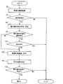
本実施形態の操作器30は、図2に示す外観を備える。図2に示すように、操作器30は、基板31と、把持部32と、突き出し板部33とを備える。把持部32は円柱形状であり、把持部32の直径は、乗員が把持部32を掴みやすい大きさになっている。また、把持部32は、高さが直径よりも小さい。通常、回転操作する部材は、高さが直径よりも小さいことから、把持部32の高さが直径よりも小さくなっていることにより、乗員は、操作器30が回転操作する部材であることを容易に認識できる。
The
突き出し板部33は、把持部32の下部から把持部32の径方向に突き出す円環板状部材である。把持部32と突き出し板部33は一体化されており、これら把持部32と突き出し板部33は、把持部32の軸心を回転中心として、基板31に対して相対回転できる。
The
また、突き出し板部33の表面には、周方向に一定間隔で複数の丸印34が表されている。図2には、3つの丸印34しか示されていないが、本実施形態の突き出し板部33は、その周方向に等間隔に4つの丸印34が表されているものとする。この丸印34は、操作器30の操作量を検出するための目印記号であるとともに、操作器30を他の部材と区別するための識別記号でもある。このような外観形状を有する本実施形態の操作器30は、電子部品は備えていない。したがって、電子部品を作動させるための電池も備えていない。
In addition, a plurality of
電子機器操作システム1、空調装置40、窓開閉装置50の構成を、図3を用いて詳しく説明する。操作検出装置10は、記憶部11と、コンピュータ12を備える。
The configuration of the electronic
記憶部11には、操作器30における目印記号および識別記号である丸印34の形状、大きさが記憶されている。
The storage unit 11 stores the shape and size of the
コンピュータ12は、CPU、ROM、RAMなどを備える。そのCPUが、RAMの記憶機能を利用しつつ、ROMに記憶されているプログラムを実行することで、コンピュータ12は、位置決定部121、走行判定部122、機能決定部123、操作判定部124、操作量決定部125、操作量信号出力部126として機能する。なお、これらの各部の一部または全部を、一つあるいは複数のIC等によりハードウェア的に構成してもよい。
The
位置決定部121は、車室内画像を解析して、操作器30の位置および操作器30のユーザである乗員の手の位置を逐次決定する。なお、手とは、手首よりも先の部分であり、腕は、本実施形態では手に含まない。この位置決定部121は、請求項の第1位置決定部および第2位置決定部として機能している。
The
操作器30の位置の決定は、記憶部11に記憶している丸印34を車室内画像から探すことにより行う。本実施形態では、正確に操作器30の位置を決定する必要はないので、丸印34の位置を操作器30の位置とすればよい。複数の丸印34が検出できたときは、たとえば、複数の丸印34の重心位置を操作器30の位置とする。
The position of the
乗員の手の位置の決定は、一般物体認識の分野で知られている種々の手法を用いて行うことができる。たとえば、車室内画像から局所画像を切り出し、局所画像に対してBof(Bag-of-features)法を適用することにより、手の位置を決定する。 The position of the passenger's hand can be determined using various methods known in the field of general object recognition. For example, the position of the hand is determined by cutting out a local image from the vehicle interior image and applying a Bof (Bag-of-features) method to the local image.
走行判定部122には、車両100の車速を表す車速信号が供給される。この車速信号に基づいて、走行判定部122は、車両100が走行状態にあるか停止状態にあるかを逐次判定する。なお、車速信号に加えてシフト位置も用いて車両100が走行状態にあるか停止状態にあるかを判定してもよい。
The traveling
機能決定部123は、位置決定部121が決定した操作器30の位置と、走行判定部122の判定結果とに基づいて、操作器30の機能をオンとするかオフとするかを決定する。操作器30の機能がオンである状態とは、操作器30が操作されたことにより、操作量信号出力部126から操作量信号が出力される状態をいう。
The
さらに機能決定部123は、操作器30の機能をオンにすると決定した場合には、操作器30により制御する電子機器(以下、制御対象機器)を決定する。制御対象機器は、位置決定部121が決定した操作器30の位置に基づいて決定する。操作器30の位置と電子機器との対応は予め設定されている。たとえば、操作器30が車両ドアから一定範囲内あれば、制御対象機器は窓開閉装置50であるとする。操作器30の位置が車両ドアから一定範囲外であれば、制御対象機器は空調装置40であるとする。
Further, when it is determined that the function of the
操作判定部124は、位置決定部121が決定した操作器30の位置と乗員の手の位置とから、乗員の手が操作器30に触れているか否かを判定する。ただし、機能決定部123が、操作器30の機能をオフにすると決定している場合には、この判定は行わない。
The
操作量決定部125は、操作判定部124が、乗員の手が操作器30に触れていると判定している場合に、乗員の手により操作器30に対して行われた操作量を決定する。この操作量の決定には車室内画像を用いる。車室内画像を逐次解析することで、操作器30の位置の変化を決定する。
The operation
本実施形態のように、操作器30に対する操作が回転操作である場合、操作器30の位置の変化は回転位置の変化である。また、操作器30には、把持部32から突き出す突き出し板部33を備えており、この突き出し板部33には丸印34が表されている。本実施形態の操作量決定部125は、丸印34の位置変化を決定し、この位置変化から突き出し板部33の回転移動量を決定する。この突き出し板部33の回転移動量を操作器30の回転移動量とする。この操作器30の回転移動量が操作量である。
When the operation on the
操作量信号出力部126は、操作量決定部125が決定した操作量に基づいて操作量信号を生成する。そして、生成した操作量信号を、機能決定部123が決定した制御対象機器の制御部、すなわち、本実施形態では空調装置40および窓開閉装置50のいずれかの制御部46、54に出力する。
The operation amount
空調装置40は、操作部42、温度センサ44、制御部46、駆動部48などを備え、車室110内の温度を調整する。操作部42は、制御部46に対して、オン、オフや設定温度を指示するために乗員が操作する部分である。操作部42が乗員により操作されると、その操作に応じた信号が制御部46に出力される。温度センサ44は、車室110内の温度を検出して、その温度を表す信号を制御部46に逐次出力する。
The
制御部46には、操作部42および温度センサ44からの信号に加えて、操作量信号出力部126から操作量信号も入力される。そして、制御部46は、操作部42から入力される信号あるいは操作量信号出力部126から入力される操作量信号に基づいて設定温度を決定し、その設定温度になるように、駆動部48のオンオフや、駆動部48の出力を決定する。駆動部48は、制御部46により制御されて、車室内の温度を上下させる。
In addition to signals from the
窓開閉装置50は、操作部52、制御部54、駆動部56などを備え、車両100の窓を開閉させる。操作部52は、車両ドアの車室110側の側面に設けられており、車両ドアを開閉させる際に乗員が操作する部分である。操作部52が乗員により操作されると、その操作に応じた信号が制御部54に出力される。
The window opening /
制御部54には、操作部52からの信号に加えて、操作量信号出力部126から操作量信号も入力される。そして、操作部52から入力される信号あるいは操作量信号出力部126から入力される操作量信号に基づいて、駆動部56の駆動量を決定し、決定した駆動量に応じた駆動信号を駆動部56に出力する。駆動部56は、モータを備えており、駆動信号に応じてモータを駆動させることで、車両ドアの窓を開閉させる。
In addition to the signal from the
次に、操作検出装置10のコンピュータ12が実行する処理を図4、図5のフローチャートを用いて説明する。操作検出装置10のコンピュータ12は、図4、図5の処理を車両100の電源がオンである間、周期的に実行する。
Next, processing executed by the
図4のステップS2では、車室内画像をカメラ20から取得する。ステップS4では、ステップS2で取得した車室内画像を解析して、操作器30を検出できたか否かを判断する。操作器30の検出は、前述のように、操作器30に表されている丸印34を車室内画像から検出することにより行う。操作器30が検出できない場合には(S4:NO)、図4の処理を終了する。操作器30が検出できた場合には(S4:YES)、ステップS6に進む。
In step S <b> 2 of FIG. 4, a vehicle interior image is acquired from the
ステップS6では、車室内画像の解析結果から、操作器30の位置を決定し、決定した位置を記憶部11に記憶する。ここまでのステップS2〜S6は、位置決定部121が行う。
In step S <b> 6, the position of the operating
ステップS8では、ステップS6で決定した操作器30の位置が運転席であるか否かを判断する。このステップS8は機能決定部123が行う。ステップS8の判断がYESであればステップS10に進む。
In step S8, it is determined whether or not the position of the operating
ステップS10では、車両100が走行中か否かを判断する。このステップS10は走行判定部122が行う。ステップS10の判断がYESであれば、図4の処理を終了する。したがって、操作器30が運転席にあり、車両100が走行中であれば、操作器30の機能はオフになり、操作器30を操作しても、操作検出装置10は操作量信号を空調装置40や窓開閉装置50に送信しないことになる。このステップS10の判断がNOであれば、ステップS12に進む。
In step S10, it is determined whether or not the
ステップS12では、操作器30の機能をオンにすると決定する。さらに、ステップS6で決定した操作器30の位置に基づいて、制御対象機器を決定する。このステップS12は機能決定部123が行う。
In step S12, it is determined that the function of the
ステップS14では、ステップS2で取得した車室内画像を解析して、乗員の手の位置を決定する。このステップS12は位置決定部121が行う。
In step S14, the vehicle interior image acquired in step S2 is analyzed to determine the position of the passenger's hand. This
ステップS16では、ステップS6で決定した操作器30の位置に、ステップS14で決定した乗員の手の位置があるか否かを判断する。このステップS16は操作判定部124が行う。操作器30の位置に乗員の手の位置がないと判断した場合には(S16:NO)、図4の処理を終了する。操作器30の位置に乗員の手の位置があると判断した場合には(S16:YES)、図5に進む。
In step S16, it is determined whether or not the position of the occupant's hand determined in step S14 is at the position of the operating
図5において、ステップS20では、再び、車室内画像をカメラ20から取得する。ステップS22では、ステップS20で取得した車室内画像を解析して、乗員の手の位置を決定する。これらステップS20、S22は位置決定部121が行う。
In FIG. 5, in step S <b> 20, the vehicle interior image is acquired again from the
ステップS24では、今回のステップS22で決定した乗員の手の位置が、図4のステップS6で決定した操作器30の位置にあるか否かを判断する。このステップS24は操作判定部124が行う。操作器30の位置に乗員の手の位置がないと判断した場合には(S24:NO)、図5の処理を終了する。したがって、乗員の手が操作器30から離れていれば、ステップS26の処理を実行しないことになる。乗員の手が操作器30から離れている状態ではステップS26以降を実行しないので、車両100の揺れ等により操作器30が転がったときの操作器30の移動に基づいて操作量を決定してしまう恐れが低減する。
In step S24, it is determined whether or not the position of the passenger's hand determined in step S22 is the position of the operating
ステップS24の判断がYESである場合には、ステップS26に進む。ステップS26および次のステップS28は操作量決定部125が行う。ステップS26では、今回のステップS20で取得した車室内画像を解析して、丸印34の位置を決定し、決定した位置をコンピュータ12のRAMあるいは記憶部11に記憶する。
If the determination in step S24 is yes, the process proceeds to step S26. The operation
続くステップS28では、乗員の手により操作器30に対して行われた操作量を決定する。操作量の決定には、前回のステップS26で決定した丸印34の車室内画像における位置、今回のステップS26で決定した丸印34の車室内画像における位置、車室内画像における丸印34の回転半径から求める。
In the subsequent step S28, the amount of operation performed on the operating
車室内画像における丸印34の回転半径としては、車室内画像における突き出し板部33の半径の値を用いる。あるいは、車室内画像における突き出し板部33の半径に1よりも少し小さい予め設定されている係数、たとえば0.9を乗じた値を、車室内画像における丸印34の回転半径とする。このようにして求めた丸印34の回転半径から、丸印34が一回転したときの車室内画像における丸印34の移動長さを求める。車室内画像における突き出し板部33の半径は、車室内画像における突き出し板部33の外周縁の形状から算出する。
As the radius of rotation of the
また、前回のステップS26で決定した丸印34の車室内画像における位置と、今回のステップS26で決定した丸印34の車室内画像における位置とから、車室内画像における丸印34の移動長さを求める。この移動長さは、車室内画像における丸印34の回転半径の円上を丸印34が移動しているとして求める。
Further, the moving length of the
そして、把持部32が一回転したときの車室内画像における丸印34の移動長さに対する、車室内画像における丸印34の移動長さの比を算出する。この比は、操作器30の回転角度を意味する。この回転角度が操作量である。
Then, the ratio of the movement length of the
続くステップS30、S32は操作量信号出力部126が行う。ステップS30では、ステップS28で決定した操作量、すなわち、操作器30の回転角度に、予め設定された換算係数を乗じることで、操作量信号を決定する。たとえば、操作器30が1回転したときの操作量信号を6とするのであれば、換算係数は6となる。また、丸印34の位置が移動していないときは、操作量信号は0となる。
The operation amount
続くステップS32では、ステップS30で生成した操作量信号を、図4のステップS12で決定した制御対象機器の制御部に出力する。ステップS32を実行した後は、ステップS20に戻る。操作器30に乗員の手が触れている状態が継続している間は、図5の処理が繰り返し実行されて、操作量信号が継続的に出力され、操作器30から乗員の手が離れると、図5の処理を終了し、一定時間後に図4の処理を開始する。
In subsequent step S32, the operation amount signal generated in step S30 is output to the control unit of the control target device determined in step S12 of FIG. After executing Step S32, the process returns to Step S20. While the state in which the occupant's hand is touching the
以上、説明した本実施形態では、操作量決定部125は、操作器30に対して乗員の手により行われた操作量を、カメラ20が撮像した車室内画像に基づいて決定する(S26、S28)。このようにして操作量を決定しているので、操作器30は、操作量信号を送信する信号送信部を備えていない。また、形状も種々の形状とすることができる。したがって、操作器に対する制限が少ない。なお、操作器の形状の別例は後述する。
As described above, in the present embodiment described above, the operation
さらに、操作器30はカメラ20で認識できる位置であれば配置位置も自由である。また、操作器30は、電子部品や電子部品を作動させるための電池を備えていないので、製造コストが安価になる。
Furthermore, the
このような単純な構造の操作器30であるが、この操作器30があることにより、乗員の操作は、操作器30を持って行う操作に限定される。これにより、乗員は、何もないところで手により操作量を示すよりも操作が行いやすい。また、操作量決定部125が決定する操作量の精度も向上する。
Although the
また、本実施形態の操作器30は、把持部32に加えて、把持部32から径方向に突き出し、把持部32と一体回転する突き出し板部33を備えている。把持部32を乗員が掴んだ状態でも、突き出し板部33は、乗員の手によって隠されずに、車室内画像に写っている可能性が高い。そして、操作量決定部125は、突き出し板部33の回転移動量を操作器30の回転移動量として決定するので、操作器30の回転移動量を決定できない場合が少なくなる。
In addition to the
さらに、操作量決定部125は、突き出し板部33に表されている丸印34の位置の変化から、突き出し板部33の回転移動量を検出する(S26、S28)。丸印34は、突き出し板部33の周方向に4つ表されており、操作器30の回転に伴い位置が変化する。したがって、丸印34の位置の変化をもとにすることにより、突き出し板部33の回転移動量を容易に検出することができる。
Further, the operation
また、本実施形態では、操作判定部124を備えており、乗員の手が操作器30に触れていないと判定した場合には(S24:NO)、操作量を決定しない。したがって、乗員が操作していない状態での操作器30の移動に基づいて操作量を決定してしまう恐れが低減する。
Moreover, in this embodiment, the
また、本実施形態では、カメラ20で操作器30の操作量を決定するという特徴を利用して、操作器30の位置も決定している。そして、操作器30の位置に基づいて、操作器30の機能のオン、オフを決定している。すなわち、操作器30の位置が運転席でなければ、車両100が走行中であるかどうかによらず、操作器30の機能をオンにしている(S8:NO)。したがって、運転者以外の乗員は、車両100が走行中でも、操作器30を操作して、制御対象機器を制御することができる。
In the present embodiment, the position of the
これに対して、操作器30が運転席にあり(S8:YES)、かつ、車両100が走行中であれば(S10:YES)、操作器30の機能はオフになるので、運転者に対しては走行強制を実施できる。
On the other hand, if the operating
さらに、操作器30の位置に基づいて操作器30の機能のオンオフを行うだけでなく、操作器30の位置に基づいて制御対象機器も決定しているので、1つの操作器30により、複数の制御対象機器を制御することができる。
Furthermore, not only the function of the operating
以上、本発明の実施形態を説明したが、本発明は上述の実施形態に限定されるものではなく、次の変形例も本発明の技術的範囲に含まれ、さらに、下記以外にも要旨を逸脱しない範囲内で種々変更して実施できる。なお、以下の説明において、それまでに使用した符号と同一番号の符号を有する要素は、特に言及する場合を除き、それ以前の実施形態における同一符号の要素と同一である。また、構成の一部のみを説明している場合、構成の他の部分については先に説明した実施形態を適用できる。 As mentioned above, although embodiment of this invention was described, this invention is not limited to the above-mentioned embodiment, The following modification is also contained in the technical scope of this invention, Furthermore, the summary other than the following is also included. Various modifications can be made without departing from the scope. In the following description, elements having the same reference numerals as those used so far are the same as the elements having the same reference numerals in the previous embodiments unless otherwise specified. Further, when only a part of the configuration is described, the above-described embodiment can be applied to the other parts of the configuration.
<変形例1>
変形例1では、図6に示すように、ステップS24がYESである場合、図5のステップS26に代えて、ステップS27を実行する。ステップS27は操作量決定部125が実行する。
<
In
ステップS27では、今回のステップS20で取得した車室内画像を解析して、操作器30に触れている乗員の手の指の位置を決定する。指の位置は、車室内画像を解析して決定できる全ての指に対して決定する。
In step S27, the vehicle interior image acquired in step S20 of this time is analyzed, and the position of the finger of the occupant's hand touching the operating
ステップS29では、前回のステップS27で決定した乗員の指の位置に対する、今回のステップS27で決定した乗員の指の位置の変化から、乗員の手により操作器30に対して行われた操作量を決定する。
In step S29, the amount of operation performed on the operating
<変形例2>
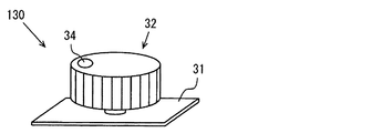
前述の実施形態の操作器30は、突き出し板部33を備えていたが、図7に示す操作器130のように、把持部32は備えているが、突き出し板部33を備えていない操作器130でもよい。なお、この操作器130は、把持部32の上面に丸印34が設けられている。把持部32の上面に丸印34が設けられている場合、乗員が把持部32を掴んだ状態では、丸印34は乗員の手に隠れてしまい、車室内画像に丸印34が写っていない可能性が高い。したがって、丸印34は、回転移動量を検出するための目印記号としては機能しない。しかし、乗員が把持部32を掴んでいなければ、車室内画像に操作器130が写っている状態では、丸印34も車室内画像に写っている可能性が十分にある。したがって、変形例1でも、丸印34は、操作器130を他の部材と区別するための識別記号としては機能する。
<Modification 2>
The operating
<変形例3>
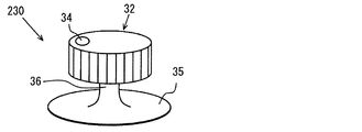
図8に示す操作器230のように、把持部32と、吸盤35と、それら把持部32と吸盤35とを連結する連結部36を備えている操作器230を用いることもできる。
<Modification 3>
As with the
<変形例4>
図9に示す操作器330は、長方形状の板状部材である。この操作器330は、長手方向の両側に二次元情報コード331が表されている。この操作器330に対する操作はタップ操作であり、ユーザは、操作器330を手に持って、二次元情報コード331の部分をタップする。操作量決定部125は、タップ操作の回数を操作量とする。また、左右の二次元情報コード331を区別してタップ操作の回数を決定してもよい。
<Modification 4>
The operating
二次元情報コード331には、この二次元情報コード331が表された部材が操作器330であることがコード化されて格納されており、操作器330を他の部材と区別するための識別記号として機能する。位置決定部121は、二次元情報コード331を読み取って操作器330であると判定した場合に、二次元情報コード331の位置、あるいは、二次元情報コード331がある部材の位置を、操作器330の位置とする。
In the two-
操作器330は、二次元情報コード331がない場合には単なる板であり、他にも形状が似た部材が周囲に存在する可能性がある。しかし、二次元情報コード331を備えることにより、位置決定部121は、他の部材の位置を、操作器330の位置と誤認識してしまうことを抑制できる。
The
なお、二次元情報コードに代えて、一次元情報コードを用いることもできる。そして、情報コードを用いる場合には、情報コードを表したシールを製造し、ユーザが所望の部材にシールを貼り付ければ、任意の部材を操作器とすることができる。また、情報コードでなくても、他の部材と区別することができる識別記号であれば、その識別記号を表したシールを製造すれば、情報コードを表したシールと同様、任意の部材を操作器とすることができる。 Note that a one-dimensional information code may be used instead of the two-dimensional information code. And when using an information code, if the seal | sticker showing the information code is manufactured and a user affixes a seal | sticker on a desired member, arbitrary members can be used as an operating device. In addition, even if it is not an information code, if it is an identification symbol that can be distinguished from other members, if a seal representing the identification symbol is manufactured, any member can be operated in the same manner as a seal representing the information code. Can be a container.
<変形例5>
図10に示す操作器430は、長方形の板状の基板431と、角柱形の把持部433を備えている。基板431には、長手方向にレール432が形成されている。把持部433はレール432に沿って、基板431の長手方向に移動する。この操作器430のように、操作器430の位置の変化、より正確には操作器430の一部材である把持部433の位置の変化は、平行移動であってもよい。
<Modification 5>
The
<変形例6>
図11の操作器530は、円柱形状の基部531と操作部533を備えている。操作部533の直径は、基部531の直径よりも小さくなっており、基部531に設けられた収容穴532に、操作部533の下側の一部が収容される。そして、操作部533と、収容穴532の底面との間に設けられたバネにより、操作部533は、基部531に対して上下方向に移動する。この操作器530においては、操作器530の位置の変化は、基部531に対する操作部533の位置の変化であり、操作量は、操作部533が押された回数である。
<Modification 6>
The
<変形例7、8>
変形例4で示した操作器330を用い、操作器330の角度が変化する操作に基づいて、操作量を決定してもよい。たとえば、操作器330の長手方向両端をそれぞれ左右の手で持って、操作器330の一方の端を、他方の端に対して上下させる操作に基づいて、操作量を決定してもよい(変形例7)。
<Modifications 7 and 8>
Using the
また、ジョイスティックのように、ある基台から棒状部材が突き出した操作器を用いることもできる(変形例8)。 Further, an operating device in which a rod-like member protrudes from a certain base, such as a joystick, can be used (Modification 8).
<変形例9>
前述の実施形態では、操作器30は移動量を検出するために、目印記号として丸印34を備えていたが、操作器が目印記号を備えず、操作器自体の移動量を検出してもよい。
<Modification 9>
In the above-described embodiment, the
<変形例10、11>
前述の実施形態の操作器30は、複数の電子機器を操作できるようになっていたが、一つの電子機器のみを操作できるようになっていてもよい。この場合において、複数の電子機器にそれぞれ対応した複数の操作器を用意してもよい(変形例10)。
<
Although the
また、操作器30により複数の電子機器を操作できるようになっている場合でも、制御対象機器の決定方法は前述の実施形態の態様に限られない。たとえば、車室110内に備えられた表示器に制御対象機器の候補を表示し、乗員の操作により、1つの制御対象機器を決定するようにしてもよい(変形例11)。このようにすれば、乗員は、カメラ20が操作器30を認識できる位置であれば、乗員の好きな位置で操作器30を操作して制御対象機器を制御することができる。
Further, even when a plurality of electronic devices can be operated by the
<変形例12>
前述の実施形態では、操作器30の位置が運転席にあり(S8:YES)、走行中であれば(S10:YES)、図4の処理を終了、すなわち、操作器30による操作を受け付けないことにしていた。しかし、ステップS10がYESになった場合にも、操作器30による操作を受け付ける状態としてもよい。
<
In the above-described embodiment, if the position of the
なお、操作器30の位置が運転席にあり、車両100が走行中である状態で操作器30による操作を受け付ける場合、操作器30を操作して行うことができる制御を、操作器30が運転席にない場合や走行中でない場合よりも制限してもよい。一例としては、操作器30が運転席にあり、車両100が走行中である状態では、操作器30を操作して行うことができる制御を、音量の調整など、画面を見ないで調整できる制御に限定する例がある。
In addition, when the position of the operating
<変形例13>
前述の実施形態の電子機器操作システム1は車両100で用いられていたが、建物内で電子機器操作システム1を用いることもできる。
<Modification 13>
Although the electronic
<変形例14>
操作検出装置10は、制御対象機器とは別の装置であったが、制御対象機器が操作検出装置10としての機能を備えていてもよい。
<Modification 14>
The
1:電子機器操作システム、 10:操作検出装置、 11:記憶部、 12:コンピュータ、 20:カメラ、 30:操作器、 31:基板、 32:把持部、 33:突き出し板部、 34:丸印、 35:吸盤、 36:連結部、 40:空調装置、 46:制御部、 50:窓開閉装置、 54:制御部、 100:車両、 110:車室、 121:位置決定部、 122:走行判定部、 123:機能決定部、 124:操作判定部、 125:操作量決定部、 126:操作量信号出力部、 130:操作器、 230:操作器、 330:操作器、 331:二次元情報コード、 430:操作器、 530:操作器 DESCRIPTION OF SYMBOLS 1: Electronic device operation system, 10: Operation detection apparatus, 11: Memory | storage part, 12: Computer, 20: Camera, 30: Controller, 31: Board | substrate, 32: Gripping part, 33: Extrusion board part, 34: Circle mark , 35: suction cup, 36: connecting unit, 40: air conditioner, 46: control unit, 50: window opening / closing device, 54: control unit, 100: vehicle, 110: vehicle compartment, 121: position determining unit, 122: traveling determination Unit: 123: function determination unit 124: operation determination unit 125: operation amount determination unit 126: operation amount signal output unit 130: operation unit 230: operation unit 330: operation unit 331: two-dimensional information code 430: Controller, 530: Controller
Claims (6)
カメラ(20)と、
前記操作器の位置の変化を伴う操作、および、前記操作器に対するタップ操作の少なくともいずれかが、ユーザの手により行われたことによる操作量を、前記カメラが撮像した画像に基づいて決定する操作量決定部(125)と、
前記操作量決定部が決定した前記操作量に基づいて前記操作量信号を決定して、決定した前記操作量信号を前記制御部に対して出力する操作量信号出力部(126)と、
前記カメラが撮像した画像に基づいて、前記操作器の位置を決定する第2位置決定部(121)と、
前記第2位置決定部が決定した前記操作器の位置に基づいて、前記操作器の機能を決定する機能決定部(123)とを備え、
前記電子機器操作システムは車両で用いられ、
前記車両が走行状態であるか否かを逐次判定する走行判定部(122)を備え、
前記カメラは、前記車両の車室内の運転席および運転席以外の少なくとも一つの座席を撮像範囲としており、
前記機能決定部は、
前記走行判定部が走行状態であると判定しており、且つ、前記第2位置決定部が、前記操作器が前記運転席にあると決定している場合には、前記操作器の機能をオフにし、
前記走行判定部が走行状態でないと判定している場合、または、前記走行判定部が走行状態であると判定しているが、前記第2位置決定部が、前記操作器が前記運転席にないと決定している場合には、前記操作器の機能をオンにすることを特徴とする電子機器操作システム。 An electronic device (40, 50) provided with a control unit (46, 54) that performs control based on an operation amount signal representing an operation amount performed on the operation device (30, 130, 230, 330, 430, 530). ) Operating system (1) for operating
A camera (20);
An operation for determining an operation amount when at least one of an operation accompanied by a change in the position of the operation device and a tap operation on the operation device is performed by a user's hand based on an image captured by the camera. An amount determination unit (125);
An operation amount signal output unit (126) that determines the operation amount signal based on the operation amount determined by the operation amount determination unit, and outputs the determined operation amount signal to the control unit;
A second position determination unit (121) for determining a position of the operation device based on an image captured by the camera;
A function determining unit (123) for determining a function of the operating device based on the position of the operating device determined by the second position determining unit;
The electronic device operating system is used in a vehicle,
A traveling determination unit (122) for sequentially determining whether or not the vehicle is in a traveling state;
The camera has at least one seat other than the driver's seat and the driver's seat in the passenger compartment of the vehicle as an imaging range,
The function determining unit
When the travel determination unit determines that the vehicle is in a traveling state and the second position determination unit determines that the operation device is in the driver's seat, the function of the operation device is turned off. West,
When the traveling determination unit determines that the traveling state is not in a traveling state or when the traveling determination unit determines that the traveling state is in a traveling state, the second position determination unit is not in the driver's seat. If it is determined, the electronic device operation system is characterized in that the function of the operation device is turned on .
前記操作量決定部は、前記操作器に対して、前記操作器の位置の変化を伴う操作が前記ユーザの手により行われたことによる操作量を決定するものであり、前記操作器の移動量を検出し、検出した移動量を前記操作量とすることを特徴とする電子機器操作システム。 In claim 1,
The operation amount determination unit is configured to determine an operation amount when an operation accompanied by a change in the position of the operation device is performed by the user's hand with respect to the operation device, and a movement amount of the operation device , And the detected movement amount is used as the operation amount.
前記操作器(30)を備え、
前記操作器は、
円柱形状であって、前記ユーザの手により把持されて回転移動させられる把持部(32)と、
前記把持部と一体回転し、前記把持部の下部から前記把持部の径方向に突き出す板状の突き出し板部(33)とを備え、
前記操作量決定部は、前記操作器の回転移動量を前記操作量として決定するものであって、前記操作器の突き出し板部の回転移動量を、前記操作器の回転移動量とすることを特徴とする電子機器操作システム。 In claim 2,
Comprising the operating device (30);
The controller is
A grip portion (32) that is cylindrical in shape and is gripped and rotated by the user's hand;
A plate-like protruding plate portion (33) that rotates integrally with the holding portion and protrudes in a radial direction of the holding portion from a lower portion of the holding portion;
The operation amount determination unit determines a rotation movement amount of the operation device as the operation amount, and sets a rotation movement amount of the protruding plate portion of the operation device as a rotation movement amount of the operation device. Electronic device operation system characterized.
前記突き出し板部の表面に、前記突き出し板部の回転により位置が変化する目印記号(34)が複数備えられ、
前記操作量決定部は、前記目印記号の位置変化に基づいて、前記操作器の回転移動量を検出することを特徴とする電子機器操作システム。 In claim 3,
A plurality of mark symbols (34) whose positions are changed by rotation of the protruding plate portion are provided on the surface of the protruding plate portion,
The electronic device operation system, wherein the operation amount determination unit detects a rotational movement amount of the operation device based on a change in position of the mark symbol.
前記操作量決定部は、前記操作器に対して、前記操作器の位置の変化を伴う操作が前記ユーザの手により行われたことによる操作量を決定するものであり、前記ユーザの手の移動量を検出し、検出した移動量に基づいて前記操作量を決定することを特徴とする電子機器操作システム。 In claim 1,
The operation amount determination unit is configured to determine an operation amount when an operation involving a change in the position of the operation device is performed by the user's hand with respect to the operation device, and movement of the user's hand An electronic device operation system, wherein an operation amount is detected and the operation amount is determined based on the detected movement amount.
前記電子機器操作システムは、1つの前記操作器により、複数の前記電子機器を制御するものであり、
前記機能決定部は、前記操作器の位置に基づいて、前記操作器により制御する前記電子機器を決定することを特徴とする電子機器操作システム。
In any one of Claims 1-5 ,
The electronic device operating system is for controlling a plurality of the electronic devices with one operating device,
The function determining unit determines the electronic device to be controlled by the operating device based on the position of the operating device.
Priority Applications (2)
| Application Number | Priority Date | Filing Date | Title |
|---|---|---|---|
| JP2014133118A JP6252380B2 (en) | 2014-06-27 | 2014-06-27 | Electronic equipment operation system |
| PCT/JP2015/003057 WO2015198565A1 (en) | 2014-06-27 | 2015-06-18 | Electronic equipment operation system |
Applications Claiming Priority (1)
| Application Number | Priority Date | Filing Date | Title |
|---|---|---|---|
| JP2014133118A JP6252380B2 (en) | 2014-06-27 | 2014-06-27 | Electronic equipment operation system |
Publications (3)
| Publication Number | Publication Date |
|---|---|
| JP2016011029A JP2016011029A (en) | 2016-01-21 |
| JP2016011029A5 JP2016011029A5 (en) | 2016-06-30 |
| JP6252380B2 true JP6252380B2 (en) | 2017-12-27 |
Family
ID=54937673
Family Applications (1)
| Application Number | Title | Priority Date | Filing Date |
|---|---|---|---|
| JP2014133118A Expired - Fee Related JP6252380B2 (en) | 2014-06-27 | 2014-06-27 | Electronic equipment operation system |
Country Status (2)
| Country | Link |
|---|---|
| JP (1) | JP6252380B2 (en) |
| WO (1) | WO2015198565A1 (en) |
Families Citing this family (2)
| Publication number | Priority date | Publication date | Assignee | Title |
|---|---|---|---|---|
| JP7188289B2 (en) * | 2019-06-24 | 2022-12-13 | 株式会社豊田自動織機 | battery-powered industrial vehicle |
| JP7443955B2 (en) | 2020-06-24 | 2024-03-06 | コベルコ建機株式会社 | Work machines, work support systems |
Family Cites Families (5)
| Publication number | Priority date | Publication date | Assignee | Title |
|---|---|---|---|---|
| JP2593130Y2 (en) * | 1993-05-31 | 1999-04-05 | 日本開閉器工業株式会社 | Compound operation type switch |
| US6175610B1 (en) * | 1998-02-11 | 2001-01-16 | Siemens Aktiengesellschaft | Medical technical system controlled by vision-detected operator activity |
| JP2000006687A (en) * | 1998-06-25 | 2000-01-11 | Yazaki Corp | Onboard equipment switch safety operation system |
| JP2001143559A (en) * | 1999-11-15 | 2001-05-25 | Auto Network Gijutsu Kenkyusho:Kk | On-board driving device |
| JP2011116286A (en) * | 2009-12-04 | 2011-06-16 | Toyota Motor Corp | System for operating on-board equipment |
-
2014
- 2014-06-27 JP JP2014133118A patent/JP6252380B2/en not_active Expired - Fee Related
-
2015
- 2015-06-18 WO PCT/JP2015/003057 patent/WO2015198565A1/en active Application Filing
Also Published As
| Publication number | Publication date |
|---|---|
| JP2016011029A (en) | 2016-01-21 |
| WO2015198565A1 (en) | 2015-12-30 |
Similar Documents
| Publication | Publication Date | Title |
|---|---|---|
| KR101550604B1 (en) | Vehicle operation device | |
| US10417510B2 (en) | System, methods, and apparatus for in-vehicle fiducial mark tracking and interpretation | |
| EP2862125B1 (en) | Depth based context identification | |
| US7289645B2 (en) | Hand pattern switch device | |
| CN109313487B (en) | Object controller | |
| US8498745B2 (en) | Robot apparatus and gripping method for use in robot apparatus | |
| KR101665554B1 (en) | Control apparatus using dial, vehicle comprising the same, and control method for the vehicle | |
| CN105829993B (en) | Armband sensor and method for operating an armband sensor | |
| JP2009129171A (en) | Information processor loaded in mobile body | |
| US9757985B2 (en) | System and method for providing a gear selection indication for a vehicle | |
| JP2006285370A (en) | Hand pattern switch device and hand pattern operation method | |
| US20170230812A1 (en) | Method and system for detecting an input to a device | |
| CN110968184B (en) | Equipment control device | |
| JP6252380B2 (en) | Electronic equipment operation system | |
| KR101628482B1 (en) | System for detecting motion using analysis of radio signal in vehicel and method thereof | |
| KR101237035B1 (en) | apparatus of controlling turn signal lamp | |
| JP2018501998A (en) | System and method for controlling automotive equipment | |
| JP2006298003A (en) | Command input device | |
| US20230191617A1 (en) | Robot and control method therefor | |
| JP2006312346A (en) | Command input device | |
| Jung et al. | Communication quality analysis for remote control of a differential drive robot based on iphone interface | |
| KR20120056698A (en) | An apparatus and method using motion recognition based upon uwb communication | |
| US11656759B2 (en) | Semitransparent tactile surface sensor and a method of sensing an interaction with an object using the semitransparent tactile surface sensor | |
| KR101970872B1 (en) | Apparatus and method for analyzing driver's posture and condition | |
| KR101500413B1 (en) | Gesture recognize apparatus for vehicle |
Legal Events
| Date | Code | Title | Description |
|---|---|---|---|
| A521 | Request for written amendment filed |
Free format text: JAPANESE INTERMEDIATE CODE: A523 Effective date: 20160513 |
|
| A621 | Written request for application examination |
Free format text: JAPANESE INTERMEDIATE CODE: A621 Effective date: 20170217 |
|
| TRDD | Decision of grant or rejection written | ||
| A01 | Written decision to grant a patent or to grant a registration (utility model) |
Free format text: JAPANESE INTERMEDIATE CODE: A01 Effective date: 20171031 |
|
| A61 | First payment of annual fees (during grant procedure) |
Free format text: JAPANESE INTERMEDIATE CODE: A61 Effective date: 20171113 |
|
| R151 | Written notification of patent or utility model registration |
Ref document number: 6252380 Country of ref document: JP Free format text: JAPANESE INTERMEDIATE CODE: R151 |
|
| R250 | Receipt of annual fees |
Free format text: JAPANESE INTERMEDIATE CODE: R250 |
|
| R250 | Receipt of annual fees |
Free format text: JAPANESE INTERMEDIATE CODE: R250 |
|
| LAPS | Cancellation because of no payment of annual fees |