JP6251985B2 - Vehicle lighting - Google Patents
Vehicle lighting Download PDFInfo
- Publication number
- JP6251985B2 JP6251985B2 JP2013115349A JP2013115349A JP6251985B2 JP 6251985 B2 JP6251985 B2 JP 6251985B2 JP 2013115349 A JP2013115349 A JP 2013115349A JP 2013115349 A JP2013115349 A JP 2013115349A JP 6251985 B2 JP6251985 B2 JP 6251985B2
- Authority
- JP
- Japan
- Prior art keywords
- light
- light guide
- incident
- guide member
- light emitting
- Prior art date
- Legal status (The legal status is an assumption and is not a legal conclusion. Google has not performed a legal analysis and makes no representation as to the accuracy of the status listed.)
- Active
Links
- 238000005192 partition Methods 0.000 claims 1
- 230000003287 optical effect Effects 0.000 description 13
- 230000000694 effects Effects 0.000 description 5
- 229920003229 poly(methyl methacrylate) Polymers 0.000 description 4
- 239000004417 polycarbonate Substances 0.000 description 4
- 239000004926 polymethyl methacrylate Substances 0.000 description 4
- 230000003760 hair shine Effects 0.000 description 3
- 239000011347 resin Substances 0.000 description 3
- 229920005989 resin Polymers 0.000 description 3
- NIXOWILDQLNWCW-UHFFFAOYSA-N acrylic acid group Chemical group C(C=C)(=O)O NIXOWILDQLNWCW-UHFFFAOYSA-N 0.000 description 2
- 239000000463 material Substances 0.000 description 2
- 229910052751 metal Inorganic materials 0.000 description 2
- 239000002184 metal Substances 0.000 description 2
- 239000000113 methacrylic resin Substances 0.000 description 2
- 229920000515 polycarbonate Polymers 0.000 description 2
- 239000004065 semiconductor Substances 0.000 description 2
- 239000000758 substrate Substances 0.000 description 2
- BQCADISMDOOEFD-UHFFFAOYSA-N Silver Chemical compound [Ag] BQCADISMDOOEFD-UHFFFAOYSA-N 0.000 description 1
- 229910052782 aluminium Inorganic materials 0.000 description 1
- XAGFODPZIPBFFR-UHFFFAOYSA-N aluminium Chemical compound [Al] XAGFODPZIPBFFR-UHFFFAOYSA-N 0.000 description 1
- 239000011248 coating agent Substances 0.000 description 1
- 238000000576 coating method Methods 0.000 description 1
- 230000007423 decrease Effects 0.000 description 1
- 230000008021 deposition Effects 0.000 description 1
- 238000010586 diagram Methods 0.000 description 1
- 229910052736 halogen Inorganic materials 0.000 description 1
- 150000002367 halogens Chemical class 0.000 description 1
- 238000007747 plating Methods 0.000 description 1
- 238000007789 sealing Methods 0.000 description 1
- 229910052709 silver Inorganic materials 0.000 description 1
- 239000004332 silver Substances 0.000 description 1
- 230000037303 wrinkles Effects 0.000 description 1
Images


Classifications
-
- F—MECHANICAL ENGINEERING; LIGHTING; HEATING; WEAPONS; BLASTING
- F21—LIGHTING
- F21S—NON-PORTABLE LIGHTING DEVICES; SYSTEMS THEREOF; VEHICLE LIGHTING DEVICES SPECIALLY ADAPTED FOR VEHICLE EXTERIORS
- F21S43/00—Signalling devices specially adapted for vehicle exteriors, e.g. brake lamps, direction indicator lights or reversing lights
- F21S43/20—Signalling devices specially adapted for vehicle exteriors, e.g. brake lamps, direction indicator lights or reversing lights characterised by refractors, transparent cover plates, light guides or filters
- F21S43/235—Light guides
- F21S43/236—Light guides characterised by the shape of the light guide
- F21S43/239—Light guides characterised by the shape of the light guide plate-shaped
-
- F—MECHANICAL ENGINEERING; LIGHTING; HEATING; WEAPONS; BLASTING
- F21—LIGHTING
- F21S—NON-PORTABLE LIGHTING DEVICES; SYSTEMS THEREOF; VEHICLE LIGHTING DEVICES SPECIALLY ADAPTED FOR VEHICLE EXTERIORS
- F21S43/00—Signalling devices specially adapted for vehicle exteriors, e.g. brake lamps, direction indicator lights or reversing lights
- F21S43/20—Signalling devices specially adapted for vehicle exteriors, e.g. brake lamps, direction indicator lights or reversing lights characterised by refractors, transparent cover plates, light guides or filters
- F21S43/235—Light guides
- F21S43/236—Light guides characterised by the shape of the light guide
- F21S43/237—Light guides characterised by the shape of the light guide rod-shaped
-
- F—MECHANICAL ENGINEERING; LIGHTING; HEATING; WEAPONS; BLASTING
- F21—LIGHTING
- F21S—NON-PORTABLE LIGHTING DEVICES; SYSTEMS THEREOF; VEHICLE LIGHTING DEVICES SPECIALLY ADAPTED FOR VEHICLE EXTERIORS
- F21S43/00—Signalling devices specially adapted for vehicle exteriors, e.g. brake lamps, direction indicator lights or reversing lights
- F21S43/20—Signalling devices specially adapted for vehicle exteriors, e.g. brake lamps, direction indicator lights or reversing lights characterised by refractors, transparent cover plates, light guides or filters
- F21S43/235—Light guides
- F21S43/251—Light guides the light guides being used to transmit light from remote light sources
-
- F—MECHANICAL ENGINEERING; LIGHTING; HEATING; WEAPONS; BLASTING
- F21—LIGHTING
- F21S—NON-PORTABLE LIGHTING DEVICES; SYSTEMS THEREOF; VEHICLE LIGHTING DEVICES SPECIALLY ADAPTED FOR VEHICLE EXTERIORS
- F21S43/00—Signalling devices specially adapted for vehicle exteriors, e.g. brake lamps, direction indicator lights or reversing lights
- F21S43/10—Signalling devices specially adapted for vehicle exteriors, e.g. brake lamps, direction indicator lights or reversing lights characterised by the light source
- F21S43/13—Signalling devices specially adapted for vehicle exteriors, e.g. brake lamps, direction indicator lights or reversing lights characterised by the light source characterised by the type of light source
- F21S43/14—Light emitting diodes [LED]
Landscapes
- Engineering & Computer Science (AREA)
- General Engineering & Computer Science (AREA)
- Non-Portable Lighting Devices Or Systems Thereof (AREA)
Description
この発明は、光源と導光部材と発光部材とを使用する車両用灯具に関するものである。 The present invention relates to a vehicular lamp that uses a light source, a light guide member, and a light emitting member.
この種の車両用灯具は、従来からある(たとえば、特許文献1)。以下、従来の車両用灯具について説明する。従来の車両用灯具は、光源(LED)と、柱状導光体と、板状導光体と、を備えるものである。光源からの光は、柱状導光体の光入射端部から柱状導光体中に入射してかつ柱状導光体中を他方の端部に向けて導光される。柱状導光体中に入射した光は、柱状導光体の内面反射ステップにより柱状導光体から出射する。柱状導光体から出射した光は、板状導光体の一方の面から板状導光体中に入射してかつ板状導光体中を他方の面に向けて導光される。板状導光体中に入射した光は、板状導光体の内面反射ステップにより板状導光体の前面から出射する。これにより、板状導光体の前面が面状に発光して、たとえば、ターンシグナルランプとして機能する。 This type of vehicular lamp is conventionally known (for example, Patent Document 1). Hereinafter, a conventional vehicle lamp will be described. A conventional vehicular lamp includes a light source (LED), a columnar light guide, and a plate light guide. Light from the light source enters the columnar light guide from the light incident end of the columnar light guide and is guided through the columnar light guide toward the other end. The light incident on the columnar light guide is emitted from the columnar light guide by the internal reflection step of the columnar light guide. Light emitted from the columnar light guide enters the plate light guide from one surface of the plate light guide and is guided through the plate light guide toward the other surface. The light incident on the plate-like light guide is emitted from the front surface of the plate-like light guide by the internal reflection step of the plate-like light guide. Thereby, the front surface of the plate-like light guide emits light in a planar shape, and functions as, for example, a turn signal lamp.
ところが、従来の車両用灯具は、板状導光体中に入射した光を内面反射ステップで前面に反射させるものである。このために、従来の車両用灯具は、板状導光体の内面反射ステップが板状導光体の前面において暗部の線(スジ)として見えて見栄え上問題が有る。 However, the conventional vehicular lamp reflects light incident on the plate-like light guide to the front surface by an internal reflection step. For this reason, the conventional vehicular lamp has a problem in appearance because the internal light reflection step of the plate-like light guide appears as a dark line (streak) on the front surface of the plate-like light guide.
この発明が解決しようとする課題は、従来の車両用灯具では、板状導光体の前面において暗部の線が見える、という点にある。 The problem to be solved by the present invention is that, in the conventional vehicular lamp, a dark line can be seen on the front surface of the plate-like light guide.
この発明は、灯室を区画するランプハウジングおよびランプレンズと、灯室内に配置されている光源および導光部材および発光部材と、を備え、導光部材は、円柱形状をなし、該導光部材の両端面の一方の端面に設けられて、光源からの光を導光部材中に入射させる入射面と、導光部材の側面のうちの一部であって、導光部材の両端面の間に設けられて、入射面から導光部材中に入射した入射光を反射させる反射面と、導光部材の側面のうちの一部であって、導光部材の両端面の間に、反射面と対向して設けられて、反射面により反射された反射光を外部に出射させる出射面と、を有し、発光部材が、板形状をなし、導光部材の出射面と対向していて導光部材の出射面から出射した出射光を発光部材中に入射させる入射面と、発光部材の入射面と対向して設けられていて入射面から発光部材中に入射した入射光を外部に出射させる出射面と、を有し、反射面は、導光部材の軸方向に並ぶ多数の反射面と、該反射面と反射面との間に設けられる多数の傾斜面とを有する多数のプリズムから構成され、導光部材の一方の端面の入射面から他方の端面に向かうに従って、プリズムの山部に設ける平面が高くなる、もしくは、プリズムの谷部に設ける平面が低くなる構造を有し、導光部材中に入射した入射光を導光部材の出射面側に均一もしくはほぼ均一に反射させる反射面である、ことを特徴とする。 The inventions includes a lamp housing and a lamp lens defining the lamp chamber, a light source and the light guide member and the light emitting member is disposed in the lamp chamber, the light guide member is in the form a cylindrical shape, the light guide An incident surface provided on one end surface of the both end surfaces of the member and allowing light from the light source to enter the light guide member, and a part of the side surfaces of the light guide member, A reflection surface provided between the reflection surface that reflects incident light that has entered the light guide member from the incident surface and a part of the side surface of the light guide member that is reflected between both end surfaces of the light guide member The light emitting member has a plate shape and is opposed to the light exiting surface of the light guide member. Incident surface for entering the light emitted from the light exiting surface of the light guide member into the light emitting member, and the incident of the light emitting member A counterflow provided by to have a, an exit surface for emitting to the outside the light incident in the light-emitting member from the incident surface, the reflective surface, a plurality of reflecting surfaces arranged in the axial direction of the light guide member, It is composed of a large number of prisms having a large number of inclined surfaces provided between the reflecting surface and the reflecting surface, and is provided at the peak portion of the prism as it goes from the incident surface on one end surface of the light guide member to the other end surface. A reflective surface that has a structure in which the flat surface is high or the flat surface provided in the valley of the prism is low, and reflects incident light incident on the light guide member uniformly or almost uniformly on the light exit surface side of the light guide member. It is characterized by that.
この発明は、板形状をなす発光部材の入射面の高さが、円柱形状をなす導光部材の直径と同等もしくはほぼ同等であり、板形状をなす発光部材の入射面の幅が、円柱形状をなす導光部材の両端面の間の距離と同等もしくはほぼ同等である、ことを特徴とする。 The inventions, the height of the incident surface of the light-emitting member having a plate shape, are equivalent or substantially equivalent to the diameter of the light guide member having a cylindrical shape, the width of the incident surface of the light-emitting member having a plate shape, cylindrical It is characterized by being equal to or substantially equivalent to the distance between both end faces of the light guide member having a shape.
この発明は、灯室内には、インナーパネルがランプレンズと対向して配置されていて、インナーパネルには、発光部材が挿通されていて、光源および導光部材および発光部材の入射面が、インナーパネルよりランプハウジング側に配置されていて、発光部材の出射面が、インナーパネルよりランプレンズ側にランプレンズと対向して配置されている、ことを特徴とする。 The inventions is the lamp chamber, the inner panel has been arranged to face the lamp lens, the inner panel, light emitting members have been inserted, the incident surface of the light source and the light guide member and the light emitting member, The light emitting member is disposed on the lamp housing side from the inner panel, and the emission surface of the light emitting member is disposed on the lamp lens side from the inner panel so as to face the lamp lens.
この発明は、発光部材のうち少なくともインナーパネルよりランプレンズ側に配置されている部分であって発光部材の出射面以外の面には、意匠面が施されている、ことを特徴とする。 The inventions are, on the surface other than the exit surface of the at least a light-emitting member a portion from the inner panel is disposed on the lamp lens side of the light emitting members, design surface is applied, characterized in that.
この発明の車両用灯具は、光源を点灯すると、光源からの光が導光部材の入射面から導光部材中に入射し、その入射光が導光部材の反射面で反射され、その反射光が導光部材の出射面から出射し、その出射光が発光部材の入射面から発光部材中に入射し、その入射光が発光部材の出射面から外部に出射して、発光部材の出射面が面状に発光する。このように、この発明(請求項1にかかる発明)の車両用灯具は、発光部材の入射面から入射した光を発光部材の出射面から外部に出射させるものである。このために、板状導光体中に入射した光を内面反射ステップで前面に反射させる従来の車両用灯具のように、発光部材の出射面において暗部の線が見えるようなことがない。これにより、見栄えを向上させることができる。 In the vehicular lamp according to the present invention, when the light source is turned on, light from the light source enters the light guide member from the incident surface of the light guide member, and the incident light is reflected by the reflective surface of the light guide member. Is emitted from the emission surface of the light guide member, the emitted light is incident on the light emitting member from the incident surface of the light emitting member, the incident light is emitted to the outside from the emission surface of the light emitting member, and the emission surface of the light emitting member is Emits light in a planar shape. As described above, the vehicular lamp according to the present invention (the invention according to claim 1) emits the light incident from the light incident surface of the light emitting member to the outside from the light emitting surface of the light emitting member. For this reason, unlike the conventional vehicular lamp that reflects the light incident on the plate-like light guide to the front surface by the inner surface reflection step, the dark part line is not seen on the emission surface of the light emitting member. Thereby, appearance can be improved.
以下、この発明にかかる車両用灯具の実施形態(実施例)のうちの4例を図面に基づいて詳細に説明する。なお、この実施形態によりこの発明が限定されるものではない。図1、図3〜図7の断面図において、光路を明確にするために、導光部材および発光部材のハッチングを省略してある。 Hereinafter, four examples of an embodiment (example) of a vehicular lamp according to the present invention will be described in detail with reference to the drawings. In addition, this invention is not limited by this embodiment. In the cross-sectional views of FIGS. 1 and 3 to 7, the light guide member and the light emitting member are not hatched in order to clarify the optical path.
(実施形態1の構成の説明)
図1〜図5は、この発明にかかる車両用灯具の実施形態1を示す。以下、この実施形態1における車両用灯具の構成について説明する。図中、符号1は、この実施形態1における車両用灯具である。前記車両用灯具1は、たとえば、テールランプ、クリアランスランプ、ポジションランプ、ターンシグナルランプ、ストップランプ、テール・ストップランプ、室内ランプなどの自動車用灯具である。
(Description of Configuration of Embodiment 1)
1 to 5
(車両用灯具1の説明)
前記車両用灯具1は、図1、図2、図4に示すように、ランプハウジング2と、ランプレンズ3と、1個の光源4と、導光部材(導光棒、導光体)5と、発光部材6と、インナーパネル(インナーハウジング、エクステンション、装飾部材)7と、を備えるものである。
(Description of vehicle lamp 1)
As shown in FIGS. 1, 2, and 4, the
前記ランプハウジング2および前記ランプレンズ3は、灯室8を画成する。前記灯室8内には、前記光源4および前記導光部材5および前記発光部材6および前記インナーパネル7がそれぞれ配置されている。前記光源4および前記導光部材5は、取付ブラケット9を介して前記ランプハウジング2に取り付けられている。
The
(インナーパネル7の説明)
図1に示すように、前記インナーパネル7は、前記ランプレンズ3と対向するように、前記ランプハウジング2に取り付けられている。前記インナーパネル7の少なくとも正面(前面、前記ランプレンズ3と対向する面)には、たとえば、アルミ(金属)蒸着や銀塗装や金属メッキなどが施されている。
(Description of inner panel 7)
As shown in FIG. 1, the
前記インナーパネル7には、前記発光部材6が挿通固定されている。前記光源4および前記導光部材5および前記発光部材6の入射面60は、前記インナーパネル7より前記ランプハウジング2側(前記インナーパネル7の背面(後面)側)に配置されている。前記発光部材6の出射面61は、前記インナーパネル7より前記ランプレンズ3側(前記インナーパネル7の正面側)に前記ランプレンズ3と対向して配置されている。
The
(光源4の説明)
前記光源4は、この例では、たとえば、LED、OELまたはOLED(有機EL)などの自発光半導体型光源である。前記光源4は、基板(図示せず)と、前記基板に適宜に配置されて設けられている1個もしくは複数個の発光チップ(図示せず)と、前記発光チップを封止する封止樹脂部材(図示せず)と、から構成されている。前記光源4は、コネクタ部(図示せず)を介して電源(電流)が供給される。
(Description of light source 4)
In this example, the
(導光部材5の説明)
前記導光部材5は、光を導く性質を有する部材、この例では、アクリル、PC(ポリカーボネート)、PMMA(ポリメタクリル酸メチル、メタクリル樹脂)などの透明樹脂材からなる。前記導光部材5は、図1、図3〜図5に示すように、円柱形状をなす。前記導光部材5は、入射面50と、反射面51と、出射面52と、を有する。前記導光部材5は、一端の前記入射面50から入射した入射光L1を、全反射を繰り返して他端まで導くものである(図4参照)。
(Description of the light guide member 5)
The
前記入射面50は、前記光源4からの光を前記入射光L1として前記導光部材5中に入射させる。前記入射面50は、この例では、前記導光部材5の両端面のうちの一方の端面に設けられている。1個の前記光源4は、前記導光部材5の1個の前記入射面50に対向して配置されている。なお、前記導光部材5の両端面に前記入射面50をそれぞれ設けて、2個の前記入射面50に前記光源4をそれぞれ対向して配置しても良い。この場合は、前記光源4が2個となる。
The
前記反射面51は、前記入射面50から前記導光部材5中に入射した前記入射光L1を前記出射面52側に、主光軸Zに沿って、かつ、前記主光軸Zに対して約20°広げて反射させる。前記反射面51は、前記導光部材5の側面のうちの一部(背面部、後部)であって、前記導光部材5の前記両端面の間に設けられている。
The reflecting
前記反射面51は、前記導光部材5中に入射した前記入射光L1を前記出射面52側に均一もしくはほぼ均一(以下、単に「均一」と称する)に反射させる構造の反射面である。すなわち、前記反射面51は、図5に示すように、多数個のプリズム(多数個の前記反射面51と、前記反射面51と前記反射面51との間の傾斜面と、から構成されているプリズム)から構成されている。前記プリズムの頂点(もしくは谷点)が前記導光部材5の一方の端面の前記入射面50から他方の端面に行くに従って高くなる(もしくは低くなる)。前記の構造により、前記入射面50から入射した前記入射光L1が前記入射面50寄り側の前記反射面51で反射される量を少なくして、多くの量の前記入射光L1を前記入射面50と反対側に導くことができる。これにより、前記導光部材5中に入射した前記入射光L1は、前記反射面51により、前記出射面52側に均一に反射する。
The
前記出射面52は、前記反射面51により反射された反射光L2を外部に出射させる。前記出射面52は、前記導光部材5の側面のうちの一部(正面部、前部)であって、前記導光部材5の前記両端面の間に、前記反射面51と対向して設けられている。
The emitting
(発光部材6の説明)
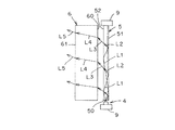
前記発光部材6は、光を透過させる性質を有する部材、この例では、アクリル、PC(ポリカーボネート)、PMMA(ポリメタクリル酸メチル、メタクリル樹脂)などの透明樹脂材からなる。前記発光部材6は、図1〜図4に示すように、板形状をなす。前記発光部材6は、入射面60と、出射面61と、意匠面62と、を有する。
(Description of the light emitting member 6)
The
前記入射面60は、前記導光部材5の前記出射面52と対向していて、前記導光部材5の前記出射面52から出射した出射光L3を前記発光部材6中に入射させる。前記入射面60は、長方形形状をなす。すなわち、前記入射面60の高さは、前記導光部材5の直径と同等もしくはほぼ同等である。前記入射面60の幅は、前記導光部材5の前記両端面の間の距離と同等もしくはほぼ同等である。
The
前記出射面61は、前記入射面60と対向して設けられていて、前記入射面60から前記発光部材6中に入射した入射光L4を外部に出射させる。前記出射面61は、前記入射面60と同等もしくはほぼ同等の長方形形状をなす。この結果、前記入射面60から前記発光部材6中に入射した前記入射光L4の大部分を前記出射面61から外部に出射させることができる。前記出射面61には、プリズムなどの配光制御素子群を設けても良い。
The
前記意匠面62は、前記発光部材6のうち、少なくとも前記インナーパネル7より前記ランプレンズ3側に配置されている部分であって、前記出射面61以外の面に施されている。前記意匠面62は、マイクロオプティクスやシボなどが施されてなるものである。なお、前記意匠面62は、板形状をなす前記発光部材6の前記入射面60と前記出射面61との間の幅広い上面もしくは下面に施して、幅狭い左右両側面に施さなくても良い。すなわち、前記意匠面62は、板形状をなす前記発光部材6の少なくとも上面もしくは下面に施せば良い。前記入射面60から前記発光部材6中に入射した前記入射光L4のうち、前記出射面61から外部に出射する大部分に対して、少ない残りの部分が前記意匠面62に達すると、拡散して外部に出射する。この結果、前記意匠面62は、ぼんやりと光る。
The
(実施形態1の作用の説明)
この実施形態1における車両用灯具1は、以上のごとき構成からなり、以下、その作用について説明する。
(Description of the operation of the first embodiment)
The
車両用灯具1の1個の光源4を点灯すると、1個の光源4から光が放射する。1個の光源4から放射した光は、図4に示すように、導光部材5の入射面50から導光部材5中に入射する。この導光部材5中に入射した入射光L1は、導光部材5中において全反射を繰り返して、入射面50と反対側の端面に導かれる。この入射光L1は、導光部材5中を導かれる際に、反射面51で均一に反射する。
When one
反射面51で反射した反射光L2は、導光部材5の出射面52から外部に均一に出射する。導光部材5から出射した出射光L3は、発光部材6の入射面60から発光部材6中に均一に入射する。発光部材6中に入射した入射光L4は、発光部材6の出射面61から外部に均一に出射する。発光部材6の出射面61から均一に出射する出射光L5により、発光部材6の出射面61が発光面として面状に均一に発光する。
The reflected light L <b> 2 reflected by the
この結果、車両用灯具1は、たとえば、テールランプ、クリアランスランプ、ポジションランプ、ターンシグナルランプ、ストップランプ、テール・ストップランプ、室内灯などとして機能する。
As a result, the
光源4の点灯時においては、インナーパネル7からランプレンズ3側に突出する発光部材6の意匠面62がぼんやりと光る。この結果、図1に示すように、車両用灯具1の斜め上のアイポイントEPからランプレンズ3を透過して灯室8内を見ると、発光部材6の出射面61が宙に浮いた状態で均一に発光して見える。
When the
(実施形態1の効果の説明)
この実施形態1における車両用灯具1は、以上のごとき構成および作用からなり、以下、その効果について説明する。
(Description of the effect of Embodiment 1)
The
この実施形態1における車両用灯具1は、発光部材6の入射面60から入射した入射光L4を、反射などさせずにそのまま、発光部材6の出射面61から外部に出射光L5として出射させるものである。このために、板状導光体中に入射した光を内面反射ステップで前面に反射させる従来の車両用灯具のように、発光部材6の出射面61において暗部の線が見えるようなことがない。これにより、見栄えを向上させることができる。
The
この実施形態1における車両用灯具1は、板形状をなす発光部材6の入射面60の高さが円柱形状をなす導光部材5の直径と同等もしくはほぼ同等であり、板形状をなす発光部材6の入射面60の幅が円柱形状をなす導光部材5の両端面の間の距離と同等もしくはほぼ同等である。このために、導光部材5の出射面52から出射する出射光L3が、発光部材6の入射面60において発光部材6中に入射光L4として入射する際に、光の損失を極力抑制することができ、光を十分に有効利用することができる。
In the
この実施形態1における車両用灯具1は、導光部材5の反射面51が導光部材5中に入射した入射光L1を反射光L2として導光部材5の出射面52側に均一に反射させる構造の反射面である。このために、均一に反射した反射光L2が導光部材5の出射面52から出射光L3として均一に出射し、その出射光L3が発光部材6の入射面60から発光部材6中に入射光L4として均一に入射し、その入射光L4が発光部材6の出射面61から出射光L5として外部に均一に出射する。これにより、発光部材6の出射面61が発光面として面状に均一に発光することができる。
In the
この実施形態1における車両用灯具1は、発光部材6の出射面61がインナーパネル7よりランプレンズ3側にランプレンズ3と対向して配置されている。このために、車両用灯具1の斜め上のアイポイントEPからランプレンズ3を透過して灯室8内を見ると、発光部材6の出射面61が宙に浮いた状態で発光して見える。
In the
この実施形態1における車両用灯具1は、発光部材6のうち少なくともインナーパネル7よりランプレンズ3側に配置されている部分であって発光部材6の出射面61以外の面には意匠面62が施されている。このために、光源4の点灯時においては、インナーパネル7からランプレンズ3側に突出する発光部材6の意匠面62がぼんやりと光る。一方、発光部材6の出射面61は、強い光で面状に発光している。この結果、図1に示すように、車両用灯具1の斜め上のアイポイントEPからランプレンズ3を透過して灯室8内を見ると、発光部材6の出射面61が宙に浮いた状態で発光して見える様子がさらに確実となる。
The
(実施形態2の構成作用効果の説明)
図6は、この発明にかかる車両用灯具の実施形態2を示す。以下、この実施形態2における車両用灯具について説明する。図中、図1〜図5と同符号は、同一のものを示す。
(Description of the configuration and effect of the second embodiment)
FIG. 6 shows
前記の実施形態1の車両用灯具1の反射面51は、プリズムの頂点(もしくは谷点)を導光部材5の一方の端面の入射面50から他方の端面に行くに従って高くなる(もしくは低くなる)ように、構成されているものである。これに対して、この実施形態2の車両用灯具の導光部材500の反射面510は、プリズムの山部(もしくは谷部)に設ける平面を導光部材5の一方の端面の入射面50から他方の端面に行くに従って高くなる(もしくは低くなる)ように、構成されているものである。
The
これにより、この実施形態2の車両用灯具の導光部材500の反射面510は、前記の実施形態1の車両用灯具1の反射面51と同様に、導光部材500の入射面から入射した入射光L1が入射面寄り側の反射面510で反射される量を少なくして、多くの量の入射光L1を入射面と反対側に導くことができる。
Thereby, the
この結果、この実施形態2の車両用灯具の導光部材500の反射面510は、導光部材500中に入射した入射光L1を反射面510により出射面52側に均一に反射させることができる。
As a result, the
(実施形態3の構成作用効果の説明)
図7は、この発明にかかる車両用灯具の実施形態3を示す。以下、この実施形態3における車両用灯具について説明する。図中、図1〜図6と同符号は、同一のものを示す。
(Description of the configuration and effect of the third embodiment)
FIG. 7 shows Embodiment 3 of the vehicular lamp according to the present invention. Hereinafter, the vehicular lamp in the third embodiment will be described. In the figure, the same reference numerals as those in FIGS. 1 to 6 denote the same components.
前記の実施形態1の車両用灯具1の発光部材6は、入射面60と出射面61とが同等もしくはほぼ同等の長方形形状をなすものである。これに対して、この実施形態3の車両用灯具の発光部材600は、出射面610の高さが入射面60の高さよりも高い。
In the
これにより、この実施形態3の車両用灯具の発光部材600の出射面610は、入射面60よりも広い面積で面状に発光することができる。特に、入射面50から入射した入射光L1を反射面51、510により出射面52側に、主光軸Zに沿ってかつ主光軸Zに対して約20°広げて反射させる導光部材5、500を使用する場合。この場合においては、主光軸Zに対して広がって反射した反射光L2が導光部材5、500の出射面52から出射光L3として主光軸Zに対して広がって均一に出射し、その出射光L3が発光部材600の入射面60から発光部材600中に入射光L4として主光軸Zに対して広がって均一に入射し、その入射光L4が発光部材600の出射面610から出射光L5として外部に主光軸Zに対して広がって均一に出射する。これにより、発光部材600の出射面610が入射面60よりも広い面積で面状に均一に発光することができる。
Thereby, the
(実施形態4の構成作用効果の説明)
図8は、この発明にかかる車両用灯具の実施形態4を示す。以下、この実施形態4における車両用灯具について説明する。図中、図1〜図7と同符号は、同一のものを示す。
(Explanation of Configuration and Effect of Embodiment 4)
FIG. 8 shows
前記の実施形態1の車両用灯具1は、直線形状の円柱形状の導光部材5と、導光部材5の直線形状に合わせた板形状の発光部材6と、を使用するものである。これに対して、この実施形態4の車両用灯具は、曲線形状の円柱形状の導光部材501と、導光部材501の曲線形状に合わせた板形状の発光部材601と、を使用するものである。これにより、発光部材601の出射面62が曲線形状の帯形状に面発光することができる。
The
(実施形態以外の例の説明)
なお、前記の実施形態においては、光源4として半導体型光源を使用するものである。ところが、この発明においては、その他の光源、たとえば、白熱光源、ハロゲン光源、放電光源を使用しても良い。
(Description of example other than embodiment)
In the above embodiment, a semiconductor light source is used as the
また、前記の実施形態においては、導光部材5、500、501の入射面50に対して1個の光源4を配置するものである。ところが、この発明においては、入射面に対して複数個の光源を配置しても良い。
Moreover, in the said embodiment, the one
1 車両用灯具
2 ランプハウジング
3 ランプレンズ
4 光源
5、500、501 導光部材
50 入射面
51、510 反射面
52 出射面
6、600、601 発光部材
60 入射面
61、610 出射面
62 意匠面
7 インナーパネル
8 灯室
9 取付ブラケット
EP アイポイント
L1 入射光
L2 反射光
L3 出射光
L4 入射光
L5 出射光
Z 主光軸
DESCRIPTION OF
Claims (4)
前記灯室内に配置されている光源および導光部材および発光部材と、
を備え、
前記導光部材は、円柱形状をなし、
該導光部材の両端面の一方の端面に設けられて、前記光源からの光を前記導光部材中に入射させる入射面と、
前記導光部材の側面のうちの一部であって、前記導光部材の前記両端面の間に設けられて、前記入射面から前記導光部材中に入射した入射光を反射させる反射面と、
前記導光部材の側面のうちの一部であって、前記導光部材の前記両端面の間に、前記反射面と対向して設けられて、前記反射面により反射された反射光を外部に出射させる出射面と、
を有し、
前記発光部材は、板形状をなし、
前記導光部材の前記出射面と対向していて、前記導光部材の前記出射面から出射した出射光を前記発光部材中に入射させる入射面と、
前記発光部材の前記入射面と対向して設けられていて、前記入射面から前記発光部材中に入射した入射光を外部に出射させる出射面と、
を有し、
前記反射面は、前記導光部材の軸方向に並ぶ多数の反射面と、該反射面と反射面との間に設けられる多数の傾斜面とを有する多数のプリズムから構成され、前記導光部材の一方の端面の前記入射面から他方の端面に向かうに従って、前記プリズムの山部に設ける平面が高くなる、もしくは、前記プリズムの谷部に設ける平面が低くなる構造を有し、前記導光部材中に入射した入射光を前記導光部材の前記出射面側に均一もしくはほぼ均一に反射させる反射面である、
ことを特徴とする車両用灯具。 A lamp housing and a lamp lens that partition the lamp chamber;
A light source, a light guide member, and a light emitting member disposed in the lamp chamber;
With
The light guide member has a cylindrical shape,
Provided on one end face of both end faces of the light guide member, an incident surface for allowing light from the light source to enter the light guide member;
A reflective surface that is a part of the side surface of the light guide member and is provided between the both end surfaces of the light guide member and reflects incident light incident on the light guide member from the incident surface; ,
A part of the side surface of the light guide member, provided between the both end faces of the light guide member so as to face the reflection surface, and reflects light reflected by the reflection surface to the outside An exit surface to emit,
Have
The light emitting member has a plate shape,
An incident surface that is opposed to the emission surface of the light guide member and causes the emitted light emitted from the emission surface of the light guide member to enter the light emitting member;
An emission surface that is provided opposite to the incident surface of the light emitting member, and that emits incident light incident on the light emitting member from the incident surface to the outside;
Have
The reflection surface is composed of a large number of prisms having a large number of reflection surfaces arranged in the axial direction of the light guide member and a large number of inclined surfaces provided between the reflection surface and the reflection surface. The light guide member has a structure in which a flat surface provided at a peak portion of the prism is increased or a flat surface provided at a trough portion of the prism is lowered as it goes from the incident surface to the other end surface of one end surface of the light guide member. It is a reflecting surface that reflects incident light incident therein uniformly or almost uniformly on the exit surface side of the light guide member,
A vehicular lamp characterized by the above.
板形状をなす前記発光部材の前記入射面の幅は、円柱形状をなす前記導光部材の前記両端面の間の距離と同等もしくはほぼ同等である、
ことを特徴とする請求項1に記載の車両用灯具。 The height of the incident surface of the light emitting member having a plate shape is equal to or substantially equal to the diameter of the light guide member having a cylindrical shape,
The width of the incident surface of the light emitting member having a plate shape is equal to or substantially equal to the distance between the both end surfaces of the light guide member having a cylindrical shape.
The vehicular lamp according to claim 1 .
前記インナーパネルには、前記発光部材が挿通されていて、
前記光源および前記導光部材および前記発光部材の前記入射面は、前記インナーパネルより前記ランプハウジング側に配置されていて、
前記発光部材の前記出射面は、前記インナーパネルより前記ランプレンズ側に前記ランプレンズと対向して配置されている、
ことを特徴とする請求項1または2に記載の車両用灯具。 In the lamp chamber, an inner panel is disposed to face the lamp lens,
The inner panel is inserted with the light emitting member,
The incident surfaces of the light source, the light guide member, and the light emitting member are disposed on the lamp housing side from the inner panel,
The emission surface of the light emitting member is disposed on the lamp lens side of the inner panel so as to face the lamp lens.
The vehicular lamp according to claim 1 or 2 .
ことを特徴とする請求項3に記載の車両用灯具。 Of the light emitting member, at least a portion disposed on the lamp lens side from the inner panel, and a surface other than the emission surface of the light emitting member is provided with a design surface.
The vehicular lamp according to claim 3 .
Priority Applications (1)
| Application Number | Priority Date | Filing Date | Title |
|---|---|---|---|
| JP2013115349A JP6251985B2 (en) | 2013-05-31 | 2013-05-31 | Vehicle lighting |
Applications Claiming Priority (1)
| Application Number | Priority Date | Filing Date | Title |
|---|---|---|---|
| JP2013115349A JP6251985B2 (en) | 2013-05-31 | 2013-05-31 | Vehicle lighting |
Publications (2)
| Publication Number | Publication Date |
|---|---|
| JP2014235819A JP2014235819A (en) | 2014-12-15 |
| JP6251985B2 true JP6251985B2 (en) | 2017-12-27 |
Family
ID=52138389
Family Applications (1)
| Application Number | Title | Priority Date | Filing Date |
|---|---|---|---|
| JP2013115349A Active JP6251985B2 (en) | 2013-05-31 | 2013-05-31 | Vehicle lighting |
Country Status (1)
| Country | Link |
|---|---|
| JP (1) | JP6251985B2 (en) |
Families Citing this family (17)
| Publication number | Priority date | Publication date | Assignee | Title |
|---|---|---|---|---|
| JP6530928B2 (en) | 2015-02-24 | 2019-06-12 | スタンレー電気株式会社 | Lighting device |
| JP6350363B2 (en) * | 2015-03-31 | 2018-07-04 | 株式会社豊田自動織機 | Vehicle lighting |
| AT517019B1 (en) * | 2015-04-02 | 2017-02-15 | Zkw Group Gmbh | Lighting device and motor vehicle headlights |
| JP6557543B2 (en) | 2015-08-04 | 2019-08-07 | 株式会社小糸製作所 | Vehicle lighting |
| AT517675B1 (en) * | 2015-08-27 | 2017-08-15 | Zkw Group Gmbh | Light module for vehicle headlights as well as headlight, tail light and side marker light |
| ITUB20155929A1 (en) * | 2015-11-26 | 2017-05-26 | Automotive Lighting Italia S P A A Socio Unico | LIGHTING DEVICE FOR VEHICLES |
| DE202015008368U1 (en) * | 2015-12-02 | 2017-03-03 | Automotive Lighting Reutlingen Gmbh | Luminaire module with a thick-walled look |
| JP6868974B2 (en) * | 2016-06-09 | 2021-05-12 | 株式会社小糸製作所 | Light fixtures for vehicles |
| JP6634641B2 (en) * | 2016-09-12 | 2020-01-22 | 株式会社小糸製作所 | Vehicle lighting |
| FR3058370B1 (en) * | 2016-11-07 | 2018-12-07 | Peugeot Citroen Automobiles Sa | SIGNALING LIGHT OF MOTOR VEHICLE |
| EP3660393B1 (en) * | 2018-11-30 | 2024-03-27 | Valeo Iluminacion, S.A. | Automotive lighting device |
| TWI662224B (en) * | 2018-12-26 | 2019-06-11 | 聯嘉光電股份有限公司 | Vehicle led linear lighting module |
| FR3096112B1 (en) * | 2019-05-16 | 2021-04-16 | Psa Automobiles Sa | Plan light guide and motor vehicle light comprising such a guide. |
| JP7354613B2 (en) * | 2019-06-27 | 2023-10-03 | 市光工業株式会社 | Vehicle lights |
| GB2585687B (en) * | 2019-07-11 | 2021-08-18 | Dyson Technology Ltd | Vehicle lamps |
| FR3099810A1 (en) * | 2019-08-07 | 2021-02-12 | Psa Automobiles Sa | Optical element for luminous device with several photometric functions and anti-light leak wall. |
| DE102019129339A1 (en) | 2019-10-30 | 2021-05-06 | HELLA GmbH & Co. KGaA | Lighting device for vehicles |
Family Cites Families (6)
| Publication number | Priority date | Publication date | Assignee | Title |
|---|---|---|---|---|
| JP3984023B2 (en) * | 2001-11-02 | 2007-09-26 | 株式会社小糸製作所 | Vehicle lamp |
| JP5320176B2 (en) * | 2009-06-16 | 2013-10-23 | 株式会社小糸製作所 | Vehicle lighting |
| JP2011216279A (en) * | 2010-03-31 | 2011-10-27 | Koito Mfg Co Ltd | Lamp fitting for vehicle |
| JP2012190762A (en) * | 2011-03-14 | 2012-10-04 | Koito Mfg Co Ltd | Lamp fitting for vehicle |
| FR2977926B1 (en) * | 2011-06-30 | 2014-09-12 | Valeo Vision | OPTICAL DEVICE AND SYSTEM FOR SIGNALING AND / OR LIGHTING |
| JP2013045671A (en) * | 2011-08-25 | 2013-03-04 | Stanley Electric Co Ltd | Vehicle lighting fixture |
-
2013
- 2013-05-31 JP JP2013115349A patent/JP6251985B2/en active Active
Also Published As
| Publication number | Publication date |
|---|---|
| JP2014235819A (en) | 2014-12-15 |
Similar Documents
| Publication | Publication Date | Title |
|---|---|---|
| JP6251985B2 (en) | Vehicle lighting | |
| JP6361248B2 (en) | Vehicle lighting | |
| JP6361245B2 (en) | Vehicle light guide member, vehicle lamp | |
| JP2012243734A (en) | Lamp fitting for vehicle | |
| JP2017228420A (en) | Light source unit and lighting fixture | |
| JP6511960B2 (en) | Vehicle lamp | |
| JP6179138B2 (en) | Vehicle lighting | |
| JP6354175B2 (en) | Vehicle light guide member, vehicle lamp | |
| JP6221438B2 (en) | Vehicle lighting | |
| JP2015170387A (en) | Vehicular light guide member and vehicular lighting tool | |
| JP6225506B2 (en) | Vehicle lighting | |
| JP5891137B2 (en) | Vehicle lighting | |
| JP2020004483A (en) | Vehicular lighting fixture | |
| JP6245022B2 (en) | Vehicle light guide member, vehicle lamp | |
| JP6035901B2 (en) | Vehicle lighting | |
| JP6127538B2 (en) | Vehicle lighting | |
| JP6790633B2 (en) | Vehicle optics and vehicle lamps with vehicle optics | |
| JP7419836B2 (en) | Vehicle lights | |
| JP2017183143A (en) | Vehicular lighting tool | |
| JP6838327B2 (en) | Vehicle optics and vehicle lamps with vehicle optics | |
| JP2016212949A (en) | Vehicular lamp | |
| JP2016024885A (en) | Vehicular lighting tool | |
| JP6354311B2 (en) | Vehicle lighting | |
| JP2016009542A (en) | Light guide member for vehicle and vehicle lamp fitting | |
| JP2015141787A (en) | Vehicular light guide member and vehicular lighting tool |
Legal Events
| Date | Code | Title | Description |
|---|---|---|---|
| A621 | Written request for application examination |
Free format text: JAPANESE INTERMEDIATE CODE: A621 Effective date: 20160428 |
|
| A131 | Notification of reasons for refusal |
Free format text: JAPANESE INTERMEDIATE CODE: A131 Effective date: 20170228 |
|
| A977 | Report on retrieval |
Free format text: JAPANESE INTERMEDIATE CODE: A971007 Effective date: 20170228 |
|
| A521 | Request for written amendment filed |
Free format text: JAPANESE INTERMEDIATE CODE: A523 Effective date: 20170501 |
|
| A131 | Notification of reasons for refusal |
Free format text: JAPANESE INTERMEDIATE CODE: A131 Effective date: 20170801 |
|
| A521 | Request for written amendment filed |
Free format text: JAPANESE INTERMEDIATE CODE: A523 Effective date: 20170928 |
|
| TRDD | Decision of grant or rejection written | ||
| A01 | Written decision to grant a patent or to grant a registration (utility model) |
Free format text: JAPANESE INTERMEDIATE CODE: A01 Effective date: 20171031 |
|
| A61 | First payment of annual fees (during grant procedure) |
Free format text: JAPANESE INTERMEDIATE CODE: A61 Effective date: 20171113 |
|
| R150 | Certificate of patent or registration of utility model |
Ref document number: 6251985 Country of ref document: JP Free format text: JAPANESE INTERMEDIATE CODE: R150 |
|
| R250 | Receipt of annual fees |
Free format text: JAPANESE INTERMEDIATE CODE: R250 |
|
| R250 | Receipt of annual fees |
Free format text: JAPANESE INTERMEDIATE CODE: R250 |
|
| R250 | Receipt of annual fees |
Free format text: JAPANESE INTERMEDIATE CODE: R250 |
|
| R250 | Receipt of annual fees |
Free format text: JAPANESE INTERMEDIATE CODE: R250 |