JP6248528B2 - Discharge lamp driving device, light source device, projector, and discharge lamp driving method - Google Patents
Discharge lamp driving device, light source device, projector, and discharge lamp driving method Download PDFInfo
- Publication number
- JP6248528B2 JP6248528B2 JP2013213473A JP2013213473A JP6248528B2 JP 6248528 B2 JP6248528 B2 JP 6248528B2 JP 2013213473 A JP2013213473 A JP 2013213473A JP 2013213473 A JP2013213473 A JP 2013213473A JP 6248528 B2 JP6248528 B2 JP 6248528B2
- Authority
- JP
- Japan
- Prior art keywords
- discharge lamp
- driving
- period
- power
- control unit
- Prior art date
- Legal status (The legal status is an assumption and is not a legal conclusion. Google has not performed a legal analysis and makes no representation as to the accuracy of the status listed.)
- Expired - Fee Related
Links
Images


Classifications
-
- H—ELECTRICITY
- H05—ELECTRIC TECHNIQUES NOT OTHERWISE PROVIDED FOR
- H05B—ELECTRIC HEATING; ELECTRIC LIGHT SOURCES NOT OTHERWISE PROVIDED FOR; CIRCUIT ARRANGEMENTS FOR ELECTRIC LIGHT SOURCES, IN GENERAL
- H05B41/00—Circuit arrangements or apparatus for igniting or operating discharge lamps
- H05B41/14—Circuit arrangements
- H05B41/36—Controlling
- H05B41/38—Controlling the intensity of light
- H05B41/39—Controlling the intensity of light continuously
- H05B41/392—Controlling the intensity of light continuously using semiconductor devices, e.g. thyristor
- H05B41/3921—Controlling the intensity of light continuously using semiconductor devices, e.g. thyristor with possibility of light intensity variations
- H05B41/3927—Controlling the intensity of light continuously using semiconductor devices, e.g. thyristor with possibility of light intensity variations by pulse width modulation
-
- H—ELECTRICITY
- H04—ELECTRIC COMMUNICATION TECHNIQUE
- H04N—PICTORIAL COMMUNICATION, e.g. TELEVISION
- H04N9/00—Details of colour television systems
- H04N9/12—Picture reproducers
- H04N9/31—Projection devices for colour picture display, e.g. using electronic spatial light modulators [ESLM]
- H04N9/3141—Constructional details thereof
- H04N9/315—Modulator illumination systems
- H04N9/3155—Modulator illumination systems for controlling the light source
-
- H—ELECTRICITY
- H05—ELECTRIC TECHNIQUES NOT OTHERWISE PROVIDED FOR
- H05B—ELECTRIC HEATING; ELECTRIC LIGHT SOURCES NOT OTHERWISE PROVIDED FOR; CIRCUIT ARRANGEMENTS FOR ELECTRIC LIGHT SOURCES, IN GENERAL
- H05B41/00—Circuit arrangements or apparatus for igniting or operating discharge lamps
- H05B41/14—Circuit arrangements
- H05B41/16—Circuit arrangements in which the lamp is fed by dc or by low-frequency ac, e.g. by 50 cycles/sec ac, or with network frequencies
-
- H—ELECTRICITY
- H05—ELECTRIC TECHNIQUES NOT OTHERWISE PROVIDED FOR
- H05B—ELECTRIC HEATING; ELECTRIC LIGHT SOURCES NOT OTHERWISE PROVIDED FOR; CIRCUIT ARRANGEMENTS FOR ELECTRIC LIGHT SOURCES, IN GENERAL
- H05B41/00—Circuit arrangements or apparatus for igniting or operating discharge lamps
- H05B41/14—Circuit arrangements
- H05B41/36—Controlling
- H05B41/38—Controlling the intensity of light
- H05B41/382—Controlling the intensity of light during the transitional start-up phase
-
- H—ELECTRICITY
- H04—ELECTRIC COMMUNICATION TECHNIQUE
- H04N—PICTORIAL COMMUNICATION, e.g. TELEVISION
- H04N9/00—Details of colour television systems
- H04N9/12—Picture reproducers
- H04N9/31—Projection devices for colour picture display, e.g. using electronic spatial light modulators [ESLM]
- H04N9/3102—Projection devices for colour picture display, e.g. using electronic spatial light modulators [ESLM] using two-dimensional electronic spatial light modulators
- H04N9/312—Driving therefor
-
- H—ELECTRICITY
- H04—ELECTRIC COMMUNICATION TECHNIQUE
- H04N—PICTORIAL COMMUNICATION, e.g. TELEVISION
- H04N9/00—Details of colour television systems
- H04N9/12—Picture reproducers
- H04N9/31—Projection devices for colour picture display, e.g. using electronic spatial light modulators [ESLM]
- H04N9/3141—Constructional details thereof
- H04N9/315—Modulator illumination systems
- H04N9/3167—Modulator illumination systems for polarizing the light beam
-
- H—ELECTRICITY
- H04—ELECTRIC COMMUNICATION TECHNIQUE
- H04N—PICTORIAL COMMUNICATION, e.g. TELEVISION
- H04N9/00—Details of colour television systems
- H04N9/12—Picture reproducers
- H04N9/31—Projection devices for colour picture display, e.g. using electronic spatial light modulators [ESLM]
- H04N9/3197—Projection devices for colour picture display, e.g. using electronic spatial light modulators [ESLM] using light modulating optical valves
Landscapes
- Engineering & Computer Science (AREA)
- Multimedia (AREA)
- Signal Processing (AREA)
- Circuit Arrangements For Discharge Lamps (AREA)
Description
本発明は、放電灯駆動装置、光源装置、プロジェクターおよび放電灯駆動方法に関する。 The present invention relates to a discharge lamp driving device, a light source device, a projector, and a discharge lamp driving method.
近年、プロジェクターには省エネルギー化が求められている。そのため、ランプへの駆動電力を通常よりも低下させる低電力モード、映像信号に同期して駆動電力を変化させる調光モード、外部から映像信号が入力されていないときに駆動電力を低下させる待機モードなど、各種の点灯モードを搭載したプロジェクターが提供されている。例えば低電力モードでは、ランプに供給される駆動電力が低いため、電極への負荷が小さくなり、ランプの寿命が長くなる。 In recent years, projectors are required to save energy. Therefore, a low power mode that reduces the driving power to the lamp than usual, a dimming mode that changes the driving power in synchronization with the video signal, and a standby mode that reduces the driving power when no video signal is input from the outside Projectors equipped with various lighting modes are provided. For example, in the low power mode, since the driving power supplied to the lamp is low, the load on the electrode is reduced and the life of the lamp is extended.
しかしながら、駆動電力が定格電力よりも小さい場合、電極先端の突起を充分に溶融させることができず、点灯を長時間続けると、突起が損耗、縮小する。突起の縮小は電極間距離が広がることとなり、照度の低下を引き起こす。つまり、電極先端の突起の形状を維持できない場合、低電力モードの利点を生かせず、ランプの寿命が短くなるという問題が生じる。そこで、この問題を解決するために、ランプ点灯後の所定の期間において、電極の突起の溶融を促進するリフレッシュ点灯モードでランプを駆動する放電灯点灯装置、およびプロジェクターが提案されている(下記の特許文献1参照)。 However, when the driving power is smaller than the rated power, the protrusion at the tip of the electrode cannot be sufficiently melted, and if the lighting is continued for a long time, the protrusion is worn and reduced. The reduction in the protrusions increases the distance between the electrodes, causing a decrease in illuminance. That is, if the shape of the protrusion at the tip of the electrode cannot be maintained, there is a problem that the advantage of the low power mode cannot be utilized and the lamp life is shortened. In order to solve this problem, a discharge lamp lighting device and a projector that drive a lamp in a refresh lighting mode that promotes melting of electrode protrusions in a predetermined period after the lamp is lit have been proposed (see below). Patent Document 1).
特許文献1のプロジェクターの場合、リフレッシュ点灯モードでは定格電力値を超えるランプ電力が供給される。この場合、通常点灯時に形成された突起が溶融され過ぎ、突起の形状が維持できないことが考えられる。その結果、ランプは、安定した放電を維持できず、フリッカーが発生する。また、発光管への負荷が大きく、石英ガラスの結晶化現象、いわゆる失透などの不具合が生じる虞がある。
In the case of the projector of
本発明の一つの態様は、上記の課題を解決するためになされたものであって、安定した放電を維持することができる放電灯駆動装置、光源装置、プロジェクターおよび放電灯駆動方法を提供することを目的の一つとする。 One aspect of the present invention is made to solve the above problems, and provides a discharge lamp driving device, a light source device, a projector, and a discharge lamp driving method capable of maintaining stable discharge. Is one of the purposes.
上記の目的を達成するために、本発明の一つの態様の放電灯駆動装置は、放電灯に駆動電力を供給する放電灯駆動部と、前記駆動電力の波形に従って前記放電灯駆動部を制御する制御部と、を備え、前記波形は、n個(n:2以上の自然数)の立上期間と、低電力モード点灯期間と、を有し、前記n個の立上期間は、駆動電力が低電力モード時電力以上、定格電力以下のリフレッシュ電力に向けて増加する第1番目の立上期間と、駆動電力が前記リフレッシュ電力に維持される(n−1)個の立上期間と、を含み、第x−1番目(x:2以上、n以下の自然数)の立上期間における駆動電力周波数をfx−1、第x番目の立上期間における駆動電力周波数をfxと表したときに、fx−1≧fxの関係を満たし、前記制御部は、前記放電灯の劣化の程度に応じて、複数の前記駆動電力周波数のうちの少なくとも一部の前記駆動電力周波数を調整することを特徴とする。 In order to achieve the above object, a discharge lamp driving device according to one aspect of the present invention controls a discharge lamp driving unit that supplies driving power to a discharge lamp, and the discharge lamp driving unit according to a waveform of the driving power. A control unit, and the waveform includes n (n: a natural number of 2 or more) rising periods and a low power mode lighting period, and the driving power is in the n rising periods. A first rising period that increases toward a refresh power that is equal to or higher than the power in the low power mode and lower than the rated power; and (n-1) rising periods in which the driving power is maintained at the refresh power. In addition, when the drive power frequency in the x−1th (x: natural number of 2 or more and n or less) rise period is expressed as fx −1 and the drive power frequency in the xth start period is expressed as fx. to satisfy the relationship f x-1 ≧ f x, the control unit, the discharge Depending on the degree of deterioration, and adjusting at least part of the driving power frequency of the plurality of the driving power frequency.
本発明の一つの態様の放電灯駆動装置は、放電灯の定格電力よりも低い低電力モード時電力で放電灯を駆動する低電力モードを有している。低電力モードで駆動したときの放電灯の電極先端の突起は、放電灯の定格電力で駆動したときの突起と比べて細くなっている。したがって、放電灯の点灯直後にいきなり溶融力が高い駆動を行うと、突起の形状が崩れる虞がある。これに対し、本発明の一つの態様の放電灯駆動装置では、駆動電力が低電力モード時電力以上、定格電力以下のリフレッシュ電力に向けて増加する第1番目の立上期間の後の立上期間では、駆動電力周波数が維持されるか、もしくは駆動電力周波数が徐々に低下する。この場合、立上期間の経過に伴って突起の溶融効果が徐々に高まるため、突起の形状を維持しつつ、突起を適度に溶融させることができる。 The discharge lamp driving device according to one aspect of the present invention has a low power mode in which the discharge lamp is driven with power in the low power mode lower than the rated power of the discharge lamp. The protrusion at the electrode tip of the discharge lamp when driven in the low power mode is thinner than the protrusion when driven at the rated power of the discharge lamp. Therefore, if the driving with a high melting power is performed immediately after the discharge lamp is turned on, the shape of the protrusion may be collapsed. On the other hand, in the discharge lamp driving device according to one aspect of the present invention, the start-up after the first start-up period in which the drive power increases toward the refresh power not lower than the power in the low power mode and lower than the rated power. In the period, the driving power frequency is maintained or the driving power frequency gradually decreases. In this case, since the melting effect of the protrusion gradually increases with the elapse of the rising period, the protrusion can be appropriately melted while maintaining the shape of the protrusion.
また、本発明の一つの態様の放電灯駆動装置は、放電灯の劣化の程度に応じて、複数の立上期間に対応する複数の駆動電力周波数のうちの少なくとも一部の駆動電力周波数を調整するため、放電灯の劣化の程度が変化しても、その劣化の程度に応じて電極先端の突起の溶融状態を常に安定して制御できる。その結果、放電が安定し、放電灯の照度変化が抑えられるとともに、放電灯の寿命を長く維持することができる。 The discharge lamp driving device according to one aspect of the present invention adjusts at least some of the driving power frequencies corresponding to the plurality of start-up periods according to the degree of deterioration of the discharge lamp. Therefore, even if the degree of deterioration of the discharge lamp changes, the molten state of the protrusion at the tip of the electrode can always be stably controlled according to the degree of deterioration. As a result, the discharge is stable, the change in illuminance of the discharge lamp is suppressed, and the life of the discharge lamp can be maintained long.
本発明の一つの態様の放電灯駆動装置において、前記立上期間における前記駆動電力の波形は、個々の立上期間における駆動電力の基本波形パターンである第1波形パターンに比べて前記放電灯への負荷が相対的に強い第2波形パターンが間欠的に挿入されていてもよい。
この構成によれば、基本波形パターンである第1波形パターン中に、放電灯への負荷が相対的に強い第2波形パターンが間欠的に挿入されることにより、突起の溶融効果を効果的に高めることができる。
In the discharge lamp driving device according to one aspect of the present invention, the waveform of the driving power in the rising period is more to the discharge lamp than the first waveform pattern that is a basic waveform pattern of the driving power in each rising period. The second waveform pattern having a relatively strong load may be inserted intermittently.
According to this configuration, the second waveform pattern having a relatively strong load on the discharge lamp is intermittently inserted into the first waveform pattern, which is the basic waveform pattern, so that the melting effect of the protrusion is effectively reduced. Can be increased.
本発明の一つの態様の放電灯駆動装置において、前記制御部は、前記第2波形パターンの挿入時間、前記第2波形パターンの挿入間隔、前記第2波形パターンの挿入回数、および前記第2波形パターンの構成のうちの少なくとも一つを、前記放電灯の劣化の程度に応じて調整してもよい。
第2波形パターンは突起の溶融効果の向上に寄与するものの、第2波形パターンを過度に入れると、突起が溶融し過ぎ、突起の形状が維持できなくなる。その点、上記の構成によれば、第2波形パターンの挿入時間、挿入間隔、挿入回数、構成等が放電灯の劣化の程度に応じて調整されるため、突起が溶融し過ぎることがなく、突起の形状が良好に維持できる。
In the discharge lamp driving device according to one aspect of the present invention, the control unit includes the insertion time of the second waveform pattern, the insertion interval of the second waveform pattern, the number of insertions of the second waveform pattern, and the second waveform. At least one of the pattern configurations may be adjusted according to the degree of deterioration of the discharge lamp.
Although the second corrugated pattern contributes to the improvement of the melting effect of the protrusions, if the second corrugated pattern is excessively inserted, the protrusions are excessively melted and the shape of the protrusions cannot be maintained. In that respect, according to the above configuration, the insertion time, the insertion interval, the number of insertions, the configuration, etc. of the second waveform pattern are adjusted according to the degree of deterioration of the discharge lamp, so that the projections do not melt too much, The shape of the protrusion can be maintained well.
本発明の一つの態様の放電灯駆動装置において、前記第2波形パターンは、前記駆動電力周波数が500Hz以下の交流駆動波形パターン、もしくは直流駆動と交流駆動とを組み合わせた駆動波形パターンを含んでいてもよい。
このように、比較的低い周波数の交流駆動、もしくは直流成分を含む駆動を採用することにより、高い溶融効果を実現することができる。
In the discharge lamp driving device according to one aspect of the present invention, the second waveform pattern includes an AC driving waveform pattern in which the driving power frequency is 500 Hz or less, or a driving waveform pattern in which DC driving and AC driving are combined. Also good.
In this way, a high melting effect can be realized by adopting a relatively low frequency AC drive or a drive including a DC component.
本発明の一つの態様の放電灯駆動装置において、前記制御部は、低電力モード時の前記放電灯の電極間電圧を参照することにより前記放電灯の劣化の程度を検出する構成であってもよい。
放電灯の電極先端の突起が損耗、縮小すると、電極間距離が大きくなり、それに伴って電極間電圧が大きくなる。したがって、放電灯の電極間電圧を参照することにより、放電灯の劣化の程度が直接的に把握でき、最適な駆動電力周波数を設定することができる。
In the discharge lamp driving device according to one aspect of the present invention, the controller may be configured to detect the degree of deterioration of the discharge lamp by referring to the voltage between the electrodes of the discharge lamp in the low power mode. Good.
When the protrusion at the tip of the electrode of the discharge lamp is worn or reduced, the distance between the electrodes increases, and the voltage between the electrodes increases accordingly. Therefore, by referring to the voltage between the electrodes of the discharge lamp, the degree of deterioration of the discharge lamp can be directly grasped, and an optimum driving power frequency can be set.
本発明の一つの態様の放電灯駆動装置において、前記制御部は、前記第1番目の立上期間内の任意の時点における電極間電圧を参照し、前記電極間電圧の参照結果から低電力モード時の電極間電圧を推定する構成であってもよい。
この構成によれば、1回の点灯毎に第1立上期間での電極間電圧を参照するため、低電力モード時の電極間電圧を精度良く推定でき、放電灯の劣化の程度を的確に検出することができる。
In the discharge lamp driving device according to one aspect of the present invention, the control unit refers to the interelectrode voltage at an arbitrary time point in the first rising period, and the low power mode is determined from the reference result of the interelectrode voltage. The structure which estimates the voltage between electrodes at the time may be sufficient.
According to this configuration, the interelectrode voltage in the first rising period is referenced every time when the lamp is turned on, so that the interelectrode voltage in the low power mode can be accurately estimated, and the degree of deterioration of the discharge lamp can be accurately determined. Can be detected.
もしくは、本発明の一つの態様の放電灯駆動装置において、前記制御部は、前回の放電灯点灯時に参照して記憶しておいた電極間電圧を次回の放電灯点灯時に読み出し、前記電極間電圧の読み出し結果から低電力モード時の電極間電圧を推定する構成であってもよい。
この構成によれば、前回の点灯時に記憶済みの電極間電圧を次回の点灯時に参照するため、低電力モード時の電極間電圧を容易に推定でき、放電灯の劣化の程度を的確に検出することができる。
Alternatively, in the discharge lamp driving device according to one aspect of the present invention, the control unit reads the inter-electrode voltage stored by referring to the previous discharge lamp lighting, and the inter-electrode voltage The configuration may be such that the voltage between the electrodes in the low power mode is estimated from the read result.
According to this configuration, the inter-electrode voltage stored at the previous lighting is referred to at the next lighting, so that the inter-electrode voltage in the low power mode can be easily estimated and the degree of deterioration of the discharge lamp can be accurately detected. be able to.
本発明の一つの態様の放電灯駆動装置において、前記第1番目の立上期間における前記駆動電力周波数は500Hz以上の交流駆動電力であってもよい。
この構成によれば、電極の突起を過度に溶融させることがなく、電極物質の無駄な蒸散を防ぐことができる。
In the discharge lamp driving device according to one aspect of the present invention, the driving power frequency in the first rising period may be AC driving power of 500 Hz or more.
According to this structure, the protrusion of the electrode is not excessively melted, and unnecessary evaporation of the electrode material can be prevented.
本発明の一つの態様の光源装置は、光を射出する放電灯と、本発明の一つの態様の放電灯駆動装置と、を備えることを特徴とする。
本発明の一つの態様によれば、安定した照度が得られ、放電灯の寿命が長い光源装置を実現することができる。
A light source device according to one aspect of the present invention includes a discharge lamp that emits light and the discharge lamp driving device according to one aspect of the present invention.
According to one aspect of the present invention, it is possible to achieve a light source device that provides stable illuminance and has a long discharge lamp life.
本発明の一つの態様のプロジェクターは、本発明の一つの態様の光源装置と、前記光源装置から射出される光を映像信号に応じて変調する光変調素子と、前記光変調素子により変調された光を被投射面上に投射する投射光学系と、を備えることを特徴とする。
本発明の一つの態様によれば、表示品位に優れ、信頼性の高いプロジェクターを実現することができる。
A projector according to one aspect of the present invention includes a light source device according to one aspect of the present invention, a light modulation element that modulates light emitted from the light source apparatus in accordance with a video signal, and the light modulation element that modulates the light. A projection optical system that projects light onto the projection surface.
According to one aspect of the present invention, a projector having excellent display quality and high reliability can be realized.
本発明の一つの態様の放電灯駆動方法は、放電灯の駆動電力波形が、n個(n:2以上の自然数)の立上期間と、低電力モード点灯期間と、を有し、前記n個の立上期間は、駆動電力が低電力モード時電力以上、定格電力以下のリフレッシュ電力に向けて増加する第1番目の立上期間と、駆動電力が前記リフレッシュ電力に維持される(n−1)個の立上期間と、を含み、第x−1番目(x:2以上、n以下の自然数)の立上期間における駆動電力周波数をfx−1、第x番目の立上期間における駆動電力周波数をfxと表したときに、fx−1≧fxの関係を満たし、前記放電灯の劣化の程度に応じて複数の前記駆動電力周波数のうちの少なくとも一部の前記駆動電力周波数を調整することを特徴とする。
本発明の一つの態様の放電灯駆動方法によれば、安定した放電が得られることで放電灯の照度変化が抑えられ、放電灯の寿命を長く維持することができる。
In the discharge lamp driving method according to one aspect of the present invention, a driving power waveform of the discharge lamp has n (n: a natural number of 2 or more) rising periods and a low power mode lighting period, and the n In each of the rising periods, the driving power is maintained at the refresh power (n−), and the first rising period in which the driving power increases toward the refresh power that is equal to or higher than the power in the low power mode and lower than the rated power. 1) the number of rising periods, and the driving power frequency in the x−1th rising period (x: a natural number of 2 or more and n or less) is fx −1 , and in the xth rising period when the driving power frequency represented as f x, satisfies the relationship of f x-1 ≧ f x, at least a portion of the driving power of the plurality of the driving power frequency, depending on the degree of deterioration of the discharge lamp The frequency is adjusted.
According to the discharge lamp driving method of one aspect of the present invention, a stable discharge can be obtained, whereby a change in illuminance of the discharge lamp can be suppressed, and the life of the discharge lamp can be maintained long.
以下、図面を参照しながら、本発明の実施形態に係るプロジェクターについて説明する。
なお、本発明の範囲は、以下の実施の形態に限定されるものではなく、本発明の技術的思想の範囲内で任意に変更可能である。また、以下の図面においては、各構成をわかりやすくするために、実際の構造と各構造における縮尺や数等を異ならせる場合がある。
Hereinafter, a projector according to an embodiment of the invention will be described with reference to the drawings.
The scope of the present invention is not limited to the following embodiment, and can be arbitrarily changed within the scope of the technical idea of the present invention. Moreover, in the following drawings, in order to make each structure easy to understand, the actual structure may be different from the scale, number, or the like in each structure.
図1に示すように、本実施形態のプロジェクター500は、光源装置200と、平行化レンズ305と、照明光学系310と、色分離光学系320と、3つの液晶ライトバルブ330R,330G,330B(光変調素子)と、クロスダイクロイックプリズム340と、投射光学系350と、を備えている。
As shown in FIG. 1, the
光源装置200から射出された光は、平行化レンズ305を通過して照明光学系310に入射する。平行化レンズ305は、光源装置200からの光を平行化する機能を有する。
Light emitted from the
照明光学系310は、光源装置200から射出される光の照度を、液晶ライトバルブ330R,330G,330B上において均一化するように調整する機能を有する。さらに、照明光学系310は、光源装置200から射出される光の偏光方向を一方向に揃える機能を有する。その理由は、光源装置200から射出される光を液晶ライトバルブ330R,330G,330Bで有効に利用するためである。
The illumination optical system 310 has a function of adjusting the illuminance of light emitted from the
照度分布と偏光方向とが調整された光は、色分離光学系320に入射する。色分離光学系320は、入射光を赤色光(R)、緑色光(G)、青色光(B)の3つの色光に分離する。3つの色光は、各色光に対応付けられた液晶ライトバルブ330R,330G,330Bによりそれぞれ変調される。液晶ライトバルブ330R,330G,330Bは、後述する液晶パネル560R,560G,560Bと、偏光板(図示せず)と、を備えている。偏光板は、液晶パネル560R,560G,560Bのそれぞれの光入射側および光射出側に配置される。
The light whose illuminance distribution and polarization direction are adjusted enters the color separation optical system 320. The color separation optical system 320 separates incident light into three color lights of red light (R), green light (G), and blue light (B). The three color lights are respectively modulated by the liquid crystal
変調された3つの色光は、クロスダイクロイックプリズム340により合成される。合成光は投射光学系350に入射する。投射光学系350は、入射光をスクリーン700(図3参照)に投射する。これにより、スクリーン700上に映像が表示される。なお、平行化レンズ305、照明光学系310、色分離光学系320、クロスダイクロイックプリズム340、投射光学系350の各々の構成としては、周知の構成を採用することができる。
The three modulated color lights are combined by the cross
図2は、光源装置200の構成を示す断面図である。光源装置200は、光源ユニット210と、放電灯点灯装置(放電灯駆動装置)10と、を備えている。図2には、光源ユニット210の断面図が示されている。光源ユニット210は、主反射鏡112と、放電灯90と、副反射鏡50と、を備えている。
FIG. 2 is a cross-sectional view showing the configuration of the
放電灯点灯装置10は、放電灯90に駆動電力(駆動電流)を供給して放電灯90を点灯させる。主反射鏡112は、放電灯90から放出された光を照射方向Dに向けて反射する。照射方向Dは、放電灯90の光軸AXと平行である。
The discharge
放電灯90の形状は、照射方向Dに沿って延びる棒状である。放電灯90の一方の端部を第1端部90e1とし、放電灯90の他方の端部を第2端部90e2とする。放電灯90の材料は、例えば、石英ガラス等の透光性材料である。放電灯90の中央部は球状に膨らんでおり、その内部は放電空間91である。放電空間91には、希ガス、金属ハロゲン化合物等を含む放電媒体であるガスが封入されている。
The shape of the
放電空間91には、第1電極92および第2電極93の先端が突出している。第1電極92は、放電空間91の第1端部90e1側に配置されている。第2電極93は、放電空間91の第2端部90e2側に配置されている。第1電極92および第2電極93の形状は、光軸AXに沿って延びる棒状である。放電空間91には、第1電極92および第2電極93の電極先端部が、所定距離だけ離れて対向するように配置されている。第1電極92および第2電極93の材料は、例えば、タングステン等の金属である。
In the
放電灯90の第1端部90e1に、第1端子536が設けられている。第1端子536と第1電極92とは、放電灯90の内部を貫通する導電性部材534により電気的に接続されている。同様に、放電灯90の第2端部90e2に、第2端子546が設けられている。第2端子546と第2電極93とは、放電灯90の内部を貫通する導電性部材544により電気的に接続されている。第1端子536および第2端子546の材料は、例えば、タングステン等の金属である。導電性部材534,544の材料としては、例えば、モリブデン箔が利用される。
A
第1端子536および第2端子546は、放電灯点灯装置10に接続されている。放電灯点灯装置10は、第1端子536および第2端子546に、放電灯90を駆動するための駆動電力を供給する。その結果、第1電極92および第2電極93の間でアーク放電が起きる。アーク放電により発生した光(放電光)は、破線の矢印で示すように、放電位置から全方向に向かって放射される。
The
主反射鏡112は、固定部材114により、放電灯90の第1端部90e1に固定されている。主反射鏡112は、放電光のうち、照射方向Dと反対側に向かって進む光を照射方向Dに向かって反射する。主反射鏡112の反射面(放電灯90側の面)の形状は、放電光を照射方向Dに向かって反射できる範囲内において、特に限定されず、例えば、回転楕円形状であっても、回転放物線形状であってもよい。例えば、主反射鏡112の反射面の形状を回転放物線形状とした場合、主反射鏡112は、放電光を光軸AXに略平行な光に変換することができる。これにより、平行化レンズ305を省略することができる。
The main reflecting
副反射鏡50は、固定部材522により、放電灯90の第2端部90e2側に固定されている。副反射鏡50の反射面(放電灯90側の面)の形状は、放電空間91の第2端部90e2側の部分を囲む球面形状である。副反射鏡50は、放電光のうち、主反射鏡112が配置された側と反対側に向かって進む光を主反射鏡112に向かって反射する。これにより、放電空間91から放射される光の利用効率を高めることができる。
The
固定部材114,522の材料は、放電灯90からの発熱に耐え得る耐熱材料である範囲内において、特に限定されず、例えば、無機接着剤である。主反射鏡112および副反射鏡50と放電灯90との配置を固定する方法としては、主反射鏡112および副反射鏡50を放電灯90に固定する方法に限らず、任意の方法を採用できる。例えば、放電灯90と主反射鏡112とを、独立にプロジェクターの筐体(図示せず)に固定してもよい。副反射鏡50についても同様である。
The material of the fixing
以下、プロジェクター500の回路構成について説明する。
図3は、本実施形態のプロジェクター500の回路構成の一例を示す図である。プロジェクター500は、図1に示した光学系の他、画像信号変換部510と、直流電源装置80と、液晶パネル560R,560G,560Bと、画像処理装置570と、CPU(Central Processing Unit)580と、を備えている。
Hereinafter, the circuit configuration of the
FIG. 3 is a diagram illustrating an example of a circuit configuration of the
画像信号変換部510は、外部から入力された画像信号502(輝度−色差信号やアナログRGB信号など)を所定のワード長のデジタルRGB信号に変換して画像信号512R,512G,512Bを生成し、画像処理装置570に供給する。
The image
画像処理装置570は、3つの画像信号512R,512G,512Bに対してそれぞれ画像処理を行う。画像処理装置570は、液晶パネル560R,560G,560Bをそれぞれ駆動するための駆動信号572R,572G,572Bを液晶パネル560R,560G,560Bに供給する。
The
直流電源装置80は、外部の交流電源600から供給される交流電圧を一定の直流電圧に変換する。直流電源装置80は、トランス(図示しないが、直流電源装置80に含まれる)の2次側にある画像信号変換部510、画像処理装置570およびトランスの1次側にある放電灯点灯装置10に直流電圧を供給する。
The DC
放電灯点灯装置10は、起動時に放電灯90の電極間に高電圧を発生し、絶縁破壊を生じさせて放電路を形成する。以後、放電灯点灯装置10は、放電灯90が放電を維持するための駆動電流Iを供給する。
The discharge
液晶パネル560R,560G,560Bは、前述した液晶ライトバルブ330R,330G,330Bにそれぞれ備えられている。液晶パネル560R,560G,560Bは、それぞれ駆動信号572R,572G,572Bに基づいて、前述した光学系を介して各液晶パネル560R,560G,560Bに入射される色光の透過率(輝度)を変調する。
CPU580は、プロジェクター500の点灯開始から消灯に至るまでの各種の動作を制御する。例えば、図3の例では、通信信号582を介して点灯命令や消灯命令を放電灯点灯装置10に出力する。CPU580は、放電灯点灯装置10から通信信号584を介して放電灯90の点灯情報を受け取る。
The
以下、放電灯点灯装置10の構成について説明する。
図4は、放電灯点灯装置10の回路構成の一例を示す図である。
放電灯点灯装置10は、図4に示すように、電力制御回路20と、極性反転回路30と、制御部40と、動作検出部60と、イグナイター回路70と、を備えている。
Hereinafter, the configuration of the discharge
FIG. 4 is a diagram illustrating an example of a circuit configuration of the discharge
As shown in FIG. 4, the discharge
電力制御回路20は、放電灯90に供給する駆動電力を生成する。本実施形態においては、電力制御回路20は、直流電源装置80からの電圧を入力とし、入力電圧を降圧して直流電流Idを出力するダウンチョッパー回路で構成されている。
The
電力制御回路20は、スイッチ素子21、ダイオード22、コイル23およびコンデンサー24を含んで構成される。スイッチ素子21は、例えば、トランジスターで構成される。本実施形態においては、スイッチ素子21の一端は直流電源装置80の正電圧側に接続され、他端はダイオード22のカソード端子およびコイル23の一端に接続されている。
The
コイル23の他端にコンデンサー24の一端が接続され、コンデンサー24の他端はダイオード22のアノード端子および直流電源装置80の負電圧側に接続されている。スイッチ素子21の制御端子には、後述する制御部40から電流制御信号が入力されてスイッチ素子21のON/OFFが制御される。電流制御信号には、例えば、PWM(Pulse Width Modulation)制御信号が用いられてもよい。
One end of a capacitor 24 is connected to the other end of the
スイッチ素子21がONすると、コイル23に電流が流れ、コイル23にエネルギーが蓄えられる。その後、スイッチ素子21がOFFすると、コイル23に蓄えられたエネルギーがコンデンサー24とダイオード22とを通る経路で放出される。その結果、スイッチ素子21がONする時間の割合に応じた直流電流Idが発生する。
When the
極性反転回路30は、電力制御回路20から入力される直流電流Idを所定のタイミングで極性反転させる。これにより、極性反転回路30は、制御された時間だけ継続する直流である駆動電流I、もしくは、任意の周波数を持つ交流である駆動電流Iを生成し、出力する。本実施形態において、極性反転回路30は、インバーターブリッジ回路(フルブリッジ回路)で構成されている。
The
極性反転回路30は、例えば、トランジスターなどで構成される第1のスイッチ素子31、第2のスイッチ素子32、第3のスイッチ素子33、および第4のスイッチ素子34を含んでいる。極性反転回路30は、直列接続された第1のスイッチ素子31および第2のスイッチ素子32と、直列接続された第3のスイッチ素子33および第4のスイッチ素子34と、が互いに並列接続された構成を有する。第1のスイッチ素子31、第2のスイッチ素子32、第3のスイッチ素子33、および第4のスイッチ素子34の制御端子には、それぞれ制御部40から極性反転制御信号が入力される。この極性反転制御信号に基づいて、第1のスイッチ素子31、第2のスイッチ素子32、第3のスイッチ素子33および第4のスイッチ素子34のON/OFF動作が制御される。
The
極性反転回路30においては、第1のスイッチ素子31および第4のスイッチ素子34と、第2のスイッチ素子32および第3のスイッチ素子33と、を交互にON/OFFさせる動作が繰り返される。これにより、電力制御回路20から出力される直流電流Idの極性が交互に反転する。第1のスイッチ素子31と第2のスイッチ素子32との共通接続点、および第3のスイッチ素子33と第4のスイッチ素子34との共通接続点から、制御された時間だけ同一極性状態を継続する直流である駆動電流I、もしくは制御された周波数をもつ交流である駆動電流Iを生成し、出力する。
In the
すなわち、極性反転回路30では、第1のスイッチ素子31および第4のスイッチ素子34がONのときには第2のスイッチ素子32および第3のスイッチ素子33がOFFであり、第1のスイッチ素子31および第4のスイッチ素子34がOFFのときには第2のスイッチ素子32および第3のスイッチ素子33がONであるように制御される。したがって、第1のスイッチ素子31および第4のスイッチ素子34がONのときには、コンデンサー24の一端から第1のスイッチ素子31、放電灯90、第4のスイッチ素子34の順に流れる駆動電流Iが発生する。第2のスイッチ素子32および第3のスイッチ素子33がONのときには、コンデンサー24の一端から第3のスイッチ素子33、放電灯90、第2のスイッチ素子32の順に流れる駆動電流Iが発生する。
That is, in the
本実施形態において、電力制御回路20と極性反転回路30とを合わせた部分が放電灯駆動部230に対応する。すなわち、放電灯駆動部230は、放電灯90を駆動する駆動電流I(駆動電力)を放電灯90に供給する。
In the present embodiment, the combined portion of the
制御部40は、放電灯駆動部230を制御する。図4の例では、制御部40は、電力制御回路20および極性反転回路30を制御することにより、駆動電流Iが同一極性を継続する保持時間、駆動電流Iの電流値(駆動電力の電力値)、周波数等のパラメーターを制御する。制御部40は、極性反転回路30に対して、駆動電流Iの極性反転タイミングにより、駆動電流Iが同一極性で継続する保持時間、駆動電流Iの周波数等を制御する極性反転制御を行う。制御部40は、電力制御回路20に対して、出力される直流電流Idの電流値を制御する電流制御を行う。
The
制御部40の構成は、特に限定されない。本実施形態においては、制御部40は、システムコントローラー41、電力制御回路コントローラー42、および極性反転回路コントローラー43を含んで構成されている。なお、制御部40は、その一部または全てを半導体集積回路で構成してもよい。
The configuration of the
システムコントローラー41は、電力制御回路コントローラー42および極性反転回路コントローラー43を制御することにより、電力制御回路20および極性反転回路30を制御する。システムコントローラー41は、動作検出部60が検出したランプ電圧Vlaおよび駆動電流Iに基づき、電力制御回路コントローラー42および極性反転回路コントローラー43を制御してもよい。
The system controller 41 controls the
本実施形態においては、システムコントローラー41は、記憶部44を含んで構成されている。記憶部44は、システムコントローラー41とは独立に設けられてもよい。
In the present embodiment, the system controller 41 includes a
システムコントローラー41は、記憶部44に格納された情報に基づき、電力制御回路20および極性反転回路30を制御してもよい。記憶部44には、例えば、駆動電流Iが同一極性で継続する保持時間、駆動電流Iの電流値、周波数、波形、変調パターン等の駆動パラメーターに関する情報が格納されていてもよい。
The system controller 41 may control the
電力制御回路コントローラー42は、システムコントローラー41からの制御信号に基づき、電力制御回路20へ電流制御信号を出力することにより、電力制御回路20を制御する。
The power
極性反転回路コントローラー43は、システムコントローラー41からの制御信号に基づき、極性反転回路30へ極性反転制御信号を出力することにより、極性反転回路30を制御する。
The polarity
制御部40は、専用回路を用いて実現され、上述した制御や後述する処理の各種制御を行うようにすることができる。これに対して、制御部40は、例えば、CPUが記憶部44に記憶された制御プログラムを実行することによりコンピューターとして機能し、これらの処理の各種制御を行うようにすることもできる。
The
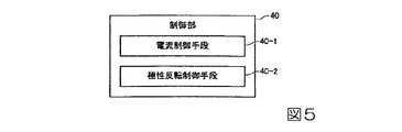
図5は、制御部40の他の構成例について説明するための図である。図5に示すように、制御部40は、制御プログラムにより、電力制御回路20を制御する電流制御手段40−1、極性反転回路30を制御する極性反転制御手段40−2として機能するように構成されてもよい。
FIG. 5 is a diagram for explaining another configuration example of the
図4に示した例では、制御部40は、放電灯点灯装置10の一部として構成されている。これに対して、制御部40の機能の一部をCPU580が担うように構成されていてもよい。
In the example shown in FIG. 4, the
動作検出部60は、例えば、放電灯90のランプ電圧を検出して制御部40にランプ電圧情報を出力する電圧検出部、駆動電流Iを検出して制御部40に駆動電流情報を出力する電流検出部、などを含んでいてもよい。本実施形態においては、動作検出部60は、第1の抵抗61、第2の抵抗62および第3の抵抗63を含んで構成されている。なお、放電灯90のランプ電圧は、放電灯90の電極間電圧を意味する。
The operation detection unit 60 detects, for example, the lamp voltage of the
本実施形態において、電圧検出部は、放電灯90と並列に、互いに直列接続された第1の抵抗61および第2の抵抗62で分圧した電圧によりランプ電圧Vlaを検出する。また、本実施形態において、電流検出部は、放電灯90に直列に接続された第3の抵抗63に発生する電圧により駆動電流Iを検出する。
In the present embodiment, the voltage detection unit detects the lamp voltage Vla by the voltage divided by the first resistor 61 and the
イグナイター回路70は、放電灯90の点灯開始時にのみ動作する。イグナイター回路70は、放電灯90の点灯開始時に放電灯90の電極間(第1電極92と第2電極93との間)を絶縁破壊して放電路を形成するために必要な高電圧(放電灯90の通常点灯時よりも高い電圧)を、放電灯90の電極間(第1電極92と第2電極93との間)に供給する。本実施形態においては、イグナイター回路70は、放電灯90と並列に接続されている。
The
図6(a),(b)には、第1電極92および第2電極93の先端部分が示されている。第1電極92および第2電極93の先端にはそれぞれ突起552p,562pが形成されている。第1電極92と第2電極93の間で生じる放電は、主として突起552pと突起562pとの間で生じる。本実施形態のように突起552p,562pがある場合には、突起が無い場合と比べて、第1電極92および第2電極93における放電位置(アーク位置)の移動を抑えることができる。
6A and 6B show the tip portions of the
図6(a)は、第1電極92が陽極として動作し、第2電極93が陰極として動作する第1極性状態を示している。第1極性状態では、放電により、第2電極93(陰極)から第1電極92(陽極)へ電子が移動する。陰極(第2電極93)からは電子が放出される。陰極(第2電極93)から放出された電子は陽極(第1電極92)の先端に衝突する。この衝突によって熱が生じ、陽極(第1電極92)の先端(突起552p)の温度が上昇する。
FIG. 6A shows a first polarity state in which the
図6(b)は、第1電極92が陰極として動作し、第2電極93が陽極として動作する第2極性状態を示している。第2極性状態では、第1極性状態とは逆に、第1電極92から第2電極93へ電子が移動する。その結果、第2電極93の先端(突起562p)の温度が上昇する。
FIG. 6B shows a second polarity state in which the
このように、電子が衝突する陽極の温度は、電子を放出する陰極の温度と比べて高くなりやすい。ここで、一方の電極の温度が他方の電極と比べて高い状態が続くことは、種々の不具合を引き起こす虞がある。例えば、高温となる電極の先端が過剰に溶けた場合には、意図しない電極の変形が生じ得る。その結果、電極間距離(アーク長)が適正値からずれ、照度が安定しない虞がある。逆に、低温となる電極の先端の溶融が不十分な場合には、先端に生じた微小な凹凸が溶けずに残る虞がある。その結果、いわゆるアークジャンプが生じる(アーク位置が安定せずに移動する)場合がある。 Thus, the temperature of the anode with which the electrons collide tends to be higher than the temperature of the cathode that emits electrons. Here, if the temperature of one electrode is higher than that of the other electrode, it may cause various problems. For example, when the tip of the electrode that becomes high temperature melts excessively, unintended electrode deformation may occur. As a result, the distance between the electrodes (arc length) may deviate from an appropriate value, and the illuminance may not be stable. On the contrary, if the tip of the electrode that is at a low temperature is not sufficiently melted, there is a possibility that minute irregularities generated at the tip may remain undissolved. As a result, a so-called arc jump may occur (the arc position moves without being stable).
本実施形態では、電極先端の突起を適度に溶融させるために、制御部40は、放電灯90に供給する駆動電力を、図7に示すように制御する。
図7は駆動電力の波形を示す図である。図7の横軸は時間(秒)であり、図7の縦軸は駆動電力(W)である。
In this embodiment, the
FIG. 7 is a diagram showing a waveform of the driving power. The horizontal axis in FIG. 7 is time (seconds), and the vertical axis in FIG. 7 is drive power (W).
放電灯90の点灯を開始すると、駆動電力は徐々に上昇した後、所定の目標電力に到達する。放電灯90の点灯直後、放電灯90の内部のプラズマ密度は小さく、温度は低く、駆動電力は不安定な状態である。その後、放電灯90の内部のプラズマ密度が大きく、温度が上昇するにつれて、駆動電力は安定な状態となる。放電灯90の点灯開始から駆動電力が安定するまでの期間を立上期間と定義する。立上期間が過ぎた後は継続的に放電灯90を点灯させる期間に入る。この期間を定常点灯期間と定義する。
When lighting of the
本実施形態の駆動電力波形においては、図7に示すように、立上期間は、第1立上期間T1、第2立上期間T2、第3立上期間T3、の3つの立上期間に分割されている。一例として、立上期間を100秒とすると、第1立上期間T1が40秒、第2立上期間T2が30秒、第3立上期間T3が30秒に設定されている。ここでは、立上期間を3つに分割したが、分割数は3に限ることはなく、n個(n:2以上の自然数)に分割してもよい。分割した各立上期間の時間も、特に限定されることなく、適宜設定が可能である。 In the driving power waveform of the present embodiment, as shown in FIG. 7, the rising period includes three rising periods of a first rising period T1, a second rising period T2, and a third rising period T3. It is divided. As an example, if the rising period is 100 seconds, the first rising period T1 is set to 40 seconds, the second rising period T2 is set to 30 seconds, and the third rising period T3 is set to 30 seconds. Here, the rising period is divided into three, but the number of divisions is not limited to three, and may be divided into n (n: a natural number of 2 or more). The time of each divided rising period is not particularly limited and can be set as appropriate.
第1立上期間T1は、駆動電力が低電力モード時電力以上、定格電力以下のリフレッシュ電力に向けて直線的に増加する期間である。これに対して、第2立上期間T2および第3立上期間T3は、駆動電力がリフレッシュ電力に維持される期間である。ただし、第2立上期間T2から第3立上期間T3にわたって、第2立上期間T2、第3立上期間T3のそれぞれの駆動電力の基本波形パターンに比べて放電灯90への負荷が相対的に強い強負荷駆動波形パターンが間欠的に挿入されている。強負荷駆動波形パターンについては、後で詳しく説明する。立上期間が終了した後、低電力モード時電力を供給する定常点灯期間(低電力モード点灯期間)が設けられている。
本実施形態の「基本波形パターン」は、特許請求の範囲の「第1波形パターン」に対応する。本実施形態の「強負荷駆動波形パターン」は、特許請求の範囲の「第2波形パターン」に対応する。
The first start-up period T1 is a period in which the drive power increases linearly toward the refresh power that is not less than the power in the low power mode and not more than the rated power. In contrast, the second rising period T2 and the third rising period T3 are periods in which the drive power is maintained at the refresh power. However, the load on the
The “basic waveform pattern” in the present embodiment corresponds to the “first waveform pattern” in the claims. The “strong load drive waveform pattern” of the present embodiment corresponds to the “second waveform pattern” in the claims.
駆動電力の具体的な一例として、放電灯90の定格電力Wtが200Wであり、リフレッシュ電力Wrが170Wであり、低電力モード時電力Wlが170Wである。すなわち、この例は、リフレッシュ電力Wrと低電力モード時電力Wlとが等しい例である。0秒〜40秒の第1立上期間T1では、駆動電力は0Vから170Wに向けて直線的に増加する。40秒〜70秒の第2立上期間T2では、駆動電力は170Wで一定に維持される。70秒〜100秒の第3立上期間T3では、駆動電力は170Wで一定に維持される。100秒以降の定常点灯期間では、駆動電力は170Wで一定に維持される。
As a specific example of the drive power, the rated power Wt of the
第1立上期間T1の駆動電力周波数をf1、第2立上期間T2の駆動電力周波数をf2、第3立上期間T3の駆動電力周波数をf3とすると、f1≧f2≧f3の関係を満たすように各駆動電力周波数が設定されている。一例として、駆動電力周波数f1が600Hz、駆動電力周波数f2が400Hz、駆動電力周波数f3が400Hzに設定されている。すなわち、第x−1番目(x:2以上、n以下の自然数)の立上期間における駆動電力周波数をfx−1、第x番目の立上期間における駆動電力周波数をfxと表したときに、fx−1≧fxの関係を満たす。定常点灯期間の駆動電力周波数は任意でよい。 Assuming that the driving power frequency in the first rising period T1 is f 1 , the driving power frequency in the second rising period T2 is f 2 , and the driving power frequency in the third rising period T3 is f 3 , f 1 ≧ f 2 ≧ each driving power frequency to satisfy the relationship of f 3 is set. As an example, the drive power frequency f 1 is set to 600 Hz, the drive power frequency f 2 is set to 400 Hz, and the drive power frequency f 3 is set to 400 Hz. That is, when the drive power frequency in the x−1th (x: natural number of 2 or more and n or less) rise time is expressed as fx −1 , and the drive power frequency in the xth start time period is expressed as fx. In addition, the relationship of f x−1 ≧ f x is satisfied. The driving power frequency in the steady lighting period may be arbitrary.
言い換えると、放電灯90の点灯直後の第1立上期間T1に対して、第2立上期間T2以降では、駆動電力周波数を維持するか、もしくは駆動電力周波数を徐々に低くする。その理由は、低電力モードで駆動した場合は定格電力で駆動した場合よりも電極先端の突起が成長せず、細くなっている。そのため、放電灯90の点灯直後にいきなり溶融効果の高い駆動を行うと、電極先端の細い突起がつぶれる虞があるからである。
In other words, with respect to the first rising period T1 immediately after the
したがって、第1立上期間T1では、500Hz以上といった比較的高い駆動電力周波数の交流駆動を行うことにより、突起の形状を維持しつつ、緩やかに突起を溶融させることができる。その後、第2立上期間T2以降では、駆動電力周波数を維持もしくは徐々に低くすることにより、突起の溶融効果を徐々に高めていき、突起を太く成長させる。その場合であっても、突起を溶融させ過ぎないような駆動電力周波数を設定することが望ましい。 Therefore, in the first rising period T1, by performing AC driving with a relatively high driving power frequency of 500 Hz or more, the protrusion can be gradually melted while maintaining the shape of the protrusion. Thereafter, in the second rise period T2 and thereafter, the driving power frequency is maintained or gradually lowered to gradually increase the melting effect of the protrusions and grow the protrusions thickly. Even in such a case, it is desirable to set the driving power frequency so as not to melt the protrusion excessively.
上記の例では、駆動電力周波数f1を600Hz、駆動電力周波数f2を400Hz、駆動電力周波数f3を400Hzとしたが、これらの駆動電力周波数は常にこの値に固定されているわけではない。図4に示す制御部40は、ランプ電圧(電極間電圧)を参照することにより放電灯90の劣化の程度を検出し、放電灯90の劣化の程度に応じて第1立上期間、第2立上期間、第3立上期間の各々の駆動電力周波数の値を適宜調整する。
In the above example, the drive power frequency f 1 is 600 Hz, the drive power frequency f 2 is 400 Hz, and the drive power frequency f 3 is 400 Hz. However, these drive power frequencies are not always fixed to this value. The
すなわち、放電灯90の劣化(損耗)が進行している程、電極間距離が増大し、電極間距離の増大に伴ってランプ電圧が高くなる。このとき、現在の立上期間から次の立上期間に移行する際の駆動電力周波数の下げ幅を大きくし、電極先端の突起をより溶融させ、突起を成長させる必要がある。したがって、プロジェクターの設計者は、参照したランプ電圧と、そのランプ電圧に対して最適な駆動電力周波数の組み合わせを予め求めておく。ランプ電圧と駆動電力周波数の組み合わせの一例を[表1]に示す。[表1]からわかるように、第3立上期間の駆動電力周波数f3は、第2立上期間の駆動電力周波数f2より低くてもよいし、第2立上期間の駆動電力周波数f2と同じでもよい。
That is, as the deterioration (wear) of the

ここで、ランプ電圧(電極間電圧)を参照してから各立上期間の駆動電力周波数を決定するまでの第1の手順について、図11を用いて説明する。
放電灯90が点灯(図11のステップS1)した後、第1立上期間T1内においてランプ電圧を参照するまでの時間(図7のtaに相当)を予め設定しておく。時間taを例えば20秒とする。制御部40は、放電灯90の点灯が開始してから時間ta(20秒)が経過したか否かを判断する(図11のステップS2)。
Here, a first procedure from referring to the lamp voltage (interelectrode voltage) to determining the driving power frequency in each rising period will be described with reference to FIG.
After the
時間ta(20秒)が経過したら、制御部40はランプ電圧を参照する(図11のステップS3)。第1立上期間T1中は駆動電力の増大に伴ってランプ電圧が徐々に上昇する。したがって、時間taで参照したランプ電圧は、定常点灯期間におけるランプ電圧とは異なる。そこで、プロジェクターの設計者は、時間taでのランプ電圧値から定常点灯期間でのランプ電圧を求める換算式、もしくは複数の放電灯を実測して得られた電圧推移の統計値に基づく換算テーブルを予め用意しておく。換算テーブルの一例を[表2]に示す。なお、[表2]では、後で説明する[表3]の強負荷駆動の挿入パターンも合わせて示している。
When the time ta (20 seconds) elapses, the
制御部40は、[表2]に基づいて、定常点灯期間におけるランプ電圧を推定し(図11のステップS4)、[表1]に基づいて、各立上期間の駆動電力周波数を決定する(図11のステップS5)。例えば、時間taで参照したランプ電圧が30Vであったとすると、[表2]から、定常点灯期間におけるランプ電圧の推定値は81〜90Vとなる。定常点灯期間におけるランプ電圧の推定値が81〜90Vであると、[表1]から、各立上期間の駆動電力周波数は、駆動電力周波数f1が600Hz、駆動電力周波数f2が400Hz、駆動電力周波数f3が400Hzとなる。
The
ところで、上述したように、第1立上期間T1では突起を緩やかに溶融させることが望ましく、第2立上期間T2以降の立上期間では、突起の溶融効果を適度に高め、突起の成長を促進することが望ましい。これを実現するために、第2立上期間T2以降の立上期間では、基本波形パターンとしての駆動電力周波数を立上期間毎に低下させる、もしくは維持することに加え、放電灯90の電極に対して基本波形パターンよりも強い負荷を与える強負荷駆動波形パターンを挿入する。
Incidentally, as described above, it is desirable that the protrusions be melted gently in the first rising period T1, and in the rising period after the second rising period T2, the melting effect of the protrusions is moderately increased, and the growth of the protrusions is increased. It is desirable to promote. In order to realize this, in the rising period after the second rising period T2, in addition to lowering or maintaining the driving power frequency as the basic waveform pattern for each rising period, the electrode of the
強負荷駆動波形パターンは、例えば、駆動電力周波数が500Hz以下の交流駆動波形パターン、もしくは直流駆動と交流駆動とを組み合わせた駆動波形パターンで構成される。本実施形態では、一例として、直流駆動と交流駆動とを含む駆動波形パターンを採用する。 The heavy load drive waveform pattern is configured by, for example, an AC drive waveform pattern with a drive power frequency of 500 Hz or less, or a drive waveform pattern in which DC drive and AC drive are combined. In the present embodiment, as an example, a driving waveform pattern including DC driving and AC driving is employed.
図10は、強負荷駆動波形パターンの一例を示す図である。
本実施形態では、図10に示すように、一方の極性の直流駆動を8ミリ秒行った後、駆動電力周波数が1.1kHzの交流波形の1周期分を5サイクル組み合わせた単位パターンを10サイクル繰り返し、その後、直流駆動の極性を反転させて同様の駆動を繰り返すパターンを採用する。この例では、同一極性の直流駆動を繰り返し10サイクル挿入することにより、一方の電極の突起の溶融を促進している。直流駆動時間は、特に限定されないが、突起の溶融効果を高めるためには直流駆動間に挟む交流駆動時間よりも長くすることが望ましい。また、双方の電極の突起を均等に溶融させるためには、強負荷駆動波形パターンの挿入期間を全体で見たときに、一方の極性の直流駆動時間と他方の極性の直流駆動時間とが等しいことが望ましい。
FIG. 10 is a diagram illustrating an example of a heavy load drive waveform pattern.
In this embodiment, as shown in FIG. 10, a unit pattern in which one cycle of an AC waveform having a driving power frequency of 1.1 kHz is combined with five cycles after DC driving of one polarity for 8 milliseconds is performed for 10 cycles. The pattern which repeats and repeats the same drive by inverting the polarity of direct current drive after that is adopted. In this example, the melting of the protrusion of one electrode is promoted by repeatedly inserting DC driving of the same polarity for 10 cycles. The DC driving time is not particularly limited, but is preferably longer than the AC driving time sandwiched between DC driving in order to enhance the melting effect of the protrusions. Also, in order to uniformly melt the protrusions of both electrodes, the DC drive time of one polarity is equal to the DC drive time of the other polarity when the insertion period of the heavy load drive waveform pattern is viewed as a whole. It is desirable.
図8は、第2立上期間T2の基本波形パターンである駆動電力周波数400Hzで、放電灯90を駆動したときの電極の温度変化を示している。
図9は、第2立上期間T2の基本波形パターン中に、図10で示した強負荷駆動波形パターンを挿入した駆動電力波形で、放電灯90を駆動したときの電極の温度変化を示している。
図8および図9において、横軸は時間[相対値]、縦軸は温度[℃]を示している。
FIG. 8 shows the temperature change of the electrodes when the
FIG. 9 is a driving power waveform obtained by inserting the heavy load driving waveform pattern shown in FIG. 10 into the basic waveform pattern of the second rising period T2, and shows the temperature change of the electrode when the
8 and 9, the horizontal axis indicates time [relative value], and the vertical axis indicates temperature [° C.].
図8、図9から明らかなように、強負荷駆動波形パターンを挿入すると、強負荷駆動波形パターンを挿入しない場合に比べて電極の温度変動幅が大きくなる。電極の温度変動幅が大きいことは、言い換えると、電極への負荷が強いことであり、突起の溶融効果が大きいことを意味する。すなわち、図9に示すような電極への負荷が強い駆動は、突起の溶融を促進し、変形、損耗した突起を再成長させる作用を有する。一方、図8に示すような基本波形パターンによる駆動は、溶融した突起の形状を安定させ、突起を緩やかに成長させる作用を有する。このように、電極への負荷が弱く、突起を緩やかに成長させる基本的な駆動に、電極への負荷が強く、突起の溶融効果が高い駆動を間欠的に挿入することにより、低電力モードでは得にくい太い突起の成長が促進される。 As is apparent from FIGS. 8 and 9, when the heavy load drive waveform pattern is inserted, the temperature fluctuation range of the electrode becomes larger than when the strong load drive waveform pattern is not inserted. In other words, the large temperature fluctuation range of the electrode means that the load on the electrode is strong and the melting effect of the protrusion is large. That is, driving with a strong load on the electrode as shown in FIG. 9 has an action of promoting melting of the protrusion and re-growing the deformed and worn protrusion. On the other hand, the driving by the basic waveform pattern as shown in FIG. 8 has an effect of stabilizing the shape of the melted protrusion and gradually growing the protrusion. In this way, in the low-power mode, by inserting a drive that has a low load on the electrode and has a strong load on the electrode and a high melting effect on the electrode into the basic drive that makes the protrusion grow slowly. The growth of thick protrusions that are difficult to obtain is promoted.
本実施形態では、制御部40は、ランプ電圧(電極間電圧)を参照することにより放電灯90の劣化の程度を検出し、放電灯90の劣化の程度に応じて強負荷駆動波形パターンの挿入の程度を適宜調整する(図11のステップS6)。具体的に、制御部40は、放電灯90の劣化の程度に応じて、強負荷駆動波形パターンの挿入時間、挿入間隔、および挿入回数の組み合わせを適宜調整する。プロジェクターの設計者は、定常点灯期間におけるランプ電圧と、そのランプ電圧に対して最適な強負荷駆動波形パターンの挿入時間、挿入間隔、および挿入回数の組み合わせを予め求めておく。ランプ電圧と強負荷駆動波形パターンの挿入時間、挿入間隔、および挿入回数の組み合わせの一例を[表3]に示す。
In the present embodiment, the
例えば、第1立上期間の時間taで参照したランプ電圧が30Vであったとすると、[表2]から、定常点灯期間におけるランプ電圧の推定値は81〜90Vとなる。定常点灯期間におけるランプ電圧の推定値が81〜90Vであると、強負荷駆動の挿入パターンはパターンDとなる。[表3]から、パターンDの場合、強負荷駆動波形パターンの挿入時間は1秒、挿入回数は5回、挿入間隔は5秒となり、図7に示すように、強負荷駆動波形パターンKを挿入することになる。 For example, assuming that the lamp voltage referenced at the time ta of the first rising period is 30V, the estimated value of the lamp voltage in the steady lighting period is 81 to 90V from [Table 2]. When the estimated value of the lamp voltage during the steady lighting period is 81 to 90 V, the insertion pattern for the heavy load drive is pattern D. From [Table 3], in the case of pattern D, the insertion time of the heavy load drive waveform pattern is 1 second, the number of insertions is 5 times, and the insertion interval is 5 seconds. As shown in FIG. Will be inserted.
なお、本実施形態では、放電灯90の劣化の程度に応じて、強負荷駆動波形パターンの挿入時間、挿入間隔、および挿入回数の3つのパラメーターを調整する例を示したが、これら3つのパラメーターに加えて、強負荷駆動波形パターンの構成そのものを調整してもよい。すなわち、図10に示した強負荷駆動波形パターン以外にも強負荷駆動波形パターンを複数種類用意しておき、放電灯90の劣化の程度に応じて複数種類の中から最適なパターンを選択するようにしてもよい。さらに、必ずしも上記4つのパラメーターを全て変化させる必要はなく、いずれかのパラメーターを固定し、残りのパラメーターのみを変化させる構成としてもよい。
In the present embodiment, an example in which three parameters of the insertion time, the insertion interval, and the number of insertions of the heavy load drive waveform pattern are adjusted according to the degree of deterioration of the
上述したように、本実施形態の放電灯点灯装置10において、放電灯90の立上期間は、第1立上期間T1から第2立上期間T2、第3立上期間T3と進むにつれて駆動電力周波数が徐々に低下しており、第2立上期間T2以降に強負荷駆動波形パターンが挿入されている。さらに、制御部40は、放電灯90の劣化の程度に応じて各立上期間の駆動電力周波数、強負荷駆動波形パターンの挿入の程度、の双方を調整する。そのため、放電灯90の劣化の程度に係わらず、電極先端の突起を常に適度に溶融させることができ、突起の形状を良好に維持することができる。その結果、放電が安定することにより、照度変化が少なく、寿命の長い光源装置200を実現できる。これにより、表示品位に優れ、信頼性の高いプロジェクター500を実現できる。
As described above, in the discharge
また、本実施形態において、制御部40は、第1立上期間T1内の任意の時間taにおけるランプ電圧を参照し、ランプ電圧の参照結果から定常点灯期間のランプ電圧を推定する構成となっている。この構成によれば、1回の点灯毎に第1立上期間T1でのランプ電圧を参照するため、定常点灯期間のランプ電圧を精度良く推定でき、放電灯90の劣化の程度を的確に検出することができる。
In the present embodiment, the
ただし、ランプ電圧の参照から駆動電力周波数および強負荷駆動波形パターンの挿入の程度の決定までの手順として、上記の第1の手順に代えて、以下の第2の手順を採用してもよい。第2の手順において、制御部40は、前回の放電灯点灯時に参照したランプ電圧を例えば記憶部44に記憶させておく。その後、次回の放電灯点灯時に、制御部40は、記憶部44からランプ電圧を読み出し、その読み出し結果から定常点灯期間のランプ電圧を推定する。
However, as a procedure from the reference of the lamp voltage to the determination of the degree of insertion of the driving power frequency and the heavy load driving waveform pattern, the following second procedure may be adopted instead of the first procedure. In the second procedure, the
第2の手順を採用した場合、前回の点灯時に記憶済みの電極間電圧を次回の点灯時に参照するため、立上期間内でランプ電圧を参照することなく、定常点灯期間のランプ電圧を容易に推定でき、放電灯90の劣化の程度を的確に検出することができる。
When the second procedure is adopted, the voltage between electrodes stored in the previous lighting is referred to in the next lighting, so that the lamp voltage in the steady lighting period can be easily obtained without referring to the lamp voltage in the rising period. The degree of deterioration of the
なお、本発明の技術範囲は上記実施形態に限定されるものではなく、本発明の趣旨を逸脱しない範囲において種々の変更を加えることが可能である。
例えば上記実施形態では、リフレッシュ電力Wrが低電力モード時電力Wlと等しい例を示した。この構成に代えて、リフレッシュ電力Wrは、低電力モード時電力Wlよりも高く、定格電力Wtよりも低い電力であってもよい。あるいは、リフレッシュ電力Wrは、定格電力Wtと等しくてもよい。すなわち、リフレッシュ電力Wrは、低電力モード時電力Wl以上、定格電力Wt以下の電力(Wl≦Wr≦Wt)であればよい。
The technical scope of the present invention is not limited to the above embodiment, and various modifications can be made without departing from the spirit of the present invention.
For example, in the above-described embodiment, an example in which the refresh power Wr is equal to the low power mode power Wl is shown. Instead of this configuration, the refresh power Wr may be higher than the low power mode power Wl and lower than the rated power Wt. Alternatively, the refresh power Wr may be equal to the rated power Wt. That is, the refresh power Wr may be a power (Wl ≦ Wr ≦ Wt) that is not less than the power Wl in the low power mode and not more than the rated power Wt.
上記実施形態では、ランプ電圧を参照することにより放電灯の劣化の程度を検出したが、この構成に代えて、例えばランプ電圧を参照することなく、放電灯の累積点灯時間を参照して放電灯の劣化の程度を検出してもよい。この場合、放電灯の累積点灯時間と駆動電力周波数との関係を示すテーブル、累積点灯時間と強負荷駆動の挿入パターンとの関係を示すテーブル等を用意しておけばよい。また、強負荷駆動波形パターンは必ずしも挿入しなくてもよい。その他、放電灯駆動装置、光源装置、プロジェクターの具体的な構成については、上記実施形態の例に限らず、適宜変更が可能である。 In the above embodiment, the degree of deterioration of the discharge lamp is detected by referring to the lamp voltage. Instead of this configuration, for example, the discharge lamp is referred to by referring to the cumulative lighting time of the discharge lamp without referring to the lamp voltage. The degree of deterioration may be detected. In this case, a table indicating the relationship between the cumulative lighting time of the discharge lamp and the drive power frequency, a table indicating the relationship between the cumulative lighting time and the insertion pattern of the heavy load drive, and the like may be prepared. Further, the heavy load drive waveform pattern may not necessarily be inserted. In addition, the specific configurations of the discharge lamp driving device, the light source device, and the projector are not limited to the above-described embodiments, and can be changed as appropriate.
10…放電灯点灯装置(放電灯駆動装置)、40…制御部、90…放電灯、230…放電灯駆動部、330R,330G,330B…液晶ライトバルブ(光変調素子)、350…投射光学系、500…プロジェクター、T1…第1立上期間、T2…第2立上期間、T3…第3立上期間。
DESCRIPTION OF
Claims (13)
前記放電灯駆動部を制御する制御部と、
を備え、
前記制御部は、前記放電灯の点灯開始から所定時間までの立上期間と、前記立上期間の後に設けられ、前記放電灯に第1駆動電力が供給される定常点灯期間と、が設けられるように前記放電灯駆動部を制御し、
前記立上期間は、前記放電灯に供給される前記駆動電力が前記第1駆動電力よりも大きい第2駆動電力に向けて増加する第1立上期間と、前記第2駆動電力が前記放電灯に供給される第2立上期間と、を含み、
前記第2立上期間において前記放電灯に供給される駆動電流の周波数は、前記第1立上期間における前記駆動電流の周波数よりも小さいことを特徴とする放電灯駆動装置。 A discharge lamp driving section for supplying driving power to the discharge lamp;
A control unit for controlling the pre-Symbol discharge lamp driving unit,
With
The control unit includes a rising period from the start of lighting of the discharge lamp to a predetermined time, and a steady lighting period that is provided after the rising period and in which the first driving power is supplied to the discharge lamp. Control the discharge lamp driving unit ,
The startup period, the first rising period and the second driving power said discharge lamp in which the driving power supplied to the discharge lamp is increased toward the second drive power greater than the first driving power A second start-up period supplied to
The discharge lamp driving device according to claim 1, wherein the frequency of the driving current supplied to the discharge lamp in the second rising period is smaller than the frequency of the driving current in the first rising period .
前記制御部は、前記放電灯の劣化の程度に応じて、前記第1立上期間における前記周波数および前記第2立上期間における前記周波数のうち少なくともいずれかを変化させることを特徴とする放電灯駆動装置。The control unit changes at least one of the frequency in the first rising period and the frequency in the second rising period according to the degree of deterioration of the discharge lamp. Drive device.
前記制御部は、前記定常点灯期間において、前記放電灯の定格電力が前記放電灯に供給されるモードと、前記定格電力よりも小さい駆動電力が前記放電灯に供給される低電力モードと、を実行可能であり、The control unit includes a mode in which the rated power of the discharge lamp is supplied to the discharge lamp in the steady lighting period, and a low power mode in which driving power smaller than the rated power is supplied to the discharge lamp. Is feasible,
前記第1駆動電力は、前記低電力モードにおける駆動電力であることを特徴とする放電灯駆動装置。The discharge lamp driving device according to claim 1, wherein the first driving power is driving power in the low power mode.
前記制御部は、前記第2立上期間において、前記駆動電流の基本波形パターンである第1波形パターンよりも前記放電灯への負荷が強い第2波形パターンを間欠的に挿入することを特徴とする放電灯駆動装置。 The discharge lamp driving device according to any one of claims 1 to 3 ,
The control unit may Oite the second rising period, that the load to the discharge lamp than the first waveform pattern is a basic waveform pattern of the driving current is inserted a strong second waveform pattern intermittently A discharge lamp driving device characterized.
前記制御部は、前記第2波形パターンの挿入時間、前記第2波形パターンの挿入間隔、前記第2波形パターンの挿入回数、および前記第2波形パターンの構成のうちの少なくとも一つを、前記放電灯の劣化の程度に応じて変化させることを特徴とする放電灯駆動装置。 The discharge lamp driving device according to claim 4 ,
The control unit releases at least one of the insertion time of the second waveform pattern, the insertion interval of the second waveform pattern, the number of insertions of the second waveform pattern, and the configuration of the second waveform pattern. A discharge lamp driving device characterized by being changed according to the degree of deterioration of an electric lamp.
前記第2波形パターンは、周波数が500Hz以下の交流電流であるパターン、もしくは直流電流と交流電流とを組み合わせたパターンを含むことを特徴とする放電灯駆動装置。 The discharge lamp driving device according to claim 4 or 5 , wherein
The second waveform pattern, frequency discharge lamp driving apparatus which comprises a pattern that combines the pattern, or the direct current and the alternating current which is less alternating current 500 Hz.
前記制御部は、前記定常点灯期間における前記放電灯の電極間電圧を参照することにより前記放電灯の劣化の程度を検出することを特徴とする放電灯駆動装置。 It is a discharge lamp drive device as described in any one of Claims 1-6 , Comprising:
The control unit detects the degree of deterioration of the discharge lamp by referring to the voltage between the electrodes of the discharge lamp during the steady lighting period .
前記制御部は、前記第1立上期間における電極間電圧を参照し、前記電極間電圧の参照結果から前記定常点灯期間における電極間電圧を推定することを特徴とする放電灯駆動装置。 The discharge lamp driving device according to claim 7 ,
Wherein the control unit, the reference to the definitive interelectrode voltage to the first start-up period, the discharge lamp driving apparatus characterized by estimating the inter-electrode voltage in the steady lighting period from the reference result of the inter-electrode voltage.
前記制御部は、前回の放電灯点灯時に参照して記憶しておいた電極間電圧を次回の放電灯点灯時に読み出し、前記電極間電圧の読み出し結果から前記定常点灯期間における電極間電圧を推定することを特徴とする放電灯駆動装置。 The discharge lamp driving device according to claim 7 ,
The control unit reads the inter-electrode voltage stored with reference to the previous discharge lamp lighting at the next discharge lamp lighting time, and estimates the inter-electrode voltage in the steady lighting period from the reading result of the inter-electrode voltage. A discharge lamp driving device characterized by that.
前記第1立上期間における前記駆動電流の周波数は、500Hz以上であることを特徴とする放電灯駆動装置。 The discharge lamp driving device according to any one of claims 1 to 9 ,
The frequency of the drive current in the first start-up period, a discharge lamp driving apparatus, characterized in that at 500Hz or more.
請求項1から請求項10のいずれか一項に記載の放電灯駆動装置と、
を備えることを特徴とする光源装置。 A discharge lamp that emits light;
The discharge lamp driving device according to any one of claims 1 to 10 ,
A light source device comprising:
前記光源装置から射出される光を映像信号に応じて変調する光変調素子と、
前記光変調素子により変調された光を投射する投射光学系と、
を備えることを特徴とするプロジェクター。 The light source device according to claim 11 ;
A light modulation element that modulates light emitted from the light source device according to a video signal;
A projection optical system for projecting light modulated by the light modulation element;
A projector comprising:
前記放電灯の点灯開始から所定時間までの立上期間と、前記立上期間の後に設けられ、前記放電灯に第1駆動電力が供給される定常点灯期間と、を有する駆動電力を前記放電灯に供給するステップを備え、
前記立上期間は、前記放電灯に供給される前記駆動電力が前記第1駆動電力よりも大きい第2駆動電力に向けて増加する第1立上期間と、前記第2駆動電力が前記放電灯に供給される第2立上期間と、を含み、
前記第2立上期間において前記放電灯に供給される駆動電流の周波数は、前記第1立上期間における前記駆動電流の周波数よりも小さいことを特徴とする放電灯駆動方法。 A discharge lamp driving method for driving the discharge lamp by supplying driving power to the discharge lamp,
And rising period until a predetermined time after the start of lighting the discharge lamp, provided after the startup period, the release of the driving power to have a, a steady lighting period where the first driving power is supplied to the discharge lamp The step of supplying to the electric light ,
The startup period, the a first start-up period in which the driving power supplied to the discharge lamp is increased toward the second drive power greater than the first driving power, the second driving power said discharge lamp A second start-up period supplied to
The discharge lamp driving method according to claim 1, wherein the frequency of the driving current supplied to the discharge lamp in the second rising period is smaller than the frequency of the driving current in the first rising period .
Priority Applications (4)
| Application Number | Priority Date | Filing Date | Title |
|---|---|---|---|
| JP2013213473A JP6248528B2 (en) | 2013-10-11 | 2013-10-11 | Discharge lamp driving device, light source device, projector, and discharge lamp driving method |
| US14/503,853 US9532439B2 (en) | 2013-10-11 | 2014-10-01 | Discharge lamp driving device, projector, and discharge lamp driving method |
| CN201410531639.2A CN104582218B (en) | 2013-10-11 | 2014-10-10 | Discharge lamp driven apparatus, light supply apparatus, projector and electric discharge lamp driving method |
| US15/355,960 US9872370B2 (en) | 2013-10-11 | 2016-11-18 | Discharge lamp driving device, projector, and discharge lamp driving method |
Applications Claiming Priority (1)
| Application Number | Priority Date | Filing Date | Title |
|---|---|---|---|
| JP2013213473A JP6248528B2 (en) | 2013-10-11 | 2013-10-11 | Discharge lamp driving device, light source device, projector, and discharge lamp driving method |
Publications (3)
| Publication Number | Publication Date |
|---|---|
| JP2015076353A JP2015076353A (en) | 2015-04-20 |
| JP2015076353A5 JP2015076353A5 (en) | 2016-08-25 |
| JP6248528B2 true JP6248528B2 (en) | 2017-12-20 |
Family
ID=52809395
Family Applications (1)
| Application Number | Title | Priority Date | Filing Date |
|---|---|---|---|
| JP2013213473A Expired - Fee Related JP6248528B2 (en) | 2013-10-11 | 2013-10-11 | Discharge lamp driving device, light source device, projector, and discharge lamp driving method |
Country Status (3)
| Country | Link |
|---|---|
| US (2) | US9532439B2 (en) |
| JP (1) | JP6248528B2 (en) |
| CN (1) | CN104582218B (en) |
Families Citing this family (2)
| Publication number | Priority date | Publication date | Assignee | Title |
|---|---|---|---|---|
| US9699423B2 (en) * | 2015-03-04 | 2017-07-04 | Seiko Epson Corporation | Projector and control method for projector |
| US10295893B2 (en) * | 2016-03-23 | 2019-05-21 | Seiko Epson Corporation | Discharge lamp driving device, light source device, projector, and discharge lamp driving method |
Family Cites Families (26)
| Publication number | Priority date | Publication date | Assignee | Title |
|---|---|---|---|---|
| JP4070420B2 (en) * | 2001-03-23 | 2008-04-02 | フェニックス電機株式会社 | Ultra high pressure discharge lamp lighting method and lighting device |
| DE60210768T2 (en) | 2001-06-13 | 2007-05-10 | Matsushita Electric Works, Ltd., Kadoma | BALLAST FOR A HIGH PERFORMANCE DISCHARGE LAMP |
| JP4019807B2 (en) | 2001-06-13 | 2007-12-12 | 松下電工株式会社 | High pressure discharge lamp lighting device |
| US7282865B2 (en) * | 2002-01-15 | 2007-10-16 | Koninklijke Philips Electronics N.V. | Device and method for operating a discharge lamp |
| JP2003338394A (en) * | 2002-05-21 | 2003-11-28 | Matsushita Electric Ind Co Ltd | Method for lighting high-pressure discharge lamp, lighting device and high-pressure discharge lamp device |
| JP4186578B2 (en) | 2002-10-09 | 2008-11-26 | ウシオ電機株式会社 | High pressure discharge lamp lighting device |
| JP2004207018A (en) | 2002-12-25 | 2004-07-22 | Seiko Epson Corp | Light source drive circuit, projector, lighting control method of light source, and computer-readable program for executing it |
| JP4400125B2 (en) | 2003-07-30 | 2010-01-20 | ウシオ電機株式会社 | Short arc type discharge lamp lighting device |
| JP4687069B2 (en) * | 2004-10-26 | 2011-05-25 | パナソニック電工株式会社 | High pressure discharge lamp lighting device and image display device |
| JP4972992B2 (en) | 2006-05-10 | 2012-07-11 | ウシオ電機株式会社 | High pressure discharge lamp lighting device |
| JP2008060071A (en) * | 2006-07-31 | 2008-03-13 | Seiko Epson Corp | Light source, light source lighting and driving thereof method and projector |
| TW200810603A (en) * | 2006-08-04 | 2008-02-16 | Greatchip Technology Co Ltd | Light-modulating circuit of discharge lamp and its control method |
| JP4974048B2 (en) | 2006-08-10 | 2012-07-11 | 岩崎電気株式会社 | High pressure discharge lamp lighting device |
| JP2008235199A (en) * | 2007-03-23 | 2008-10-02 | Harison Toshiba Lighting Corp | Discharge lamp lighting device, and image projector |
| JP4873371B2 (en) | 2007-04-24 | 2012-02-08 | 岩崎電気株式会社 | High pressure discharge lamp lighting device, projector and lighting method of high pressure discharge lamp |
| JP5179807B2 (en) * | 2007-08-31 | 2013-04-10 | パナソニック株式会社 | High pressure discharge lamp lighting method, high pressure discharge lamp lighting device, high pressure discharge lamp device, and projection-type image display device |
| JP4470985B2 (en) | 2007-09-28 | 2010-06-02 | セイコーエプソン株式会社 | Light source device and projector |
| JP4548519B2 (en) * | 2007-10-16 | 2010-09-22 | セイコーエプソン株式会社 | Light source device |
| JP2009212069A (en) * | 2008-02-07 | 2009-09-17 | Seiko Epson Corp | Lighting method of discharge lamp, lighting control device,and projector |
| JP2010113822A (en) | 2008-11-04 | 2010-05-20 | Iwasaki Electric Co Ltd | High-pressure discharge lamp lighting device and lighting method of high-pressure discharge lamp |
| JP2010198785A (en) | 2009-02-23 | 2010-09-09 | Panasonic Electric Works Co Ltd | High pressure discharge lamp lighting device, lighting apparatus, and lighting system |
| JP5434195B2 (en) * | 2009-03-31 | 2014-03-05 | トヨタ自動車株式会社 | Fuel cell system and vehicle equipped with the same |
| JP4985690B2 (en) * | 2009-03-31 | 2012-07-25 | ウシオ電機株式会社 | High pressure discharge lamp lighting device |
| EP2399431A1 (en) * | 2009-05-15 | 2011-12-28 | Osram AG | Method for operating a projector having a high-pressure discharge lamp |
| US8060560B2 (en) * | 2009-08-27 | 2011-11-15 | Net Power And Light, Inc. | System and method for pervasive computing |
| JP5273197B2 (en) * | 2011-05-13 | 2013-08-28 | ウシオ電機株式会社 | Power supply device for high-pressure discharge lamp |
-
2013
- 2013-10-11 JP JP2013213473A patent/JP6248528B2/en not_active Expired - Fee Related
-
2014
- 2014-10-01 US US14/503,853 patent/US9532439B2/en active Active
- 2014-10-10 CN CN201410531639.2A patent/CN104582218B/en active Active
-
2016
- 2016-11-18 US US15/355,960 patent/US9872370B2/en active Active
Also Published As
| Publication number | Publication date |
|---|---|
| US9532439B2 (en) | 2016-12-27 |
| US9872370B2 (en) | 2018-01-16 |
| CN104582218A (en) | 2015-04-29 |
| US20150103322A1 (en) | 2015-04-16 |
| JP2015076353A (en) | 2015-04-20 |
| US20170071052A1 (en) | 2017-03-09 |
| CN104582218B (en) | 2017-06-06 |
Similar Documents
| Publication | Publication Date | Title |
|---|---|---|
| JP5333762B2 (en) | Discharge lamp lighting device, projector, and discharge lamp driving method | |
| JP6610304B2 (en) | Discharge lamp driving device, light source device, projector, and discharge lamp driving method | |
| JP5267117B2 (en) | Discharge lamp lighting device, projector, and control method of discharge lamp lighting device | |
| JP6503867B2 (en) | Discharge lamp driving device, light source device, projector, and discharge lamp driving method | |
| JP6303704B2 (en) | Discharge lamp driving device, light source device, projector, and discharge lamp driving method | |
| JP6365061B2 (en) | Discharge lamp driving device, light source device, projector, and discharge lamp driving method | |
| JP6248528B2 (en) | Discharge lamp driving device, light source device, projector, and discharge lamp driving method | |
| JP6477048B2 (en) | Discharge lamp driving device, light source device, projector, and discharge lamp driving method | |
| JP5645012B2 (en) | Discharge lamp lighting device, projector, and discharge lamp driving method | |
| JP6477049B2 (en) | Discharge lamp driving device, light source device, projector, and discharge lamp driving method | |
| JP2018147729A (en) | Discharge lamp drive device, light source device, projector and discharge lamp drive method | |
| JP2016162613A (en) | Discharge lamp drive device, light source device, projector, and discharge lamp drive method | |
| JP2016051628A (en) | Discharge lamp driving device, light source device, projector, and discharge lamp driving method | |
| JP6547337B2 (en) | Discharge lamp driving device, light source device, projector, and discharge lamp driving method | |
| JP6592971B2 (en) | Discharge lamp driving device, light source device, projector, and discharge lamp driving method | |
| JP2018022560A (en) | Discharge lamp drive device, light source device, projector, and discharge lamp drive method | |
| JP2018073763A (en) | Discharge lamp driving device, light source device, projector, and discharge lamp driving method | |
| JP2016162615A (en) | Discharge lamp drive device, light source device, projector, and discharge lamp drive method | |
| JP6582576B2 (en) | Discharge lamp driving device, light source device, projector, and discharge lamp driving method | |
| JP6485101B2 (en) | Discharge lamp driving device, light source device, projector, and discharge lamp driving method | |
| JP2016157562A (en) | Discharge lamp driving device, light source device, projector and discharge lamp driving method | |
| JP6575137B2 (en) | Discharge lamp driving device, light source device, projector, and discharge lamp driving method | |
| JP6592972B2 (en) | Discharge lamp driving device, light source device, projector, and discharge lamp driving method | |
| JP2015106478A (en) | Discharge lamp driving device, light source device, projector, and discharge lamp driving method | |
| JP2017188314A (en) | Discharge lamp drive device, light source device, projector, and discharge lamp drive method |
Legal Events
| Date | Code | Title | Description |
|---|---|---|---|
| RD04 | Notification of resignation of power of attorney |
Free format text: JAPANESE INTERMEDIATE CODE: A7424 Effective date: 20150114 |
|
| RD04 | Notification of resignation of power of attorney |
Free format text: JAPANESE INTERMEDIATE CODE: A7424 Effective date: 20160617 |
|
| RD03 | Notification of appointment of power of attorney |
Free format text: JAPANESE INTERMEDIATE CODE: A7423 Effective date: 20160627 |
|
| A521 | Request for written amendment filed |
Free format text: JAPANESE INTERMEDIATE CODE: A523 Effective date: 20160708 |
|
| A621 | Written request for application examination |
Free format text: JAPANESE INTERMEDIATE CODE: A621 Effective date: 20160708 |
|
| A977 | Report on retrieval |
Free format text: JAPANESE INTERMEDIATE CODE: A971007 Effective date: 20170621 |
|
| A131 | Notification of reasons for refusal |
Free format text: JAPANESE INTERMEDIATE CODE: A131 Effective date: 20170627 |
|
| TRDD | Decision of grant or rejection written | ||
| A01 | Written decision to grant a patent or to grant a registration (utility model) |
Free format text: JAPANESE INTERMEDIATE CODE: A01 Effective date: 20171024 |
|
| A61 | First payment of annual fees (during grant procedure) |
Free format text: JAPANESE INTERMEDIATE CODE: A61 Effective date: 20171106 |
|
| R150 | Certificate of patent or registration of utility model |
Ref document number: 6248528 Country of ref document: JP Free format text: JAPANESE INTERMEDIATE CODE: R150 |
|
| LAPS | Cancellation because of no payment of annual fees |