JP6247057B2 - Column base fixing structure - Google Patents
Column base fixing structure Download PDFInfo
- Publication number
- JP6247057B2 JP6247057B2 JP2013184111A JP2013184111A JP6247057B2 JP 6247057 B2 JP6247057 B2 JP 6247057B2 JP 2013184111 A JP2013184111 A JP 2013184111A JP 2013184111 A JP2013184111 A JP 2013184111A JP 6247057 B2 JP6247057 B2 JP 6247057B2
- Authority
- JP
- Japan
- Prior art keywords
- column
- foundation
- base
- fixing structure
- connecting member
- Prior art date
- Legal status (The legal status is an assumption and is not a legal conclusion. Google has not performed a legal analysis and makes no representation as to the accuracy of the status listed.)
- Active
Links
Images


Description
本発明は、木造建築物における柱を基礎に固定する柱脚部固定構造に係り、特にコンクリートの基礎上に木材からなる土台を水平方向に配置し、その上に立設した木材からなる柱の脚部を固定する構造に関するものである。 The present invention relates to a column base fixing structure for fixing a pillar in a wooden building to a foundation, and in particular, a base made of wood arranged on a concrete base in a horizontal direction on a concrete foundation, and The present invention relates to a structure for fixing a leg portion.
多くの木造建築物では、コンクリートの基礎上に、木材からなる土台が水平方向に設置され、この上に木材からなる柱が立設される。土台は、木造建築物の壁体に沿った方向に配置され、基礎に下端部が埋め込まれたアンカーによって固定される。
柱は、建築物の重量及び荷重を支持するものであるが、地震時、強風時等においては引き抜こうとする方向の力つまり上揚力が作用することがある。特に隣り合う柱間に筋交い又は構造用面材を固定した耐力壁を構成する柱では、柱に大きな上揚力が作用することがある。このため、柱にはいわゆるホールダウン部材を取り付けて、柱が引き抜かれるように上方へ変位するのを抑止する構造が採用される。
In many wooden buildings, a base made of wood is installed horizontally on a concrete foundation, and a pillar made of wood is erected on this. The foundation is arranged in a direction along the wall of the wooden building and is fixed by an anchor having a lower end embedded in the foundation.
The column supports the weight and load of the building, but in the event of an earthquake or strong wind, a force in the direction of pulling out, that is, a lifting force may act. In particular, in a column constituting a bearing wall in which a bracing or a structural face material is fixed between adjacent columns, a large lifting force may act on the column. For this reason, a structure is employed in which a so-called hole-down member is attached to the column to prevent the column from being displaced upward so that the column can be pulled out.
ホールダウン部材は、例えば特許文献1に記載されている。このホールダウン部材102は、図11に示すように、柱101の側面に取り付け金具103を固定し、コンクリートの基礎104に下端部が埋め込まれたアンカー105と上記取り付け金具103とを連結ボルト106で連結する。これにより、柱が基礎104から引き上げられるように変位するのを抑えるものとなっている。上記ホールダウン部材102が取り付けられる柱101の側面は、多くの場合に壁面と直角方向の面となっている。そして、アンカー105は基礎104の上面から突出した上部が土台107に形成された貫通孔に挿通され、土台107の上方で連結ボルト106に連結される。
The hole-down member is described in
木造建築物は、住宅等の小規模のものが多いが三階建の住宅が増加しており、やや大きい規模の建築物に適用されることも増加している。このような建築物では、柱脚部に作用する上揚力も大きくなり、特許文献1に記載されているようなホールダウン部材では耐力が不足することがある。
Although many wooden buildings are small-scale, such as houses, three-story houses are increasing, and the number of wooden buildings is also increasing to be applied to slightly larger buildings. In such a building, the lifting force acting on the column base portion also increases, and the proof strength of the hole-down member described in
一般に、柱脚部が破壊されるパターンとしては、大きな上揚力が作用したときに、ホールダウン部材を柱の側面に固定した部分で、柱が避けるように破壊され、上揚力に抵抗する力が失われることが考えられる。また、耐力壁では両側の柱の一方に大きな上揚力が作用すると他方の柱には下方への荷重が大きく作用し、土台が圧壊して過大な変形が生じることがある。 In general, as a pattern in which the column base is destroyed, when a large lifting force is applied, the hole down member is fixed to the side of the column, and the column is broken to avoid the force that resists the lifting force. It can be lost. In addition, when a large lifting force is applied to one of the columns on both sides of the bearing wall, a large downward load is applied to the other column, and the foundation is crushed and excessive deformation may occur.
大きな上揚力の作用時に、上記のようなパターンの破壊に対して大きな抵抗力を有するためには、ホールダウン部材を一つの柱に複数を取り付けることが考えられる。しかし、柱の同じ側面に複数を取り付けるためには柱を太くする必要が生じる。また、壁面と直角となる2つの側面にそれぞれホールダウン部材を取り付けることも考えられるが、地震時等の水平力が作用したときには柱が傾斜し、2つのホールダウン部材に均等に力が作用しない。このため、破壊までの耐力を充分に向上させることができない。 In order to have a large resistance against the destruction of the pattern as described above when a large lifting force is applied, a plurality of hole down members may be attached to one column. However, in order to attach a plurality to the same side of the pillar, it is necessary to thicken the pillar. It is also possible to attach a hole down member to each of two side surfaces that are perpendicular to the wall surface. However, when a horizontal force is applied during an earthquake or the like, the column is inclined and the force does not act equally on the two hole down members. . For this reason, the proof strength until destruction cannot be improved sufficiently.
本発明は、上記のような事情に鑑みてなされたものであり、その目的は、木材からなる柱に作用する大きな上揚力に抵抗し、柱から基礎に力を確実に伝達することが可能となる柱脚部固定構造を提供することである。 The present invention has been made in view of the above circumstances, and its purpose is to resist a large lifting force acting on a pillar made of wood, and to reliably transmit force from the pillar to the foundation. It is to provide a column base fixing structure.
上記課題を解決するために、請求項1に係る発明は、 木造建築物の壁面の方向に沿って形成されたコンクリートの基礎上に固定支持された木材からなる土台と、 該土台上に立設された木材からなる柱と、 該柱に作用する上揚力を前記基礎に伝達して該柱が浮き上がるのを抑えるホールダウン部材と、を有する柱脚部固定構造であって、 前記ホールダウン部材は、前記柱の前記壁面とほぼ平行となった2つの側面にそれぞれ接合された2つの柱接合部と、該柱の下端面より下方で2つの前記柱接合部を互いに連結する下端連結部と、を有し、 2つの前記柱接合部と前記下端連結部と前記柱とが前記土台を囲むように連結されており、 該下端連結部が前記基礎に固定されている柱脚部固定構造を提供する。
In order to solve the above-mentioned problems, the invention according to
この柱脚部固定構造では、柱の壁面と平行となった2つの側面のそれぞれに柱接合部が取り付けられているので、柱に作用する上揚力は2つの柱接合部に分散して伝達され、柱接合部の破壊に対する耐力が向上する。そして、柱接合部が取り付けられた側面は壁面と平行となった側面であり、壁面と平行な方向に変形が生じても2つの柱接合部に作用する力は均等に近い状態で分散され、一方が先行して破壊されるのを抑制することができる。さらに、2つの柱接合部は柱の下端面より下方で互いに連結され、この下端連結部が基礎に固定されるので、柱に作用する上揚力は2つの柱接合部に分割して伝達されるが、これらの合力は柱の壁厚方向の中心付近に作用し、この合力の作用線に沿って基礎に伝達することができる。したがって、土台及び柱を含む壁体に生じるねじれやゆがみを抑制した状態で上揚力に抵抗することが可能となる。 In this column base fixing structure, the column joint is attached to each of the two side surfaces parallel to the wall surface of the column, so that the lifting force acting on the column is distributed and transmitted to the two column junctions. Moreover, the proof strength against destruction of a column junction part improves. And the side surface to which the column joint portion is attached is a side surface that is parallel to the wall surface, and even if deformation occurs in the direction parallel to the wall surface, the force acting on the two column joint portions is dispersed in a state that is nearly equal, One can be prevented from being destroyed in advance. Further, the two column joints are connected to each other below the lower end surface of the column, and the lower end connection portion is fixed to the foundation, so that the lifting force acting on the column is divided and transmitted to the two column joints. However, these resultant forces act near the center of the column in the wall thickness direction, and can be transmitted to the foundation along the line of action of this resultant force. Therefore, it is possible to resist the lifting force in a state in which twisting and distortion occurring in the wall body including the base and the column are suppressed.
請求項2に係る発明は、請求項1に記載の柱脚部固定構造において、 前記下端連結部は、前記土台の下側に設けられた鋼からなる連結部材を有し、 前記柱接合部が該連結部材に接合され、2つの前記柱接合部と前記連結部材と前記柱とが前記土台を囲むように連結されており、 前記連結部材に結合されたアンカー部材が前記基礎に埋め込まれているものとする。
The invention according to
この柱脚部固定構造では、2つの柱接合部と連結部材とで土台を柱の下側に囲い込むように保持した状態で固定される。したがって、地震時等において大きな上揚力が作用したときにも柱と土台との相対的な変位が拘束された状態で基礎に保持される。 In this column base fixing structure, the base is fixed in a state of being held so as to surround the bottom of the column by the two column joints and the connecting member. Therefore, even when a large lifting force is applied during an earthquake or the like, the relative displacement between the column and the base is held on the foundation in a constrained state.
請求項3に係る発明は、請求項2に記載の柱脚部固定構造において、 前記柱接合部は、鋼からなる板材によって形成され、 前記連結部材は、前記基礎上で水平方向に支持された鋼からなる板状の部材であり、 前記柱の下端は、前記土台上に載置された柱支持板を介して該土台上に支持されており、 前記土台を貫通し、上端が前記柱支持板の下面に当接され、下端が前記連結部材に当接された柱支持部材を有するものとする。
The invention according to
この柱脚部固定構造では、柱接合部は板状となっており、柱の壁面と平行となる面に取り付けても壁体の厚さを大きくすることなく、内装材又は外装材の内側に納めることができる。また、板状となった連結部材と容易に接合することが容易となる。そして、土台を貫通して板状の連結部材と柱支持板との間に介挿された柱支持部材によって柱から作用する鉛直下方への力が基礎に伝達され、土台に作用する圧縮力が低減される。一般に木材は木目と平行な方向に比べて木目と直角となる方向には圧縮耐力が著しく小さくなっているが、上記構成によって土台の変形が抑制され、柱から下方への力が作用する場合においても大きな耐力を有するものとなる。 In this column base fixing structure, the column junction is plate-shaped, and it can be attached to the inside of the interior or exterior material without increasing the thickness of the wall even if it is attached to a surface parallel to the wall surface of the column. Can be paid. Moreover, it becomes easy to join easily with the connection member made into plate shape. The vertical downward force acting from the column is transmitted to the foundation by the column support member inserted between the plate-like connecting member and the column support plate through the foundation, and the compressive force acting on the foundation is Reduced. In general, the compressive yield strength of wood is significantly smaller in the direction perpendicular to the grain than in the direction parallel to the grain, but the above structure suppresses the deformation of the base and the downward force acts from the column. Has a large proof stress.
請求項4に係る発明は、 木造建築物の壁面の方向に沿って形成されたコンクリートの基礎上に固定支持された木材からなる土台と、 該土台上に立設された木材からなる柱と、 該柱に作用する上揚力を前記基礎に伝達して該柱が浮き上がるのを抑えるホールダウン部材と、を有する柱脚部固定構造であって、 前記ホールダウン部材は、前記柱の前記壁面とほぼ平行となった2つの側面にそれぞれ接合された2つの柱接合部と、該柱の下端面より下方で2つの前記柱接合部を互いに連結する下端連結部と、を有し、 該下端連結部が前記基礎に固定されており、 該下端連結部は、前記基礎上に支持された連結部材又は前記基礎の上部に埋め込まれた連結部材を有し、 前記柱接合部の下端部に形成された雄ねじ部を、前記連結部材の壁面と直角方向の両端部に設けられたねじ穴に螺合することによって該連結部材と結合されている柱脚部固定構造を提供するものである。
The invention according to
この柱脚部固定構造では、予め基礎に固定されている連結部材に対して柱接合部を容易に連結することができる。そして、基礎に固定されている連結部材と2つの柱接合部とによって土台を柱の下側に囲い込むように保持した状態で固定することができる。 In this column base portion fixing structure, the column joint portion can be easily connected to a connecting member fixed in advance to the foundation. And it can fix in the state hold | maintained so that the base might be enclosed under a pillar by the connection member and two pillar junction part which are being fixed to the foundation.
請求項5に係る発明は、 木造建築物の壁面の方向に沿って形成されたコンクリートの基礎上に固定支持された木材からなる土台と、 該土台上に立設された木材からなる柱と、 該柱に作用する上揚力を前記基礎に伝達して該柱が浮き上がるのを抑えるホールダウン部材と、を有する柱脚部固定構造であって、 前記ホールダウン部材は、前記柱の前記壁面とほぼ平行となった2つの側面にそれぞれ接合された2つの柱接合部と、該柱の下端面より下方で2つの前記柱接合部を互いに連結する下端連結部と、を有し、 該下端連結部が前記基礎に固定されており、 該下端連結部は、前記基礎の上面より下方において該基礎に埋め込まれ、前記壁面と直角方向の両端部が該基礎の鉛直面に露出した連結部材を有し、 前記柱接合部は、柱の側面及び前記基礎の鉛直面に沿って配置され、前記連結部材の前記基礎から露出した端部に結合されている柱脚部固定構造を提供するものである。
The invention according to
この柱脚部固定構造では、予め基礎に埋め込まれている連結部材に対して柱接合部を容易に連結することができる。また、簡単な構造で基礎に上揚力を伝達することが可能となる。 In this column base portion fixing structure, the column joint portion can be easily connected to a connecting member embedded in advance in the foundation. In addition, it is possible to transmit the lifting force to the foundation with a simple structure.
請求項6に係る発明は、請求項4又は請求項5に記載の柱脚部固定構造において、 前記柱の下端は、前記土台の上側に配置された柱支持板を介して支持され、 該柱支持板の下側には、前記土台を上下方向に貫通し、該柱支持板から基礎に上方からの力を伝達する柱支持部材を有するものとする。
The invention according to
この柱脚部固定構造では、土台を上下方向に貫通する柱支持部材によって柱から鉛直下方に作用する力に抵抗することができ 土台に作用する鉛直方向の力を低減して土台の変形を抑制することができる。したがって、柱から鉛直下方へ作用する力に対する耐力を増大することができる。 In this column base fixing structure, the column support member that penetrates the base in the vertical direction can resist the force acting vertically downward from the column, thereby reducing the vertical force acting on the base and suppressing the deformation of the base. can do. Therefore, it is possible to increase the proof strength against the force acting vertically downward from the column.
以上説明したように、本発明に係る柱脚部固定構造では、柱に作用する上揚力は、柱の壁面と平行となった2つの側面にそれぞれ取り付けられた柱接合部にほぼ均等に分散して伝達され、一方が先行して破壊されるのを抑制することができる。したがって、柱に作用する上揚力に対して耐力が向上する。そして、2つの柱接合部を柱の下側で連結した下端連結部を基礎に固定することによって、柱に作用する上揚力の作用線に対して偏心させることなく該上揚力を安定した状態で基礎に伝達することができる。 As described above, in the column base fixing structure according to the present invention, the lifting force acting on the column is distributed almost evenly on the column joints attached to the two side surfaces parallel to the wall surface of the column. It is possible to suppress that one is destroyed in advance. Therefore, the yield strength is improved against the lifting force acting on the column. And by fixing the lower end connecting part connecting the two column joints on the lower side of the column to the foundation, the uplift force is stable without being decentered with respect to the line of action of the uplift force acting on the column. Can communicate to the foundation.
以下、本発明の実施の形態を図に基づいて説明する。
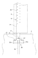
図1は、木造建築物に設けられた耐力壁の部分を示す側面図及び断面図であり、この耐力壁を構成する2つの柱に本発明の一実施形態である柱脚部固定構造が適用されている。
この耐力壁は、コンクリートの基礎1上に壁面の方向に沿って配置された土台2と、この土台の上に立設された2つのの柱3a,3bと、この柱3の上に支持された横架材4と、2つの柱3a,3b間に水平方向に架け渡された複数の胴つなぎ材5と、2つの柱3a,3bと土台2と横架材4とで囲まれた範囲の全域に壁面を形成するように取り付けられた合板6とによって主要部が構成されている。そして、上記柱3a,3bの脚部がホールダウン部材9によって基礎と連結されている。
Hereinafter, embodiments of the present invention will be described with reference to the drawings.
1A and 1B are a side view and a cross-sectional view showing a part of a load bearing wall provided in a wooden building, and a column base fixing structure according to an embodiment of the present invention is applied to two columns constituting the load bearing wall. Has been.
The load-bearing wall is supported on a
上記土台2は、コンクリートの基礎1上に水平方向に支持され、基礎1を構成するコンクリートに下端部が埋め込まれた複数のアンカーボルト7の上部が貫通している。このアンカーボルト7の上部に形成された雄ねじに螺合したナット8を締め付けることによって、土台2が基礎1に固定され、上方へ持ち上げようとする力及び水平方向に移動しようとする力に対して抵抗できるものとなっている。
なお、上記基礎1は、耐力壁の壁面に沿った向に連続するように立ち上げられた壁状部を有する布基礎となっている。
The
The
上記柱3は、土台2上に鋼の板材からなる柱支持板11を載置し、下端面を柱支持板上に当接して立設され、上端面の上に横架材4を載置して支持するものである。これらの柱3の断面は、形成する壁の面と平行な方向の寸法が壁面と直角となる方向の寸法より大きい長方形となっている。これらの柱3の下端面と上端面にはそれぞれ「ほぞ」が形成されており、下端部の「ほぞ」は、柱支持板11に設けられた開口を貫通して土台2に形成されたほぞ穴に嵌め合わされている。また、上端部に形成された「ほぞ」は、横架材4の下面に形成されたほぞ穴に嵌め入れられている。これにより、柱3と土台2との間及び柱3と横架材4との間で水平方向の相対的な変位が生じないようになっている。
The
上記横架材4は、上層階の荷重又は屋根を支持するものであり、上層階の床組、屋根を支持する小屋組や垂木等から作用する荷重を支持し、柱3に鉛直荷重を伝達することができるように断面寸法等が適宜に選択されるものである。また、この横架材4と柱3との間には、横架材4が柱3の上面から浮き上がるのを抑止するために押さえ金具12が取り付けられている。この押さえ金具12は柱3の側面に固定された取り付け金具12aと、一端がこの取り付け金具12aに係止され、上部が横架材4を上下方向に貫通してこの横架材4の上面に係止されたボルト12bと、によって主要部が構成されている。
The
上記胴つなぎ材5は、2つの柱3a,3b間にほぼ水平方向に架け渡され、両端が柱3a,3bの側面に突き当てられるともに、柱に設けられた切り欠き部に嵌め入れられて、上下方向に連結位置がずれないように固定されている。これらの胴つなぎ材5は、柱3a,3b間に取り付けられる面材つまり合板6が柱3と横架材4と土台2とで囲まれる範囲で連続するように、上下に隣り合う合板6の縁部をつなぎ合わせるために設けられたものである。耐力壁を構成する面材は柱と横架材と土台とで囲まれる範囲で連続した一枚の板材を用いるのが望ましいが、木造建築物の規模が大きくなった場合等においては柱と横架材と土台とで囲まれる範囲が大きくなることがある。このような場合には、柱と横架材と土台とで囲まれる範囲に取り付ける面材を一枚の連続した板材とすることが難しくなる。このため、胴つなぎ材5を設け、2つの柱3a,3bと胴つなぎ材5と土台2とで囲まれた矩形の範囲、2つの柱3a,3bと2つの胴つなぎ材5,5とで囲まれた範囲、及び2つの柱3a,3bと胴つなぎ材5と横架材4とで囲まれた範囲のそれぞれに一枚の連続した合板を取り付けて、2つの柱3a,3bと土台2と横架材4とで形成される枠体の変形を拘束するものとしている。
The
上記合板6は、上記のように2つの柱3a,3bと胴つなぎ材5と土台2とで囲まれた矩形の範囲、2つの柱3a,3bと2つの胴つなぎ材5,5とで囲まれた範囲、及び2つの柱3a,3bと胴つなぎ材5と横架材4とで囲まれた範囲のそれぞれに取り付けられ、合板6の4辺は、ビス、釘、螺旋状の溝が周面に形成された釘(ラグスクリュー)等を用いて強固に固定されるものである。これらの合板6は、2つの柱3a,3b、横架材4、土台2及び胴つなぎ材5とで構成される枠体の両面に取り付けられており、双方の面で枠体の変形を拘束するものとなっている。
The
上記柱3の下端部は、土台2及び基礎1に対して次のように固定されている。
図2は、上記柱の脚部固定構造を示す側面図であり、図3は断面図である。また、図4及び図5は、この柱脚部固定構造の分解斜視図である。
この柱脚部固定構造は、鋼板材によって形成されて柱3の側面に固定される2つの柱接合部21,22と、鋼からなる板状の部材であって上記柱3の立設位置における土台2の下側に水平方向に配置される連結部材23と、この連結部材23に係止され、下部がコンクリートの基礎1に埋め込まれているアンカーボルト24とで主要部が構成されている。
The lower end of the
FIG. 2 is a side view showing the leg fixing structure of the column, and FIG. 3 is a cross-sectional view. 4 and 5 are exploded perspective views of the column base fixing structure.
This column base fixing structure is a plate-shaped member made of steel and fixed to the side surface of the
上記柱接合部21,22は、それぞれが帯状の鋼板材であって柱3の壁面と平行となる側面に複数のビス25によって固定されている。この柱3の断面形状は壁面と平行な方向に長辺を有する長方形となっており、直角方向の側面より壁面と平行となる側面の幅が広くなっている。したがって、耐力壁の面材である合板6の縁部が柱3に固定されても、この縁部と並べて帯状となった柱接合部21,22を柱3に固定することができるものとなっている。
Each of the column joints 21 and 22 is a strip-shaped steel plate material, and is fixed to a side surface parallel to the wall surface of the
この柱接合部21,22の下部は柱の下面より下方に伸長されており、下端付近21a,22aは幅が拡大されて柱3の下側に向かってほぼ直角に、すなわち水平方向に曲げ加工が施されている。そして、水平となった部分21a,22aは鋼からなる板状の連結部材23と重ね合わされ、2つの柱接合部の一方21の先端縁21bは連結部材23の下面に溶接で接合されている。また、柱接合部の他方22は連結部材23に溶接接合された一方の柱接合部21の下側に重ね合わされ、先端縁22bが溶接によって柱接合部21に接合されている。このように2つの柱接合部21,22と連結部材23とを重ね合わせて溶接接合することによって、2つの柱接合部21,22を互いに連結する下端連結部26を形成している。
The lower portions of the column joints 21 and 22 are extended downward from the lower surface of the columns, and the
上記連結部材23は、柱接合部21,22より厚い鋼の板材で形成された矩形の部材であって、中央部に貫通孔が設けられている。この貫通孔は下部が基礎1に埋め込まれているアンカーボルト24を挿通することができる大きさとなっている。また、この連結部材23と重ね合わされた柱接合部の水平に曲げ加工された部分21a,22aにも対応する大きさの貫通孔が設けられている
The connecting
アンカーボルト24は、上端部に雄ねじが形成されており、下端部(図示しない)は断面が拡大された形状となっており、引き抜きに対する抵抗が増大するものとなっている。このアンカーボルト24は、上部が基礎1の上面から上方に突き出しており、重ね合わされた連結部材23及び柱接合部21,22の貫通孔に挿通され、上端付近に形成された雄ねじにはナット27が螺合される。このナット27を締め付けることによって、柱接合部21,22と連結部材23とが重ね合わされた下端連結部26をコンクリートの基礎1に固定するものとなっている。
The
土台2は、図4に示すように連結された2つの柱接合部と連結部材とが基礎に固定された後に設置されるものとなっており、下端連結部26が基礎1に固定された位置と対応する位置では、土台2の下側に切り欠き2aが設けられている。この切り欠き2aは、基礎1に固定された連結部材23とこれに重ね合わされた2つの柱接合部21,22の下端部とを収容し、土台2を基礎1上に設置することができる寸法となっている。
また、土台2の柱3が立設される位置には、ほぞ穴2bが設けられ、その周辺部には柱支持部材を挿入することができる鉛直方向の貫通孔2cが設けられている。
As shown in FIG. 4, the
Further, a
上記柱支持部材28は、図5に示すように鋼からなる棒状の部材であって、土台2の上方から該土台2に設けられた貫通孔2cに上方から挿入することができるものである。そして、挿入された棒状の柱支持部材28は下端面を基礎1に固定された連結部材23の上面に突き当てられ、このときに上端面が土台2の上面とほぼ同じ高さとなるように長さが設定されている。
The
上記土台2の上には、図5に示すように鋼板材からなる柱支持板11が載置され、その上に柱3が立設される。柱支持板11は、平面形状がほぼ正方向となっており、断面が長方形となった柱3の下端面に対し、耐力壁の壁面と直角方向にはほぼ全幅にわたって当接され、壁面と平行な方向には一部の領域を残して当接されるものとなっている。また、柱支持板11の下面は土台2の上面に当接されるとともに土台2に挿入された柱支持部材28の上端面とも当接される。
この柱支持板11のほぼ中央部には矩形の開口11aが設けられており、柱の下端面から突き出すように設けられた「ほぞ」3cが挿通され、この「ほぞ」3cが土台2に設けられたほぞ穴2bに嵌め入れられる。
As shown in FIG. 5, a
A
このような柱脚部固定構造が適用された耐力壁は、地震時等において横架材4に該横架材の軸線方向の大きな水平力が作用すると、次にように挙動する。
水平力によって横架材4と土台2との間に水平方向の相対的な変位が生じ、柱2は傾斜して横架材4又は土台2との角度が変化しようとする。これらの水平方向の変位及び角度変化が、2つの柱3a,3bと横架材4と土台2とで形成される枠体に取り付けられた面材である合板6によって拘束され、これにともなって柱3の一方には上方へ引き抜こうとする力が作用する。そして、他方の柱には土台2及び基礎1に強く押し付けるように鉛直下方への力が作用する。また、基礎1と土台2との間及び土台2と柱3との間には水平方向に位置のずれを生じさせようとするせん断力が生じる。
The bearing wall to which such a column base fixing structure is applied behaves as follows when a large horizontal force in the axial direction of the horizontal member acts on the
The horizontal force causes a relative displacement in the horizontal direction between the
柱3の一方に作用する上方への力に対しては、柱3の壁面に平行な2つの側面に取り付けられたホールダウン部材9が抵抗する。ホールダウン部材9の柱接合部21,22は柱2の互いにほぼ平行な2つの側面に固定されており、上方への力が分散して2つの柱接合部21,22にほぼ均等に伝達される。これにより、図11に示されるように柱101の一つの面に取り付けられたホールダウン部材102によって抵抗するものに比べて、大きな上揚力に抵抗することが可能となっている。そして、2つの柱接合部21,22は連結部材23によって互いに連結され、この下端連結部26がアンカーボルト24によって基礎に固定されているので、柱3に作用する上揚力に抵抗する力の合力は、柱接合部21,22から下端連結部26を介して基礎1に至るまでほぼ柱3の中心線の延長線上に作用し、安定した状態で柱3の上揚力に抵抗する。
The upward force acting on one of the
また、他方の柱3では、鉛直下方に向かって作用する力は柱支持板29から柱支持部材28を介して板状の連結部材23に作用し、柱接合部21,22の鋼板材が重ね合わされた下端連結部26から基礎1に伝達される。したがって、木材からなる土台2に大きな負荷が作用することなく柱3が支持される。
In the
一方、柱3の下端部に作用するせん断力は「ほぞ」を介して土台2に作用するが、土台2は柱3が立設された位置の両側に連続し、複数のアンカーボルト7によって基礎1に固定されており、基礎1に対して土台2及び柱3の下端部が水平方向に変位するのを拘束するものとなる。
On the other hand, the shearing force acting on the lower end portion of the
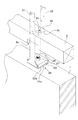
次に、本発明の第2の実施形態である柱脚部固定構造について説明する。
図6はこの柱脚部固定構造を示す側面図であり、図7は同じ柱脚部固定構造の断面図である。また、図8は概略斜視図である。
この構造では、ホールダウン部材の柱接合部31が、柱3の2つの側面にそれぞれ取り付けられた取り付け金具32と、これらの取り付け金具32に係止された連結ボルト33とを有するものとなっている。また、連結ボルト33の下端部を互いに連結する下端連結部は、基礎の上部に埋め込まれた鋼からなる連結部材34によって構成されている。そして、この連結部材34がアンカーボルト35によって基礎1に固定される。
Next, the column base part fixing structure which is the 2nd Embodiment of this invention is demonstrated.
FIG. 6 is a side view showing the column base fixing structure, and FIG. 7 is a cross-sectional view of the same column base fixing structure. FIG. 8 is a schematic perspective view.
In this structure, the column
上記柱接合部の取り付け金具32は、柱3の側面に当接される鋼プレート32aと、この鋼プレート32aから突出するように設けられて連結ボルト33が係止される係止部32bとを有するものである。鋼プレート32aは固定ボルト36によって柱3に固定されるものとなっており、固定ボルト36は柱3をほぼ水平に貫通し、ほぼ平行となった柱3の2つの側面にそれぞれ取り付け金具32を固定するものとなっている。
連結ボルト33は両端部に雄ねじが形成されたものであり、上端部に設けられた雄ねじにはナット37が螺合され、このナット37が取り付け金具32の係止部32bに係止される。連結ボルト33の下端部に形成された雄ねじは、連結部材34に設けられたボルト穴にねじ込んで連結されるものとなっている。
The mounting
The connecting
上記連結部材34は、鋼からなるブロック状の部材であり、上面が基礎1の上面とほぼ同じ高さでほぼ水平となって露出するように基礎1のコンクリート内に埋め込まれている。この連結部材34は、図7及び図8に示すように耐力壁の壁面と直角方向の寸法が柱3及び土台2の寸法(土台の幅)より大きくなっており、基礎1上に土台2を配置し、その上に柱3を立設したときに、土台2の側方で連結部材34が露出するものとなっている。この連結部材34の端部付近つまり土台2の側方に露出した部分に鉛直方向のボルト穴が設けられており、このボルト穴に上記連結ボルト33の下端部が螺合される。
なお、壁面を形成する内装材39又は外装材40は、上記取り付け金具32及び連結ボルト33を覆うように設けることができる。
The connecting
The
一方、連結部材34の下面には、耐力壁の壁面と直角方向のほぼ中央部に、鉛直方向のボルト穴が形成されている。そして、このボルト穴に下側からアンカーボルト35をねじ込んで接合されている。このアンカーボルト35は基礎1のコンクリート内に埋め込まれ、下端部は断面拡大部、フック等が設けられて引き抜き抵抗が大きくなっている。
On the other hand, a vertical bolt hole is formed on the lower surface of the connecting
なお、上記連結部材34は、壁面と直角方向の立面で見たときの形状が、図7に示すように上部が矩形で下方では幅を縮小するものとなっている。しかし、連結部材はこのような形状に限定されるものではなく、壁面と直角方向の両端部が柱接合部31と連結することができるように露出され、下部は基礎1のコンクリートに埋め込まれたアンカーボルト35と結合することができる形状であれば様々な形状とすることができる。また、側面形状も図6に示すような矩形となるものに限定されるものではない。
また、基礎1は壁面と直角方向の寸法が、図8に示すように土台2の幅より大きく設定され、連結部材34の壁面と直角方向の寸法とほぼ同じとなっているが、連結部材34の寸法より大きいもの又は小さいものであってもよい。
The connecting
Further, the
土台2は、基礎1上に耐力壁の壁面に沿った方向に配置され、連結部材34がコンクリートに埋め込まれた位置の両側に連続するものである。そして、柱3が立設される位置には上面から鉛直下方に向けてほぞ穴が形成され、その周辺に柱支持部材38を貫入するための貫通孔が設けられている。
柱支持部材38は、鋼からなる棒状部38aとその下端に水平方向に取り付けられた鋼板38bとを有するものであり、土台2に設けられた貫通孔に下側から棒状部38aが挿入されている。鋼板38bは土台2の下面に形成された切り欠き内に嵌め入れられ、下面が土台2の下面とほぼ同じ高さとなっている。このとき棒状部38aの上端面は土台2の上面とほぼ同じ高さとなるように棒状部38aの長さが設定されている。
The
The
土台2の上には、鋼板材によって形成されたは柱支持板11が載置され、この上に柱3が立設される。柱支持板11には中央部に開口が形成されており、柱3の下端から突き出すように設けられた「ほぞ」3cが上記開口に挿通され、土台2に形成されたほぞ穴に嵌めいれられている。
A
このような柱脚部固定構造では、アンカーボルト35及び連結部材34を基礎1の形成時にコンクリートへ埋め込み、土台2及び柱3を設置した後に連結ボルト33を取り付けて、基礎1上に柱3及び土台2を容易に固定することができる。また、柱3上の負荷が増加して柱3が下方に変位した場合にも、連結ボルト33を取り付け金具32に係止する位置でナット37を締め付け、柱3に上揚力が作用する初期から有効に柱3を拘束することが可能となる。
In such a column base fixing structure, the
そして、柱3に上揚力が作用したときに、基礎1からアンカーボルト35、連結部材34、連結ボルト33及び取り付け金具32によって主要部が構成されるホールダウン部材31によって柱3が拘束され、上方へ引き抜くように変位するのが抑制される。また、上方への力がホールダウン部材31によって基礎1に伝達されるときに、2つの取り付け金具32及び連結ボルト33に分散されても合力は壁体の中心に線に沿った位置に作用しており、安定した状態で基礎に伝達される。
When the lifting force is applied to the
一方、柱3に鉛直下方への圧縮力が作用するときには柱支持板11から柱支持部材38を介して基礎1のコンクリートに力が伝達され、土台2に大きな負荷をかけることなく柱3が支持される。したがって、柱3に鉛直方向の大きな変位が生じるのを抑えることができる。
また、基礎1と土台2との間及び土台2と柱3との間に生じる水平方向の力に対しては、図1に示す耐力壁と同様に土台2が複数のアンカーボルトによって基礎上に固定され、柱3は「ほぞ」を土台2のほぞ穴に嵌め入れることによって水平方向の変位が拘束される。
On the other hand, when a vertically downward compressive force is applied to the
Moreover, with respect to the horizontal force generated between the
なお、上記柱接合部31の取り付け金具32は、図6及び図7に示すように柱3の2つの側面のそれぞれに一つずつを取り付けているが、図8に示すように柱3の2つの側面のそれぞれに2つずつを上下に取り付けることもできる。このときには、下側に取り付けた第1の取り付け金具32−1に第1の連結ボルト33−1を係止し、この第1の連結ボルト33−1の上端部に接続具41を螺合して第2の連結ボルト33−2と接続する。そして、第2の連結ボルト33−2の上端部を上側に取り付けられた第2の取り付け金具32−2に係止することができる。このように取り付け金具32を上下に2つ設けることにより、柱3と取り付け金具32との間に作用する力を分散することができ、耐力壁の耐荷力を増大することができる。
In addition, as for the attachment metal fitting 32 of the said
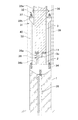
次に、本発明の第3の実施形態である柱脚部固定構造について説明する。
図9は、この柱脚部固定構造を示す側面図であり、図10は断面図である。
この構造では、ホールダウン部材51が、柱3の2つの側面にそれぞれ取り付けられた取り付け金具52と、これらの取り付け金具52に係止された連結ボルト53と、この連結ボルト53の下端に接続される連結プレート54と、基礎1のコンクリート内に埋め込まれ、コンクリートから露出した両端部に連結プレート53が接合される連結部材55とで主要部が構成されている。
Next, a column base fixing structure which is a third embodiment of the present invention will be described.
FIG. 9 is a side view showing this column base fixing structure, and FIG. 10 is a cross-sectional view.
In this structure, the hole-
上記取り付け金具52及び連結ボルト53は、図6及び図7に示す実施の形態と同じものを用いることができ、連結プレート54とともに本発明の柱接合部を形成している。
上記連結プレート54は、上端に袋ナット状の接続具56が溶接で固着された鋼の帯状の部材であり、下端部には連結部材55と接続するためのボルト孔が形成されている。上記連結ボルト53は上端部が取り付け金具52に係止されるとともに、下端部が上記袋ナット状の接続具56にねじり合わせて接続される。
The mounting
The connecting
上記連結部材55は、鋼からなる棒状の部材であって、その長さが壁状となった基礎1の厚さとほぼ同じ長さとなっており、両端面から軸線方向にボルト穴が形成されている。この連結部材55は、柱3が立設される位置で基礎1の上面より下方に、軸線を水平方向にしてコンクリート中に埋め込まれている。そして両端面が壁状となった基礎1の両側面に露出している。
The connecting member 55 is a rod-shaped member made of steel, the length of which is almost the same as the thickness of the
上記連結プレート54は、基礎1の上面より上方で連結ボルト53と接続され、基礎1の側面に沿って下方に配置されて、下端部のボルト孔に挿通したボルト57を連結部材55の上記ボルト穴にねじ込み、締め付けて固定される。
これにより、連結部材55が基礎1のコンクリート中に埋め込んで固定されるともに、連結部材55、連結プレート54、連結ボルト53及び取り付け金具52を介して柱3に連結され、柱3に上揚力が作用したときにも、柱3が上方に引き上げられないように拘束するものとなっている。
上記基礎1の連結部材55が埋め込まれた位置の周辺部には、コンクリート中に配置される水平方向の鉄筋58及び鉛直方向の鉄筋59の他に、補強用の鉄筋(図示しない)を配置することもできる。
The
As a result, the connecting member 55 is embedded and fixed in the concrete of the
In the periphery of the position where the connecting member 55 of the
また、土台2は基礎1上に耐力壁の壁面に沿った方向に配置され、図6及び図7に示す実施の形態で使用されたものと同じ柱支持部材60が装着される。また、図6及び図7に示す実施の形態で使用されたものと同じ柱支持板61が土台2の上に載置され、この上に柱3が立設される。柱3には「ほぞ」3cが形成されており、柱支持板61の開口に挿通して土台2に設けられたほぞ穴に嵌め入れられている。
The
このような柱脚部固定構造でも、土台2及び柱3を設置した後に連結ボルト53及び連結プレート54を取り付けて、基礎1上に柱3及び土台2を容易に固定することができる。そして、柱3に上揚力が作用したときに、基礎1から連結部材55、連結プレート54、連結ボルト53及び取り付け金具52によって主要部が構成されるホールダウン部材51によって柱3を拘束することができる。
Even in such a column base fixing structure, the
なお、本発明は以上に説明した実施の形態に限定されるものではなく、本発明の範囲内において、使用部材の形態、材料等を適宜に変更して実施することができる。 In addition, this invention is not limited to embodiment described above, In the range of this invention, the form of a use member, material, etc. can be changed suitably and can be implemented.
1:基礎, 2:土台, 3:柱, 4:横架材, 5:胴つなぎ材, 6:合板, 7:アンカーボルト, 8:ナット, 9:ホールダウン部材,
11:柱支持板, 12:押さえ金具,
21,22:柱接合部, 23:連結部材, 24:アンカーボルト, 25:ビス, 26:下端連結部, 27:ナット, 28:柱支持部材,
31:ホールダウン部材, 32:取り付け金具, 33:連結ボルト, 34:連結部材, 35:アンカーボルト, 36:固定ボルト, 37:ナット, 38:柱支持部材, 39:内装材, 40:外装材, 41:接続具,
51:ホールダウン部材, 52:取り付け金具, 53:連結ボルト, 54:連結プレート, 55:連結部材, 56:接続具, 57:ボルト, 58:水平方向の鉄筋, 59:鉛直方向の鉄筋, 60:柱支持部材, 61:柱支持板
1: foundation, 2: base, 3: pillar, 4: horizontal member, 5: torso, 6: plywood, 7: anchor bolt, 8: nut, 9: hole down member,
11: Column support plate, 12: Presser bracket,
21 and 22: column joint portion, 23: connecting member, 24: anchor bolt, 25: screw, 26: lower end connecting portion, 27: nut, 28: column supporting member,
31: Hole-down member, 32: Mounting bracket, 33: Connection bolt, 34: Connection member, 35: Anchor bolt, 36: Fixing bolt, 37: Nut, 38: Column support member, 39: Interior material, 40: Exterior material , 41: connection tool,
51: Hole-down member, 52: Mounting bracket, 53: Connection bolt, 54: Connection plate, 55: Connection member, 56: Connector, 57: Bolt, 58: Horizontal rebar, 59: Vertical rebar, 60 : Column support member, 61: Column support plate
Claims (6)
該土台上に立設された木材からなる柱と、
該柱に作用する上揚力を前記基礎に伝達して該柱が浮き上がるのを抑えるホールダウン部材と、を有する柱脚部固定構造であって、
前記ホールダウン部材は、前記柱の前記壁面とほぼ平行となった2つの側面にそれぞれ接合された2つの柱接合部と、該柱の下端面より下方で2つの前記柱接合部を互いに連結する下端連結部と、を有し、
2つの前記柱接合部と前記下端連結部と前記柱とが前記土台を囲むように連結されており、
該下端連結部が前記基礎に固定されていることを特徴とする柱脚部固定構造。 A base made of wood fixedly supported on a concrete foundation formed along the direction of the wall surface of the wooden building;
A pillar made of wood erected on the foundation;
A column base fixing structure having a hole-down member that transmits an uplift force acting on the column to the foundation to prevent the column from floating,
The hole-down member connects two column joints joined to two side surfaces substantially parallel to the wall surface of the column, and the two column joints below the lower end surface of the column. A lower end connecting portion,
The two column junctions, the lower end coupling portion and the column are coupled so as to surround the base;
The column base portion fixing structure, wherein the lower end connecting portion is fixed to the foundation.
前記柱接合部が該連結部材に接合され、2つの前記柱接合部と前記連結部材と前記柱とが前記土台を囲むように連結されており、
前記連結部材に結合されたアンカー部材が前記基礎に埋め込まれていることを特徴とする請求項1に記載の柱脚部固定構造。 The lower end connecting portion has a connecting member made of steel provided on the lower side of the base,
The column joint portion is joined to the connecting member, and the two column joint portions, the connecting member, and the column are connected so as to surround the base,
The column base fixing structure according to claim 1, wherein an anchor member coupled to the connecting member is embedded in the foundation.
前記連結部材は、前記基礎上で水平方向に支持された鋼からなる板状の部材であり、
前記柱の下端は、前記土台上に載置された柱支持板を介して該土台上に支持されており、
前記土台を貫通し、上端が前記柱支持板の下面に当接され、下端が前記連結部材に当接
された柱支持部材を有することを特徴とする請求項2に記載の柱脚部固定構造。 The column joint is formed of a plate material made of steel,
The connecting member is a plate-like member made of steel supported in the horizontal direction on the foundation,
The lower end of the column is supported on the base via a column support plate placed on the base,
The column base fixing structure according to claim 2, further comprising a column support member that penetrates through the base, has an upper end abutted against a lower surface of the column support plate, and a lower end abutted against the connecting member. .
該土台上に立設された木材からなる柱と、
該柱に作用する上揚力を前記基礎に伝達して該柱が浮き上がるのを抑えるホールダウン部材と、を有する柱脚部固定構造であって、
前記ホールダウン部材は、前記柱の前記壁面とほぼ平行となった2つの側面にそれぞれ接合された2つの柱接合部と、該柱の下端面より下方で2つの前記柱接合部を互いに連結する下端連結部と、を有し、
該下端連結部が前記基礎に固定されており、
該下端連結部は、前記基礎上に支持された連結部材又は前記基礎の上部に埋め込まれた連結部材を有し、
前記柱接合部の下端部に形成された雄ねじ部を、前記連結部材の壁面と直角方向の両端部に設けられたねじ穴に螺合することによって該連結部材と結合されていることを特徴とする柱脚部固定構造。 A base made of wood fixedly supported on a concrete foundation formed along the direction of the wall surface of the wooden building;
A pillar made of wood erected on the foundation;
A column base fixing structure having a hole-down member that transmits an uplift force acting on the column to the foundation to prevent the column from floating,
The hole-down member connects two column joints joined to two side surfaces substantially parallel to the wall surface of the column, and the two column joints below the lower end surface of the column. A lower end connecting portion,
The lower end connecting portion is fixed to the foundation;
The lower end connecting part has a connecting member supported on the foundation or a connecting member embedded in the upper part of the foundation,
The male screw portion formed at the lower end portion of the column joint portion is coupled to the connecting member by screwing into a screw hole provided at both end portions in a direction perpendicular to the wall surface of the connecting member. Column base fixing structure.
該土台上に立設された木材からなる柱と、
該柱に作用する上揚力を前記基礎に伝達して該柱が浮き上がるのを抑えるホールダウン部材と、を有する柱脚部固定構造であって、
前記ホールダウン部材は、前記柱の前記壁面とほぼ平行となった2つの側面にそれぞれ接合された2つの柱接合部と、該柱の下端面より下方で2つの前記柱接合部を互いに連結する下端連結部と、を有し、
該下端連結部が前記基礎に固定されており、
該下端連結部は、前記基礎の上面より下方において該基礎に埋め込まれ、前記壁面と直角方向の両端部が該基礎の鉛直面に露出した連結部材を有し、
前記柱接合部は、柱の側面及び前記基礎の鉛直面に沿って配置され、前記連結部材の前記基礎から露出した端部に結合されていることを特徴とする柱脚部固定構造。 A base made of wood fixedly supported on a concrete foundation formed along the direction of the wall surface of the wooden building;
A pillar made of wood erected on the foundation;
A column base fixing structure having a hole-down member that transmits an uplift force acting on the column to the foundation to prevent the column from floating,
The hole-down member connects two column joints joined to two side surfaces substantially parallel to the wall surface of the column, and the two column joints below the lower end surface of the column. A lower end connecting portion,
The lower end connecting portion is fixed to the foundation;
The lower end connecting portion is embedded in the foundation below the upper surface of the foundation, and has a connecting member in which both end portions in a direction perpendicular to the wall surface are exposed on the vertical surface of the foundation,
The column base portion fixing structure, wherein the column joint portion is disposed along a side surface of the column and a vertical surface of the foundation, and is coupled to an end portion exposed from the foundation of the connection member.
該柱支持板の下側には、前記土台を上下方向に貫通し、該柱支持板から基礎に上方からの力を伝達する柱支持部材を有することを特徴とする請求項4又は請求項5に記載の柱脚部固定構造。 The lower end of the column is supported via a column support plate disposed on the upper side of the base,
6. The column support plate according to claim 4, further comprising a column support member that passes through the base in a vertical direction and transmits a force from above to the foundation from the column support plate. Column base fixing structure described in 1.
Priority Applications (1)
| Application Number | Priority Date | Filing Date | Title |
|---|---|---|---|
| JP2013184111A JP6247057B2 (en) | 2013-09-05 | 2013-09-05 | Column base fixing structure |
Applications Claiming Priority (1)
| Application Number | Priority Date | Filing Date | Title |
|---|---|---|---|
| JP2013184111A JP6247057B2 (en) | 2013-09-05 | 2013-09-05 | Column base fixing structure |
Publications (2)
| Publication Number | Publication Date |
|---|---|
| JP2015052203A JP2015052203A (en) | 2015-03-19 |
| JP6247057B2 true JP6247057B2 (en) | 2017-12-13 |
Family
ID=52701406
Family Applications (1)
| Application Number | Title | Priority Date | Filing Date |
|---|---|---|---|
| JP2013184111A Active JP6247057B2 (en) | 2013-09-05 | 2013-09-05 | Column base fixing structure |
Country Status (1)
| Country | Link |
|---|---|
| JP (1) | JP6247057B2 (en) |
Family Cites Families (3)
| Publication number | Priority date | Publication date | Assignee | Title |
|---|---|---|---|---|
| US3413773A (en) * | 1966-10-07 | 1968-12-03 | Gerald A. Fitzgerald | Saddle anchor |
| JPS63251547A (en) * | 1987-04-07 | 1988-10-19 | 旭化成株式会社 | Structure of connection part between principle members |
| JP3661794B2 (en) * | 2002-08-30 | 2005-06-22 | 株式会社東栄住宅 | Structural hardware |
-
2013
- 2013-09-05 JP JP2013184111A patent/JP6247057B2/en active Active
Also Published As
| Publication number | Publication date |
|---|---|
| JP2015052203A (en) | 2015-03-19 |
Similar Documents
| Publication | Publication Date | Title |
|---|---|---|
| JP6227452B2 (en) | Wall pillar structure | |
| US10829926B2 (en) | Metal joint and panel joining method | |
| JP4799107B2 (en) | Mouth structure of wooden structure material, horizontal member, column base structure and column base metal fittings, wooden frame having the same and method of assembling the same | |
| US11168473B2 (en) | Metal restraint strap and structural body restraining method | |
| JP6247057B2 (en) | Column base fixing structure | |
| JP6445963B2 (en) | Connector | |
| JP5002569B2 (en) | Gate-type frame structure of a wooden building | |
| JP2008138493A (en) | Aseismatic reinforcing metal fittings for wooden building | |
| JP6667273B2 (en) | Mounting structure of tension rod | |
| JP5491070B2 (en) | Seismic reinforcement members and earthquake-resistant buildings | |
| JP5358203B2 (en) | Building unit fixed structure and unit building | |
| JP7399344B2 (en) | Wall structure of simple structure and simple structure | |
| JP2009275356A (en) | Building reinforcing metal | |
| JP7169177B2 (en) | Structure with damping device | |
| KR100970942B1 (en) | steel structure | |
| JPH0762371B2 (en) | Composite beam for frame structure | |
| JPH0978694A (en) | Earthquake resistant reinforcing metal fittings of building | |
| JP3739372B2 (en) | Bracing structure in wooden buildings | |
| JP3851052B2 (en) | Building structure reinforcing bracket and method for reinforcing building structure | |
| JP2005213902A (en) | Mounting structure of brace | |
| JP5707455B2 (en) | Fastening structure for members | |
| JP2014118801A (en) | Aseismatic reinforcement structure of wooden house | |
| JP4958096B2 (en) | Seismic steel frame for wooden | |
| JP2005030004A (en) | Woody reinforcing structural member and reinforcing structure for building | |
| JP2021161631A (en) | Joint structure for woody shaft member |
Legal Events
| Date | Code | Title | Description |
|---|---|---|---|
| A621 | Written request for application examination |
Free format text: JAPANESE INTERMEDIATE CODE: A621 Effective date: 20160721 |
|
| A977 | Report on retrieval |
Free format text: JAPANESE INTERMEDIATE CODE: A971007 Effective date: 20170512 |
|
| A131 | Notification of reasons for refusal |
Free format text: JAPANESE INTERMEDIATE CODE: A131 Effective date: 20170523 |
|
| A521 | Request for written amendment filed |
Free format text: JAPANESE INTERMEDIATE CODE: A523 Effective date: 20170703 |
|
| TRDD | Decision of grant or rejection written | ||
| A01 | Written decision to grant a patent or to grant a registration (utility model) |
Free format text: JAPANESE INTERMEDIATE CODE: A01 Effective date: 20171109 |
|
| A61 | First payment of annual fees (during grant procedure) |
Free format text: JAPANESE INTERMEDIATE CODE: A61 Effective date: 20171116 |
|
| R150 | Certificate of patent or registration of utility model |
Ref document number: 6247057 Country of ref document: JP Free format text: JAPANESE INTERMEDIATE CODE: R150 |
|
| R250 | Receipt of annual fees |
Free format text: JAPANESE INTERMEDIATE CODE: R250 |
|
| R250 | Receipt of annual fees |
Free format text: JAPANESE INTERMEDIATE CODE: R250 |