JP6246545B2 - Suspension device - Google Patents

Suspension device Download PDF

Info

Publication number
JP6246545B2
JP6246545B2 JP2013209723A JP2013209723A JP6246545B2 JP 6246545 B2 JP6246545 B2 JP 6246545B2 JP 2013209723 A JP2013209723 A JP 2013209723A JP 2013209723 A JP2013209723 A JP 2013209723A JP 6246545 B2 JP6246545 B2 JP 6246545B2
Authority
JP
Japan
Prior art keywords
space
cap
cylindrical portion
inner tube
piston
Prior art date
Legal status (The legal status is an assumption and is not a legal conclusion. Google has not performed a legal analysis and makes no representation as to the accuracy of the status listed.)
Active
Application number
JP2013209723A
Other languages
Japanese (ja)
Other versions
JP2015075133A (en
JP2015075133A5 (en
Inventor
吉田 耕二郎
耕二郎 吉田
Current Assignee (The listed assignees may be inaccurate. Google has not performed a legal analysis and makes no representation or warranty as to the accuracy of the list.)
Showa Corp
Original Assignee
Showa Corp
Priority date (The priority date is an assumption and is not a legal conclusion. Google has not performed a legal analysis and makes no representation as to the accuracy of the date listed.)
Filing date
Publication date
Application filed by Showa Corp filed Critical Showa Corp
Priority to JP2013209723A priority Critical patent/JP6246545B2/en
Priority to US14/258,328 priority patent/US9541152B2/en
Priority to EP14165782.5A priority patent/EP2865588B1/en
Publication of JP2015075133A publication Critical patent/JP2015075133A/en
Publication of JP2015075133A5 publication Critical patent/JP2015075133A5/ja
Application granted granted Critical
Publication of JP6246545B2 publication Critical patent/JP6246545B2/en
Active legal-status Critical Current
Anticipated expiration legal-status Critical

Links

Images

Classifications

    • FMECHANICAL ENGINEERING; LIGHTING; HEATING; WEAPONS; BLASTING
    • F16ENGINEERING ELEMENTS AND UNITS; GENERAL MEASURES FOR PRODUCING AND MAINTAINING EFFECTIVE FUNCTIONING OF MACHINES OR INSTALLATIONS; THERMAL INSULATION IN GENERAL
    • F16FSPRINGS; SHOCK-ABSORBERS; MEANS FOR DAMPING VIBRATION
    • F16F9/00Springs, vibration-dampers, shock-absorbers, or similarly-constructed movement-dampers using a fluid or the equivalent as damping medium
    • F16F9/32Details
    • F16F9/34Special valve constructions; Shape or construction of throttling passages
    • F16F9/341Special valve constructions; Shape or construction of throttling passages comprising noise-reducing or like features, e.g. screens
    • BPERFORMING OPERATIONS; TRANSPORTING
    • B62LAND VEHICLES FOR TRAVELLING OTHERWISE THAN ON RAILS
    • B62KCYCLES; CYCLE FRAMES; CYCLE STEERING DEVICES; RIDER-OPERATED TERMINAL CONTROLS SPECIALLY ADAPTED FOR CYCLES; CYCLE AXLE SUSPENSIONS; CYCLE SIDE-CARS, FORECARS, OR THE LIKE
    • B62K25/00Axle suspensions
    • B62K25/04Axle suspensions for mounting axles resiliently on cycle frame or fork
    • B62K25/06Axle suspensions for mounting axles resiliently on cycle frame or fork with telescopic fork, e.g. including auxiliary rocking arms
    • B62K25/08Axle suspensions for mounting axles resiliently on cycle frame or fork with telescopic fork, e.g. including auxiliary rocking arms for front wheel
    • FMECHANICAL ENGINEERING; LIGHTING; HEATING; WEAPONS; BLASTING
    • F16ENGINEERING ELEMENTS AND UNITS; GENERAL MEASURES FOR PRODUCING AND MAINTAINING EFFECTIVE FUNCTIONING OF MACHINES OR INSTALLATIONS; THERMAL INSULATION IN GENERAL
    • F16FSPRINGS; SHOCK-ABSORBERS; MEANS FOR DAMPING VIBRATION
    • F16F9/00Springs, vibration-dampers, shock-absorbers, or similarly-constructed movement-dampers using a fluid or the equivalent as damping medium
    • F16F9/10Springs, vibration-dampers, shock-absorbers, or similarly-constructed movement-dampers using a fluid or the equivalent as damping medium using liquid only; using a fluid of which the nature is immaterial
    • F16F9/14Devices with one or more members, e.g. pistons, vanes, moving to and fro in chambers and using throttling effect
    • F16F9/16Devices with one or more members, e.g. pistons, vanes, moving to and fro in chambers and using throttling effect involving only straight-line movement of the effective parts
    • F16F9/18Devices with one or more members, e.g. pistons, vanes, moving to and fro in chambers and using throttling effect involving only straight-line movement of the effective parts with a closed cylinder and a piston separating two or more working spaces therein
    • F16F9/185Bitubular units
    • FMECHANICAL ENGINEERING; LIGHTING; HEATING; WEAPONS; BLASTING
    • F16ENGINEERING ELEMENTS AND UNITS; GENERAL MEASURES FOR PRODUCING AND MAINTAINING EFFECTIVE FUNCTIONING OF MACHINES OR INSTALLATIONS; THERMAL INSULATION IN GENERAL
    • F16FSPRINGS; SHOCK-ABSORBERS; MEANS FOR DAMPING VIBRATION
    • F16F9/00Springs, vibration-dampers, shock-absorbers, or similarly-constructed movement-dampers using a fluid or the equivalent as damping medium
    • F16F9/10Springs, vibration-dampers, shock-absorbers, or similarly-constructed movement-dampers using a fluid or the equivalent as damping medium using liquid only; using a fluid of which the nature is immaterial
    • F16F9/14Devices with one or more members, e.g. pistons, vanes, moving to and fro in chambers and using throttling effect
    • F16F9/16Devices with one or more members, e.g. pistons, vanes, moving to and fro in chambers and using throttling effect involving only straight-line movement of the effective parts
    • F16F9/22Devices with one or more members, e.g. pistons, vanes, moving to and fro in chambers and using throttling effect involving only straight-line movement of the effective parts with one or more cylinders each having a single working space closed by a piston or plunger
    • FMECHANICAL ENGINEERING; LIGHTING; HEATING; WEAPONS; BLASTING
    • F16ENGINEERING ELEMENTS AND UNITS; GENERAL MEASURES FOR PRODUCING AND MAINTAINING EFFECTIVE FUNCTIONING OF MACHINES OR INSTALLATIONS; THERMAL INSULATION IN GENERAL
    • F16FSPRINGS; SHOCK-ABSORBERS; MEANS FOR DAMPING VIBRATION
    • F16F9/00Springs, vibration-dampers, shock-absorbers, or similarly-constructed movement-dampers using a fluid or the equivalent as damping medium
    • F16F9/32Details
    • F16F9/43Filling or drainage arrangements, e.g. for supply of gas

Description

本発明は、二輪車等の車体と車輪との間に配置される懸架装置に関する。   The present invention relates to a suspension device disposed between a vehicle body such as a motorcycle and wheels.

従来、懸架装置の一例としての二輪車のフロントフォークには、アウタチューブの内周の上下にブッシュを固定し、この上下のブッシュを介してインナチューブを摺動自在に嵌合して、アウタチューブの内周とインナチューブの外周との間の空間に、上下のブッシュにより区画された環状の油室である環状油室を形成することで、ストローク時のピストンロッドの進入/退出分の容積補償室を形成するものが知られている。   Conventionally, on a front fork of a motorcycle as an example of a suspension device, bushes are fixed to the upper and lower sides of the inner periphery of the outer tube, and an inner tube is slidably fitted through the upper and lower bushes. By forming an annular oil chamber that is an annular oil chamber partitioned by upper and lower bushes in the space between the inner periphery and the outer periphery of the inner tube, the volume compensation chamber for the entry / exit of the piston rod during the stroke Are known.

そして、特許文献1に記載の油圧緩衝器は、この種の懸架装置において、インナチューブの開口端側の内部に、アウタチューブに取り付けられたピストンロッドを案内するための隔壁部材が取り付けられている。隔壁部材は、インナチューブの内周に沿う筒状に形成された筒部と、この筒部の底を閉塞するように設けられた底部とにより構成され、筒部をインナチューブに螺合させて取り付けることで、底部をインナーチューブの内部に位置させ、当該底部を基準として、その下方をアウタチューブに固定されたピストンロッドに取り付けられたピストンが摺動する作動油室、その上方を作動油室に作動油を給排するための油溜室に区画している。この作動油室は、インナチューブに設けられた油孔によって上記環状油室に対して連通し、作動油の流通が自在とされており、油圧緩衝器の圧縮時には、作動油室内にストローク分進入したピストンロッドの容積分の作動油が作動油室から環状油室に流出し、伸張時には、作動油室からストローク分退出したピストンロッドの容積分の作動油が環状油室から作動油室に流入することで、ピストンロッドの進入/退出分の容積補償がなされ、所定の減衰力を得るようにしている。また、この特許文献1に記載の油圧緩衝器は、アウタチューブの上端開口部に封着されるキャップに複数の調整部を設け、複数の調整部がキャップの平面視で、互いに並置されている。複数の調整部のそれぞれは、アジャストボルトからなるとともに、各アジャストボルト毎に対応する複数のアジャストナットを付帯的に有し、各アジャストナットは対応するアジャストボルトが螺合するねじ孔と、他のアジャストボルトが挿通するガイド孔を備え、各アジャストボルトの回転操作により、このアジャストボルトが螺合しているアジャストナットは、当該アジャストナットのガイド孔と他のアジャストボルトとの係合を介して回り止めかつ軸方向に移動ガイドされ、軸方向に移動するように構成されている。   In the hydraulic shock absorber described in Patent Document 1, in this type of suspension device, a partition member for guiding a piston rod attached to the outer tube is attached inside the opening end side of the inner tube. . The partition member is composed of a cylindrical portion formed in a cylindrical shape along the inner periphery of the inner tube and a bottom portion provided so as to close the bottom of the cylindrical portion, and the cylindrical portion is screwed to the inner tube. By mounting, the bottom is positioned inside the inner tube, and with the bottom as a reference, the lower part is a hydraulic oil chamber in which the piston attached to the piston rod fixed to the outer tube slides, and the upper part is the hydraulic oil chamber It is divided into an oil reservoir chamber for supplying and discharging hydraulic oil. The hydraulic oil chamber communicates with the annular oil chamber through an oil hole provided in the inner tube so that the hydraulic oil can freely flow. When the hydraulic shock absorber is compressed, the hydraulic oil chamber enters the hydraulic oil chamber for a stroke. The hydraulic oil equivalent to the volume of the piston rod that has flowed out of the hydraulic oil chamber flows into the annular oil chamber, and when extended, the hydraulic oil equivalent to the volume of the piston rod that has retreated from the hydraulic oil chamber flows into the hydraulic oil chamber from the annular oil chamber. By doing so, volume compensation for the entry / exit of the piston rod is performed, and a predetermined damping force is obtained. In addition, the hydraulic shock absorber described in Patent Document 1 is provided with a plurality of adjustment portions on a cap sealed in the upper end opening of the outer tube, and the plurality of adjustment portions are juxtaposed with each other in a plan view of the cap. . Each of the plurality of adjusting portions is composed of an adjusting bolt and has a plurality of adjusting nuts corresponding to each adjusting bolt, and each adjusting nut has a screw hole into which the corresponding adjusting bolt is screwed, and other adjustment nuts. A guide hole through which the adjustment bolt is inserted is provided, and the adjustment nut to which the adjustment bolt is screwed by rotation of each adjustment bolt rotates through the engagement between the guide hole of the adjustment nut and another adjustment bolt. It is configured to stop and move in the axial direction and move in the axial direction.

特開2009−85263号公報JP 2009-85263 A

特許文献1に記載の懸架装置では、複数の調整部のそれぞれに設けられた複数のアジャストボルト間に、作動油内に含まれる気泡が徐々に集合して気泡溜まりとなるおそれがある。これらの部位に気泡溜まりができた場合には、伸張動作時に、気泡溜まりが作動油により圧縮された後に所定の滅衰力が得られることとなるため、減衰動作が遅れてしまう。また、作動油室の内、ピストンより下方に形成された油室への作動油の供給が遅れるため、当該油室の圧力が急減し、作動油中の気体成分が析出して気泡が成長する。そして、その後に圧縮動作が行われると、成長した気泡が瞬時に圧縮されて消滅する際に衝撃音が発生する。
本発明は、伸張動作時に圧力が高められる空気が存在する空間に気泡溜まりが発生したことに起因して衝撃音が発生することを抑制することができる懸架装置を提供することを目的とする。
In the suspension device described in Patent Document 1, bubbles contained in the hydraulic oil gradually gather between the plurality of adjustment bolts provided in each of the plurality of adjusting units, and there is a possibility that bubbles may be accumulated. When bubbles accumulate in these parts, a predetermined extinction force is obtained after the bubble reservoir is compressed with hydraulic oil during the extension operation, so that the damping operation is delayed. In addition, since the supply of the hydraulic oil to the oil chamber formed below the piston in the hydraulic oil chamber is delayed, the pressure in the oil chamber is suddenly reduced, and gas components in the hydraulic oil are deposited to grow bubbles. . Then, when a compression operation is performed thereafter, an impact sound is generated when the grown bubbles are instantaneously compressed and disappear.
An object of the present invention is to provide a suspension device that can suppress the generation of an impact sound due to the occurrence of bubble accumulation in a space in which air whose pressure is increased during an extension operation is present.

第1発明に係る懸架装置は、筒状のアウタチューブと、前記アウタチューブの内側に同軸的に配置されて当該アウタチューブと軸方向に相対的に移動するインナチューブと、前記インナチューブ内に挿入されたピストンを一方の端部に保持して、前記アウタチューブと共に当該インナチューブに対して移動する筒状のピストンロッドと、前記インナチューブにおける上側の端部に取り付けられて前記アウタチューブの内周面と当該インナチューブの外周面との間に形成された環状室の上側の端部を区画すると共に、当該インナチューブの内側に椀状に形成された椀部を有し、当該インナチューブ内の空間を、当該椀部よりも上方の空間である上方空間と下方の空間である下方空間とに区分する隔壁部材と、前記アウタチューブの上側の開口部を覆うキャップと、一方の端部が前記キャップに保持され、他方の端部に前記ピストンロッドの他方の端部を支持する支持部材と、を備え、前記インナチューブには、前記隔壁部材の下方の部位に前記環状室と前記下方空間とを連通するように貫通された貫通孔が形成され、前記ピストンロッドの内側の空間であるロッド内部空間は、前記下方空間と連通しており、前記支持部材は、筒状の部材であり、前記キャップとの間に、前記ロッド内部空間と連通した上部空間を形成し、前記キャップ及び前記支持部材の少なくともいずれかには、前記上部空間と前記上方空間とを連通する連通路が設けられており、前記キャップは、前記支持部材の上側の端面が突き当たる突当面を有し、前記連通路は、前記キャップの前記突当面から上方に凹んだ上方凹部を含んで構成され、前記キャップの前記突当面と前記支持部材の上側の端面との間に配置され、前記連通路を介して前記上部空間から前記上方空間への空気の流れを許容し、当該上方空間から当該上部空間への空気の流れを抑制する逆止弁を備えることを特徴とする。 A suspension device according to a first aspect of the present invention includes a cylindrical outer tube, an inner tube that is coaxially disposed inside the outer tube and moves relative to the outer tube in the axial direction, and is inserted into the inner tube. A cylindrical piston rod that moves with respect to the inner tube together with the outer tube, and an inner periphery of the outer tube that is attached to the upper end of the inner tube. The upper end of the annular chamber formed between the surface and the outer peripheral surface of the inner tube, and has a flange portion formed in a bowl shape inside the inner tube, A partition member that divides the space into an upper space that is a space above the flange and a lower space that is a space below, and an opening on the upper side of the outer tube A cap that covers the first end of the piston rod, and a support member that supports the other end of the piston rod at the other end. A through-hole penetrating the annular chamber and the lower space is formed in a part, and a rod inner space that is an inner space of the piston rod communicates with the lower space, and the support member Is a cylindrical member, and forms an upper space communicating with the rod internal space between the cap and at least one of the cap and the support member, the upper space and the upper space, and the communication passage is provided for communicating, said cap has an end face abuts abutment surface of an upper side of the supporting member, wherein the communication passage is recessed upwardly from the abutment surface of the cap A concave portion is disposed between the abutment surface of the cap and the upper end surface of the support member, and allows air to flow from the upper space to the upper space via the communication path. A check valve that suppresses the flow of air from the upper space to the upper space is provided .

発明に係る懸架装置は、前記ピストンは、前記下方空間を、上方に位置する空間である上方位置空間と、下方に位置する空間である下方位置空間とに区分する区分部材を保持すると共に、当該上方位置空間と当該下方位置空間とを連通する孔である空間連通孔が形成されており、前記ピストンの前記空間連通孔を通過する流体の量を調整する調整機構をさらに備え、前記上部空間の内部には、前記調整機構を操作する操作部が配置されていることを特徴とする。 In the suspension device according to a second aspect of the invention, the piston holds a dividing member that divides the lower space into an upper position space that is an upper space and a lower position space that is a lower space. A space communication hole that is a hole that communicates the upper position space and the lower position space, and further includes an adjustment mechanism that adjusts the amount of fluid that passes through the space communication hole of the piston. An operation unit for operating the adjusting mechanism is arranged inside the space.

第1発明によれば、インナチューブには、隔壁部材の下方の部位に環状室と下方空間とを連通するように貫通された貫通孔が形成され、ピストンロッドの内側の空間であるロッド内部空間は、下方空間と連通しており、支持部材は、筒状の部材であり、キャップとの間に、ロッド内部空間と連通した上部空間を形成し、キャップ及び支持部材の少なくともいずれかには、上部空間と上方空間とを連通する連通路が設けられている。このため、伸張動作時に圧力が高められる空気が存在する空間に気泡溜まりが発生したことに起因して衝撃音が発生することを抑制することができる。   According to the first aspect of the present invention, the inner tube is formed with a through hole penetrating the annular chamber and the lower space so as to communicate with the lower space of the partition wall member, and is a space inside the piston rod. Is communicated with the lower space, the support member is a cylindrical member, and forms an upper space communicating with the rod inner space between the cap and at least one of the cap and the support member, A communication path that connects the upper space and the upper space is provided. For this reason, it is possible to suppress the generation of an impact sound due to the occurrence of bubble accumulation in the space where the air whose pressure is increased during the extension operation exists.

第2発明によれば、キャップは、支持部材の上側の端面が突き当たる突当面を有し、連通路は、キャップの突当面から上方に凹んだ上方凹部を含んで構成され、キャップの突当面と支持部材の上側の端面との間に配置され、連通路を介して上部空間から上方空間への空気の流れを許容し、上方空間から上部空間への空気の流れを抑制する逆止弁を備えるため、伸張動作時に圧力が高められる空気が存在する空間から気泡を排出することができるとともに圧縮動作時に空気を吸い込むことを抑制することができる。   According to the second invention, the cap has an abutting surface against which the upper end surface of the support member abuts, and the communication path is configured to include an upper concave portion that is recessed upward from the abutting surface of the cap, A check valve is provided between the upper end surface of the support member and allows a flow of air from the upper space to the upper space through the communication path and suppresses a flow of air from the upper space to the upper space. Therefore, it is possible to discharge bubbles from a space where there is air whose pressure is increased during the extension operation, and it is possible to suppress inhalation of air during the compression operation.

第3発明によれば、連通路は、支持部材におけるキャップの下方の部位に形成された上部空間と上方空間とを連通する連通孔であり、支持部材の周囲における上方空間内には、ゴムが配置されているため、伸張動作時に圧力が高められる空気が存在する空間から気泡を排出することができるとともに圧縮動作時に空気を吸い込むことを抑制することができる。   According to the third aspect of the present invention, the communication path is a communication hole that communicates the upper space formed in the lower portion of the cap of the support member with the upper space, and rubber is contained in the upper space around the support member. Since it is arranged, it is possible to discharge the bubbles from the space where the air whose pressure is increased during the extension operation exists, and to suppress the intake of the air during the compression operation.

第4発明によれば、ピストンは、下方空間を、上方に位置する空間である上方位置空間と、下方に位置する空間である下方位置空間とに区分する区分部材を保持すると共に、上方位置空間と下方位置空間とを連通する孔である空間連通孔が形成されており、ピストンの空間連通孔を通過する流体の量を調整する調整機構をさらに備え、上部空間の内部には、調整機構を操作する操作部が配置されている構成であっても、操作部が配置された空間に気泡溜まりが発生したことに起因して衝撃音が発生することを抑制することができる。   According to the fourth invention, the piston holds the partition member that divides the lower space into an upper position space that is a space located above and a lower position space that is a space located below, and the upper position space. And a space communicating hole that communicates with the lower position space, and further includes an adjusting mechanism that adjusts the amount of fluid that passes through the space communicating hole of the piston, and an adjusting mechanism is provided inside the upper space. Even in the configuration in which the operation unit to be operated is arranged, it is possible to suppress the generation of an impact sound due to the occurrence of bubble accumulation in the space in which the operation unit is arranged.

本実施の形態に係る自動二輪車の概略構成を示す図である。1 is a diagram showing a schematic configuration of a motorcycle according to the present embodiment. 本発明の実施の形態に係るフロントフォークの断面図である。It is sectional drawing of the front fork which concerns on embodiment of this invention. 図2のIII部の拡大図である。FIG. 3 is an enlarged view of a part III in FIG. 2. 図2のIV部の拡大図である。It is an enlarged view of the IV section of FIG. ロッドガイドケースを下方から見た斜視図である。It is the perspective view which looked at the rod guide case from the lower part. 第1操作部および第2操作部の概略構成を示す図である。It is a figure which shows schematic structure of a 1st operation part and a 2nd operation part. (a)および(b)は、伸張行程の作用を示す図である。(A) And (b) is a figure which shows the effect | action of an expansion process. (a)および(b)は、圧縮行程の作用を示す図である。(A) And (b) is a figure which shows the effect | action of a compression process. (a)は、キャップ、支持部材、ストッパラバー及びアウタチューブの断面図を示す図である。(b)は、(a)のIX−IX部の断面図である。(A) is a figure which shows sectional drawing of a cap, a supporting member, a stopper rubber, and an outer tube. (B) is sectional drawing of the IX-IX part of (a). 参考例に係るキャップ、支持部材、ストッパラバー及びアウタチューブの断面図を示す図である。It is a figure which shows sectional drawing of the cap which concerns on a reference example , a support member, a stopper rubber, and an outer tube.

以下、添付図面を参照して、本発明の実施形態について詳細に説明する。
図1は、本実施の形態に係る自動二輪車1の概略構成を示す図である。
自動二輪車1は、前側の車輪である前輪2と、後前の車輪である後輪3と、自動二輪車1の骨格をなす車体フレーム11、ハンドル12およびエンジン13などを有する車両本体10と、を備えている。また、自動二輪車1は、前輪2と車両本体10とを接続する懸架装置の一例としてのフロントフォーク21を、前輪2の左側と右側にそれぞれ1つずつ有し、後輪3と車両本体10とを接続するリヤサスペンション22を、後輪3の左側と右側にそれぞれ1つずつ有している。図1では、右側に配置されたフロントフォーク21およびリヤサスペンション22のみを示している。また、自動二輪車1は、前輪2の左側に配置されたフロントフォーク21と前輪2の右側に配置されたフロントフォーク21とを保持する2つのブラケット14と、2つのブラケット14の間に配置されたシャフト15と、を備えている。シャフト15は、車体フレーム11に回転可能に支持されている。
Hereinafter, embodiments of the present invention will be described in detail with reference to the accompanying drawings.
FIG. 1 is a diagram showing a schematic configuration of a motorcycle 1 according to the present embodiment.
The motorcycle 1 includes a front wheel 2 that is a front wheel, a rear wheel 3 that is a rear front wheel, and a vehicle body 10 that includes a body frame 11, a handle 12, an engine 13, and the like that form a skeleton of the motorcycle 1. I have. The motorcycle 1 also has a front fork 21 as an example of a suspension device that connects the front wheel 2 and the vehicle body 10, one on each of the left and right sides of the front wheel 2. There is one rear suspension 22 for connecting the rear wheel 3 on the left side and the right side of the rear wheel 3 respectively. FIG. 1 shows only the front fork 21 and the rear suspension 22 arranged on the right side. The motorcycle 1 is disposed between the two brackets 14 and the two brackets 14 holding the front fork 21 disposed on the left side of the front wheel 2 and the front fork 21 disposed on the right side of the front wheel 2. And a shaft 15. The shaft 15 is rotatably supported by the vehicle body frame 11.

次に、フロントフォーク21について詳述する。
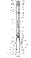
図2は、本発明の実施の形態に係るフロントフォーク21の断面図である。
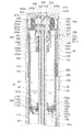
図3は、図2のIII部の拡大図である。
図4は、図2のIV部の拡大図である。
図5は、後述するロッドガイドケース130を下方から見た斜視図である。
本実施の形態に係るフロントフォーク21は、自動二輪車1の車両本体10と前輪2との間に配置されて前輪2を支えるとともに、後述するインナチューブ110が前輪2側にアウタチューブ210が車両本体10側に配置された、所謂倒立型のフロントフォークである。
Next, the front fork 21 will be described in detail.
FIG. 2 is a cross-sectional view of the front fork 21 according to the embodiment of the present invention.
FIG. 3 is an enlarged view of a portion III in FIG.
FIG. 4 is an enlarged view of a portion IV in FIG.
FIG. 5 is a perspective view of a rod guide case 130 described later as viewed from below.
The front fork 21 according to the present embodiment is disposed between the vehicle body 10 and the front wheel 2 of the motorcycle 1 to support the front wheel 2, and an inner tube 110 described later is disposed on the front wheel 2 side and an outer tube 210 is disposed on the vehicle body. This is a so-called inverted front fork disposed on the 10 side.

フロントフォーク21は、インナチューブ110を有して前輪2の車軸に取り付けられる車軸側ユニット100と、アウタチューブ210を有して車両本体10に取り付けられる本体側ユニット200と、を備えている。また、フロントフォーク21は、車軸側ユニット100と本体側ユニット200との間に配置されて、路面の凸凹に伴い前輪2が受ける振動を吸収するコイルスプリング400と、後述する下ばね受け124と協働してコイルスプリング400を支持するスプリング支持部材410と、を備えている。   The front fork 21 includes an axle side unit 100 that has an inner tube 110 and is attached to the axle of the front wheel 2, and a main body side unit 200 that has an outer tube 210 and is attached to the vehicle body 10. The front fork 21 is disposed between the axle side unit 100 and the main body side unit 200, and cooperates with a coil spring 400 that absorbs vibrations received by the front wheels 2 due to unevenness of the road surface, and a lower spring receiver 124 described later. A spring support member 410 that works to support the coil spring 400.

インナチューブ110およびアウタチューブ210は、同軸的に配置された略円筒状の部材であり、この円筒の中心線の方向(軸方向)を、以下では「上下方向」と称し、車両本体10側を上側、前輪2側を下側と称する場合がある。そして、フロントフォーク21は、車軸側ユニット100と本体側ユニット200とが上下方向(軸方向)に相対的に移動することにより、前輪2を支持しながら路面の凸凹を吸収して振動を抑制する。   The inner tube 110 and the outer tube 210 are substantially cylindrical members arranged coaxially, and the direction of the center line (axial direction) of the cylinder is hereinafter referred to as “vertical direction”, and the vehicle body 10 side is referred to as the “center direction”. The upper side and the front wheel 2 side may be referred to as the lower side. The front fork 21 suppresses vibration by absorbing the unevenness of the road surface while supporting the front wheel 2 by relatively moving the axle side unit 100 and the main body side unit 200 in the vertical direction (axial direction). .

[車軸側ユニット100の構成]
車軸側ユニット100は、両端が開口した略円筒状のインナチューブ110と、インナチューブ110における下側の端部(下端部)に取り付けられるとともに前輪2に取り付けられる車軸ブラケット120と、インナチューブ110と車軸ブラケット120との間をシールするオイルシール125と、を備えている。また、車軸側ユニット100は、インナチューブ110における上側の端部(上端部)に取り付けられて、本体側ユニット200の後述するピストンロッド235の移動をガイドするロッドガイドケース130と、ロッドガイドケース130とアウタチューブ210との間をシールするオイルリング135と、ロッドガイドケース130内外のオイルの流通を調整する給排装置150と、を備えている。
[Configuration of Axle Side Unit 100]
The axle unit 100 includes a substantially cylindrical inner tube 110 having both ends opened, an axle bracket 120 attached to the lower end (lower end) of the inner tube 110 and attached to the front wheel 2, And an oil seal 125 that seals between the axle bracket 120. The axle side unit 100 is attached to the upper end (upper end) of the inner tube 110, and guides the movement of a piston rod 235 (described later) of the main unit 200, and the rod guide case 130. An oil ring 135 that seals between the outer tube 210 and the outer tube 210, and a supply / discharge device 150 that adjusts the flow of oil inside and outside the rod guide case 130.

(インナチューブ110の構成)
インナチューブ110は、その外径が、アウタチューブ210の内径よりも小さく形成されており、インナチューブ110がアウタチューブ210内に進入した状態において、インナチューブ110の外周面とアウタチューブ210の内周面との間には環状の油室である環状油室20が形成される。
(Configuration of inner tube 110)
The inner tube 110 has an outer diameter that is smaller than the inner diameter of the outer tube 210. When the inner tube 110 has entered the outer tube 210, the inner tube 110 and the outer tube 210 have an inner periphery. An annular oil chamber 20 which is an annular oil chamber is formed between the surfaces.

インナチューブ110の内周面は、本体側ユニット200の後述するピストン220が滑らかに摺動するように、上下方向に沿って均一な内径で形成されている。ただし、上側の端部の内周面には、ロッドガイドケース130の後述する雄ねじ131aが締め付けられる雌ねじ111が形成されている。他方、インナチューブ110の外周面は、基本的には上下方向に沿って均一な外径で形成されているが、上側の端部には全周に渡って凹んだ凹部112が形成されている。また、インナチューブ110の下側の端部の外周面には、車軸ブラケット120の後述する雌ねじ121aに締め付けられる雄ねじ113が形成されている。また、インナチューブ110には、ロッドガイドケース130が取り付けられた状態において、このロッドガイドケース130よりも下側の部位に、インナチューブ110の内側と環状油室20とを連通する連通孔114が形成されている。   The inner peripheral surface of the inner tube 110 is formed with a uniform inner diameter along the vertical direction so that a piston 220 (described later) of the main body side unit 200 slides smoothly. However, a female screw 111 to which a male screw 131a (described later) of the rod guide case 130 is tightened is formed on the inner peripheral surface of the upper end portion. On the other hand, the outer peripheral surface of the inner tube 110 is basically formed with a uniform outer diameter along the vertical direction, but a concave portion 112 that is recessed over the entire circumference is formed at the upper end. . Further, on the outer peripheral surface of the lower end portion of the inner tube 110, a male screw 113 that is fastened to a female screw 121a (described later) of the axle bracket 120 is formed. In addition, in the state where the rod guide case 130 is attached to the inner tube 110, a communication hole 114 that communicates the inner side of the inner tube 110 and the annular oil chamber 20 is formed at a lower portion than the rod guide case 130. Is formed.

上述した凹部112には、アウタチューブ210の内周面との摺動を円滑にするためのスライドブッシュ115が嵌め込まれている。スライドブッシュ115は、円筒状に形成された軸受であり、インナチューブ110に取り付けられた状態で、その外周面がインナチューブ110の外周面よりも外側に突出するように、スライドブッシュ115の外径がインナチューブ110の外径よりも大きく設定されている。
そして、このインナチューブ110内には所定量のオイルが注入されている。
A slide bush 115 for smooth sliding with the inner peripheral surface of the outer tube 210 is fitted into the recess 112 described above. The slide bush 115 is a cylindrical bearing, and is attached to the inner tube 110 so that the outer peripheral surface of the slide bush 115 protrudes outward from the outer peripheral surface of the inner tube 110. Is set larger than the outer diameter of the inner tube 110.
A predetermined amount of oil is injected into the inner tube 110.

(車軸ブラケット120の構成)
車軸ブラケット120には、図2に示すように、インナチューブ110が挿入される凹部121と、前輪2の車軸を取り付け可能な車軸取付孔122と、が形成されている。凹部121には、インナチューブ110の雄ねじ113が締め付けられる雌ねじ121aと、インナチューブ110の外周面と凹部121との間をシールするオイルシール125が嵌め込まれるシール溝121bが形成されている。また、凹部121には、コイルスプリング400の下側の端部が載り、スプリング荷重を受ける下ばね受け124が取り付けられている。
(Configuration of axle bracket 120)
As shown in FIG. 2, the axle bracket 120 is formed with a recess 121 into which the inner tube 110 is inserted, and an axle attachment hole 122 to which the axle of the front wheel 2 can be attached. The recess 121 is formed with a female screw 121a to which the male screw 113 of the inner tube 110 is fastened, and a seal groove 121b into which an oil seal 125 for sealing between the outer peripheral surface of the inner tube 110 and the recess 121 is fitted. The lower end of the coil spring 400 rests on the recess 121, and a lower spring receiver 124 that receives a spring load is attached to the recess 121.

車軸ブラケット120は、インナチューブ110の雄ねじ113が雌ねじ121aに締め付けられることで、インナチューブ110における下側の端部の開口を塞ぐように取り付けられる。そして、凹部121のシール溝121bに嵌め込まれたオイルシール125が、インナチューブ110の外周面と車軸ブラケット120との間をシールすることでインナチューブ110内に注入されたオイルの漏れを防止する。   The axle bracket 120 is attached so as to close the opening of the lower end portion of the inner tube 110 by fastening the male screw 113 of the inner tube 110 to the female screw 121a. The oil seal 125 fitted in the seal groove 121b of the recess 121 seals between the outer peripheral surface of the inner tube 110 and the axle bracket 120, thereby preventing leakage of oil injected into the inner tube 110.

(ロッドガイドケース130の構成)
ロッドガイドケース130は、図3及び図5に示すように、中心線の方向が上下方向となるように形成された円筒状の円筒状部131と、この円筒状部131における下側の端部の下方に設けられて下側の端部の開口を塞ぐように半径方向の内側に向かうように形成された内向部132と、円筒状部131における上側の端部の上方において、半径方向の外側に向かうように形成された外向部133と、を備えている。
(Configuration of rod guide case 130)
As shown in FIGS. 3 and 5, the rod guide case 130 includes a cylindrical cylindrical portion 131 formed such that the direction of the center line is the vertical direction, and a lower end portion of the cylindrical portion 131. An inward portion 132 that is formed so as to be directed inward in the radial direction so as to close the opening of the lower end portion, and on the outer side in the radial direction above the upper end portion of the cylindrical portion 131. And an outward portion 133 that is formed so as to face toward the center.

円筒状部131における上側の端部の外周面には、インナチューブ110に形成された雌ねじ111に締め付けられる雄ねじ131aが形成されている。そして、雄ねじ131aの下方における円筒状部131は、その外径が、インナチューブ110の内径よりも小さく形成されており、ロッドガイドケース130がインナチューブ110に取り付けられた状態において、円筒状部131の外周面とインナチューブ110の内周面との間には環状の隙間である環状隙間25(図7も参照)が形成される。また、円筒状部131における下側の端部には、内外を連通する連通孔131cが形成されている。また、円筒状部131における上側の端部の外周面には、内側に凹んだ円筒状部側凹部131dが、上下方向に関しては雄ねじ131aの上方から下方にかけて、周方向に関しては後述する外向部側凹部133cと対応する位置に形成されている。   A male screw 131 a that is fastened to a female screw 111 formed on the inner tube 110 is formed on the outer peripheral surface of the upper end portion of the cylindrical portion 131. The cylindrical portion 131 below the male screw 131 a has an outer diameter smaller than the inner diameter of the inner tube 110, and the cylindrical portion 131 is in a state where the rod guide case 130 is attached to the inner tube 110. An annular gap 25 (see also FIG. 7), which is an annular gap, is formed between the outer peripheral surface of the inner tube 110 and the inner peripheral surface of the inner tube 110. In addition, a communication hole 131 c that communicates the inside and the outside is formed at the lower end of the cylindrical portion 131. In addition, on the outer peripheral surface of the upper end portion of the cylindrical portion 131, a cylindrical portion-side concave portion 131d that is recessed inwardly extends from the upper side to the lower side of the male screw 131a in the vertical direction, and the outward portion side that will be described later in the circumferential direction. It is formed at a position corresponding to the recess 133c.

内向部132の中央部には、上下方向に貫通する貫通孔を利用して形成されたバルブ室140が形成されている。バルブ室140には、給排装置150が配置される。また、内向部132の外周面には、インナチューブ110の内周面との間をシールするオイルシール145が嵌め込まれるシール溝132bが形成されている。
バルブ室140は、内向部132を貫通する貫通孔132aと内向部132における下側の端面から凹んだ第1凹部141および第2凹部142にて構成される。第1凹部141および第2凹部142は、下側の端面から上側の端面にかけて径が小さくなるように異なる円柱状の凹みであり、径が大きい円柱状の第1凹部141と、径が小さい円柱状の第2凹部142と、から構成される。また、第1凹部141の内周面には、この内周面から外側に凹んだ溝141aが全周に渡って形成されている。
A valve chamber 140 formed using a through hole penetrating in the vertical direction is formed at the center of the inward portion 132. A supply / discharge device 150 is disposed in the valve chamber 140. Further, a seal groove 132 b into which an oil seal 145 that seals between the inner peripheral surface of the inner tube 110 is fitted is formed on the outer peripheral surface of the inward portion 132.
The valve chamber 140 includes a through hole 132 a that penetrates the inward portion 132 and a first concave portion 141 and a second concave portion 142 that are recessed from the lower end surface of the inward portion 132. The first concave portion 141 and the second concave portion 142 are different cylindrical recesses so that the diameter decreases from the lower end surface to the upper end surface, and the cylindrical first recess 141 having a large diameter and a circle having a small diameter. And a columnar second recess 142. In addition, a groove 141a that is recessed outward from the inner peripheral surface is formed on the inner peripheral surface of the first recess 141 over the entire periphery.

外向部133の外周面には、アウタチューブ210の内周面とロッドガイドケース130との間をシールするオイルリング135が嵌め込まれるリング溝133aが周方向の全域に渡って形成されている。リング溝133aに嵌め込まれたオイルリング135が、上述した環状油室20における上側の部位を区画する部材として機能する。
外向部133における下側の端面133bは、インナチューブ110における上側の端面が突き当たる突当面として機能する。つまり、外向部133の下側の端面133bは、上下方向に直交する面に形成され、インナチューブ110の上側の端面と全周に渡って接触し、インナチューブ110の内部空間を封止する。そして、外向部133には、下側の端面133bから上側に凹んだ外向部側凹部133cが、周方向の一部の領域であって、円筒状部131の円筒状部側凹部131dと対応する位置に形成されている。つまり、図3及び図5に示すように、外向部側凹部133cと円筒状部側凹部131dとは、連続するように形成されており、環状油室20と環状隙間25とを連通する通路である連通路40として機能する。
On the outer peripheral surface of the outward portion 133, a ring groove 133a into which an oil ring 135 that seals between the inner peripheral surface of the outer tube 210 and the rod guide case 130 is fitted is formed over the entire region in the circumferential direction. The oil ring 135 fitted in the ring groove 133a functions as a member that divides the upper portion of the annular oil chamber 20 described above.
The lower end surface 133b of the outward portion 133 functions as a contact surface against which the upper end surface of the inner tube 110 abuts. That is, the lower end surface 133b of the outward portion 133 is formed on a surface orthogonal to the vertical direction, contacts the upper end surface of the inner tube 110 over the entire circumference, and seals the inner space of the inner tube 110. In the outward portion 133, an outward portion side recess 133 c that is recessed upward from the lower end surface 133 b is a partial region in the circumferential direction, and corresponds to the cylindrical portion side recess 131 d of the cylindrical portion 131. Formed in position. That is, as shown in FIGS. 3 and 5, the outward-portion-side concave portion 133 c and the cylindrical-portion-side concave portion 131 d are formed so as to be continuous, and are passages that communicate the annular oil chamber 20 and the annular gap 25. It functions as a certain communication path 40.

以上のように構成されたロッドガイドケース130においては、内向部132が、インナチューブ110内の空間を、内向部132よりも上方の空間と内向部132よりも下方の空間とに区画する。また、円筒状部131が、内向部132よりも上方の空間を、円筒状部131の内側の空間と円筒状部131の外側の空間とに区画する。そして、内向部132よりも上方であって円筒状部131の内側の部位が、オイルが溜まる油溜室45として機能する。また、内向部132よりも下方であってインナチューブ110の内側の空間が、主となる減衰力を発生するオイルが溜まる作動油室50として機能する。また、内向部132よりも上方であって円筒状部131の外側の部位が、上述した環状隙間25である。内向部132に形成されたシール溝132bに嵌め込まれたオイルシール145が、環状隙間25と作動油室50とを区画する。   In the rod guide case 130 configured as described above, the inward portion 132 divides the space in the inner tube 110 into a space above the inward portion 132 and a space below the inward portion 132. The cylindrical portion 131 divides the space above the inward portion 132 into a space inside the cylindrical portion 131 and a space outside the cylindrical portion 131. A portion above the inward portion 132 and inside the cylindrical portion 131 functions as an oil reservoir chamber 45 in which oil is accumulated. Further, a space below the inward portion 132 and inside the inner tube 110 functions as a hydraulic oil chamber 50 in which oil that generates a main damping force is accumulated. Further, the above-described annular gap 25 is located above the inward portion 132 and outside the cylindrical portion 131. An oil seal 145 fitted in a seal groove 132 b formed in the inward portion 132 defines the annular gap 25 and the hydraulic oil chamber 50.

付言すれば、オイルリング135およびオイルシール145を保持するロッドガイドケース130は、インナチューブ110における上側の端部に取り付けられてアウタチューブ210の内周面とインナチューブ110の外周面との間に形成された環状油室20の上側の端部を区画すると共に、インナチューブ110の内側の部位に椀状に形成された椀部の一例としての円筒状部131及び内向部132を有し、インナチューブ110内の空間を、円筒状部131及び内向部132よりも上方の空間である上方空間の一例としての油溜室45と下方の空間である下方空間の一例としての作動油室50及び環状隙間25とに区分する隔壁部材として機能する。そして、オイルリング135およびオイルシール145を保持するロッドガイドケース130は、下方空間の一例としての作動油室50及び環状隙間25を、ロッドガイドケース130とインナチューブ110との間の間隙空間の一例としての環状隙間25と、環状隙間25以外の空間の一例としての作動油室50とに区分すると共に、オイルが存在する油溜室45と環状隙間25とを連通するように連通孔131cが形成され、環状油室20の上部と環状隙間25とを連通する連通路40が設けられている。
なお、インナチューブ110内における油溜室45の上部の空間及びアウタチューブ210内の上部の空間とは繋がり、これらの空間に空気が充填されている。ゆえに、油溜室45の下部は、インナチューブ110内に注入されたオイルが溜まるオイル室46として機能し、油溜室45の上部の空間及びアウタチューブ210内の上部の空間は空気室47として機能する。
In other words, the rod guide case 130 that holds the oil ring 135 and the oil seal 145 is attached to an upper end portion of the inner tube 110 and is interposed between the inner peripheral surface of the outer tube 210 and the outer peripheral surface of the inner tube 110. The upper end portion of the formed annular oil chamber 20 is partitioned, and a cylindrical portion 131 and an inward portion 132 as an example of a hook portion formed in a hook shape at a portion inside the inner tube 110 are provided. The space in the tube 110 is divided into an oil reservoir chamber 45 as an example of an upper space that is a space above the cylindrical portion 131 and the inward portion 132, and a hydraulic oil chamber 50 and an annular shape as an example of a lower space that is a lower space. It functions as a partition member that is divided into gaps 25. Then, the rod guide case 130 holding the oil ring 135 and the oil seal 145 has an operating oil chamber 50 and an annular gap 25 as an example of a lower space, and an example of a gap space between the rod guide case 130 and the inner tube 110. And a hydraulic oil chamber 50 as an example of a space other than the annular gap 25, and a communication hole 131c is formed so that the oil reservoir chamber 45 in which oil exists and the annular gap 25 communicate with each other. In addition, a communication path 40 that communicates the upper portion of the annular oil chamber 20 and the annular gap 25 is provided.
The space above the oil reservoir 45 in the inner tube 110 and the space above the outer tube 210 are connected to each other, and these spaces are filled with air. Therefore, the lower part of the oil reservoir 45 functions as an oil chamber 46 in which the oil injected into the inner tube 110 is accumulated, and the upper space of the oil reservoir 45 and the upper space in the outer tube 210 serve as the air chamber 47. Function.

(給排装置150の構成)
給排装置150は、図3に示すように、油溜室45から作動油室50へのオイルの流れを許容するとともに、作動油室50から油溜室45へのオイルの流れを阻止するチェック弁151と、チェック弁151の下方に配置されたバックアップスプリング152と、バックアップスプリング152の下方に配置されてバックアップスプリング152が着座するスプリングシート153と、これらチェック弁151、バックアップスプリング152およびスプリングシート153の下方への脱落を抑制するストッパリング154と、を備える。
(Configuration of supply / discharge device 150)
As shown in FIG. 3, the supply / discharge device 150 allows the flow of oil from the oil reservoir chamber 45 to the hydraulic oil chamber 50 and also checks the flow of oil from the hydraulic oil chamber 50 to the oil reservoir 45. A valve 151, a backup spring 152 disposed below the check valve 151, a spring seat 153 disposed below the backup spring 152 on which the backup spring 152 is seated, the check valve 151, the backup spring 152, and the spring seat 153. And a stopper ring 154 that suppresses the downward drop.

チェック弁151は、下側の端部にフランジ151aが形成された円筒状の部材である。そして、このチェック弁151の内周には、ピストンロッド235を摺動可能に支持する円筒状のブッシュ151bが圧入されている。そして、チェック弁151は、フランジ151aがバルブ室140の第2凹部142に配置されるとともに、フランジ151aにおける上側の端面が、第2凹部142の底部(上側の端面)に接触する状態と離間した状態とに遷移するように、ピストンロッド235の外周に沿って上下方向に移動する。   The check valve 151 is a cylindrical member in which a flange 151a is formed at the lower end. A cylindrical bush 151b that slidably supports the piston rod 235 is press-fitted into the inner periphery of the check valve 151. In the check valve 151, the flange 151a is disposed in the second recess 142 of the valve chamber 140, and the upper end surface of the flange 151a is separated from the state in contact with the bottom (upper end surface) of the second recess 142. It moves up and down along the outer periphery of the piston rod 235 so as to transition to the state.

バックアップスプリング152は、例えば皿ばね状の部材であり、スプリングシート153に着座した状態において、内周部又は外周部において周方向の複数箇所が、チェック弁151のフランジ151aにおける下側の端面に接触する。   The backup spring 152 is, for example, a disc spring-like member, and in a state where the backup spring 152 is seated on the spring seat 153, a plurality of locations in the circumferential direction at the inner peripheral portion or the outer peripheral portion contact the lower end surface of the flange 151a of the check valve 151. To do.

スプリングシート153は、中央部に孔が形成された円板状の部材であり、外周部に半径方向に凹凸する凹部と凸部が周方向に交互に形成されている。そして、スプリングシート153は、バルブ室140の第1凹部141に配置されて、外周部に形成された凹部を介してオイルを流通させる。   The spring seat 153 is a disk-shaped member having a hole formed in the center, and concave and convex portions that are uneven in the radial direction are alternately formed in the circumferential direction on the outer peripheral portion. And the spring seat 153 is arrange | positioned at the 1st recessed part 141 of the valve chamber 140, and distribute | circulates oil through the recessed part formed in the outer peripheral part.

ストッパリング154は、C字状の止め輪であり、バルブ室140の第1凹部141の内周面に形成された溝141aに嵌め込まれる。そして、ストッパリング154は、スプリングシート153の下方に配置されて、スプリングシート153を下側から支持する。   The stopper ring 154 is a C-shaped retaining ring and is fitted into a groove 141 a formed on the inner peripheral surface of the first recess 141 of the valve chamber 140. The stopper ring 154 is disposed below the spring seat 153 and supports the spring seat 153 from below.

[本体側ユニット200の構成]
本体側ユニット200は、図2に示すように、両端が開口した略円筒状のアウタチューブ210と、アウタチューブ210における下側の端部(下端部)に取り付けられたガイドブッシュ211と、ガイドブッシュ211よりも下方に取り付けられたオイルシール212と、オイルシール212よりも下方に取り付けられたダストシール213と、を備えている。
[Configuration of main unit 200]
As shown in FIG. 2, the main unit 200 includes a substantially cylindrical outer tube 210 having both ends opened, a guide bush 211 attached to a lower end (lower end) of the outer tube 210, and a guide bush. An oil seal 212 attached below 211 and a dust seal 213 attached below oil seal 212 are provided.

また、本体側ユニット200は、インナチューブ110の内側の空間に形成された作動油室50内を摺動するピストン220と、ピストン220を保持するピストンボルト230と、ピストンボルト230を下側の端部に保持するピストンロッド235と、を備えている。   Further, the main unit 200 has a piston 220 that slides in a hydraulic oil chamber 50 formed in a space inside the inner tube 110, a piston bolt 230 that holds the piston 220, and a piston bolt 230 that is positioned at the lower end. A piston rod 235 that is held by the portion.

また、本体側ユニット200は、アウタチューブ210における上側の端部(上端部)に取り付けられて上側の開口部を塞ぐキャップ240と、このキャップ240に取り付けられるとともにピストンロッド235における上側の端部を支持する支持部材250と、を備えている。また、本体側ユニット200は、キャップ240の後述する円筒状部241の内周と支持部材250の第1円筒状部251の外周とで形成される環状の凹部に配置された円筒状のストッパラバー255と、ストッパラバー255の下方に配置された円板状のストッパ板256と、ストッパ板256の下方に配置されたストッパリング257と、を備えている。   Further, the main unit 200 is attached to the upper end (upper end) of the outer tube 210 and closes the upper opening, and the upper end of the piston rod 235 is attached to the cap 240. And a supporting member 250 for supporting. The main unit 200 is a cylindrical stopper rubber disposed in an annular recess formed by an inner periphery of a cylindrical portion 241 (to be described later) of the cap 240 and an outer periphery of a first cylindrical portion 251 of the support member 250. 255, a disk-shaped stopper plate 256 disposed below the stopper rubber 255, and a stopper ring 257 disposed below the stopper plate 256.

また、本体側ユニット200は、オイルの粘性抵抗を利用した減衰力を発生する減衰力発生装置260と、減衰力発生装置260の減衰力を調整する減衰力調整装置270とを備えている。また、本体側ユニット200は、下ばね受け124と協働してコイルスプリング400を支持するスプリング支持部材410を備えている。   The main unit 200 includes a damping force generator 260 that generates a damping force using the viscous resistance of oil, and a damping force adjuster 270 that adjusts the damping force of the damping force generator 260. The main unit 200 includes a spring support member 410 that supports the coil spring 400 in cooperation with the lower spring receiver 124.

(アウタチューブ210の構成)
アウタチューブ210は、図2に示すように、略円筒状の部材であるが、下側の端部は、ガイドブッシュ211、オイルシール212およびダストシール213を内側に保持可能なように拡径されており、上側の端部の内周面には、キャップ240に形成された雄ねじ241aが締め付けられる雌ねじ210aが形成されている。
(Configuration of outer tube 210)
As shown in FIG. 2, the outer tube 210 is a substantially cylindrical member, but its lower end is enlarged so that the guide bush 211, the oil seal 212, and the dust seal 213 can be held inside. On the inner peripheral surface of the upper end portion, a female screw 210a to which a male screw 241a formed on the cap 240 is fastened is formed.

ガイドブッシュ211は、アウタチューブ210の内周面とインナチューブ110の外周面との摺動を円滑にするための部材である。このガイドブッシュ211は、円筒状に形成された軸受であり、アウタチューブ210に取り付けられた状態で、その内周面がアウタチューブ210の内周面よりも内側に突出するように、ガイドブッシュ211の内径がアウタチューブ210の内径よりも小さく設定されている。そして、このガイドブッシュ211が、上述した環状油室20における下側の部位を区画する部材として機能する。   The guide bush 211 is a member for smoothly sliding the inner peripheral surface of the outer tube 210 and the outer peripheral surface of the inner tube 110. The guide bush 211 is a bearing formed in a cylindrical shape, and is attached to the outer tube 210 so that its inner peripheral surface protrudes inward from the inner peripheral surface of the outer tube 210. Is set to be smaller than the inner diameter of the outer tube 210. And this guide bush 211 functions as a member which divides the lower site | part in the annular oil chamber 20 mentioned above.

オイルシール212は、アウタチューブ210とインナチューブ110との摺動に伴い、ガイドブッシュ211から漏れる作動油の外部への流出を防止する。
ダストシール213は、このフロントフォーク21の外部からの水分や挨等の異物の浸入を抑制する。
The oil seal 212 prevents the hydraulic oil leaking from the guide bush 211 from flowing out to the outside as the outer tube 210 and the inner tube 110 slide.
The dust seal 213 suppresses entry of foreign matter such as moisture and dust from the outside of the front fork 21.

(ピストン220の構成)
ピストン220は、図4に示すように、上下方向に形成された複数の油路を有する円筒状の部材である。より具体的には、ピストン220には、ピストンボルト230の後述する第3円筒状部233を通すために中央部に上下方向に貫通されたボルト孔220aと、ボルト孔220aよりも半径方向の外側の部位に上下方向に貫通された孔にて構成される第1油路220bと、第1油路220bよりも半径方向の外側の部位に上下方向に貫通された孔にて構成される第2油路220cとが形成されている。また、ピストン220の外周面には、インナチューブ110の内周面との間をシールするオイルリング221が嵌め込まれるリング溝220dが周方向の全域に渡って形成されている。このリング溝220dに嵌め込まれたオイルリング221が、作動油室50を、オイルリング221よりも上側に位置してピストンロッド235が存在する油室である上方位置空間の一例としてのピストンロッド側油室51と、オイルリング221よりも下側に位置する油室である下方位置空間の一例としてのピストン側油室52とに区画する。つまり、オイルリング221を保持したピストン220が、作動油室50を、ピストンロッド側油室51とピストン側油室52とに区画する。そして、上述した第1油路220bおよび第2油路220cは、ピストンロッド側油室51とピストン側油室52とを連通する連通路として機能する。そして、このピストン220は、減衰力発生装置260の一部を構成する。この減衰力発生装置260については後で詳述する。
(Configuration of piston 220)
As shown in FIG. 4, the piston 220 is a cylindrical member having a plurality of oil passages formed in the vertical direction. More specifically, the piston 220 is provided with a bolt hole 220a vertically penetrated in the center part for passing a third cylindrical part 233, which will be described later, of the piston bolt 230, and a radially outer side than the bolt hole 220a. A first oil passage 220b constituted by a hole penetrating in the vertical direction in the portion of the second and a second oil passage constituted by a hole penetrating in the vertical direction in a portion radially outside the first oil passage 220b. An oil passage 220c is formed. Further, a ring groove 220d into which an oil ring 221 that seals between the inner peripheral surface of the inner tube 110 is fitted is formed on the outer peripheral surface of the piston 220 over the entire region in the circumferential direction. A piston rod side oil as an example of an upper position space in which the oil ring 221 fitted in the ring groove 220d is an oil chamber in which the hydraulic oil chamber 50 is located above the oil ring 221 and the piston rod 235 exists. The chamber 51 is divided into a piston-side oil chamber 52 as an example of a lower position space that is an oil chamber located below the oil ring 221. That is, the piston 220 holding the oil ring 221 partitions the hydraulic oil chamber 50 into the piston rod side oil chamber 51 and the piston side oil chamber 52. The first oil passage 220b and the second oil passage 220c described above function as a communication passage that connects the piston rod-side oil chamber 51 and the piston-side oil chamber 52. The piston 220 constitutes a part of the damping force generator 260. The damping force generator 260 will be described in detail later.

(ピストンボルト230の構成)
ピストンボルト230は、図4に示すように、円筒状の第1円筒状部231と、第1円筒状部231の下側の端部から下方に延びるように形成された円筒状の第2円筒状部232と、第2円筒状部232の下側の端部から下方に延びるように形成された円筒状の第3円筒状部233と、を有している。第1円筒状部231の内周面には、ピストンロッド235に形成された後述する雄ねじ235bが締め付けられる雌ねじ231aが形成されている。また、第3円筒状部233における下側の端部には、雄ねじ233aが形成されている。また、第2円筒状部232には、内外を連通する半径方向(上下方向に直交する方向)の貫通孔22aが形成されている。この貫通孔22aおよび第3円筒状部233の内側の部位が、ピストン220に形成された第1油路220b及び第2油路220cを迂回してピストンロッド側油室51とピストン側油室52とを連通する迂回路60として機能する。
(Configuration of piston bolt 230)
As shown in FIG. 4, the piston bolt 230 includes a cylindrical first cylindrical portion 231 and a cylindrical second cylinder formed so as to extend downward from the lower end portion of the first cylindrical portion 231. And a cylindrical third cylindrical portion 233 formed so as to extend downward from the lower end portion of the second cylindrical portion 232. On the inner peripheral surface of the first cylindrical portion 231, a female screw 231 a to which a male screw 235 b described later formed on the piston rod 235 is tightened is formed. A male screw 233a is formed at the lower end of the third cylindrical portion 233. Further, the second cylindrical portion 232 is formed with a through hole 2 3 2a in the radial direction (a direction perpendicular to the vertical direction) communicating between the inside and the outside. Inner portion of the through hole 2 3 2a and a third cylindrical portion 233, a first oil passage 220b and the second oil passage 220c to bypass the piston rod side oil chamber 51 and the piston side oil formed on the piston 220 It functions as a bypass 60 that communicates with the chamber 52.

(ピストンロッド235の構成)
ピストンロッド235は、円筒状の部材であり、上側の端部の外周面には、図3に示すように、支持部材250に形成された後述する雌ねじ252aに締め付けられる雄ねじ235aが形成されており、下側の端部の外周面には、図4に示すように、ピストンボルト230に形成された雌ねじ231aに締め付けられる雄ねじ235bが形成されている。また、ピストンロッド235における雄ねじ235bよりも上方の部位には、内外を連通する半径方向の貫通孔235cが形成されている。貫通孔235cは、上下方向に直交する方向から見ると上下方向が長い長孔状に形成されている。また、貫通孔235cは、ピストンロッド235の外周面に、周方向に180度間隔で形成されている。
なお、ピストンロッド235の外周面をなす外径をDoとした場合の面積πDo/4を、以下では「ピストンロッド235の断面積」と称す。そして、本実施の形態に係るピストンロッド235の断面積は、環状油室20の断面積(上下方向に直交する面で切断した断面積)よりも小さく設定されている。
(Configuration of piston rod 235)
The piston rod 235 is a cylindrical member. On the outer peripheral surface of the upper end portion, as shown in FIG. 3, a male screw 235a that is tightened to a female screw 252a (described later) formed on the support member 250 is formed. On the outer peripheral surface of the lower end portion, as shown in FIG. 4, a male screw 235b to be fastened to a female screw 231a formed on the piston bolt 230 is formed. Further, a radial through hole 235c that communicates the inside and the outside is formed in a portion of the piston rod 235 above the male screw 235b. The through hole 235c is formed in a long hole shape with a long vertical direction when viewed from a direction orthogonal to the vertical direction. The through holes 235c are formed on the outer peripheral surface of the piston rod 235 at intervals of 180 degrees in the circumferential direction.
Incidentally, the area πDo 2/4 in the case of a major diameter comprising an outer circumferential surface of the piston rod 235 was Do, hereinafter referred to as "cross-sectional area of the piston rod 235 '. And the cross-sectional area of the piston rod 235 which concerns on this Embodiment is set smaller than the cross-sectional area of the annular oil chamber 20 (cross-sectional area cut | disconnected by the surface orthogonal to an up-down direction).

(キャップ240の構成)
キャップ240は、図3に示すように、円筒状の円筒状部241と、この円筒状部241における上側の端部に設けられて開口を塞ぐように半径方向の内側に向かうように形成された内向部242と、内向部242の中央部における下側の端面から下方に突出する円柱状の円柱状部243と、を有している。
(Configuration of cap 240)
As shown in FIG. 3, the cap 240 is formed at a cylindrical portion 241 having a cylindrical shape and toward the inner side in the radial direction so as to close the opening provided at an upper end portion of the cylindrical portion 241. It has an inward portion 242 and a cylindrical columnar portion 243 that protrudes downward from the lower end face in the central portion of the inward portion 242.

円筒状部241の外周面には、アウタチューブ210の内周面に形成された雌ねじ210aに締め付けられる雄ねじ241aと、雄ねじ241aの上方においてアウタチューブ210の内周面との間をシールするシール部材245が嵌め込まれるシール溝241bが形成されている。また、円筒状部241の外周面におけるシール溝241bの上方には、この外周面から半径方向の外側に突出する突出部241cが設けられている。   On the outer peripheral surface of the cylindrical portion 241, a seal member that seals between a male screw 241 a fastened to a female screw 210 a formed on the inner peripheral surface of the outer tube 210 and an inner peripheral surface of the outer tube 210 above the male screw 241 a. A seal groove 241b into which 245 is fitted is formed. In addition, a protruding portion 241c that protrudes outward in the radial direction from the outer peripheral surface is provided above the seal groove 241b on the outer peripheral surface of the cylindrical portion 241.

円柱状部243の外周面には、支持部材250に形成された雌ねじ251aに締め付けられる雄ねじ243aが形成されている。そして、内向部242および円柱状部243には、上下方向に貫通し、後述する第1アジャストボルト312、第2アジャストボルト322それぞれが嵌め込まれる貫通孔243b、243cが形成されている。   A male screw 243 a that is fastened to a female screw 251 a formed on the support member 250 is formed on the outer peripheral surface of the cylindrical portion 243. The inward portion 242 and the columnar portion 243 are formed with through holes 243b and 243c that penetrate in the vertical direction and into which a first adjustment bolt 312 and a second adjustment bolt 322, which will be described later, are fitted, respectively.

キャップ240は、円筒状部241の外周面に形成された雄ねじ241aがアウタチューブ210の内周面に形成された雌ねじ210aに締め付けられることでアウタチューブ210に取り付けられる。そして、円筒状部241に形成されたシール溝241bに嵌め込まれたシール部材245が、アウタチューブ210内を密封する。   The cap 240 is attached to the outer tube 210 by fastening a male screw 241 a formed on the outer peripheral surface of the cylindrical portion 241 to a female screw 210 a formed on the inner peripheral surface of the outer tube 210. The seal member 245 fitted in the seal groove 241b formed in the cylindrical portion 241 seals the inside of the outer tube 210.

(支持部材250の構成)
支持部材250は、図3に示すように、薄肉円筒状の第1円筒状部251と、第1円筒状部251の下方において第1円筒状部251の肉厚よりも厚肉で円筒状に形成された第2円筒状部252と、を有している。第1円筒状部251の内周面には、キャップ240に形成された雄ねじ243aが締め付けられる雌ねじ251aが形成されている。第1円筒状部251の外周面には、ストッパリング257が嵌められるリング溝251bが形成されている。また、第2円筒状部252の内周面には、ピストンロッド235に形成された雄ねじ235aが締め付けられる雌ねじ252aが形成されている。
(Configuration of support member 250)
As shown in FIG. 3, the support member 250 has a thin cylindrical first cylindrical portion 251 and a cylindrical shape that is thicker than the thickness of the first cylindrical portion 251 below the first cylindrical portion 251. A second cylindrical portion 252 formed. On the inner peripheral surface of the first cylindrical portion 251, a female screw 251a to which a male screw 243a formed on the cap 240 is fastened is formed. A ring groove 251 b in which the stopper ring 257 is fitted is formed on the outer peripheral surface of the first cylindrical portion 251. A female screw 252a to which a male screw 235a formed on the piston rod 235 is fastened is formed on the inner peripheral surface of the second cylindrical portion 252.

そして、支持部材250は、第1円筒状部251の雌ねじ251aとキャップ240の雄ねじ243aとが締め付けられることでキャップ240に保持されるとともに、第2円筒状部252の雌ねじ252aにピストンロッド235に形成された雄ねじ235aが締め付けられることでピストンロッド235を保持する。ピストンロッド235は、さらに、ロックナット254を、支持部材250に向けて締め付けることで支持部材250に固定され、ひいてはキャップ240に固定される。   The support member 250 is held by the cap 240 by tightening the female screw 251a of the first cylindrical portion 251 and the male screw 243a of the cap 240, and is attached to the piston rod 235 on the female screw 252a of the second cylindrical portion 252. The formed male screw 235a is tightened to hold the piston rod 235. Further, the piston rod 235 is fixed to the support member 250 by tightening the lock nut 254 toward the support member 250, and thus fixed to the cap 240.

支持部材250の第1円筒状部251の雌ねじ251aにキャップ240の雄ねじ243aを締め付ける際には、第1円筒状部251の上側の端面が、キャップ240の内向部242の下側の端面に突き当たるまで締め付けられる。ゆえに、キャップ240の内向部242の下側の端面は、支持部材250の上側の端面が突き当たる突当面として機能する。   When the male screw 243 a of the cap 240 is fastened to the female screw 251 a of the first cylindrical portion 251 of the support member 250, the upper end surface of the first cylindrical portion 251 abuts on the lower end surface of the inward portion 242 of the cap 240. Until tightened. Therefore, the lower end surface of the inward portion 242 of the cap 240 functions as an abutment surface against which the upper end surface of the support member 250 abuts.

(ストッパラバー255などの構成)
図3に示すように、ストッパラバー255は、ゴムなどの弾性部材で成形された円筒状の部材であり、キャップ240の円筒状部241の内周と支持部材250の第1円筒状部251の外周とで形成される環状の凹部に配置される。
ストッパ板256は、中央部に支持部材250の第1円筒状部251を通す孔が形成された円板状の部材である。
ストッパリング257は、C字状の止め輪であり、支持部材250の第1円筒状部251に形成されたリング溝251bに嵌められる。そして、ストッパリング257が、ストッパラバー255およびストッパ板256の下方への脱落を抑制する。
(Configuration of stopper rubber 255)
As shown in FIG. 3, the stopper rubber 255 is a cylindrical member formed of an elastic member such as rubber, and the inner periphery of the cylindrical portion 241 of the cap 240 and the first cylindrical portion 251 of the support member 250. It arrange | positions at the cyclic | annular recessed part formed with an outer periphery.
The stopper plate 256 is a disk-shaped member in which a hole through which the first cylindrical portion 251 of the support member 250 passes is formed in the center portion.
The stopper ring 257 is a C-shaped retaining ring and is fitted into a ring groove 251 b formed in the first cylindrical portion 251 of the support member 250. Then, the stopper ring 257 suppresses the stopper rubber 255 and the stopper plate 256 from dropping downward.

そして、フロントフォーク21の圧縮時に、車軸側ユニット100の上側の端部がストッパ板256に突き当たるとともに、ストッパ板256がキャップ240の円筒状部241の下側の端面に突き当たることで、車軸側ユニット100の上方への移動が規制される。このとき、ストッパラバー255が弾性変形することで、ストッパ板256がキャップ240の円筒状部241の下側の端面に突き当たる際の衝撃が緩和される。   When the front fork 21 is compressed, the upper end of the axle-side unit 100 abuts against the stopper plate 256, and the stopper plate 256 abuts against the lower end surface of the cylindrical portion 241 of the cap 240. The upward movement of 100 is restricted. At this time, the stopper rubber 255 is elastically deformed, so that the impact when the stopper plate 256 hits the lower end surface of the cylindrical portion 241 of the cap 240 is alleviated.

(減衰力発生装置260の構成)
減衰力発生装置260は、図4に示すように、上述したピストン220と、ピストン220の下方に配置されてピストン220に形成された第1油路220bにおける下側の端部を塞ぐ第1バルブ261と、ピストン220の上方に配置されてピストン220に形成された第2油路220cにおける上側の端部を塞ぐ第2バルブ262と、第1バルブ261の下方に配置された第1ワッシャ263と、第2バルブ262の上方に配置された第2ワッシャ264と、を備えている。
(Configuration of damping force generator 260)
As shown in FIG. 4, the damping force generator 260 is a first valve that closes the lower end of the above-described piston 220 and the first oil passage 220 b that is disposed below the piston 220 and formed in the piston 220. 261, a second valve 262 disposed above the piston 220 and closing the upper end of the second oil passage 220c formed in the piston 220, and a first washer 263 disposed below the first valve 261. , And a second washer 264 disposed above the second valve 262.

そして、図4に示すように、これらピストン220、第1バルブ261、第2バルブ262、第1ワッシャ263および第2ワッシャ264は、ロックナット265が、ピストンボルト230の第3円筒状部233に形成された雄ねじ233aに締め付けられることで、スプリング支持部材410などと共に、ロックナット265と、ピストンボルト230の第2円筒状部232の下側の端面との間に取り付けられる。   As shown in FIG. 4, the piston 220, the first valve 261, the second valve 262, the first washer 263, and the second washer 264 have a lock nut 265 on the third cylindrical portion 233 of the piston bolt 230. By being fastened to the formed male screw 233 a, the spring support member 410 and the like are attached between the lock nut 265 and the lower end surface of the second cylindrical portion 232 of the piston bolt 230.

(減衰力調整装置270の構成)
減衰力調整装置270は、ピストンボルト230に形成された迂回路60を介してピストンロッド側油室51とピストン側油室52との間に流通するオイルの流通量を調整する第1調整機構280と、第2バルブ262の撓み変形による減衰力を調整する第2調整機構290と、第1調整機構280および第2調整機構290の調整を操作する操作部300と、を備えている。
(Configuration of damping force adjusting device 270)
The damping force adjusting device 270 adjusts the flow rate of oil flowing between the piston rod side oil chamber 51 and the piston side oil chamber 52 via the bypass 60 formed in the piston bolt 230. And a second adjustment mechanism 290 that adjusts the damping force due to the bending deformation of the second valve 262, and an operation unit 300 that operates adjustment of the first adjustment mechanism 280 and the second adjustment mechanism 290.

第1調整機構280は、図4に示すように、迂回路60の流通面積を調整するニードル弁281と、ニードル弁281に下方向の力を加える第1プッシュロッド282と、ニードル弁281に上方向の力を加えるコイルスプリング283と、コイルスプリング283の下側の端部を支持するスプリングシート284と、を備えている。
ニードル弁281は、上方の端部にフランジ部281aを有するとともに、下方の端部が尖った円柱状の部材であり、ピストンロッド235の内側に挿入されている。第1プッシュロッド282は、後述する第2プッシュロッド295の内側に配置された、円筒状又は円柱状の部材である。コイルスプリング283は、上下方向に関しては、ニードル弁281のフランジ部281aの下側の端面とスプリングシート284との間に配置され、半径方向に関しては、ピストンロッド235の内周面とニードル弁281の外周面との間に取り付けられている。スプリングシート284は、中央部にニードル弁281が通る孔が形成された円板状の部材であり、ニードル弁281の外周面との間をシールする。
As shown in FIG. 4, the first adjustment mechanism 280 includes a needle valve 281 that adjusts the flow area of the bypass 60, a first push rod 282 that applies a downward force to the needle valve 281, and an upper portion on the needle valve 281. A coil spring 283 that applies directional force and a spring seat 284 that supports the lower end of the coil spring 283 are provided.
The needle valve 281 is a cylindrical member having a flange portion 281 a at the upper end portion and a pointed lower end portion, and is inserted into the piston rod 235. The first push rod 282 is a cylindrical or columnar member disposed inside a second push rod 295 described later. The coil spring 283 is disposed between the lower end surface of the flange portion 281a of the needle valve 281 and the spring seat 284 in the vertical direction, and the inner circumferential surface of the piston rod 235 and the needle valve 281 in the radial direction. It is attached between the outer peripheral surfaces. The spring seat 284 is a disk-like member in which a hole through which the needle valve 281 passes is formed in the center, and seals between the outer peripheral surface of the needle valve 281.

第2調整機構290は、第2バルブ262の上方に配置されてこの第2バルブ262が開くのを抑制するバルブ開抑制部材291と、バルブ開抑制部材291の上方に配置されてこのバルブ開抑制部材291に対して下方の力を作用するコイルスプリング292と、コイルスプリング292の上方に配置されてバルブ開抑制部材291と協働してコイルスプリング292を挟むスプリング受け293と、を備えている。また、第2調整機構290は、スプリング受け293に対して下方の力を作用する押し部材294と、押し部材294に対して下方の力を作用する第2プッシュロッド295と、を備えている。   The second adjustment mechanism 290 is disposed above the second valve 262 to suppress the opening of the second valve 262, and is disposed above the valve opening suppression member 291 to suppress the valve opening. A coil spring 292 that applies a downward force to the member 291 and a spring receiver 293 that is disposed above the coil spring 292 and sandwiches the coil spring 292 in cooperation with the valve opening suppression member 291 are provided. The second adjustment mechanism 290 includes a push member 294 that applies a downward force to the spring receiver 293 and a second push rod 295 that applies a downward force to the push member 294.

バルブ開抑制部材291は、上部に設けられた円筒状の第1円筒状部291aと、下部に設けられるとともに第1円筒状部291aよりも内径及び外径が大きな円筒状の第2円筒状部291bと、第1円筒状部291aと第2円筒状部291bとを接続する中間部291cとを有している。第1円筒状部291aは、ピストンボルト230の第1円筒状部231の周囲に嵌め込まれる。第2円筒状部291bの下側の端面が第2バルブ262の上側の端面と接触する。中間部291cの上部には、コイルスプリング292が着座する座面が形成されている。この中間部291cは、バルブ開抑制部材291の外部と迂回路60とを連通するように周方向に間欠的に設けられており、迂回路60を介して、ピストンロッド側油室51とピストン側油室52との間をオイルが流通するのを許容する。   The valve opening restraining member 291 includes a cylindrical first cylindrical portion 291a provided in the upper portion and a cylindrical second cylindrical portion provided in the lower portion and having a larger inner diameter and outer diameter than the first cylindrical portion 291a. 291b and an intermediate portion 291c connecting the first cylindrical portion 291a and the second cylindrical portion 291b. The first cylindrical portion 291 a is fitted around the first cylindrical portion 231 of the piston bolt 230. The lower end surface of the second cylindrical portion 291 b is in contact with the upper end surface of the second valve 262. A seat surface on which the coil spring 292 is seated is formed on the upper portion of the intermediate portion 291c. The intermediate portion 291c is intermittently provided in the circumferential direction so as to communicate the outside of the valve opening restraining member 291 and the bypass 60, and the piston rod side oil chamber 51 and the piston side are connected via the bypass 60. Oil is allowed to flow between the oil chambers 52.

スプリング受け293は、中央部にピストンロッド235を通す孔が形成された椀状の部材であり、その上側の端部に設けられたフランジがコイルスプリング292の上側の端部を支持し、内部に押し部材294を収容する。
押し部材294は、中央部に第1プッシュロッド282の外径よりも大きく第2プッシュロッド295の外径よりも小さな径の孔が形成され、長さがピストンロッド235の外径よりも長く形成された板状の部材であり、ピストンロッド235に形成された2つの貫通孔235c内を上下方向に動くように配置されている。
第2プッシュロッド295は、内径が第1プッシュロッド282の外径よりも大きく、外径がピストンロッド235の内径よりも小さな円筒状の部材であり、第1プッシュロッド282の外周面とピストンロッド235の内周面との間に配置されている。そして、第2プッシュロッド295における下側の端部が押し部材294の上側の端面と接触している。
The spring receiver 293 is a bowl-shaped member in which a hole for passing the piston rod 235 is formed at the center, and a flange provided at an upper end of the spring support the upper end of the coil spring 292, The push member 294 is accommodated.
The push member 294 is formed with a hole having a diameter larger than the outer diameter of the first push rod 282 and smaller than the outer diameter of the second push rod 295 at the center, and longer than the outer diameter of the piston rod 235. These plate-like members are arranged so as to move up and down in the two through holes 235c formed in the piston rod 235.
The second push rod 295 is a cylindrical member whose inner diameter is larger than the outer diameter of the first push rod 282 and whose outer diameter is smaller than the inner diameter of the piston rod 235. The outer surface of the first push rod 282 and the piston rod 235 is disposed between the inner peripheral surface of 235. The lower end of the second push rod 295 is in contact with the upper end surface of the push member 294.

操作部300は、図3に示すように、第1プッシュロッド282を上下方向に移動させる第1操作部310と、第2プッシュロッド295を上下方向に移動させる第2操作部320と、を備えている。これら第1操作部310および第2操作部320は、キャップ240と支持部材250とで形成された空間内に収容される。   As shown in FIG. 3, the operation unit 300 includes a first operation unit 310 that moves the first push rod 282 in the vertical direction, and a second operation unit 320 that moves the second push rod 295 in the vertical direction. ing. The first operation unit 310 and the second operation unit 320 are accommodated in a space formed by the cap 240 and the support member 250.

図6は、第1操作部310および第2操作部320の概略構成を示す図である。
第1操作部310は、第1プッシュロッド282に対して下方向の力を加える第1アジャストナット311と、第1アジャストナット311に形成された雌ねじ311aに螺合してこの第1アジャストナット311を上下方向に移動させる第1アジャストボルト312と、第1アジャストボルト312とキャップ240との間をシールするオイルシール313と、を備えている。
FIG. 6 is a diagram illustrating a schematic configuration of the first operation unit 310 and the second operation unit 320.
The first operation unit 310 is screwed into a first adjustment nut 311 that applies a downward force to the first push rod 282 and a female screw 311 a formed on the first adjustment nut 311, and this first adjustment nut 311. Are provided with a first adjustment bolt 312 that moves the first adjustment bolt 312 in the vertical direction, and an oil seal 313 that seals between the first adjustment bolt 312 and the cap 240.

第2操作部320は、第2プッシュロッド295に対して下方向の力を加える第2アジャストナット321と、第2アジャストナット321に形成された雌ねじ321aに螺合してこの第2アジャストナット321を上下方向に移動させる第2アジャストボルト322と、第2アジャストボルト322とキャップ240との間をシールするオイルシール323と、を備えている。   The second operating portion 320 is screwed into a second adjustment nut 321 that applies a downward force to the second push rod 295 and a female screw 321 a formed on the second adjustment nut 321, and this second adjustment nut 321. Are provided with a second adjustment bolt 322 for moving the second adjustment bolt 322 in the vertical direction and an oil seal 323 for sealing between the second adjustment bolt 322 and the cap 240.

第1アジャストナット311は、外径が支持部材250の第1円筒状部251の内径よりも若干小さい円板状の部材であり、第1アジャストボルト312が螺合する雌ねじ311aと、第2アジャストボルト322の後述する第3円柱状部322cを通すための貫通孔311bが形成されている。そして、第1アジャストナット311における下側の端面は、第1プッシュロッド282における上側の端面と接触して第1プッシュロッド282に対して下方向の力を加える。   The first adjustment nut 311 is a disk-shaped member whose outer diameter is slightly smaller than the inner diameter of the first cylindrical portion 251 of the support member 250, and a female screw 311a to which the first adjustment bolt 312 is screwed, and a second adjustment nut 311a. A through-hole 311b for passing a third cylindrical portion 322c described later of the bolt 322 is formed. The lower end surface of the first adjustment nut 311 is in contact with the upper end surface of the first push rod 282 and applies a downward force to the first push rod 282.

第1アジャストボルト312は、外径が互いに異なる複数の円柱状の部位が上下方向に並んだ部材である。より、具体的には、第1アジャストボルト312は、上側の端部に設けられた第1円柱状部312aと、第1円柱状部312aの下方に設けられて第1円柱状部312aの外径よりも大きな外径の第2円柱状部312bと、第2円柱状部312bの下方に設けられて第2円柱状部312bの外径よりも小さな外径の第3円柱状部312cと、第3円柱状部312cの下方に設けられて第3円柱状部312cの外径よりも小さな外径の第4円柱状部312dと、を有する。   The first adjustment bolt 312 is a member in which a plurality of cylindrical portions having different outer diameters are arranged in the vertical direction. More specifically, the first adjustment bolt 312 includes a first cylindrical portion 312a provided at the upper end portion, and a lower portion of the first cylindrical portion 312a provided outside the first cylindrical portion 312a. A second cylindrical portion 312b having an outer diameter larger than the diameter, a third cylindrical portion 312c having an outer diameter smaller than the outer diameter of the second cylindrical portion 312b provided below the second cylindrical portion 312b, A fourth cylindrical portion 312d that is provided below the third cylindrical portion 312c and has an outer diameter smaller than the outer diameter of the third cylindrical portion 312c.

第1円柱状部312aの外周面には、この外周面から内側に凹んだ溝312e(図3参照)が全周に渡って形成されており、この溝312eにオイルシール313が嵌め込まれる。また、第1円柱状部312aにおける上側の端面には、この端面から下方に凹んだ凹部312fが形成されている。
第2円柱状部312bの外径は、キャップ240に形成された貫通孔243bの内径よりも大きい。
第3円柱状部312cの外周面には、第1アジャストナット311に形成された雌ねじ311aに螺合する雄ねじ312gが形成されている。
On the outer peripheral surface of the first cylindrical portion 312a, a groove 312e (see FIG. 3) recessed inward from the outer peripheral surface is formed over the entire periphery, and an oil seal 313 is fitted into the groove 312e. Further, the upper end surface of the first cylindrical portion 312a is formed with a recess 312f that is recessed downward from the end surface.
The outer diameter of the second cylindrical portion 312b is larger than the inner diameter of the through hole 243b formed in the cap 240.
On the outer peripheral surface of the third cylindrical portion 312c, a male screw 312g that is screwed into a female screw 311a formed on the first adjusting nut 311 is formed.

第2アジャストナット321は、外径が支持部材250の第1円筒状部251の内径よりも若干小さい円板状の部材であり、第2アジャストボルト322が螺合する雌ねじ321aと、第1アジャストボルト312の第4円柱状部312dを通すための貫通孔321bが形成されている。また、第2アジャストナット321の中央部には、第1プッシュロッド282を通すための貫通孔321cが形成されている。そして、第2アジャストナット321における下側の端面は、第2プッシュロッド295における上側の端面と接触して第2プッシュロッド295に対して下方向の力を加える。   The second adjustment nut 321 is a disk-shaped member whose outer diameter is slightly smaller than the inner diameter of the first cylindrical portion 251 of the support member 250, and a female screw 321 a into which the second adjustment bolt 322 is screwed, and the first adjustment A through hole 321b for allowing the fourth cylindrical portion 312d of the bolt 312 to pass therethrough is formed. In addition, a through hole 321c for allowing the first push rod 282 to pass is formed in the center portion of the second adjustment nut 321. Then, the lower end surface of the second adjustment nut 321 contacts the upper end surface of the second push rod 295 and applies a downward force to the second push rod 295.

第2アジャストボルト322は、外径が互いに異なる複数の円柱状の部位が上下方向に並んだ部材である。より、具体的には、第2アジャストボルト322は、上側の端部に設けられた第1円柱状部322aと、第1円柱状部322aの下方に設けられて第1円柱状部322aの外径よりも大きな外径の第2円柱状部322bと、第2円柱状部322bの下方に設けられて第2円柱状部322bの外径よりも小さな外径の第3円柱状部322cと、第3円柱状部322cの下方に設けられて第3円柱状部322cの外径よりも小さな外径の第4円柱状部322dと、を有する。   The second adjustment bolt 322 is a member in which a plurality of cylindrical portions having different outer diameters are arranged in the vertical direction. More specifically, the second adjustment bolt 322 includes a first columnar portion 322a provided at the upper end portion, and a lower portion of the first columnar portion 322a provided below the first columnar portion 322a. A second cylindrical portion 322b having an outer diameter larger than the diameter, a third cylindrical portion 322c having an outer diameter smaller than the outer diameter of the second cylindrical portion 322b provided below the second cylindrical portion 322b, A fourth cylindrical portion 322d that is provided below the third cylindrical portion 322c and has an outer diameter smaller than the outer diameter of the third cylindrical portion 322c.

第1円柱状部322aの外周面には、この外周面から内側に凹んだ溝322e(図3参照)が全周に渡って形成されており、この溝322eにオイルシール323が嵌め込まれる。また、第1円柱状部322aにおける上側の端面には、この端面から下方に凹んだ凹部322fが形成されている。
第2円柱状部322bの外径は、キャップ240に形成された円柱状部243の貫通孔243cの内径よりも大きい。
第3円柱状部322cの外径は、第1アジャストナット311に形成された貫通孔311bの内径よりも小さい。
第4円柱状部322dの外周面には、第2アジャストナット321に形成された雌ねじ321aに螺合する雄ねじ322gが形成されている。
On the outer peripheral surface of the first cylindrical portion 322a, a groove 322e (see FIG. 3) recessed inward from the outer peripheral surface is formed over the entire periphery, and an oil seal 323 is fitted into the groove 322e. In addition, a concave portion 322f that is recessed downward from the end surface is formed on the upper end surface of the first cylindrical portion 322a.
The outer diameter of the second cylindrical portion 322 b is larger than the inner diameter of the through hole 243 c of the cylindrical portion 243 formed in the cap 240.
The outer diameter of the third cylindrical portion 322c is smaller than the inner diameter of the through hole 311b formed in the first adjustment nut 311.
On the outer peripheral surface of the fourth cylindrical portion 322d, a male screw 322g that is screwed into a female screw 321a formed on the second adjusting nut 321 is formed.

以上のように構成された操作部300は、キャップ240と支持部材250とで形成された空間内に収容される。その際、第1アジャストボルト312の第1円柱状部312aが貫通孔243bに挿入され、第2アジャストボルト322の第1円柱状部322aが貫通孔243cに挿入される。また、第1プッシュロッド282の上側の端面が第1アジャストナット311の下側の端面に突き当てられ、第2プッシュロッド295の上側の端面が第2アジャストナット321の下側の端面に突き当てられる。   The operation unit 300 configured as described above is accommodated in a space formed by the cap 240 and the support member 250. At that time, the first cylindrical portion 312a of the first adjustment bolt 312 is inserted into the through hole 243b, and the first cylindrical portion 322a of the second adjustment bolt 322 is inserted into the through hole 243c. Further, the upper end surface of the first push rod 282 is abutted against the lower end surface of the first adjustment nut 311, and the upper end surface of the second push rod 295 is abutted against the lower end surface of the second adjustment nut 321. It is done.

そして、第1アジャストボルト312の回転操作により、この第1アジャストボルト312が螺合している第1アジャストナット311は、この第1アジャストナット311の貫通孔311bと第2アジャストボルト322の第3円柱状部322cとが嵌合されているため回転が防止されて、上下方向に移動する。それに従って、第1プッシュロッド282が上下方向に移動する。   When the first adjustment bolt 312 is rotated, the first adjustment nut 311 into which the first adjustment bolt 312 is screwed is connected to the through hole 311b of the first adjustment nut 311 and the third adjustment bolt 322. Since the cylindrical portion 322c is fitted, rotation is prevented and the column portion 322c moves in the vertical direction. Accordingly, the first push rod 282 moves up and down.

他方、第2アジャストボルト322の回転操作により、この第2アジャストボルト322が螺合している第2アジャストナット321は、この第2アジャストナット321の貫通孔321bと第1アジャストボルト312の第4円柱状部312dとが嵌合されているため回転が防止されて、上下方向に移動する。それに従って、第2プッシュロッド295が上下方向に移動する。   On the other hand, when the second adjustment bolt 322 is rotated, the second adjustment nut 321 into which the second adjustment bolt 322 is screwed is connected to the through hole 321b of the second adjustment nut 321 and the fourth adjustment bolt 312. Since the cylindrical portion 312d is fitted, the rotation is prevented and the plate moves in the vertical direction. Accordingly, the second push rod 295 moves up and down.

[フロントフォーク21の作用]
以下に、以上のように構成された本実施の形態に係るフロントフォーク21の作用について説明する。
(伸張行程)
図7は、伸張行程の作用を示す図である。図7(b)は、図7(a)に示す状態から伸張した状態を示す図である。
図7(a)及び図7(b)に示すように、アウタチューブ210に対してインナチューブ110が退出すると、ロッドガイドケース130のリング溝133aに嵌め込まれたオイルリング135とアウタチューブ210に嵌め込まれたガイドブッシュ211との距離が小さくなって環状油室20の容積が小さくなる。これにより、環状油室20のオイルがインナチューブ110の連通孔114を介して作動油室50に流入する(矢印71参照)。また、ピストン220の移動により、作動油室50の内、ピストンロッド側油室51の容積が減少する一方でピストン側油室52の容積が増加することから、環状油室20から作動油室50に流入したオイルは、迂回路60、又はピストン220に形成された第1油路220bを介して、ピストンロッド側油室51からピストン側油室52に流入する。この時、環状油室20の断面積をピストンロッド235の断面積より大きく設定しているので、フロントフォーク21の伸張動作による環状油室20の容積減少分V1が作動油室50からのピストンロッド235の退出による容積減少分V2より大きく、作動油室50で余剰となったオイル(V1−V2)は、ロッドガイドケース130に、環状油室20と環状隙間25とを連通する通路である連通路40が形成されていることから、環状油室20から連通路40を介してロッドガイドケース130とインナチューブ110との間に形成された環状隙間25にオイルが流れる(矢印72参照)。ロッドガイドケース130の円筒状部131における下側の端部には連通孔131cが形成されていることから、環状隙間25から油溜室45のオイル室46へオイルが流れる(矢印73参照)。
[Operation of front fork 21]
Below, the effect | action of the front fork 21 which concerns on this Embodiment comprised as mentioned above is demonstrated.
(Extension process)
FIG. 7 is a diagram showing the action of the extension stroke. FIG. 7B is a diagram showing a state expanded from the state shown in FIG.
As shown in FIGS. 7A and 7B, when the inner tube 110 is retracted from the outer tube 210, the oil ring 135 and the outer tube 210 are fitted in the ring groove 133 a of the rod guide case 130. The distance from the guide bush 211 is reduced, and the volume of the annular oil chamber 20 is reduced. As a result, the oil in the annular oil chamber 20 flows into the hydraulic oil chamber 50 through the communication hole 114 of the inner tube 110 (see arrow 71). Further, the movement of the piston 220 decreases the volume of the piston rod side oil chamber 51 in the hydraulic oil chamber 50 while increasing the volume of the piston side oil chamber 52. The oil that has flowed into the cylinder flows from the piston rod-side oil chamber 51 to the piston-side oil chamber 52 via the bypass 60 or the first oil passage 220 b formed in the piston 220. At this time, since the cross-sectional area of the annular oil chamber 20 is set larger than the cross-sectional area of the piston rod 235, the volume decrease V1 of the annular oil chamber 20 due to the extension operation of the front fork 21 is the piston rod from the hydraulic oil chamber 50. The oil (V1-V2) that is larger than the volume decrease V2 due to the withdrawal of 235 and surplus in the hydraulic oil chamber 50 is a communication path that communicates the annular oil chamber 20 and the annular gap 25 with the rod guide case 130. Since the passage 40 is formed, oil flows from the annular oil chamber 20 to the annular gap 25 formed between the rod guide case 130 and the inner tube 110 via the communication passage 40 (see arrow 72). Since the communication hole 131c is formed at the lower end of the cylindrical portion 131 of the rod guide case 130, oil flows from the annular gap 25 to the oil chamber 46 of the oil reservoir 45 (see arrow 73).

また、ピストン220の移動により、作動油室50の内、ピストンロッド側油室51の容積が減少する一方でピストン側油室52の容積が増加することから、環状油室20から作動油室50に流入したオイルは、迂回路60、又はピストン220に形成された第1油路220bを介して、ピストンロッド側油室51からピストン側油室52に流入する。他方、ピストンロッド側油室51の容積が減少することでピストンロッド側油室51内の圧力が高まると、チェック弁151のフランジ151aにおける上側の端面が、ロッドガイドケース130の第2凹部142における上側の端面に突き当たり、作動油室50から油溜室45へのオイルの流れが抑制される。また、ロッドガイドケース130の内向部132に形成されたシール溝132bに嵌め込まれたオイルシール145により、作動油室50から環状隙間25へのオイルの流れが防止される。   Further, the movement of the piston 220 decreases the volume of the piston rod side oil chamber 51 in the hydraulic oil chamber 50 while increasing the volume of the piston side oil chamber 52. The oil that has flowed into the cylinder flows from the piston rod-side oil chamber 51 to the piston-side oil chamber 52 via the bypass 60 or the first oil passage 220 b formed in the piston 220. On the other hand, when the pressure in the piston rod side oil chamber 51 is increased by reducing the volume of the piston rod side oil chamber 51, the upper end surface of the flange 151a of the check valve 151 is in the second recess 142 of the rod guide case 130. The oil flow from the hydraulic oil chamber 50 to the oil reservoir 45 is suppressed by hitting the upper end surface. Further, the oil seal 145 fitted in the seal groove 132b formed in the inward portion 132 of the rod guide case 130 prevents the oil from flowing from the hydraulic oil chamber 50 to the annular gap 25.

この伸張行程においては、オイルが環状油室20から環状隙間25に流れる際の、ロッドガイドケース130の連通路40の通路抵抗により減衰力が発生する。また、低速域において、第1調整機構280のニードル弁281の開度調整により流通面積が調整された迂回路60の通路抵抗により減衰力が発生する。中高速域においては、減衰力発生装置260のピストン220に形成された第1油路220bを塞ぐ第1バルブ261の撓み変形による減衰力が発生する。   In this extension stroke, a damping force is generated by the passage resistance of the communication passage 40 of the rod guide case 130 when oil flows from the annular oil chamber 20 to the annular gap 25. Further, in the low speed range, a damping force is generated by the passage resistance of the bypass 60 whose flow area is adjusted by adjusting the opening of the needle valve 281 of the first adjustment mechanism 280. In the middle and high speed range, a damping force is generated by the bending deformation of the first valve 261 that blocks the first oil passage 220b formed in the piston 220 of the damping force generator 260.

(圧縮行程)
図8は、圧縮行程の作用を示す図である。図8(b)は、図8(a)に示す状態から圧縮した状態を示す図である。
図8(a)及び図8(b)に示すように、アウタチューブ210に対してインナチューブ110が進入すると、ロッドガイドケース130のリング溝133aに嵌め込まれたオイルリング135とアウタチューブ210に嵌め込まれたガイドブッシュ211との距離が大きくなって環状油室20の容積が大きくなる。これにより、作動油室50のオイルがインナチューブ110の連通孔114を介して環状油室20に流入する(矢印81参照)。また、ピストン220の移動により、作動油室50の内、ピストン側油室52の容積が減少する一方でピストンロッド側油室51の容積が増加することから、迂回路60、又はピストン220に形成された第2油路220cを介して、ピストン側油室52からピストンロッド側油室51に流入する。この時、環状油室20の断面積をピストンロッド235の断面積より大きく設定しているので、フロントフォーク21の圧縮動作による環状油室20の容積増加分V3がピストンロッド235の作動油室50への進入による容積増加分V4より大きいことから、環状油室20へのオイルの必要補給量(=V3)に対する不足分(=V3−V4)が油溜室45からチェック弁151を介して補給される(矢印82参照)。また、環状油室20へのオイルの必要補給量に対する不足分が、油溜室45から、連通孔131c、環状隙間25および連通路40を介して補給される(矢印83参照)。ただ、ロッドガイドケース130の内向部132に形成されたシール溝132bに嵌め込まれたオイルシール145により、環状隙間25から作動油室50へのオイルの流れは防止される。
(Compression process)
FIG. 8 is a diagram illustrating the operation of the compression stroke. FIG. 8B is a diagram illustrating a compressed state from the state illustrated in FIG.
As shown in FIGS. 8A and 8B, when the inner tube 110 enters the outer tube 210, the oil ring 135 and the outer tube 210 are fitted in the ring groove 133 a of the rod guide case 130. The distance from the guide bush 211 is increased, and the volume of the annular oil chamber 20 is increased. As a result, the oil in the hydraulic oil chamber 50 flows into the annular oil chamber 20 through the communication hole 114 of the inner tube 110 (see arrow 81). Further, the movement of the piston 220 reduces the volume of the piston-side oil chamber 52 in the hydraulic oil chamber 50 while increasing the volume of the piston rod-side oil chamber 51, so that it is formed in the bypass 60 or the piston 220. It flows from the piston side oil chamber 52 into the piston rod side oil chamber 51 through the second oil passage 220c. At this time, since the sectional area of the annular oil chamber 20 is set larger than the sectional area of the piston rod 235, the volume increase V3 of the annular oil chamber 20 due to the compression operation of the front fork 21 is the hydraulic oil chamber 50 of the piston rod 235. Therefore, the shortage (= V3-V4) to the required oil replenishment amount (= V3) to the annular oil chamber 20 is replenished from the oil reservoir chamber 45 via the check valve 151. (See arrow 82). Further, the shortage of the required amount of oil to the annular oil chamber 20 is replenished from the oil reservoir chamber 45 through the communication hole 131c, the annular gap 25, and the communication passage 40 (see arrow 83). However, the oil flow from the annular gap 25 to the hydraulic oil chamber 50 is prevented by the oil seal 145 fitted in the seal groove 132b formed in the inward portion 132 of the rod guide case 130.

この圧縮行程においては、オイルが環状隙間25から環状油室20に流れる際の、ロッドガイドケース130の連通路40の通路抵抗により減衰力が発生する。また、低速域において、第1調整機構280のニードル弁281の開度調整により流通面積が調整された迂回路60の通路抵抗により減衰力が発生する。中高速域においては、減衰力発生装置260のピストン220に形成された第2油路220cを塞ぐ第2バルブ262の撓み変形による減衰力が発生する。この第2バルブ262の撓み変形による減衰力は、第2調整機構290により調整される。   In this compression stroke, a damping force is generated by the passage resistance of the communication passage 40 of the rod guide case 130 when the oil flows from the annular gap 25 to the annular oil chamber 20. Further, in the low speed range, a damping force is generated by the passage resistance of the bypass 60 whose flow area is adjusted by adjusting the opening of the needle valve 281 of the first adjustment mechanism 280. In the middle and high speed range, a damping force is generated due to the bending deformation of the second valve 262 that blocks the second oil passage 220c formed in the piston 220 of the damping force generator 260. The damping force due to the bending deformation of the second valve 262 is adjusted by the second adjustment mechanism 290.

以上説明したように、本実施の形態に係るフロントフォーク21においては、伸張動作により、オイルが、環状油室20から連通路40を介して環状隙間25に流れ、連通孔131cを介して油溜室45内のオイル室46に至る。それゆえ、例えば、環状油室20の上部に空気が溜まっていたとしても、環状油室20から連通路40を介して環状隙間25に流れる高圧化されたオイルにより、この空気が油溜室45のオイル室46に排出される。そして、排出された空気は、空気室47へと至る。一方、圧縮動作により、環状油室20は空気室47に対して負圧状態となるが、ロッドガイドケース130に形成された連通孔131cは、円筒状部131における下側の端部であり、油溜室45のオイル室46内であるので、油溜室45のオイルが環状隙間25および連通路40を介して環状油室20に流入する。そのため、油溜室45の空気が環状油室20に吸い込まれることはない。   As described above, in the front fork 21 according to the present embodiment, the oil flows from the annular oil chamber 20 to the annular gap 25 through the communication passage 40 and extends through the communication hole 131c. The oil chamber 46 in the chamber 45 is reached. Therefore, for example, even if air has accumulated in the upper part of the annular oil chamber 20, the air is increased by the high-pressure oil flowing from the annular oil chamber 20 into the annular gap 25 through the communication path 40, and the air is stored in the oil reservoir 45. The oil chamber 46 is discharged. Then, the discharged air reaches the air chamber 47. On the other hand, the compression oil operation causes the annular oil chamber 20 to be in a negative pressure state with respect to the air chamber 47, but the communication hole 131c formed in the rod guide case 130 is the lower end of the cylindrical portion 131, Since the oil is stored in the oil chamber 46 of the oil reservoir 45, the oil in the oil reservoir 45 flows into the annular oil chamber 20 through the annular gap 25 and the communication path 40. Therefore, the air in the oil reservoir 45 is not sucked into the annular oil chamber 20.

したがって、本実施の形態に係るフロントフォーク21によれば、環状油室20の上部や環状隙間25の上部に気泡溜まりが発生することを抑制することができる。それゆえ、環状油室20の上部や環状隙間25の上部に気泡溜まりが発生したことに起因して衝撃音が発生することを抑制することができる。   Therefore, according to the front fork 21 according to the present embodiment, it is possible to suppress the occurrence of bubble accumulation in the upper part of the annular oil chamber 20 and the upper part of the annular gap 25. Therefore, it is possible to suppress the generation of impact sound due to the occurrence of bubble accumulation in the upper part of the annular oil chamber 20 and the upper part of the annular gap 25.

[操作部300に溜まった空気を排出する構成]
次に、操作部300に溜まった気泡を排出する構成について説明する。
図9(a)は、キャップ240、支持部材250、ストッパラバー255及びアウタチューブ210の断面図を示す図である。図9(b)は、図9(a)のIX−IX部の断面図である。キャップ240の内向部242及び円柱状部243には、周方向の2つの箇所に、第1アジャストボルト312が挿入される貫通孔243bと、第2アジャストボルト322が挿入される貫通孔243cとが形成されているが、図9(a)に示した断面は、これら貫通孔243b及び貫通孔243cが形成されていない部位の断面図である。
[Configuration for discharging air accumulated in operation unit 300]
Next, a configuration for discharging bubbles accumulated in the operation unit 300 will be described.
FIG. 9A is a diagram showing a cross-sectional view of the cap 240, the support member 250, the stopper rubber 255, and the outer tube 210. FIG. 9B is a cross-sectional view taken along the line IX-IX in FIG. The inward portion 242 and the columnar portion 243 of the cap 240 have through holes 243b into which the first adjustment bolts 312 are inserted and through holes 243c into which the second adjustment bolts 322 are inserted at two locations in the circumferential direction. Although formed, the cross section shown in FIG. 9A is a cross sectional view of a portion where the through hole 243b and the through hole 243c are not formed.

キャップ240の円柱状部243の外周面には、内側に凹んだ円柱状部側凹部243dが周方向の一部の領域に形成されている。また、キャップ240の内向部242には、下側の端面から上側に凹んだ内向部側凹部242aが、周方向の一部の領域であって円柱状部側凹部243dと対応する位置に形成されている。つまり、図9(a)に示すように、円柱状部側凹部243dと上方凹部の一例としての内向部側凹部242aとは、連続するように形成されており、上部空間の一例としての支持部材250の第1円筒状部251内の空間53と空気室47とを連通する連通路41として機能する。   On the outer peripheral surface of the cylindrical portion 243 of the cap 240, a cylindrical portion-side concave portion 243d recessed inward is formed in a partial region in the circumferential direction. Further, the inward portion 242 of the cap 240 is formed with an inward portion side concave portion 242a that is recessed upward from the lower end surface at a position corresponding to the cylindrical portion side concave portion 243d in a partial region in the circumferential direction. ing. That is, as shown in FIG. 9A, the columnar portion-side recess 243d and the inward-portion-side recess 242a as an example of the upper recess are formed so as to be continuous, and a support member as an example of the upper space It functions as a communication passage 41 that connects the space 53 in the first cylindrical portion 251 of 250 and the air chamber 47.

そして、図9(a)に示すように、キャップ240の内向部242の下側の端面と支持部材250の第1円筒状部251の上側の端面との間には、内向部側凹部242aの開口部を覆う薄い板から構成された逆止弁の一例としてのチェックバルブ246が設けられている。図9(b)に示すように、上方から見た場合には、チェックバルブ246は、内向部側凹部242aよりも大きな大きさであり、支持部材250の第1円筒状部251内の圧力よりも空気室47の圧力の方が高い場合には、チェックバルブ246は、内向部242の下側の端面に突き当たり、連通路41の開口部を塞ぐ。他方、空気室47の圧力よりも支持部材250の第1円筒状部251内の圧力の方が高い場合には、チェックバルブ246は弾性変形して、連通路41の開口部を開き、支持部材250の第1円筒状部251内の空間53の空気を空気室47へ排出する。チェックバルブ246はキャップ240の円柱状部243の外周に設けたドーナツ状の板材でもよい。   9A, between the lower end surface of the inward portion 242 of the cap 240 and the upper end surface of the first cylindrical portion 251 of the support member 250, the inward portion-side concave portion 242a is formed. A check valve 246 is provided as an example of a check valve composed of a thin plate covering the opening. As shown in FIG. 9B, when viewed from above, the check valve 246 is larger than the inward-portion-side concave portion 242a, and is larger than the pressure in the first cylindrical portion 251 of the support member 250. If the pressure in the air chamber 47 is higher, the check valve 246 hits the lower end surface of the inward portion 242 and closes the opening of the communication passage 41. On the other hand, when the pressure in the first cylindrical portion 251 of the support member 250 is higher than the pressure in the air chamber 47, the check valve 246 is elastically deformed to open the opening of the communication passage 41, and the support member The air in the space 53 in the 250 first cylindrical portion 251 is discharged to the air chamber 47. The check valve 246 may be a donut-shaped plate provided on the outer periphery of the cylindrical portion 243 of the cap 240.

したがって、フロントフォーク21の伸張動作時に、ピストン220の上方への移動により、及び環状油室20の容積の減少により高められたピストンロッド側油室51の圧力が、ピストンロッド235の貫通孔235c、ピストンロッド235の内部(ロッド内部空間)を介して、操作部300が配置された支持部材250の第1円筒状部251内の空間53の空気を、連通路41を介して空気室47へ排出する(図7(b)の矢印74参照)。他方、フロントフォーク21の圧縮動作時に、空気室47内の圧力が高くなったとしても、チェックバルブ246が連通路41の開口部を塞ぐことから、空気室47の空気が、操作部300が配置された支持部材250の第1円筒状部251内の空間53に吸い込まれることはない。   Therefore, when the front fork 21 is extended, the pressure in the piston rod side oil chamber 51 increased by the upward movement of the piston 220 and the decrease in the volume of the annular oil chamber 20 causes the through hole 235c of the piston rod 235, The air in the space 53 in the first cylindrical portion 251 of the support member 250 in which the operation unit 300 is disposed is discharged to the air chamber 47 through the communication path 41 through the inside of the piston rod 235 (rod internal space). (See arrow 74 in FIG. 7B). On the other hand, even when the pressure in the air chamber 47 becomes high during the compression operation of the front fork 21, the check valve 246 closes the opening of the communication path 41, so that the air in the air chamber 47 is disposed by the operation unit 300. The support member 250 is not sucked into the space 53 in the first cylindrical portion 251.

したがって、本実施の形態に係るフロントフォーク21によれば、伸張動作時に圧力が高められる空気が存在する空間である支持部材250の第1円筒状部251内の空間53に気泡溜まりが発生することを抑制することができる。それゆえ、支持部材250の第1円筒状部251内の空間53に気泡溜まりが発生したことに起因して衝撃音が発生することを抑制することができる。   Therefore, according to the front fork 21 according to the present embodiment, bubble accumulation occurs in the space 53 in the first cylindrical portion 251 of the support member 250, which is a space where air whose pressure is increased during the extension operation exists. Can be suppressed. Therefore, it is possible to suppress the generation of impact sound due to the occurrence of bubble accumulation in the space 53 in the first cylindrical portion 251 of the support member 250.

なお、上述した実施の形態においては、キャップ240に形成された円柱状部側凹部243dと内向部側凹部242aとにより、支持部材250の第1円筒状部251内の空間53と空気室47とを連通する連通路41を形成しているが、特にかかる態様に限定されない。例えば、ロッドガイドケース130に形成した外向部側凹部133cに代えてインナチューブ110の上部に内外を貫通する貫通孔を形成し、この貫通孔と、ロッドガイドケース130に形成した円筒状部側凹部131dとにより、環状油室20と環状隙間25とを連通する連通路40を形成してもよい。   In the above-described embodiment, the space 53 and the air chamber 47 in the first cylindrical portion 251 of the support member 250 are formed by the cylindrical portion-side concave portion 243d and the inward-portion-side concave portion 242a formed in the cap 240. However, the present invention is not limited to such a mode. For example, instead of the outward-portion-side concave portion 133c formed in the rod guide case 130, a through-hole penetrating the inside and outside is formed in the upper portion of the inner tube 110, and the cylindrical-portion-side concave portion formed in the rod guide case 130 131d may form the communication path 40 that communicates the annular oil chamber 20 and the annular gap 25.

ただ、連通路40を、ロッドガイドケース130及びインナチューブ110の2つの部材にて構成するよりも、ロッドガイドケース130の1つにて形成することで、インナチューブ110へのロッドガイドケース130の組み付けに際し、連通路40を構成する部位同士の相対位置を気にせずに組み付けることができるので生産性を高めることができる。   However, the communication path 40 is formed by one of the rod guide cases 130 rather than the two members of the rod guide case 130 and the inner tube 110, so that the rod guide case 130 can be connected to the inner tube 110. Since it can assemble | attach without paying attention to the relative position of the site | parts which comprise the communicating path 40 in the case of an assembly | attachment, productivity can be improved.

[操作部300に溜まった空気を排出する構成の参考例
図10は、参考例に係るキャップ240、支持部材250、ストッパラバー255及びアウタチューブ210の断面図を示す図である。
参考例においては、支持部材250の第1円筒状部251内の空間53と空気室47とを連通する態様が上述した実施の形態と異なる。つまり、図10に示すように、支持部材250の第1円筒状部251における、キャップ240の円柱状部243よりも下方の部位に、上下方向に直交する方向(半径方向)に貫通する貫通孔251cを形成する。そして、この貫通孔251cが、支持部材250の第1円筒状部251内の空間53と空気室47とを連通する連通路42として機能する。
[ Reference example of configuration for discharging air accumulated in operation unit 300]
FIG. 10 is a cross-sectional view of the cap 240, the support member 250, the stopper rubber 255, and the outer tube 210 according to the reference example .
In the reference example , the aspect in which the space 53 in the first cylindrical portion 251 of the support member 250 communicates with the air chamber 47 is different from the above-described embodiment. That is, as shown in FIG. 10, a through-hole penetrating in a direction (radial direction) perpendicular to the vertical direction in a portion of the first cylindrical portion 251 of the support member 250 below the columnar portion 243 of the cap 240. 251c is formed. The through hole 251 c functions as a communication path 42 that communicates the space 53 in the first cylindrical portion 251 of the support member 250 and the air chamber 47.

この参考例においても、フロントフォーク21の伸張動作時には、ピストン220の上方への移動により、及び環状油室20の容積の減少により高められたピストンロッド側油室51の圧力が、ピストンロッド235の貫通孔235c、ピストンロッド235の内部を介して、操作部300が配置された支持部材250の第1円筒状部251内の空間53の空気を、連通路42を介して空気室47へ排出する。その際、支持部材250の第1円筒状部251の周囲に設けられたストッパラバー255は、弾性変形するか又は下方へ移動することにより連通路42の開口部を開く。他方、フロントフォーク21の圧縮動作時に、空気室47内の圧力が高くなったとしても、ストッパラバー255が連通路42の開口部を塞ぐことから、空気室47の空気が、操作部300が配置された支持部材250の第1円筒状部251内の空間53に吸い込まれることはない。したがって、この参考例においても、伸張動作時に圧力が高められる空気が存在する空間である支持部材250の第1円筒状部251内の空間53に気泡溜まりが発生することを抑制することができる。それゆえ、支持部材250の第1円筒状部251内の空間53に気泡溜まりが発生したことに起因して衝撃音が発生することを抑制することができる。 Also in this reference example , during the extension operation of the front fork 21, the pressure in the piston rod side oil chamber 51 increased by the upward movement of the piston 220 and the decrease in the volume of the annular oil chamber 20 causes the piston rod 235 to The air in the space 53 in the first cylindrical portion 251 of the support member 250 in which the operation unit 300 is disposed is discharged to the air chamber 47 through the communication passage 42 through the inside of the through hole 235c and the piston rod 235. . At that time, the stopper rubber 255 provided around the first cylindrical portion 251 of the support member 250 is elastically deformed or moved downward to open the opening of the communication passage 42. On the other hand, even when the pressure in the air chamber 47 is increased during the compression operation of the front fork 21, the stopper rubber 255 closes the opening of the communication passage 42, so that the air in the air chamber 47 is disposed by the operation unit 300. The support member 250 is not sucked into the space 53 in the first cylindrical portion 251. Therefore, also in this reference example , it is possible to suppress the occurrence of bubble accumulation in the space 53 in the first cylindrical portion 251 of the support member 250, which is a space where air whose pressure is increased during the extension operation exists. Therefore, it is possible to suppress the generation of impact sound due to the occurrence of bubble accumulation in the space 53 in the first cylindrical portion 251 of the support member 250.

なお、この参考例においては、支持部材250の第1円筒状部251に形成した貫通孔251cにて、支持部材250の第1円筒状部251内の空間53と空気室47とを連通する連通路42を形成しているが、特にかかる態様に限定されない。連通路41の一部として機能するキャップ240の円柱状部側凹部243dと、支持部材250の第1円筒状部251におけるキャップ240の円柱状部側凹部243dと対向する部位に、上下方向に直交する方向(半径方向)に貫通するように形成された貫通孔と、にて、支持部材250の第1円筒状部251内の空間53と空気室47とを連通する連通路を構成してもよい。ただ、連通路を、キャップ240及び支持部材250の2つの部材にて構成するよりも、キャップ240又は支持部材250の1つにて形成することで、キャップ240を支持部材250に締め付けるに際し、連通路を構成する部位同士の相対位置を気にせずに締め付けることができるので生産性を高めることができる。 In this reference example , the space 53 in the first cylindrical portion 251 of the support member 250 communicates with the air chamber 47 through the through hole 251c formed in the first cylindrical portion 251 of the support member 250. Although the channel | path 42 is formed, it is not limited to this aspect in particular. The column-shaped portion-side recess 243d of the cap 240 that functions as a part of the communication path 41 and the portion of the first cylindrical portion 251 of the support member 250 that faces the column-shaped portion-side recess 243d of the cap 240 are orthogonal to the vertical direction. A communication path that connects the space 53 in the first cylindrical portion 251 of the support member 250 and the air chamber 47 with a through-hole formed so as to penetrate in the direction (radial direction) of the support member 250 may be configured. Good. However, when the cap 240 is fastened to the support member 250 by forming the communication path with one of the cap 240 or the support member 250, rather than being configured with two members of the cap 240 and the support member 250, the communication path is formed. Since it can clamp | tighten without minding the relative position of the site | parts which comprise a channel | path, productivity can be improved.

1…自動二輪車、2…前輪、10…車両本体、20…環状油室、21…フロントフォーク、25…環状隙間、40,41,42…連通路、45…油溜室、46…オイル室、47…空気室、50…作動油室、51…ピストンロッド側油室、52…ピストン側油室、53…支持部材の第1円筒状部内の空間、100…車軸側ユニット、110…インナチューブ、120…車軸ブラケット、130…ロッドガイドケース、150…給排装置、200…本体側ユニット、210…アウタチューブ、220…ピストン、230…ピストンボルト、235…ピストンロッド、240…キャップ、250…支持部材、255…ストッパラバー、260…減衰力発生装置、270…減衰力調整装置、280…第1調整機構、290…第2調整機構、300…操作部 DESCRIPTION OF SYMBOLS 1 ... Motorcycle, 2 ... Front wheel, 10 ... Vehicle main body, 20 ... Ring oil chamber, 21 ... Front fork, 25 ... Ring gap, 40, 41, 42 ... Communication path, 45 ... Oil reservoir chamber, 46 ... Oil chamber, 47 ... Air chamber, 50 ... Working oil chamber, 51 ... Piston rod side oil chamber, 52 ... Piston side oil chamber, 53 ... Space in the first cylindrical portion of the support member, 100 ... Axle side unit, 110 ... Inner tube, DESCRIPTION OF SYMBOLS 120 ... Axle bracket, 130 ... Rod guide case, 150 ... Feed / discharge device, 200 ... Main body side unit, 210 ... Outer tube, 220 ... Piston, 230 ... Piston bolt, 235 ... Piston rod, 240 ... Cap, 250 ... Support member 255 ... Stopper rubber 260 ... Damping force generator 270 ... Damping force adjusting device 280 ... First adjusting mechanism 290 ... Second adjusting mechanism 300 ... Manipulation Part

Claims (2)

筒状のアウタチューブと、
前記アウタチューブの内側に同軸的に配置されて当該アウタチューブと軸方向に相対的に移動するインナチューブと、
前記インナチューブ内に挿入されたピストンを一方の端部に保持して、前記アウタチューブと共に当該インナチューブに対して移動する筒状のピストンロッドと、
前記インナチューブにおける上側の端部に取り付けられて前記アウタチューブの内周面と当該インナチューブの外周面との間に形成された環状室の上側の端部を区画すると共に、当該インナチューブの内側に椀状に形成された椀部を有し、当該インナチューブ内の空間を、当該椀部よりも上方の空間である上方空間と下方の空間である下方空間とに区分する隔壁部材と、
前記アウタチューブの上側の開口部を覆うキャップと、
一方の端部が前記キャップに保持され、他方の端部に前記ピストンロッドの他方の端部を支持する支持部材と、
を備え、
前記インナチューブには、前記隔壁部材の下方の部位に前記環状室と前記下方空間とを連通するように貫通された貫通孔が形成され、
前記ピストンロッドの内側の空間であるロッド内部空間は、前記下方空間と連通しており、
前記支持部材は、筒状の部材であり、前記キャップとの間に、前記ロッド内部空間と連通した上部空間を形成し、
前記キャップ及び前記支持部材の少なくともいずれかには、前記上部空間と前記上方空間とを連通する連通路が設けられており、
前記キャップは、前記支持部材の上側の端面が突き当たる突当面を有し、
前記連通路は、前記キャップの前記突当面から上方に凹んだ上方凹部を含んで構成され、
前記キャップの前記突当面と前記支持部材の上側の端面との間に配置され、前記連通路を介して前記上部空間から前記上方空間への空気の流れを許容し、当該上方空間から当該上部空間への空気の流れを抑制する逆止弁を備える
ことを特徴とする懸架装置。
A cylindrical outer tube;
An inner tube that is coaxially disposed inside the outer tube and moves relative to the outer tube in the axial direction;
A cylindrical piston rod that holds the piston inserted into the inner tube at one end and moves with respect to the inner tube together with the outer tube;
The upper end portion of the annular chamber formed between the inner peripheral surface of the outer tube and the outer peripheral surface of the inner tube, which is attached to the upper end portion of the inner tube, is partitioned, and the inner side of the inner tube A partition member that divides the space in the inner tube into an upper space that is a space above the flange and a lower space that is a space below the flange,
A cap covering the upper opening of the outer tube;
One end is held by the cap, and the other end is a support member that supports the other end of the piston rod;
With
In the inner tube, a through-hole penetrating so as to communicate the annular chamber and the lower space is formed in a lower portion of the partition member,
A rod internal space that is a space inside the piston rod communicates with the lower space,
The support member is a cylindrical member, and forms an upper space communicating with the rod internal space between the cap and the cap,
At least one of the cap and the support member is provided with a communication path that connects the upper space and the upper space ,
The cap has an abutment surface against which an upper end surface of the support member abuts,
The communication path includes an upper recess that is recessed upward from the abutment surface of the cap,
The cap is disposed between the abutment surface of the cap and the upper end surface of the support member, allows air to flow from the upper space to the upper space via the communication path, and from the upper space to the upper space. A suspension device comprising a check valve that suppresses the flow of air to the vehicle.
前記ピストンは、前記下方空間を、上方に位置する空間である上方位置空間と、下方に位置する空間である下方位置空間とに区分する区分部材を保持すると共に、当該上方位置空間と当該下方位置空間とを連通する孔である空間連通孔が形成されており、
前記ピストンの前記空間連通孔を通過する流体の量を調整する調整機構をさらに備え、
前記上部空間の内部には、前記調整機構を操作する操作部が配置されている
ことを特徴とする請求項1に記載の懸架装置。
The piston holds a partition member that divides the lower space into an upper position space that is an upper space and a lower position space that is a lower space, and the upper position space and the lower position. A space communication hole that is a hole communicating with the space is formed,
An adjustment mechanism for adjusting the amount of fluid passing through the space communication hole of the piston;
Inside of the upper space, the suspension system according to claim 1, characterized in that the operation unit for operating the adjusting mechanism is arranged.
JP2013209723A 2013-10-04 2013-10-04 Suspension device Active JP6246545B2 (en)

Priority Applications (3)

Application Number Priority Date Filing Date Title
JP2013209723A JP6246545B2 (en) 2013-10-04 2013-10-04 Suspension device
US14/258,328 US9541152B2 (en) 2013-10-04 2014-04-22 Suspension apparatus
EP14165782.5A EP2865588B1 (en) 2013-10-04 2014-04-24 Suspension apparatus

Applications Claiming Priority (1)

Application Number Priority Date Filing Date Title
JP2013209723A JP6246545B2 (en) 2013-10-04 2013-10-04 Suspension device

Publications (3)

Publication Number Publication Date
JP2015075133A JP2015075133A (en) 2015-04-20
JP2015075133A5 JP2015075133A5 (en) 2016-09-23
JP6246545B2 true JP6246545B2 (en) 2017-12-13

Family

ID=50542904

Family Applications (1)

Application Number Title Priority Date Filing Date
JP2013209723A Active JP6246545B2 (en) 2013-10-04 2013-10-04 Suspension device

Country Status (3)

Country Link
US (1) US9541152B2 (en)
EP (1) EP2865588B1 (en)
JP (1) JP6246545B2 (en)

Families Citing this family (9)

* Cited by examiner, † Cited by third party
Publication number Priority date Publication date Assignee Title
JP6487759B2 (en) * 2015-04-20 2019-03-20 Kybモーターサイクルサスペンション株式会社 Front fork
JP6462470B2 (en) * 2015-04-20 2019-01-30 Kybモーターサイクルサスペンション株式会社 Front fork
JP6577826B2 (en) * 2015-10-26 2019-09-18 株式会社ショーワ Shock absorber
CN106122346A (en) * 2016-08-04 2016-11-16 泰州市易通车件有限公司 A kind of hydraulic piston lever of reducer
US11001334B2 (en) * 2017-10-18 2021-05-11 Kreft, LLC External damping adjustment apparatus and method for suspension system
IT201800005099A1 (en) * 2018-05-07 2019-11-07 Shock absorber device for a suspension of a bicycle
WO2020129172A1 (en) * 2018-12-19 2020-06-25 株式会社ショ-ワ Suspension device
WO2020202500A1 (en) * 2019-04-03 2020-10-08 株式会社ショ-ワ Shock absorber
CN113525579A (en) * 2020-03-29 2021-10-22 Tvs电机股份有限公司 Suspension assembly for two-wheeled vehicle

Family Cites Families (15)

* Cited by examiner, † Cited by third party
Publication number Priority date Publication date Assignee Title
US20030192755A1 (en) * 2002-04-16 2003-10-16 Barbison James M. Shock absorber with toroidal solenoid adjustable damping
DE10221833B4 (en) * 2002-05-16 2006-03-09 Zf Sachs Ag Self-pumping hydropneumatic strut
JP4341830B2 (en) * 2003-12-16 2009-10-14 株式会社ショーワ Front forks such as motorcycles
JP4902483B2 (en) * 2007-09-28 2012-03-21 株式会社ショーワ Hydraulic shock absorber
JP4895974B2 (en) 2007-10-25 2012-03-14 カヤバ工業株式会社 Double cylinder type shock absorber
JP5150397B2 (en) 2008-07-31 2013-02-20 株式会社ショーワ Hydraulic shock absorber
JP2010156458A (en) * 2008-12-02 2010-07-15 Yamaha Motor Co Ltd Shock absorber, front fork equipped with the same, and motorcycle equipped with the front fork
JP2011094710A (en) 2009-10-29 2011-05-12 Showa Corp Hydraulic shock absorber
US8567576B2 (en) 2009-12-18 2013-10-29 Thomas Ripa Hydropneumatic telescopic strut for a bicycle
JP5444087B2 (en) 2010-03-31 2014-03-19 カヤバ工業株式会社 Front fork
JP5506525B2 (en) * 2010-04-23 2014-05-28 株式会社ショーワ Hydraulic shock absorber
JP5456618B2 (en) 2010-06-21 2014-04-02 株式会社ショーワ Hydraulic shock absorber
JP5485061B2 (en) * 2010-07-29 2014-05-07 株式会社ショーワ Hydraulic shock absorber
JP5632301B2 (en) * 2011-01-19 2014-11-26 株式会社ショーワ Hydraulic shock absorber for vehicles
JP5863566B2 (en) * 2012-05-23 2016-02-16 株式会社ショーワ Hydraulic shock absorber

Also Published As

Publication number Publication date
JP2015075133A (en) 2015-04-20
EP2865588B1 (en) 2017-06-28
US9541152B2 (en) 2017-01-10
EP2865588A1 (en) 2015-04-29
US20150096852A1 (en) 2015-04-09

Similar Documents

Publication Publication Date Title
JP6246545B2 (en) Suspension device
JP4700519B2 (en) Front fork damping force adjustment device
US8794405B2 (en) Damping force control type shock absorber
JP6030489B2 (en) Hydraulic shock absorber
US20130081913A1 (en) Welding of transfer ring on round tube
US10927917B2 (en) Shock absorber
JP5456618B2 (en) Hydraulic shock absorber
JP6291266B2 (en) Front fork
EP2937596B1 (en) Shock absorber
US20150047934A1 (en) Low pressure high compression damping monotube shock absorber having a baffle
US20080053764A1 (en) Front fork
EP2891818B1 (en) Shock absorber
US20100148412A1 (en) Hydraulic shock absorber
JP6144598B2 (en) Suspension device
JP4902497B2 (en) Hydraulic shock absorber
US10570983B2 (en) Damper with floating piston bleed channel
EP3477145B1 (en) Shock absorber and method for manufacturing the same
JP6345967B2 (en) Suspension device
JP6096015B2 (en) Hydraulic shock absorber
JP5113116B2 (en) Attenuator structure
JP6076145B2 (en) Hydraulic shock absorber
JP2020003025A (en) Front fork
JP2004270744A (en) Hydraulic damper for vehicle

Legal Events

Date Code Title Description
A521 Request for written amendment filed

Free format text: JAPANESE INTERMEDIATE CODE: A523

Effective date: 20160804

A621 Written request for application examination

Free format text: JAPANESE INTERMEDIATE CODE: A621

Effective date: 20160804

A977 Report on retrieval

Free format text: JAPANESE INTERMEDIATE CODE: A971007

Effective date: 20170511

A131 Notification of reasons for refusal

Free format text: JAPANESE INTERMEDIATE CODE: A131

Effective date: 20170516

A521 Request for written amendment filed

Free format text: JAPANESE INTERMEDIATE CODE: A523

Effective date: 20170627

TRDD Decision of grant or rejection written
A01 Written decision to grant a patent or to grant a registration (utility model)

Free format text: JAPANESE INTERMEDIATE CODE: A01

Effective date: 20171107

A61 First payment of annual fees (during grant procedure)

Free format text: JAPANESE INTERMEDIATE CODE: A61

Effective date: 20171115

R150 Certificate of patent or registration of utility model

Ref document number: 6246545

Country of ref document: JP

Free format text: JAPANESE INTERMEDIATE CODE: R150

S111 Request for change of ownership or part of ownership

Free format text: JAPANESE INTERMEDIATE CODE: R313111

R350 Written notification of registration of transfer

Free format text: JAPANESE INTERMEDIATE CODE: R350

R250 Receipt of annual fees

Free format text: JAPANESE INTERMEDIATE CODE: R250

R250 Receipt of annual fees

Free format text: JAPANESE INTERMEDIATE CODE: R250

R250 Receipt of annual fees

Free format text: JAPANESE INTERMEDIATE CODE: R250