JP6246460B2 - Rotary position detector - Google Patents
Rotary position detector Download PDFInfo
- Publication number
- JP6246460B2 JP6246460B2 JP2012195723A JP2012195723A JP6246460B2 JP 6246460 B2 JP6246460 B2 JP 6246460B2 JP 2012195723 A JP2012195723 A JP 2012195723A JP 2012195723 A JP2012195723 A JP 2012195723A JP 6246460 B2 JP6246460 B2 JP 6246460B2
- Authority
- JP
- Japan
- Prior art keywords
- distance
- light source
- detection device
- scale plate
- rotary position
- Prior art date
- Legal status (The legal status is an assumption and is not a legal conclusion. Google has not performed a legal analysis and makes no representation as to the accuracy of the status listed.)
- Active
Links
- 238000001514 detection method Methods 0.000 claims description 67
- 230000003287 optical effect Effects 0.000 claims description 64
- 238000005259 measurement Methods 0.000 claims description 63
- 239000000758 substrate Substances 0.000 claims description 4
- 238000005286 illumination Methods 0.000 claims description 2
- 235000003140 Panax quinquefolius Nutrition 0.000 claims 1
- 240000005373 Panax quinquefolius Species 0.000 claims 1
- 238000007689 inspection Methods 0.000 description 19
- 230000008859 change Effects 0.000 description 5
- 238000000034 method Methods 0.000 description 5
- 238000003384 imaging method Methods 0.000 description 4
- 230000008901 benefit Effects 0.000 description 3
- 230000015572 biosynthetic process Effects 0.000 description 3
- 238000010586 diagram Methods 0.000 description 3
- 238000006073 displacement reaction Methods 0.000 description 3
- 238000002310 reflectometry Methods 0.000 description 3
- 238000011109 contamination Methods 0.000 description 2
- 229910052751 metal Inorganic materials 0.000 description 2
- 239000002184 metal Substances 0.000 description 2
- 229920003002 synthetic resin Polymers 0.000 description 2
- 239000000057 synthetic resin Substances 0.000 description 2
- 230000002745 absorbent Effects 0.000 description 1
- 239000002250 absorbent Substances 0.000 description 1
- 229910052782 aluminium Inorganic materials 0.000 description 1
- XAGFODPZIPBFFR-UHFFFAOYSA-N aluminium Chemical compound [Al] XAGFODPZIPBFFR-UHFFFAOYSA-N 0.000 description 1
- 239000000470 constituent Substances 0.000 description 1
- 230000001419 dependent effect Effects 0.000 description 1
- 235000013399 edible fruits Nutrition 0.000 description 1
- 230000000694 effects Effects 0.000 description 1
- 230000004907 flux Effects 0.000 description 1
- 239000011521 glass Substances 0.000 description 1
- PCHJSUWPFVWCPO-UHFFFAOYSA-N gold Chemical compound [Au] PCHJSUWPFVWCPO-UHFFFAOYSA-N 0.000 description 1
- 229910052737 gold Inorganic materials 0.000 description 1
- 239000010931 gold Substances 0.000 description 1
- 238000004519 manufacturing process Methods 0.000 description 1
- 239000000463 material Substances 0.000 description 1
- 230000009467 reduction Effects 0.000 description 1
- 230000008054 signal transmission Effects 0.000 description 1
- 230000007704 transition Effects 0.000 description 1
Images


Classifications
-
- G—PHYSICS
- G01—MEASURING; TESTING
- G01D—MEASURING NOT SPECIALLY ADAPTED FOR A SPECIFIC VARIABLE; ARRANGEMENTS FOR MEASURING TWO OR MORE VARIABLES NOT COVERED IN A SINGLE OTHER SUBCLASS; TARIFF METERING APPARATUS; MEASURING OR TESTING NOT OTHERWISE PROVIDED FOR
- G01D5/00—Mechanical means for transferring the output of a sensing member; Means for converting the output of a sensing member to another variable where the form or nature of the sensing member does not constrain the means for converting; Transducers not specially adapted for a specific variable
- G01D5/26—Mechanical means for transferring the output of a sensing member; Means for converting the output of a sensing member to another variable where the form or nature of the sensing member does not constrain the means for converting; Transducers not specially adapted for a specific variable characterised by optical transfer means, i.e. using infrared, visible, or ultraviolet light
- G01D5/32—Mechanical means for transferring the output of a sensing member; Means for converting the output of a sensing member to another variable where the form or nature of the sensing member does not constrain the means for converting; Transducers not specially adapted for a specific variable characterised by optical transfer means, i.e. using infrared, visible, or ultraviolet light with attenuation or whole or partial obturation of beams of light
- G01D5/34—Mechanical means for transferring the output of a sensing member; Means for converting the output of a sensing member to another variable where the form or nature of the sensing member does not constrain the means for converting; Transducers not specially adapted for a specific variable characterised by optical transfer means, i.e. using infrared, visible, or ultraviolet light with attenuation or whole or partial obturation of beams of light the beams of light being detected by photocells
- G01D5/36—Forming the light into pulses
- G01D5/38—Forming the light into pulses by diffraction gratings
Description
本発明は、回転式位置検出装置に関するものである。 The present invention relates to a rotary position detection device.
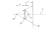
図1には中心射影方式の検査原理に基づく光学式位置測定装置の部分概要図が示されており、ここでは、光源1が反射式の測定目盛板2を照射するようになっている。この測定目盛板2は、位置測定装置が回転状の相対運動をするか、線形の相対運動をするかに応じて、線状及び回転目盛として形成されることができる。また、測定目盛板2に入射してくる照射ビーム束は、該測定目盛板2によって光源1方向へ反射され、検査面において光電的な検出装置3へ到達する。ここで、測定目盛板2は、光源1及び検出装置3に対して相対変位可能に配置されている。すなわち、測定目盛板は、線形の軸に沿って変位可能であるか、又は回転軸を中心として回転可能となっている。
FIG. 1 shows a partial schematic diagram of an optical position measuring apparatus based on the central projection type inspection principle. Here, a light source 1 irradiates a reflective
測定目盛板2が光源1及び検出装置3に対して相対回転する場合には、検査面において、変調された縞模様が得られ、この縞模様は、検出装置3によって、変位に応じた位置信号に変換可能である。
When the
このような位置測定装置によって、互いに変位(線形又は回転)する2つの物体の相対位置又は絶対位置を決定することが可能である。ここで、2つの物体のうちいずれかは測定目盛板2に接続され、他方は光源1及び検出装置3に接続されている。
With such a position measuring device it is possible to determine the relative or absolute position of two objects that are displaced (linearly or rotated) with respect to each other. Here, one of the two objects is connected to the
図1から分かるように、光源1は測定目盛板2から距離uだけ離間して配置されており、以下、この距離uを第1の距離という。また、検出装置3は測定目盛板2から距離vだけ離間して配置されており、以下、この距離vを第2の距離という。図1においては、第2の距離vは第1の距離uと異なっている。
As can be seen from FIG. 1, the light source 1 is arranged at a distance u from the
モデル的に、上述の検査用光路を、実際の光源1の代わりに測定目盛板2から第1の距離uだけ離間した仮想光源1’によって反対側から距離u’=u離間した位置から測定目盛板2を照射することが考えられる。この仮想光源1’から照射される照射ビーム束は、測定目盛板2の検査される目盛の検出面への中心射影を引き起こすものとなっている。
As a model, the above-described inspection optical path is measured from a position separated from the opposite side by a distance u ′ = u by a virtual light source 1 ′ separated from the
光学的な中心射影方式の検査原理に基づく回転式位置測定装置が例えば特許文献1に開示されている。この位置測定装置は光源、回転対称かつ反射性の測定目盛板を備えたインデックスディスク及び光電式の検出装置を含んで構成されており、インデックスディスクは、回転軸を中心として、光源及び検出装置に対して回転可能となっている。そのため、相対回転する際に、回転角度に応じた位置信号が検出装置によって検出可能となっている。 For example, Patent Document 1 discloses a rotary position measuring device based on an optical central projection inspection principle. This position measuring device is configured to include a light source, an index disk having a rotationally symmetric and reflective measurement scale plate , and a photoelectric detection device. The index disk is connected to the light source and the detection device around the rotation axis. It can be rotated. Therefore, when the relative rotation is performed, a position signal corresponding to the rotation angle can be detected by the detection device.
ここで位置信号を生成するために使用されている中心射影方式の検査原理は、いわゆる3格子システムと呼ばれ、例えば非特許文献1に開示されている。 Here, the central projection type inspection principle used for generating the position signal is called a so-called three-grid system, and is disclosed in Non-Patent Document 1, for example.
理想的な場合には、このような中心射影方式による検査においては、第1の距離u及び第2の距離vは同一のものとして選択される。ここで、位置測定装置の適当な構成要素は、光路中に適切に配置される。また、第1の距離u及び第2の距離vを同一に選択した場合には、生じ得る物体間あるいは測定目盛板2間の間隔すなわち検査距離の変化が検査面に生じた照射による結像の大きさに影響を及ぼさない。
In an ideal case, in such an inspection by the central projection method, the first distance u and the second distance v are selected to be the same. Here, suitable components of the position measuring device are appropriately arranged in the optical path. In addition, when the first distance u and the second distance v are selected to be the same, the distance between the objects that can occur or between the
しかしながら、実際には、第1の距離u及び第2の距離vが常に同一であることは保証されていない。すなわち、図1に示されているように、第1の距離uが第2の距離vと相違する、具体的には、u<vの関係となることがある。このような場合には、検査距離の変動が照射による結像の大きさの変化を生じさせてしまい、その結果、位置測定における誤差を招くこととなってしまう。 In practice, however, it is not guaranteed that the first distance u and the second distance v are always the same. That is, as shown in FIG. 1, the first distance u may be different from the second distance v. Specifically, there may be a relationship of u <v. In such a case, a change in the inspection distance causes a change in the size of the image formed by irradiation, resulting in an error in position measurement.
上記のような位置測定装置における他の問題は、測定目盛板上の汚れによる影響度に基づく問題である。 Another problem in the position measuring apparatus as described above is a problem based on the degree of influence due to dirt on the measurement scale plate .
本発明は上記問題に鑑みてなされたもので、その目的とするところは、中心射影方式に基づく回転式位置測定装置について、検査光路上における個々の構成部材間の最適でない間隔についてより影響度を抑え、及び/又は検査すべき測定目盛板の汚れの影響を極力受けないようにすることにある。 The present invention has been made in view of the above problems, and the object of the present invention is to provide a rotary position measurement device based on the central projection method and to have a greater influence on the non-optimal spacing between individual components on the inspection optical path. The object is to suppress and / or minimize the influence of dirt on the measurement scale plate to be inspected.
上記目的は、請求項1又は2に記載の特徴を備えた回転式位置測定装置によって達成される。また、本発明による回転式位置測定装置の他の実施形態は、各従属請求項に記載されている。
The object is achieved by a rotary position measuring device having the features of
本発明による回転式位置測定装置は、光源と、回転対称かつ反射性を有する測定目盛板を備えたインデックスディスクと、電光式の検出装置とを含んで成る回転式位置測定装置であって、前記インデックスディスクを前記光源及び前記検出装置に対して回転軸を中心として回転可能とし、相対回転時に回転角度に応じた位置信号を前記検出装置によって検出可能であり、前記回転軸上の前記光源を前記測定目盛板から第1の距離だけ離間させて配置し、前記検出装置を、前記第1の距離とは異なる第2の距離だけ前記測定目盛板から離間させて配置し、前記インデックスディスクを、光学手段を含むよう構成し、該光学手段を、前記光源の結像が前記第1の距離とは異なる第3の距離だけ前記測定目盛板から離間した位置に形成される光学的効果を有するよう構成したことを特徴としている。なお、このとき、第3の距離を第2の距離と同一にすることも可能である。 A rotary position measuring device according to the present invention is a rotary position measuring device comprising a light source, an index disk having a rotationally symmetric and reflective measurement scale plate , and an electro-optical detection device, The index disk can be rotated around the rotation axis with respect to the light source and the detection device, and a position signal corresponding to a rotation angle can be detected by the detection device at the time of relative rotation, and the light source on the rotation shaft is measured first distance moved away from the scale plate is disposed, said detecting device, arranged is separated only from the measuring graduation plate differs second distance from said first distance, said index disk, optical configured to include means, optical that said optical means, imaging of the light source is formed at a position spaced from the said measuring scale plate different third distance from said first distance It is characterized by being configured to have a fruit. At this time, the third distance may be the same as the second distance.
本発明による回転式位置測定装置の他の実施形態は、前記インデックスディスク上の光学手段を、所定の焦点距離を有する凹面鏡の光学的効果に対応する光学的効果を有するよう構成したことを特徴としている。 Another embodiment of the rotary position measuring device according to the present invention is characterized in that the optical means on the index disk has an optical effect corresponding to the optical effect of a concave mirror having a predetermined focal length. Yes.
このとき、前記インデックスディスク上の光学手段により前記光源の実像を任意の位置に形成し、該位置から照射される照射ビーム束が、まず前記検出装置を通過して前記測定目盛板に到達し、ここで反射された後、前記検出装置方向へ収束して伝播するよう構成することも可能である。 At this time, a real image of the light source is formed at an arbitrary position by optical means on the index disk , and an irradiation beam bundle irradiated from the position first passes through the detection device and reaches the measurement scale plate , It is also possible to configure so as to converge and propagate in the direction of the detection device after being reflected here.
また、本発明の他の実施形態は、前記インデックスディスク上の光学手段を、所定の焦点距離を有する凸面鏡の光学的効果に対応する光学的効果を有するよう構成したことを特徴としている。 Another embodiment of the present invention is characterized in that the optical means on the index disk has an optical effect corresponding to the optical effect of a convex mirror having a predetermined focal length.
さらに、前記測定目盛板を径方向目盛として形成し、該径方向目盛を、異なる反射特性を有し、かつ、円環状に配置された複数の目盛領域で構成することも考えられる。 Furthermore, forming the measuring graduation plate as radial graduation, the該径direction scale has different reflective properties, and is also conceivable to configure a plurality of memory areas disposed in an annular shape.
また、前記インデックスディスク上の比較的高い反射率を有する前記目盛領域を、該目盛領域に入射される照射ビーム束に対する光学的効果を有するよう構成することもできる。 Furthermore, the scale area having a relatively high reflectivity on the index disc, may be configured to have an optical effect with respect to the irradiation beam flux incident on the scale region.
また、前記光学手段を、回転対称の段状構造として前記インデックスディスクの支持基板上に形成することも可能である。 The optical means may be formed on the support substrate of the index disk as a rotationally symmetric stepped structure.
本発明による回転式位置検出装置の他の実施形態は、前記光源を、中間配置された光学要素を介すことなく前記測定目盛板を完全に照射するよう構成したことを特徴としている。 Another embodiment of the rotary position detection device according to the present invention is characterized in that the light source is configured to completely irradiate the measurement scale plate without an intermediate optical element.
さらに、前記検出装置を円環状の検出装置アセンブリを含んで構成するとともに、該検出装置アセンブリを前記回転軸を中心として円環状に配置された複数の検出要素で構成することも可能である。 Further, the detection device may include an annular detection device assembly, and the detection device assembly may include a plurality of detection elements arranged in an annular shape around the rotation axis.
本発明によれば、検査光路中における構成部材の距離の変化に対する影響度を大きく低減することが可能である。また、本発明によれば、例えば位置測定装置の誤った取付により生じ得る理想的な間隔からのずれが生じた場合であっても、十分なクオリティの位置信号を得ることが可能である。 According to the present invention, it is possible to greatly reduce the degree of influence on the change in the distance between constituent members in the inspection optical path. In addition, according to the present invention, it is possible to obtain a position signal of sufficient quality even when a deviation from an ideal interval that may occur due to, for example, incorrect mounting of the position measuring device occurs.
また、他の利点は、測定目盛板と検出装置の間で軸方向へ拡径する照射ビーム束により、回転角度に応じた位置信号を生成するために、非常に小さな検査面を検出装置において得ることが可能である。これにより、検出装置に対するコスト削減も図ることができる。さらに、このような光路により、測定目盛板に照射される領域が検出装置へ結像される範囲よりも大きいため、測定目盛板に生じ得る汚れによる影響度を大幅に低減することも可能である。 Another advantage is that a very small inspection surface is obtained in the detection device in order to generate a position signal in accordance with the rotation angle by the irradiation beam bundle that expands in the axial direction between the measurement scale plate and the detection device. It is possible. Thereby, the cost reduction with respect to a detection apparatus can also be aimed at. Further, such a light path, is larger than the range area illuminated on the measuring graduation plate is imaged to the detection device, it is also possible to significantly reduce the influence due to contamination which may occur in the measurement graduation plate is there.
本発明による他の利点は、以下の図面を用いた説明において明らかにする。 Other advantages of the present invention will become apparent in the following description with the drawings.
以下に本発明の実施の形態を添付図面に基づいて説明する。 Embodiments of the present invention will be described below with reference to the accompanying drawings.
<実施の形態1>
図2には、本発明による回転式位置測定装置の第1の実施形態が図1と同様に部分的かつ概略的に示されている。
<Embodiment 1>
FIG. 2 partially and schematically shows a first embodiment of the rotary position measuring device according to the present invention, as in FIG.
回転式位置測定装置の図示の実施形態においては光源10が設けられており、この光源10は、回転対称で反射性を有する測定目盛板20を備えたインデックスディスクを照射するものとなっている。光源10と測定目盛板20の間には他の光学要素が配置されておらず、本発明による回転式位置測定装置のコンパクト化を図ることが可能となっている。インデックスディスク上の測定目盛板20は径方向目盛として形成されており、この径方向目盛は、回転軸Rの周囲に環状に配置されつつ様々な反射特性を有する目盛領域で構成されている。
In the illustrated embodiment of the rotary position measuring device, a
ここで、測定目盛板20としては、周期的に配置されつつ様々な反射率を有する目盛領域を備えたインクリメンタル目盛や、非周期的に配置されつつ異なる周期性を有するアブソリュート目盛などが考えられる。また、照射される照射ビーム束は、回転対称であり完全に照射される測定目盛板20によって光源10へ向けて反射され、検出面において、回転対称の光電式の検出装置30へ至る。測定目盛板20を備えたインデックスディスクは、光源10及び検出装置30に対して、回転軸Rを中心に回転可能となっている。測定目盛板20を備えたインデックスディスクの光源10及び検出装置30に対する相対回転時には、検出面において、環状かつ変調された縞模様が生じる。そして、この縞模様は、検出装置30によって、回転角度に応じた位置信号に変換される。
Here, as the
このような回転式位置測定装置によって、回転軸Rを中心に回転可能な2つの物体の互いの相対位置又は絶対位置を検出することが可能である。これら2つの物体のうちいずれかがここではインデックスディスクあるいは測定目盛板20に接続されている一方、他方は光源10及び検出装置30に接続されている。なお、これら2つの物体としては、互いに相対回転する機械部品が考えられる。また、位置測定装置により生成される位置信号は機械制御に用いられ、この機械制御は、例えば対応する機械部品の位置決めに用いられる。
With such a rotary position measuring device, it is possible to detect the relative position or absolute position of two objects that can rotate around the rotation axis R. One of these two objects is here connected to the index disk or the measuring
図2に示すように、光源10は、回転軸R上において測定目盛板20との間に第1の距離uをもって配置されている。また、検出装置30は、測定目盛板20から第2の距離vをもって配置されている。ここで、第2の距離vは、第1の距離uと異なるように設定されている。
As shown in FIG. 2, the
本発明においてはインデックスディスクに複数の光学手段が設けられているか、又は統合されており、これら光学手段は、光源10の像を回転軸R上のある位置に形成するものとなっている。また、この像は測定目盛板20から第3の距離u’だけ離間しており、この第3の距離u’も第1の距離uとは異なるものとなっている。図2には、この位置に結像された光源すなわち光源の像が符号10’を付して示されているとともに、この位置から照射される光路が破線で示されている。
In the present invention, the index disk is provided with or integrated with a plurality of optical means, and these optical means form an image of the
図示の実施形態においては、適当な光学手段が、第3の距離u’が第2の距離vと同一となるようインデックスディスクにおいて寸法設定されている。しかしながら、後述するように、第2の距離vと同一となるよう第3の距離u’を設定することは、本発明において必須のものではない。すなわち、本発明における回転式位置測定装置において、第3の距離u’を他の方法で選択してもよい。 In the illustrated embodiment, suitable optical means are dimensioned on the index disk such that the third distance u ′ is the same as the second distance v. However, as will be described later, setting the third distance u ′ so as to be the same as the second distance v is not essential in the present invention. That is, in the rotary position measurement device according to the present invention, the third distance u ′ may be selected by another method.
インデックスディスクに統合された光学手段は、それぞれ所定の焦点距離fを有する凹面鏡又は凸面鏡の光学的効果を有している。図2に示す実施例においては、インデックスディスク上の適当な光学手段を介して凹面鏡の光学的効果が得られるようになっており、この凹面鏡の焦点距離は、凹面鏡による結像時の対物距離よりも大きくなるよう設定されている。これにより、光源10の結像が回転軸R上のある位置に仮想の光源10’としてなされる。なお、回転軸R上のある位置は、測定目盛板20から第3の距離u’だけ離間している。
The optical means integrated in the index disk has the optical effect of a concave mirror or convex mirror each having a predetermined focal length f. In the embodiment shown in FIG. 2, the optical effect of the concave mirror is obtained through appropriate optical means on the index disk. The focal length of this concave mirror is based on the objective distance at the time of image formation by the concave mirror. Is set to be larger. Thereby, the image of the
以下に、本実施の形態についてのインデックスディスクにおける凹面鏡あるいは適当な光学手段の焦点距離fをどのように算出するか説明する。なお、焦点距離fは、第3の距離u’において仮想光源10’を得るために必要である。
第1の距離及び第2の距離をそれぞれu、vとすると、拡大係数(Abbildungsmassstab)m1,2は、
m1,2=u/(2v)±Sqrt((u/(2v))2−1) (式1)
という関係となる。
Hereinafter, how to calculate the focal length f of the concave mirror or appropriate optical means in the index disk according to the present embodiment will be described. The focal length f is necessary to obtain the virtual
When the first distance and the second distance are u and v, respectively, the expansion coefficient (Abildungsmasstab) m 1 , 2 is
m 1,2 = u / (2v) ± Sqrt ((u / (2v)) 2 -1) (Formula 1)
It becomes the relationship.
必要な第3の距離u’は、
u’=m1,2・u (式2)
となる。
The required third distance u ′ is
u ′ = m 1,2 · u (Formula 2)
It becomes.
そして、凹面鏡に対して必要な焦点距離は、
1/u+1/u’=1/f (式3)
から算出される。
And the required focal length for the concave mirror is
1 / u + 1 / u ′ = 1 / f (Formula 3)
Is calculated from
インデックスディスクにおける適当な光学手段によって、結果的に、上記のように算出される焦点距離fを有する凹面鏡の光学的効果が保証されることになる。そのため、光源10の仮想の結像が所望の位置に形成されることになる。
Appropriate optical means in the index disk consequently guarantees the optical effect of the concave mirror having the focal length f calculated as described above. Therefore, virtual imaging of the
本発明による回転式位置測定装置の図2に示す第1の実施形態の具体的な構成を、図3a,図3b,図4a及び図4bに基づいて説明する。ここで、図3a及び図3bには位置測定装置全体の異なる一部を示されており、図4a及び図4bには測定目盛板を含むインデックスディスクの異なる角度から見た図が示されている。 A specific configuration of the first embodiment shown in FIG. 2 of the rotary position measuring apparatus according to the present invention will be described with reference to FIGS. 3a, 3b, 4a and 4b. Here, FIGS. 3a and 3b show different parts of the entire position measuring device, and FIGS. 4a and 4b show views of the index disk including the measurement scale plate seen from different angles. .
位置測定装置のケーシング700内における固定された回路ボード500上には検出装置300が配置されており、この検出装置300上の中心部には光源100が配置されている。検出装置300と光源100は、ボンディングワイヤ400を介して、回路ボード500における不図示の信号伝達ケーブルに接続されている。また、回路ボード500は、ケーブル600を介して不図示の後続の電子機器に結合されている。また、ケーブル600によって、生成された位置信号が伝達されるとともに、位置測定装置内の電子部品に電力供給がなされるようになっている。
A
特に図3bに示すように、検出装置300は円環状の検出装置アセンブリ310を含んで構成されており、この検出装置アセンブリ310は、回転軸Rを中心として一定間隔に配置された各検出要素で構成されている。
In particular, as shown in FIG. 3 b, the
また、ケーシング700内においてインデックスディスク210が回転軸Rを中心として回転可能に配置されており、このインデックスディスク210は、その検出装置300と対向する側において反射性の測定目盛板200を支持している。このインデックスディスク210には光学手段が統合されており、この光学手段は、上述のような光学的効果すなわち光源100がある位置に結像されるという効果を有している。また、この結像は、測定目盛板200から第3の距離u’だけ離間している。具体的な本実施の形態において、光学手段は、インデックスディスク210において、このインデックスディスク210が図2に示す実施例に基づく凹面鏡のような光学的効果を有するよう、すなわち得られる第3の距離u’が第2の距離vと同一となるよう形成されている。
An
本実施の形態におけるインデックスディスク210の平面図が図4aに示されており、このインデックスディスク210の部分断面図が図4bに示されている。図4aに示すように、例えばガラス、金属、合成樹脂などで形成された支持基板上のインデックスディスク210上には反射性の測定目盛板200がインクリメンタル目盛として配置されており、このインクリメンタル目盛は、回転軸Rを中心として円環状に配置され、かつ、異なる反射特性を有する複数の目盛領域220a,220bで構成されている。測定目盛板200において暗色で示された目盛領域220aは、本実施の形態において、これらの間に配置された目盛領域220bよりも小さな反射率を有している。ここで、目盛領域220aを、これにおいて反射された光が検出装置に到達しないように形成することが考えられる。
A plan view of the
図4aに示すインデックスディスク210上の同心円は、比較的高い反射率を有する目盛領域220bにおける回転対称の構造あるいは径方向への段状構造の境界部を示している。なお、この目盛領域220bは、図4bにおける部分断面図に示されている。また、インデックスディスク210におけるこの径方向への段状構造により、本実施の形態においては、光源100の所定の結像を得るための光学手段が形成されている。この段状構造の具体的な形成、すなわち、回転対称の段状構造の段の高さ、段の幅及び段の同心性の選択によって、インデックスディスク210が回折性の凹面鏡に対して所定の焦点距離を有することになる。そして、この凹面鏡によって、上述のように、光源100の結像が得られることになる。ここで、段状構造の重要なパラメータの選択は、二点間結像に対する回折要素に対する公知の原理に基づいている。
The concentric circles on the
目盛210の製造は、例えば、まず、反射性の支持基板上で回転対称の段状構造を適当な層及び石版上の構造の分離によって形成することによってなされる。次に、例えば適当な吸収性の材料を分離することで、その上に比較的小さな反射率を有する径方向目盛の目盛領域が形成される。
The
これに代えて、例えばCDの製造において知られている技術によってインデックスディスク210を形成してもよい。この場合、比較的小さな反射率を有する目盛領域には回折性の微細構造が設けられ、この微細構造によって、この微細構造に入射する光が検出装置に到達せずに空間方向へ回折されることが保証される。このような微細構造は、回転対称の段状構造としても、例えばまず透明な合成樹脂に成形され、次に良好な反射性を有する例えばアルミニウムや金などの金属層を取り付けられる。
Alternatively, the
ところで、本発明による回転式位置測定装置の本実施の形態において、インデックスディスクにおける凹面鏡として形成された光学手段の代わりに、インデックスディスクにおける適当な段状構造によって光学的効果を得るようにしてもよい。この光学的効果は凸面鏡に相当し、この凸面鏡の焦点距離は、凹面鏡による結像時の対物距離よりも大きくなるよう設定されている。 Incidentally, in this embodiment of the rotary position measuring device according to the present invention, instead of optical means formed as a concave mirror in the index disc, by a suitable stepped structure in the index disc may be obtained an optical effect . This optical effect corresponds to a convex mirror, and the focal length of this convex mirror is set to be larger than the objective distance during imaging by the concave mirror.
<実施の形態2>
本発明による回転式位置測定装置の第2の実施形態を図5に基づいて説明する。この図5は、本実施の形態における光路を示す図2と同様な図である。
<
A second embodiment of the rotary position measuring device according to the present invention will be described with reference to FIG. FIG. 5 is a view similar to FIG. 2 showing the optical path in the present embodiment.
ここでも、測定目盛板2000に対して第1の距離uだけ離間した光源1000が回転軸R上に配置されている。第1の実施形態と同様に、測定目盛板2000から第2の距離vだけ離間して検出装置3000が配置されている。測定目盛板2000は、ここでも反射性の径方向目盛として形成されている。
Again, the
上述の実施形態と異なり、本実施形態においては光学手段がインデックスディスク内に形成されており、この光学手段は、光源1000の結像を所定の位置に形成するようになっている。そして、この光源1000は、測定目盛板2000から第3の距離u’だけ離間した位置に配置されている。また、第1の実施形態においては凹面鏡として機能する光学手段によって仮想光源が形成されている一方、本実施の形態においてはインデックスディスク内に形成された光学手段によって光源の実像1000’が形成される。このとき、光源の実像1000’の検出装置3000からの距離は、第4の距離wに相当する。この第4の距離wは、測定目盛板2000と検出装置3000との間の第2の距離vと同一となっている。また、得られる第3の距離u’は、ここでは上述の実施形態と同様に、第2の距離vと同一となっていない。光学手段は、本実施の形態においても凹面鏡として形成されているが、上述の実施形態と異なり、この凹面鏡の焦点距離は対物距離よりも小さく設定されている。
Unlike the above-described embodiment, in this embodiment, the optical means is formed in the index disk, and this optical means forms the image of the
光源の実像1000’の位置に起因して、この実像1000’から照射される照射ビーム束は図5に示すようにまず検出装置3000を通過して測定目盛板2000へ至り、ここで反射されて検出装置3000方向へ収束して伝播する。
'Due to the position of the real image 1000' real 1000 light source illumination beam bundle emitted from the reach to the
本実施の形態においては第1の距離uと第2の距離vの一致は保証されておらず、これにより、中心射影方式の検査原理に基づき、起こり得る測定目盛板2000と検出装置3000の間の変化の際に、検査面において生じる照射による結像の大きさに変化が生じる。照射による結像の直径が変化してもこの照射による結像における暗部と明部の移行領域の位置は変化しないため、このような変化は、本発明による回転対称な検査面への結像時において大きな問題とはならない。
In the present embodiment, the coincidence between the first distance u and the second distance v is not guaranteed, so that, based on the central projection method inspection principle, the possible
また、本実施の形態の利点は、検査距離の変動に依存しないことではなく、測定目盛板2000と検出装置の間に収束する光路が存在するという事実にある。すなわち、測定目盛板の構造は、検査面に縮小されて結像され、従来のこのようなシステムに比して検出装置3000における検査面の大きさを小さくすることができる。さらに、これにより、検査すべき測定目盛板2000に生じ得る汚れの影響をより受けにくくすることができる。
The advantage of this embodiment is not to depend on the variation of the inspection distance, but to the fact that there is a convergent optical path between the
なお、本発明は上述の実施の形態に限られず、本発明の範囲を逸脱しない限り他の実施の形態も考えられる。 The present invention is not limited to the above-described embodiment, and other embodiments can be considered without departing from the scope of the present invention.
1 光源
1’ 仮想光源
2 測定目盛板
3 検出装置
10 光源
10’ 仮想光源
20 測定目盛板
30 検出装置
100 光源
200 測定目盛板
210 インデックスディスク
220a,220b 目盛領域
300 検出装置
310 検出装置アセンブリ
400 ボンディングワイヤ
500 回路ボード
600 ケーブル
700 ケーシング
1000 光源
1000’ 仮想光源
2000 測定目盛板
3000 検出装置
f 焦点距離
R 回転軸
u 第1の距離
v 第2の距離
u’ 第3の距離
w 第4の距離
DESCRIPTION OF SYMBOLS 1 Light source 1 'Virtual
Claims (9)
回転対称かつ反射性を有する測定目盛板(20;200;2000)を備えたインデックスディスク(210)と、
電光式の検出装置(30;300;3000)と
を備えて成る回転式位置測定装置であって、
前記インデックスディスク(210)を前記光源(10;100;1000)及び前記検出装置に対して回転軸(R)を中心として回転可能とし、相対回転時に回転角度に応じた位置信号を前記検出装置(30;300;3000)によって検出可能であり、
前記回転軸(R)上の前記光源(10;100;1000)を前記測定目盛板(20;200;2000)から第1の距離(u)だけ離間させて配置し、
前記検出装置(30;300;3000)を、前記第1の距離(u)とは異なる第2の距離(v)だけ前記測定目盛板(20;200;2000)から離間させて配置し、
前記インデックスディスクを、光学手段を含むよう構成し、該光学手段を、前記光源(10;100;1000)の結像が前記第1の距離(u)とは異なる第3の距離(u’)だけ前記測定目盛板(20;200;2000)から離間した位置に形成される光学的効果を有するよう構成し、
前記測定目盛板(20;200;2000)を径方向目盛として形成し、該径方向目盛を、異なる反射特性を有し、かつ、円環状に配置された複数の目盛領域(220a,220b)で構成した
ことを特徴とする回転式位置測定装置。 A light source (10; 100; 1000);
An index disk (210) with a rotationally symmetrical and reflective measuring scale plate (20; 200; 2000);
A rotary position measuring device comprising an electro-optical detection device (30; 300; 3000),
The index disk (210) can be rotated around the rotation axis (R) with respect to the light source (10; 100; 1000) and the detection device, and a position signal corresponding to a rotation angle at the time of relative rotation is detected by the detection device ( 30; 300; 3000)
The light source (10; 100; 1000) on the rotation axis (R) is spaced apart from the measurement scale plate (20; 200; 2000) by a first distance (u);
The detector (30; 300; 3000) is spaced apart from the measurement scale plate (20; 200; 2000) by a second distance (v) different from the first distance (u);
The index disk is configured to include optical means, and the optical means is configured to have a third distance (u ′) in which the image of the light source (10; 100; 1000) is different from the first distance (u). Only having an optical effect formed at a position spaced from the measurement scale plate (20; 200; 2000) ,
The measurement scale plate (20; 200; 2000) is formed as a radial scale, and the radial scale has a plurality of scale regions (220a, 220b) having different reflection characteristics and arranged in an annular shape. rotary position measuring apparatus characterized by constituting the <br/>.
回転対称かつ反射性を有する測定目盛板(20;200;2000)を備えたインデックスディスク(210)と、An index disk (210) with a rotationally symmetrical and reflective measuring scale plate (20; 200; 2000);
電光式の検出装置(30;300;3000)とA lightning detector (30; 300; 3000);
を備えて成る回転式位置測定装置であって、A rotary position measuring device comprising:
前記インデックスディスク(210)を前記光源(10;100;1000)及び前記検出装置に対して回転軸(R)を中心として回転可能とし、相対回転時に回転角度に応じた位置信号を前記検出装置(30;300;3000)によって検出可能であり、The index disk (210) can be rotated around the rotation axis (R) with respect to the light source (10; 100; 1000) and the detection device, and a position signal corresponding to a rotation angle at the time of relative rotation is detected by the detection device ( 30; 300; 3000)
前記回転軸(R)上の前記光源(10;100;1000)を前記測定目盛板(20;200;2000)から第1の距離(u)だけ離間させて配置し、The light source (10; 100; 1000) on the rotation axis (R) is spaced apart from the measurement scale plate (20; 200; 2000) by a first distance (u);
前記検出装置(30;300;3000)を、前記第1の距離(u)とは異なる第2の距離(v)だけ前記測定目盛板(20;200;2000)から離間させて配置し、The detector (30; 300; 3000) is spaced apart from the measurement scale plate (20; 200; 2000) by a second distance (v) different from the first distance (u);
前記インデックスディスクを、光学手段を含むよう構成し、該光学手段を、前記光源(10;100;1000)の結像が前記第1の距離(u)とは異なる第3の距離(u’)だけ前記測定目盛板(20;200;2000)から離間した位置に形成される光学的効果を有するよう構成し、The index disk is configured to include optical means, and the optical means is configured to have a third distance (u ′) in which the image of the light source (10; 100; 1000) is different from the first distance (u). Only having an optical effect formed at a position spaced from the measurement scale plate (20; 200; 2000),
前記光学手段を、回転対称の段状構造として前記インデックスディスク(210)の支持基板上に形成したThe optical means is formed on a support substrate of the index disk (210) as a rotationally symmetric stepped structure.
ことを特徴とする回転式位置測定装置。A rotary position measuring device.
Applications Claiming Priority (2)
| Application Number | Priority Date | Filing Date | Title |
|---|---|---|---|
| DE201110082570 DE102011082570A1 (en) | 2011-09-13 | 2011-09-13 | Rotary position measuring device |
| DE102011082570.3 | 2011-09-13 |
Publications (3)
| Publication Number | Publication Date |
|---|---|
| JP2013061330A JP2013061330A (en) | 2013-04-04 |
| JP2013061330A5 JP2013061330A5 (en) | 2015-10-29 |
| JP6246460B2 true JP6246460B2 (en) | 2017-12-13 |
Family
ID=46801323
Family Applications (1)
| Application Number | Title | Priority Date | Filing Date |
|---|---|---|---|
| JP2012195723A Active JP6246460B2 (en) | 2011-09-13 | 2012-09-06 | Rotary position detector |
Country Status (5)
| Country | Link |
|---|---|
| US (1) | US8937726B2 (en) |
| EP (1) | EP2570780B1 (en) |
| JP (1) | JP6246460B2 (en) |
| CN (1) | CN102997948B (en) |
| DE (1) | DE102011082570A1 (en) |
Families Citing this family (3)
| Publication number | Priority date | Publication date | Assignee | Title |
|---|---|---|---|---|
| DE102012222077A1 (en) | 2012-12-03 | 2014-06-05 | Dr. Johannes Heidenhain Gmbh | Position measuring device |
| DE102016224012A1 (en) * | 2016-12-02 | 2018-06-07 | Dr. Johannes Heidenhain Gmbh | Position measuring device and method for operating a position measuring device |
| JP7120200B2 (en) * | 2019-10-15 | 2022-08-17 | 株式会社デンソー | Rotation angle detector |
Family Cites Families (22)
| Publication number | Priority date | Publication date | Assignee | Title |
|---|---|---|---|---|
| US4572952A (en) * | 1982-07-28 | 1986-02-25 | Adrian March Research Ltd. | Position sensor with moire interpolation |
| US4844617A (en) * | 1988-01-20 | 1989-07-04 | Tencor Instruments | Confocal measuring microscope with automatic focusing |
| JPH07888Y2 (en) * | 1988-02-22 | 1995-01-11 | 株式会社ミツトヨ | Optical displacement detector |
| JP2749900B2 (en) * | 1989-09-11 | 1998-05-13 | 株式会社三協精機製作所 | Position detection method |
| JP2653186B2 (en) * | 1989-09-27 | 1997-09-10 | キヤノン株式会社 | Head-up display device |
| JP3500214B2 (en) * | 1994-12-28 | 2004-02-23 | 日本電産コパル株式会社 | Optical encoder |
| JPH09105625A (en) * | 1995-10-13 | 1997-04-22 | Topcon Corp | Distance-measuring apparatus |
| JP3509830B2 (en) | 1995-11-08 | 2004-03-22 | 株式会社安川電機 | Optical rotary encoder |
| JPH1123321A (en) * | 1997-06-30 | 1999-01-29 | Canon Inc | Optical scale and displacement-information measuring apparatus unit the same |
| JP3459755B2 (en) * | 1997-06-30 | 2003-10-27 | キヤノン株式会社 | Displacement information measuring device |
| EP0978708B1 (en) * | 1998-08-01 | 2005-10-05 | Dr. Johannes Heidenhain GmbH | Rotary encoder |
| DE19908328A1 (en) * | 1999-02-26 | 2000-08-31 | Heidenhain Gmbh Dr Johannes | Optical position measurement equipment has scanning unit and measurement scale having at least two measurement divisions |
| JP2002139353A (en) * | 2000-11-06 | 2002-05-17 | Olympus Optical Co Ltd | Optical rotary encoder |
| GB0103582D0 (en) * | 2001-02-14 | 2001-03-28 | Renishaw Plc | Position determination system |
| EP1396704B1 (en) * | 2002-08-07 | 2015-10-07 | Dr. Johannes Heidenhain GmbH | Interferential position measuring device |
| DE102006021017A1 (en) * | 2006-05-05 | 2007-11-08 | Dr. Johannes Heidenhain Gmbh | Position measuring device |
| DE102006042743A1 (en) * | 2006-09-12 | 2008-03-27 | Dr. Johannes Heidenhain Gmbh | Position measuring device |
| JP2008292352A (en) * | 2007-05-25 | 2008-12-04 | Mitsutoyo Corp | Reflection type encoder |
| JP2009210374A (en) * | 2008-03-04 | 2009-09-17 | Nikon Corp | Encoder and light receiving unit |
| DE102008025870A1 (en) * | 2008-05-31 | 2009-12-03 | Dr. Johannes Heidenhain Gmbh | Optical position measuring device |
| DE102008044858A1 (en) * | 2008-08-28 | 2010-03-04 | Dr. Johannes Heidenhain Gmbh | Optical position measuring device |
| DE102010029211A1 (en) * | 2010-05-21 | 2011-11-24 | Dr. Johannes Heidenhain Gmbh | Optical position measuring device |
-
2011
- 2011-09-13 DE DE201110082570 patent/DE102011082570A1/en not_active Withdrawn
-
2012
- 2012-08-29 EP EP12182164.9A patent/EP2570780B1/en active Active
- 2012-09-05 US US13/603,846 patent/US8937726B2/en active Active
- 2012-09-06 JP JP2012195723A patent/JP6246460B2/en active Active
- 2012-09-13 CN CN201210338229.7A patent/CN102997948B/en active Active
Also Published As
| Publication number | Publication date |
|---|---|
| CN102997948A (en) | 2013-03-27 |
| EP2570780B1 (en) | 2018-01-03 |
| US20130063732A1 (en) | 2013-03-14 |
| JP2013061330A (en) | 2013-04-04 |
| US8937726B2 (en) | 2015-01-20 |
| EP2570780A3 (en) | 2017-01-11 |
| EP2570780A2 (en) | 2013-03-20 |
| DE102011082570A1 (en) | 2013-03-14 |
| CN102997948B (en) | 2016-06-29 |
Similar Documents
| Publication | Publication Date | Title |
|---|---|---|
| JP6044315B2 (en) | Displacement measuring method and displacement measuring apparatus | |
| KR102198743B1 (en) | Simultaneous multi-angle spectroscopy | |
| KR101966572B1 (en) | Method and device for detecting overlay errors | |
| CN112262345B (en) | Measuring apparatus | |
| US20200124977A1 (en) | Method and Apparatus for Detecting Substrate Surface Variations | |
| KR20170121253A (en) | Method and apparatus for inspection and measurement | |
| US9989864B2 (en) | Lithographic method and apparatus | |
| JP6246460B2 (en) | Rotary position detector | |
| JP2010121960A (en) | Measuring device and method of measuring subject | |
| US10747120B2 (en) | Lithographic method and apparatus | |
| JP2013061330A5 (en) | ||
| JP2008135745A (en) | Wave front aberration measuring device and projection aligner | |
| JP2014115144A (en) | Shape measurement apparatus, optical device, method of manufacturing shape measurement apparatus, structure manufacturing system, and structure manufacturing method | |
| JPH0835859A (en) | Encoder device | |
| JP6042213B2 (en) | Concave optical element measuring device, concave diffraction grating measuring device, and planar diffraction grating measuring device | |
| JP5249391B2 (en) | Method and apparatus for measuring the surface profile of an object | |
| JP2010025876A (en) | Micro-distance measuring method and device | |
| JP5973472B2 (en) | Lithographic apparatus, method for measuring radiation beam spot focus, and device manufacturing method | |
| JP2007178281A (en) | Tilt sensor and encoder | |
| US11467506B2 (en) | Two-dimensional position encoder | |
| JP2007033098A (en) | Lens measuring method and lens measuring instrument | |
| JP5548151B2 (en) | Pattern shape inspection method and apparatus | |
| JP2009300236A (en) | Displacement detecting device | |
| JP3989656B2 (en) | Optical unit adjustment method and optical unit adjustment device | |
| JP2022106320A (en) | Optical device |
Legal Events
| Date | Code | Title | Description |
|---|---|---|---|
| A521 | Request for written amendment filed |
Free format text: JAPANESE INTERMEDIATE CODE: A523 Effective date: 20150904 |
|
| A621 | Written request for application examination |
Free format text: JAPANESE INTERMEDIATE CODE: A621 Effective date: 20150904 |
|
| A977 | Report on retrieval |
Free format text: JAPANESE INTERMEDIATE CODE: A971007 Effective date: 20160713 |
|
| A131 | Notification of reasons for refusal |
Free format text: JAPANESE INTERMEDIATE CODE: A131 Effective date: 20160720 |
|
| A521 | Request for written amendment filed |
Free format text: JAPANESE INTERMEDIATE CODE: A523 Effective date: 20160907 |
|
| A131 | Notification of reasons for refusal |
Free format text: JAPANESE INTERMEDIATE CODE: A131 Effective date: 20170215 |
|
| A521 | Request for written amendment filed |
Free format text: JAPANESE INTERMEDIATE CODE: A523 Effective date: 20170502 |
|
| TRDD | Decision of grant or rejection written | ||
| A01 | Written decision to grant a patent or to grant a registration (utility model) |
Free format text: JAPANESE INTERMEDIATE CODE: A01 Effective date: 20171018 |
|
| A61 | First payment of annual fees (during grant procedure) |
Free format text: JAPANESE INTERMEDIATE CODE: A61 Effective date: 20171115 |
|
| R150 | Certificate of patent or registration of utility model |
Ref document number: 6246460 Country of ref document: JP Free format text: JAPANESE INTERMEDIATE CODE: R150 |
|
| R250 | Receipt of annual fees |
Free format text: JAPANESE INTERMEDIATE CODE: R250 |
|
| R250 | Receipt of annual fees |
Free format text: JAPANESE INTERMEDIATE CODE: R250 |
|
| R250 | Receipt of annual fees |
Free format text: JAPANESE INTERMEDIATE CODE: R250 |
|
| R250 | Receipt of annual fees |
Free format text: JAPANESE INTERMEDIATE CODE: R250 |