JP6245512B2 - Image forming apparatus - Google Patents
Image forming apparatus Download PDFInfo
- Publication number
- JP6245512B2 JP6245512B2 JP2013232992A JP2013232992A JP6245512B2 JP 6245512 B2 JP6245512 B2 JP 6245512B2 JP 2013232992 A JP2013232992 A JP 2013232992A JP 2013232992 A JP2013232992 A JP 2013232992A JP 6245512 B2 JP6245512 B2 JP 6245512B2
- Authority
- JP
- Japan
- Prior art keywords
- sheet
- separation
- roller
- feeding
- rotating body
- Prior art date
- Legal status (The legal status is an assumption and is not a legal conclusion. Google has not performed a legal analysis and makes no representation as to the accuracy of the status listed.)
- Expired - Fee Related
Links
Images


Classifications
-
- G—PHYSICS
- G03—PHOTOGRAPHY; CINEMATOGRAPHY; ANALOGOUS TECHNIQUES USING WAVES OTHER THAN OPTICAL WAVES; ELECTROGRAPHY; HOLOGRAPHY
- G03G—ELECTROGRAPHY; ELECTROPHOTOGRAPHY; MAGNETOGRAPHY
- G03G15/00—Apparatus for electrographic processes using a charge pattern
- G03G15/65—Apparatus which relate to the handling of copy material
- G03G15/6529—Transporting
-
- G—PHYSICS
- G03—PHOTOGRAPHY; CINEMATOGRAPHY; ANALOGOUS TECHNIQUES USING WAVES OTHER THAN OPTICAL WAVES; ELECTROGRAPHY; HOLOGRAPHY
- G03G—ELECTROGRAPHY; ELECTROPHOTOGRAPHY; MAGNETOGRAPHY
- G03G15/00—Apparatus for electrographic processes using a charge pattern
- G03G15/65—Apparatus which relate to the handling of copy material
- G03G15/6502—Supplying of sheet copy material; Cassettes therefor
- G03G15/6511—Feeding devices for picking up or separation of copy sheets
-
- B—PERFORMING OPERATIONS; TRANSPORTING
- B65—CONVEYING; PACKING; STORING; HANDLING THIN OR FILAMENTARY MATERIAL
- B65H—HANDLING THIN OR FILAMENTARY MATERIAL, e.g. SHEETS, WEBS, CABLES
- B65H1/00—Supports or magazines for piles from which articles are to be separated
- B65H1/26—Supports or magazines for piles from which articles are to be separated with auxiliary supports to facilitate introduction or renewal of the pile
- B65H1/266—Support fully or partially removable from the handling machine, e.g. cassette, drawer
-
- B—PERFORMING OPERATIONS; TRANSPORTING
- B65—CONVEYING; PACKING; STORING; HANDLING THIN OR FILAMENTARY MATERIAL
- B65H—HANDLING THIN OR FILAMENTARY MATERIAL, e.g. SHEETS, WEBS, CABLES
- B65H3/00—Separating articles from piles
- B65H3/46—Supplementary devices or measures to assist separation or prevent double feed
- B65H3/52—Friction retainers acting on under or rear side of article being separated
- B65H3/5207—Non-driven retainers, e.g. movable retainers being moved by the motion of the article
- B65H3/5215—Non-driven retainers, e.g. movable retainers being moved by the motion of the article the retainers positioned under articles separated from the top of the pile
-
- B—PERFORMING OPERATIONS; TRANSPORTING
- B65—CONVEYING; PACKING; STORING; HANDLING THIN OR FILAMENTARY MATERIAL
- B65H—HANDLING THIN OR FILAMENTARY MATERIAL, e.g. SHEETS, WEBS, CABLES
- B65H5/00—Feeding articles separated from piles; Feeding articles to machines
- B65H5/06—Feeding articles separated from piles; Feeding articles to machines by rollers or balls, e.g. between rollers
- B65H5/062—Feeding articles separated from piles; Feeding articles to machines by rollers or balls, e.g. between rollers between rollers or balls
-
- B—PERFORMING OPERATIONS; TRANSPORTING
- B65—CONVEYING; PACKING; STORING; HANDLING THIN OR FILAMENTARY MATERIAL
- B65H—HANDLING THIN OR FILAMENTARY MATERIAL, e.g. SHEETS, WEBS, CABLES
- B65H9/00—Registering, e.g. orientating, articles; Devices therefor
- B65H9/16—Inclined tape, roller, or like article-forwarding side registers
- B65H9/166—Roller
-
- B—PERFORMING OPERATIONS; TRANSPORTING
- B65—CONVEYING; PACKING; STORING; HANDLING THIN OR FILAMENTARY MATERIAL
- B65H—HANDLING THIN OR FILAMENTARY MATERIAL, e.g. SHEETS, WEBS, CABLES
- B65H2301/00—Handling processes for sheets or webs
- B65H2301/40—Type of handling process
- B65H2301/42—Piling, depiling, handling piles
- B65H2301/423—Depiling; Separating articles from a pile
- B65H2301/4234—Depiling; Separating articles from a pile assisting separation or preventing double feed
-
- B—PERFORMING OPERATIONS; TRANSPORTING
- B65—CONVEYING; PACKING; STORING; HANDLING THIN OR FILAMENTARY MATERIAL
- B65H—HANDLING THIN OR FILAMENTARY MATERIAL, e.g. SHEETS, WEBS, CABLES
- B65H7/00—Controlling article feeding, separating, pile-advancing, or associated apparatus, to take account of incorrect feeding, absence of articles, or presence of faulty articles
- B65H7/02—Controlling article feeding, separating, pile-advancing, or associated apparatus, to take account of incorrect feeding, absence of articles, or presence of faulty articles by feelers or detectors
- B65H7/06—Controlling article feeding, separating, pile-advancing, or associated apparatus, to take account of incorrect feeding, absence of articles, or presence of faulty articles by feelers or detectors responsive to presence of faulty articles or incorrect separation or feed
- B65H7/12—Controlling article feeding, separating, pile-advancing, or associated apparatus, to take account of incorrect feeding, absence of articles, or presence of faulty articles by feelers or detectors responsive to presence of faulty articles or incorrect separation or feed responsive to double feed or separation
-
- G—PHYSICS
- G03—PHOTOGRAPHY; CINEMATOGRAPHY; ANALOGOUS TECHNIQUES USING WAVES OTHER THAN OPTICAL WAVES; ELECTROGRAPHY; HOLOGRAPHY
- G03G—ELECTROGRAPHY; ELECTROPHOTOGRAPHY; MAGNETOGRAPHY
- G03G15/00—Apparatus for electrographic processes using a charge pattern
- G03G15/65—Apparatus which relate to the handling of copy material
- G03G15/6502—Supplying of sheet copy material; Cassettes therefor
- G03G15/6514—Manual supply devices
-
- G—PHYSICS
- G03—PHOTOGRAPHY; CINEMATOGRAPHY; ANALOGOUS TECHNIQUES USING WAVES OTHER THAN OPTICAL WAVES; ELECTROGRAPHY; HOLOGRAPHY
- G03G—ELECTROGRAPHY; ELECTROPHOTOGRAPHY; MAGNETOGRAPHY
- G03G2215/00—Apparatus for electrophotographic processes
- G03G2215/00362—Apparatus for electrophotographic processes relating to the copy medium handling
- G03G2215/00367—The feeding path segment where particular handling of the copy medium occurs, segments being adjacent and non-overlapping. Each segment is identified by the most downstream point in the segment, so that for instance the segment labelled "Fixing device" is referring to the path between the "Transfer device" and the "Fixing device"
- G03G2215/004—Separation device
Landscapes
- Engineering & Computer Science (AREA)
- Mechanical Engineering (AREA)
- Physics & Mathematics (AREA)
- General Physics & Mathematics (AREA)
- Sheets, Magazines, And Separation Thereof (AREA)
- Paper Feeding For Electrophotography (AREA)
Description
本発明は、互いに重なり合った状態の複数の記録シートを給送体と分離体との当接による分離ニップに通すことで、給送体に直接接触している記録シートだけを分離して画像形成手段に向けて給送する画像形成装置に関するものである。 The present invention separates only the recording sheets that are in direct contact with the feeding body by passing a plurality of recording sheets that are overlapped with each other through a separation nip formed by contact between the feeding body and the separating body, thereby forming an image. The present invention relates to an image forming apparatus that feeds toward the means.
従来、この種の画像形成装置としては、特許文献1に記載のものが知られている。図19は、特許文献1に記載の画像形成装置における手差し給紙部を示す構成図である。同図において、複数の記録シートSをシート束の状態で載置している手差しトレイ901の側方では、給送ローラ902と分離ローラ903とが当接して分離ニップを形成している。手差しトレイ901の先端部に設けられた可動板901aは、スプリングによって付勢されることで、トレイ上の記録シートSの先端部を給送ローラ902に突き当てている。給送ローラ902が回転駆動すると、記録シートSが手差しトレイ901から送り出される。分離ローラ903の回転軸部材には、図示しないトルクリミッターが接続されている。給送ローラ902に直接接触している分離ローラが給送ローラ902に連れ回ろうとすると、分離ローラ903の回転軸部材に所定の閾値を超える回転トルクが発生する。これにより、トルクリミッターが分離ローラ903の連れ回り方向の回転を許容することで、分離ローラ903が従動回転する。給送ローラ902の回転駆動に伴って、複数の記録シートSが重なった状態で給紙トレイ901から送り出される重送と呼ばれる現象が発生することがある。重送によって複数の記録シートSが分離ニップに挟み込まれた場合、それらの記録シートSのうち、給送ローラ902に直接接触している記録シートSは給送ローラ902の表面移動に追従してシート送り方向に搬送される。このとき、その記録シートSは、2番目の記録シートSの表面上でスリップしながら移動する。このスリップにより、給送ローラ902から複数の記録シートSを介して回転力が付与される分離ローラ903の回転トルクが減少して前述した閾値を下回る。そして、トルクリミッターが駆動モータからの逆回転駆動力を分離ローラ903に伝える。これにより、分離ローラ903が逆回転駆動を開始して、2番目以降の他の記録シートSを手差しトレイ901に向けて戻し搬送する。このような戻し搬送により、重送が発生しても、給送ローラ902に直接接触している記録シートSだけが分離されて、周知の電子写真プロセスによって画像を形成する感光体等からなる図示しない画像形成手段に向けて送られる。
Conventionally, as this type of image forming apparatus, the one described in
トレイなどのシート収容部に載置している記録シートを画像形成手段に向けて送り出す手段としては、給送ローラや分離ローラとは別に設けたピックアップローラによって行うことが一般的である。しかし、特許文献1に記載の画像形成装置では、ピックアップローラを設けずに、給送ローラ902にその役割を担わせている。かかる構成では、ピックアップローラの付設を省略して低コスト化を図ることができる。
As a means for feeding a recording sheet placed in a sheet storage unit such as a tray toward an image forming means, it is common to use a pickup roller provided separately from a feeding roller and a separation roller. However, in the image forming apparatus described in
記録シートの束を収容する手段としては、図19に示されるような手差し給紙部の他に、図示しない給紙カセットが知られている。給紙カセットは、一般に、画像形成装置の本体筺体に対して着脱可能に構成され、手差しトレイよりも多量の記録シートを収容することが可能である。この給紙カセットについても、同図に示される手差し給紙部と同様に、カセット内の記録シートを給送ローラに押し当てるようにして、ピックアップローラを省略した構成(以下、ピックアップレス構成という)を採用すれば、低コスト化を図ることができる。 As a means for storing a bundle of recording sheets, a sheet feeding cassette (not shown) is known in addition to the manual sheet feeding unit as shown in FIG. The paper feed cassette is generally configured to be detachable from the main body housing of the image forming apparatus, and can accommodate a larger amount of recording sheets than the manual feed tray. In this paper feed cassette, similarly to the manual paper feed unit shown in the figure, the recording sheet in the cassette is pressed against the feed roller and the pickup roller is omitted (hereinafter referred to as a pickup-less configuration). By adopting, it is possible to reduce the cost.
図20は、ピックアップレス構成を採用した給紙カセットと、その周囲構成との組み合わせの一例を示す概略構成図である。同図において、内部に記録シートSの束を収容している給紙カセット970は、画像形成装置の本体筺体50に対して着脱可能に構成されている。一方、給紙ローラ981や分離ローラ982は、本体筺体50内に回転可能に固定されている。給紙カセット970内に収容されている記録シートSの先端部は、可動板971によって給紙ローラ981に押し当てられている。この押し当てにより、給紙カセット970内の記録シートSを給紙路に向けて送り出す手段を給紙ローラ981に担わせることで、ピックアップローラの付設を省略して低コスト化を実現している。
FIG. 20 is a schematic configuration diagram showing an example of a combination of a paper feed cassette adopting a pickup-less configuration and its peripheral configuration. In the drawing, a
しかしながら、かかる構成では、ジャム処理のためにジャムシートを取り除く際にそれを破き易くなってしまうおそれがある。具体的には、一般に、分離ニップの付近で生ずるジャムシートは、その先端側が分離ニップよりも下流側に存在する搬送ローラ対985の搬送ニップに挟み込まれ、且つ後端側が分離ニップに挟み込まれた状態になっている。ジャム処理作業では、このジャムシートを本体筺体50の外に取り出すことになるが、そのためには、矩形状の本体筺体50における4つの側壁のうち、何れか1つの側壁に、作業者の手を挿入するための開口が必要になる。また、4つの側壁における何れか1つには、給紙カセット970を本体筺体50内から引き出すための開口も必要になる。そして、装置の小型化や部品点数の低減などを図る狙いで、給紙カセット970を本体筺体50内から引き出すための開口を、ジャム処理作業時に作業者の手を挿入するための開口として兼用するのが一般的である。同図に示される画像形成装置において、給紙カセット970を図中左側から右側に向けてスライド移動させて本体筺体50から引き出そうとすると、給紙カセット970を分離ローラ982に引っ掛けてしまう。よって、給紙カセット970の引き出し方向として、図中左側から右側に向けての方向を採用することはできない。また、給紙カセット970を図中右側から左側に向けてスライド移動させて本体筺体50から引き出す構成を採用した場合、本体筺体50における4つの側壁のうち、図中左側の側壁に開口を設けることになる。この開口から挿入した手を、開口のほぼ正反対の位置にある分離ニップの付近に存在しているジャムシートの後端部までのばすことは非常に困難である。よって、前述の構成を採用することは現実的でない。これらの結果、給紙カセット970を同図の紙面に直交する方向にスライド移動させて本体筺体50内から引き出す構成を採用するのが一般的だと考えられる。ところが、この構成では、本体筺体における4つの側壁のうち、同図の紙面に直交する方向における手前側又は奥側の側壁に開口を設けることになる。このような開口から本体筺体50内に手を挿入した作業者は、ジャムシートの搬送方向に直交する方向の一端部だけしか把持することができない。そして、ジャムシートの一端部だけを把持した状態でジャムシートを分離ニップから引き出す際に、その一端部に集中的に引っ張り力を付与してジャムシートを破き易くなってしまうのである。
However, with such a configuration, when removing a jam sheet for jam processing, it may be easily broken. Specifically, in general, a jam sheet generated in the vicinity of the separation nip is sandwiched between the conveyance nips of the pair of
そこで、本発明者らは、次のような新規な構成の画像形成装置を開発中である(以下、この画像形成装置を開発機という)。即ち、記録シートを収容するシート収容部と、これの側方で分離ローラを収容する分離ローラ収容部とを給紙カセットに設け、分離ローラを給紙カセットの一部として一体的に本体筺体に対して着脱するようにしている。これにより、分離ローラと給紙カセットとの位置関係を気にすることなく、給紙カセットの引き出し方向を設計することが可能になったことから、引き出し方向として、給紙カセットをシート収容部側から分離ローラ収容部側に向けて移動させる方向を採用した。この方向は、図20の構成で例えると、給紙カセット970を分離ローラ982とともに図中左側から右側に移動させる方向に相当する。このようにして給紙カセットを引き出すと、引き出し後に本体筺体内に発生する空間の開口は、本体筺体における4つの側壁のうち、次の側壁に形成される。即ち、例えば図20の本体筺体50における図中右側の側壁のように、分離ニップの近傍で引き出し方向と直交する面方向に延在している側壁である。このような側壁に形成される開口は、本体筺体50内に残されたジャムシートの面に対向する。このとき、分離ローラが給紙カセットとともに引き出されて分離ニップが解放されているが、ジャムシートは給送ローラよりもシート搬送方向の下流側に配設された搬送ローラ対などの搬送手段に拘束されている。このため、ジャムシートは、本体筺体50の中に残っているのである。そして、そのジャムシートの面に対向している前述の開口は、ジャムシートにおける搬送方向と直交する方向の一端部及び他端部の両方を外部に向けて露出させている。作業者は、その開口に挿入した一方の手でジャムシートの一端部を把持するとともに、他方の手でジャムシートの他端部を把持し、それぞれの手でジャムシートを搬送手段から引っ張りながら本体筺体の外に引き出す。この際、ジャムシートの両端部にそれぞれ引っ張り力が付与されることで、ジャムシートの一端部だけしか把持することができない場合に比べて、引っ張り力の集中を抑えて、ジャムシートの破れの発生を抑えることができる。
Therefore, the present inventors are developing an image forming apparatus having the following new configuration (hereinafter, this image forming apparatus is referred to as a development machine). That is, a sheet storage portion for storing a recording sheet and a separation roller storage portion for storing a separation roller at a side of the recording sheet are provided in the paper feed cassette, and the separation roller is integrally formed as a part of the paper feed cassette in the main body casing. It is intended to be attached and detached. As a result, it is possible to design the paper feed cassette pull-out direction without worrying about the positional relationship between the separation roller and the paper feed cassette. The direction of moving toward the separation roller accommodating part side was adopted. This direction corresponds to the direction in which the
ところが、この開発機では、新たな問題が発生してしまった。以下、この新たな問題について詳述する。
開発機においては、更なる低コスト化を図るために、分離ローラに逆回転駆動力を付与するための駆動伝達系を設けていない。重送が発生して分離ローラの回転トルクが閾値を下回った場合には、トルクリミッターは、分離ローラの逆回転を許容するのではなく、分離ローラの回転を阻止する。これによって分離ローラが回転を停止させると、給送ローラに直接接触していない記録シートに対して従動回転時よりも大きな搬送抵抗が付与されて、その記録シートが分離ニップ内で停止する。これにより、給送ローラに直接接触している記録シートだけがシート送り方向に搬送される。
However, a new problem occurred in this development machine. Hereinafter, this new problem will be described in detail.
In the developed machine, in order to further reduce the cost, a drive transmission system for applying a reverse rotation driving force to the separation roller is not provided. When double feed occurs and the rotation torque of the separation roller falls below a threshold value, the torque limiter does not allow reverse rotation of the separation roller but prevents rotation of the separation roller. Thus, when the separation roller stops rotating, a recording sheet that is not in direct contact with the feeding roller is given a greater conveyance resistance than during the driven rotation, and the recording sheet stops in the separation nip. As a result, only the recording sheet that is in direct contact with the feeding roller is conveyed in the sheet feeding direction.
重送により、記録シートとして、先行シート及び後続シートの2枚が分離ニップに挟み込まれたとする。すると、図21に示されるように、分離ニップから送り出される先行シートS1の先端部は、やがて給紙路内にある搬送ローラ対980の搬送ニップに挟み込まれる。このとき、先行シートS1の後端部は、給送ローラ981と分離ローラ982との間の分離ニップに挟まれたままである。その後、先行シートS1の後端が分離ニップを抜け出ると、それまで給送ローラ981に接触していなかった後続シートS2が給送ローラ981に直接接触するようになる。このとき、給送ローラ981が回転駆動していると、今度は、その後続シートS2も分離ニップ内から送り出し始めてしまい、その後に後続シートS2の挙動を把握できなくなる。このため、給送ローラ981については、先行シートS1の後端が分離ニップを抜け出るタイミングよりも少し早いタイミングで回転駆動を停止させるようになっている。このように回転駆動が停止しても、先行シートS1の先端側が図示しない搬送ローラ対に挟み込まれていて搬送力を付与されることで、先行シートS1は分離ニップを抜け出ることができる。
Assume that two sheets, a preceding sheet and a succeeding sheet, are sandwiched in the separation nip as a recording sheet by double feeding. Then, as shown in FIG. 21, the distal end portion of the preceding sheet S 1 sent out from the separation nip is eventually clamped conveying nip of the conveying
先行シートS1の後端が分離ニップを抜け出た瞬間、給送ローラ981に向けて付勢されている分離ローラ982は、先行シートS1の厚み分だけ給送ローラ981に向けて変位して、後続シートS2を給送ローラ981に押し当てる。このとき、回転駆動が停止されていてフリーの状態になっている給紙ローラ981は、後続シートS2が押し当てられた際の衝撃により、給送方向とは逆方向に僅かに回転してしまうことがある(以下、その回転を微逆回転という)。すると、後続シートS2が薄紙(例えば52g/m2紙)のような腰の弱いものである場合に、図22に示されるように、給送ローラ981の微逆回転に追従して先端部だけを給紙カセットに向けて逆戻りさせる。これにより、後続シートS2の先端部の隣接領域に図示のような撓みが発生する。この状態で給送ローラ981が再び回転駆動すると、図23に示されるように、後続シートS2の撓みが分離ニップに挟み込まれることから、後続シートS2に折り目が付いてしまう。
Preceding the moment the trailing edge of the sheet S 1 is the exits the separation nip, the
そこで、本発明者らは、給送ローラ981の回転軸部材に、給送ローラ981の逆回転を阻止するためのワンウェイクラッチを接続する改良を行った。ところが、この改良機では、更なる新たな問題が発生してしまった。以下、この更なる新たな問題について詳述する。
Therefore, the present inventors have improved the connection of the one-way clutch for preventing the reverse rotation of the
2枚の記録シートの重送が発生した場合には、上述したように、まず、先行シートS1だけが分離ニップ内から送り出され、後続シートS2は分離ニップ内に残される。この状態でプリントジョブが終了し、作業者が何らかの事情によって給紙カセットを着脱する際に、更なる新たな問題が発生する。具体的には、後続シートS2が分離ニップに挟まれている状態で給紙カセットが取り出されると、給紙カセットでは後続シートS2の先端部が、分離回転体としての分離ローラ982の上に載っている状態になっている。この状態で図24の矢印で示されるように給紙カセット970が本体筺体内に押し込まれていくと、やがて図25の点線矢印で示されるように、給紙カセット970のパッド985の先端と、本体筺体内の給送ローラ981との間に後続シートS2が挟み込まれる。パッド985は、給紙カセット970内の記録シートの先端部を給送ローラ981に押し当てるためのものである。図25の状態では、給紙カセット970はまだ本体筺体内のセット位置まで移動していない。このため、給紙カセット970は本体筺体の内部に更に押し込まれていく。すると、それに伴って給紙カセット970内のパッド985も移動するが、この際、パッド985は給送ローラ981の周面上で後続シートS2を引きずっていく。このため、後続シートS2における給送ローラ981との当接位置はあまり変化しない。給紙カセット970が更に押し込まれていくと、後続シートS2における分離ローラ982上の領域が給送ローラ981の周面に接触する。この状態で給紙カセット970が更に押し込まれていくと、分離ローラ982が給送ローラ981を除けるように給送ローラ981によって押し下げられていく。この際、給送ローラ981には、分離ローラ982とともに移動する後続シートS2によって逆回転方向の力が付与されるが、上述したワンウェイクラッチによってその逆回転が阻止されている。このため、後続シートS2において、給送ローラ981と分離ローラ982との間に挟まれた領域も、給送ローラ981の周面上で引きずられるようにして分離ローラ982とともに移動する。すると、図26に示されるように、給紙カセット970がセット位置まで移動した段階で、パッド985と分離ローラ982との間において後続シートS2の撓みが発生してしまう。そして、その撓みが給送ローラ981の回転駆動時に分離ニップに挟み込まれて、後続シートS2に折り目が付いてしまう。
If the two recording sheets double feed has occurred, as described above, first, preceding by sheet S 1 is sent out from the separation nip, the succeeding sheet S 2 is left in the separation nip. When the print job ends in this state and the operator attaches / detaches the paper feed cassette for some reason, a further new problem occurs. Specifically, the succeeding when the sheet S 2 is the sheet cassette in a state sandwiched separation nip is taken out, the distal end portion of the succeeding sheet S 2 is a paper feed cassette, on the separating
なお、本発明者らは、給送ローラ981にワンウェイクラッチを設けなければ、次のような現象によって折り目の発生が防止されることを実験によって確かめている。即ち、ワンウェイクラッチを設けていない場合、図24に示される状態から、給紙カセット970の押し込みによって給送ローラ981に当接している分離ローラ982が図中左側に移動していくのに伴って給送ローラ981を従動回転する。この従動回転により、図25に示される撓みが発生しなくなるのである。
The present inventors have confirmed through experiments that the occurrence of folds is prevented by the following phenomenon unless the one-way clutch is provided on the
本発明は、以上の背景に鑑みてなされたものであり、その目的とするところは、次のような画像形成装置を提供することである。即ち、分離回転体に駆動を伝達する駆動伝達手段やピックアップローラを省略して低コスト化を図りつつ、ジャム処理の際におけるジャムシートの破けを抑え、且つ、後続シートの折り目の発生を抑えることができる画像形成装置である。 The present invention has been made in view of the above background, and an object thereof is to provide the following image forming apparatus. In other words, while reducing the cost by omitting the drive transmission means and the pick-up roller for transmitting the drive to the separation rotating body, it is possible to suppress the breakage of the jam sheet during the jam processing and to suppress the occurrence of the fold of the subsequent sheet. An image forming apparatus capable of
上記目的を達成するために、本発明は、本体筺体と、自らの内部に記録シートを収容し且つ前記本体筺体に対して着脱可能なシート収容手段と、記録シートに画像を形成する画像形成手段と、回転駆動される給送回転体と、互いに重なり合った複数の記録シートから1枚の記録シートを分離するために前記給送回転体に当接して分離ニップを形成しながら従動回転する分離回転体と、前記分離ニップに記録シートが1枚だけ進入した場合には、前記分離回転体の従動回転を許容する一方で、前記分離ニップに複数枚の記録シートが進入した場合には、前記分離回転体の従動回転を許容しないように、前記分離回転体の回転挙動を制御する挙動制御手段とを備え、前記分離ニップに複数枚の記録シートが進入した場合に、前記挙動制御手段で前記分離回転体の回転挙動を制御することで、それら記録シートのうち、前記給送回転体に直接接触している記録シートだけを分離して前記画像形成手段に向けて給送し、且つ、前記本体筺体内に装着されたシート収容手段に収容される記録シートを前記給送回転体に押し当てて、前記シート収容手段内から前記分離ニップに向けての記録シートの送り出しを前記給送回転体によって行うようにした画像形成装置であって、記録シートを収容するシート収容部と、これの側方で前記分離回転体を収容する分離回転体収容部とを前記シート収容手段に設け、前記分離回転体を前記シート収容手段に保持させて前記シート収容手段とともに前記本体筺体に対して着脱するようにし、
且つ、前記シート収容手段をシート収容部側から分離回転体収容部側に向けて移動させて前記本体筺体内から引き出すようにし、前記分離ニップに複数枚の記録シートが進入した場合には、前記分離回転体の回転を停止させる制御を実施するように前記挙動制御手段を構成し、且つ、駆動源による回転駆動力を付与していない状態の前記給送回転体に、前記分離回転体との当接力とは別の回転負荷抵抗であり、且つ前記給送回転体と前記分離回転体との加圧によって前記給送回転体を逆回転させようとする力に抗して前記給送回転体の逆回転を阻止する大きさの回転負荷抵抗を付与する負荷抵抗付与手段を設けたことを特徴とするものである。
In order to achieve the above object, the present invention provides a main body casing, a sheet storage means for storing a recording sheet therein and detachable from the main body casing, and an image forming means for forming an image on the recording sheet. And a rotationally driven feeding rotator and a separating rotation that is driven to rotate while abutting against the feeding rotator to form a separation nip in order to separate one recording sheet from a plurality of overlapping recording sheets When only one recording sheet enters the body and the separation nip, the driven rotation of the separation rotator is allowed, while when a plurality of recording sheets enter the separation nip, the separation A behavior control means for controlling the rotational behavior of the separation rotator so as not to allow the driven rotation of the rotator, and when a plurality of recording sheets enter the separation nip, the behavior control means By controlling the rotational behavior of the separating rotator, among those recording sheets, only the recording sheet that is in direct contact with the feeding rotator is separated and fed toward the image forming means, and A recording sheet accommodated in a sheet accommodating unit mounted in a main body casing is pressed against the feeding rotating body, and the recording sheet is fed from the sheet accommodating means toward the separation nip. An image forming apparatus configured to perform the above-described process, wherein a sheet storage unit that stores a recording sheet and a separation rotary member storage unit that stores the separation rotary member at a side thereof are provided in the sheet storage unit, and the separation The rotating body is held by the sheet storage means and is attached to and detached from the main body housing together with the sheet storage means,
And when the sheet storage means is moved from the sheet storage part side toward the separation rotating body storage part side and pulled out from the main body casing, and when a plurality of recording sheets enter the separation nip, The behavior control means is configured to perform control for stopping the rotation of the separation rotator, and the feeding rotator in a state where a rotational driving force by a drive source is not applied is provided between the separation rotator and the separation rotator. It is a rotational load resistance different from the abutting force , and the feeding rotating body against a force to reversely rotate the feeding rotating body by pressurization of the feeding rotating body and the separation rotating body A load resistance applying means for applying a rotational load resistance large enough to prevent the reverse rotation is provided.
本発明によれば、分離回転体に駆動を伝達する駆動伝達手段やピックアップローラを省略して低コスト化を図りつつ、ジャム処理の際におけるジャムシートの破けを抑え、且つ、後続シートの折り目の発生を抑えることができる。 According to the present invention, it is possible to reduce the cost by omitting the drive transmission means and the pickup roller for transmitting the drive to the separation rotating body, to suppress the jam sheet breakage during the jam processing, and to fold the subsequent sheet. Occurrence can be suppressed.
以下、本発明を適用した画像形成装置として、電子写真方式で画像を形成する電子写真プリンタ(以下、単にプリンタという)について説明する。なお、本発明は、電子写真方式で画像を形成する画像形成装置に限らず、インクジェット方式や、特開2002−307737号公報等に記載のトナープロジェクション方式など、他の方式で画像を形成する画像形成装置にも適用が可能である。 Hereinafter, as an image forming apparatus to which the present invention is applied, an electrophotographic printer (hereinafter simply referred to as a printer) that forms an image by an electrophotographic method will be described. The present invention is not limited to an image forming apparatus that forms an image by an electrophotographic method, and an image that forms an image by another method such as an ink jet method or a toner projection method described in JP-A-2002-307737. The present invention can also be applied to a forming apparatus.
まず、実施形態に係るプリンタの基本的な構成について説明する。図1は、実施形態に係るプリンタを示す概略構成図である。同図において、本プリンタは、潜像担持体としての感光体1や、本体筐体50に対して着脱可能に構成されたシート収容手段としての給紙カセット100などを備えている。給紙カセット100の内部には、複数の記録シートSをシート束の状態で収容している。
First, a basic configuration of the printer according to the embodiment will be described. FIG. 1 is a schematic configuration diagram illustrating a printer according to an embodiment. In this figure, the printer includes a
給紙カセット100内の記録シートSは、後述する給送ローラ35の回転駆動によってカセット内から送り出されて、後述する分離ニップを経た後に給紙路42内に至る。その後、第1搬送ローラ対41の搬送ニップに挟み込まれて、給紙路42内を搬送方向の上流側から下流側に向けて搬送される。給紙路42の末端付近には、レジストローラ対43が配設されている。記録シートSは、このレジストローラ対43のレジストニップに先端を突き当てた状態で搬送が一時中止される。その突き当ての際、記録シートSのスキューが補正される。
The recording sheet S in the
レジストローラ対43は、記録シートSを後述する転写ニップで感光体1の表面のトナー像に重ね合わせ得るタイミングで回転駆動を開始して、記録シートSを転写ニップに向けて送り出す。この際、第1搬送ローラ対41が同時に回転駆動を開始して、一時中止していた記録シートSの搬送を再開する。
The
本プリンタの本体筺体は、手差しトレイ43、手差し給送ローラ44、分離パッド41などからなる手差し給紙部を保持している。この手差し給紙部の手差しトレイ43に手差しされた記録シートは、手差し給送ローラ44の回転駆動によって手差しトレイ43内から送り出される。そして、手差し給送ローラ44と分離パッド41との当接による分離ニップを経た後に、給紙路42におけるレジストローラ対43よりも上流側の領域に進入する。その後、給紙カセット100から送り出された記録シートSと同様にして、レジストローラ対43を経た後に、後述する転写ニップに送られる。
The main body of the printer has a manual paper feed unit including a
図2は、本プリンタにおける感光体1とその周囲の構成とを拡大して示す拡大構成図である。図中時計回り方向に回転駆動せしめられるドラム状の感光体1の周囲には、回収スクリュウ3、クリーニングブレード2、帯電ローラ4、潜像書込装置7、現像装置8、転写ローラ10などが配設されている。導電性ゴムローラ部を具備する帯電ローラ4は、感光体1に接触しながら回転して帯電ニップを形成している。この帯電ローラ4には、図示しない電源から出力される帯電バイアスが印加されている。これにより、帯電ニップにおいて、感光体1の表面と帯電ローラ4の表面との間で放電が発生することで、感光体1の表面が一様に帯電せしめられる。
FIG. 2 is an enlarged configuration diagram showing the
潜像書込装置7は、LEDアレイを具備しており、感光体1の一様帯電した表面に対してLED光による光走査を行う。感光体1の一様帯電した地肌部のうち、この光走査によって光照射を受けた領域は、電位を減衰させる。これにより、感光体1の表面に静電潜像が形成される。
The latent image writing device 7 includes an LED array, and performs light scanning with LED light on the uniformly charged surface of the
静電潜像は、感光体1の回転駆動に伴って、現像装置8に対向する現像領域を通過する。現像装置8は、循環搬送部や現像部を有しており、循環搬送部には、トナーと磁性キャリアとを含有する現像剤を収容している。循環搬送部は、後述する現像ローラ8aに供給するための現像剤を搬送する第1スクリュウ8bや、第1スクリュウ8bの直下に位置する独立した空間で現像剤を搬送する第2スクリュウ8cを有している。更には、第2スクリュウ8cから第1スクリュウ8bへの現像剤の受け渡しを行うための傾斜スクリュウ8dも有している。現像ローラ8a、第1スクリュウ8b、及び第2スクリュウ8cは、互いに平行な姿勢で配設されている。これに対し、傾斜スクリュウ8dは、それらから傾いた姿勢で配設されている。
The electrostatic latent image passes through the developing area facing the developing device 8 as the
第1スクリュウ8bは、自らの回転駆動に伴って現像剤を同図の紙面に直交する方向における奥側から手前側に向けて搬送する。この際、自らに対向配設された現像ローラ8aに一部の現像剤を供給する。第1スクリュウ8bによって同図の紙面に直交する方向における手前側の端部付近まで搬送された現像剤は、第2スクリュウ8cの上に落とし込まれる。
The
第2スクリュウ8cは、現像ローラ8aから使用済みの現像剤を受け取りながら、受け取った現像剤を自らの回転駆動に伴って同図の紙面に直交する方向における奥側から手前側に向けて搬送する。第2スクリュウ8cによって同図の紙面に直交する方向における手前側の端部付近まで搬送された現像剤は、傾斜スクリュウ8dに受け渡される。そして、傾斜スクリュウ8dの回転駆動に伴って、同図の紙面に直交する方向における手前側から奥側に向けて搬送された後、同方向における奥側の端部付近で、第1スクリュウ8bに受け渡される。
While receiving the used developer from the developing roller 8a, the second screw 8c conveys the received developer from the back side to the near side in the direction orthogonal to the paper surface of the drawing as it rotates. . The developer transported to the vicinity of the end on the near side in the direction orthogonal to the paper surface of the drawing by the second screw 8c is delivered to the inclined screw 8d. Then, along with the rotational drive of the inclined screw 8d, after being conveyed from the near side to the far side in the direction orthogonal to the paper surface of the figure, near the end on the far side in the same direction, the
現像ローラ8aは、筒状の非磁性部材からなる回転可能な現像スリーブと、現像スリーブに連れ回らないようにスリーブ内に固定されたマグネットローラとを具備している。そして、第1スクリュウ8bによって搬送されている現像剤の一部をマグネットローラの発する磁力によって現像スリーブの表面で汲み上げる。現像スリーブの表面に担持された現像剤は、現像スリーブの表面に連れ周りながら、スリーブとドクターグレードとの対向位置を通過する際に、その層厚が規制される。その後、感光体1に対向する現像領域で、感光体1の表面に摺擦しながら移動する。
The developing roller 8a includes a rotatable developing sleeve made of a cylindrical nonmagnetic member, and a magnet roller fixed in the sleeve so as not to rotate around the developing sleeve. A part of the developer conveyed by the
現像スリーブには、トナーや感光体1の地肌部電位と同極性の現像バイアスが印加されている。この現像バイアスの絶対値は、潜像電位の絶対値よりも大きく、且つ、地肌部電位の絶対値よりも小さくなっている。このため、現像領域においては、感光体1の静電潜像と現像スリーブとの間にトナーをスリーブ側から潜像側に静電移動させる現像ポテンシャルが作用する。この一方で、感光体1の地肌部と現像スリーブとの間には、トナーを地肌部側からスリーブ側に静電移動させる地肌ポテンシャルが作用する。これにより、現像領域では、感光体1の静電潜像にトナーが選択的に付着して静電潜像が現像される。
A developing bias having the same polarity as the toner or the background potential of the
現像領域を通過した現像剤は、現像スリーブの回転に伴って、スリーブと第2スクリュウ8cとの対向領域に進入する。この対向領域では、マグネットローラに具備される複数の磁極のうち、互いに極性の異なる2つの磁極によって反発磁界が形成されている。対向領域に進入した現像剤は、反発磁界の作用によって現像スリーブ表面から離脱して、第2スクリュウ8cに回収される。 The developer that has passed through the developing area enters the area where the sleeve and the second screw 8c face each other as the developing sleeve rotates. In the facing region, a repulsive magnetic field is formed by two magnetic poles having different polarities from among the plurality of magnetic poles provided in the magnet roller. The developer that has entered the facing area separates from the surface of the developing sleeve due to the action of the repulsive magnetic field and is collected by the second screw 8c.
傾斜スクリュウ8dによって搬送される現像剤は、現像ローラ8aから回収された現像剤を含有しており、その現像剤は現像領域で現像に寄与していることからトナー濃度を低下させている。現像装置8は、傾斜スクリュウ8bによって搬送される現像剤のトナー濃度を検知する図示しないトナー濃度センサーを具備している。制御部51は、トナー濃度センサーによる検知結果に基づいて、必要に応じて、傾斜スクリュウ8bによって搬送される現像剤にトナーを補給するための補給動作信号を出力する。
The developer conveyed by the inclined screw 8d contains the developer collected from the developing roller 8a, and the developer contributes to development in the development area, so that the toner density is lowered. The developing device 8 includes a toner concentration sensor (not shown) that detects the toner concentration of the developer conveyed by the
現像装置8の上方には、トナーカートリッジ9が配設されている。このトナーカートリッジ9は、内部に収容しているトナーを、回転軸部材9aに固定されたアジテータ9bによって撹拌している。そして、トナー補給部材9cが制御部51から出力される補給動作信号に応じて回転駆動されることで、回転駆動量に応じた量のトナーを現像装置8の傾斜スクリュウ8bに補給する。
A
現像によって感光体1上に形成されたトナー像は、感光体1の回転に伴って、感光体1と、転写手段たる転写ローラ10とが当接する転写ニップに進入する。転写ローラ10には、感光体1の潜像電位とは逆極性の帯電バイアスが印加されており、これにより、転写ニップ内には転写電界が形成されている。
The toner image formed on the
上述したように、レジストローラ対43は、記録シートを転写ニップ内で感光体1上のトナー像に重ね合わせうるタイミングで転写ニップに向けて送り出す。転写ニップでトナー像に密着せしめられた記録シートには、転写電界やニップ圧の作用により、感光体1上のトナー像が転写される。
As described above, the
転写ニップを通過した後の感光体1の表面には、記録シートに転写されなかった転写残トナーが付着している。この転写残トナーは感光体1に当接しているクリーニングブレード2によって感光体1の表面から掻き落とされた後、回収スクリュウ3により、ユニットケーシングの外に向けて送られる。ユニットケーシングから排出された転写残トナーは、図示しない搬送装置によって図示しない廃トナーボトルに送られる。
Untransferred toner that has not been transferred to the recording sheet adheres to the surface of the
クリーニングブレード2によってクリーニングされた感光体1の表面は、図示しない除電手段によって除電された後、帯電ローラ4によって再び一様に帯電せしめられる。感光体1の表面に当接している帯電ローラ4には、トナー添加剤や、クリーニングブレード2で除去し切れなかったトナーなどの異物が付着する。この異物は、帯電ローラ4に当接しているクリーニングローラ5に転移した後、クリーニングローラ5に当接しているスクレーパー6によってクリーニングローラ5の表面から掻き落とされる。掻き落とされた異物は、上述した回収スクリュウ3の上に落下する。
The surface of the
図1において、感光体1と転写ローラ10とが当接する転写ニップを通過した記録シートSは、定着装置44に送られる。定着装置44は、ハロゲンランプ等の発熱源を内包する定着ローラ44aと、これに向けて押圧される加圧ローラ44bとの当接によって定着ニップを形成している。定着ニップに挟み込まれた記録シートの表面には、加熱や加圧の作用によってトナー像が定着せしめられる。その後、定着装置44を通過した記録シートSは、排紙路45を経た後、排紙ローラ対46の排紙ニップに挟み込まれる。
In FIG. 1, the recording sheet S that has passed through the transfer nip where the
本プリンタは、記録シートの片面だけに画像を形成する片面モードと、記録シートの良縁に画像を形成する両面モードとを切り替えて実行することができる。片面モードの場合や、両面モードであって既に記録シートの両面に画像を形成している場合には、排紙ローラ対46が正転駆動を続けることで、排紙路45内の記録シートを機外に排出する。排出された記録シートは、本体筺体50の上面に設けられたスタック部にスタックされる。
This printer can switch between a single-side mode in which an image is formed on only one side of a recording sheet and a double-side mode in which an image is formed on a good edge of the recording sheet. In the single-sided mode or in the double-sided mode and images have already been formed on both sides of the recording sheet, the discharge roller pair 46 continues to rotate forward so that the recording sheet in the
一方、両面モードであって、且つ記録シートSの片面だけにしか画像を形成していない場合には、排紙ローラ対46の排紙ニップに記録シートSの端部が進入したタイミングで、排紙ローラ対46が逆転駆動される。このとき、排紙路45の末端付近に配設された切換爪47が作動して、排紙路45を塞ぐとともに、反転再送路48の入口を開く。排紙ローラ対46の逆転駆動によって逆戻りを開始した記録シートSは、反転再送路48内に送り込まれる。そして、反転再送路48内で上下を反転せしめられながら搬送された後、レジストローラ対43のレジストニップに再送される。その後、転写ニップでもう一方の面にもトナー像が転写された後、定着装置44と排紙路45と排紙ローラ対46とを経て機外に排出される。
On the other hand, when the duplex mode is selected and an image is formed only on one side of the recording sheet S, the sheet is discharged when the end of the recording sheet S enters the sheet discharge nip of the sheet discharge roller pair 46. The paper roller pair 46 is driven in reverse. At this time, the switching claw 47 disposed near the end of the
次に、本プリンタの特徴的な構成について説明する。
図3は、本プリンタの下部領域を部分的に拡大して示す部分拡大図である。給紙カセット100は、可動底板101の上に複数の記録シートSからなるシート束を載置している。可動底板101は、底板バネ103によって給送ローラ35に向けて付勢されている。可動底板101の先端部には弾性部材からなる底板バッド102が固定されている。シート束の先端部は、この底板パッド102と給送ローラ35との間に挟み込まれた状態で、底板バネ103の力によって給送ローラ35に向けて押圧されている。
Next, a characteristic configuration of the printer will be described.
FIG. 3 is a partially enlarged view showing a partially enlarged lower region of the printer. In the
給送ローラ35が回転すると、シート束の一番上にある最上位の記録シートSが可動底板101から送り出される。そして、給送ローラ35と分離ローラ121との当接による分離ニップに進入する。本プリンタでは、このように、可動底板101、底板パッド102、底板バネ103などからなる押し当て手段によって給送ローラ35に向けて押し当てた状態で、給送ローラ35の駆動によってカセット内からの記録シートSの送り出しを行うようになっている。かかる構成では、給紙カセット100に対するピックアップローラの付設を省略して、低コスト化を図ることができる。
When the feeding
分離ローラ121に対しては、必要に応じてその表面を給送ローラ35とは逆方向に移動させるための回転駆動力を付与するのが一般的であるが、本プリンタにおいては、回転駆動力を付与しないようになっている。分離ローラ121は、給送ローラ35や分離ニップ内の記録シートSに従動することによってのみ回転するようになっている。
The
分離ローラ121の回転軸の一端側は、図示しないトルクリミッターによって回転自在に支持されている。分離ニップに記録シートSが進入していないときには、分離ローラ121が給送ローラ35に直接接触する。この状態で給送ローラ35が回転駆動すると、給送ローラ35から分離ローラ121に比較的強い駆動力が付与される。これにより、分離ローラ121の従動回転のトルクが所定の閾値を上回ることで、トルクリミッターが分離ローラ121の従動回転を許容する。つまり、分離ニップに記録シートSが進入していないときには、分離ローラ121が従動回転する。
One end side of the rotation shaft of the
また、分離ニップに記録シートSが1枚だけ進入したときには、分離ローラ121と給送ローラとの間に記録シートSが1枚だけ介在する。この状態で給送ローラ35が回転駆動すると、給送ローラ35から記録シートSに対して強い搬送力が付与されて記録シートSがシート送り方向に移動する。同時に、給送ローラ35から記録シートSを介して分離ローラ121に比較的強い駆動力が付与される。これにより、分離ローラ121の従動回転のトルクが所定の閾値を上回ることで、トルクリミッターが分離ローラ121の従動回転を許容する。つまり、分離ニップに記録シートSが1枚だけ進入しているときにも、分離ローラ121が従動回転する。
When only one recording sheet S enters the separation nip, only one recording sheet S is interposed between the
一方、重送によって複数枚の記録シートSが重なり合った状態で分離ニップに進入したとする。この場合、分離ニップで給送ローラ35に直接接触する最上位の記録シートSに対しては、給送ローラ35によって比較的強い搬送力が付与されることから、最上位の記録シートSはシート送り方向に搬送される。また、最上位の記録シートSを除く残りの記録シートは、分離ニップで加圧されることで搬送抵抗を付与される。この搬送抵抗が、最上位の記録シートSと2番目の記録シートSとの摩擦抵抗を上回ることで、それらシート間でスリップが発生する。そして、このスリップにより、分離ローラ121の従動回転のトルクが所定の閾値以下になることで、トルクリミッターが分離ローラ121の回転を阻止する。すると、2番目以降の記録シートSに対する搬送抵抗がより増加して、2番目以降の記録シートSの移動が停止する。このようにして、分離ローラ121は、複数の記録シートSに搬送抵抗を付与しながらそれら最上位の記録シートSから他の記録シートを分離する。
On the other hand, it is assumed that a plurality of recording sheets S have entered the separation nip while being overlapped by double feeding. In this case, the uppermost recording sheet S that is in direct contact with the feeding
かかる構成では、分離ローラ121に対してモータによる逆回転駆動力を付与することなく分離ニップで記録シートSを分離することで、分離ローラ121に駆動を伝達するための駆動伝達手段を省略して低コスト化を図ることができる。トルクリミッター122は、回転駆動する給送ローラ35に直接接触している分離ローラ121を従動回転させる一方で、重送によって分離ニップに複数の記録シートが進入した場合に分離ローラ121の回転を阻止する挙動制御手段として機能している。
In such a configuration, the recording sheet S is separated at the separation nip without applying reverse rotation driving force by the motor to the
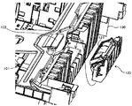
図4は、本体筐体内から引き出されている最中の給紙カセット100を部分的に示す部分拡大図である。図示のように、本プリンタにおいては、分離ローラ121を給紙カセット100に保持させて給紙カセット100とともに本体筺体50に対して着脱するようになっている。これにより、給紙カセット100をローラの回転軸線方向ではなく、同図の左右方向にスライドさせて本体筺体50に対して着脱することを可能にしている。分離ローラ121が給紙カセット100とともに移動することから、給紙カセット100を同図の左右方向に沿った矢印A方向にスライド移動させる際に分離ローラ121が邪魔にならないからである。
FIG. 4 is a partially enlarged view partially showing the
分離ニップに記録シートSが挟まった状態でジャムが発生した場合、作業者は給紙カセット100を図中矢印A方向にスライド移動させて本体筺体50から引き出す。すると、分離ローラ121が給紙カセット100とともに取り出されて分離ニップが無くなるが、ジャムシートは、第1搬送ローラ対41の搬送ニップに挟まれていることから、本体筺体50内に残る。
When a jam occurs with the recording sheet S sandwiched in the separation nip, the operator slides the
給紙カセット100を本体筺体50から引き出したことによって本体筺体50内に発生する空間は、カセット引き出し方向である図中矢印A方向に向けて大きく開口している。作業者は、この開口を通じて、ジャムシートをその面方向から容易に視認することができる。そして、その開口に挿入した両手により、ジャムシートのローラ回転軸線方向の両端部をそれぞれ把持しながら、ジャムシートを搬送ニップから引っ張り出すことができる。この際、ジャムシートの両端部にそれぞれ引っ張り力が付与されることで、ジャムシートの一端部だけが把持される場合に比べて、引っ張り力の集中が抑えられて、ジャムシートの破れが発生し難くなる。
A space generated in the main body casing 50 by pulling out the
よって、本プリンタにおいては、ジャム処理の際におけるジャムシートの破けを抑えることができる。なお、本プリンタにおける給紙カセットの本体筺体50からの引き出し方向(図中矢印A方向)は、図示のように、給紙カセット100をシート収容部105側から分離ローラユニット(分離体収容部)側に移動させる方向である。
Therefore, in this printer, it is possible to suppress tearing of the jam sheet during jam processing. In this printer, the paper feeding cassette is pulled out from the main body housing 50 (in the direction of arrow A in the drawing), as shown in the drawing, the
図5は、給紙カセット100の前側を部分的に示す部分斜視図である。なお、同図においては、便宜上、給紙カセット100の前カバー(引き出し用の把手が付いているカバー)の図示を省略している。図示のように、分離ローラ121は、他のいくつかの部品とともに分離ローラユニット120として構成されていて、給紙カセット100の被装着部に対して一体的に着脱されるようになっている。このように、分離ローラ121をユニット化することで、他機種との部品の共通化を図って低コスト化を実現している。具体的には、本プリンタとは仕様の異なる他機種のカセットにおいても、本プリンタの給紙カセット100と同様の構成を採用している。但し、本プリンタの給紙カセット100とは記録シートSの収容枚数が異なっていることから、カセットの厚みが異なっている。このような仕様の異なる給紙カセットではあるが、分離ローラユニット120については、全く同じ仕様のものを着脱するようになっている。このようにして部品の共通化を図っているのである。
FIG. 5 is a partial perspective view partially showing the front side of the
図6は、分離ローラユニット120を示す分解斜視図である。分離ローラ121の回転軸部材121aには、トルクリミッター122が連結されている。このトルクリミッター122の役割は、既に説明した通りである。トルクリミッター122及び分離ローラ121は、揺動ホルダー123によって保持されている。トルクリミッター122における回転軸部材121aとの連結部とは反対側は、揺動ホルダー123の右側板に固定されている。また、分離ローラ121の回転軸部材aにおける前記連結部とは反端側は、揺動ホルダー123の左側板に回転自在に支持されている。
FIG. 6 is an exploded perspective view showing the
このようにしてトルクリミッター122及び分離ローラ121を保持する揺動ホルダー123は、上カバー126とベースカバー124とからなる収容部材に収容される。具体的には、揺動ホルダー123の右側板及び左側板には、それぞれ同軸線上に並ぶ揺動軸部123aが突設せしめられている。ベースカバー124内に収容された揺動ホルダー123は、それら揺動軸部をベースカバー124の軸穴124aや切り欠き124bに係合させる。これにより、揺動ホルダー123が揺動軸部123aを中心にして揺動するように、ベースカバー124に支持される。
In this way, the swing holder 123 that holds the
上カバー126は、ベースカバー124に対して上方から嵌合する。この状態では、上カバー126に設けられた開口126aと通じて、カバー内部の分離ローラ121の周面が外に露出する(図5参照)。ベースカバー124には、付勢手段としてのコイルバネ125が固定されている。このコイルバネ125により、揺動ホルダー123が揺動軸部123aを中心にして、ベースカバー124側から上カバー126側に向かう方向に付勢されている。分離ローラユニット120を図7に示されるように給紙カセット100に装着していない状態では、上カバー126の裏面に分離ローラ121の周面が突き当たっている。
The
本プリンタにおいては、図1に示される本体筺体50の図中右端の面が前面になっている。また、図中左端の面が背面になっている。また、本体筺体50の同図の紙面に直交する方向における奥端の面が右側面になっている。また、同方向における手前端の面が左側面になっている。つまり、本プリンタでは、本体筺体50内に装着されている給紙カセット100をプリンタの前方に向けて引き出すようになっている。また、給紙カセット100をプリンタの後方に向けて押し込んで本体筐体50内に装着するようになっている。以下、着脱方向に沿ってプリンタの後側から前側に向かう方向を単に前方という。また、その正反対の方向を単に後方という。
In this printer, the rightmost surface of the
図7に示されるように、分離ローラユニット120が給紙カセット100の被装着部に装着されると、給紙カセット100の可動底板101の先端に固定された底板バッド102が分離ローラ121の後方近傍に位置する。底板バッド102は、上述したように、給紙カセット100内に収容された記録シートを給送ローラ(35)に向けて押し当てるものである。
As shown in FIG. 7, when the
図8は、本体筐体内に装着された給紙カセット100の分離ローラユニット120と、本体筐体内に固定された給送ローラ35とを部分的に示す部分斜視図である。給紙カセット100が本体筐体に装着される過程で、本体筐体内に固定された給送ローラ35と、給紙カセット100に保持される分離ローラ121とが当接する。具体的には、給送ローラ35に当接する前の分離ローラ121は、分離ローラユニット120の上カバー126の開口(図6の126a)を通じて、自らの周面の一部を上カバー126よりも外に突出させている。この状態で給紙カセット100とともに本体筐体内に押し込まれていく分離ローラ121は、やがて、本体筐体内に固定されている給送ローラ35の周面に突き当たる。給紙カセット100が更に本体筐体内に押し込まれていくと、分離ローラ121が給送ローラ35に押し返される。この押し返しの力により、揺動ホルダー123がコイルバネ125の付勢力に抗して、揺動軸部123aを中心にして上カバー126側からベースカバー124側に向けて公転し始める。これにより、分離ローラ121が揺動軸部123aを中心にして給送ローラ35側から分離ローラ121側に向けて徐々に公転していき、両ローラの当接部も給送ローラ35側から分離ローラ121側に向けて徐々に移動していく。給紙カセット100が正規の装着位置まで押し込まれると、分離ローラ121が上カバー126の裏面から完全に離間した状態になる。
FIG. 8 is a partial perspective view partially showing the
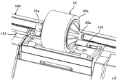
給送ローラ35は、回転軸部材35aと、ローラ状のローラ部35bとを具備している。回転軸部材35aは、ローラ部35bの軸線方向の両端からそれぞれ突出している。また、回転軸部材35aの中心部には、回転駆動軸などを差し込むための中空が設けられている。
The feeding
図9は、本体筺体(図1の50)内の給送ローラセット部を示す拡大構成図である。給送ローラ(図1の35)をセットするための給送ローラセット部は、駆動回転軸38、伸縮軸37などを具備している。駆動回転軸38は、図示しない駆動モータからの駆動力を受けて回転駆動するものである。同図では表されていないが、駆動回転軸38は、円柱状の形状であるが、その先端部だけは断面がアルファベットのDのような形状(以下、D形状という)になっている。図8に示される給送ローラ35において、ローラ部35bの図中両端のうち、図中右側の端部から突出している回転軸部材35aには、図9に示される伸縮軸37が差し込まれる。また、ローラ部35bの図中左側の端部から突出している回転軸部材35aには、図9に示される回転駆動軸38が差し込まれる。
FIG. 9 is an enlarged configuration diagram showing a feeding roller set portion in the main body housing (50 in FIG. 1). The feed roller setting unit for setting the feed roller (35 in FIG. 1) includes a
図8における左側の回転軸部材35aの中空は、その断面がD形状になっている。このため、D形状の回転駆動軸38がピッタリと嵌り込む。そして、この状態で給送ローラ35が回転駆動軸38と一体的に回転駆動する。
The hollow of the left
図9において、伸縮軸37は回転不能に固定されており、図中矢印で示されるように、軸線方向に伸縮することができる。通常は、図示しないバネの付勢力によって伸びきった状態になっているが、作業者が先端部を後端に向けて手で押し込むことにより、縮めることができる。回転駆動軸38の先端と、伸縮軸37の先端との間に、給送ローラ35を入れ込むスペースをつくり出すことができる。作業者は、伸縮軸37を縮めた状態で給送ローラ35を軸線方向に沿って回転駆動軸38に向けて移動させていき、回転駆動軸38のD形状の先端部を給送ローラ35における回転軸部材35aのD形状の中空に入れ込む。その後、伸縮軸37を伸ばすことで、給送ローラ35におけるもう一方の回転軸部材35aに伸縮軸37を差し込む。これにより、図10に示されるように、給送ローラ35のセットが完了する。
In FIG. 9, the
上述したように、図8に示される給送ローラ35における図中左側の回転軸部材35aには、図9に示される伸縮軸37が差し込まれる。その回転軸部材35aにおける中空の断面形状は、図示のように真円形状になっている。そして、図9に示される伸縮軸37の先端部の断面形状も真円形状になっている。伸縮軸37の先端部の形状について、より詳しく説明すると、図11に示されるように、その形状は、先端に存在している先端小径部37aと、それに続く先端大径部37bとを具備する二段円柱形状である。給送ローラ35が給送ローラセット部にセットされた状態では、伸縮軸37は伸びきった状態よりも少し縮んだ状態になっている。伸びきった状態にならないのは、図12に点線で示されるように、伸縮軸37の先端大径部37bが回転軸部材35aの端面に突き当たるからである。この状態では、伸縮軸37の先端大径部37bが回転軸部材35aの端面に強く密着することで、給送ローラ35に対して回転負荷抵抗を付与する。つまり、伸縮軸37は、駆動源による回転駆動力をかけられていない状態で分離ローラ121に当接している給送ローラ35に当接力とは別の回転負荷抵抗を付与する負荷抵抗付与手段として機能している。なお、伸縮軸37の先端大径部37bが給送ローラ35に対して付与する負荷抵抗の向きは、回転軸線方向であるが、先端大径部37bと回転軸部材35aの端面との間では、回転負荷抵抗となって作用する。
As described above, the
給送ローラ35の回転軸部材は、摩擦抵抗の比較的小さなポリアセタール樹脂などから構成されている。給送ローラ35が回転駆動しているときには、給送ローラ35の回転軸部材35aが、回転不能な伸縮軸37の周面上でスリップしながら回転する。このときにも、伸縮軸37は、ある程度の回転負荷抵抗を給送ローラ35に付与しているが、給送ローラ35の駆動トルクに比べれば遙かに小さいものであるので問題ない。
The rotating shaft member of the feeding
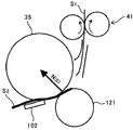
図13は、重送によって分離ニップに挟み込まれた先行シートS1及び後続シートS2のうち、先行シートS1の後端が分離ニップを抜け出して、後続シートS2が給送ローラ35に押し当てられた瞬間の様子を示す模式図である。この瞬間よりも少し前のタイミングで給送ローラ35の回転駆動が停止されていて、先行シートS1は第1搬送ローラ対41の回転駆動力によって搬送されている。このため、図示の状態では、給送ローラ35は完全に回転を停止させている。このとき、分離ローラ121が先行シートS1の厚み分だけ変位して後続シートS2を給送ローラ35表面に押し付ける力に抗して、給送ローラ35の微逆回転を阻止する必要がある。そのために必要な負荷抵抗力は、次のようになる。即ち、給送ローラ35を微逆回転させようとする力は、給送ローラ35と分離ローラ121との間の加圧力N(0)に、給送ローラ35と後続シートS2との間における摩擦係数μをかけた値である。よって、負荷抵抗力をFで表すと、「F>μN(0)」という関係にする必要がある。この負荷抵抗力Fを、伸縮軸37の先端大径部37bによって給送ローラ35の回転軸部材35aに付与するのである。
FIG. 13 shows that among the preceding sheet S 1 and the succeeding sheet S 2 sandwiched in the separation nip by double feeding, the trailing end of the preceding sheet S 1 exits the separation nip, and the succeeding sheet S 2 is pushed by the feeding
図14は、後続シートS2の先端部を分離ローラ121の上に載せた状態の給紙カセット100を本体筺体50にセットした瞬間の様子を示す模式図である。既に述べたように、このとき、次のようにすれば、後続シートS2の折り目の発生を防止することができる。即ち、後続シートS2を介して給送ローラ35に当接している分離ローラ121が給紙カセット100の押し込みによって図中右側から左側に向けて移動するのに伴って、給送ローラ35を正規のシート送り方向とは逆方向に従動回転させるのである。先に示した図13において、給紙ローラ35を微逆回転させようとする力は、分離ローラ121を給送ローラ35に向けて付勢する図示しないコイルバネ(125)の付勢力によって発生するものであり、非常に弱い。これに対し、図14において、分離ローラ121を給紙カセット100とともに押し込んでいく際に給送ローラ35を逆方向に従動回転させようとする力は、作業者のカセット押し込みによって発生するものであり、非常に強い。よって、負荷抵抗力Fを前述の力よりも小さく且つ上述したμN(0)よりも大きくすることで、図13の状態で微逆回転を阻止する一方で、図14の状態で従動回転を許容することが可能になる。
FIG. 14 is a schematic diagram illustrating a state at the moment when the
図14において、給送ローラ35をシート送り方向とは逆方向に従動回転させようとする力は、給送ローラ35と底板パッド102との間に生じる加圧力(給紙加圧力)と、給送ローラ35と後続シートS2との間の摩擦係数μをかけた値である。よって、「F<μN(2)」となる。従って、「μ×N(0)<F<μ×N(2)」という関係にすることで、給送ローラ35の微逆回転に起因する折り目の発生と、給紙カセット100の着脱に起因する折り目の発生とを防止することができる。なお、給送ローラ35の半径をRf、伸縮軸37の先端大径部37bによる負荷トルクをTsで表すと、「μ×N(0)×Rf<Ts<μ×N(2)×Rf」という関係を満たすことになる。仮に、分離圧が1.5[N]、給紙圧が3[N]、μ=0.6とすると、負荷抵抗力Fは0.9〜1.8[N]の範囲になる。
In FIG. 14, the force to rotate the feeding
図15は、第1変形例に係るプリンタの給送ローラセット部を示す模式図である。この第1変形例では、伸縮軸37の代わりに、負荷用トルクリミッター39を負荷抵抗付与手段として機能させている。負荷用トルクリミッター39は、図16に示されるように、回転軸線方向の一端側が給送ローラ35の回転軸部材35aに差し込まれる。そして、負荷用トルクリミッター39の他端側に、回転不能な伸縮軸37が差し込まれる。負荷用トルクリミッター39にかかる回転トルクが閾値を超えると、負荷用トルクリミッター39は回転軸部材35aを回転自在に保持する。これに対し、回転トルクが閾値以下であると、回転軸部材35aを回転不能に保持する。その閾値は、上述したμN(0)よりも大きくなっている。なお、伸縮軸37による負荷抵抗力Fの付与は不要である。
FIG. 15 is a schematic diagram illustrating a feeding roller set unit of a printer according to a first modification. In this first modified example, instead of the
図17は、第2変形例に係るプリンタの給送ローラセット部を示す模式図である。この第2変形例では、伸縮軸37の代わりに、ブレーキ機構を負荷抵抗付与手段として機能させている。このブレーキ機構は、給送ローラ35の回転軸部材35aの周面に対向配設されたブレーキパッド62、これを同周面に向けて付勢するブレーキバネ61、ブレーキパッド62をブレーキバネ61の付勢力に抗して押し返す解除ソレノイド63などから構成される。
FIG. 17 is a schematic diagram illustrating a feeding roller set unit of a printer according to a second modification. In this second modification, the brake mechanism is made to function as a load resistance applying means instead of the
解除ソレノイド63が励磁されている状態では、解除ソレノイド63の軸が図18に示されるように縮んでブレーキパッド62が回転軸部材35aの周面に押し当てられて給送ローラ35にブレーキをかける。これに対し、解除ソレノイド63が励磁されていない状態では、解除ソレノイド63の軸が図17に示されるように伸びてブレーキパッド62が回転軸部材35aの周面から離間する。これによってブレーキが解除される。
In a state where the
ブレーキによって阻止する必要があるのは、プリントジョブの際に発生する給送ローラ35の微逆回転である。この微逆回転は、プリントジョブ中であって、且つ給送ローラ35を回転駆動していない期間に発生する。そこで、図示しない制御部は、前述の期間だけ、解除ソレノイド63を励磁してブレーキをかける。その他の期間では、解除ソレノイド63の励磁をやめてブレーキを解除する。これにより、給送ローラ35を回転駆動しているときには、ブレーキを解除することから、回転駆動中にブレーキをかけることによる無駄なエネルギー消費や部品消耗を回避することができる。なお、かかる構成においては、解除ソレノイド63及び制御部の組み合わせが、負荷抵抗解除手段として機能している。
What needs to be prevented by the brake is a slight reverse rotation of the
以上に説明したものは一例であり、本発明は、次の態様毎に特有の効果を奏する。
[態様A]
本体筺体(例えば本体筺体50)と、自らの内部に記録シートを収容し且つ前記本体筺体に対して着脱可能なシート収容手段(例えば給紙カセット100)と、記録シートに画像を形成する画像形成手段(例えば感光体1やその周囲の装置)と、回転駆動される給送回転体(例えば給送ローラ35)と、互いに重なり合った複数の記録シートから1枚の記録シートを分離するために前記給送回転体に当接して分離ニップを形成しながら従動回転する分離回転体(例えば分離ローラ121)と、前記分離ニップに記録シートが1枚だけ進入した場合には、前記分離回転体の従動回転を許容する一方で、前記分離ニップに複数枚の記録シートが進入した場合には、前記分離回転体の従動回転を許容しないように、前記分離回転体の回転挙動を制御する挙動制御手段(例えばトルクリミッター122)とを備え、前記分離ニップに複数枚の記録シートが進入した場合に、前記挙動制御手段で前記分離回転体の回転挙動を制御することで、それら記録シートのうち、前記給送回転体に直接接触している記録シートだけを分離して前記画像形成手段に向けて給送し、且つ、前記本体筺体内に装着されたシート収容手段に収容される記録シートを前記給送回転体に押し当てて、前記シート収容手段内から前記分離ニップに向けての記録シートの送り出しを前記給送回転体によって行うようにした画像形成装置であって、記録シートを収容するシート収容部(例えばシート収容部105)と、これの側方で前記分離体を収容する分離体収容部(例えば分離ローラユニット120)とを前記シート収容手段に設け、前記分離体を前記シート収容手段に保持させて前記シート収容手段とともに前記本体筺体に対して着脱するようにし、且つ、前記シート収容手段をシート収容部側から分離体収容部側に向けて移動させて前記本体筺体内から引き出すようにし、前記分離ニップに複数枚の記録シートが進入した場合には、前記分離回転体の回転を停止させる制御を実施するように前記挙動制御手段を構成し、且つ、駆動源による回転駆動力を付与していない状態の前記給送回転体に、前記分離回転体との当接力とは別の回転負荷抵抗を付与する負荷抵抗付与手段(例えば伸縮軸37)を設けたことを特徴とするものである。
What has been described above is merely an example, and the present invention has a specific effect for each of the following modes.
[Aspect A]
Main body housing (for example, main body housing 50), sheet storage means (for example, paper feed cassette 100) that stores a recording sheet in its own body and is detachable from the main body housing, and image formation that forms an image on the recording sheet In order to separate one recording sheet from a plurality of recording sheets that overlap each other, such as means (for example, the
かかる構成においては、シート収容手段からの記録シートの送り出しを給送体によって行うことで、シート収容手段のピックアップローラを省略することが可能である。また、記録シートが1枚だけ分離ニップに進入して分離回転体に比較的高い回転トルクが付与されている場合には、トルクリミッター等の挙動制御手段により、分離回転体を従動回転させることで、記録シートの給送を助ける。この一方で、重送が発生したことによって分離回転体にかかる回転トルクが比較的低くなった場合には、挙動制御手段により、分離回転体の回転を阻止する。この阻止により、分離回転体が従動回転しているときに比べて大きな搬送抵抗を分離ニップ内の記録シートに付与することで、複数の記録シートのうち、給送回転体に直接接触している記録シートだけを給送し、他の記録シートを分離ニップ内に留める。これにより、分離回転体を逆回転駆動することなく記録シートを分離することで、分離回転体に駆動を伝達する駆動伝達手段を省略する。これらの結果、分離回転体に駆動を伝達する駆動伝達手段やピックアップローラを省略して低コスト化を図ることができる。 In such a configuration, the pickup roller of the sheet storage unit can be omitted by feeding the recording sheet from the sheet storage unit by the feeding body. When only one recording sheet enters the separation nip and a relatively high rotational torque is applied to the separation rotator, the separation rotator is driven to rotate by a behavior control means such as a torque limiter. , Help the recording sheet feeding. On the other hand, when the rotational torque applied to the separation rotator becomes relatively low due to the occurrence of double feed, the behavior control means prevents the separation rotator from rotating. By preventing the separation rotating body from being driven and rotated by this prevention, a large conveyance resistance is imparted to the recording sheet in the separation nip, thereby directly contacting the feeding rotating body among the plurality of recording sheets. Only the recording sheet is fed and the other recording sheet is kept in the separation nip. Thus, the drive transmission means for transmitting the drive to the separation rotator is omitted by separating the recording sheet without driving the separation rotator in the reverse direction. As a result, it is possible to reduce the cost by omitting the drive transmission means and the pickup roller for transmitting the drive to the separation rotator.
また、態様Aにおいては、分離体をシート収容手段とともに本体筺体に着脱するようにしたことで、先に図20に示した構成とは異なり、分離体とシート収容手段との位置関係を気にすることなく、シート収容手段の引き出し方向を設計することが可能になる。そして、その引き出し方向として、シート収容手段をシート収容部側から分離体収容部側に向けて移動させる方向を採用している。この方向にシート収容手段を引き出すと、引き出し後に本体筺体内に発生する空間の開口は、本体筺体における複数の側板のうち、次の側板に形成される。即ち、例えば図20の本体筺体50における図中右側の側板のように、分離ニップの近傍で引き出し方向と直交する面方向に延在している側板である。このような側板に形成される開口は、本体筺体内に残されたジャムシートの面に対向する。このとき、分離体がシート収容手段とともに引き出されて分離ニップが解放されているが、ジャムシートは給送体よりもシート搬送方向の下流側に配設された搬送ローラ対などの搬送手段に拘束されていることから、本体筺体の中に残っているのである。そして、そのジャムシートの面に対向している前述の開口は、ジャムシートにおける搬送方向と直交する方向の一端部及び他端部の両方を外部に向けて露出させている。作業者は、その開口に挿入した一方の手でジャムシートの一端部を把持するとともに、他方の手でジャムシートの他端部を把持し、それぞれの手でジャムシートを搬送手段から引っ張りながら本体筺体の外に引き出す。この際、ジャムシートの両端部にそれぞれ引っ張り力が付与されることで、ジャムシートの一端部だけしか把持することができない場合に比べて、引っ張り力の集中を抑えて、ジャムシートの破れの発生を抑えることができる。
Further, in the aspect A, since the separator is attached to and detached from the main body housing together with the sheet storage means, unlike the configuration shown in FIG. 20, the positional relationship between the separator and the sheet storage means is concerned. It is possible to design the pull-out direction of the sheet storage means without doing so. And the direction which moves a sheet | seat accommodating means from the sheet | seat accommodating part side toward the separation body accommodating part side is employ | adopted as the drawer | drawing-out direction. When the sheet storage means is pulled out in this direction, the opening of the space generated in the main body casing after the pulling out is formed in the next side plate among the plurality of side plates in the main body casing. That is, for example, the side plate extending in the surface direction perpendicular to the pulling direction in the vicinity of the separation nip, like the right side plate in the
また、態様Aにおいては、給送回転体の回転駆動が停止された後、分離ニップよりも下流側の搬送手段に自らの先端部を進入させた状態で分離ニップから引き出されている先行シートの後端が分離ニップを抜け出る。そして、分離回転体が先行シートの厚み分だけ変位して後続シートを給送回転体に押し当てるときに、負荷抵抗付与手段が給送回転体に対して回転負荷抵抗を付与している。この回転負荷抵抗により、給送回転体の微逆回転が防止されることから、給送回転体にワンウェイクラッチを設けることなく、給送回転体の微逆回転を防止して、後続シートの折り目の発生を抑えることができる。 Further, in the aspect A, after the rotation driving of the feeding rotating body is stopped, the leading sheet pulled out from the separation nip in a state where the leading end of the feeding rotation body enters the conveying means downstream of the separation nip. The rear end exits the separation nip. Then, when the separation rotator is displaced by the thickness of the preceding sheet and presses the succeeding sheet against the feeding rotator, the load resistance applying means applies a rotational load resistance to the feeding rotator. This rotational load resistance prevents the feed rotating body from rotating in the reverse direction, so that the feed rotating body is prevented from being rotated in the reverse direction without providing a one-way clutch on the feeding rotating body. Can be suppressed.
[態様B]
態様Bは、態様Aにおいて、前記給送回転体の回転軸部材に自らの押し当て部材(例えば先端大径部37b)を押し当てることで前記給送回転体に回転負荷抵抗を付与するように、前記負荷抵抗付与手段を構成したことを特徴とするものである。かかる構成では、単に押し当て部材を回転軸部材に常時押し当てるという簡単な構成でも、回転駆動力を付与していない状態の給送回転体に回転負荷抵抗を付与することができる。
[Aspect B]
Aspect B provides a rotational load resistance to the feeding rotating body in aspect A by pressing its own pressing member (for example, the tip
[態様C]
態様Cは、態様Bにおいて、前記押し当て部材を前記給送回転体の回転軸部材の一端面に押し当てるように、前記負荷抵抗付与手段を構成したことを特徴とするものである。かかる構成では、例えば伸縮軸37のように、給送回転体の回転軸部材を保持する手段を、負荷抵抗付与手段として機能させることができる。
[Aspect C]
Aspect C is characterized in that, in aspect B, the load resistance applying means is configured to press the pressing member against one end surface of the rotating shaft member of the feeding rotating body. In such a configuration, for example, a means for holding the rotating shaft member of the feeding rotating body such as the
[態様D]
態様Dは、態様Cにおいて、前記給送回転体の回転軸線方向の一端側における回転軸部材である一端側回転軸部材(例えば図8における左側の回転軸部材35a)に係合した状態で前記回転軸部材と同じ軸線上で回転駆動することで前記給送回転体に回転駆動力を付与する回転駆動軸(例えば回転駆動軸38)を設けるとともに、前記給送回転体の回転軸線方向にスライド移動可能に構成され、且つ前記給送回転体の回転軸線方向の他端側における回転軸部材である他端側軸部材(例えば図8における右側の回転軸部材35a)に係合して前記他端側軸部材を回転自在に保持する保持体(例えば伸縮軸37)と、前記保持体を前記回転軸線方向に沿って前記他端側軸部材に向けて付勢する付勢手段(例えば伸縮軸37内のバネ)とを前記負荷抵抗付与手段に設け、前記付勢手段による付勢力で前記保持体を前記給送回転体の前記他端側軸部材の端面に押し当てることで、前記保持体を前記押し当て部材として機能させたことを特徴とするものである。かかる構成では、保持体を押し当て部材として兼用することができる。
[Aspect D]
Aspect D is the aspect C in the state in which it is engaged with one end side rotating shaft member (for example, the left
[態様E]
態様Eは、態様Bにおいて、前記給送回転体の回転軸部材に閾値を超える回転トルクが発生した場合だけ前記給送回転体の回転を許容するトルクリミッター(例えば負荷用トルクリミッター39)を、前記負荷抵抗付与手段として用いたことを特徴とするものである。かかる構成では、市販の安価なトルクリミッターを負荷抵抗手段として用いることができる。
[Aspect E]
Aspect E provides a torque limiter (for example, a load torque limiter 39) that allows rotation of the feed rotating body only when a rotational torque exceeding a threshold value is generated in the rotating shaft member of the feed rotating body in aspect B. It is used as the load resistance applying means. In such a configuration, a commercially available inexpensive torque limiter can be used as the load resistance means.
[態様F]
態様Fは、態様B又はCにおいて、前記負荷抵抗付与手段による回転負荷抵抗の付与を解除する負荷抵抗解除手段(例えば解除ソレノイド63及び制御部)を設けたことを特徴とするものである。かかる構成では、実施形態で説明したように、給送回転体の回転駆動中にブレーキをかけることによる無駄なエネルギー消費や部品消耗を回避することができる。
[Aspect F]
Aspect F is characterized in that, in aspect B or C, load resistance releasing means (for example,
1:感光体(画像形成手段の一部)
2:クリーニングブレード(画像形成手段の一部)
3:回収スクリュウ(画像形成手段の一部)
4:帯電ローラ(画像形成手段の一部)
7:潜像書込装置(画像形成手段の一部)
8:現像装置(画像形成手段の一部)
9:トナーカートリッジ(画像形成手段の一部)
10:転写ローラ(画像形成手段の一部)
35:給送ローラ(給送回転体)
35a:ローラ部
35b:回転軸部材
37:伸縮軸(負荷抵抗付与手段、保持体)
37b:先端大径部(押し当て部材)
38:回転駆動軸
39:負荷用トルクリミッター(負荷抵抗付与手段)
50:本体筺体
63:解除ソレノイド(負荷抵抗解除手段の一部)
100:給紙カセット(シート収容手段)
101:可動底板(押し当て手段の一部)
102:底板パッド(押し当て手段の一部)
103:底板バネ(押し当て手段の一部)
105:シート収容部
120:分離ローラユニット
121:分離ローラ(分離回転体体)
122:トルクリミッター(挙動制御手段)
123:上カバー(分離体収容部の一部)
124:ベースカバー(分離体収容部の一部)
S:記録シート
1: Photoconductor (part of image forming means)
2: Cleaning blade (part of image forming means)
3: Collection screw (part of image forming means)
4: Charging roller (part of image forming means)
7: Latent image writing device (part of image forming means)
8: Developing device (part of image forming means)
9: Toner cartridge (part of image forming means)
10: Transfer roller (part of image forming means)
35: Feeding roller (feeding rotating body)
35a:
37b: Large diameter portion at the tip (pressing member)
38: Rotation drive shaft 39: Load torque limiter (load resistance applying means)
50: Main body housing 63: Release solenoid (part of load resistance release means)
100: Paper feed cassette (sheet storage means)
101: Movable bottom plate (part of pressing means)
102: Bottom plate pad (part of pressing means)
103: Bottom leaf spring (part of pressing means)
105: Sheet storage unit 120: Separation roller unit 121: Separation roller (separation rotating body)
122: Torque limiter (behavior control means)
123: Upper cover (part of the separator housing part)
124: Base cover (a part of the separator housing part)
S: Recording sheet
Claims (6)
記録シートを収容するシート収容部と、これの側方で前記分離回転体を収容する分離回転体収容部とを前記シート収容手段に設け、前記分離回転体を前記シート収容手段に保持させて前記シート収容手段とともに前記本体筺体に対して着脱するようにし、
且つ、前記シート収容手段をシート収容部側から分離回転体収容部側に向けて移動させて前記本体筺体内から引き出すようにし、
前記分離ニップに複数枚の記録シートが進入した場合には、前記分離回転体の回転を停止させる制御を実施するように前記挙動制御手段を構成し、
且つ、駆動源による回転駆動力を付与していない状態の前記給送回転体に、前記分離回転体との当接力とは別の回転負荷抵抗であり、且つ前記給送回転体と前記分離回転体との加圧によって前記給送回転体を逆回転させようとする力に抗して前記給送回転体の逆回転を阻止する大きさの回転負荷抵抗を付与する負荷抵抗付与手段を設けたことを特徴とする画像形成装置。 A main body housing, a sheet housing means for housing the recording sheet therein and detachable from the main body housing, an image forming means for forming an image on the recording sheet, and a feeding rotating body that is driven to rotate. In order to separate one recording sheet from a plurality of overlapping recording sheets, a separation rotating body that is driven to rotate while being in contact with the feeding rotation body to form a separation nip, and one recording sheet in the separation nip In the case of only entering, the driven rotation of the separation rotator is allowed, while when a plurality of recording sheets enter the separation nip, the driven rotation of the separation rotator is not allowed. A behavior control means for controlling the rotational behavior of the separation rotator, and the behavior control means controls the rotational behavior of the separation rotator when a plurality of recording sheets enter the separation nip. Of the recording sheets, only the recording sheet that is in direct contact with the feeding rotating body is separated and fed toward the image forming means, and the sheet accommodating means mounted in the main body casing An image forming apparatus in which a recording sheet to be stored is pressed against the feeding rotator and the recording sheet is sent out from the sheet storing means toward the separation nip by the feeding rotator. ,
A sheet storage portion for storing the recording sheet and a separation rotation body storage portion for storing the separation rotation body on the side of the recording sheet are provided in the sheet storage means, and the separation rotation body is held by the sheet storage means to It is made to attach and detach with respect to the above-mentioned main body frame with a sheet storing means,
And, the sheet storage means is moved from the sheet storage part side toward the separation rotating body storage part side so as to be pulled out from the main body casing,
When a plurality of recording sheets enter the separation nip, the behavior control means is configured to perform control to stop the rotation of the separation rotating body,
In addition, the feeding rotating body in a state where no rotational driving force is applied by a driving source is a rotational load resistance different from the contact force with the separating rotating body, and the feeding rotating body and the separated rotation There is provided load resistance applying means for applying a rotational load resistance of a magnitude that prevents reverse rotation of the feeding rotating body against a force to reversely rotate the feeding rotating body by pressurization with the body . An image forming apparatus.
前記給送回転体の回転軸部材に自らの押し当て部材を押し当てることで前記給送回転体に回転負荷抵抗を付与するように、前記負荷抵抗付与手段を構成したことを特徴とする画像形成装置。 The image forming apparatus according to claim 1.
The image forming apparatus is characterized in that the load resistance applying means is configured to apply a rotational load resistance to the feeding rotating body by pressing the pressing member against a rotating shaft member of the feeding rotating body. apparatus.
前記押し当て部材を前記給送回転体の回転軸部材の一端面に押し当てるように、前記負荷抵抗付与手段を構成したことを特徴とする画像形成装置。 The image forming apparatus according to claim 2.
The image forming apparatus according to claim 1, wherein the load resistance applying unit is configured to press the pressing member against one end surface of the rotating shaft member of the feeding rotating body.
前記給送回転体の回転軸線方向の一端側における回転軸部材である一端側回転軸部材に係合した状態で前記回転軸部材と同じ軸線上で回転駆動することで前記給送回転体に回転駆動力を付与する回転駆動軸を設けるとともに、
前記給送回転体の回転軸線方向にスライド移動可能に構成され、且つ前記給送回転体の回転軸線方向の他端側における回転軸部材である他端側軸部材に係合して前記他端側軸部材を回転自在に保持する保持体と、前記保持体を前記回転軸線方向に沿って前記他端側軸部材に向けて付勢する付勢手段とを前記負荷抵抗付与手段に設け、
前記付勢手段による付勢力で前記保持体を前記給送回転体の前記他端側軸部材の端面に押し当てることで、前記保持体を前記押し当て部材として機能させたことを特徴とする画像形成装置。 The image forming apparatus according to claim 3.
The feed rotator is rotated by being driven to rotate on the same axis as the rotary shaft member while being engaged with the rotary shaft member which is a rotary shaft member on one end side in the rotation axis direction of the feed rotator. While providing a rotational drive shaft that applies driving force,
The other end is configured to be slidable in the rotation axis direction of the feeding rotating body, and is engaged with the other end side shaft member which is a rotating shaft member on the other end side in the rotation axis direction of the feeding rotating body. A holding body that rotatably holds the side shaft member, and a biasing means that biases the holding body toward the other end side shaft member along the rotation axis direction are provided in the load resistance applying means,
The image is characterized in that the holding body functions as the pressing member by pressing the holding body against the end surface of the other end side shaft member of the feeding rotating body with the urging force of the urging means. Forming equipment.
前記給送回転体の回転軸部材に閾値を超える回転トルクが発生した場合だけ前記給送回転体の回転を許容するトルクリミッターを、前記負荷抵抗付与手段として用いたことを特徴とする画像形成装置。 The image forming apparatus according to claim 2.
An image forming apparatus characterized in that a torque limiter that allows rotation of the feeding rotating body only when a rotational torque exceeding a threshold value is generated on a rotating shaft member of the feeding rotating body is used as the load resistance applying unit. .
前記負荷抵抗付与手段による回転負荷抵抗の付与を解除する負荷抵抗解除手段を設けたことを特徴とする画像形成装置。 The image forming apparatus according to claim 2 or 3,
An image forming apparatus comprising load resistance releasing means for releasing the application of rotational load resistance by the load resistance applying means.
Priority Applications (3)
| Application Number | Priority Date | Filing Date | Title |
|---|---|---|---|
| JP2013232992A JP6245512B2 (en) | 2013-11-11 | 2013-11-11 | Image forming apparatus |
| US14/536,955 US9568879B2 (en) | 2013-11-11 | 2014-11-10 | Image forming apparatus |
| US15/397,131 US9869959B2 (en) | 2013-11-11 | 2017-01-03 | Image forming apparatus |
Applications Claiming Priority (1)
| Application Number | Priority Date | Filing Date | Title |
|---|---|---|---|
| JP2013232992A JP6245512B2 (en) | 2013-11-11 | 2013-11-11 | Image forming apparatus |
Publications (3)
| Publication Number | Publication Date |
|---|---|
| JP2015093746A JP2015093746A (en) | 2015-05-18 |
| JP2015093746A5 JP2015093746A5 (en) | 2017-01-12 |
| JP6245512B2 true JP6245512B2 (en) | 2017-12-13 |
Family
ID=53043918
Family Applications (1)
| Application Number | Title | Priority Date | Filing Date |
|---|---|---|---|
| JP2013232992A Expired - Fee Related JP6245512B2 (en) | 2013-11-11 | 2013-11-11 | Image forming apparatus |
Country Status (2)
| Country | Link |
|---|---|
| US (2) | US9568879B2 (en) |
| JP (1) | JP6245512B2 (en) |
Families Citing this family (17)
| Publication number | Priority date | Publication date | Assignee | Title |
|---|---|---|---|---|
| CN107074469B (en) | 2014-10-24 | 2018-09-04 | 株式会社理光 | Image forming apparatus and dustproof cover |
| US9856099B2 (en) | 2015-05-15 | 2018-01-02 | Ricoh Company, Ltd. | Sheet feeder and image forming apparatus incorporating the sheet feeder |
| JP6848253B2 (en) * | 2016-08-08 | 2021-03-24 | セイコーエプソン株式会社 | Feeding device and image reading device |
| US9757965B1 (en) | 2016-10-14 | 2017-09-12 | Hewlett-Packard Development Company, L.P. | Printing device performance analysis |
| JP6819929B2 (en) | 2016-11-08 | 2021-01-27 | 株式会社リコー | Sheet feeding device, feeding tray, and image forming device |
| US10486922B2 (en) * | 2016-11-09 | 2019-11-26 | Ricoh Company, Ltd. | Sheet feeding device and image forming apparatus incorporating the sheet feeding device |
| JP6922504B2 (en) * | 2016-11-09 | 2021-08-18 | 株式会社リコー | Feeding device and image forming device |
| JP7022372B2 (en) | 2017-12-25 | 2022-02-18 | 株式会社リコー | Seat end position regulating member, seat mounting device, seat feeding device and image forming device |
| JP7137788B2 (en) | 2018-09-27 | 2022-09-15 | 株式会社リコー | Drive transmission device, sheet conveying device and image forming device |
| JP7274859B2 (en) * | 2018-12-20 | 2023-05-17 | 株式会社Pfu | MEDIUM CONVEYING DEVICE, CONTROL METHOD AND CONTROL PROGRAM |
| JP7363276B2 (en) | 2019-09-25 | 2023-10-18 | 沖電気工業株式会社 | Media transport device |
| JP7365579B2 (en) | 2019-11-22 | 2023-10-20 | 株式会社リコー | Sheet storage device and image forming device |
| JP7442765B2 (en) | 2020-03-11 | 2024-03-05 | 株式会社リコー | image forming device |
| CN112607457B (en) * | 2020-12-21 | 2022-11-22 | 泉州铕之易工程管理有限公司 | Marketing is with propaganda list granting device |
| JP2023047839A (en) * | 2021-09-27 | 2023-04-06 | 京セラドキュメントソリューションズ株式会社 | Image forming apparatus |
| JP2023095174A (en) | 2021-12-24 | 2023-07-06 | 株式会社リコー | Conveyance mechanism and image forming device |
| JP2023131521A (en) | 2022-03-09 | 2023-09-22 | 株式会社リコー | Display system and image formation device |
Family Cites Families (28)
| Publication number | Priority date | Publication date | Assignee | Title |
|---|---|---|---|---|
| JPS6152646U (en) * | 1984-09-10 | 1986-04-09 | ||
| JP2902075B2 (en) | 1990-08-10 | 1999-06-07 | キヤノン株式会社 | Automatic paper feeder |
| JP2894531B2 (en) | 1993-04-14 | 1999-05-24 | 東芝テック株式会社 | Automatic paper feeder |
| JPH094332A (en) | 1995-06-19 | 1997-01-07 | Minnesota Mining & Mfg Co <3M> | Article fixture and article fitting method using said fixture |
| JPH1035904A (en) * | 1996-07-24 | 1998-02-10 | Ricoh Co Ltd | Paper feeder |
| JP3368253B2 (en) | 1999-05-13 | 2003-01-20 | キヤノン株式会社 | Sheet feeding device and image processing device provided with the device |
| JP2002080133A (en) | 2000-09-04 | 2002-03-19 | Seiko Epson Corp | Paper feeding device |
| JP4815062B2 (en) | 2001-04-13 | 2011-11-16 | 株式会社リコー | Image forming method and image forming apparatus |
| JP4184641B2 (en) | 2001-04-16 | 2008-11-19 | 株式会社リコー | Paper feeding device and image forming apparatus |
| JP4094332B2 (en) | 2002-04-23 | 2008-06-04 | 丸善製薬株式会社 | Water dispersible or water soluble banaba leaf extract composition |
| JP4612893B2 (en) * | 2005-12-27 | 2011-01-12 | キヤノン株式会社 | Sheet feeding apparatus and image forming apparatus |
| JP4544180B2 (en) * | 2006-03-01 | 2010-09-15 | ブラザー工業株式会社 | Image forming apparatus |
| JP4994811B2 (en) * | 2006-12-04 | 2012-08-08 | キヤノン株式会社 | Torque limiter and sheet feeding device |
| JP2009120293A (en) * | 2007-11-13 | 2009-06-04 | Ricoh Co Ltd | Paper feeding device and image forming device |
| JP5429621B2 (en) | 2009-09-03 | 2014-02-26 | 株式会社リコー | Sheet material feeding apparatus and image forming apparatus provided with the same |
| JP5532392B2 (en) | 2009-09-14 | 2014-06-25 | 株式会社リコー | Sheet material feeding apparatus and image forming apparatus provided with the same |
| JP2011063391A (en) | 2009-09-17 | 2011-03-31 | Ricoh Co Ltd | Sheet material feed device and image forming device having the same |
| JP5471844B2 (en) | 2009-11-25 | 2014-04-16 | 株式会社リコー | Paper feeding device and image forming apparatus |
| JP5532863B2 (en) | 2009-11-27 | 2014-06-25 | 株式会社リコー | Paper feeding device and image forming apparatus |
| JP5605678B2 (en) | 2010-02-22 | 2014-10-15 | 株式会社リコー | Sheet conveying apparatus and image forming apparatus |
| JP5561593B2 (en) | 2010-02-22 | 2014-07-30 | 株式会社リコー | Sheet conveying apparatus and image forming apparatus |
| JP5545543B2 (en) | 2010-09-09 | 2014-07-09 | 株式会社リコー | Sheet conveying apparatus and image forming apparatus |
| JP5691525B2 (en) | 2011-01-05 | 2015-04-01 | 株式会社リコー | Sheet separating and feeding apparatus and image forming apparatus having the same |
| JP5748048B2 (en) | 2011-03-16 | 2015-07-15 | 株式会社リコー | Sheet separating and conveying apparatus and image forming apparatus using the same |
| JP5269152B2 (en) * | 2011-06-24 | 2013-08-21 | キヤノン株式会社 | Sheet feeding apparatus and image forming apparatus |
| JP5842546B2 (en) | 2011-11-04 | 2016-01-13 | 株式会社リコー | Inkjet recording device |
| JP6041099B2 (en) | 2012-12-27 | 2016-12-07 | 株式会社リコー | Paper feeding device and image forming apparatus |
| JP6236789B2 (en) | 2013-01-29 | 2017-11-29 | 株式会社リコー | Paper feeding device and image forming apparatus having the same |
-
2013
- 2013-11-11 JP JP2013232992A patent/JP6245512B2/en not_active Expired - Fee Related
-
2014
- 2014-11-10 US US14/536,955 patent/US9568879B2/en not_active Expired - Fee Related
-
2017
- 2017-01-03 US US15/397,131 patent/US9869959B2/en active Active
Also Published As
| Publication number | Publication date |
|---|---|
| US20150132039A1 (en) | 2015-05-14 |
| JP2015093746A (en) | 2015-05-18 |
| US9869959B2 (en) | 2018-01-16 |
| US20170115618A1 (en) | 2017-04-27 |
| US9568879B2 (en) | 2017-02-14 |
Similar Documents
| Publication | Publication Date | Title |
|---|---|---|
| JP6245512B2 (en) | Image forming apparatus | |
| CN108016905B (en) | Sheet conveying apparatus and image forming apparatus | |
| KR100869976B1 (en) | Image forming apparatus and conveyance device | |
| EP2975463B1 (en) | Image forming apparatus | |
| JP6452031B2 (en) | Image forming apparatus | |
| JP6566337B2 (en) | Image forming apparatus | |
| JP6350894B2 (en) | Image forming apparatus | |
| JP2012046353A (en) | Image forming device | |
| JP2006349702A (en) | Image forming apparatus | |
| JP5775954B2 (en) | Conveying device and image forming apparatus incorporating the conveying device | |
| JP2008058892A (en) | Image forming apparatus | |
| KR20150018202A (en) | Sheet feeding apparatus for image forming apparatus | |
| JP4877202B2 (en) | Sheet conveying apparatus and image forming apparatus | |
| JP2010159142A (en) | Sheet carrying device and image forming device | |
| JP2021060505A (en) | Image forming apparatus | |
| JP2009084021A (en) | Paper feeder and image forming device having the same | |
| JP2006349878A (en) | Image forming apparatus | |
| JP7333009B2 (en) | Sheet conveying device and image forming device | |
| JP2008265914A (en) | Paper feeder and image forming device provided with this | |
| JP2010262188A (en) | Image forming apparatus | |
| JP2007219179A (en) | Image forming apparatus | |
| JP4662170B2 (en) | Sheet conveying apparatus, image forming apparatus, and sheet supply apparatus | |
| CN112782948A (en) | Sheet conveying device and image forming apparatus | |
| JP5661160B2 (en) | Conveying device and image forming apparatus incorporating the conveying device | |
| JP2005324922A (en) | Medium turnover device |
Legal Events
| Date | Code | Title | Description |
|---|---|---|---|
| A621 | Written request for application examination |
Free format text: JAPANESE INTERMEDIATE CODE: A621 Effective date: 20161021 |
|
| A521 | Request for written amendment filed |
Free format text: JAPANESE INTERMEDIATE CODE: A523 Effective date: 20161129 |
|
| A977 | Report on retrieval |
Free format text: JAPANESE INTERMEDIATE CODE: A971007 Effective date: 20170712 |
|
| A131 | Notification of reasons for refusal |
Free format text: JAPANESE INTERMEDIATE CODE: A131 Effective date: 20170721 |
|
| A521 | Request for written amendment filed |
Free format text: JAPANESE INTERMEDIATE CODE: A523 Effective date: 20170914 |
|
| TRDD | Decision of grant or rejection written | ||
| A01 | Written decision to grant a patent or to grant a registration (utility model) |
Free format text: JAPANESE INTERMEDIATE CODE: A01 Effective date: 20171020 |
|
| A61 | First payment of annual fees (during grant procedure) |
Free format text: JAPANESE INTERMEDIATE CODE: A61 Effective date: 20171102 |
|
| R151 | Written notification of patent or utility model registration |
Ref document number: 6245512 Country of ref document: JP Free format text: JAPANESE INTERMEDIATE CODE: R151 |
|
| LAPS | Cancellation because of no payment of annual fees |