JP6244045B2 - Integrated motor driven power electronics system and method with improved efficiency - Google Patents
Integrated motor driven power electronics system and method with improved efficiency Download PDFInfo
- Publication number
- JP6244045B2 JP6244045B2 JP2016573941A JP2016573941A JP6244045B2 JP 6244045 B2 JP6244045 B2 JP 6244045B2 JP 2016573941 A JP2016573941 A JP 2016573941A JP 2016573941 A JP2016573941 A JP 2016573941A JP 6244045 B2 JP6244045 B2 JP 6244045B2
- Authority
- JP
- Japan
- Prior art keywords
- power
- voltage
- output
- converter
- motor
- Prior art date
- Legal status (The legal status is an assumption and is not a legal conclusion. Google has not performed a legal analysis and makes no representation as to the accuracy of the status listed.)
- Active
Links
- 238000000034 method Methods 0.000 title claims description 7
- 230000002457 bidirectional effect Effects 0.000 claims description 91
- 230000001105 regulatory effect Effects 0.000 claims description 13
- 238000006243 chemical reaction Methods 0.000 claims 2
- 230000003213 activating effect Effects 0.000 claims 1
- 238000010586 diagram Methods 0.000 description 30
- 238000004146 energy storage Methods 0.000 description 11
- 230000033228 biological regulation Effects 0.000 description 6
- 230000008859 change Effects 0.000 description 6
- 230000001360 synchronised effect Effects 0.000 description 6
- 230000004044 response Effects 0.000 description 5
- 230000014759 maintenance of location Effects 0.000 description 4
- HBMJWWWQQXIZIP-UHFFFAOYSA-N silicon carbide Chemical compound [Si+]#[C-] HBMJWWWQQXIZIP-UHFFFAOYSA-N 0.000 description 4
- 239000003990 capacitor Substances 0.000 description 3
- 230000001965 increasing effect Effects 0.000 description 3
- 238000013459 approach Methods 0.000 description 2
- 230000002238 attenuated effect Effects 0.000 description 2
- 230000007423 decrease Effects 0.000 description 2
- 238000013461 design Methods 0.000 description 2
- 238000001914 filtration Methods 0.000 description 2
- 230000006870 function Effects 0.000 description 2
- 230000007659 motor function Effects 0.000 description 2
- 238000011084 recovery Methods 0.000 description 2
- 230000001172 regenerating effect Effects 0.000 description 2
- 229910010271 silicon carbide Inorganic materials 0.000 description 2
- 238000012546 transfer Methods 0.000 description 2
- 230000005540 biological transmission Effects 0.000 description 1
- 238000004891 communication Methods 0.000 description 1
- 230000001276 controlling effect Effects 0.000 description 1
- 238000001816 cooling Methods 0.000 description 1
- 230000003247 decreasing effect Effects 0.000 description 1
- 238000001514 detection method Methods 0.000 description 1
- 239000012530 fluid Substances 0.000 description 1
- 230000014509 gene expression Effects 0.000 description 1
- 230000001939 inductive effect Effects 0.000 description 1
- 230000007246 mechanism Effects 0.000 description 1
- 230000003287 optical effect Effects 0.000 description 1
- 230000000737 periodic effect Effects 0.000 description 1
- 230000008569 process Effects 0.000 description 1
- 239000000758 substrate Substances 0.000 description 1
- 238000004804 winding Methods 0.000 description 1
Images


Classifications
-
- H—ELECTRICITY
- H02—GENERATION; CONVERSION OR DISTRIBUTION OF ELECTRIC POWER
- H02P—CONTROL OR REGULATION OF ELECTRIC MOTORS, ELECTRIC GENERATORS OR DYNAMO-ELECTRIC CONVERTERS; CONTROLLING TRANSFORMERS, REACTORS OR CHOKE COILS
- H02P3/00—Arrangements for stopping or slowing electric motors, generators, or dynamo-electric converters
- H02P3/06—Arrangements for stopping or slowing electric motors, generators, or dynamo-electric converters for stopping or slowing an individual dynamo-electric motor or dynamo-electric converter
- H02P3/08—Arrangements for stopping or slowing electric motors, generators, or dynamo-electric converters for stopping or slowing an individual dynamo-electric motor or dynamo-electric converter for stopping or slowing a dc motor
- H02P3/14—Arrangements for stopping or slowing electric motors, generators, or dynamo-electric converters for stopping or slowing an individual dynamo-electric motor or dynamo-electric converter for stopping or slowing a dc motor by regenerative braking
-
- H—ELECTRICITY
- H02—GENERATION; CONVERSION OR DISTRIBUTION OF ELECTRIC POWER
- H02M—APPARATUS FOR CONVERSION BETWEEN AC AND AC, BETWEEN AC AND DC, OR BETWEEN DC AND DC, AND FOR USE WITH MAINS OR SIMILAR POWER SUPPLY SYSTEMS; CONVERSION OF DC OR AC INPUT POWER INTO SURGE OUTPUT POWER; CONTROL OR REGULATION THEREOF
- H02M1/00—Details of apparatus for conversion
- H02M1/14—Arrangements for reducing ripples from dc input or output
- H02M1/15—Arrangements for reducing ripples from dc input or output using active elements
-
- H—ELECTRICITY
- H03—ELECTRONIC CIRCUITRY
- H03H—IMPEDANCE NETWORKS, e.g. RESONANT CIRCUITS; RESONATORS
- H03H11/00—Networks using active elements
- H03H11/46—One-port networks
-
- H—ELECTRICITY
- H02—GENERATION; CONVERSION OR DISTRIBUTION OF ELECTRIC POWER
- H02M—APPARATUS FOR CONVERSION BETWEEN AC AND AC, BETWEEN AC AND DC, OR BETWEEN DC AND DC, AND FOR USE WITH MAINS OR SIMILAR POWER SUPPLY SYSTEMS; CONVERSION OF DC OR AC INPUT POWER INTO SURGE OUTPUT POWER; CONTROL OR REGULATION THEREOF
- H02M1/00—Details of apparatus for conversion
- H02M1/0067—Converter structures employing plural converter units, other than for parallel operation of the units on a single load
- H02M1/007—Plural converter units in cascade
-
- H—ELECTRICITY
- H02—GENERATION; CONVERSION OR DISTRIBUTION OF ELECTRIC POWER
- H02P—CONTROL OR REGULATION OF ELECTRIC MOTORS, ELECTRIC GENERATORS OR DYNAMO-ELECTRIC CONVERTERS; CONTROLLING TRANSFORMERS, REACTORS OR CHOKE COILS
- H02P2201/00—Indexing scheme relating to controlling arrangements characterised by the converter used
- H02P2201/07—DC-DC step-up or step-down converter inserted between the power supply and the inverter supplying the motor, e.g. to control voltage source fluctuations, to vary the motor speed
-
- H—ELECTRICITY
- H02—GENERATION; CONVERSION OR DISTRIBUTION OF ELECTRIC POWER
- H02P—CONTROL OR REGULATION OF ELECTRIC MOTORS, ELECTRIC GENERATORS OR DYNAMO-ELECTRIC CONVERTERS; CONTROLLING TRANSFORMERS, REACTORS OR CHOKE COILS
- H02P2201/00—Indexing scheme relating to controlling arrangements characterised by the converter used
- H02P2201/09—Boost converter, i.e. DC-DC step up converter increasing the voltage between the supply and the inverter driving the motor
Landscapes
- Engineering & Computer Science (AREA)
- Power Engineering (AREA)
- Dc-Dc Converters (AREA)
- Inverter Devices (AREA)
Description
[優先権の主張]
本願は、2014年6月18日付けで出願された米国特許出願第14/307728号に基づく優先権を主張するものである。優先権の基礎となる米国特許出願は、その全文を参照により本願に援用される。
[Priority claim]
This application claims priority from US patent application Ser. No. 14 / 307,728, filed Jun. 18, 2014. The priority US patent application is incorporated herein by reference in its entirety.
[技術分野]
実施形態は、モーター駆動パワーエレクトロニクスに関係がある。いくつかの実施形態は、電子システムのためのモーター駆動パワーエレクトロニクスに関係がある。いくつかの実施形態は、クライオクーラー(cryocooler(s))のためのモーター駆動パワーエレクトロニクスに関係がある。
[Technical field]
Embodiments relate to motor driven power electronics. Some embodiments relate to motor driven power electronics for electronic systems. Some embodiments relate to motor driven power electronics for a cryocooler (s).
通信システム、レーダーシステム、赤外線センサシステム、レーザー追跡システム、又は指向性エネルギシステムのような電子システムは、地上、移動体、空中、船上、又は宇宙船のいずれに置かれようとも、一般的に、電源から電力バスを介して電力を受けるいくつかのサブシステムを備える。あるサブシステムは、電源からリプル電流を引き込むことがある。これは、他のサブシステムに影響を及ぼすことがある。例えば、あるタイプのセンサシステムの場合に、極低温クーラー駆動エレクトロニクスシステムは、電力バスから35から100Hzの間の公称周波数で10アンペア以上のリプル電流を引き込んでよい。しかし、大きなリプル電流引き込みは、バスの安定性を損なうことがあり、且つ、バスを使用する他のエレクトロニクス、特に、低電力センサ信号を管理するもの、の性能を低下させうる。よって、MIL−STD−461のような、伝導性放射EMIを制限する規定が課されている。 Electronic systems such as communication systems, radar systems, infrared sensor systems, laser tracking systems, or directional energy systems, whether placed on the ground, mobile, air, on board, or spacecraft, It includes several subsystems that receive power from a power source via a power bus. Some subsystems may draw ripple current from the power supply. This can affect other subsystems. For example, for certain types of sensor systems, the cryogenic cooler drive electronics system may draw more than 10 amps of ripple current from the power bus at a nominal frequency between 35 and 100 Hz. However, large ripple current draw can impair the stability of the bus and can degrade the performance of other electronics that use the bus, particularly those that manage low power sensor signals. Therefore, regulations are imposed to limit conducted radiated EMI, such as MIL-STD-461.
大きいキャパシタ及びインダクタを有するパッシブフィルタは、電力バス上の電流リプルを低減するために使用されてきた。しかし、低周波フィルタバンド幅のために使用されるそのような大きいキャパシタ及びインダクタのサイズ及び重量は、サイズ及び重量が考慮される要素である用途にとってそれらのアプローチを望ましくないものとする。負荷と並列なシャントレギュレータも使用されてきた。そのようなシャントレギュレータは、軽負荷条件下で負荷電流を引き込み、システムの重負荷条件下でシャント電力を低減して、電源から引き込まれる正味電流をいくらか一定に保つ。このアプローチは、比較的軽い変動負荷についてうまく働くことができるが、電力を浪費する。高い電力で、又は大量のシャントレギュレータについて、シャント負荷の電力散逸は過大になり、正味の総電力引き込みを増大させ且つ電力システムの効率を低下させうる。AC結合型シャントレギュレータも使用されるが、それらも過大な電力散逸を欠点とし、そして、それらはAC結合されていることから、バンド幅制限を欠点とする。 Passive filters with large capacitors and inductors have been used to reduce current ripple on the power bus. However, the size and weight of such large capacitors and inductors used for low frequency filter bandwidths make those approaches undesirable for applications where size and weight are factors. A shunt regulator in parallel with the load has also been used. Such a shunt regulator draws load current under light load conditions and reduces shunt power under heavy load conditions in the system, keeping the net current drawn from the power source somewhat constant. This approach can work well for relatively light variable loads, but wastes power. At high power, or for large shunt regulators, the power dissipation of the shunt load can be excessive, increasing the net total power draw and reducing the efficiency of the power system. AC coupled shunt regulators are also used, but they also suffer from excessive power dissipation, and because they are AC coupled, suffer from bandwidth limitations.
加えて、モーターは、それらの動作サイクルのある部分の間、いくつかの動作条件において電源として働くことができる。従って、モーター駆動エレクトロニクスは、モーターから電力をシンクし且つ電力をモーターへ供給してよい。例えば、いくつかの電気自動車で使用されている回生制動(regenerative breaking)は、回生制動を提供する発電機としてドライブモーターを使用する。制動の量は、モーターから引き込まれる電力に比例する。最大効率のために、制動を提供するためにモーターから引き込まれる電力は、車両バッテリへ戻される。 In addition, the motor can serve as a power source in several operating conditions during some portion of their operating cycle. Thus, the motor drive electronics may sink power from the motor and supply power to the motor. For example, regenerative breaking used in some electric vehicles uses a drive motor as a generator to provide regenerative braking. The amount of braking is proportional to the power drawn from the motor. For maximum efficiency, power drawn from the motor to provide braking is returned to the vehicle battery.
他の例として、上記の極低温クーラーがある。いくつかの極低温クーラーについて、モーターは、動作サイクルのある部分の間、電源として働き、流体からエネルギを吸収し、電力を供給することによって、ポジション制御制動又は温度制御を提供する。極低温クーラーシステムのモーター駆動エレクトロニクスは、従って、モーターへ電力を供給するだけでなく、モーターから電力をシンクする。 Another example is the cryogenic cooler described above. For some cryogenic coolers, the motor provides position controlled braking or temperature control by acting as a power source during certain parts of the operating cycle, absorbing energy from the fluid and supplying power. The motor driven electronics of the cryogenic cooler system thus sinks power from the motor as well as powering the motor.
このように、極低温クーラーシステムでは、モーターに対する双方向の電力フローが存在し、モーター駆動エレクトロニクスは、動作サイクルのある部分の間、エネルギをモーターへ供給し、そして、エネルギをモーターから受ける。従来、極低温クーラーシステムにおいて、いくつかのクライオクーラーモーターから供給される電力は、抵抗器又は他の負荷において単に散逸され、熱に変換されていた。結果として、電気エネルギは、蓄えたり又は何らかのタイプの仕事に変換されたりされず、従って無駄になる。小型コンバータは、極低温クーラー駆動エレクトロニクスにおいて、電力をモーターからシンクし、そして、いつでも電力を供給しているモーターのためのソースへ電力を戻すために使用されてきた。しかし、モーターから電力をシンクするための小型コンバータの使用は、モーターがいつでも電力を供給している極低温クーラーにおいてしか有用でない。 Thus, in a cryogenic cooler system, there is a bidirectional power flow to the motor, and the motor drive electronics supply energy to the motor and receive energy from the motor during certain parts of the operating cycle. In the past, in cryogenic cooler systems, the power supplied from some cryocooler motors was simply dissipated in resistors or other loads and converted to heat. As a result, electrical energy is not stored or converted into some type of work and is therefore wasted. Small converters have been used in cryogenic cooler-driven electronics to sink power from the motor and return power to the source for the motor that is supplying power at any time. However, the use of a small converter to sink power from the motor is only useful in cryogenic coolers where the motor is always supplying power.
よって、電気モーターを駆動し、リプル電流が電力バスへ反射されることを防ぐ必要性が存在する。すなわち、電力バスから引き込まれる入力電流を効率良く制御及び調整して、電力バスへフィードバックされるリプル電流を低減するシステム及び方法に対する一般的な必要性が存在する。加えて、モーターが電力を供給している時間中にモーター電力を入力電源へ効率良く戻す必要性が存在する。また、それらの機能の両方を提供する効率の良いモーター駆動電力システムに対する必要性が存在する。 Thus, there is a need to drive an electric motor and prevent ripple current from being reflected back to the power bus. That is, there is a general need for systems and methods that efficiently control and regulate the input current drawn from the power bus to reduce the ripple current fed back to the power bus. In addition, there is a need to efficiently return motor power to the input power source during the time that the motor is providing power. There is also a need for an efficient motor drive power system that provides both of these functions.
1つ以上の電気モーターを駆動し得る効率の良いモーター駆動電力システムのための装置及び方法であって、負荷電流変動及びリプルが電力バスへ反射されないように、電力バスから引き込まれる入力電流を制御及び調整するものが提供される。加えて、モーター駆動電力システムは、1つ以上のモーターが電力を供給している時間中に入力電源へモーター電力を効率良く戻す。 An apparatus and method for an efficient motor driven power system capable of driving one or more electric motors to control input current drawn from the power bus so that load current fluctuations and ripples are not reflected to the power bus And what to adjust is provided. In addition, the motor drive power system efficiently returns motor power to the input power source during the time that one or more motors are supplying power.
以下の説明及び図面は、具体的な実施形態を、それらを実施することを当業者に可能にするほど十分に表す。他の実施形態は、構造上の、論理上の、電気的な、プロセスの、及び多の変更を組み込んでよい。いくつかの実施形態の部分及び特徴は、他の実施形態のそれらに含まれるか、又は置換されてよい。特許請求の範囲で示される実施形態は、特許請求の範囲の全ての利用可能な均等を包含する。 The following description and drawings sufficiently represent specific embodiments to enable those skilled in the art to practice them. Other embodiments may incorporate structural, logical, electrical, process, and numerous changes. Parts and features of some embodiments may be included or substituted in those of other embodiments. Embodiments set forth in the claims encompass all available equivalents of those claims.
実施形態に従って、モーター駆動パワーエレクトロニクスシステムは、1つ以上のモーターへ電力を供給し、且つ、1つ以上のモーターが電力を供給している場合に入力電源へ電力を戻す。アクティブラインフィルタは、入力バスから引き込まれる入力電流をDCレベルに調整し、よって、電源へフィードバックされるリプル電流を減衰し、そして、出力電圧リプルに応じて入力電流を変調しないように追加の制御回路を含んでよい。 In accordance with embodiments, the motor driven power electronics system provides power to one or more motors and returns power to the input power source when one or more motors are providing power. The active line filter adjusts the input current drawn from the input bus to a DC level, thus attenuating the ripple current fed back to the power supply and providing additional control to not modulate the input current in response to the output voltage ripple A circuit may be included.
次の米国特許は、参照により本願に援用される:米国特許第7038435号、米国特許第7019503号、及び米国特許第7141940号。次の特許出願は、参照により本願に援用される:2013年4月2日付けで出願された米国特許出願第13/855298。 The following US patents are hereby incorporated by reference: US Pat. No. 7,038,435, US Pat. No. 7,019,503, and US Pat. No. 7,141,940. The following patent application is hereby incorporated by reference: US patent application Ser. No. 13 / 855,298 filed Apr. 2, 2013.
本願において、実施形態は、電力をモーターへ供給し且つモーターからの電力を再利用すること、例えば、極低温クーラーモーター、に関連して説明され得る。なお、当業者であれば、本願で記載される実施形態は他の実施形態にも適用可能であってよく、従って、そのような説明に限定する意図はないことを認識するだろう。然るに、他の形態及び/又は表現は、本願で記載される実施形態の適用範囲から逸脱することなしに実施されてよい。 In this application, embodiments may be described in the context of supplying power to a motor and reusing power from the motor, for example, a cryogenic cooler motor. One skilled in the art will recognize that the embodiments described herein may be applicable to other embodiments and are therefore not intended to be limited to such descriptions. However, other forms and / or expressions may be implemented without departing from the scope of the embodiments described herein.
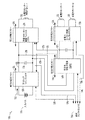
図1は、実施形態に従うモーター駆動パワーエレクトロニクスシステム100を表す。図1において、入力バス110はアクティブラインフィルタ120へ結合されている。アクティブラインフィルタ120は、入力バス110から引き込まれる調整されたDC入力電流112を供給して、入力バス110へ反射されるリプル電流を低減する。アクティブラインフィルタ120は、入力バス110からエネルギ保持キャパシタンス124への単方向電力フロー121を供給し、且つ、調整された出力電圧122をエネルギ保持キャパシタンス124にわたって供給する。
FIG. 1 illustrates a motor driven
エネルギ保持キャパシタンス124は、アクティブラインフィルタ120の出力部にある高電力モーター駆動エレクトロニクス130及び双方向LVPS140のための局所入力電源として働く。高電力モーター駆動エレクトロニクス130によって引き込まれる負荷電流に双方向LVPS140によって引き込まれる負荷電流を足したものがアクティブラインフィルタ120によって供給される電流に満たない間は、エネルギ保持キャパシタンス124は、アクティブラインフィルタ120によって供給される電流と、高電力モーター駆動エレクトロニクス130によって引き込まれる負荷電流に双方向LVPS140によって引き込まれる負荷電流を足したものとの間の差によって再充電される。高電力モーター駆動エレクトロニクス130によって引き込まれる負荷電流に双方向LVPS140によって引き込まれる負荷電流を足したものがアクティブラインフィルタ120によって供給される電流よりも大きい間は、エネルギ保持キャパシタンス124は、高電力モーター駆動エレクトロニクス130によって引き込まれる負荷電流に双方向LVPS140によって引き込まれる負荷電流を足したものと、アクティブラインフィルタ120によって供給される電流との間の電流の差を供給する。
The
実施形態に従って、アクティブラインフィルタ120は、極めて低いバンド幅制御ループを備えた高スイッチング周波数連続電流ブーストコンバータであってよい。アクティブラインフィルタ120はまた、多数の他のスイッチングコンバータトポロジのいずれを利用してもよく、絶縁又は非絶縁出力を供給する。アクティブラインフィルタ120は、入力バス110から引き込まれる調整された入力電流112に極めて遅い出力電圧調整ループを提供するよう電流モード制御を用いて作動してよい。アクティブラインフィルタ120は、出力電圧フィードフォワードによるピーク電流モード制御、平均電流モード制御、又は調整された出力電圧122における出力電圧リプルに応じて入力電流112を変調しないように変形された平均電流モード制御を利用してよい。アクティブラインフィルタ120は、代替的に、電圧モード制御又はヒステリシス電流制御を用いて作動してよい。アクティブラインフィルタ120はまた、入力電圧トランジェントに対して及び出力負荷トランジェントに対して非常に速い応答を提供して、エネルギ保持キャパシタンス124において出力電圧122の調整を保つよう、入力電圧フィードフォワード信号(図示せず。)及び出力負荷フィードフォワード信号(図示せず。)を利用してよい。入力バス110から引き込まれる入力電流をDCレベルに調整することによって、アクティブラインフィルタ120は、エネルギ保持キャパシタンス124から高電力モーター駆動エレクトロニクス130によって引き込まれる負荷電流と比べて、有意に減衰された電流リプルをDC電流引き込みにもたらす。実施形態に従って、アクティブラインフィルタ120は、パッシブフィルタリングと比較して有意に低減されたサイズ及び重量において高スイッチング周波数で高い効率を保つよう、炭化ケイ素出力整流器を用いて実装されてよい。アクティブラインフィルタ120は、構成可能インターフェイス126を用いて、制御エレクトロニクス160からの信号によって制御されてよく、あるいは、制御エレクトロニクス160へステータス報告を供給してよく、あるいは、その両方を行ってよい。
According to embodiments, the
高電力モーター駆動エレクトロニクス130は、エネルギ保持キャパシタンス124へ結合されており、モーター132としてここでは示されている1つ以上の高電力モーターへ、それらのモーターが電力をシンクしている場合に駆動電力を供給し、高電力モーター132が電力を供給している場合には、高電力モーター132からエネルギ保持キャパシタンス124へ電力を戻す。然るに、高電力モーター駆動エレクトロニクス130は、双方向の電力フロー134を供給する。高電力モーター駆動エレクトロニクス130は、相当のリプル電流を引き込んでよい。高電力モーター駆動エレクトロニクス130は、エネルギ保持キャパシタンス124から絶縁されている、又はエネルギ保持キャパシタンス124から絶縁されていない高電力モーター132へ電力を供給してよい。高電力モーター駆動エレクトロニクス130は、構成可能インターフェイス136を用いて、制御エレクトロニクス160からの信号によって制御されてよく、あるいは、制御エレクトロニクス160へステータス報告を供給してよく、あるいは、その両方を行ってよい。
The high power motor drive electronics 130 are coupled to the
双方向低電圧電源(LVPS;low voltage power supply)140は、エネルギ保持キャパシタンス124へ結合されており、エネルギ保持キャパシタンス124に蓄えられているエネルギによって給電される。双方向LVPSは、双方向電力155を低電力モーター駆動エレクトロニクス150へ供給してよく、バイアス電力125をアクティブラインフィルタ120へ供給してよく、バイアス電力135を高電力モーター駆動エレクトロニクス130へ供給してよく、そして、低電力モーター駆動エレクトロニクス150からエネルギ保持キャパシタンス124へ電力155を戻してよい。然るに、双方向LVPS140は、双方向電力フロー144を供給する。実施形態に従って、双方向LVPS140は、2つの電力コンバータ(図1に図示せず。)を使用してよく、第1の電力コンバータは、電力155を低電力駆動エレクトロニクス150へ供給してよく、バイアス電力125をアクティブラインフィルタ120へ供給してよく、バイアス電力135を高電力モーター駆動エレクトロニクス130へ供給してよく、第2の電力コンバータは、電力155を低電力駆動エレクトロニクス150からシンクし、電力をエネルギ保持キャパシタンス124へ戻してよい。双方向LVPS140は、双方向電力155を低電力モーター駆動エレクトロニクス150へ、電力125をアクティブラインフィルタ120へ、そして、電力135を、エネルギ保持キャパシタンス124から絶縁されている、又はエネルギ保持キャパシタンス124から絶縁されていない高電力モーター駆動エレクトロニクス130へ供給してよい。双方向LVPS140は、構成可能インターフェイス146を用いて、制御エレクトロニクス160からの信号によって制御されてよく、あるいは、制御エレクトロニクス160へステータス報告を供給してよく、あるいは、その両方を行ってよい。
A bidirectional low voltage power supply (LVPS) 140 is coupled to the
双方向LVPS140は、代替的に、2つよりも多い電力コンバータを使用してよく(図1に図示せず。)、例えば、第1の電力コンバータは、電力155を低電力駆動エレクトロニクス150へ供給してよく、第2のコンバータは、バイアス電力125をアクティブラインフィルタ120へ供給してよく、且つ、バイアス電力135を高電力モーター駆動エレクトロニクス130へ供給してよく、そして、第3のコンバータは、シンク電力155を低電力駆動エレクトロニクス150へ供給し、電力をエネルギ保持キャパシタンス124へ戻してよい。他のコンバータは、他の例として、独立した電力を制御エレクトロニクスへ供給するために加えられてよい。なお、2つのコンバータが、双方向LVPSの動作を説明するために本願では記載される。
低電力モーター駆動エレクトロニクス150は、双方向LVPS140へ結合されている。低電力モーター駆動エレクトロニクス150は、ここではモーター152及び153として示されている1つ以上の低電力モーターの動作を制御する。低電力モーター駆動エレクトロニクス150は、駆動電力を低電力モーター152及び153へ供給し、低電力モーターが電力を供給している場合には低電力モーター152及び153から電力をシンクし、双方向LVPS140の出力部へ電力を戻す。然るに、低電力モーター駆動エレクトロニクス150は、双方向電力フロー154を供給する。低電力モーター駆動エレクトロニクス150は、双方向LVPS140の出力部から絶縁されている双方向電力フロー154を供給してよく、あるいは、双方向LVPS140の出力部から絶縁されていない双方向電力フロー154を供給してよい。低電力モーター駆動エレクトロニクス150は、構成可能インターフェイス156を用いて、制御エレクトロニクス160からの信号によって制御されてよく、あるいは、制御エレクトロニクス160へステータス報告を供給してよく、あるいは、その両方を行ってよい。
Low power
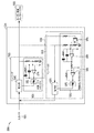
図2は、実施形態に従う極低温クーラー用モーター駆動パワーエレクトロニクスシステム200を表す。入力バス210はアクティブラインフィルタ220へ結合されている。アクティブラインフィルタ220は、入力バス210から引き込まれる調整された入力電流212を供給して、入力バス210へ反射されるリプル電流を低減する。アクティブラインフィルタ220は、入力バス210からエネルギ保持キャパシタンス224への双方向の電力フロー221を供給し、且つ、調整された出力電圧222をエネルギ保持キャパシタンス224にわたって供給する。
FIG. 2 illustrates a motor driven
エネルギ保持キャパシタンス224は、アクティブラインフィルタ220の出力部にあるコンプレッサモーター駆動エレクトロニクス230及び双方向LVPS240のための局所入力電源として働く。コンプレッサモーター駆動エレクトロニクス230によって引き込まれる負荷電流に双方向LVPS240によって引き込まれる負荷電流を足したものがアクティブラインフィルタ220によって供給される電流に満たない間は、エネルギ保持キャパシタンス224は、アクティブラインフィルタ220によって供給される電流と、コンプレッサモーター駆動エレクトロニクス230によって引き込まれる負荷電流に双方向LVPS240によって引き込まれる負荷電流を足したものとの間の差によって再充電される。コンプレッサモーター駆動エレクトロニクス230によって引き込まれる負荷電流に双方向LVPS240によって引き込まれる負荷電流を足したものがアクティブラインフィルタ220によって供給される電流よりも大きい間は、エネルギ保持キャパシタンス224は、コンプレッサモーター駆動エレクトロニクス230によって引き込まれる負荷電流に双方向LVPS240によって引き込まれる負荷電流を足したものと、アクティブラインフィルタ220によって供給される電流との間の電流の差を供給する。
The
実施形態に従って、アクティブラインフィルタ220は、極めて低いバンド幅制御ループを備えた高スイッチング周波数連続電流ブーストコンバータであってよい。アクティブラインフィルタ220はまた、多数の他のスイッチングコンバータトポロジのいずれを利用してもよく、絶縁又は非絶縁出力を供給する。アクティブラインフィルタ220は、入力バス210から引き込まれる調整された入力電流212に極めて遅い出力電圧調整ループを提供するよう電流モード制御を用いて作動してよい。アクティブラインフィルタ220は、出力電圧フィードフォワードによるピーク電流モード制御、平均電流モード制御、又は調整された出力電圧222における出力電圧リプルに応じて入力電流212を変調しないように変形された平均電流モード制御を利用してよい。アクティブラインフィルタ220は、代替的に、電圧モード制御又はヒステリシス電流制御を用いて作動してよい。アクティブラインフィルタ220はまた、入力電圧トランジェントに対して及び出力負荷トランジェントに対して非常に速い応答を提供して、エネルギ保持キャパシタンス224において出力電圧222の調整を保つよう、入力電圧フィードフォワード信号(図示せず。)及び出力負荷フィードフォワード信号(図示せず。)を利用してよい。入力バス210から引き込まれる入力電流をDCレベルに調整することによって、アクティブラインフィルタ220は、エネルギ保持キャパシタンス224からコンプレッサモーター駆動エレクトロニクス230によって引き込まれる負荷電流と比べて、有意に減衰された電流リプルをDC電流引き込みにもたらす。実施形態に従って、アクティブラインフィルタ220は、パッシブフィルタリングと比較して有意に低減されたサイズ及び重量において高スイッチング周波数で高い効率を保つよう、炭化ケイ素出力整流器を用いて実装されてよい。アクティブラインフィルタ220は、構成可能インターフェイス226を用いて、制御エレクトロニクス260からの信号によって制御されてよく、あるいは、制御エレクトロニクス260へステータス報告を供給してよく、あるいは、その両方を行ってよい。
According to an embodiment, the
コンプレッサモーター駆動エレクトロニクス230は、エネルギ保持キャパシタンス224へ結合されており、コンプレッサモーター232が電力をシンクしている場合にはモーター232へ駆動電力を供給し、コンプレッサモーター232が電力を供給している場合にはコンプレッサモーター232からエネルギ保持キャパシタンス224へ電力を戻す。然るに、コンプレッサモーター駆動エレクトロニクス230は、双方向の電力フロー234を供給する。コンプレッサモーター駆動エレクトロニクス230は、相当のリプル電流を引き込んでよい。コンプレッサモーター駆動エレクトロニクス230は、エネルギ保持キャパシタンス224から絶縁されている、又はエネルギ保持キャパシタンス224から絶縁されていないコンプレッサモーター232へ電力を供給してよい。コンプレッサモーター駆動エレクトロニクス230は、構成可能インターフェイス236を用いて、制御エレクトロニクス260からの信号によって制御されてよく、あるいは、制御エレクトロニクス260へステータス報告を供給してよく、あるいは、その両方を行ってよい。
The compressor
双方向低電圧電源(LVPS)240は、エネルギ保持キャパシタンス224へ結合されており、エネルギ保持キャパシタンス224に蓄えられているエネルギによって給電される。双方向LVPSは、双方向電力255をエキスパンダ及びバランサモーター駆動エレクトロニクス250へ供給してよく、バイアス電力225をアクティブラインフィルタ220へ供給してよく、バイアス電力235をコンプレッサモーター駆動エレクトロニクス230へ供給してよく、そして、エキスパンダ及びバランサモーター駆動エレクトロニクス250からエネルギ保持キャパシタンス224へ電力255を戻してよい。然るに、双方向LVPS240は、双方向電力フロー244を供給する。実施形態に従って、双方向LVPS240は、2つの電力コンバータ(図2に図示せず。)を使用してよく、第1の電力コンバータは、電力255をエキスパンダ及びバランサモーター駆動エレクトロニクス250へ供給してよく、バイアス電力225をアクティブラインフィルタ220へ供給してよく、バイアス電力235をコンプレッサモーター駆動エレクトロニクス230へ供給してよく、第2の電力コンバータは、電力255をエキスパンダ及びバランサモーター駆動エレクトロニクス250からシンクし、電力をエネルギ保持キャパシタンス224へ戻してよい。双方向LVPS240は、電力255をエキスパンダ及びバランサモーター駆動エレクトロニクス250へ、電力225をアクティブラインフィルタ220へ、そして、電力235を、エネルギ保持キャパシタンス224から絶縁されている、又はエネルギ保持キャパシタンス224から絶縁されていないコンプレッサモーター駆動エレクトロニクス230へ供給してよい。双方向LVPS240は、構成可能インターフェイス246を用いて、制御エレクトロニクス260からの信号によって制御されてよく、あるいは、制御エレクトロニクス260へステータス報告を供給してよく、あるいは、その両方を行ってよい。
A bidirectional low voltage power supply (LVPS) 240 is coupled to the
双方向LVPS240は、代替的に、2つよりも多い電力コンバータを使用してよく(図2に図示せず。)、例えば、第1の電力コンバータは、電力255をエキスパンダ及びバランサモーター駆動エレクトロニクス250へ供給してよく、第2のコンバータは、バイアス電力225をアクティブラインフィルタ220へ供給してよく、且つ、バイアス電力235をコンプレッサモーター駆動エレクトロニクス230へ供給してよく、そして、第3のコンバータは、シンク電力255をエキスパンダ及びバランサモーター駆動エレクトロニクス250へ供給し、電力をエネルギ保持キャパシタンス224へ戻してよい。他のコンバータは、他の例として、独立した電力を制御エレクトロニクスへ供給するために加えられてよい。なお、2つのコンバータが、双方向LVPSの動作を説明するために本願では記載される。
The
エキスパンダ及びバランサモーター駆動エレクトロニクス250は、双方向LVPS240へ結合されている。エキスパンダ及びバランサモーター駆動エレクトロニクス250は、エキスパンダ及びバランサモーター252及び253の動作を制御する。エキスパンダ及びバランサモーター駆動エレクトロニクス250は、駆動電力をエキスパンダ及びバランサモーター252及び253へ供給し、モーターが電力を供給している場合にはエキスパンダ及びバランサモーター252及び253から電力をシンクし、双方向LVPS240の出力部へ電力を戻す。然るに、エキスパンダ及びバランサモーター駆動エレクトロニクス250は、双方向電力フロー254を供給する。エキスパンダ及びバランサモーター駆動エレクトロニクス250は、双方向LVPS240の出力部から絶縁されている双方向電力フロー254を供給してよく、あるいは、双方向LVPS240の出力部から絶縁されていない双方向電力フロー254を供給してよい。エキスパンダ及びバランサモーター駆動エレクトロニクス250は、構成可能インターフェイス256を用いて、制御エレクトロニクス260からの信号によって制御されてよく、あるいは、制御エレクトロニクス260へステータス報告を供給してよく、あるいは、その両方を行ってよい。
Expander and balancer
図3は、単方向LVPS340が電力をモーター駆動エレクトロニクス350へ供給し、且つ、モーターから供給される電力が抵抗負荷315で散逸されるモーター駆動システム300を示す。図3において、モーター駆動エレクトロニクス350は、低電圧電源(LVPS)340を通じて給電される。LVPS340は、モーター駆動エレクトロニクス350が、モーター352を直接駆動するよう、入力バスから一直線に作動する場合には、省略されてよい。図3において、単方向入力フロー344は、入力電源310によって供給される。低電圧電源(LVPS)340は、電力をモーター駆動エレクトロニクス350へ供給するために入力電源310を使用する。LVPS340は、入力電源310から絶縁されているモーター駆動エレクトロニクス350へ電力を供給する。代替的に、LVPS340は非絶縁電力を供給してよい。モーター駆動エレクトロニクス350は、電力をモーター352からシンクすること及び電力をモーターへ供給することによって、モーター352のための双方向電力フロー354を供給する。調整を保つよう、モーター352から供給される電力は、負荷抵抗315で散逸される。負荷抵抗315の抵抗は、LVPS340がいつでも電力を供給するよう有意に低い。
FIG. 3 shows a
モーター駆動エレクトロニクス350がLVPS340によって供給される二次電力から離れて作動するような用途に関して、双方向LVPS(図示せず。)は電力を供給し、且つ、電力をシンクし、シンクされた電力を入力電源へ戻す。電力を入力電源へ戻すことによって、システム電力散逸は低減され、システム全体の効率は改善され得る。加えて、電力を入力へ戻すLVPS双方向電力コンバータは、システムの熱負荷を低減することができる。
For applications where the
図4は、実施形態に従うモーター駆動システム400のブロック図である。図4において、双方向低電圧電源(LVPS)440は、電力をモーター駆動エレクトロニクス450へ供給し、且つ電力をモーター452から入力電源410へ戻す。然るに、双方向LVPS440は、双方向電力フロー444を供給する。LVPS440は、入力電源410から絶縁されるモーター駆動エレクトロニクス450へ電力を供給してよい。代替的に、LVPS440は非絶縁電力を供給してよい。モーター駆動システム400において、負荷抵抗器は、調整を保つことを目的としてモーター452から供給される電力を散逸させるために必要とされない。モーター駆動エレクトロニクス450を通る電力フローは、双方向電力フロー454である。 FIG. 4 is a block diagram of a motor drive system 400 according to an embodiment. In FIG. 4, a bidirectional low voltage power supply (LVPS) 440 supplies power to the motor drive electronics 450 and returns power from the motor 452 to the input power supply 410. However, bidirectional LVPS 440 provides bidirectional power flow 444. The LVPS 440 may supply power to the motor drive electronics 450 that is isolated from the input power source 410. Alternatively, LVPS 440 may provide non-isolated power. In motor drive system 400, a load resistor is not required to dissipate the power supplied from motor 452 for the purpose of maintaining regulation. The power flow through the motor drive electronics 450 is a bidirectional power flow 454.
図5は、同期整流を使用する絶縁型多スイッチ式双方向電力コンバータ540が、絶縁低電圧電力をモーター駆動エレクトロニクス550へ供給し、あるいは、電力をモーター駆動エレクトロニクス550からシンクして電力をソース510へ戻すモーター駆動システム500を示す。図5において、入力電源510が電力を供給しているとき、LVPS540は、電力をモーター駆動エレクトロニクス550へ供給するフルブリッジコンバータとして動作する。モーター552が電力を供給している場合に、LVPS540の出力電流の方向は逆になり、LVPS540は、LVPSの出力部から入力電源510へ電力を伝送する電流給電型(current-fed)コンバータとして動作し始める。LVPS制御エレクトロニクス549は、多スイッチ式双方向電力コンバータ540の動作を制御する。例えば、トランジスタQ1 541、Q2 545、Q3 542、Q4 543、Q5 547及びQ6 548の動作は、電力の供給及びシンクを制御するために使用される。
FIG. 5 shows that an isolated multi-switch
然るに、多スイッチ式双方向電力コンバータ540は、同期整流器による電圧ダブラー(doubler)出力整流を使用してフルブリッジコンバータを提供する。なお、図5に示されている多スイッチ式双方向電力コンバータ540は、2つの単純なコンバータのためよりも多い部品を含み(例えば、2つの単純なコンバータのための2つのトランジスタに対して6つのトランジスタ)(例えば、図9を参照)、相応により大きい基板面積及び容量を含む。双方向電力フローのために使用され得る多数の他の代替のタイプの電力コンバータトポロジが存在する。代替案の一例において、双方向フライバックコンバータは、3つのパワーMOSFET、3つのパワー整流器、四巻線変圧器、及びパルス幅変調(PWM;pulse width modulation)コントローラを使用する。
However, the multi-switch
高電力システムのために、同期整流を使用する多スイッチ式双方向電力コンバータ540は、電力を供給及びシンクし、シンクされた電力を入力電源510へ戻して、システムの電力散逸を低減し且つシステム全体の効率を改善するために使用されてよい。なお、低電力システムのために、多スイッチ式双方向電力コンバータのボリューム、費用及び複雑さは正当化され得ない。
For high power systems, the multi-switch
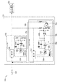
図6は、実施形態に従って、双方向LVPS614を使用するモーター駆動システム600のブロック図である。図6において、LVPS614は、モーター駆動エレクトロニクス616への出力電圧を調整するよう構成された2つの単純な、ディスクリートの、安価なコンバータ622、624を含む。LVPS614は、入力電源610から絶縁されるモーター駆動エレクトロニクス616へ電力を供給してよい。代替的に、LVPS614は非絶縁電力を供給してよい。第2のディスクリートコンバータ624は、反対の向きで第1のディスクリートコンバータ622と並列に結合されている。第1のコンバータ622は、モーターが負荷として駆動されている場合に、入力電源610からモーター駆動エレクトロニクス616へ電力を供給し、モーター駆動エレクトロニクス616への電圧を調整する。第1の電力コンバータ622は、このように、電力をモーター駆動エレクトロニクス616へ供給し、一方、第2の電力コンバータ624はオフである。その後に、モーターが電源として機能している場合に、第1のコンバータの出力電圧は増大し、第1のコンバータは遮断し、そして、第2のコンバータ624はモーター駆動エレクトロニクス616から電力をシンクし、モーター駆動エレクトロニクス616への電圧を調整しながら電力を入力電源610へ供給する。このように、電力がモーターによって供給されている場合に、例えば、冷却発展フェーズの間に、第1の電力コンバータ622はオフし、第2の電力コンバータ624はオンして、モーター駆動エレクトロニクス616から入力電源610へ電力を戻す。第1のディスクリート電力コンバータ622は、第1の電力段640及び第1の制御エレクトロニクス620を含む。第1の制御エレクトロニクス620は、第1の誤差増幅器630を含む。第2の電力コンバータ624は、第2の電力段670及び第2の制御エレクトロニクス650を含む。第2の制御エレクトロニクス650は、第2の誤差増幅器660を含む。誤差増幅器660は、モーター駆動エレクトロニクス616への電圧を、誤差増幅器630が調整するためにバイアスをかけられる電圧よりもわずかに高い電圧に調整するようバイアスをかけられる。
FIG. 6 is a block diagram of a
双方向LVPSコンバータ614は、電力をモーター駆動エレクトロニクス616へ供給するよう入力電源610へ結合されている。モーターが負荷として動作している場合に、第1のディスクリートコンバータ622は電力を供給し、モーター駆動エレクトロニクス616への電圧を所定の電圧に調整する。モーターが電源として機能し、モーター駆動エレクトロニクス616が第1のコンバータ622の出力部へ電力を戻す場合に、第1のコンバータ622の出力部での電圧は増大し、誤差増幅器630は電力段640を遮断し、第1のディスクリートコンバータ622の出力電力は、出力電圧がローに下がる時点までゼロへと低減される。第1のコンバータ622の出力部での電圧が十分に増大する場合に、誤差増幅器660は、モーター駆動エレクトロニクス616から電力をシンクして、電力を入力電源610へ供給するよう、電力段670をオンする。これは、モーター駆動エレクトロニクス616への電圧を低下させる。
Bidirectional
反対に、モーター駆動エレクトロニクス616への電圧が過剰に低下する場合には、第2のディスクリートコンバータ624のデューティーサイクル及び出力電力は低減されて、モーター駆動エレクトロニクス616からシンクされる電力は減り、入力電源610へ供給される電力は減る。このようにして、モーター駆動エレクトロニクス616への電圧は増大することができる。モーター駆動エレクトロニクス616への電圧が十分に低下する場合には、第2のディスクリートコンバータ624のデューティーサイクル及び出力電力は、出力電圧がハイになる時点まで、ゼロへと低減される。
Conversely, if the voltage to the
当業者であれば、2つのディスクリートコンバータ622、624は、絶縁フライバックコンバータ、絶縁フォワードコンバータ、若しくは夫々についてそれら一方、又は何らかの他のトポロジであってよいことを認識するだろう。しかし、実施形態は、それに関して制限されるよう意図されない点に留意されたい。入力電源610は、一次電力から予め絶縁されてよく、その場合に、2つのディスクリートコンバータ622、624は非絶縁コンバータであってよい。なお、実施形態は、それに関して制限されない。
One skilled in the art will recognize that the two
双方向LVPSは、代替的に、2つよりも多い電力コンバータを使用してよい(図6に図示せず。)。例えば、1つの電力コンバータは、低電力駆動エレクトロニクスへ電力を供給してよく、第2のコンバータは、アクティブラインフィルタへ及び高電力モーター駆動エレクトロニクスへバイアス電力を供給してよく、第3のコンバータは、低電力駆動エレクトロニクスから電力をシンクし、電力をエネルギ保持キャパシタンスへ戻してよい。他のコンバータは、他の例として、独立した電力を制御エレクトロニクスへ供給するよう加えられてよい。2つの電力コンバータが本願では論じられているが、図は制限ではなく説明のために論じられており、実施形態はそれに関して制限されないことが理解されるべきである。 Bidirectional LVPS may alternatively use more than two power converters (not shown in FIG. 6). For example, one power converter may supply power to the low power drive electronics, a second converter may supply bias power to the active line filter and to the high power motor drive electronics, and a third converter The power may be sinked from the low power drive electronics and returned to the energy holding capacitance. Other converters may be added to provide independent power to the control electronics as another example. Although two power converters are discussed herein, it should be understood that the figures are discussed for purposes of illustration and not limitation, and embodiments are not limited in that regard.
成分値の初期許容量、ドリフト、又は温度係数に起因して、第2のディスクリートコンバータ624の電圧設定点は、第1のディスクリートコンバータ622の電圧設定点よりも低い方にドリフトすることがある。その場合に、2つの単純なコンバータは同時にオンして、電力をループにおいて循環させる。そのような電力の循環は、電力を浪費し、効率を低下させる。ディスクリートコンバータ622、622が同時にオンすることを防ぐ1つの方法は、第2のディスクリートコンバータ624のために相当により高い電圧調整設定点を使用することである。他の方法は、第1のディスクリートコンバータ622が動作しているときに第2のディスクリートコンバータ624をオフに保つことである。
Due to the initial tolerance of component values, drift, or temperature coefficient, the voltage set point of the second
第1のディスクリートコンバータ622が電圧モード制御又は電流モード制御を使用するかどうかにかかわらず、第1のディスクリートコンバータ622の第1の誤差増幅器630の出力電圧は、モーターが電源として動作しており、コンバータ622の出力電圧が増大している時間中に、より低い出力電圧を得るようローに落ちる。また、第1のディスクリートコンバータ622の第1の誤差増幅器6340の出力電圧は、モーターが負荷として動作しており、コンバータ622の出力電圧が低下している時間中に、より高い出力電圧を得るようハイに上がる。このように、第1のディスクリートコンバータ622の第1の誤差増幅器630の出力電圧は、より多いスループット電力又は出力電圧が必要とされるかどうか、又はより少ないスループット電力又は出力電圧が必要とされるかどうかを示し、よって、第1のディスクリートコンバータ622の第1の誤差増幅器630の出力電圧は、第2のディスクリートコンバータ624をオン又はオフするようトリガするために使用されてよい。
Regardless of whether the first
第2のディスクリートコンバータ624を有効にするために、あるいは、反対に、第2のディスクリートコンバータ624を無効にするために、第1のディスクリートコンバータ622の第1の誤差増幅器630の出力電圧を使用するいくつかの方法がある。
The output voltage of the first error amplifier 630 of the first
また、ブロック図で表される双方向LVPSを実装するいくつかの方法がある。双方向LVPSの実施形態の数例がここで与えられる。なお、それらの数例は実例であって制限されない点が留意されるべきである。 There are also several ways to implement the bi-directional LVPS represented in the block diagram. Several examples of bi-directional LVPS embodiments are given here. It should be noted that these examples are illustrative and not limiting.
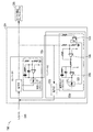
図7は、実施形態に従って、2つのコンバータを使用する双方向低電圧電源(LVPS)714を使用するモーター駆動システム700のブロック図である。LVPS714は、入力電源710から絶縁されるモーター駆動エレクトロニクス716へ電力を供給してよい。代替的に、LVPS714は非絶縁電力を供給してよい。図7において、双方向低電圧電源(LVPS)714は、第1のディスクリート電力コンバータ722及び第2のディスクリート電力コンバータ724を含む。第1のディスクリート電力コンバータ722は、第1の電力段740及び第1の制御エレクトロニクス720を含む。第1の制御エレクトロニクス720は、第1の誤差増幅器730を含む。第2の電力コンバータ724は、第2の電力段770及び第2の制御エレクトロニクス750を含む。第2の制御エレクトロニクス750は、第2の誤差増幅器760を含む。図7において、第2のコンバータ724は、信号736を用いて第1のコンバータ722の誤差増幅器730によって制御される。信号736は、誤差増幅器730の直接出力であってよく、あるいは、誤差増幅器730の出力から生成された信号であってよい。
FIG. 7 is a block diagram of a
双方向LVPSコンバータ714は、電力をモーター駆動エレクトロニクス716へ供給するよう入力電源710へ結合されている。モーターが負荷として動作している場合に、第1のディスクリートコンバータ722は電力を供給し、モーター駆動エレクトロニクス716への電圧を第1のディスクリート電力コンバータ722の出力部での所定の電圧に調整する。誤差増幅器730は、信号736によって第2のディスクリートコンバータ724をオフしたままとする。モーターが電源として機能し、モーター駆動エレクトロニクス716が第1のコンバータ722の出力部へ電力を戻す場合に、第1のコンバータ722の出力部での電圧は増大し、誤差増幅器730は電力段740を遮断し、第1のディスクリートコンバータ722の出力電力は、出力電圧が下がる時点までゼロへと低減される。誤差増幅器730がローに落ちることは、信号736によって第2のコンバータ724を有効にする。第1のコンバータ722の出力部での電圧が十分に増大する場合に、誤差増幅器760は、モーター駆動エレクトロニクス716から電力をシンクして、電力を入力電源710へ供給するよう、第2のディスクリートコンバータ724の電力段770をオンする。これは、モーター駆動エレクトロニクス716への電圧を低下させる。
Bidirectional
モーター駆動エレクトロニクス716への電圧が増大する場合には、第2のディスクリートコンバータ724のデューティーサイクル(及び出力電力)は、モーター駆動エレクトロニクス716から追加の電力をシンクし、追加の電力を入力電源710へ供給するよう、増大する。これは、モーター駆動エレクトロニクス716への電圧を低下させる。
When the voltage to the
反対に、モーター駆動エレクトロニクス716への電圧が低下する場合には、第2のディスクリートコンバータ724のデューティーサイクル及び出力電力は低減されて、モーター駆動エレクトロニクス716からシンクされる電力は減り、入力電源710へ供給される電力は減る。このようにして、モーター駆動エレクトロニクス716への電圧は調整される。
Conversely, if the voltage to the
モーターが再び負荷として動作し、モーター駆動エレクトロニクス716が第1のコンバータ722の出力部から電力を引き込む場合に、第1のコンバータ722の出力部での電圧は低下する。誤差増幅器730は、より低い電圧を検知し、その出力電圧を増大させて、電力段740を有効にし、そして、第1のディスクリートコンバータ722は、電力を供給し、モーター駆動エレクトロニクス716への電圧を所定の電圧に調整する。誤差増幅器730はまた、信号736によって第2のディスクリートコンバータ724をオフしたままとする。このように、図7の双方向LVPS714において、第1のディスクリート電力コンバータ722の誤差増幅器730の出力電圧は、第2のディスクリート電力コンバータ724を制御するために使用される。
When the motor operates again as a load and the
図8は、実施形態に従って、2つのコンバータを使用する双方向低電圧電源(LVPS)814の概略図を示すモーター駆動システム800のブロック図である。LVPS814は、入力電源810から絶縁されるモーター駆動エレクトロニクス816へ電力を供給してよい。代替的に、LVPS814は非絶縁電力を供給してよい。双方向LVPS814は、第1のディスクリート電力コンバータ822及び第2のディスクリート電力コンバータ824を含む。第1のディスクリート電力コンバータ822は、第1の電力段840及び第1の制御エレクトロニクス820を含む。第1の制御エレクトロニクス820は、第1の誤差増幅器830及び第1のパルス幅変調器(PWM)832を含む。第1のPWM832は、誤差増幅器830の出力電圧を電力段840におけるスイッチトランジスタのデューティーサイクルに変換するために使用され、そうすることによって、誤差増幅器830がコンバータ電力段840の出力電力を制御することを可能にする。第2の電力コンバータ824は、第2の電力段870及び第2の制御エレクトロニクス850を含む。第2の制御エレクトロニクス850は、第2の誤差増幅器860、第2のパルス幅変調器(PWM)872、及び反転増幅器880を含む。PWM872は、反転増幅器880の出力電圧を電力段870におけるスイッチトランジスタのデューティーサイクルに変換するために使用され、そうすることによって、誤差増幅器860がコンバータ電力段870の出力電力を制御することを可能にする。双方向LVPS814は、電力をモーター駆動エレクトロニクス816へ供給するよう入力電源810へ結合されている。
FIG. 8 is a block diagram of a
図8において、第2のディスクリートコンバータ824は、誤差増幅器860の後に置かれた追加の反転増幅器880を用いて調整する。第2のディスクリートコンバータ824は、モーター駆動エレクトロニクス816への電圧を、第1のディスクリートコンバータ822の設計された出力電圧よりもわずかに高い電圧に調整する。
In FIG. 8, the second
誤差増幅器860の後の反転増幅器880は、モーター駆動エレクトロニクス816への電圧が増大する場合に第2のディスクリートコンバータ824のデューティーサイクル及び出力電力を増大させて、追加の電力がモーター駆動エレクトロニクス816からシンクされ、追加の電力が入力電源810へ供給されるようにする。これは、モーター駆動エレクトロニクス816への電圧を低下させる。反対に、モーター駆動エレクトロニクス816への電圧が低下する場合には、第2のディスクリートコンバータ824のデューティーサイクル及び出力電力は低減され、モーター駆動エレクトロニクス816からシンクされる電力は減り、入力電源810へ供給される電力は減る。これにより、モーター駆動エレクトロニクス816への電圧は増大され得る。
The inverting
例えば、第1のディスクリートコンバータ822は、+15.0Vの出力電圧を調整するよう設定されてよく、第2のディスクリートコンバータ824は、+15.5Vの出力電圧を調整するよう設定されてよい。モーターが負荷として動作する場合に、第1のディスクリートコンバータ822は、電力をモーター駆動エレクトロニクス816へ供給し、出力電圧を+15.0Vに調整する。LVPS出力電圧は+15.5Vに満たないから、第2の誤差増幅器860への出力電圧フィードバックはローであり、第2の誤差増幅器860の出力はハイであり、反転増幅器880の出力はローになって、第2のディスクリート電力段870を遮断する。モーターが電力を供給する場合に、第1のディスクリートコンバータ822の出力電圧は15.0Vよりも高くなり、第1の誤差増幅器830の出力はローに落ち、第1のディスクリートコンバータ822を通って出力への電力の伝送を遮断する。モーター駆動エレクトロニクス816への電圧が15.5Vに達する場合に、第2の誤差増幅器860はローになり、反転増幅器880の出力はハイになって、第2のディスクリート電力段870をオンし、第2のディスクリート電力段870は、電力を入力電源810へ戻す。第2のディスクリートコンバータ824は、電力を入力電源810へ戻すことによって、モーター駆動エレクトロニクス816への電圧を+15.5Vに調整する。
For example, the first
図9は、他の実施形態に従って、2つのコンバータを使用する双方向低電圧電源(LVPS)914の概略図を示すモーター駆動システム900のブロック図である。双方向LVPS914は、入力電源910から絶縁されるモーター駆動エレクトロニクス716へ電力を供給してよい。代替的に、LVPS914は非絶縁電力を供給してよい。双方向LVPS914は、第1のディスクリート電力コンバータ922及び第2のディスクリート電力コンバータ924を含む。第1のディスクリート電力コンバータ922は、入力電源910へ結合されており、第1の電力段940及び第1の制御エレクトロニクス920を含む。第1の制御エレクトロニクス920は、第1の誤差増幅器930及びパルス幅変調器(PWM)932を含む。PWM932は、誤差増幅器930の出力電圧を電力段940におけるスイッチトランジスタのデューティーサイクルに変換するために使用され、そうすることによって、誤差増幅器930がコンバータ電力段940の出力電力を制御することを可能にする。第2の電力コンバータ924は、第2の電力段970及び第2の制御エレクトロニクス950を含む。第2の制御エレクトロニクス950は、第2の誤差増幅器960、パルス幅変調器(PWM)972、及び反転増幅器980を含む。PWM972は、誤差増幅器960の出力電圧を電力段970におけるスイッチトランジスタのデューティーサイクルに変換するために使用され、そうすることによって、誤差増幅器960がコンバータ電力段970の出力電力を制御することを可能にする。誤差増幅器960の前の反転増幅器980は、モーター駆動エレクトロニクス916への電圧が増大する場合に第2のディスクリートコンバータ924のデューティーサイクル及び出力電力を増大させて、追加の電力がモーター駆動エレクトロニクス916からシンクされ、追加の電力が入力電源910へ供給されるようにする。これは、モーター駆動エレクトロニクス916への電圧を低下させる。反対に、モーター駆動エレクトロニクス916への電圧が低下する場合には、第2のディスクリートコンバータ924のデューティーサイクル及び出力電力は低減され、モーター駆動エレクトロニクス916からシンクされる電力は減り、入力電源910へ供給される電力は減る。これにより、モーター駆動エレクトロニクス916への電圧は増大され得る。双方向LVPS914は、電力をモーター駆動エレクトロニクス916へ供給するよう入力電源910へ結合されている。
FIG. 9 is a block diagram of a
図10は、他の実施形態に従って、2つのコンバータを使用する双方向低電圧電源(LVPS)1014の概略図を示すモーター駆動システム1000のブロック図である。双方向LVPS1014は、電力をモーター駆動エレクトロニクス1016へ供給するよう入力電源1010へ結合されている。LVPS1014は、入力電源1010から絶縁されるモーター駆動エレクトロニクス1016へ電力を供給してよい。代替的に、LVPS1014は非絶縁電力を供給してよい。双方向LVPS1014は、第1のディスクリート電力コンバータ1022及び第2のディスクリート電力コンバータ1024を含む。第1のディスクリート電力コンバータ1022は、第1の電力段1040及び第1の制御エレクトロニクス1020を含む。第1の制御エレクトロニクス1020は、第1の誤差増幅器1030及びパルス幅変調器(PWM)1032を含む。PWM1032は、誤差増幅器1030の出力電圧を電力段1040におけるスイッチトランジスタのデューティーサイクルに変換するために使用され、そうすることによって、誤差増幅器1030がコンバータ電力段1040の出力電力を制御することを可能にする。第2の電力コンバータ1024は、第2の電力段1070及び第2の制御エレクトロニクス1050を含む。第2の制御エレクトロニクス1050は、第2の誤差増幅器1060、パルス幅変調器(PWM)1072、反転増幅器1080、及び制御スイッチングデバイス1034を含む。PWM1072は、反転増幅器1080の出力電圧を電力段1070におけるスイッチトランジスタのデューティーサイクルに変換するために使用され、そうすることによって、誤差増幅器1060がコンバータ電力段1070の出力電力を制御することを可能にする。誤差増幅器1060の後の反転増幅器1080は、モーター駆動エレクトロニクス1016への電圧が増大する場合に第2のディスクリートコンバータ1024のデューティーサイクル及び出力電力を増大させて、追加の電力がモーター駆動エレクトロニクス1016からシンクされ、追加の電力が入力電源1010へ供給されるようにする。これは、モーター駆動エレクトロニクス1016への電圧を低下させる。図10に示されている双方向LVPS1014は、第1のコンバータ1022の誤差増幅器1030の出力からの信号1036を用いて、第2のコンバータ1024の動作を制御する。信号1036は、誤差増幅器1030の直接の出力であってよく、あるいは、誤差増幅器1030の出力から生成される信号であってよい。制御スイッチングデバイス1034は、バイポーラトランジスタQ1として示されているが、多数の制御スイッチングデバイス(例えば、MOSFET、コンパレータ、光カプラ、演算増幅器、など)のいずれも使用されてよい。
FIG. 10 is a block diagram of a
図10において、トランジスタQ1 1034は、第1の誤差増幅器1030からの信号1036を用いて第2のディスクリートコンバータ1024のオン/オフ状態を制御するよう第2の制御エレクトロニクス1050に加えられている。それにより、第2のディスクリートコンバータ1024は、第1のディスクリートコンバータ1022の第1の誤差増幅器1030の出力電圧がローになるまで、オフ状態に保たれる。モーターが負荷として動作しており、モーター駆動エレクトロニクス1016から電力を引き込む場合に、第1のディスクリートコンバータ1022は、電力をモーター駆動エレクトロニクス1016へ供給し、モーター駆動エレクトロニクス1016は、モーター駆動電流に基づきモーターを駆動する。第1のディスクリートコンバータ1022の第1の誤差増幅器1030は、高電圧レベルにあり、実際の電圧レベルは、使用されるPWM、コンバータ設計、入力バス電圧、及びモーター駆動エレクトロニクスによって引き込まれる電力に依存する。トランジスタQ1 1034はオンされ、第2の誤差増幅器1060への入力をローに保ち、第2のディスクリートコンバータ1024をオフのままとする。
In FIG. 10,
モーターが電源として動作しており、電力をモーター駆動エレクトロニクス1016へ供給する場合に、第1のディスクリートコンバータ1022の出力電圧は増大し、第1の誤差増幅器1030の出力電圧はローになり、第1のディスクリートコンバータ1022からモーター駆動エレクトロニクス1016への電力の移動を遮断し、トランジスタQ1 1034をオフする。トランジスタQ1 1034がオフすると、第2の誤差増幅器1060へのフィードバック電圧はハイになり、第2の誤差増幅器1060は高電圧を検知し、第2の誤差増幅器1060の出力電圧はローに落ちる。反転増幅器1080の出力はハイになり、電力が入力電源1010へ戻されるように指示する。第2のディスクリートコンバータ1024は、電力を入力電源1010へ戻すことによって、モーター駆動エレクトロニクス1016への電圧を調整する。第2のディスクリートコンバータ1024は、モーター駆動エレクトロニクス1016への電圧の調整を保つよう、モーターが供給することができるよりも多い電力を伝送することが可能であってよい。
When the motor is operating as a power source and power is supplied to the
トランジスタQ1 1034の追加は、第1の誤差増幅器1030の出力電圧によって第2のディスクリートコンバータ1024の動作を制御する方法の一例である。代替的に、コンパレータ又は他の回路が、第1のディスクリートコンバータ1022の第1の誤差増幅器1030の出力電圧から生成された信号1036を用いて第2のディスクリートコンバータ1024の動作を制御するために使用されてよい。加えて、他の手段が、第1のディスクリートコンバータ1022の第1の誤差増幅器1030の出力電圧から生成された信号1036を用いて第2のディスクリートコンバータ1024の動作を制御するために使用されてよい。例えば、いくつかのPWMは、PWMを無効にしてコンバータをオフするシャットダウンピンを設ける。他のPWMでは、誤差増幅器の出力は、PWMを無効にするよう接地に引っ張られてよい。なお、当業者ならば、実施形態はこれに関して制限されるよう意図されないことを認識するだろう。理解されるべき考えは、第2のコンバータがオン又はオフであるかどうかを制御するために第1の誤差増幅器の出力電圧が使用され得ることである。コンバータは、高速リカバリダイオード、超高速リカバリダイオード、ショットキーダイオード、高電圧ショットキーダイオード、炭化ケイ素(SiC)整流器、又は同期整流を使用してよい。更には、コンバータは、ハードスイッチド・コンバータ、ソフトスイッチド・コンバータ、又は擬似共振(quasi-resonant)コンバータであってよい。コンバータは、リプルレギュレータであるか、あるいは、それを使用してよい。デジタル制御が使用されてよい。先と同じく、当業者であれば、実施形態はこれに関して制限されるよう意図されないことを認識するだろう。
The addition of the
図11は、他の実施形態に従って、2つのコンバータを使用する双方向低電圧電源(LVPS)1114の概略図を示すモーター駆動システム1100のブロック図である。双方向LVPS1114は、電力をモーター駆動エレクトロニクス1116へ供給するよう入力電源1110へ結合されている。LVPS1114は、入力電源1110から絶縁されるモーター駆動エレクトロニクス1116へ電力を供給してよい。代替的に、LVPS1114は非絶縁電力を供給してよい。双方向LVPS1114は、第1のディスクリート電力コンバータ1122及び第2のディスクリート電力コンバータ1124を含む。第1のディスクリート電力コンバータ1122は、第1の電力段1140及び第1の制御エレクトロニクス1120を含む。第1の制御エレクトロニクス1120は、第1の誤差増幅器1130及びパルス幅変調器(PWM)1132を含む。PWM1132は、誤差増幅器1130の出力電圧を電力段1140におけるスイッチトランジスタのデューティーサイクルに変換するために使用され、そうすることによって、誤差増幅器1130がコンバータ電力段1140の出力電力を制御することを可能にする。第2の電力コンバータ1124は、第2の電力段1170及び第2の制御エレクトロニクス1150を含む。第2の制御エレクトロニクス1150は、第2の誤差増幅器1160、パルス幅変調器(PWM)1172、反転増幅器1180、及び制御スイッチングデバイスQ1 1134を含む。PWM1172は、誤差増幅器1160の出力電圧を電力段1170におけるスイッチトランジスタのデューティーサイクルに変換するために使用され、そうすることによって、誤差増幅器1160がコンバータ電力段1170の出力電力を制御することを可能にする。誤差増幅器1160の前の反転増幅器1180は、モーター駆動エレクトロニクス1116への電圧が増大する場合に第2のディスクリートコンバータ1124のデューティーサイクル及び出力電力を増大させて、追加の電力がモーター駆動エレクトロニクス1116からシンクされ、追加の電力が入力電源1110へ供給されるようにする。これは、モーター駆動エレクトロニクス1116への電圧を低下させる。図11における双方向LVPS1114は、第1のコンバータ1122の誤差増幅器1130の出力からの信号1136を用いて、第2のコンバータ1124の動作を制御する。信号1136は、誤差増幅器1130の直接の出力であってよく、あるいは、誤差増幅器1130の出力から生成される信号であってよい。制御スイッチングデバイス1134は、NPNバイポーラトランジスタQ1として示されているが、多数の制御スイッチングデバイス(例えば、MOSFET、コンパレータ、光カプラ、演算増幅器、など)のいずれも使用されてよい。加えて、他の手段が、第1のディスクリートコンバータ1122の第1の誤差増幅器1130の出力電圧から生成された信号1136を用いて第2のディスクリートコンバータ1124の動作を制御するために使用されてよい。
FIG. 11 is a block diagram of a
図11において、第2の制御エレクトロニクス1150は、第1の誤差増幅器1130からの信号1136を用いて第2のディスクリートコンバータ1124のオン/オフ状態を制御するトランジスタQ1 1134を含む。それにより、第2のディスクリートコンバータ1124は、第1のディスクリートコンバータ1122の第1の誤差増幅器1130の出力電圧がローになるまで、オフ状態に保たれる。モーターが負荷として動作しており、モーター駆動エレクトロニクス1116から電力を引き込む場合に、第1のディスクリートコンバータ1122は、電力をモーター駆動エレクトロニクス1116へ供給し、モーター駆動エレクトロニクス1116はモーターを駆動する。第1のディスクリートコンバータ1122の第1の誤差増幅器1130は、高電圧レベルにあり、実際の電圧レベルは、使用されるPWM及びコンバータ設計、並びにスループット電力に依存する。トランジスタQ1 1134はオンされ、第2の誤差増幅器1160への入力をローに保ち、第2のディスクリートコンバータ1124をオフのままとする。
In FIG. 11, the
図12は、他の実施形態に従って、2つのコンバータを使用する双方向低電圧電源(LVPS)1214の概略図を示すとともに、第2のコンバータ1224を遮断する他の手段を表すモーター駆動システム1200のブロック図である。双方向LVPS1214は、電力をモーター駆動エレクトロニクス1216へ供給するよう入力電源1210へ結合されている。LVPS1214は、入力電源1210から絶縁されるモーター駆動エレクトロニクス1216へ電力を供給してよい。代替的に、LVPS1214は非絶縁電力を供給してよい。双方向LVPS1214は、第1のディスクリート電力コンバータ1222及び第2のディスクリート電力コンバータ1224を含む。第1のディスクリート電力コンバータ1222は、第1の電力段1240及び第1の制御エレクトロニクス1220を含む。第1の制御エレクトロニクス1220は、第1の誤差増幅器1230及びパルス幅変調器(PWM)1232を含む。PWM1232は、誤差増幅器1230の出力電圧を電力段1240におけるスイッチトランジスタのデューティーサイクルに変換するために使用され、そうすることによって、誤差増幅器1230がコンバータ電力段1240の出力電力を制御することを可能にする。第2の電力コンバータ1224は、第2の電力段1270及び第2の制御エレクトロニクス1250を含む。第2の制御エレクトロニクス1250は、第2の誤差増幅器1260、反転増幅器1280、パルス幅変調器(PWM)1272、及び制御スイッチングデバイスQ1 1234を含む。PWMデバイス1272は、誤差増幅器1260の出力電圧を電力段1270におけるスイッチトランジスタのデューティーサイクルに変換するために使用され、そうすることによって、誤差増幅器1260がコンバータ電力段1270の出力電力を制御することを可能にする。誤差増幅器1260の前の反転増幅器1280は、モーター駆動エレクトロニクス1216への電圧が増大する場合に第2のディスクリートコンバータ1224のデューティーサイクル及び出力電力を増大させて、追加の電力がモーター駆動エレクトロニクス1216からシンクされ、追加の電力が入力電源1210へ供給されるようにする。これは、モーター駆動エレクトロニクス1216への電圧を低下させる。なお、図12においては、第1の誤差増幅器1230からの信号1236又は誤差増幅器1230の出力から生成される信号を用いて第2のディスクリートコンバータ1224のオン/オフ状態を制御するために使用されるトランジスタQ1 1234は、第2のコンバータ1224を無効にするようPWM1272への信号1237を介して誤差増幅器1260の出力部へ結合されている。
FIG. 12 shows a schematic diagram of a bi-directional low voltage power supply (LVPS) 1214 that uses two converters, according to another embodiment, and a
図13は、他の実施形態に従って、2つのコンバータを使用する双方向低電圧電源(LVPS)1314の概略図を示すモーター駆動システム1300のブロック図である。双方向LVPS1314は、電力をモーター駆動エレクトロニクス1316へ供給するよう入力電源1310へ結合されている。第2の電力コンバータ1324は、第2の電力段1370及び第2の制御エレクトロニクス1350を含む。このように、双方向LVPS1314は、双方向LVPS1314の制御スイッチングデバイス1334が第2のコンバータ1324を無効にするようPWM1372の入力部でプルダウン1337を供給する点を除いて、図12に示されている双方向LVPS1214と同様である。
FIG. 13 is a block diagram of a
図14は、実施形態に従う双方向低電圧電源1414の概略図を示すモーター駆動システム1400のブロック図である。双方向LVPS1414は、電力をモーター駆動エレクトロニクス1416へ供給するようVin1411及びVinRTN(return)1413を介して入力電源1410へ結合されている。双方向LVPS1414は、入力電源から絶縁されるモーター駆動エレクトロニクスへ電力を供給する。代替的に、LVPS1414は、非絶縁電力を提供するよう構成されてよい。双方向LVPS1414は、第1のディスクリート電力コンバータ1422及び第2のディスクリート電力コンバータ4124を含む。第1のディスクリート電力コンバータ1422は、第1の電力段1440及び第1の制御エレクトロニクス1420を含む。第1の制御エレクトロニクス1420は、第1の誤差増幅器1430及びパルス幅変調器(PWM)1432を含む。PWM1432は、反転増幅器1430の出力電圧を電力段1440におけるスイッチトランジスタのデューティーサイクルに変換するために使用され、そうすることによって、誤差増幅器1430が電力段1440の出力電力を制御することを可能にする。電力段1440は、フォワードコンバータとして構成される。第2の電力コンバータ1424は、第2の電力段1470及び第2の制御エレクトロニクス1450を含む。第2の制御エレクトロニクス1450は、第2の誤差増幅器1460、パルス幅変調器(PWM)1472、及び反転増幅器1480を含む。PWMデバイス1472は、誤差増幅器1460の出力電圧を電力段1470におけるスイッチトランジスタのデューティーサイクルに変換するために使用され、そうすることによって、誤差増幅器1460が電力段1470の出力電力を制御することを可能にする。誤差増幅器1460の前の反転増幅器1480は、モーター駆動エレクトロニクス1416への電圧が増大する場合に第2のディスクリートコンバータ1424のデューティーサイクル及び出力電力を増大させて、追加の電力がモーター駆動エレクトロニクス1416からシンクされ、追加の電力が入力電源1410へ供給されるようにする。これは、モーター駆動エレクトロニクス1416への電圧を低下させる。電力段1470は、フライバックコンバータとして構成される。第1の誤差増幅器1430からの信号は、いつ第2の電力コンバータ1424が有効にされるかを制御するよう、制御スイッチングデバイス1434を通じて誤差増幅器1460の出力部へ結合される。なお、それらのコンバータは、フォワードコンバータ及びフライバックコンバータに制限されない点が留意されるべきである。それらの例は、制限ではなく実例であるよう与えられている。
FIG. 14 is a block diagram of a
図15は、いくつかの実施形態に従うアクティブ電力フィルタ1500の機能ブロック図である。アクティブ電力フィルタ1500は、電源1510から入力電流1591を引き込み、出力電流1592を供給する。いくつかの実施形態において、アクティブ電力フィルタ1500は、30dBを超える入力リプル電流減衰を達成することができる。実施形態において、アクティブ電力フィルタ1500は、制御回路1502及び電力コンバータ回路1506を有する。
FIG. 15 is a functional block diagram of an
制御回路1502は、誤差増幅器1501、加算回路1504、及びパルス幅変調器(PWM)1503を含んでよい。加算回路1504は、誤差増幅器出力電圧1515と、入力電圧フィードフォワード信号1511と、出力負荷フィードフォワード信号1515と、出力電圧フィードフォワード1532とを結合して、制御信号1516を生成してよい。制御信号1516は、周期ごとに入力電流1591を制御して入力電流を略DCレベルに調整するよう、電流検知信号1518と比較されてよい。これは、入力リプル電流の相当の減衰を提供することができる。電力コンバータ回路1506は、フライバック、フォワード、プッシュプル、若しくはフルブリッジコンバータのような絶縁電力コンバータ、又はブースト、バック、バックブースト、若しくはタップドバック電力コンバータのような非絶縁電力コンバータ、又はインターリーブドコンバータのような複数の並列コンバータのいずれかを利用してよいが、本願で記載される実施形態の適用範囲は、これに関して制限されない。いくつかの実施形態において、アクティブ電力フィルタ1500は、1つ以上の電力コンバータ1506及び1つ以上の制御回路1502を有してよいが、本願で記載される実施形態の適用範囲は、これに関して制限されない。
The
図15において、連続電流ブースト電力コンバータ1506が実例として示されている。いくつかの実施形態において、出力整流器素子1526は、炭化ケイ素(SiC)ショットキーダイオードのようなダイオード、又は同期整流を有してよいが、本願で記載される実施形態は、これに関して制限されない。いくつかの実施形態において、誘導素子1522は、1つ以上のインダクタを有してよく、且つ/あるいは、電荷保持素子1528は、1つ以上のキャパシタを有してよいが、本願で記載される実施形態は、これに関して制限されない。いくつかの実施形態において、スイッチング素子1524は、NチャネルMOSFETのような1つ以上のスイッチ又はスイッチングトランジスタを有してよいが、本願で記載される実施形態は、これに関して制限されない。
In FIG. 15, a continuous current
電流検知信号1518は、スイッチング素子1524を通じて引き込まれる電流の量に比例してよく、出力電圧フィードバック信号1513は、出力電圧(Vo)に比例してよく、入力電圧フィードフォワード信号1511は、入力電圧(Vin)に比例してよく、出力負荷フィードフォワード信号1514は、出力負荷サブシステムによって引き込まれる電力又は電流の量に比例してよく、出力電圧フィードフォワード信号1532は、出力電圧(Vo)に比例してよい。出力電圧フィードフォワード信号1532及び出力電圧フィードバック信号1513は図15では結合されているものとして表されているが、実施形態は、別個の信号を用いて実装され得る追加の回路を含んでよい。
The
いくつかの実施形態において、アクティブ電力フィルタ1500は、入力電流1591をDCレベルに厳しく調整して入力リプル電流の相当の減衰を提供するよう電流検知信号1518を用いて周期ごとにスイッチング素子1524を通じて電流を調整する電流モード制御コンバータであってよい。そのような実施形態において、アクティブ電力フィルタ1500はまた、誤差増幅器出力(例えば、信号1515)が減衰されるべき周波数で変調しないことを確かにするのを助けるよう、低い又は極めて低いバンド幅の出力電圧調整制御ループを用いて出力電圧(Vo)を調整してよい。
In some embodiments, the
アクティブ電力フィルタ1500が、出力電圧(Vo)を調整するのを助けるために低い又は極めて低いバンド幅の制御ループを含むいくつかの実施形態において、高バンド幅電流検知信号は、電流モード制御を用いて入力電流1591を厳しく調整するために使用されてよい。そのような実施形態において、制御回路1502は、出力電圧フィードバック信号1513を受信する誤差増幅器を含む制御ループを実装してよい。加算回路1504は、誤差増幅器出力電圧1515を入力電圧フィードフォワード信号1511及び出力負荷フィードフォワード信号1514と結合して、制御信号1516を生成してよい。PWM1503は、スイッチング素子1524によって引き込まれる電流を制御する制御信号1520を生成するよう制御信号1516を電流検知信号1518と比較することによって、制御ループを更に実装してよい。なお、ピーク電流モード制御、平均電流モード制御、電圧モード制御、又はヒステリシスモード制御のようないくつかの制御スキームのいずれが使用されてもよいが、本願で記載される実施形態は、これに関して制限されない。
In some embodiments, where the
アクティブ電力フィルタ1500のいくつかの実施形態において、重み定数は、入力電圧の変化及び出力電圧の変化に対する最適な応答を提供するよう計算されてよい。例えば、入力電圧フィードフォワード信号1511のための重み定数は、所与の出力負荷について入力電流1591が入力電圧に応じて変化するとして、計算されてよい。この例のために、電流モード制御の使用を考えると、制御電圧1516は、入力電圧に応じて変化してよい。更には、計算のために、誤差増幅器出力電圧1515が変化せず、且つ、出力負荷フィードフォワード信号1514が変化しないとすると、その場合に、入力電圧フィードフォワード信号1511は、制御電圧1516における正確な変化を提供するよう調整されてよい。
In some embodiments of
出力負荷フィードフォワード信号1514のための重み定数は、所与の入力電圧について入力電流が出力負荷に応じて変化するとして、計算されてよい。電流モード制御の使用を先と同じく考えると、制御電圧1516は、出力負荷電流に応じて変化してよい。更には、計算のために、誤差増幅器出力電圧1515は変化せず、且つ、入力電圧フィードフォワード信号1511は変化しないとすると、その場合に、出力負荷フィードフォワード信号1514は、制御電圧1516における正確な変化を提供するよう調整されてよい。いくつかの実施形態において、DCオフセットは、所定の電圧範囲において誤差増幅器出力電圧1515を設定するよう、加えられてよい。
A weighting constant for the output load feedforward signal 1514 may be calculated as the input current varies with output load for a given input voltage. Considering the use of current mode control as before, the
アクティブ電力フィルタ1500のいくつかの実施形態において、出力電圧フィードフォワード信号1532は、加算回路1504へ供給されてよい。そのような実施形態では、出力電圧リプルによる入力電流の如何なる残留変調も、出力電圧フィードフォワード信号1532と、誤差増幅器出力電圧1515、入力電圧フィードフォワード信号1511及び出力負荷フィードフォワード信号1514との結合によって生成されるオフセット変調の量によって相殺又は低減され得る。出力電圧フィードフォワード信号1532は、次いで、入力リプル電流の減衰を提供するよう調整されてよい。
In some embodiments of
アクティブ電力フィルタ1500の例から分かるように、入力電流1591が調整されたDC入力電流である場合に、出力整流器素子1526における平均電流はまた、入力電流1591及び動作デューティーサイクルに比例した固定レベルに制御される。また、出力整流器素子1526における固定の調整された平均電流と、相当のリプル電流を有する出力電流1592とに関して、出力整流器素子1526における電流と出力負荷電流1592との間の差は、2つの電流の間の相対レベルに応じて、電荷保持素子1528によって供給される。出力電圧リプルは、従って、出力負荷リプル電流及び出力キャパシタンスの関数であってよい。いくつかの実施形態において、電荷保持素子1528は、出力リプル電圧の量を十分に低く保つ出力キャパシタンスの量を提供してよい。なお、ほとんどではないが多くの場合に、出力リプル電圧の量を十分に低く保つために使用される出力キャパシタンスの量は、法外に大きく、且つ、相当に大容量を有しうる。いくつかの実施形態において、(例えば、ボリューム及び容量の両方において)出力キャパシタンスを最小限にするのを助けるよう、この出力リプル電圧は、特に、エレクトロニクスが入力リプル電圧の相当量で動作するよう設計され得る比較的容易な場合を考えると、DC出力電圧の相当部分であることを許容され得る。なお、本願で記載される実施形態の適用範囲は、これに関して制限されない。
As can be seen from the example of
いくつかの実施形態において、米国特許第7038435号、米国特許第7019503号、及び米国特許第7141940号で開示されているアクティブラインフィルタは、本願で開示されている集積されたモーター駆動電力エレクトロニクスシステムのアクティブラインフィルタとして使用されてよい。いくつかの実施形態において、米国特許出願第13/855298号の双方向モータードライバLVPSは、本願で開示されている集積されたモーター駆動電力エレクトロニクスのLVPSとして使用されてよい。 In some embodiments, the active line filter disclosed in US Pat. No. 7,038,435, US Pat. No. 7,019,503, and US Pat. No. 7,141,940 is an integrated motor driven power electronics system disclosed herein. It may be used as an active line filter. In some embodiments, the bi-directional motor driver LVPS of US patent application Ser. No. 13/855298 may be used as the LVPS of the integrated motor drive power electronics disclosed herein.
いくつかの実施形態は、ハードウェア、ファームウェア及びソフトウェアのうちの1つ又はそれらの組み合わせにおいて実装されてよい。実施形態はまた、本願で記載される動作を実施するよう少なくとも1つのプロセッサによって読み出されて実行され得る、コンピュータ可読記憶デバイスに記憶された命令として実装されてよい。コンピュータ可読記憶デバイスは、マシン(例えば、コンピュータ)によって読み出し可能な形で情報を記憶する如何なる非一時的なメカニズムも含んでよい。例えば、コンピュータ可読記憶デバイスは、リードオンリーメモリ(ROM;read-only memory)、ランダムアクセスメモリ(RAM;random-access memory)、磁気ディスク記憶媒体、光記憶媒体、フラッシュメモリデバイス、並びに他の記憶デバイス及び媒体を含んでよい。いくつかの実施形態は、1つ以上のプロセッサを含んでよく、コンピュータ可読記憶デバイスに記憶されている命令により構成されてよい。 Some embodiments may be implemented in one or a combination of hardware, firmware and software. Embodiments may also be implemented as instructions stored on a computer-readable storage device that can be read and executed by at least one processor to perform the operations described herein. A computer-readable storage device may include any non-transitory mechanism for storing information in a form readable by a machine (eg, a computer). For example, computer readable storage devices include read-only memory (ROM), random-access memory (RAM), magnetic disk storage media, optical storage media, flash memory devices, and other storage devices. And media. Some embodiments may include one or more processors and may consist of instructions stored on a computer-readable storage device.
要約は、技術的開示の本質及び要点を読者が確かめることを可能にする要約を要求する37C.F.Rセクション1.71(b)に従うべく与えられている。それは、特許請求の範囲の適用範囲又は意味を制限又は解釈するために使用されないとの理解の下で提示される。特許請求の範囲は、これをもって詳細な説明に組み込まれ、夫々の請求項は、別個の実施形態として自立する。 The summary requires a summary that allows the reader to ascertain the nature and gist of the technical disclosure. F. Provided to comply with R section 1.71 (b). It is submitted with the understanding that it will not be used to limit or interpret the scope or meaning of the claims. The claims are hereby incorporated into the detailed description, with each claim standing on its own as a separate embodiment.
Claims (11)
前記アクティブラインフィルタの出力から直接に作動するよう構成される高電力モーター駆動エレクトロニクスと、
調整された電力をモーターへ供給し、前記モーターでの電圧を所定の出力電圧に調整し、前記モーターから前記直流入力電源へ電力を選択的に戻すよう構成される双方向低電圧電源と、
前記双方向低電圧電源の出力から作動するよう構成される低電力モーター駆動エレクトロニクスと、
前記アクティブラインフィルタの出力部へ結合され、前記高電力モーター駆動エレクトロニクス及び前記双方向低電圧電源のための局所入力電源として働くよう構成されるエネルギ保持キャパシタンスと
を有し、
前記双方向低電圧電源は、
調整された電力を前記モーターへ供給するよう構成される第1のディスクリート電力コンバータと、
前記第1のディスクリート電力コンバータの出力部から前記直流入力電源へ電力を選択的に戻し、前記モーターでの電圧を前記所定の出力電圧に調整するよう構成される第2のディスクリート電力コンバータと
を有し、
前記エネルギ保持キャパシタンスは、前記アクティブラインフィルタによって供給される電流と、前記高電力モーター駆動エレクトロニクスによって引き込まれる負荷電流に前記双方向低電圧電源によって引き込まれる負荷電流を加えたものとの間の差によって再充電される、
集積されたモーター駆動パワーエレクトロニクスシステム。 The is Ru current that drawn from the DC input power source to control and adjust, and an active line filter configured to attenuate the current ripple is fed back to the DC input power source,
High power motor driven electronics configured to operate directly from the output of the active line filter;
A bidirectional low voltage power source configured to supply regulated power to the motor, adjust the voltage at the motor to a predetermined output voltage, and selectively return power from the motor to the DC input power source;
Low power motor drive electronics configured to operate from the output of the bidirectional low voltage power supply;
An energy holding capacitance coupled to the output of the active line filter and configured to serve as a local input power source for the high power motor drive electronics and the bidirectional low voltage power source;
The bidirectional low voltage power supply is
A first discrete power converter configured to provide regulated power to the motor;
A second discrete power converter configured to selectively return power from the output of the first discrete power converter to the DC input power source and to adjust the voltage at the motor to the predetermined output voltage; And
The energy holding capacitance is due to the difference between the current supplied by the active line filter and the load current drawn by the high power motor drive electronics plus the load current drawn by the bidirectional low voltage power supply. Recharged,
Integrated motor-driven power electronics system.
前記第2のディスクリート電力コンバータは、前記第1のディスクリート電力コンバータと反対の向きで並列に結合され、第2の電力段及び第2の制御エレクトロニクスを含み、前記第2の電力段は、前記第1のディスクリート電力コンバータの出力部からの電力を前記直流入力電源へ戻すように電力変換を提供するよう構成され、
前記第2の制御エレクトロニクスは、前記第2の電力段を制御し、前記双方向低電圧電源の出力部での電圧を第2の所定の出力電圧に調整するよう構成される第2の誤差増幅器を含む、
請求項1に記載の集積されたモーター駆動パワーエレクトロニクスシステム。 The bidirectional low-voltage power supply includes a first power stage that provides power conversion, and controls the first power stage to output a voltage at an output of the first discrete power converter to a first predetermined output. First control electronics including a first error amplifier that regulates to a voltage;
The second discrete power converter is coupled in parallel in an opposite direction to the first discrete power converter and includes a second power stage and a second control electronics, the second power stage comprising the second power stage. Configured to provide power conversion to return power from the output of one discrete power converter to the DC input power source;
A second error amplifier configured to control the second power stage and adjust the voltage at the output of the bidirectional low voltage power supply to a second predetermined output voltage; including,
The integrated motor driven power electronics system of claim 1.
前記第1のディスクリート電力コンバータの出力部での電圧が前記第1の所定の出力電圧を超える場合に、前記第1の誤差増幅器の出力電圧を低下させ、
前記第1のディスクリート電力コンバータの出力部での電圧が前記第1の所定の出力電圧よりも高いままである場合に、前記第1の誤差増幅器の前記出力電圧を更に低下させ、且つ、前記第1のディスクリート電力コンバータのデューティーサイクルをゼロに設定して該第1のディスクリート電力コンバータを無効にする
よう構成される、
請求項2に記載の集積されたモーター駆動パワーエレクトロニクスシステム。 The first error amplifier is:
Reducing the output voltage of the first error amplifier when the voltage at the output of the first discrete power converter exceeds the first predetermined output voltage;
Further reducing the output voltage of the first error amplifier when the voltage at the output of the first discrete power converter remains higher than the first predetermined output voltage; and Configured to disable the first discrete power converter by setting the duty cycle of one discrete power converter to zero;
The integrated motor driven power electronics system of claim 2.
請求項3に記載の集積されたモーター駆動パワーエレクトロニクスシステム。 When the second error amplifier detects that the voltage at the output of the bidirectional low voltage power supply exceeds the second predetermined output voltage, the second error amplifier Configured to increase the output voltage of the second error amplifier to enable a power converter and return power to the DC input power source;
4. An integrated motor driven power electronics system according to claim 3.
請求項1に記載の集積されたモーター駆動パワーエレクトロニクスシステム。 The second discrete power converter has a first discrete power converter output from the first discrete power converter until the voltage at the output of the first discrete power converter falls below a predetermined output voltage. Configured to return power to the input,
The integrated motor driven power electronics system of claim 1.
アクティブラインフィルタを用いて直流入力電源から引き込まれる電流を制御し、
前記直流入力電源へフィードバックされる電流リプルを減衰し、
前記アクティブラインフィルタの出力から直接に高電力モーター駆動エレクトロニクスを作動させ、
双方向低電圧電源を用いてモーターへ調整された電力を供給し、
前記モーターから前記直流入力電源へ電力を選択的に戻し、
前記モーターでの電圧を所定の出力電圧に調整し、
前記双方向低電圧電源の出力から低電力モーター駆動エレクトロニクスを作動させ、
前記高電力モーター駆動エレクトロニクス及び前記双方向低電圧電源のための局所入力電源を設ける
ことを有する方法。 A method of supplying power in an integrated motor driven power electronics system comprising:
Controls are Ru current that drawn from the DC input power source using an active line filter,
Attenuating current ripple fed back to the DC input power supply,
Operate high power motor drive electronics directly from the output of the active line filter,
Supply regulated power to the motor using a bidirectional low-voltage power supply,
Selectively returning power from the motor to the DC input power source;
Adjust the voltage at the motor to a predetermined output voltage,
Activating low power motor drive electronics from the output of the bidirectional low voltage power supply;
Providing a local input power source for the high power motor drive electronics and the bidirectional low voltage power source.
電力を前記直流入力電源へ戻し、
前記双方向低電圧電源の出力部での電圧を調整する
ことを更に有する請求項6に記載の方法。 Detecting when the voltage at the output of the bidirectional low voltage power supply exceeds the predetermined output voltage,
Return power to the DC input power source,
The method of claim 6, further comprising adjusting a voltage at an output of the bidirectional low voltage power source.
直流入力電源へフィードバックされるリプル電流を減衰し、入力電圧トランジェントを減衰するよう構成されるアクティブラインフィルタと、
1つ以上のコンプレッサモーターを駆動し、前記アクティブラインフィルタの出力部から電力を引き込み且つ該出力部へ電力を戻すよう構成されるコンプレッサモーター駆動エレクトロニクスと、
前記エキスパンダ及びバランサ駆動エレクトロニクスへ電力を供給し、前記エキスパンダモーター及び前記バランサモーターのうちの少なくとも1つから前記アクティブラインフィルタの出力部へ電力を戻し、前記アクティブラインフィルタの出力から電磁干渉を低減し、前記直流入力電源において入力リプル電流を低減するよう構成される双方向低電圧電源と
を有する集積されたモーター駆動パワーエレクトロニクスシステム。 Expander and balancer drive electronics configured to drive the expander motor and balancer motor;
An active line filter configured to attenuate ripple current fed back to the DC input power supply and attenuate input voltage transients;
Compressor motor drive electronics configured to drive one or more compressor motors, draw power from and return power to the output of the active line filter;
Power is supplied to the expander and balancer drive electronics, power is returned from at least one of the expander motor and the balancer motor to the output part of the active line filter, and electromagnetic interference is output from the output of the active line filter. An integrated motor driven power electronics system comprising: a bi-directional low voltage power supply configured to reduce and reduce input ripple current in the DC input power supply.
請求項8に記載の集積されたモーター駆動パワーエレクトロニクスシステム。 The compressor motor drive electronics is configured to drive one or more compressor motors of the cryocooler;
9. An integrated motor driven power electronics system according to claim 8.
請求項9に記載の集積されたモーター駆動パワーエレクトロニクスシステム。 The integrated of claim 9, further comprising an energy holding capacitance coupled to an output of the active line filter and configured to serve as a local input power source for the compressor motor drive electronics and the bidirectional low voltage power source. Motor drive power electronics system.
クライオクーラーモーターから供給される電力は、効率を高めるよう前記エネルギ保持キャパシタンスへ戻される、
請求項10に記載の集積されたモーター駆動パワーエレクトロニクスシステム。 Voltage transients and compressor motor drive current reflected to the DC input power source are reduced,
The power supplied from the cryocooler motor is returned to the energy holding capacitance to increase efficiency,
11. An integrated motor driven power electronics system according to claim 10.
Applications Claiming Priority (3)
| Application Number | Priority Date | Filing Date | Title |
|---|---|---|---|
| US14/307,728 | 2014-06-18 | ||
| US14/307,728 US9716447B2 (en) | 2014-06-18 | 2014-06-18 | Method and integrated motor drive power electronics system with improved efficiency |
| PCT/US2015/035987 WO2015195635A1 (en) | 2014-06-18 | 2015-06-16 | Method and integrated motor drive power electronics system with improved efficiency |
Publications (3)
| Publication Number | Publication Date |
|---|---|
| JP2017518729A JP2017518729A (en) | 2017-07-06 |
| JP2017518729A5 JP2017518729A5 (en) | 2017-08-17 |
| JP6244045B2 true JP6244045B2 (en) | 2017-12-06 |
Family
ID=53487461
Family Applications (1)
| Application Number | Title | Priority Date | Filing Date |
|---|---|---|---|
| JP2016573941A Active JP6244045B2 (en) | 2014-06-18 | 2015-06-16 | Integrated motor driven power electronics system and method with improved efficiency |
Country Status (5)
| Country | Link |
|---|---|
| US (1) | US9716447B2 (en) |
| EP (1) | EP3158631B1 (en) |
| JP (1) | JP6244045B2 (en) |
| IL (1) | IL249413B (en) |
| WO (1) | WO2015195635A1 (en) |
Families Citing this family (16)
| Publication number | Priority date | Publication date | Assignee | Title |
|---|---|---|---|---|
| US9716447B2 (en) | 2014-06-18 | 2017-07-25 | Raytheon Company | Method and integrated motor drive power electronics system with improved efficiency |
| US9809119B2 (en) * | 2015-01-13 | 2017-11-07 | General Electric Company | Bi-directional DC-DC power converter for a vehicle system |
| TWI558084B (en) * | 2015-04-17 | 2016-11-11 | Bidirectional power control and dual power module parallel return controller | |
| SG10201700633QA (en) | 2016-02-03 | 2017-09-28 | Gen Electric | System and method for protecting a wireless power transfer system |
| EP3203606A1 (en) | 2016-02-03 | 2017-08-09 | General Electric Company | Method and system for protecting a wireless power transfer system |
| SG10201707385XA (en) * | 2016-09-30 | 2018-04-27 | Gen Electric | Over voltage protection for a wireless power transfer system |
| CA3060490C (en) * | 2017-09-05 | 2021-11-30 | The Governing Council Of The University Of Toronto | Electric vehicle power-hub and operating modes thereof |
| US10224831B1 (en) * | 2018-01-22 | 2019-03-05 | Northern Power Systems, Inc. | Control systems, methods, and software for keeping power converters within operating limits during disturbances |
| CN109698616B (en) * | 2019-01-11 | 2021-08-24 | 闽南理工学院 | Working method of voltage fluctuation absorption circuit on direct current side of active power filter |
| US11239776B2 (en) * | 2019-02-11 | 2022-02-01 | Regal Beloit America, Inc. | Motor controller having low standby power consumption |
| CN110108234B (en) * | 2019-06-03 | 2024-06-07 | 呜啦啦(广州)科技有限公司 | Current type bidirectional bending sensor driving device and automatic return-to-zero initialization method |
| US10862389B1 (en) | 2019-10-04 | 2020-12-08 | Raytheon Company | Multiple-output non-isolated active line filter |
| US10727732B1 (en) | 2019-10-04 | 2020-07-28 | Raytheon Company | Active line filter utilizing input current regulation |
| US12046997B2 (en) | 2020-07-13 | 2024-07-23 | Delta Electronics, Inc. | Isolated resonant converter and control method thereof |
| CN113162393B (en) * | 2021-04-25 | 2023-12-22 | 西安领充创享新能源科技有限公司 | Power factor correction method, device, equipment and storage medium |
| FR3124905A1 (en) * | 2021-06-30 | 2023-01-06 | Valeo Systemes De Controle Moteur | VOLTAGE CONVERSION SYSTEM AND MOTOR VEHICLE COMPRISING SUCH A SYSTEM |
Family Cites Families (26)
| Publication number | Priority date | Publication date | Assignee | Title |
|---|---|---|---|---|
| US4839754A (en) * | 1987-02-26 | 1989-06-13 | Micropolis Corporation | Winchester disk drive motor circuitry |
| US5109185A (en) | 1989-09-29 | 1992-04-28 | Ball Newton E | Phase-controlled reversible power converter presenting a controllable counter emf to a source of an impressed voltage |
| JPH0733960B2 (en) | 1992-10-26 | 1995-04-12 | 株式会社ウエスタン・アームス | Toy gun with automatic bullet feeding mechanism |
| US5428523A (en) | 1993-03-30 | 1995-06-27 | Ro Associates | Current sharing signal coupling/decoupling circuit for power converter systems |
| JP3627303B2 (en) | 1995-08-11 | 2005-03-09 | 日立工機株式会社 | Centrifuge |
| US20030222502A1 (en) * | 2002-05-30 | 2003-12-04 | Nec Tokin Corporation | Hybrid power supply system |
| US7038435B2 (en) | 2003-11-24 | 2006-05-02 | Raytheon Company | Method for input current regulation and active-power filter with input voltage feedforward and output load feedforward |
| JP2006006061A (en) * | 2004-06-18 | 2006-01-05 | Toshiba Corp | Bidirectional chopper circuit |
| US7019503B1 (en) | 2005-02-07 | 2006-03-28 | Raytheon Company | Active power filter with input voltage feedforward, output load feedforward, and output voltage feedforward |
| US7141940B2 (en) | 2005-04-19 | 2006-11-28 | Raytheon Company | Method and control circuitry for providing average current mode control in a power converter and an active power filter |
| KR100664085B1 (en) * | 2005-11-24 | 2007-01-03 | 엘지전자 주식회사 | Apparatus for controlling air conditioner |
| US8860356B2 (en) * | 2007-09-18 | 2014-10-14 | Kabushiki Kaisha Toshiba | Variable magnetic flux motor drive system |
| US8274173B2 (en) * | 2008-12-02 | 2012-09-25 | General Electric Company | Auxiliary drive apparatus and method of manufacturing same |
| JP5412839B2 (en) * | 2009-01-13 | 2014-02-12 | トヨタ自動車株式会社 | Power supply device, control method therefor, and vehicle |
| US8138731B2 (en) * | 2009-03-25 | 2012-03-20 | Silergy Technology | Power regulation for large transient loads |
| JP5293390B2 (en) * | 2009-05-08 | 2013-09-18 | コニカミノルタ株式会社 | Power supply control apparatus and image forming apparatus |
| JP5497381B2 (en) * | 2009-09-04 | 2014-05-21 | 株式会社日本自動車部品総合研究所 | vehicle |
| US8723490B2 (en) | 2010-08-30 | 2014-05-13 | Intersil Americas Inc. | Controlling a bidirectional DC-to-DC converter |
| JP2012085481A (en) * | 2010-10-14 | 2012-04-26 | Toyota Motor Corp | Electric vehicle |
| US9290097B2 (en) * | 2010-11-05 | 2016-03-22 | Robert Louis Steigerwald | Apparatus for transferring energy using onboard power electronics with high-frequency transformer isolation and method of manufacturing same |
| EP2506422B1 (en) | 2011-03-28 | 2019-02-13 | GE Energy Power Conversion Technology Limited | Circuits for dc energy stores |
| DE102011082730A1 (en) | 2011-09-15 | 2013-03-21 | Robert Bosch Gmbh | Bi-directional direct current static converter e.g. step-up converter, for electric car, has unidirectional power stage for optimizing transmission of power, where higher power is transmitted in one direction than in another direction |
| US8953296B2 (en) * | 2011-11-14 | 2015-02-10 | Rockwell Automation Technologies, Inc. | AC pre-charge circuit |
| US9013168B2 (en) * | 2012-06-07 | 2015-04-21 | General Electric Company | System for transferring energy from an energy source and method of making same |
| US9048720B2 (en) | 2013-04-02 | 2015-06-02 | Raytheon Company | Bidirectional motor driver low voltage power supply (LVPS) |
| US9716447B2 (en) | 2014-06-18 | 2017-07-25 | Raytheon Company | Method and integrated motor drive power electronics system with improved efficiency |
-
2014
- 2014-06-18 US US14/307,728 patent/US9716447B2/en active Active
-
2015
- 2015-06-16 EP EP15731476.6A patent/EP3158631B1/en active Active
- 2015-06-16 WO PCT/US2015/035987 patent/WO2015195635A1/en active Application Filing
- 2015-06-16 JP JP2016573941A patent/JP6244045B2/en active Active
-
2016
- 2016-12-06 IL IL249413A patent/IL249413B/en active IP Right Grant
Also Published As
| Publication number | Publication date |
|---|---|
| EP3158631A1 (en) | 2017-04-26 |
| IL249413A0 (en) | 2017-02-28 |
| US9716447B2 (en) | 2017-07-25 |
| WO2015195635A1 (en) | 2015-12-23 |
| JP2017518729A (en) | 2017-07-06 |
| IL249413B (en) | 2018-04-30 |
| US20150372622A1 (en) | 2015-12-24 |
| EP3158631B1 (en) | 2020-04-22 |
Similar Documents
| Publication | Publication Date | Title |
|---|---|---|
| JP6244045B2 (en) | Integrated motor driven power electronics system and method with improved efficiency | |
| US6618274B2 (en) | Synchronous rectifier controller to eliminate reverse current flow in a DC/DC converter output | |
| EP2903146B1 (en) | Monophase or polyphase resonant converter with feedback control | |
| KR101850153B1 (en) | Dc/dc converter, and power supply and electronic device using the same | |
| JP5739832B2 (en) | Buck-boost DC-DC converter control circuit, buck-boost DC-DC converter control method, and buck-boost DC-DC converter | |
| JP5973410B2 (en) | Control method of flyback converter | |
| EP1605571A1 (en) | Device and method for load current sharing | |
| US9287776B2 (en) | Low power switching mode regulator having automatic PFM and PWM operation | |
| EP0973246A1 (en) | Controller for a synchronous rectifier and power converter employing the same | |
| JP2011188732A (en) | Switching power supply, power supply system, and image-forming apparatus | |
| JP6860118B2 (en) | Power factor improvement circuit and semiconductor device | |
| CN105320196B (en) | Current control device | |
| EP2766981A1 (en) | Power control | |
| US8981819B2 (en) | Proportional bias switch driver circuit with current transformer | |
| JPWO2019176077A1 (en) | Semiconductor switch control circuit and switching power supply | |
| EP2982031B1 (en) | Bidirectional motor driver low voltage power supply (lvps) | |
| JP2008022695A (en) | Step-up/down dc-dc converter, control circuit therefor, and control method therefor | |
| US9553505B1 (en) | Circuit for electromagnetic interference (EMI) reduction and peak power level increase through pulse modification | |
| JP2018093600A (en) | Inductive load drive circuit | |
| JP6403524B2 (en) | Power supply device and control method | |
| US8680776B1 (en) | Lighting device including a fast start circuit for regulating power supply to a PFC controller | |
| EP3723259A1 (en) | Switched mode power supply | |
| JP6362499B2 (en) | Power supply device and control method thereof | |
| KR101398111B1 (en) | Dual boost output of the dc voltage control circuit | |
| JP2009254091A (en) | Switching power supply device |
Legal Events
| Date | Code | Title | Description |
|---|---|---|---|
| A521 | Request for written amendment filed |
Free format text: JAPANESE INTERMEDIATE CODE: A523 Effective date: 20161216 |
|
| A621 | Written request for application examination |
Free format text: JAPANESE INTERMEDIATE CODE: A621 Effective date: 20161216 |
|
| A521 | Request for written amendment filed |
Free format text: JAPANESE INTERMEDIATE CODE: A523 Effective date: 20170621 |
|
| A871 | Explanation of circumstances concerning accelerated examination |
Free format text: JAPANESE INTERMEDIATE CODE: A871 Effective date: 20170621 |
|
| A975 | Report on accelerated examination |
Free format text: JAPANESE INTERMEDIATE CODE: A971005 Effective date: 20170711 |
|
| A131 | Notification of reasons for refusal |
Free format text: JAPANESE INTERMEDIATE CODE: A131 Effective date: 20170718 |
|
| A521 | Request for written amendment filed |
Free format text: JAPANESE INTERMEDIATE CODE: A523 Effective date: 20171017 |
|
| TRDD | Decision of grant or rejection written | ||
| A01 | Written decision to grant a patent or to grant a registration (utility model) |
Free format text: JAPANESE INTERMEDIATE CODE: A01 Effective date: 20171024 |
|
| A61 | First payment of annual fees (during grant procedure) |
Free format text: JAPANESE INTERMEDIATE CODE: A61 Effective date: 20171110 |
|
| R150 | Certificate of patent or registration of utility model |
Ref document number: 6244045 Country of ref document: JP Free format text: JAPANESE INTERMEDIATE CODE: R150 |
|
| R250 | Receipt of annual fees |
Free format text: JAPANESE INTERMEDIATE CODE: R250 |
|
| R250 | Receipt of annual fees |
Free format text: JAPANESE INTERMEDIATE CODE: R250 |
|
| R250 | Receipt of annual fees |
Free format text: JAPANESE INTERMEDIATE CODE: R250 |
|
| R250 | Receipt of annual fees |
Free format text: JAPANESE INTERMEDIATE CODE: R250 |