JP6242196B2 - Image processing apparatus, image processing apparatus control method, and program - Google Patents
Image processing apparatus, image processing apparatus control method, and program Download PDFInfo
- Publication number
- JP6242196B2 JP6242196B2 JP2013250552A JP2013250552A JP6242196B2 JP 6242196 B2 JP6242196 B2 JP 6242196B2 JP 2013250552 A JP2013250552 A JP 2013250552A JP 2013250552 A JP2013250552 A JP 2013250552A JP 6242196 B2 JP6242196 B2 JP 6242196B2
- Authority
- JP
- Japan
- Prior art keywords
- image
- resolution
- low
- ratio
- input image
- Prior art date
- Legal status (The legal status is an assumption and is not a legal conclusion. Google has not performed a legal analysis and makes no representation as to the accuracy of the status listed.)
- Expired - Fee Related
Links
- 238000000034 method Methods 0.000 title claims description 56
- 230000015572 biosynthetic process Effects 0.000 claims description 57
- 238000003786 synthesis reaction Methods 0.000 claims description 57
- 239000000203 mixture Substances 0.000 claims description 42
- 239000002131 composite material Substances 0.000 claims description 17
- 230000002093 peripheral effect Effects 0.000 claims description 15
- 230000002194 synthesizing effect Effects 0.000 claims description 12
- 238000009499 grossing Methods 0.000 claims description 9
- 238000003384 imaging method Methods 0.000 claims description 5
- 238000011156 evaluation Methods 0.000 claims 2
- 238000003708 edge detection Methods 0.000 description 43
- 101100345673 Xenopus laevis mix-b gene Proteins 0.000 description 29
- 230000015654 memory Effects 0.000 description 18
- 101100184148 Xenopus laevis mix-a gene Proteins 0.000 description 11
- 230000006870 function Effects 0.000 description 11
- 238000010586 diagram Methods 0.000 description 6
- 230000000694 effects Effects 0.000 description 5
- 230000003247 decreasing effect Effects 0.000 description 3
- 230000002708 enhancing effect Effects 0.000 description 2
- 230000001360 synchronised effect Effects 0.000 description 2
- 238000007796 conventional method Methods 0.000 description 1
- 230000014509 gene expression Effects 0.000 description 1
- 230000010365 information processing Effects 0.000 description 1
- 230000004044 response Effects 0.000 description 1
- 238000005070 sampling Methods 0.000 description 1
- 230000035945 sensitivity Effects 0.000 description 1
- 230000003313 weakening effect Effects 0.000 description 1
Images


Landscapes
- Facsimile Image Signal Circuits (AREA)
- Image Processing (AREA)
Description
本発明は、画像処理装置、画像処理装置の制御方法、及び、プログラムに関する。 The present invention relates to an image processing apparatus, a control method for the image processing apparatus, and a program.
デジタルカメラ等の撮像装置では、ユーザーからの更なる高感度化や高画素化の要求により、画像に含まれるノイズ成分を精度よく除去することが求められている。特許文献1は、ノイズ除去の方法として、画像を複数の周波数帯域に分割し、ノイズを除去した高周波成分の画像と、低周波成分の画像とを、高周波成分の画像から抽出したエッジ信号に基づいて合成する手法を開示している。
In an imaging apparatus such as a digital camera, it is required to accurately remove noise components included in an image in response to a further increase in sensitivity and pixel count from the user.
しかし、先行技術文献が開示する方法には、ノイズ振幅が大きくなってきた場合に、エッジとノイズが明確に分離できなくなる問題点がある。これに対し、ノイズをエッジとして判断しないようにエッジ検出のための閾値を大きくすると、エッジの検出精度が下がって画像のエッジ部分がボケてしまう。一方、エッジ検出のための閾値を小さくすると、残留ノイズが画像に残存してしまうことになる。 However, the method disclosed in the prior art document has a problem that the edge and the noise cannot be clearly separated when the noise amplitude becomes large. On the other hand, if the threshold for edge detection is increased so that noise is not determined as an edge, the edge detection accuracy is lowered and the edge portion of the image is blurred. On the other hand, if the threshold for edge detection is reduced, residual noise will remain in the image.
このように、従来手法では画像からノイズ成分とエッジ成分を精度よく分離することが困難であった。そこで、本発明は、画像からノイズ成分とエッジ成分を精度よく分離可能とする技術を提供することを目的とする。 Thus, it has been difficult for the conventional method to accurately separate the noise component and the edge component from the image. Therefore, an object of the present invention is to provide a technique that can accurately separate a noise component and an edge component from an image.
上記課題を解決するための本発明は、入力画像と、前記入力画像から得られた低解像度画像とを第1の合成比率に基づき合成して、第1の合成画像を生成する画像処理装置であって、
前記入力画像を段階的に低解像度化する低解像度化手段と、
前記低解像度化手段により段階的に低解像度化して得られた、解像度レベルの異なる複数の低解像度画像を、各低解像度画像に含まれるエッジ成分の大きさに応じた第2の合成比率に基づき合成して第2の合成画像を生成する第1の合成手段と、
前記入力画像に含まれるエッジ成分の大きさと前記第2の合成比率とに基づく前記第1の合成比率に基づき、前記入力画像と前記第2の合成画像とを合成し、前記第1の合成画像を生成する第2の合成手段とを備えることを特徴とする。
The present invention for solving the above-described problems is an image processing apparatus that generates a first combined image by combining an input image and a low-resolution image obtained from the input image based on a first combining ratio. There,
A resolution reducing means for reducing the resolution of the input image stepwise;
A plurality of low resolution images having different resolution levels obtained by reducing the resolution stepwise by the resolution reducing means are based on a second composition ratio corresponding to the size of the edge component included in each low resolution image. First combining means for combining and generating a second combined image;
Based on the first composition ratio based on the size of the edge component included in the input image and the second composition ratio, the input image and the second composition image are composed, and the first composite image And a second synthesizing means for generating.
本発明によれば、画像からノイズ成分とエッジ成分を精度よく分離することができる。 According to the present invention, it is possible to accurately separate a noise component and an edge component from an image.
[実施形態1]
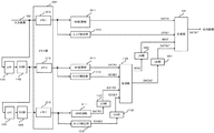
以下、発明の実施形態について図面を参照して詳細に説明する。図1は発明の一実施形態に対応する画像処理装置の構成を示すブロック図であり、特に画像処理ユニットの構成を示している。当該画像処理装置は、例えば、パーソナルコンピュータ、デジタルカメラ、携帯電話、スマートフォン、PDA、タブレット端末などの任意の情報処理装置とすることができる。画像処理装置100の全体構成は例えば図11に示す通りである。
[Embodiment 1]
Hereinafter, embodiments of the invention will be described in detail with reference to the drawings. FIG. 1 is a block diagram showing a configuration of an image processing apparatus corresponding to an embodiment of the invention, and particularly shows a configuration of an image processing unit. The image processing apparatus can be an arbitrary information processing apparatus such as a personal computer, a digital camera, a mobile phone, a smartphone, a PDA, or a tablet terminal. The overall configuration of the
画像処理装置100はCPU101、RAM102、ROM103を有する。ROM103には画像処理装置の基本的な制御プログラムが記憶されている。この制御プログラムは、装置の起動時にRAM102に読み込まれ、CPU101によって実行される。二次記憶装置104は、実際にはハードディスクあるいはメモリディスクなどである。二次記憶装置104には、高レベルな制御プログラム(たとえばオペレーションシステム)、ブラウザ、処理データに関する情報を管理するためのデータベース、機能部105で取得されたデータを装置1000に取り込むためのアプリケーション、取り込まれたデータなどが記憶される。これらのソフトウェアは、適時RAM102に読み込まれ、CPU101によって実行される。
The
機能部105は、装置の種類に応じた特定機能を実行するための構成を有する機能部である。例えば、画像処理装置100がデジタルカメラであれば、画像を撮影するためのカメラ機能を実現するための構成、例えば撮像素子やA/D変換器、画像処理部などが含まれる。ネットワークインタフェース(I/F)106は、外部のネットワークと接続するためのインタフェースである。操作部107は、ユーザからの指示操作を受け付けることが可能であって、キーボード、マウス、ボタン、タッチパネルなどから構成される。表示部108は、CPU101の表示制御に従って画像やグラフィカルユーザインタフェース(GUI)画面を表示し、モニタなどから構成される。そしてバス109は、101〜108が情報をやり取りする際に用いられる。
The
発明の実施形態に対応する画像処理ユニットは、例えば、上記画像処理装置の構成においてCPU101として実現されても良いし、或いは機能部において特定のデータ処理を実現するためのハードウェアとして実現されても良い。例えば、画像処理装置がデジタルカメラである場合、装置に必要な画像処理機能が実装されたハードウェア(専用ロジック回路等)として実現される。以下の説明では、画像処理装置が撮像装置の場合であって、画像処理ユニットが機能部105における画像処理部の一部として実装される場合を説明する。
The image processing unit corresponding to the embodiment of the invention may be realized as, for example, the
機能部105の撮像部(撮像素子やA/D変換器等)から出力された入力画像1000は、メモリ1001に記憶される。メモリ部1001は、メモリ1010、1110及び1210で構成されている。この入力画像1000は、画像処理部における補正部おいて公知のセンサー補正処理が行われた画像データである。また、入力画像1000には、ローパスフィルタ(LPF)1101でLPF処理、ダウンサンプリング(DS)部1102でダウンサンプリング処理が施され、同時化された低解像度画像(第1の低解像度画像)が生成される。なお、同時化とは、同じ画素位置に複数種類の信号が生成されることをいう。
An
生成された第1の低解像度画像はメモリ1110に記憶される。DS部1102から出力された第1の低解像度画像には、LPF1201でLPF処理、DS部1202でダウンサンプリング処理が更に施され、解像度を更に落とした低解像度画像(第2の低解像度画像)が生成される。当該第2の低解像度画像はメモリ1210に記憶される。このようにすることで、処理ステップごとに同時化された低解像度画像が生成される。このような複数段のLPF処理部及びDS部を、画像を低解像度化するための構成として用いることで、解像度レベルが異なる複数の画像を段階的に生成することができる。
The generated first low-resolution image is stored in the
メモリ1010から出力された入力画像はノイズ除去(NR)処理部1011に入力され、本実施形態に対応するNR処理が行われて、NR画像(DATA1)が出力される。また、入力画像は、エッジ検出部1012にも入力され、エッジ検出処理が施される。エッジ検出部1012は、例えば公知のエッジ検出フィルタで構成され、入力信号にエッジ検出フィルタをかけて、その出力を高解像度エッジ強度出力信号(第1のエッジ信号:EDGE1)とする。
The input image output from the
合成部1020は、NR処理部1011から出力されたNR画像(DATA1)と、US部1021から出力されたアップサンプリングされた第2の合成画像(DATA2'')とを第1の合成比率(MIX1)に従って合成する。合成部1020は、第1の合成比率(MIX1)を、エッジ検出部1012の出力である第1のエッジ信号(EDGE1)と、アップサンプリング(US)部1022で、アップサンプリングされた第2の合成比率(MIX2')とに基づいて決定する。合成部1020における合成結果の第1の合成画像は、画像処理ユニットにおける処理結果の出力画像として出力される。
The combining
メモリ1110から出力された第1の低解像度画像はNR処理部1111に入力され、NR処理が行われて、第1の低解像度NR画像(DATA2)が出力される。また、第1の低解像度画像は、エッジ検出部1112にも入力され、エッジ検出処理が施されてエッジ強度出力信号(第2のエッジ信号:EDGE2)が出力される。NR処理部1111及びエッジ検出部1112の機能は、基本的にNR処理部1011及びエッジ検出部1012と同様である。
The first low resolution image output from the
合成部1120は、NR処理部1111から出力された第1の低解像度NR画像(DATA2)と、US部1121でアップサンプリングされた第2の低解像度NR画像(DATA3')とを、第2の合成比率(MIX2)に従って合成する。合成部1120は、第2の合成比率(MIX2)を、エッジ検出部1112の出力である第2のエッジ信号(EDGE2)と、US部1122でアップサンプリングされた第3のエッジ信号(EDGE3')とに基づいて決定する。合成部1120は合成後の第2の合成画像(DATA2')と、合成比率(MIX2)とを出力する。第2の合成画像(DATA2')はUS部1021に入力され、第2の合成比率(MIX2)はUS部1022に入力され、それぞれアップサンプリングされる。
The
メモリ1210から出力された第2の低解像度画像はNR処理部1211に入力され、NR処理が行われて、第2の低解像度NR画像(DATA3)が出力される。また、第2の低解像度画像は、エッジ検出部1212にも入力され、エッジ検出処理が施されてエッジ強度出力信号(第3のエッジ信号:EDGE3)が出力される。NR処理部1211及びエッジ検出部1212の機能は、基本的にNR処理部1011及びエッジ検出部1012と同様である。
The second low-resolution image output from the
なお、ここではエッジ検出部1012は、メモリ1010から出力された入力画像に対してエッジ検出フィルタをかける構成としたが、NR処理部1011から出力されたNR画像(DATA1)に対してエッジ検出フィルタをかける構成としてもよい。これは、エッジ検出部1112とエッジ検出部1212についても同様である。
Here, the
次に、NR処理部1011、1111及び1211におけるノイズ除去処理の詳細を説明する。これらのNR処理部では、画像におけるエッジ情報を保持しつつ、エッジとしては振幅が小さいレベルの信号をノイズとして除去する。図2は、NR処理部におけるノイズ除去処理の一例を示すフローチャートである。ここでは、輝度成分信号をY、色成分信号をU、Vとして説明する。なお、画像の色空間の持たせ方は、YUVに限定されず、YCbCrやYPbPrであっても良いし、RGBであってもよい。当該フローチャートに対応する処理は、機能部105の画像処理部を構成する専用ロジック回路のNR処理部に相当する回路において実施することができるが、それ以外にも、NR処理部として機能するCPU101が対応するプログラム(ROM等に格納)を実行することにより実施しても良い。
Next, details of noise removal processing in the
まずステップS201で、処理対象画像の全画素について画素ごとに色成分信号から以下の式に基づいて彩度信号Cを生成する。 First, in step S201, a saturation signal C is generated from the color component signal for every pixel of the processing target image based on the following equation.
C={U2+V2}1/2 (式1)
次に、ステップS202に進み、処理対象画像を構成する画素の中から注目画素を選択する。さらに、ステップS203において注目画素の彩度信号Ccと、注目画素の周辺画素の彩度信号Ciとの差分絶対値DIFF_Cを算出する。次にステップS204で差分絶対値DIFF_Cと閾値とを比較し、閾値より小さい場合(S204で「YES」)、ステップS205に進む。S205では、差分絶対値が閾値より小さい周辺画素について、平滑化の対象画素とするフラグを立てる。また、差分絶対値DIFF_Cが閾値以上の場合(S204で「NO」)、ステップS206に進む。ステップS206では、注目画素の周辺画素で、差分絶対値を未算出の周辺画素が残っているか否かを判定する。もし、未処理の周辺画素が存在する場合(S206で「YES」)、S203に戻って処理を継続する。ステップS206で未処理の周辺画素がない場合は、ステップS207に進み、ステップS205で平滑化の対象となるフラグを立てた周辺画素を用いて注目画素について平滑化処理を行う。その後、S208に進んで、注目画素として未選択の画素が存在するか否かを判定する。もし未選択の画素が存在する場合(S208で「YES」)、S202に戻って上記処理を繰り返す。全ての画素を注目画素として選択し、上記処理を終えた場合(S208で「NO」)、本処理を終了する。
C = {U 2 + V 2 } 1/2 (Formula 1)
In step S202, the target pixel is selected from the pixels constituting the processing target image. Further, in step S203, the absolute difference value DIFF_C between the saturation signal Cc of the target pixel and the saturation signal Ci of the peripheral pixels of the target pixel is calculated. Next, in step S204, the difference absolute value DIFF_C is compared with a threshold value, and if smaller than the threshold value (“YES” in S204), the process proceeds to step S205. In S205, a flag that is a pixel to be smoothed is set for peripheral pixels having a difference absolute value smaller than the threshold value. If the absolute difference value DIFF_C is greater than or equal to the threshold (“NO” in S204), the process proceeds to step S206. In step S206, it is determined whether or not there are remaining peripheral pixels for which the absolute value of the difference has not yet been calculated in the peripheral pixels of the target pixel. If there is an unprocessed peripheral pixel (“YES” in S206), the process returns to S203 and continues. If there is no unprocessed peripheral pixel in step S206, the process proceeds to step S207, and the smoothing process is performed on the target pixel using the peripheral pixel for which the flag to be smoothed is set in step S205. Thereafter, the process proceeds to S208, and it is determined whether or not there is an unselected pixel as the target pixel. If there is an unselected pixel (“YES” in S208), the process returns to S202 and the above process is repeated. When all the pixels are selected as the target pixel and the above process is completed (“NO” in S208), this process ends.
上記のノイズ除去処理について具体的に図3を例に説明する。図3(A)、(B)に示すように、注目画素(Uc、Vc)を中心として、周辺画素Ui、Vi(i=0〜7)の3x3の領域を平滑化処理対象とする。このとき、i=0、2、6、7の周辺画素が平滑化処理の対象と仮定すると、平滑化処理後の色差信号U_out、V_outは、下記の式2、式3で表現される。 The above noise removal processing will be specifically described with reference to FIG. As shown in FIGS. 3A and 3B, the 3 × 3 region of the peripheral pixels Ui and Vi (i = 0 to 7) with the target pixel (Uc, Vc) as the center is set as a smoothing processing target. At this time, assuming that peripheral pixels of i = 0, 2, 6, and 7 are to be subjected to the smoothing process, the color difference signals U_out and V_out after the smoothing process are expressed by the following expressions 2 and 3.
U_out=(U0+U2+Uc+U6+U7)/5 (式2)
V_out = (V0+V2+Vc+V6+V7)/5 (式3)
なお、図2のフローチャートでは、色成分信号を例としてフローチャートの説明を行ったが、輝度成分信号Yについても同様にNR処理を行う。Y成分については、S201の処理は不要であるため、S202以降の処理を行えばよい。
U_out = (U0 + U2 + Uc + U6 + U7) / 5 (Formula 2)
V_out = (V0 + V2 + Vc + V6 + V7) / 5 (Formula 3)
In the flowchart of FIG. 2, the color component signal is described as an example, but the NR process is similarly performed on the luminance component signal Y. For the Y component, the processing of S201 is unnecessary, and therefore, the processing after S202 may be performed.
図4は、メモリ1010、1110、1210の周波数イメージを示したものである。メモリ1010が格納する入力画像の周波数はf1、メモリ1110が格納する第1の低解像度画像の周波数はf2、メモリ1210が格納する第2の低解像度画像の周波数はf3で表される。このとき、f1>f2>f3が成立する。本実施形態では、合成部を制御して、領域1に属する周波数の画像については、NR処理部1011からの出力の合成比率を高くする。また、領域2に属する周波数の画像については、NR処理部1111からの出力の合成比率を高くする。そして、領域3に属する周波数の画像については、NR処理部1211からの出力の合成比率を高くする。処理対象の画素が、どの領域に属するかについては、エッジ検出結果を示すエッジ信号の値や、合成部1120における合成比率を参照して判定することができる。
FIG. 4 shows frequency images of the
以下、その具体的手法について、合成部1020及び1120における動作の詳細を図5及び図6を参照して説明する。まず図5は、合成部1120における合成処理を説明する図である。図5(A)の横軸はエッジ検出部1112から出力された第2のエッジ信号EDGE2の値を表し、縦軸が合成部1120の第2の合成比率MIX2を表す。ここでは、閾値ThL1及びThL2と比較することによりEDGE2を評価して、第2の合成比率MIX2を決定する。注目画素におけるEDGE2が閾値Th2以上の場合、合成比率は1となり、合成部1120は、注目画素におけるNR処理部1111から出力された第1の低解像度NR画像(DATA2)をそのまま注目画素における第2の合成画像(DATA2')として出力する。注目画素におけるEDGE2が閾値Th1以下の場合、合成比率は0となり、合成部1120は注目画素におけるアップサンプリングされた第2の低解像度NR画像(DATA3')をそのまま注目画素における第2の合成画像(DATA2')として出力する。また、注目画素におけるEDGE2が閾値ThL1とThL2との間の値をとる場合は、以下の式に従って第2の合成比率MIX2が決定される。
Hereinafter, the specific method will be described in detail with reference to FIG. 5 and FIG. First, FIG. 5 is a diagram for explaining the composition process in the
MIX2 =(EDGE2 - ThL1)/(ThL2 - ThL1) (式4)
以上により第2の合成比率MIX2が決定すると、合成部1120からの出力される注目画素における第2の合成画像DATA2'は以下の式に従って決定される。
MIX2 = (EDGE2-ThL1) / (ThL2-ThL1) (Formula 4)
When the second composition ratio MIX2 is determined as described above, the second composite image DATA2 ′ at the target pixel output from the
DATA2'=(DATA2×MIX2)+(DATA3'×(1-MIX2)) (式5)
以上の処理を、合成部1120から出力される第2の合成画像DATA2'に含まれる全ての画素について行う。
DATA2 '= (DATA2 x MIX2) + (DATA3' x (1-MIX2)) (Formula 5)
The above processing is performed for all pixels included in the second composite image DATA2 ′ output from the combining
次に図5(B)は、EDGE2と比較される閾値ThL1とThL2の決定方法の一例を示す。横軸がアップサンプリングされた第3のエッジ信号EDGE3'で、縦軸がEDGE2の閾値ThL1を示す。EDGE3'がThL11以下の場合、閾値ThL1はThL1__maxを出力し、ThL12以上の場合は、閾値ThL1はThL1_Minを出力する。EDGE3'が閾値ThL11とThL12との間の場合は、
ThL1={(ThL1_min - ThL1_max)/(ThL12-ThL11)}*(EDGE3'-ThL11) +ThL1_max (式6)
となる。なお、ThL2の演算もThL1と同様に算出可能であるので説明は省略するが、EDGE3'と閾値ThL21、ThL22とを比較し、ThL2_2maxからThL2_minまでの範囲で値を決定する。なお、ThL22>ThL21、かつ、ThL2_2max > ThL2_min > ThL1_maxである。
Next, FIG. 5B shows an example of a method for determining the threshold values ThL1 and ThL2 to be compared with EDGE2. The horizontal axis is the third edge signal EDGE3 ′ upsampled, and the vertical axis shows the threshold ThL1 of EDGE2. When EDGE3 ′ is equal to or less than ThL11, the threshold ThL1 outputs ThL1__max, and when it is equal to or greater than ThL12, the threshold ThL1 outputs ThL1_Min. If EDGE3 'is between threshold ThL11 and ThL12,
ThL1 = {(ThL1_min-ThL1_max) / (ThL12-ThL11)} * (EDGE3'-ThL11) + ThL1_max (Formula 6)
It becomes. Although the calculation of ThL2 can be calculated in the same manner as ThL1, the description thereof is omitted. However, EDGE3 ′ is compared with threshold values ThL21 and ThL22, and a value is determined in the range from ThL2_2max to ThL2_min. Note that ThL22> ThL21 and ThL2_2max>ThL2_min> ThL1_max.
このように、合成部1120の第2の合成比率MIX2を決定する際に、より低解像度の画像においてもアップサンプリングされた第3のエッジ信号EDGE3'によりエッジであると判定された場合には、EDGE2の判別閾値(ThL1、ThL2)を小さくする。これにより、エッジ判別精度を高めると共に、高解像度の画像の合成比率も高める。このように、よりノイズの影響を受けにくい低解像度画像から検出したエッジ検出結果を利用することで、ノイズとエッジの識別が難しい画像についても、エッジ検出精度を向上することが可能となる。
In this way, when determining the second synthesis ratio MIX2 of the
次に、図6は合成部1020における合成処理を説明する図である。図6(A)の横軸はエッジ検出部1012から出力された第1のエッジ信号EDGE1で、縦軸が合成部1020の第1の合成比率MIX1を示す。ここでは、閾値ThH1及びThH2と比較することによりEDGE1を評価し、第1の合成比率MIX1を決定する。注目画素におけるEDGE1が閾値ThH2以上の場合、第1の合成比率MIX1は1となり、合成部1020は、注目画素におけるNR処理部1011から出力されたNR画像(DATA1)を第1の合成画像(DATA1')として選択し出力する。注目画素におけるEDGE1が閾値ThH1以下の場合、第1の合成比率MIX1は0となり、合成部1020は注目画素におけるアップサンプリングされた第1の低解像度NR画像(DATA2')を第1の合成画像(DATA1')として選択し出力する。また、注目画素におけるEDGE1が閾値ThH1とThH2との間の値をとる場合は、以下の式に従って第1の合成比率MIX1が決定される。
Next, FIG. 6 is a diagram for explaining the composition processing in the
MIX1 =(EDGE1 - ThH1)/(ThH2 - ThH1) (式7)
第1の合成比率MIX1が決定すると、合成部1020から出力される注目画素における第1の合成画像(DATA1')は以下の式に従って決定される。
MIX1 = (EDGE1-ThH1) / (ThH2-ThH1) (Formula 7)
When the first composition ratio MIX1 is determined, the first composite image (DATA1 ′) in the target pixel output from the
DATA1'=(DATA1×MIX1)+(DATA2"×(1-MIX1)) (式8)
以上の処理を、合成部1020から出力される第1の合成画像DATA1'に含まれる全ての画素について行う。
DATA1 '= (DATA1 x MIX1) + (DATA2 "x (1-MIX1)) (Formula 8)
The above processing is performed for all the pixels included in the first composite image DATA1 ′ output from the combining
また、図6(B)は、EDGE1と比較される閾値ThH1とThH2の決定方法の一例を示す。横軸がUS部1022でアップサンプリングされた第2の合成比率MIX2'で、縦軸がエッジ検出の閾値ThH1を示す。MIX2'信号が1の場合、閾値ThH1はThH1_minを出力し、MIX2'信号が0の場合、閾値ThH1はThH1_maxを出力する。MIX2'信号が0と1との間の値をとる場合は、以下の式に従って閾値ThH1を決定する。
FIG. 6B shows an example of a method for determining threshold values ThH1 and ThH2 to be compared with EDGE1. The horizontal axis represents the second composite ratio MIX2 ′ upsampled by the
ThH1=(ThH1_min - ThH1_max)*(MIX2') +ThH1_max (式9)
なお、閾値ThH2の演算もThH1と同様に算出可能であるので説明は省略するが、MIX2'と閾値ThH21、ThH22とを比較し、ThH2_2maxからThH2_minまでの範囲で値を決定する。なお、ThH22>ThH21、かつ、ThH2_2max > ThH2_min > ThH1_maxである。
ThH1 = (ThH1_min-ThH1_max) * (MIX2 ') + ThH1_max (Equation 9)
Although the calculation of the threshold ThH2 can be calculated in the same manner as ThH1, the description thereof is omitted, but MIX2 ′ is compared with the thresholds ThH21 and ThH22, and the value is determined in the range from ThH2_2max to ThH2_min. Note that ThH22> ThH21 and ThH2_2max>ThH2_min> ThH1_max.
このように、合成部1020の合成比率を決定する際に、MIX2'が大きい(エッジ成分が多い)と判定された場合、EDGE1の判別閾値(ThH1、ThH2)を小さくして、エッジ判別精度を高くする。また、これにより高解像度画像の合成比率を高くすることができる。このように、本実施形態では、よりノイズの影響を受けにくい低解像度画像について得られた合成比率を、画像のエッジ成分に関する指標として利用する。これにより、ノイズとエッジの識別が難しい画像においても、エッジ検出精度を向上することが可能となる。
In this way, when determining the composition ratio of the
上記説明したように、本実施形態では、低解像度画像から求めたエッジ検出結果及び合成比率と、高解像度画像のエッジ検出結果とを参照して、高解像度画像の合成比率を決定する。これにより、ノイズとエッジの識別が難しい画像であっても、エッジ検出精度を向上させることができる。よって、エッジ成分の多い画像については、高解像度の画像の合成比率を高めてエッジ情報を残存させる一方、エッジ成分が少ない画像については低解像度の画像の合成比率を高めてノイズ成分を低減させることができる。 As described above, in the present embodiment, the synthesis ratio of the high resolution image is determined with reference to the edge detection result and synthesis ratio obtained from the low resolution image and the edge detection result of the high resolution image. As a result, even if the image is difficult to distinguish between noise and edge, the edge detection accuracy can be improved. Therefore, for images with a lot of edge components, the synthesis ratio of high-resolution images is increased to leave edge information, while for images with few edge components, the synthesis ratio of low-resolution images is increased to reduce noise components. Can do.
なお、本実施形態において、低解像度画像のエッジ検出の結果または合成比率を参照して、エッジ検出の閾値(ThL1、ThL2、ThH1、ThH2)を変更する方法を用いて説明した。しかし、低解像度画像におけるエッジ検出結果や合成比率を合成比率に反映させるものであれば、方法はこれに限るものでない。 In the present embodiment, the edge detection threshold (ThL1, ThL2, ThH1, ThH2) has been described with reference to the edge detection result or the composition ratio of the low resolution image. However, the method is not limited to this as long as the edge detection result and the composition ratio in the low-resolution image are reflected in the composition ratio.
[実施形態2]
次に、発明の第2の実施形態を説明する。図7は発明の一実施形態に対応する画像処理装置の構成を示すブロック図であり、特に画像処理ユニットの構成を示している。本実施形態においても、画像処理装置の全体的な構成は図1と同様であり、以下、画像処理装置が撮像装置の場合であって、画像処理ユニットが機能部105における画像処理部の一部として実装される場合を説明する。但し、実施形態1と共通する点については説明を省略し、異なる点について主に説明する。なお、図7において、図1に対応する構成要素に対しては同一の参照番号を付している。
[Embodiment 2]
Next, a second embodiment of the invention will be described. FIG. 7 is a block diagram showing a configuration of an image processing apparatus corresponding to an embodiment of the invention, and particularly shows a configuration of an image processing unit. Also in this embodiment, the overall configuration of the image processing apparatus is the same as that in FIG. 1. Hereinafter, the image processing apparatus is an imaging apparatus, and the image processing unit is a part of the image processing unit in the
メモリ1010から出力された入力画像はノイズ除去(NR)処理部7011に入力され、本実施形態に対応するNR処理が行われて、NR画像(DATA1)が出力される。合成部7020は、NR処理部7011から出力されたNR画像(DATA1)と、アップサンプリング(US)部1021から出力されたアップサンプリングされた第2の合成画像(DATA2'')とを合成する。当該合成は、エッジ検出部1012の出力である第1のエッジ信号(EDGE1)に基づき決定される第1の合成比率(MIX1)に従って行う。合成部1020における合成結果の第1の合成画像は、画像処理ユニットにおける処理結果の出力画像として出力される。
The input image output from the
次に、メモリ1110からの出力された第1の低解像度画像はNR処理部7111に入力され、本実施形態に対応するNR処理が行われ、第1の低解像度NR画像(DATA2)が出力される。また、第1の低解像度画像は、エッジ検出部1112にも入力され、第2のエッジ信号(EDGE2)が生成される。
Next, the first low-resolution image output from the
合成部7120は、NR処理部7111から出力された第1の低解像度NR画像(DATA2)と、US部1121でアップサンプリングされた第2の低解像度NR画像(DATA3')とを合成する。当該合成は、エッジ検出部1112の出力である第2のエッジ信号(EDGE2)に基づき合成比率(MIX2)を決定して行う。
The
合成部7120は合成結果の第2の合成画像(DATA2')と第2の合成比率(MIX2)とを出力する。第2の合成画像(DATA2')はUS部1021に入力され、第2の合成比率(MIX2)はUS部1022に入力され、それぞれアップサンプリングされる。US部1022でアップサンプリングされた第2の合成比率(MIX2')は、NR処理部7011に入力される。
The
メモリ1210から出力された第2の低解像度画像はNR処理部1211に入力され、NR処理が行われて、第2の低解像度NR画像(DATA3)が出力される。また、第2の低解像度画像は、エッジ検出部1212にも入力され、第3のエッジ信号(EDGE3)が生成される。出力された第3のエッジ信号は、US部1122でアップサンプリングされて、NR処理部7111に入力される。
The second low-resolution image output from the
次に、NR処理部7011及び7111におけるノイズ除去処理の詳細を説明する。図8は、NR処理部におけるノイズ除去処理の一例を示すフローチャートである。当該フローチャートに対応する処理は、機能部105の画像処理部を構成する専用ロジック回路のNR処理部に相当する回路において実施することができるが、それ以外にも、NR処理部として機能するCPU101が対応するプログラム(ROM等に格納)を実行することにより実施しても良い。
Next, details of noise removal processing in the
ステップS801で、後段のステップS804の処理で使用する閾値の設定を行う。ここでの閾値設定の方法の一例を図9、図10を参照して説明する。図9は、NR処理部7111における閾値設定方法の一例を説明する図である。図9において、横軸はアップサンプリングされた第3のエッジ信号EDGE3'を表し、縦軸はノイズ除去処理用の閾値NRThの値を表す。本実施形態では、閾値NRThは、NRTh__maxからNRTh__minまでの値をとる。EDGE3'の値を閾値ThN11及びThN12と比較し、ThN11以下の場合、閾値NRThをNRTh__maxに決定する。一方、EDGE3'がThN12以上の場合、閾値NRThをNRTh_minに決定する。EDGE3'が閾値ThN11とThN12との間の場合は、以下の式に従って閾値NRThを決定する。 In step S801, a threshold value used in the processing in the subsequent step S804 is set. An example of the threshold setting method here will be described with reference to FIGS. FIG. 9 is a diagram for explaining an example of a threshold setting method in the NR processing unit 7111. In FIG. 9, the horizontal axis represents the up-sampled third edge signal EDGE3 ′, and the vertical axis represents the value of the threshold value NRTh for noise removal processing. In the present embodiment, the threshold value NRTh takes a value from NRTh__max to NRTh__min. The value of EDGE3 ′ is compared with threshold values ThN11 and ThN12, and when it is equal to or less than ThN11, the threshold value NRTh is determined to be NRTh__max. On the other hand, when EDGE3 ′ is equal to or greater than ThN12, the threshold NRTh is determined to be NRTh_min. When EDGE3 ′ is between the threshold values ThN11 and ThN12, the threshold value NRTh is determined according to the following equation.
NRTh={(NRTh_min - NRTh_max)/(ThN12-ThN11)}*(EDGE3' - ThN11) +NRTh_max (式10)
次に、図10は、NR処理部7011における閾値設定方法の一例を説明する図である。図10において、横軸はUS部1022でアップサンプリングされた第2の合成比率MIX2'を表し、縦軸はノイズ除去処理用の閾値NRTHの値を表す。本実施形態では、閾値NRTHは、NRTh__maxからNRTh__minまでの値をとる。ここではMIX2'が0の場合、閾値NRThをNRTh__maxに決定し、1の場合、閾値NRThをNRTh_minに決定する。MIX2'が0と1との間の場合は、以下の式に従って閾値NRThを決定する。
NRTh = {(NRTh_min−NRTh_max) / (ThN12−ThN11)} * (EDGE3′−ThN11) + NRTh_max (Formula 10)
Next, FIG. 10 is a diagram illustrating an example of a threshold setting method in the
NRTh=(NRTh_min - NRTh_max)*MIX2'+NRTh_max (式11)
再び図8の説明に戻り、S801で閾値が決定すると、S802で、処理対象画像の全画素について画素ごとに色成分信号から式1に基づいて彩度信号Cを生成する。S802以降S809までの処理は、図2のS201からS208と同様であるので、詳細な説明は省略する。
NRTh = (NRTh_min-NRTh_max) * MIX2 '+ NRTh_max (Formula 11)
Returning to the description of FIG. 8 again, when the threshold value is determined in S801, the saturation signal C is generated based on
なお、本実施形態では、NR処理部において前段のエッジ検出結果や合成比率を考慮したノイズ除去処理を行っているので、合成部1120及び1020では、これらを考慮しなくても良い。即ち、図5(B)や図6(B)における閾値ThL1、ThL2、ThH1及びThH2の決定処理を省略し、各閾値を固定とすることができる。その場合、合成対象の画像については、画像に含まれるエッジ成分量に応じたノイズ除去処理が行われているので、エッジ判別精度が高くなるように、各閾値を小さく設定することができる。例えば、ThL1=ThL1_min、ThL2=ThL2_min、ThH1=ThH1_min、及び、ThH2=ThH2_minとすることができる。
In the present embodiment, since the noise removal processing is performed in consideration of the previous edge detection result and the synthesis ratio in the NR processing unit, the
以上のように、NR処理部においてノイズ除去処理を行う際に、注目画素と周辺画素との差分絶対値と比較される閾値を、低解像度画像におけるエッジ検出結果や合成比率に基づいて決定しノイズ除去の度合いを制御することができる。これにより、例えば、第2の低解像度画像におけるエッジ検出結果に基づくアップサンプリングされた第2のエッジ信号EDGE3で、エッジ成分が多いと判断される場合は、NR処理の閾値が小さくなる。この結果、平滑化処理に利用される周辺画素数が減り、第1の低解像度画像に対するNR処理効果が弱められ、画像におけるエッジ成分が維持されることになる。一方、第2のエッジ信号EDGE3からエッジ成分が少ないと判断される場合は、NR処理の閾値を大きくする。この結果、より多くの周辺画素を用いた平滑化処理がお壊れることになるので第1の低解像度画像に対するノイズ除去効果を高めた上で、合成処理を実行することができる。 As described above, when the noise removal process is performed in the NR processing unit, the threshold value to be compared with the absolute difference value between the target pixel and the surrounding pixels is determined based on the edge detection result and the composition ratio in the low-resolution image, and the noise. The degree of removal can be controlled. Thereby, for example, when it is determined that there are many edge components in the second edge signal EDGE3 upsampled based on the edge detection result in the second low-resolution image, the threshold value of the NR process is decreased. As a result, the number of peripheral pixels used for the smoothing process is reduced, the NR processing effect on the first low-resolution image is weakened, and the edge component in the image is maintained. On the other hand, if it is determined from the second edge signal EDGE3 that there are few edge components, the threshold for NR processing is increased. As a result, the smoothing process using more peripheral pixels is broken, so that the synthesis process can be executed after enhancing the noise removal effect for the first low-resolution image.
また、例えば合成部1120における合成比率MIX2において、第1の低解像度NR画像の合成比率が高いと判断される場合、NR処理の閾値が小さくなる。この結果、入力画像に対するNR処理効果が弱められ、画像におけるエッジ成分が維持されることになる。一方、第1の低解像度NR画像の合成比率が低いと判断される場合、NR処理の閾値を大きくする。この結果、入力画像に対するノイズ除去効果を高めた上で、合成処理を実行することができる。
For example, when it is determined that the composition ratio of the first low-resolution NR image is high in the composition ratio MIX2 in the
以上のように、本実施形態によれば、低解像度画像から求めたエッジ検出結果や合成比率を参照して、処理対象の画像に含まれるエッジ成分が多いと判断される場合、高解像度画像のNR処理部の効果を弱くしてエッジ情報を維持することができる。これにより、ノイズとエッジの識別が難しい画像であっても、ノイズとエッジの検出精度を向上することが可能となる。 As described above, according to the present embodiment, when it is determined that there are many edge components included in the processing target image with reference to the edge detection result and the synthesis ratio obtained from the low resolution image, the high resolution image Edge information can be maintained by weakening the effect of the NR processing unit. This makes it possible to improve noise and edge detection accuracy even for images that are difficult to distinguish between noise and edges.
本実施形態でも、低解像度画像のエッジ検出結果や合成比率を参照して、NR処理部の閾値(Th1、Th2)を変更する方法を用いて説明した。しかし、低解像度画像のエッジ検出の結果または合成比率をNR処理部に反映させるものであれば、方法はこれに限るものでない。 Also in the present embodiment, the description has been given using the method of changing the threshold values (Th1, Th2) of the NR processing unit with reference to the edge detection result and the composition ratio of the low resolution image. However, the method is not limited to this as long as the result of edge detection or the composition ratio of the low resolution image is reflected in the NR processing unit.
(その他の実施例)
また、本発明は、以下の処理を実行することによっても実現される。即ち、上述した実施形態の機能を実現するソフトウェア(プログラム)を、ネットワーク又は各種記憶媒体を介してシステム或いは装置に供給し、そのシステム或いは装置のコンピュータ(またはCPUやMPU等)がプログラムを読み出して実行する処理である。
(Other examples)
The present invention can also be realized by executing the following processing. That is, software (program) that realizes the functions of the above-described embodiments is supplied to a system or apparatus via a network or various storage media, and a computer (or CPU, MPU, or the like) of the system or apparatus reads the program. It is a process to be executed.
Claims (17)
前記入力画像を段階的に低解像度化する低解像度化手段と、
前記低解像度化手段により段階的に低解像度化して得られた、解像度レベルの異なる複数の低解像度画像を、各低解像度画像に含まれるエッジ成分の大きさに応じた第2の合成比率に基づき合成して第2の合成画像を生成する第1の合成手段と、
前記入力画像に含まれるエッジ成分の大きさと前記第2の合成比率とに基づく前記第1の合成比率に基づき、前記入力画像と前記第2の合成画像とを合成し、前記第1の合成画像を生成する第2の合成手段と
を備えることを特徴とする画像処理装置。 An image processing device that combines an input image and a low-resolution image obtained from the input image based on a first combining ratio to generate a first combined image,
A resolution reducing means for reducing the resolution of the input image stepwise;
A plurality of low resolution images having different resolution levels obtained by reducing the resolution stepwise by the resolution reducing means are based on a second composition ratio corresponding to the size of the edge component included in each low resolution image. First combining means for combining and generating a second combined image;
Based on the first composition ratio based on the size of the edge component included in the input image and the second composition ratio, the input image and the second composition image are composed, and the first composite image And a second synthesizing unit for generating the image processing apparatus.
前記第2の合成手段は、前記入力画像に含まれる前記エッジ成分の大きさを、前記第2の合成比率における前記第1の低解像度画像の合成比率の大きさに応じた第1の閾値との比較に基づき評価して、前記第1の合成比率を決定することを特徴とする請求項1に記載の画像処理装置。 The first synthesizing unit synthesizes the first low-resolution image obtained by the resolution-reducing unit and a second low-resolution image having a lower resolution than the first low-resolution image,
The second synthesizing unit sets a size of the edge component included in the input image to a first threshold value according to a synthesis ratio of the first low-resolution image in the second synthesis ratio. The image processing apparatus according to claim 1, wherein the first synthesis ratio is determined based on an evaluation based on a comparison between the first and second synthesis ratios.
前記入力画像を段階的に低解像度化する低解像度化手段と、
前記入力画像からノイズ除去する第1の除去手段と、
前記低解像度化手段により段階的に低解像度化して得られた、第1の低解像度画像と、前記第1の低解像度画像よりも解像度の低い第2の低解像度画像とからノイズ除去する第2の除去手段と、
前記ノイズ除去された前記第1の低解像度画像と前記第2の低解像度画像とを、前記第1の低解像度画像に含まれるエッジ成分の大きさに応じた第2の合成比率に基づき合成して第2の合成画像を生成する第1の合成手段と、
前記ノイズ除去された入力画像に含まれるエッジ成分の大きさに基づく前記第1の合成比率に基づき、前記ノイズ除去された入力画像と前記第2の合成画像とを合成し、前記第1の合成画像を生成する第2の合成手段と
を備え、
前記第1の除去手段は、前記第2の合成比率に応じたノイズ除去の度合いにより、前記入力画像からノイズ除去を行うことを特徴とする画像処理装置。 An image processing device that combines an input image and a low-resolution image obtained from the input image based on a first combining ratio to generate a first combined image,
A resolution reducing means for reducing the resolution of the input image stepwise;
First removing means for removing noise from the input image;
A second noise is removed from the first low-resolution image obtained by reducing the resolution stepwise by the resolution-reducing means and the second low-resolution image having a resolution lower than that of the first low-resolution image. Removal means,
The noise-removed first low-resolution image and second low-resolution image are synthesized based on a second synthesis ratio corresponding to the size of an edge component included in the first low-resolution image. First combining means for generating a second combined image;
Based on the first synthesis ratio based on the size of the edge component included in the input image from which noise has been removed, the input image from which noise has been removed and the second synthesized image are synthesized, and the first synthesis is performed. Second combining means for generating an image,
The image processing apparatus according to claim 1, wherein the first removal unit removes noise from the input image according to a degree of noise removal corresponding to the second synthesis ratio.
注目画素と周辺画素との差分絶対値が、前記第2の合成比率における前記第1の低解像度画像の合成比率の大きさに応じた第1の閾値よりも小さくなる周辺画素と、
前記注目画素と
を用いた平滑化処理により、前記ノイズ除去を行うことを特徴とする請求項8に記載の画像処理装置。 It said first removal means, among the pixels included in the input image,
A peripheral pixel in which a difference absolute value between a target pixel and a peripheral pixel is smaller than a first threshold corresponding to a size of a composite ratio of the first low-resolution image in the second composite ratio;
The image processing apparatus according to claim 8, wherein the noise removal is performed by a smoothing process using the target pixel.
注目画素と周辺画素との差分絶対値が、前記第2の低解像度画像に含まれるエッジ成分の大きさに応じた第2の閾値よりも小さくなる周辺画素と、
前記注目画素と
を用いた平滑化処理により、前記ノイズ除去を行うことを特徴とする請求項11に記載の画像処理装置。 Said second removal means, out of the pixels included in the first low-resolution images,
A peripheral pixel in which a difference absolute value between the target pixel and the peripheral pixel is smaller than a second threshold corresponding to a size of an edge component included in the second low-resolution image;
The image processing apparatus according to claim 11, wherein the noise removal is performed by a smoothing process using the target pixel.
前記入力画像を段階的に低解像度化する低解像度化工程と、
前記低解像度化工程において段階的に低解像度化して得られた、解像度レベルの異なる複数の低解像度画像を、各低解像度画像に含まれるエッジ成分の大きさに応じた第2の合成比率に基づき合成して第2の合成画像を生成する第1の合成工程と、
前記入力画像に含まれるエッジ成分の大きさと前記第2の合成比率とに基づく前記第1の合成比率に基づき、前記入力画像と前記第2の合成画像とを合成し、前記第1の合成画像を生成する第2の合成工程と
を備えることを特徴とする画像処理装置の制御方法。 A control method for an image processing apparatus that combines an input image and a low resolution image obtained from the input image based on a first combining ratio to generate a first combined image,
A resolution reduction step of gradually reducing the resolution of the input image;
A plurality of low-resolution images having different resolution levels obtained by reducing the resolution stepwise in the resolution-reducing step are based on a second synthesis ratio corresponding to the size of the edge component included in each low-resolution image. A first combining step of combining and generating a second combined image;
Based on the first composition ratio based on the size of the edge component included in the input image and the second composition ratio, the input image and the second composition image are composed, and the first composite image And a second synthesizing step for generating the image processing apparatus.
前記入力画像を段階的に低解像度化する低解像度化工程と、
前記入力画像からノイズ除去する第1の除去工程と、
前記低解像度化工程において段階的に低解像度化して得られた、第1の低解像度画像と、前記第1の低解像度画像よりも解像度の低い第2の低解像度画像とからノイズ除去する第2の除去工程と、
前記ノイズ除去された前記第1の低解像度画像と前記第2の低解像度画像とを、前記第1の低解像度画像に含まれるエッジ成分の大きさに応じた第2の合成比率に基づき合成して第2の合成画像を生成する第1の合成工程と、
前記ノイズ除去された入力画像に含まれるエッジ成分の大きさに基づく前記第1の合成比率に基づき、前記ノイズ除去された入力画像と前記第2の合成画像とを合成し、前記第1の合成画像を生成する第2の合成工程と
を備え、
前記第1の除去工程では、前記第2の合成比率に応じたノイズ除去の度合いにより、前記入力画像からノイズ除去が行われることを特徴とする画像処理装置の制御方法。 A control method for an image processing apparatus that combines an input image and a low resolution image obtained from the input image based on a first combining ratio to generate a first combined image,
A resolution reduction step of gradually reducing the resolution of the input image;
A first removal step of removing noise from the input image;
A second noise removal is performed from the first low-resolution image obtained by reducing the resolution stepwise in the resolution-reducing step and the second low-resolution image having a lower resolution than the first low-resolution image. Removing process of
The noise-removed first low-resolution image and second low-resolution image are synthesized based on a second synthesis ratio corresponding to the size of an edge component included in the first low-resolution image. A first combining step for generating a second combined image;
Based on the first synthesis ratio based on the size of the edge component included in the input image from which noise has been removed, the input image from which noise has been removed and the second synthesized image are synthesized, and the first synthesis is performed. A second synthesis step for generating an image,
In the first removal step, noise is removed from the input image according to the degree of noise removal according to the second synthesis ratio.
Priority Applications (1)
| Application Number | Priority Date | Filing Date | Title |
|---|---|---|---|
| JP2013250552A JP6242196B2 (en) | 2013-12-03 | 2013-12-03 | Image processing apparatus, image processing apparatus control method, and program |
Applications Claiming Priority (1)
| Application Number | Priority Date | Filing Date | Title |
|---|---|---|---|
| JP2013250552A JP6242196B2 (en) | 2013-12-03 | 2013-12-03 | Image processing apparatus, image processing apparatus control method, and program |
Publications (3)
| Publication Number | Publication Date |
|---|---|
| JP2015108897A JP2015108897A (en) | 2015-06-11 |
| JP2015108897A5 JP2015108897A5 (en) | 2017-01-19 |
| JP6242196B2 true JP6242196B2 (en) | 2017-12-06 |
Family
ID=53439216
Family Applications (1)
| Application Number | Title | Priority Date | Filing Date |
|---|---|---|---|
| JP2013250552A Expired - Fee Related JP6242196B2 (en) | 2013-12-03 | 2013-12-03 | Image processing apparatus, image processing apparatus control method, and program |
Country Status (1)
| Country | Link |
|---|---|
| JP (1) | JP6242196B2 (en) |
Families Citing this family (2)
| Publication number | Priority date | Publication date | Assignee | Title |
|---|---|---|---|---|
| CN108595220B (en) * | 2018-04-25 | 2021-04-16 | 上海掌门科技有限公司 | Application component processing method and device and computer readable storage medium |
| JP2023103116A (en) * | 2022-01-13 | 2023-07-26 | Tvs Regza株式会社 | image processing circuit |
Family Cites Families (3)
| Publication number | Priority date | Publication date | Assignee | Title |
|---|---|---|---|---|
| JP2008165312A (en) * | 2006-12-27 | 2008-07-17 | Konica Minolta Holdings Inc | Image processor and image processing method |
| EP2536152B1 (en) * | 2010-02-12 | 2018-09-05 | Canon Kabushiki Kaisha | Image processing device and image processing method |
| JP5719148B2 (en) * | 2010-11-10 | 2015-05-13 | キヤノン株式会社 | Imaging apparatus, control method therefor, and program |
-
2013
- 2013-12-03 JP JP2013250552A patent/JP6242196B2/en not_active Expired - Fee Related
Also Published As
| Publication number | Publication date |
|---|---|
| JP2015108897A (en) | 2015-06-11 |
Similar Documents
| Publication | Publication Date | Title |
|---|---|---|
| US7613363B2 (en) | Image superresolution through edge extraction and contrast enhancement | |
| US9262684B2 (en) | Methods of image fusion for image stabilization | |
| JP6635799B2 (en) | Image processing apparatus, image processing method, and program | |
| JP5609080B2 (en) | Image processing apparatus, image display apparatus, image processing program, and image processing method | |
| JP6369150B2 (en) | Filtering method and filtering apparatus for recovering anti-aliasing edge | |
| JPWO2015190136A1 (en) | Image processing system and program | |
| JP6242196B2 (en) | Image processing apparatus, image processing apparatus control method, and program | |
| CN109325909B (en) | Image amplification method and image amplification device | |
| KR20220153657A (en) | Directional scaling systems and methods | |
| EP3125191A1 (en) | Image processing device | |
| KR102470242B1 (en) | Image processing device, image processing method and program | |
| US11580620B2 (en) | Image processing apparatus, image processing method, and non-transitory computer-readable medium | |
| JP2019100937A (en) | Defect inspection device and defect inspection method | |
| JP6344651B2 (en) | Imaging device with focus assist function | |
| JP2008021219A (en) | Image processing apparatus and method | |
| US9552632B2 (en) | Dynamic waveform region enhancement | |
| KR20200080926A (en) | Display apparatus and image processing method thereof | |
| JP5350497B2 (en) | Motion detection device, control program, and integrated circuit | |
| US11778240B2 (en) | Banding artifact detection in images and videos | |
| EP3719740B1 (en) | Image processing device, image processing method, and image processing program | |
| US10096090B2 (en) | Image processing apparatus, image processing method, and storage medium, relating to emphasizing a contour region | |
| JP5804258B2 (en) | Image processing device, electronic equipment | |
| JP2016174306A (en) | Image processing apparatus, screen processing method and program | |
| JP5701816B2 (en) | Image processing apparatus, image processing program, and image processing method | |
| JP2014178742A (en) | Image processor, image processing method and image processing program |
Legal Events
| Date | Code | Title | Description |
|---|---|---|---|
| A521 | Request for written amendment filed |
Free format text: JAPANESE INTERMEDIATE CODE: A523 Effective date: 20161205 |
|
| A621 | Written request for application examination |
Free format text: JAPANESE INTERMEDIATE CODE: A621 Effective date: 20161205 |
|
| A977 | Report on retrieval |
Free format text: JAPANESE INTERMEDIATE CODE: A971007 Effective date: 20170928 |
|
| TRDD | Decision of grant or rejection written | ||
| A01 | Written decision to grant a patent or to grant a registration (utility model) |
Free format text: JAPANESE INTERMEDIATE CODE: A01 Effective date: 20171010 |
|
| A61 | First payment of annual fees (during grant procedure) |
Free format text: JAPANESE INTERMEDIATE CODE: A61 Effective date: 20171107 |
|
| R151 | Written notification of patent or utility model registration |
Ref document number: 6242196 Country of ref document: JP Free format text: JAPANESE INTERMEDIATE CODE: R151 |
|
| LAPS | Cancellation because of no payment of annual fees |