JP6240163B2 - Cartridge for supplying fluid - Google Patents
Cartridge for supplying fluid Download PDFInfo
- Publication number
- JP6240163B2 JP6240163B2 JP2015510659A JP2015510659A JP6240163B2 JP 6240163 B2 JP6240163 B2 JP 6240163B2 JP 2015510659 A JP2015510659 A JP 2015510659A JP 2015510659 A JP2015510659 A JP 2015510659A JP 6240163 B2 JP6240163 B2 JP 6240163B2
- Authority
- JP
- Japan
- Prior art keywords
- conduit
- pump chamber
- fluid
- reservoir
- plunger
- Prior art date
- Legal status (The legal status is an assumption and is not a legal conclusion. Google has not performed a legal analysis and makes no representation as to the accuracy of the status listed.)
- Active
Links
- 239000012530 fluid Substances 0.000 title claims description 323
- 238000000034 method Methods 0.000 claims description 26
- 239000012472 biological sample Substances 0.000 claims description 16
- 238000005086 pumping Methods 0.000 claims description 16
- 230000008859 change Effects 0.000 claims description 7
- 238000004891 communication Methods 0.000 claims description 2
- 230000005499 meniscus Effects 0.000 description 61
- 238000003860 storage Methods 0.000 description 53
- 230000033001 locomotion Effects 0.000 description 30
- 238000005259 measurement Methods 0.000 description 23
- 239000003153 chemical reaction reagent Substances 0.000 description 21
- 230000009286 beneficial effect Effects 0.000 description 19
- 230000008878 coupling Effects 0.000 description 17
- 238000010168 coupling process Methods 0.000 description 17
- 238000005859 coupling reaction Methods 0.000 description 17
- 238000004458 analytical method Methods 0.000 description 15
- 230000006870 function Effects 0.000 description 14
- 239000007788 liquid Substances 0.000 description 12
- 239000012528 membrane Substances 0.000 description 10
- 238000013461 design Methods 0.000 description 9
- 238000010586 diagram Methods 0.000 description 9
- 230000007246 mechanism Effects 0.000 description 8
- 239000002245 particle Substances 0.000 description 8
- 230000008569 process Effects 0.000 description 8
- 230000009471 action Effects 0.000 description 7
- 238000012360 testing method Methods 0.000 description 7
- 230000008901 benefit Effects 0.000 description 6
- 230000037452 priming Effects 0.000 description 6
- 230000000712 assembly Effects 0.000 description 5
- 238000000429 assembly Methods 0.000 description 5
- 230000003287 optical effect Effects 0.000 description 5
- 239000002699 waste material Substances 0.000 description 5
- 229920000049 Carbon (fiber) Polymers 0.000 description 4
- 238000005481 NMR spectroscopy Methods 0.000 description 4
- 241000289371 Ornithorhynchus anatinus Species 0.000 description 4
- 241000700605 Viruses Species 0.000 description 4
- 230000005540 biological transmission Effects 0.000 description 4
- 239000004917 carbon fiber Substances 0.000 description 4
- 239000003085 diluting agent Substances 0.000 description 4
- 238000003018 immunoassay Methods 0.000 description 4
- 239000004816 latex Substances 0.000 description 4
- 229920000126 latex Polymers 0.000 description 4
- 239000006249 magnetic particle Substances 0.000 description 4
- 238000004519 manufacturing process Methods 0.000 description 4
- VNWKTOKETHGBQD-UHFFFAOYSA-N methane Chemical compound C VNWKTOKETHGBQD-UHFFFAOYSA-N 0.000 description 4
- 238000003752 polymerase chain reaction Methods 0.000 description 4
- 229920001343 polytetrafluoroethylene Polymers 0.000 description 4
- 239000004810 polytetrafluoroethylene Substances 0.000 description 4
- 239000008280 blood Substances 0.000 description 3
- 210000004369 blood Anatomy 0.000 description 3
- 230000003247 decreasing effect Effects 0.000 description 3
- 239000011796 hollow space material Substances 0.000 description 3
- 239000000203 mixture Substances 0.000 description 3
- 230000003068 static effect Effects 0.000 description 3
- 238000013519 translation Methods 0.000 description 3
- OKTJSMMVPCPJKN-UHFFFAOYSA-N Carbon Chemical compound [C] OKTJSMMVPCPJKN-UHFFFAOYSA-N 0.000 description 2
- 102000004190 Enzymes Human genes 0.000 description 2
- 108090000790 Enzymes Proteins 0.000 description 2
- 102000007056 Recombinant Fusion Proteins Human genes 0.000 description 2
- 108010008281 Recombinant Fusion Proteins Proteins 0.000 description 2
- 239000002253 acid Substances 0.000 description 2
- 239000000853 adhesive Substances 0.000 description 2
- 230000001070 adhesive effect Effects 0.000 description 2
- 239000011324 bead Substances 0.000 description 2
- 239000002041 carbon nanotube Substances 0.000 description 2
- 229910021393 carbon nanotube Inorganic materials 0.000 description 2
- 238000006243 chemical reaction Methods 0.000 description 2
- 238000004587 chromatography analysis Methods 0.000 description 2
- 230000000994 depressogenic effect Effects 0.000 description 2
- 239000003599 detergent Substances 0.000 description 2
- 239000006185 dispersion Substances 0.000 description 2
- 230000000694 effects Effects 0.000 description 2
- 239000000835 fiber Substances 0.000 description 2
- 229920002313 fluoropolymer Polymers 0.000 description 2
- 239000004811 fluoropolymer Substances 0.000 description 2
- 230000002209 hydrophobic effect Effects 0.000 description 2
- 238000001746 injection moulding Methods 0.000 description 2
- 235000021056 liquid food Nutrition 0.000 description 2
- 229910001338 liquidmetal Inorganic materials 0.000 description 2
- 239000002105 nanoparticle Substances 0.000 description 2
- 102000039446 nucleic acids Human genes 0.000 description 2
- 108020004707 nucleic acids Proteins 0.000 description 2
- 150000007523 nucleic acids Chemical class 0.000 description 2
- 239000004033 plastic Substances 0.000 description 2
- 229920005594 polymer fiber Polymers 0.000 description 2
- -1 polytetrafluoroethylene Polymers 0.000 description 2
- 102000004169 proteins and genes Human genes 0.000 description 2
- 108090000623 proteins and genes Proteins 0.000 description 2
- 150000003839 salts Chemical class 0.000 description 2
- 229910000679 solder Inorganic materials 0.000 description 2
- 239000002904 solvent Substances 0.000 description 2
- 239000000126 substance Substances 0.000 description 2
- 239000000725 suspension Substances 0.000 description 2
- 238000003856 thermoforming Methods 0.000 description 2
- 238000012546 transfer Methods 0.000 description 2
- 238000009423 ventilation Methods 0.000 description 2
- XLYOFNOQVPJJNP-UHFFFAOYSA-N water Substances O XLYOFNOQVPJJNP-UHFFFAOYSA-N 0.000 description 2
- 230000006399 behavior Effects 0.000 description 1
- 230000000903 blocking effect Effects 0.000 description 1
- 238000004140 cleaning Methods 0.000 description 1
- 238000005520 cutting process Methods 0.000 description 1
- 230000001419 dependent effect Effects 0.000 description 1
- 238000001035 drying Methods 0.000 description 1
- 238000001914 filtration Methods 0.000 description 1
- 238000000338 in vitro Methods 0.000 description 1
- 238000001802 infusion Methods 0.000 description 1
- 239000010808 liquid waste Substances 0.000 description 1
- 239000000463 material Substances 0.000 description 1
- 230000002085 persistent effect Effects 0.000 description 1
- 210000002381 plasma Anatomy 0.000 description 1
- 210000003296 saliva Anatomy 0.000 description 1
- 238000007789 sealing Methods 0.000 description 1
- 210000002700 urine Anatomy 0.000 description 1
Images


Classifications
-
- G—PHYSICS
- G01—MEASURING; TESTING
- G01N—INVESTIGATING OR ANALYSING MATERIALS BY DETERMINING THEIR CHEMICAL OR PHYSICAL PROPERTIES
- G01N35/00—Automatic analysis not limited to methods or materials provided for in any single one of groups G01N1/00 - G01N33/00; Handling materials therefor
- G01N35/10—Devices for transferring samples or any liquids to, in, or from, the analysis apparatus, e.g. suction devices, injection devices
- G01N35/1002—Reagent dispensers
-
- B—PERFORMING OPERATIONS; TRANSPORTING
- B01—PHYSICAL OR CHEMICAL PROCESSES OR APPARATUS IN GENERAL
- B01L—CHEMICAL OR PHYSICAL LABORATORY APPARATUS FOR GENERAL USE
- B01L3/00—Containers or dishes for laboratory use, e.g. laboratory glassware; Droppers
- B01L3/02—Burettes; Pipettes
- B01L3/021—Pipettes, i.e. with only one conduit for withdrawing and redistributing liquids
- B01L3/0217—Pipettes, i.e. with only one conduit for withdrawing and redistributing liquids of the plunger pump type
- B01L3/0224—Pipettes, i.e. with only one conduit for withdrawing and redistributing liquids of the plunger pump type having mechanical means to set stroke length, e.g. movable stops
-
- B—PERFORMING OPERATIONS; TRANSPORTING
- B01—PHYSICAL OR CHEMICAL PROCESSES OR APPARATUS IN GENERAL
- B01L—CHEMICAL OR PHYSICAL LABORATORY APPARATUS FOR GENERAL USE
- B01L3/00—Containers or dishes for laboratory use, e.g. laboratory glassware; Droppers
- B01L3/50—Containers for the purpose of retaining a material to be analysed, e.g. test tubes
- B01L3/502—Containers for the purpose of retaining a material to be analysed, e.g. test tubes with fluid transport, e.g. in multi-compartment structures
-
- G—PHYSICS
- G01—MEASURING; TESTING
- G01F—MEASURING VOLUME, VOLUME FLOW, MASS FLOW OR LIQUID LEVEL; METERING BY VOLUME
- G01F11/00—Apparatus requiring external operation adapted at each repeated and identical operation to measure and separate a predetermined volume of fluid or fluent solid material from a supply or container, without regard to weight, and to deliver it
- G01F11/02—Apparatus requiring external operation adapted at each repeated and identical operation to measure and separate a predetermined volume of fluid or fluent solid material from a supply or container, without regard to weight, and to deliver it with measuring chambers which expand or contract during measurement
- G01F11/021—Apparatus requiring external operation adapted at each repeated and identical operation to measure and separate a predetermined volume of fluid or fluent solid material from a supply or container, without regard to weight, and to deliver it with measuring chambers which expand or contract during measurement of the piston type
-
- G—PHYSICS
- G01—MEASURING; TESTING
- G01N—INVESTIGATING OR ANALYSING MATERIALS BY DETERMINING THEIR CHEMICAL OR PHYSICAL PROPERTIES
- G01N35/00—Automatic analysis not limited to methods or materials provided for in any single one of groups G01N1/00 - G01N33/00; Handling materials therefor
- G01N35/00584—Control arrangements for automatic analysers
- G01N35/00722—Communications; Identification
- G01N35/00871—Communications between instruments or with remote terminals
-
- G—PHYSICS
- G01—MEASURING; TESTING
- G01N—INVESTIGATING OR ANALYSING MATERIALS BY DETERMINING THEIR CHEMICAL OR PHYSICAL PROPERTIES
- G01N35/00—Automatic analysis not limited to methods or materials provided for in any single one of groups G01N1/00 - G01N33/00; Handling materials therefor
- G01N35/10—Devices for transferring samples or any liquids to, in, or from, the analysis apparatus, e.g. suction devices, injection devices
- G01N35/1009—Characterised by arrangements for controlling the aspiration or dispense of liquids
- G01N35/1016—Control of the volume dispensed or introduced
-
- G—PHYSICS
- G01—MEASURING; TESTING
- G01N—INVESTIGATING OR ANALYSING MATERIALS BY DETERMINING THEIR CHEMICAL OR PHYSICAL PROPERTIES
- G01N35/00—Automatic analysis not limited to methods or materials provided for in any single one of groups G01N1/00 - G01N33/00; Handling materials therefor
- G01N35/10—Devices for transferring samples or any liquids to, in, or from, the analysis apparatus, e.g. suction devices, injection devices
- G01N35/1095—Devices for transferring samples or any liquids to, in, or from, the analysis apparatus, e.g. suction devices, injection devices for supplying the samples to flow-through analysers
- G01N35/1097—Devices for transferring samples or any liquids to, in, or from, the analysis apparatus, e.g. suction devices, injection devices for supplying the samples to flow-through analysers characterised by the valves
-
- A—HUMAN NECESSITIES
- A61—MEDICAL OR VETERINARY SCIENCE; HYGIENE
- A61M—DEVICES FOR INTRODUCING MEDIA INTO, OR ONTO, THE BODY; DEVICES FOR TRANSDUCING BODY MEDIA OR FOR TAKING MEDIA FROM THE BODY; DEVICES FOR PRODUCING OR ENDING SLEEP OR STUPOR
- A61M5/00—Devices for bringing media into the body in a subcutaneous, intra-vascular or intramuscular way; Accessories therefor, e.g. filling or cleaning devices, arm-rests
- A61M5/14—Infusion devices, e.g. infusing by gravity; Blood infusion; Accessories therefor
- A61M5/142—Pressure infusion, e.g. using pumps
- A61M5/14212—Pumping with an aspiration and an expulsion action
- A61M5/14216—Reciprocating piston type
-
- A—HUMAN NECESSITIES
- A61—MEDICAL OR VETERINARY SCIENCE; HYGIENE
- A61M—DEVICES FOR INTRODUCING MEDIA INTO, OR ONTO, THE BODY; DEVICES FOR TRANSDUCING BODY MEDIA OR FOR TAKING MEDIA FROM THE BODY; DEVICES FOR PRODUCING OR ENDING SLEEP OR STUPOR
- A61M5/00—Devices for bringing media into the body in a subcutaneous, intra-vascular or intramuscular way; Accessories therefor, e.g. filling or cleaning devices, arm-rests
- A61M5/14—Infusion devices, e.g. infusing by gravity; Blood infusion; Accessories therefor
- A61M5/168—Means for controlling media flow to the body or for metering media to the body, e.g. drip meters, counters ; Monitoring media flow to the body
- A61M5/16804—Flow controllers
- A61M5/16809—Flow controllers by repeated filling and emptying of an intermediate volume
-
- B—PERFORMING OPERATIONS; TRANSPORTING
- B01—PHYSICAL OR CHEMICAL PROCESSES OR APPARATUS IN GENERAL
- B01L—CHEMICAL OR PHYSICAL LABORATORY APPARATUS FOR GENERAL USE
- B01L2200/00—Solutions for specific problems relating to chemical or physical laboratory apparatus
- B01L2200/02—Adapting objects or devices to another
- B01L2200/025—Align devices or objects to ensure defined positions relative to each other
-
- B—PERFORMING OPERATIONS; TRANSPORTING
- B01—PHYSICAL OR CHEMICAL PROCESSES OR APPARATUS IN GENERAL
- B01L—CHEMICAL OR PHYSICAL LABORATORY APPARATUS FOR GENERAL USE
- B01L2200/00—Solutions for specific problems relating to chemical or physical laboratory apparatus
- B01L2200/06—Fluid handling related problems
- B01L2200/0605—Metering of fluids
-
- B—PERFORMING OPERATIONS; TRANSPORTING
- B01—PHYSICAL OR CHEMICAL PROCESSES OR APPARATUS IN GENERAL
- B01L—CHEMICAL OR PHYSICAL LABORATORY APPARATUS FOR GENERAL USE
- B01L2200/00—Solutions for specific problems relating to chemical or physical laboratory apparatus
- B01L2200/06—Fluid handling related problems
- B01L2200/0684—Venting, avoiding backpressure, avoid gas bubbles
-
- B—PERFORMING OPERATIONS; TRANSPORTING
- B01—PHYSICAL OR CHEMICAL PROCESSES OR APPARATUS IN GENERAL
- B01L—CHEMICAL OR PHYSICAL LABORATORY APPARATUS FOR GENERAL USE
- B01L2200/00—Solutions for specific problems relating to chemical or physical laboratory apparatus
- B01L2200/16—Reagents, handling or storing thereof
-
- B—PERFORMING OPERATIONS; TRANSPORTING
- B01—PHYSICAL OR CHEMICAL PROCESSES OR APPARATUS IN GENERAL
- B01L—CHEMICAL OR PHYSICAL LABORATORY APPARATUS FOR GENERAL USE
- B01L2300/00—Additional constructional details
- B01L2300/06—Auxiliary integrated devices, integrated components
- B01L2300/0627—Sensor or part of a sensor is integrated
-
- B—PERFORMING OPERATIONS; TRANSPORTING
- B01—PHYSICAL OR CHEMICAL PROCESSES OR APPARATUS IN GENERAL
- B01L—CHEMICAL OR PHYSICAL LABORATORY APPARATUS FOR GENERAL USE
- B01L2300/00—Additional constructional details
- B01L2300/06—Auxiliary integrated devices, integrated components
- B01L2300/0681—Filter
-
- B—PERFORMING OPERATIONS; TRANSPORTING
- B01—PHYSICAL OR CHEMICAL PROCESSES OR APPARATUS IN GENERAL
- B01L—CHEMICAL OR PHYSICAL LABORATORY APPARATUS FOR GENERAL USE
- B01L2400/00—Moving or stopping fluids
- B01L2400/04—Moving fluids with specific forces or mechanical means
- B01L2400/0475—Moving fluids with specific forces or mechanical means specific mechanical means and fluid pressure
- B01L2400/0478—Moving fluids with specific forces or mechanical means specific mechanical means and fluid pressure pistons
-
- B—PERFORMING OPERATIONS; TRANSPORTING
- B01—PHYSICAL OR CHEMICAL PROCESSES OR APPARATUS IN GENERAL
- B01L—CHEMICAL OR PHYSICAL LABORATORY APPARATUS FOR GENERAL USE
- B01L2400/00—Moving or stopping fluids
- B01L2400/06—Valves, specific forms thereof
- B01L2400/0633—Valves, specific forms thereof with moving parts
- B01L2400/0644—Valves, specific forms thereof with moving parts rotary valves
-
- B—PERFORMING OPERATIONS; TRANSPORTING
- B01—PHYSICAL OR CHEMICAL PROCESSES OR APPARATUS IN GENERAL
- B01L—CHEMICAL OR PHYSICAL LABORATORY APPARATUS FOR GENERAL USE
- B01L2400/00—Moving or stopping fluids
- B01L2400/06—Valves, specific forms thereof
- B01L2400/0633—Valves, specific forms thereof with moving parts
- B01L2400/065—Valves, specific forms thereof with moving parts sliding valves
-
- B—PERFORMING OPERATIONS; TRANSPORTING
- B01—PHYSICAL OR CHEMICAL PROCESSES OR APPARATUS IN GENERAL
- B01L—CHEMICAL OR PHYSICAL LABORATORY APPARATUS FOR GENERAL USE
- B01L3/00—Containers or dishes for laboratory use, e.g. laboratory glassware; Droppers
- B01L3/02—Burettes; Pipettes
- B01L3/021—Pipettes, i.e. with only one conduit for withdrawing and redistributing liquids
- B01L3/0217—Pipettes, i.e. with only one conduit for withdrawing and redistributing liquids of the plunger pump type
-
- G—PHYSICS
- G01—MEASURING; TESTING
- G01N—INVESTIGATING OR ANALYSING MATERIALS BY DETERMINING THEIR CHEMICAL OR PHYSICAL PROPERTIES
- G01N35/00—Automatic analysis not limited to methods or materials provided for in any single one of groups G01N1/00 - G01N33/00; Handling materials therefor
- G01N35/10—Devices for transferring samples or any liquids to, in, or from, the analysis apparatus, e.g. suction devices, injection devices
- G01N35/1009—Characterised by arrangements for controlling the aspiration or dispense of liquids
- G01N2035/1025—Fluid level sensing
-
- Y—GENERAL TAGGING OF NEW TECHNOLOGICAL DEVELOPMENTS; GENERAL TAGGING OF CROSS-SECTIONAL TECHNOLOGIES SPANNING OVER SEVERAL SECTIONS OF THE IPC; TECHNICAL SUBJECTS COVERED BY FORMER USPC CROSS-REFERENCE ART COLLECTIONS [XRACs] AND DIGESTS
- Y10—TECHNICAL SUBJECTS COVERED BY FORMER USPC
- Y10T—TECHNICAL SUBJECTS COVERED BY FORMER US CLASSIFICATION
- Y10T436/00—Chemistry: analytical and immunological testing
- Y10T436/11—Automated chemical analysis
- Y10T436/119163—Automated chemical analysis with aspirator of claimed structure
-
- Y—GENERAL TAGGING OF NEW TECHNOLOGICAL DEVELOPMENTS; GENERAL TAGGING OF CROSS-SECTIONAL TECHNOLOGIES SPANNING OVER SEVERAL SECTIONS OF THE IPC; TECHNICAL SUBJECTS COVERED BY FORMER USPC CROSS-REFERENCE ART COLLECTIONS [XRACs] AND DIGESTS
- Y10—TECHNICAL SUBJECTS COVERED BY FORMER USPC
- Y10T—TECHNICAL SUBJECTS COVERED BY FORMER US CLASSIFICATION
- Y10T436/00—Chemistry: analytical and immunological testing
- Y10T436/25—Chemistry: analytical and immunological testing including sample preparation
- Y10T436/2575—Volumetric liquid transfer
Landscapes
- Health & Medical Sciences (AREA)
- Chemical & Material Sciences (AREA)
- Physics & Mathematics (AREA)
- General Physics & Mathematics (AREA)
- Analytical Chemistry (AREA)
- General Health & Medical Sciences (AREA)
- Pathology (AREA)
- Life Sciences & Earth Sciences (AREA)
- Immunology (AREA)
- Biochemistry (AREA)
- Clinical Laboratory Science (AREA)
- Chemical Kinetics & Catalysis (AREA)
- Fluid Mechanics (AREA)
- Hematology (AREA)
- Automatic Analysis And Handling Materials Therefor (AREA)
- Sampling And Sample Adjustment (AREA)
- Feeding And Controlling Fuel (AREA)
- Loading And Unloading Of Fuel Tanks Or Ships (AREA)
- Feeding, Discharge, Calcimining, Fusing, And Gas-Generation Devices (AREA)
- Reciprocating Pumps (AREA)
Description
本発明は、流体を供給するカートリッジに関する。本発明は、このカートリッジを用いて流体を供給する自動分析器にさらに関する。 The present invention relates to a cartridge for supplying fluid. The invention further relates to an automatic analyzer for supplying fluid using this cartridge.
医学研究室において、体外診断(in vitro diagnostics)は、一般的に、血液、尿、血漿、および唾液などの生体試料に対して行われる。そのような検査は、ピペットを用いて手動で行われ得るか、または自動分析器を用いて行われ得る。自動分析器は、生体試料に試薬を自動的に加えることができると共に、分析中に生体試料の1つまたは複数のパラメータを測定することができる。自動分析器は、従来技術で知られている。例えば、欧州特許EP1959257A2は、複数の試薬カセット保持用の試薬カセット保持機構を含む自動分析器を開示する。 In medical laboratories, in vitro diagnostics are generally performed on biological samples such as blood, urine, plasma, and saliva. Such testing can be done manually using a pipette or using an automated analyzer. An automated analyzer can automatically add reagents to a biological sample and can measure one or more parameters of the biological sample during analysis. Automatic analyzers are known in the prior art. For example, European Patent EP 1959257 A2 discloses an automatic analyzer including a reagent cassette holding mechanism for holding a plurality of reagent cassettes.
米国特許第7,955,302(B2)号は、可変容積およびこの可変容積に流体接続した少なくとも1つの開口を有する投薬ユニットを備えた注入システム用の投薬装置を開示する。 US Pat. No. 7,955,302 (B2) discloses a dosing device for an infusion system comprising a dosing unit having a variable volume and at least one opening fluidly connected to the variable volume.
本発明は、独立請求項において、流体を供給するカートリッジ、および自動分析器を提供する。各実施形態は、従属請求項において説明される。 The invention provides, in the independent claims, a cartridge for supplying fluid and an automatic analyzer. Each embodiment is described in the dependent claims.
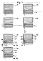
本発明は、流体を供給するカートリッジを提供する。いくつかの実施形態では、カートリッジは、ポンプ室から来るポンプ室導管を位置決めするように円状に移動できる回転弁を備える。回転弁の回転により、ポンプ室導管は様々な他の導管の1つに接続できる。ポンプ室は、回転弁内の空洞と、ポンプ室の容積を変更するように動作可能であるプランジャとにより形成される。いくつかの他の実施形態では、ポンプ室導管を位置決めするためにリニア弁が使用される。 The present invention provides a cartridge for supplying fluid. In some embodiments, the cartridge comprises a rotary valve that can be moved circularly to position a pump chamber conduit coming from the pump chamber. The rotation of the rotary valve allows the pump chamber conduit to be connected to one of various other conduits. The pump chamber is formed by a cavity in the rotary valve and a plunger that is operable to change the volume of the pump chamber. In some other embodiments, a linear valve is used to position the pump chamber conduit.
カートリッジは、流体を収容する貯留槽および流体供給用の出口導管を備える。貯留槽導管は、貯留槽を弁と接続する。いくつかの実施形態では、出口案内導管は、出口ノズルを弁に接続する。弁が異なる位置に移動されるとき、ポンプ室導管は、貯留槽導管または出口導管で位置決めできる。いくつかの実施形態では、弁およびプランジャは、互いに独立して動作または作動させることができ得る。本カートリッジの各実施形態は、カートリッジが少しも流体を喪失させないように、または呼び水による流体喪失が減少させられ得るようにこの各実施形態が動作することができるという利点を有し得る。 The cartridge includes a reservoir for containing fluid and an outlet conduit for fluid supply. A reservoir conduit connects the reservoir to the valve. In some embodiments, the outlet guide conduit connects the outlet nozzle to the valve. When the valve is moved to a different position, the pump chamber conduit can be positioned at the reservoir conduit or outlet conduit. In some embodiments, the valve and plunger can be operated or actuated independently of each other. Each embodiment of the present cartridge may have the advantage that each embodiment can operate so that the cartridge does not lose any fluid or fluid loss due to priming can be reduced.
本明細書に用いられる場合のコントローラは、1つまたは複数の他の装置の動作および/または機能を制御する装置、機械、または機器を包含する。コントローラの例には、コンピュータ、プロセッサ、埋め込みシステムまたはコントローラ、プログラマブル論理コントローラ、およびマイクロコントローラが含まれ得るが、これらに限定されない。本明細書に用いられる場合の「計算装置」または「コンピュータ」は、プロセッサを備えた任意の装置を包含する。本明細書に用いられる場合の「プロセッサ」は、プログラムまたは機械実行可能指令を実行できる電子部品を包含する。 A controller as used herein includes a device, machine, or device that controls the operation and / or function of one or more other devices. Examples of controllers can include, but are not limited to, computers, processors, embedded systems or controllers, programmable logic controllers, and microcontrollers. As used herein, “computing device” or “computer” encompasses any device with a processor. A “processor” as used herein encompasses electronic components that are capable of executing programs or machine-executable instructions.
本明細書に用いられる場合の「コンピュータ可読記憶媒体」は、計算装置のプロセッサにより実行可能である指令を記憶できる任意の有形の記憶媒体を包含する。このコンピュータ可読記憶媒体は、コンピュータ可読持続性記憶媒体と呼ばれ得る。 A “computer-readable storage medium” as used herein includes any tangible storage medium that can store instructions that are executable by the processor of the computing device. This computer readable storage medium may be referred to as a computer readable persistent storage medium.
「コンピュータメモリ」または「メモリ」は、コンピュータ可読記憶媒体の一例である。コンピュータメモリは、プロセッサまたは他のコントローラに直接アクセス可能である任意のメモリである。「コンピュータ記憶部」または「記憶部」は、コンピュータ可読記憶媒体の一例である。コンピュータ記憶部は、任意の不揮発性コンピュータ可読記憶媒体である。 “Computer memory” or “memory” is an example of a computer-readable storage medium. Computer memory is any memory that is directly accessible to a processor or other controller. The “computer storage unit” or “storage unit” is an example of a computer-readable storage medium. The computer storage unit is an arbitrary nonvolatile computer-readable storage medium.
本明細書に用いられる場合の「ユーザインターフェース」は、ユーザまたは操作者がコンピュータまたはコンピュータシステムとやりとりすることを可能にするインターフェースである。 A “user interface” as used herein is an interface that allows a user or operator to interact with a computer or computer system.
本明細書に用いられる場合の「ハードウェアインターフェース」は、プロセッサまたは他のコントローラが外部の計算装置および/または装置とやりとりするおよび/またはそれを制御することを可能にするインターフェースを包含する。ハードウェアインターフェースは、プロセッサが制御信号または指令を外部の計算装置および/または機器へ送信することを可能にすることができる。上記ハードウェアインターフェースは、上記プロセッサまたは他のコントローラがセンサデータを受け取り上記流体の供給を制御することを可能にすることができる。上記ハードウェアインターフェースは、いくつかの実施形態において閉制御ループを形成するために使用され得る。 A “hardware interface” as used herein includes an interface that allows a processor or other controller to interact with and / or control external computing devices and / or devices. The hardware interface may allow the processor to send control signals or instructions to external computing devices and / or equipment. The hardware interface may allow the processor or other controller to receive sensor data and control the fluid supply. The hardware interface may be used to form a closed control loop in some embodiments.
一態様では、本発明は、流体を供給するカートリッジを提供する。カートリッジは、弁を備える。この弁は、流体をポンプ送りするポンプ室を備える。弁は、ポンプ室導管を位置決めするように動作可能である。ポンプ室導管は、ポンプ室と接続されている。弁は、ポンプ室の容積を変更するように動作可能なプランジャをさらに備える。この弁は、貯留槽を弁と接続する貯留槽導管(124、1214)をさらに備え、この弁が、貯留槽導管と接続するようにポンプ室導管を位置決めするように動作可能である。上記弁は、流体を供給する出口導管をさらに備える。回転弁は、出口導管と接続するようにポンプ室導管を回転させるようにさらに動作可能である。 In one aspect, the present invention provides a cartridge for supplying fluid. The cartridge includes a valve. The valve includes a pump chamber that pumps fluid. The valve is operable to position the pump chamber conduit. The pump chamber conduit is connected to the pump chamber. The valve further comprises a plunger operable to change the volume of the pump chamber. The valve further comprises a reservoir conduit (124, 1214) connecting the reservoir with the valve, the valve being operable to position the pump chamber conduit to connect with the reservoir conduit. The valve further comprises an outlet conduit for supplying fluid. The rotary valve is further operable to rotate the pump chamber conduit to connect with the outlet conduit.
別の態様によれば、本発明は、流体を供給するカートリッジを提供する。このカートリッジは、回転弁を備える。この回転弁は、流体をポンプ送りするポンプ室を備える。回転弁は、ポンプ室導管を回転させるように動作可能である。ポンプ室導管は、ポンプ室と接続されている。言い換えると、ポンプ室に接続されるポンプ室導管をその中で有する回転弁が存在する。回転弁を回転させることにより、ポンプ室導管は様々な位置に回転することができ、それによりポンプ室が他の導管に接続されることを可能にする。 According to another aspect, the present invention provides a cartridge for supplying fluid. This cartridge includes a rotary valve. The rotary valve includes a pump chamber that pumps fluid. The rotary valve is operable to rotate the pump chamber conduit. The pump chamber conduit is connected to the pump chamber. In other words, there is a rotary valve having therein a pump chamber conduit connected to the pump chamber. By rotating the rotary valve, the pump chamber conduit can be rotated to various positions, thereby allowing the pump chamber to be connected to other conduits.
カートリッジは、ポンプ室の容積を変更するように動作可能なプランジャをさらに備える。回転弁およびプランジャは、独立して作動させられるように動作可能である。言い換えると、プランジャおよび回転弁は、プランジャが回転弁の位置に影響を与えることなく(その逆も同様)ポンプ室の容積を変更するために使用できるように動作できる。これにより、上記ポンプ室によってより大きいセットのポンプ作用を可能することができる。 The cartridge further comprises a plunger operable to change the volume of the pump chamber. The rotary valve and plunger are operable to be actuated independently. In other words, the plunger and the rotary valve are operable so that the plunger can be used to change the volume of the pump chamber without affecting the position of the rotary valve (and vice versa). Thereby, a larger set of pumping actions can be enabled by the pump chamber.
上記カートリッジは、流体を収容する貯留槽をさらに備える。貯留槽は、様々なやり方で構成することができる。いくつかの実施形態では、貯留槽は、好ましくは射出成形または熱成形プロセスを用いたプラスチック製である、硬い壁に囲まれた室とすることができる。いくつかの実施形態では、貯留槽は、可撓性の壁を備える室であってもよい。いくつかの実施形態では、貯留槽は、小袋または内袋であり得る。他の各実施形態では、貯留槽は、外側容器により支持された小袋または内袋であり得る。他の各実施形態では、貯留槽は管であり得る。 The cartridge further includes a storage tank that contains a fluid. The reservoir can be configured in various ways. In some embodiments, the reservoir may be a hard walled chamber, preferably made of plastic using an injection molding or thermoforming process. In some embodiments, the reservoir may be a chamber with a flexible wall. In some embodiments, the reservoir can be a sachet or an inner bag. In other embodiments, the reservoir may be a sachet or inner bag supported by an outer container. In other embodiments, the reservoir can be a tube.
上記カートリッジは、貯留槽を回転弁と接続する貯留槽導管をさらに備える。回転弁は、貯留槽導管と接続するようにポンプ室導管を回転させるように動作可能である。ポンプ室導管が正しい位置に回転させられるとき、ポンプ室と貯留槽の間に連通が存在する。 The cartridge further includes a reservoir conduit that connects the reservoir to the rotary valve. The rotary valve is operable to rotate the pump chamber conduit to connect with the reservoir conduit. When the pump chamber conduit is rotated to the correct position, there is communication between the pump chamber and the reservoir.
上記カートリッジは、流体を供給すると共に回転弁に接続する出口導管をさらに備える。回転弁は、出口導管に接続するようにポンプ室導管を回転させるようにさらに動作可能である。本実施形態は、回転弁の回転位置の制御およびプランジャの適切な動作によりポンプ室を用いて多様なポンプ作用が行われ得るという利点を有し得る。例えば、回転弁は、ポンプ室導管が貯留槽導管に接続されるように位置決め可能である。この場合には、プランジャは、貯留槽からポンプ室の中に流体を引き込むために使用することもでき、またはポンプ室から貯留槽の中に流体を戻すようにポンプ送りするために使用することもできる。 The cartridge further comprises an outlet conduit for supplying fluid and connecting to a rotary valve. The rotary valve is further operable to rotate the pump chamber conduit to connect to the outlet conduit. This embodiment may have an advantage that various pumping operations can be performed using the pump chamber by controlling the rotational position of the rotary valve and appropriately operating the plunger. For example, the rotary valve can be positioned such that the pump chamber conduit is connected to the reservoir conduit. In this case, the plunger can be used to draw fluid from the reservoir into the pump chamber, or it can be used to pump the fluid back from the pump chamber into the reservoir. it can.
本実施形態は、ポンプ室を用いる他の種類の作用を可能にすることができる。例えば、ポンプ室導管が貯留槽導管と整合または接続されるとき、プランジャは、ポンプ室の容積を増減させるために繰り返し使用することができる。これにより、貯留槽内の流体が混合されることが可能になり得る。また、流体を貯留槽に戻す機能は、浪費される流体の量を減少させることができる。 This embodiment can allow other types of action using the pump chamber. For example, when the pump chamber conduit is aligned or connected to the reservoir conduit, the plunger can be used repeatedly to increase or decrease the volume of the pump chamber. This may allow the fluid in the reservoir to be mixed. The function of returning the fluid to the reservoir can also reduce the amount of wasted fluid.
本実施形態は、ポンプ室のいわゆる浪費が低減された呼び水機能または浪費のない呼び水機能を可能にし、それにより、流体が出口導管を通じて外にポンプ送りされるときに、あり得るほんのごく少量の流体が浪費または廃棄されるかそれが全くないものとすることもできる。例えば、ポンプ室導管が出口導管と接続されるとき、プランジャは、ポンプ室の容積を減少させ、それにより出口導管を通じて流体を外に押し出すまたは供給するために使用することができる。これを行うプロセス中、出口導管から出て行かない出口導管内の流体が存在し得る。正しい量の流体が供給された後、次いで、プランジャが使用されてポンプ室の容積を増大させ、それにより出口導管内に残り得る流体をポンプ室に戻すように引き込むことができる。次いで、流体はポンプ室内で保持することができ、または回転弁が貯留槽導管と整合するように回転されている場合、先に出口導管内にあった流体は、貯留槽の中にポンプ送りして戻すことができる。 This embodiment allows the so-called wasted or non-wasted priming function of the pump chamber so that only a small amount of fluid is possible when the fluid is pumped out through the outlet conduit Can be wasted or discarded, or none at all. For example, when the pump chamber conduit is connected with the outlet conduit, the plunger can be used to reduce the volume of the pump chamber, thereby pushing or delivering fluid out through the outlet conduit. During the process of doing this, there may be fluid in the outlet conduit that does not exit the outlet conduit. After the correct amount of fluid has been supplied, the plunger can then be used to increase the volume of the pump chamber, thereby drawing back any fluid that may remain in the outlet conduit back to the pump chamber. The fluid can then be held in the pump chamber, or if the rotary valve is rotated to align with the reservoir conduit, the fluid that was previously in the outlet conduit is pumped into the reservoir. Can be returned.
回転弁は、流体が貯留槽から思いがけず漏れるのを防止する手段も提供することができる。例えば、回転弁は、いくつかの実施形態において、それが出口導管にも貯留槽導管にも整合しない位置へ回転することができ得る。これにより、流体および/または気体が出口導管から出て行くのを防ぐ、ならびに/あるいは貯留槽内の流体および/または気体がポンプ室の中に漏れるまたは流出するのを防ぐことができる。 The rotary valve can also provide a means for preventing fluid from unexpectedly leaking from the reservoir. For example, the rotary valve may be able to rotate to a position where it does not align with either the outlet conduit or the reservoir conduit in some embodiments. This prevents fluid and / or gas from exiting the outlet conduit and / or prevents fluid and / or gas in the reservoir from leaking into or out of the pump chamber.
別の実施形態では、上記カートリッジは、出口導管に接続された出口ノズルをさらに備える。本明細書に用いられる場合の出口ノズルは、流体の浪費を最小にするノズル設計を包含し、投薬プロセス中に滴がきれいに滴ることを可能にすることができる。例えば、単純な管において、プランジャがポンプ室の容積を減少させるために使用された後、流体の滴がノズルの外側に垂れ下がる場合がある。出口ノズルの形状または機能は、流体の滴が出口ノズルから垂れ下がる機会を減少させるように設計することができる。例えば、この出口ノズルは、いわゆるカモノハシ形状を有し、カモノハシノズルであり得る。 In another embodiment, the cartridge further comprises an outlet nozzle connected to the outlet conduit. The exit nozzle, as used herein, can include a nozzle design that minimizes fluid waste and can allow drops to drip cleanly during the dosing process. For example, in a simple tube, a drop of fluid may hang outside the nozzle after the plunger is used to reduce the volume of the pump chamber. The shape or function of the outlet nozzle can be designed to reduce the chance that a drop of fluid will hang from the outlet nozzle. For example, the outlet nozzle has a so-called platypus shape and can be a platypus nozzle.
他の各実施形態では、上記カートリッジは、ポンプ室がこれらの追加の貯留槽に接続されることを可能にする追加の貯留槽および追加の貯留槽導管を有することができる。典型的には、カートリッジは、ただ1種類の流体または試薬を収容することができる。いくつかの実施形態では、これは、様々な検査に使用または要求される希釈剤であり得る。回転弁が特定の回転位置にあるときにポンプ室導管にアクセス可能な導管にそれぞれ接続することができる複数の貯留槽も存在できる。 In other embodiments, the cartridge can have additional reservoirs and additional reservoir conduits that allow the pump chamber to be connected to these additional reservoirs. Typically, the cartridge can contain only one type of fluid or reagent. In some embodiments, this may be a diluent used or required for various tests. There can also be a plurality of reservoirs that can each be connected to a conduit accessible to the pump chamber conduit when the rotary valve is in a particular rotational position.
例えば、多くの臨床検査の場合、2つの貯留槽が存在し得、免疫測定法の場合、異なる貯留槽内に2つまたは3つの異なる流体が存在し得る。本実施形態のいくつかの変形例では、カートリッジは、複数のポンプユニットを有することができ、各ポンプユニットは、その回転弁を介して1つまたは複数の貯留槽に接続されている。このようにして、免疫測定法は別個のポンプユニットを用いて供給され、それらはポンプ送り工程により混合されない。 For example, for many clinical tests, there may be two reservoirs, and for immunoassays there may be two or three different fluids in different reservoirs. In some variations of this embodiment, the cartridge can have a plurality of pump units, each pump unit being connected to one or more reservoirs via its rotary valve. In this way, immunoassays are supplied using separate pump units, which are not mixed by the pumping process.
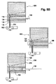
別の実施形態では、上記カートリッジは、貯留槽に接続された戻し導管をさらに備える。ポンプ室導管は、貯留槽の第1の部分から流体を受け入れるように動作可能である。戻し導管は、貯留槽の第2の部分へ流体を戻すように動作可能である。回転弁は、戻し導管に接続するようにポンプ室導管を回転させるようにさらに動作可能である。本実施形態は、例えば、流体が貯留槽に戻されるときに気体の気泡を潜在的に生じさせる影響を減少させることができるので、有益であり得る。本実施形態は、気泡を貯留槽の第2の部分へ通過させることにより貯留槽の第1の部分内の気泡の個数を減少させるという利益をさらに有し得る。 In another embodiment, the cartridge further comprises a return conduit connected to the reservoir. The pump chamber conduit is operable to receive fluid from the first portion of the reservoir. The return conduit is operable to return fluid to the second portion of the reservoir. The rotary valve is further operable to rotate the pump chamber conduit to connect to the return conduit. This embodiment may be beneficial, for example, because it can reduce the effects of potentially creating gas bubbles when fluid is returned to the reservoir. This embodiment may further have the benefit of reducing the number of bubbles in the first portion of the reservoir by passing the bubbles through the second portion of the reservoir.
例えば、ポンプ室導管が貯留槽導管と整合にあるように回転弁が回転されるときに、流体は、貯留槽から引き出すことができる。ある量の流体が出口導管を通じて供給された後、回転弁は、ポンプ室導管が戻し導管と整合にあるような位置に回転することができる。貯留槽導管は貯留槽の一の部分から流体を引き出すことができ、戻し導管は、貯留槽の異なる部分へこの流体を戻すために使用される。例えば、貯留槽導管および戻し導管の2つの位置は、流体が貯留槽からポンプ室の中に引き出されるときに、戻し導管を通じて貯留槽に入る気泡が貯留槽導管の中に引き込まれることがまずないように十分遠く離され得る。 For example, fluid can be withdrawn from the reservoir when the rotary valve is rotated so that the pump chamber conduit is aligned with the reservoir conduit. After an amount of fluid has been supplied through the outlet conduit, the rotary valve can rotate to a position such that the pump chamber conduit is aligned with the return conduit. The reservoir conduit can draw fluid from one part of the reservoir and the return conduit is used to return this fluid to a different part of the reservoir. For example, the two locations of the reservoir conduit and the return conduit are such that when fluid is drawn from the reservoir into the pump chamber, bubbles that enter the reservoir through the return conduit are unlikely to be drawn into the reservoir conduit. Can be so far away.
別の実施形態では、カートリッジは、副貯留槽をさらに備える。カートリッジは、副貯留槽導管をさらに備える。回転弁は、副貯留槽導管に接続するようにポンプ室導管を回転させるようにさらに動作可能である。本実施形態は、それが第2のまたは異なる流体がカートリッジを用いて収容および供給されることを可能にすることができそれは廃液が副貯留槽に配置されることも可能にすることができるので有利であり得る。 In another embodiment, the cartridge further comprises a secondary reservoir. The cartridge further comprises a secondary reservoir conduit. The rotary valve is further operable to rotate the pump chamber conduit to connect to the secondary reservoir conduit. This embodiment can allow a second or different fluid to be accommodated and supplied using the cartridge, since it can also allow waste liquid to be placed in the secondary reservoir. Can be advantageous.
追加の貯留槽が第3の貯留槽および第3の貯留槽導管、第4の貯留槽および第4の貯留槽導管などを加えることによりカートリッジに加えることができ、それにより任意の個数の貯留槽および貯留槽導管がカートリッジに加えられてもよいことに留意されたい。 Additional reservoirs can be added to the cartridge by adding a third reservoir and a third reservoir conduit, a fourth reservoir and a fourth reservoir conduit, etc., thereby allowing any number of reservoirs Note that a reservoir conduit may also be added to the cartridge.
別の実施形態では、カートリッジが接続導管をさらに備える。接続導管は、副貯留槽と貯留槽の間で流体を移送するように動作可能である。本実施形態は、接続導管が副貯留槽を貯留槽へ流体を戻すために流体を預ける場所として使用することを可能にすることができるので有益であり得る。 In another embodiment, the cartridge further comprises a connecting conduit. The connecting conduit is operable to transfer fluid between the secondary reservoir and the reservoir. This embodiment may be beneficial because the connecting conduit can allow the secondary reservoir to be used as a deposit location for returning fluid to the reservoir.
別の実施形態では、カートリッジは、接続導管を塞ぐ膜を備える。この膜は、流体を通すことができる。本実施形態は、流体が副貯留槽から貯留槽の中に戻っているときに流体をフィルタにかけるまたは気体の気泡を阻止する手段を提供することができるので有益であり得る。 In another embodiment, the cartridge comprises a membrane that plugs the connecting conduit. This membrane can pass fluids. This embodiment may be beneficial because it can provide a means to filter the fluid or prevent gas bubbles when the fluid is returning from the secondary reservoir into the reservoir.
別の実施形態では、副貯留槽は気泡案内構造を備える。本明細書に用いられる場合の気泡案内構造は、貯留槽内の所定の位置へまたは通気穴に向けて気体の気泡を案内するために使用される構造を包含する。いくつかの実施では、気泡案内構造は、流体が貯留槽を通じて移動しているときに流体が気泡を回すことを可能にし得る。例えば、気泡構造は、気泡を配置および案内するために使用される1セットの畝であり得る。構造および畝は共に十分に近く間隔をおいて配置することができ、それにより流体が気泡を一回りさせることを可能にする領域の中に気泡が入るのを流体の表面張力が防ぐようになっている。気泡が適切に閉じ込められない場合、気泡は副貯留槽内の特定の位置で動かなくなる可能性があり副貯留槽の上部へ行くことができず、または接続導管が存在する場合には流体は貯留槽に戻ることができるので、これは有益であり得る。 In another embodiment, the secondary reservoir comprises a bubble guide structure. Bubble guide structures as used herein include structures used to guide gas bubbles to a predetermined location in a reservoir or toward a vent. In some implementations, the bubble guide structure may allow the fluid to turn the bubble as the fluid is moving through the reservoir. For example, the bubble structure may be a set of ridges used to place and guide the bubbles. Both the structure and the heel can be spaced sufficiently close together so that the surface tension of the fluid prevents the bubbles from entering the region that allows the fluid to circulate the bubbles. ing. If air bubbles are not properly confined, the air bubbles may become stuck at certain locations within the secondary reservoir and cannot reach the top of the secondary reservoir, or fluid will be stored if a connecting conduit is present. This can be beneficial as it can be returned to the tank.
別の実施形態では、貯留槽および/または副貯留槽は、通気穴を備える。本明細書に用いられる場合の通気穴は、空気泡または他の気体容積がカートリッジに出入りすることを可能にする構造である。代替として、貯留槽はそのような通気穴を備え、または貯留槽と第2の貯留槽の両方が、そのような通気穴を備える。 In another embodiment, the reservoir and / or sub-reservoir comprises a vent hole. A vent hole as used herein is a structure that allows air bubbles or other gas volumes to enter and exit the cartridge. Alternatively, the reservoir is provided with such vent holes, or both the reservoir and the second reservoir are provided with such vent holes.
別の実施形態では、通気穴は、フィルタで覆われまたは封止されている。フィルタは、カートリッジ内に流体を封止するように動作可能である。フィルタは、いくつかの実施形態では、疎水性とすることができる。いくつかの実施形態では、気体フィルタは、気体だけを通過させると共に液体を通過させないために微細孔を有することができる。いくつかの実施形態では、フィルタは、ポリテトラフルオロエチレン、炭素繊維、PTFEで被覆された炭素繊維、カーボンナノチューブ、高分子繊維、またはフッ素重合体繊維の多孔質形態とすることができるが、これに限定されない。 In another embodiment, the vent is covered or sealed with a filter. The filter is operable to seal fluid within the cartridge. The filter may be hydrophobic in some embodiments. In some embodiments, the gas filter can have micropores to pass only gas and not liquid. In some embodiments, the filter can be a porous form of polytetrafluoroethylene, carbon fiber, carbon fiber coated with PTFE, carbon nanotube, polymer fiber, or fluoropolymer fiber, It is not limited to.
別の実施形態では、流体は磁性粒子を含む。
別の実施形態では、流体はラテックス粒子を含む。
別の実施形態では、流体は血液型判定試薬を含む。
In another embodiment, the fluid includes magnetic particles.
In another embodiment, the fluid comprises latex particles.
In another embodiment, the fluid includes a blood grouping reagent.
別の実施形態では、流体は免疫試薬を含む。
別の実施形態では、流体は抗体を含む。
別の実施形態では、流体は酵素を含む。
In another embodiment, the fluid contains an immunoreagent.
In another embodiment, the fluid comprises an antibody.
In another embodiment, the fluid includes an enzyme.
別の実施形態では、流体は組換えタンパク質を含む。
別の実施形態では、流体はウイルス分離株を含む。
別の実施形態では、流体はウイルスを含む。
In another embodiment, the fluid comprises a recombinant protein.
In another embodiment, the fluid comprises a virus isolate.
In another embodiment, the fluid comprises a virus.
別の実施形態では、流体は生物学的試薬を含む。
別の実施形態では、流体は溶剤を含む。
別の実施形態では、流体は希釈剤を含む。
In another embodiment, the fluid includes a biological reagent.
In another embodiment, the fluid includes a solvent.
In another embodiment, the fluid includes a diluent.
別の実施形態では、流体は分散体を含む。
別の実施形態では、流体はナノ粒子を含む。
別の実施形態では、流体はタンパク質を含む。
In another embodiment, the fluid comprises a dispersion.
In another embodiment, the fluid comprises nanoparticles.
In another embodiment, the fluid comprises a protein.
別の実施形態では、流体は塩を含む。
別の実施形態では、流体は洗剤を含む。
別の実施形態では、流体は核酸を含む。
In another embodiment, the fluid includes a salt.
In another embodiment, the fluid includes a detergent.
In another embodiment, the fluid comprises a nucleic acid.
別の実施形態では、流体は酸を含む。
別の実施形態では、流体は塩基を含む。
別の実施形態では、流体は、粒子懸濁液、液体試薬、液体接着剤、液体食品生産物、液体金属(例えば、はんだ)、および/または任意の他の液体を含み得る。
In another embodiment, the fluid comprises an acid.
In another embodiment, the fluid includes a base.
In another embodiment, the fluid may include a particle suspension, liquid reagent, liquid adhesive, liquid food product, liquid metal (eg, solder), and / or any other liquid.
別の実施形態では、カートリッジは、出口導管により供給される流体を計測するように動作可能なセンサをさらに備える。例えば、このセンサは、容量センサまたは光センサとすることができる。 In another embodiment, the cartridge further comprises a sensor operable to measure fluid supplied by the outlet conduit. For example, the sensor can be a capacitive sensor or an optical sensor.
別の実施形態では、カートリッジが、回転弁およびプランジャをアクチュエータ組立体に取り付ける結合組立体をさらに備える。本実施形態は、本実施形態が回転弁およびプランジャがアクチュエータにうまい具合に接続されることを可能にできるので、有益であり得る。いくつかの実施形態における結合組立体は、回転弁およびプランジャがアクチュエータ組立体により独立して作動させられることを可能にすることができる。 In another embodiment, the cartridge further comprises a coupling assembly that attaches the rotary valve and plunger to the actuator assembly. This embodiment may be beneficial because this embodiment can allow the rotary valve and plunger to be successfully connected to the actuator. The coupling assembly in some embodiments can allow the rotary valve and plunger to be actuated independently by the actuator assembly.
いくつかの実施形態では、それ自体のアクチュエータを備えたカートリッジを有することも可能であり得る。この場合には、カートリッジは、アクチュエータをさらに備える。場合によっては、アクチュエータは結合組立体に接続されてよく、またはアクチュエータは、回転弁とプランジャを独立して直接作動させるように設計または動作可能であってもよい。 In some embodiments, it may be possible to have a cartridge with its own actuator. In this case, the cartridge further includes an actuator. In some cases, the actuator may be connected to the coupling assembly, or the actuator may be designed or operable to actuate the rotary valve and plunger directly and independently.
ここで使用される場合のポンプユニットは、流体をポンプ送りするための回転弁およびプランジャを包含する。自動分析器の中に装着されるとき、ポンプユニットごとに1つのアクチュエータが存在でき、または、自動分析器内のカートリッジの全部を作動させるために動かされ使用される1つのアクチュエータが存在できる。この場合には、カートリッジと単一のアクチュエータの間の相対位置を移動させる機構が存在できる。一群のカートリッジ用のアクチュエータが存在することもできる。 The pump unit as used herein includes a rotary valve and a plunger for pumping fluid. When mounted in an autoanalyzer, there can be one actuator per pump unit, or there can be one actuator that is moved and used to actuate all of the cartridges in the autoanalyzer. In this case, there can be a mechanism for moving the relative position between the cartridge and the single actuator. There may also be an actuator for a group of cartridges.
例えば、カートリッジの異なる構成が存在し得る。いくつかの実施形態では、カートリッジは、単一のポンプユニットを有することができる。この単一のポンプユニットは、異なる貯留槽に接続された導管を有することができる。これにより、カートリッジが同一のカートリッジから異なる種類の流体をポンプ送りすることを可能にすることができる。別の例では、カートリッジは、複数のポンプユニットを有することができ、各ポンプユニットは、その回転弁を介して1つまたは複数の貯留槽に接続されている。 For example, different configurations of the cartridge can exist. In some embodiments, the cartridge can have a single pump unit. This single pump unit can have conduits connected to different reservoirs. This can allow the cartridges to pump different types of fluid from the same cartridge. In another example, the cartridge can have a plurality of pump units, each pump unit being connected to one or more reservoirs via its rotary valve.
いくつかの実施形態では、カートリッジは、ポンプユニットおよび取付可能な貯留槽を備える。本実施形態は、一般的なポンプユニットが作製され得ると共に必要に応じて貯留槽が取り付けられるので有益であり得る。これにより、より多様な流体を利用可能にさせることができる。異なる容積の貯留槽が選択されてもよい。異なるポンプユニットが、選択されることも可能である。そのような異なるポンプユニットは、例えば、異なるストロークおよび/または直径を有するプランジャを有することができる。これは、ポンプユニットの容積に影響を及ぼし得る。いくつかの応用例では、より大きい容積をより正確にポンプ送りすることが望ましいものであり得、他の応用例では、より小さいがより正確なポンプ容積が望まれ得る。したがって、ポンプユニットおよび取付可能な貯留槽の使用により、異なる種類および/または容積の流体を備えた貯留槽と定められた容積のこの流体を供給するように最適化されているポンプユニットとを組み合わせることを可能にするモジュールの概念を実現することを可能にする。このモジュールの概念は、異なるやり方で組み合わせることができる小さいセットのポンプユニットおよび/または貯留槽に基づいて大きいセットの最適化されたカートリッジを提供することを可能にする。ポンプユニットおよび取付可能な貯留槽の組立体は、カートリッジ製造中に製造ステップとして工場敷地で行うことができ、または例えば、カートリッジを自動分析器に挿入する前にポンプユニットと取付可能な貯留槽を組み立てることによりユーザ敷地で行うことができる。 In some embodiments, the cartridge comprises a pump unit and an attachable reservoir. This embodiment may be beneficial because a general pump unit can be made and a reservoir is attached as needed. Thereby, more various fluids can be made available. Different volume reservoirs may be selected. Different pump units can also be selected. Such different pump units can have, for example, plungers with different strokes and / or diameters. This can affect the volume of the pump unit. In some applications it may be desirable to pump a larger volume more accurately, and in other applications a smaller but more accurate pump volume may be desired. Thus, the use of a pump unit and attachable reservoir combines a reservoir with a different type and / or volume of fluid with a pump unit that is optimized to supply a defined volume of this fluid Makes it possible to realize the concept of modules that make it possible. This modular concept makes it possible to provide a large set of optimized cartridges based on a small set of pump units and / or reservoirs that can be combined in different ways. The assembly of the pump unit and attachable reservoir can be done on the factory site as a manufacturing step during cartridge manufacture, or for example, the reservoir that can be attached to the pump unit before inserting the cartridge into the automated analyzer. It can be done at the user site by assembling.
別の実施形態では、回転弁が円筒形部分を備える。ポンプ室が回転弁内の空洞である。ポンプ室が空洞およびプランジャにより形成される。カートリッジは、円筒形部分を受け入れる円筒形空間を有するカートリッジ本体を備える。回転弁が、円筒形空間内で回転するように動作可能である。 In another embodiment, the rotary valve comprises a cylindrical portion. The pump chamber is a cavity in the rotary valve. A pump chamber is formed by the cavity and the plunger. The cartridge includes a cartridge body having a cylindrical space that receives a cylindrical portion. A rotary valve is operable to rotate within the cylindrical space.
別の実施形態では、貯留槽導管および出口導管は、円筒形空間に位置する。ポンプ室導管は、円筒形部分に位置する。
別の実施形態では、カートリッジは複数のポンプユニットを備える。
In another embodiment, the reservoir conduit and the outlet conduit are located in a cylindrical space. The pump chamber conduit is located in the cylindrical portion.
In another embodiment, the cartridge comprises a plurality of pump units.
別の実施形態では、カートリッジは複数の貯留槽を備える。
別の実施形態では、複数の貯留槽は、異なる流体で充填される。
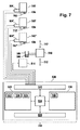
別の態様によれば、本発明は、生体試料を分析する自動分析器を提供する。自動システムは、本発明の一実施形態によるカートリッジを保持するように動作可能である。自動分析器は、プランジャおよび弁を作動させるように動作可能なアクチュエータ組立体を備える。自動分析器は、アクチュエータ組立体の動作を制御するコントローラ(520、1920)をさらに備える。
In another embodiment, the cartridge comprises a plurality of reservoirs.
In another embodiment, the plurality of reservoirs are filled with different fluids.
According to another aspect, the present invention provides an automated analyzer for analyzing a biological sample. The automated system is operable to hold a cartridge according to one embodiment of the present invention. The automated analyzer includes an actuator assembly operable to actuate the plunger and valve. The automatic analyzer further comprises a controller (520, 1920) that controls the operation of the actuator assembly.
別の態様によれば、本発明は、本発明の一実施形態によるカートリッジを保持する自動分析器を提供する。本明細書に用いられる場合の自動分析器は、生体試料を自動的に分析するシステムを包含する。自動分析器が、プランジャを直線作動させると共に回転弁を回転作動させるように動作可能であるアクチュエータ組立体を備える。アクチュエータ組立体が、プランジャおよび回転弁を独立して作動させるようにさらに動作可能である。自動分析器が、アクチュエータ組立体の動作を制御するコントローラをさらに備える。 According to another aspect, the present invention provides an automated analyzer for holding a cartridge according to one embodiment of the present invention. As used herein, an automated analyzer includes a system that automatically analyzes a biological sample. The automated analyzer includes an actuator assembly operable to linearly actuate the plunger and to actuate the rotary valve. The actuator assembly is further operable to actuate the plunger and the rotary valve independently. The automatic analyzer further comprises a controller that controls the operation of the actuator assembly.
いくつかの実施形態では、上記自動分析器は、本発明の一実施形態による複数のカートリッジを保持するようになされ得る。この場合には、カートリッジと反応管/キュベットの間の相対移動を実現する機構が存在し得る。ポンプユニットごとに1つのアクチュエータが存在でき、または複数のカートリッジに用いられる1つのアクチュエータが存在できる。この場合には、カートリッジとアクチュエータの間の相対移動を実現する機構またはロボットシステムが存在できる。一群のカートリッジにそれぞれ用いられる複数のアクチュエータが存在する実施形態も存在し得る。一群のカートリッジは予め決定することができ、または一群のカートリッジは臨機応変に決定されてもよい。代替として、複数のアクチュエータは、例えば、事前供給または事後供給行為のような異なる目的のために、カートリッジまたは一群のカートリッジに用いられてもよい。 In some embodiments, the automated analyzer can be adapted to hold a plurality of cartridges according to an embodiment of the invention. In this case, there may be a mechanism to achieve relative movement between the cartridge and the reaction tube / cuvette. There can be one actuator per pump unit, or there can be one actuator used for multiple cartridges. In this case, there can be a mechanism or a robot system that realizes the relative movement between the cartridge and the actuator. There may also be embodiments where there are multiple actuators each used for a group of cartridges. The group of cartridges can be predetermined, or the group of cartridges can be determined on an ad hoc basis. Alternatively, multiple actuators may be used on a cartridge or group of cartridges for different purposes, such as pre-feed or post-feed actions.
別の実施形態では、自動分析器は、カートリッジを備える。
別の実施形態では、コントローラは、回転弁を回転させることにより貯留槽導管と接続するようにポンプ室導管を回転させるようにアクチュエータ組立体を制御するように動作可能である。コントローラは、プランジャを用いてポンプ室の容積を増大させることによりポンプ室を充填するようにアクチュエータ組立体を制御するようにさらに動作可能である。コントローラは、回転弁を回転させることにより出口導管と接続するようにポンプ室導管を回転させるようにアクチュエータ組立体を制御するようにさらに動作可能である。コントローラは、プランジャを用いてポンプ室の容積を減少させることにより出口導管を通じて流体をポンプ送りするようにアクチュエータ組立体を制御するようにさらに動作可能である。本実施形態は、出口導管を通じて流体をポンプ送りする方法を提供するので有益であり得る。
In another embodiment, the automated analyzer comprises a cartridge.
In another embodiment, the controller is operable to control the actuator assembly to rotate the pump chamber conduit to connect with the reservoir conduit by rotating the rotary valve. The controller is further operable to control the actuator assembly to fill the pump chamber by using a plunger to increase the volume of the pump chamber. The controller is further operable to control the actuator assembly to rotate the pump chamber conduit to connect with the outlet conduit by rotating the rotary valve. The controller is further operable to control the actuator assembly to pump fluid through the outlet conduit by reducing the volume of the pump chamber using a plunger. This embodiment may be beneficial because it provides a method of pumping fluid through an outlet conduit.
別の実施形態では、コントローラは、プランジャを用いてポンプ室の容積を増大させることにより出口導管から流体を受け入れるようにアクチュエータ組立体を制御するように動作可能である。 In another embodiment, the controller is operable to control the actuator assembly to receive fluid from the outlet conduit by using a plunger to increase the volume of the pump chamber.
別の実施形態では、コントローラは、回転弁を回転させることにより貯留槽導管と接続するようにポンプ室導管を回転させるようにアクチュエータ組立体を制御するように動作可能である。コントローラは、プランジャを用いてポンプ室の容積を減少させることにより貯留槽へ流体を戻すようにアクチュエータ組立体を制御するようにさらに動作可能である。本実施形態は、呼び水なしでポンプの動作を実現するので、有利であり得る。流体の100%またはほぼ100%が使用できる。 In another embodiment, the controller is operable to control the actuator assembly to rotate the pump chamber conduit to connect with the reservoir conduit by rotating the rotary valve. The controller is further operable to control the actuator assembly to return fluid to the reservoir by reducing the volume of the pump chamber using a plunger. This embodiment may be advantageous because it achieves pump operation without priming. 100% or nearly 100% of the fluid can be used.
別の実施形態では、コントローラは、回転弁を回転させることにより貯留槽導管と接続するようにポンプ室導管を回転させるようにアクチュエータ組立体を制御するように動作可能である。コントローラは、プランジャを用いてポンプ室の容積を繰り返し増減させることにより貯留槽内で流体を混合するようにアクチュエータ組立体を制御するようにさらに動作可能である。流体が磁性粒子またはラテックス粒子などのビーズまたは粒子を含む場合、本実施形態は、流体とその合成物を混合するために使用することができる。 In another embodiment, the controller is operable to control the actuator assembly to rotate the pump chamber conduit to connect with the reservoir conduit by rotating the rotary valve. The controller is further operable to control the actuator assembly to mix fluid within the reservoir by repeatedly increasing and decreasing the volume of the pump chamber using a plunger. If the fluid comprises beads or particles such as magnetic particles or latex particles, this embodiment can be used to mix the fluid and its composition.
別の実施形態では、カートリッジが出口ノズルを備える。自動分析器が、流体のメニスカスを検出するメニスカス検出器をさらに備える。コントローラは、出口ノズルを通じて流体を押し出すようにアクチュエータを制御するように動作可能である。コントローラは、メニスカス検出器を用いてメニスカスを検出するようにさらに動作可能である。コントローラは、メニスカスが所定の位置にあるときに、出口を通じた流体の送り出しを停止するようにアクチュエータを制御するようにさらに動作可能である。本実施形態は、流体のより正確でより精密な供給を可能にし得るので有益であり得る。本実施形態は、メニスカスが流体の供給が始まるときと同じ位置にある場合、流体の供給は、より正確、より精密、および/またはより再現可能になり得るので、有益であり得る。メニスカスは、出口ノズルの内側または外側にあってもよい。例えば、出口ノズルは長い管状構造とすることができ、メニスカスは管内の特定の位置を有することができる。他の各実施形態では、メニスカスは、出口ノズルから垂れ下がる流体の滴により形成され得る。多くの応用例では、好ましくは、メニスカスは、出口ノズルのまさに孔に位置する。 In another embodiment, the cartridge comprises an outlet nozzle. The automatic analyzer further comprises a meniscus detector for detecting the meniscus of the fluid. The controller is operable to control the actuator to push fluid through the outlet nozzle. The controller is further operable to detect the meniscus using a meniscus detector. The controller is further operable to control the actuator to stop delivering fluid through the outlet when the meniscus is in place. This embodiment may be beneficial because it may allow for a more accurate and precise supply of fluid. This embodiment may be beneficial when the meniscus is in the same position as when fluid delivery begins, as fluid delivery may be more accurate, more precise, and / or more reproducible. The meniscus may be inside or outside the outlet nozzle. For example, the exit nozzle can be a long tubular structure and the meniscus can have a specific location within the tube. In other embodiments, the meniscus may be formed by a drop of fluid depending from the exit nozzle. For many applications, preferably the meniscus is located in the very hole of the outlet nozzle.
別の実施形態では、コントローラは、出口を通じて流体の予め定められた容積を押し出すようにアクチュエータを制御するようにさらに動作可能である。いくつかの実施形態では、アクチュエータは、メニスカスが所定の位置にある後に出口ノズルを通じて流体の予め定められた容積を押し出すように制御することができる。 In another embodiment, the controller is further operable to control the actuator to push a predetermined volume of fluid through the outlet. In some embodiments, the actuator can be controlled to push a predetermined volume of fluid through the outlet nozzle after the meniscus is in place.
別の実施形態では、メニスカス検出器は、容量センサ、光センサ、およびカメラのいずれか1つである。メニスカスがノズルの内側にあるとき、容量センサは、メニスカスの位置を検出するために使用することができる。ノズルが光学的に透明である場合には、光センサは、ノズル内のメニスカスの位置を決定するために使用することもできる。メニスカスがノズルを越えて延びている場合、容量センサ、光センサ、またはカメラがそれぞれ使用されて、メニスカスの位置を決定することができる。 In another embodiment, the meniscus detector is any one of a capacitive sensor, a light sensor, and a camera. When the meniscus is inside the nozzle, the capacitive sensor can be used to detect the position of the meniscus. If the nozzle is optically transparent, the light sensor can also be used to determine the position of the meniscus in the nozzle. If the meniscus extends beyond the nozzle, a capacitive sensor, light sensor, or camera can each be used to determine the position of the meniscus.
別の実施形態では、自動分析器は、複数のカートリッジを保持するように動作可能である。各複数のカートリッジは、本発明の一実施形態による。
別の実施形態では、自動分析器は、複数のカートリッジをさらに備える。
In another embodiment, the automated analyzer is operable to hold multiple cartridges. Each of the plurality of cartridges is according to an embodiment of the present invention.
In another embodiment, the automated analyzer further comprises a plurality of cartridges.
複数のカートリッジを有する本実施形態は、様々なやり方で実施することができる。例えば、各ポンプユニットは、それ自体のアクチュエータ組立体を有することができる。これは、並行な動作であり得る。別の例では、カートリッジは、同一のアクチュエータ組立体上へ動かし配置することができ、またはアクチュエータ組立体は、異なるカートリッジの間、もしくは同一のカートリッジの一部である異なるポンプユニットの間でも動かすことができる。さらに他の実施形態では、複数のアクチュエータが存在でき、および複数のカートリッジが、これらの複数のアクチュエータの間で機械式ロボットシステムを介して動かすことができる。 This embodiment with multiple cartridges can be implemented in various ways. For example, each pump unit can have its own actuator assembly. This can be a parallel operation. In another example, the cartridges can be moved and placed on the same actuator assembly, or the actuator assemblies can be moved between different cartridges or even between different pump units that are part of the same cartridge. Can do. In still other embodiments, multiple actuators can be present and multiple cartridges can be moved between these multiple actuators via a mechanical robotic system.
別の実施形態では、自動分析器は、流体の供給を測定または計測するように動作可能なセンサまたは計測システムを備える。コントローラは、このセンサまたは計測システムから受け取った測定値またはデータに従って流体の供給を制御するように動作可能である。言い換えると、コントローラは、センサを用いた閉ループ制御システムまたは流体の供給を制御する計測システムを形成するように動作可能である。 In another embodiment, the automated analyzer comprises a sensor or measurement system operable to measure or measure the supply of fluid. The controller is operable to control the supply of fluid in accordance with measurements or data received from the sensor or measurement system. In other words, the controller is operable to form a closed loop control system using sensors or a measurement system that controls fluid supply.
別の態様によれば、本発明は、本発明の一実施形態によるカートリッジを動作させる方法を提供する。方法は、貯留槽導管と接続するように回転弁を回転させてポンプ室導管を回転させるステップと、ポンプ室を充填するようにプランジャを用いてポンプ室の容積を増大させるステップと、出口導管と接続するように回転弁を回転させてポンプ室導管を回転させるステップと、出口導管を通じて流体をポンプ送りするようにプランジャを用いてポンプ室の容積を減少させるステップとを含む。 According to another aspect, the present invention provides a method of operating a cartridge according to one embodiment of the present invention. The method includes rotating a rotary valve to connect the reservoir conduit to rotate the pump chamber conduit, increasing the volume of the pump chamber with a plunger to fill the pump chamber, and an outlet conduit. Rotating the rotary valve to connect and rotating the pump chamber conduit, and using the plunger to reduce the volume of the pump chamber to pump fluid through the outlet conduit.
別の実施形態では、この方法は、出口導管から流体を取り出すためにプランジャを用いてポンプ室の容積を増大させるステップをさらに含む。
別の実施形態では、この方法は、貯留槽導管と接続するように回転弁を回転させてポンプ室導管を回転させるステップと、プランジャを用いてポンプ室の容積を減少させることにより貯留槽へ流体を戻すステップとをさらに含む。
In another embodiment, the method further includes increasing the volume of the pump chamber with a plunger to remove fluid from the outlet conduit.
In another embodiment, the method includes rotating the rotary valve to connect the reservoir conduit to rotate the pump chamber conduit, and using a plunger to reduce the volume of the pump chamber to fluid to the reservoir. And a step of returning.
別の実施形態では、上記方法は、貯留槽導管と接続するように回転弁を回転させてポンプ室導管を回転させるステップと、貯留槽内で流体を混合するようにプランジャを用いてポンプ室の容積を繰り返し増減させるステップとをさらに含む。 In another embodiment, the method includes rotating a rotary valve to connect the reservoir conduit to rotate the pump chamber conduit, and using a plunger to mix the fluid in the reservoir. And repeatedly increasing and decreasing the volume.
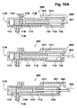
一態様では、本発明は、流体を供給するカートリッジを提供する。カートリッジは滑り弁を備える。この滑り弁は、直線運動をとる。滑り弁は、直線弁とも呼ばれ得る。滑り弁は、流体をポンプ送りするポンプ室を備える。滑り弁は、ポンプ室導管を並進移動させるように動作可能である。ポンプ室導管がポンプ室と接続される。カートリッジは、ポンプ室の容積を変更するように動作可能なプランジャをさらに備える。カートリッジは、流体を収容する貯留槽をさらに備える。カートリッジは、貯留槽を滑り弁と接続する貯留槽導管をさらに備える。滑り弁が貯留槽導管と接続するようにポンプ室導管を並進移動させるように動作可能である。カートリッジは、流体を供給する出口導管をさらに備える。滑り弁が出口導管と接続するようにポンプ室導管を並進移動させるように動作可能である。本実施形態は、滑り弁とプランジャの組み合わせにより流体の正確な供給を可能にするので有益であり得る。さらに、本実施形態は、カートリッジにより流体を供給するときに減じられた量の廃液を生産することも可能にし得る。 In one aspect, the present invention provides a cartridge for supplying fluid. The cartridge includes a slide valve. This slide valve takes a linear motion. A slip valve may also be referred to as a straight valve. The slide valve includes a pump chamber for pumping fluid. The slide valve is operable to translate the pump chamber conduit. A pump chamber conduit is connected to the pump chamber. The cartridge further comprises a plunger operable to change the volume of the pump chamber. The cartridge further includes a storage tank that stores the fluid. The cartridge further comprises a reservoir conduit connecting the reservoir with the slip valve. The pump chamber conduit is operable to translate so that the slip valve connects with the reservoir conduit. The cartridge further comprises an outlet conduit for supplying fluid. The pump chamber conduit is operable to translate so that the slip valve connects with the outlet conduit. This embodiment may be beneficial because it allows a precise supply of fluid by a combination of a slide valve and a plunger. Furthermore, the present embodiment may also allow a reduced amount of waste liquid to be produced when fluid is supplied by the cartridge.
各実施形態は、上記ポンプ室によるより大きいセットのポンプ作用が可能であるという利点を有することにもなり得る。本実施形態は、滑り弁の位置の並進移動およびプランジャの適切な動作を制御することによりポンプ室を用いて多様なポンプ作用が行われ得るという利点を有し得る。例えば、滑り弁は、ポンプ室導管が貯留槽導管に接続されるように位置決め可能である。この場合には、プランジャは、貯留槽からポンプ室の中に流体を引き込むために使用することができ、またはポンプ室から貯留槽の中に流体を戻すようにポンプ送りするために使用することもできる。 Each embodiment may also have the advantage that a larger set of pumping actions by the pump chamber is possible. This embodiment may have the advantage that various pumping actions can be performed using the pump chamber by controlling the translation of the position of the slide valve and the proper operation of the plunger. For example, the slip valve can be positioned such that the pump chamber conduit is connected to the reservoir conduit. In this case, the plunger can be used to draw fluid from the reservoir into the pump chamber, or it can be used to pump the fluid back from the pump chamber into the reservoir. it can.
本実施形態は、ポンプ室を用いる他の種類の作用を可能にすることができる。例えば、ポンプ室導管が貯留槽導管と整合または接続されるとき、プランジャは、ポンプ室の容積を増減させるために繰り返し使用することができる。これにより、貯留槽内の流体が混合されることが可能になり得る。また、流体を貯留槽に戻す機能は、浪費される流体の量を減少させることができる。 This embodiment can allow other types of action using the pump chamber. For example, when the pump chamber conduit is aligned or connected to the reservoir conduit, the plunger can be used repeatedly to increase or decrease the volume of the pump chamber. This may allow the fluid in the reservoir to be mixed. The function of returning the fluid to the reservoir can also reduce the amount of wasted fluid.
本実施形態は、ポンプ室のいわゆる浪費が低減された呼び水機能または浪費のない呼び水機能を可能にし、それにより、流体が出口導管を通じて外にポンプ送りされるときに、あり得るほんのごく少量の流体が浪費または廃棄されるかそれが全くないものとすることもできる。例えば、ポンプ室導管が出口導管と接続されるとき、プランジャは、ポンプ室の容積を減少させ、それにより出口導管を通じて流体を外に押し出すまたは供給するために使用することができる。これを行うプロセス中、出口導管から出て行かない出口導管内の流体が存在し得る。正しい量の流体が供給された後、次いで、プランジャが使用されてポンプ室の容積を増大させ、それにより出口導管内に残り得る流体をポンプ室に戻すように引き込むことができる。次いで、流体はポンプ室内で保持することができ、または滑り弁が貯留槽導管と整合するように並進移動されている場合、先に出口導管内にあった流体は、貯留槽の中にポンプ送りして戻すことができる。 This embodiment allows the so-called wasted or non-wasted priming function of the pump chamber so that only a small amount of fluid is possible when the fluid is pumped out through the outlet conduit Can be wasted or discarded, or none at all. For example, when the pump chamber conduit is connected with the outlet conduit, the plunger can be used to reduce the volume of the pump chamber, thereby pushing or delivering fluid out through the outlet conduit. During the process of doing this, there may be fluid in the outlet conduit that does not exit the outlet conduit. After the correct amount of fluid has been supplied, the plunger can then be used to increase the volume of the pump chamber, thereby drawing back any fluid that may remain in the outlet conduit back to the pump chamber. The fluid can then be held in the pump chamber, or if the slip valve has been translated to align with the reservoir conduit, the fluid that was previously in the outlet conduit is pumped into the reservoir. And then return.
上記滑り弁は、流体が貯留槽から思いがけず漏れるのを防止する手段も提供することができる。例えば、滑り弁は、いくつかの実施形態において、それが出口導管にも貯留槽導管にも整合しない位置へ並進移動することができ得る。これにより、流体および/または気体が出口導管から出て行くのを防ぐ、ならびに/あるいは貯留槽内の流体および/または気体がポンプ室の中に漏れるまたは流出するのを防ぐことができる。 The slip valve can also provide a means for preventing fluid from unexpectedly leaking from the reservoir. For example, the slide valve may be able to translate in some embodiments to a position where it does not align with either the outlet conduit or the reservoir conduit. This prevents fluid and / or gas from exiting the outlet conduit and / or prevents fluid and / or gas in the reservoir from leaking into or out of the pump chamber.
いくつかの実施形態では、カートリッジは、ポンプユニットおよび取付可能な貯留槽を備える。一般的なポンプユニットが作製され得ると共に必要に応じてそれに貯留槽が取り付けられ得るので有益であり得る。これにより、より多様な流体を利用可能にさせることができる。異なる容積の貯留槽が選択されてもよい。異なるポンプユニットが、選択されることも可能である。そのような異なるポンプユニットは、例えば、異なるストロークおよび/または直径を有するプランジャを有することができる。これは、ポンプユニットの容積に影響を及ぼし得る。いくつかの応用例では、より大きい容積をより正確にポンプ送りすることが望ましいものであり得、他の応用例では、より小さいがより正確なポンプ容積が望まれ得る。 In some embodiments, the cartridge comprises a pump unit and an attachable reservoir. It can be beneficial because a general pump unit can be made and a reservoir can be attached to it as needed. Thereby, more various fluids can be made available. Different volume reservoirs may be selected. Different pump units can also be selected. Such different pump units can have, for example, plungers with different strokes and / or diameters. This can affect the volume of the pump unit. In some applications it may be desirable to pump a larger volume more accurately, and in other applications a smaller but more accurate pump volume may be desired.
ポンプユニットおよび取付可能な貯留槽の使用は、異なる種類および/または容積の流体を備えた貯留槽と定められた容積のこの流体を供給するように最適化されているポンプユニットの組み合わせを可能にするモジュラーシステムの実現を可能にすることができる。このモジュラーシステムは、異なるやり方で組み合わせることができる小さいセットのポンプユニットおよび/または貯留槽に基づいて大きいセットの最適化されたカートリッジを提供することができる。ポンプユニットおよび取付可能な貯留槽の組立体は、カートリッジ製造中に製造ステップとして工場敷地で行うことができ、または例えばカートリッジを自動分析器に挿入する前にポンプユニットと取付可能な貯留槽を組み立てることによりユーザ敷地で行うことができる。 The use of a pump unit and an attachable reservoir allows the combination of a reservoir with different types and / or volumes of fluid and a pump unit that is optimized to supply a defined volume of this fluid It is possible to realize a modular system. This modular system can provide a large set of optimized cartridges based on a small set of pump units and / or reservoirs that can be combined in different ways. The assembly of the pump unit and attachable reservoir can be done on the factory premises as a manufacturing step during cartridge manufacture, or for example, the pump unit and attachable reservoir are assembled before inserting the cartridge into the automated analyzer This can be done at the user site.
貯留槽は、様々なやり方で構成することができる。いくつかの実施形態では、貯留槽は、好ましくは射出成形または熱成形プロセスを用いたプラスチック製である、硬い壁に囲まれた室とすることができる。いくつかの実施形態では、貯留槽は、可撓性の壁を備える室であってもよい。いくつかの実施形態では、貯留槽は、小袋または内袋であり得る。他の各実施形態では、貯留槽は、外側容器により支持された小袋または内袋であり得る。他の各実施形態では、貯留槽は管であり得る。 The reservoir can be configured in various ways. In some embodiments, the reservoir may be a hard walled chamber, preferably made of plastic using an injection molding or thermoforming process. In some embodiments, the reservoir may be a chamber with a flexible wall. In some embodiments, the reservoir can be a sachet or an inner bag. In other embodiments, the reservoir may be a sachet or inner bag supported by an outer container. In other embodiments, the reservoir can be a tube.
いくつかの実施形態では、ポンプ室導管は、機械式止め部を用いて貯留槽導管および/または出口導管に整合する。機械式止め部を使用することの代替として、整合は他の手段により実現することもできる。例えば、物理的特性または幾何学的特性の空間的に定められた変更による、例えば摩擦係数または直径の変更による。他の各実施形態では、機械式止め部は使用されず、整合は使用中にカートリッジに取り付けられるアクチュエータシステムにより行われる。 In some embodiments, the pump chamber conduit is aligned with the reservoir conduit and / or the outlet conduit using a mechanical stop. As an alternative to using a mechanical stop, the alignment can also be achieved by other means. For example, by a spatially defined change in physical or geometric properties, for example by changing the coefficient of friction or diameter. In other embodiments, no mechanical stops are used and alignment is performed by an actuator system that is attached to the cartridge during use.
別の実施形態では、上記カートリッジは、出口導管に接続された出口ノズルをさらに備える。本明細書に用いられる場合の出口ノズルは、流体の浪費を最小にするノズル設計を包含し、投薬プロセス中に滴がきれいに滴ることを可能にすることができる。例えば、単純な管において、プランジャがポンプ室の容積を減少させるために使用された後、流体の滴がノズルの外側に垂れ下がる場合がある。出口ノズルの形状または機能は、流体の滴が出口ノズルから垂れ下がる機会を減少させるように設計することができる。例えば、この出口ノズルは、いわゆるカモノハシ形状を有し、カモノハシノズルであり得る。 In another embodiment, the cartridge further comprises an outlet nozzle connected to the outlet conduit. The exit nozzle, as used herein, can include a nozzle design that minimizes fluid waste and can allow drops to drip cleanly during the dosing process. For example, in a simple tube, a drop of fluid may hang outside the nozzle after the plunger is used to reduce the volume of the pump chamber. The shape or function of the outlet nozzle can be designed to reduce the chance that a drop of fluid will hang from the outlet nozzle. For example, the outlet nozzle has a so-called platypus shape and can be a platypus nozzle.
他の各実施形態では、上記カートリッジは、ポンプ室がこれらの追加の貯留槽に接続されることを可能にする追加の貯留槽および追加の貯留槽導管を有することができる。典型的には、カートリッジは、ただ1種類の流体または試薬を収容することができる。いくつかの実施形態では、これは、様々な検査に使用または要求される希釈剤であり得る。滑り弁が特定の直線位置にあるときにポンプ室導管にアクセス可能な導管にそれぞれ接続することができる複数の貯留槽も存在できる。 In other embodiments, the cartridge can have additional reservoirs and additional reservoir conduits that allow the pump chamber to be connected to these additional reservoirs. Typically, the cartridge can contain only one type of fluid or reagent. In some embodiments, this may be a diluent used or required for various tests. There can also be a plurality of reservoirs that can each be connected to a conduit accessible to the pump chamber conduit when the slide valve is in a particular linear position.
例えば、多くの臨床検査の場合、2つの貯留槽が存在し得、免疫測定法の場合、異なる貯留槽内に2つまたは3つの異なる流体が存在し得る。本実施形態のいくつかの変形例では、カートリッジは、複数のポンプユニットを有することができ、各ポンプユニットは、その滑り弁を介して1つまたは複数の貯留槽に接続されている。このようにして、免疫測定法は別個のポンプユニットを用いて供給され、それらはポンプ送り工程により混合されない。 For example, for many clinical tests, there may be two reservoirs, and for immunoassays there may be two or three different fluids in different reservoirs. In some variations of this embodiment, the cartridge can have a plurality of pump units, each pump unit being connected to one or more reservoirs via its slide valves. In this way, immunoassays are supplied using separate pump units, which are not mixed by the pumping process.
いくつかの実施形態では、滑り弁およびプランジャは、独立して作動させられるように動作可能である。他の各実施形態では、上記プランジャまたはこのプランジャの作動は、滑り弁も作動させるために使用される。 In some embodiments, the slide valve and the plunger are operable to be actuated independently. In other embodiments, the plunger or actuation of the plunger is used to also actuate a slip valve.
別の実施形態では、上記カートリッジは、貯留槽に接続された戻し導管をさらに備える。ポンプ室導管は、貯留槽の第1の部分から流体を受け入れるように動作可能である。戻し導管は、貯留槽の第2の部分へ流体を戻すように動作可能である。滑り弁は、戻し導管に接続するようにポンプ室導管を並進移動させるようにさらに動作可能である。本実施形態は、気泡を貯留槽の第2の部分へ通過させることにより貯留槽の第1の部分内の気泡の個数を減少させるという利益を有し得る。 In another embodiment, the cartridge further comprises a return conduit connected to the reservoir. The pump chamber conduit is operable to receive fluid from the first portion of the reservoir. The return conduit is operable to return fluid to the second portion of the reservoir. The slip valve is further operable to translate the pump chamber conduit to connect to the return conduit. This embodiment may have the benefit of reducing the number of bubbles in the first portion of the reservoir by passing the bubbles through the second portion of the reservoir.
例えば、ポンプ室導管が貯留槽導管と整合にあるように滑り弁が並進移動されるときに、流体は、貯留槽から引き出すことができる。ある量の流体が出口導管を通じて供給された後、滑り弁は、ポンプ室導管が戻し導管と整合にあるような位置に並進移動することができる。貯留槽導管は貯留槽の一の部分から流体を引き出すことができ、戻し導管は、貯留槽の異なる部分へこの流体を戻すために使用される。例えば、貯留槽導管および戻し導管の2つの位置は、流体が貯留槽からポンプ室の中に引き出されるときに、戻し導管を通じて貯留槽に入る気泡が貯留槽導管の中に引き込まれることがまずないように十分遠く離され得る。 For example, fluid can be withdrawn from the reservoir when the slide valve is translated so that the pump chamber conduit is aligned with the reservoir conduit. After an amount of fluid has been supplied through the outlet conduit, the slip valve can translate to a position such that the pump chamber conduit is aligned with the return conduit. The reservoir conduit can draw fluid from one part of the reservoir and the return conduit is used to return this fluid to a different part of the reservoir. For example, the two locations of the reservoir conduit and the return conduit are such that when fluid is drawn from the reservoir into the pump chamber, bubbles that enter the reservoir through the return conduit are unlikely to be drawn into the reservoir conduit. Can be so far away.
別の実施形態では、カートリッジは、副貯留槽をさらに備える。カートリッジは、副貯留槽導管をさらに備える。滑り弁は、副貯留槽導管に接続するようにポンプ室導管を並進移動させるようにさらに動作可能である。本実施形態は、それが第2のまたは異なる流体がカートリッジを用いて収容および供給されることを可能にすることができそれは廃液が副貯留槽に配置されることも可能にすることができるので有利であり得る。 In another embodiment, the cartridge further comprises a secondary reservoir. The cartridge further comprises a secondary reservoir conduit. The slip valve is further operable to translate the pump chamber conduit to connect to the secondary reservoir conduit. This embodiment can allow a second or different fluid to be accommodated and supplied using the cartridge, since it can also allow waste liquid to be placed in the secondary reservoir. Can be advantageous.
別の実施形態では、副貯留槽は通気穴を備える。本明細書に用いられる場合の通気穴は、空気泡または他の気体容積がカートリッジに出入りすることを可能にする構造である。代替として、貯留槽はそのような通気穴を備え、または貯留槽と副貯留槽の両方はそのような通気穴を備える。 In another embodiment, the secondary reservoir is provided with a vent hole. A vent hole as used herein is a structure that allows air bubbles or other gas volumes to enter and exit the cartridge. Alternatively, the reservoir is provided with such vent holes, or both the reservoir and the secondary reservoir are provided with such vent holes.
追加の貯留槽が第3の貯留槽および第3の貯留槽導管、第4の貯留槽および第4の貯留槽導管などを加えることによりカートリッジに加えることができ、それにより任意の個数の貯留槽および貯留槽導管がカートリッジに加えられてもよいことに留意されたい。この追加の貯留槽は通気穴を備えることもできる。 Additional reservoirs can be added to the cartridge by adding a third reservoir and a third reservoir conduit, a fourth reservoir and a fourth reservoir conduit, etc., thereby allowing any number of reservoirs Note that a reservoir conduit may also be added to the cartridge. This additional reservoir can also be provided with vent holes.
別の実施形態では、カートリッジは、接続導管をさらに備える。接続導管は、副貯留槽と貯留槽の間で流体を移送するように動作可能である。本実施形態は、接続導管が副貯留槽を貯留槽へ流体を戻すために流体を預ける場所として使用することを可能にすることができるので有益であり得る。 In another embodiment, the cartridge further comprises a connecting conduit. The connecting conduit is operable to transfer fluid between the secondary reservoir and the reservoir. This embodiment may be beneficial because the connecting conduit can allow the secondary reservoir to be used as a deposit location for returning fluid to the reservoir.
別の実施形態では、カートリッジは、接続導管内に設置される膜または格子またはフィルタを備える。膜が使用される場合、膜は、流体を通すことができる。そのような膜は、例えば、「Unimpeded Permeation of Water Through Helium−Leak−Tight Graphene−Based Membranes」(R.R.Nair et al.;Science 335,442(2012)に記載されている。格子または機械的フィルタが使用される場合、気体の気泡が格子またはフィルタを通じての移行するのを防ぐために、メッシュまたは穴の大きさは、気体の気泡の大きさより小さくなければならない。本実施形態は、流体が副貯留槽から貯留槽の中に戻っているときに流体をフィルタにかけるまたは気体の気泡を阻止する手段を提供することができるので有益であり得る。 In another embodiment, the cartridge comprises a membrane or grid or filter that is placed in the connecting conduit. If a membrane is used, the membrane can pass fluids. Such membranes are described, for example, in “Unimpeded Permeation of Water Through Helium-Leak-Tight Graphene-Based Membranes” (RR Nair et al .; Science 335, 442 (2012) or machine 335). If a static filter is used, the size of the mesh or hole must be smaller than the size of the gas bubble to prevent gas bubbles from migrating through the grid or filter. It may be beneficial to provide a means for filtering fluid or blocking gas bubbles when returning from the secondary reservoir into the reservoir.
別の実施形態では、副貯留槽は気泡案内構造を備える。本明細書に用いられる場合の気泡案内構造は、貯留槽内の所定の位置へまたは通気穴に向けて気体の気泡を案内するために使用される構造を包含する。いくつかの実施では、気泡案内構造は、流体が貯留槽を通じて移動しているときに流体が気泡を回すことを可能にし得る。例えば、気泡構造は、気泡を配置および案内するために使用される1セットの畝であり得る。構造および畝は共に十分に近く間隔をおいて配置することができ、それにより流体が気泡を一回りさせることを可能にする領域の中に気泡が入るのを流体の表面張力が防ぐようになっている。気泡が適切に閉じ込められない場合、気泡は副貯留槽内の特定の位置で動かなくなる可能性があり副貯留槽の上部へ行くことができず、または接続導管が存在する場合には流体は貯留槽に戻ることができるので、これは有益であり得る。 In another embodiment, the secondary reservoir comprises a bubble guide structure. Bubble guide structures as used herein include structures used to guide gas bubbles to a predetermined location in a reservoir or toward a vent. In some implementations, the bubble guide structure may allow the fluid to turn the bubble as the fluid is moving through the reservoir. For example, the bubble structure may be a set of ridges used to place and guide the bubbles. Both the structure and the heel can be spaced sufficiently close together so that the surface tension of the fluid prevents the bubbles from entering the region that allows the fluid to circulate the bubbles. ing. If air bubbles are not properly confined, the air bubbles may become stuck at certain locations within the secondary reservoir and cannot reach the top of the secondary reservoir, or fluid will be stored if a connecting conduit is present. This can be beneficial as it can be returned to the tank.
別の実施形態では、貯留槽および/または副貯留槽は、通気穴を備える。通気穴は、フィルタで封止されている。フィルタは、空気を通すことができる。フィルタは、カートリッジ内に流体を封止するように動作可能である。フィルタは、いくつかの実施形態では、疎水性とすることができる。いくつかの実施形態では、気体フィルタは、気体だけを通過させると共に液体を通過させないために微細孔を有することができる。いくつかの実施形態では、フィルタは、ポリテトラフルオロエチレン、炭素繊維、PTFEで被覆された炭素繊維、カーボンナノチューブ、高分子繊維、またはフッ素重合体繊維の多孔質形態とすることができるが、これに限定されない。 In another embodiment, the reservoir and / or sub-reservoir comprises a vent hole. The vent hole is sealed with a filter. The filter can pass air. The filter is operable to seal fluid within the cartridge. The filter may be hydrophobic in some embodiments. In some embodiments, the gas filter can have micropores to pass only gas and not liquid. In some embodiments, the filter can be a porous form of polytetrafluoroethylene, carbon fiber, carbon fiber coated with PTFE, carbon nanotube, polymer fiber, or fluoropolymer fiber, It is not limited to.
別の実施形態では、流体は磁性粒子を含む。
別の実施形態では、流体はラテックス粒子を含む。
別の実施形態では、流体は血液型判定試薬を含む。
In another embodiment, the fluid includes magnetic particles.
In another embodiment, the fluid comprises latex particles.
In another embodiment, the fluid includes a blood grouping reagent.
別の実施形態では、流体は免疫試薬を含む。
別の実施形態では、流体は抗体を含む。
別の実施形態では、流体は酵素を含む。
In another embodiment, the fluid contains an immunoreagent.
In another embodiment, the fluid comprises an antibody.
In another embodiment, the fluid includes an enzyme.
別の実施形態では、流体は組換えタンパク質を含む。
別の実施形態では、流体はウイルス分離株を含む。
別の実施形態では、流体はウイルスを含む。
In another embodiment, the fluid comprises a recombinant protein.
In another embodiment, the fluid comprises a virus isolate.
In another embodiment, the fluid comprises a virus.
別の実施形態では、流体は生物学的試薬を含む。
別の実施形態では、流体は溶剤を含む。
別の実施形態では、流体は希釈剤を含む。
In another embodiment, the fluid includes a biological reagent.
In another embodiment, the fluid includes a solvent.
In another embodiment, the fluid includes a diluent.
別の実施形態では、流体は分散体を含む。
別の実施形態では、流体はナノ粒子を含む。
別の実施形態では、流体はタンパク質を含む。
In another embodiment, the fluid comprises a dispersion.
In another embodiment, the fluid comprises nanoparticles.
In another embodiment, the fluid comprises a protein.
別の実施形態では、流体は塩を含む。
別の実施形態では、流体は洗剤を含む。
別の実施形態では、流体は核酸を含む。
In another embodiment, the fluid includes a salt.
In another embodiment, the fluid includes a detergent.
In another embodiment, the fluid comprises a nucleic acid.
別の実施形態では、流体は酸を含む。
別の実施形態では、流体は塩基を含む。
他の各実施形態では、流体は、粒子懸濁液、液体試薬、液体接着剤、液体食品生産物、液体金属(例えば、はんだ)または任意の他の液体である。
In another embodiment, the fluid comprises an acid.
In another embodiment, the fluid includes a base.
In other embodiments, the fluid is a particle suspension, liquid reagent, liquid adhesive, liquid food product, liquid metal (eg, solder) or any other liquid.
別の実施形態では、カートリッジが、出口ノズルにより供給される流体を計測するように動作可能なセンサをさらに備える。例えば、このセンサは、容量センサまたは光センサとすることができる。 In another embodiment, the cartridge further comprises a sensor operable to meter fluid supplied by the outlet nozzle. For example, the sensor can be a capacitive sensor or an optical sensor.
別の実施形態では、カートリッジが、滑り弁およびプランジャをアクチュエータ組立体に取り付ける結合組立体をさらに備える。いくつかの実施形態では、結合組立体が、プランジャに付着するだけである。他の各実施形態では、結合組立体は、滑り弁とプランジャの両方が独立して作動できるように滑り弁とプランジャの両方に付着する。 In another embodiment, the cartridge further comprises a coupling assembly that attaches the slide valve and plunger to the actuator assembly. In some embodiments, the coupling assembly only attaches to the plunger. In other embodiments, the coupling assembly attaches to both the slide valve and the plunger so that both the slide valve and the plunger can operate independently.
いくつかの実施形態では、それ自体のアクチュエータを備えたカートリッジを有することも可能であり得る。この場合には、カートリッジは、アクチュエータをさらに備える。場合によっては、アクチュエータは結合組立体に接続されてよく、またはアクチュエータは、滑り弁およびプランジャを独立して直接作動させるように設計することが可能でありまたは動作可能であり得る。 In some embodiments, it may be possible to have a cartridge with its own actuator. In this case, the cartridge further includes an actuator. In some cases, the actuator may be connected to the coupling assembly, or the actuator may be designed or operable to actuate the slide valve and plunger directly and independently.
ここで使用される場合のポンプユニットは、流体をポンプ送りするための滑り弁およびプランジャを包含する。自動分析器の中に装着されるとき、ポンプユニットごとに1つのアクチュエータが存在でき、または、自動分析器内のカートリッジの全部を作動させるために動かされ使用される1つのアクチュエータが存在できる。この場合には、カートリッジと単一のアクチュエータの間の相対位置を移動させる機構が存在できる。一群のカートリッジ用のアクチュエータが存在することもできる。 The pump unit as used herein includes a slide valve and a plunger for pumping fluid. When mounted in an autoanalyzer, there can be one actuator per pump unit, or there can be one actuator that is moved and used to actuate all of the cartridges in the autoanalyzer. In this case, there can be a mechanism for moving the relative position between the cartridge and the single actuator. There may also be an actuator for a group of cartridges.
例えば、カートリッジの異なる構成が存在し得る。いくつかの実施形態では、カートリッジは、単一のポンプユニットを有することができる。この単一のポンプユニットは、異なる貯留槽に接続された導管を有することができる。これにより、カートリッジが同一のカートリッジから異なる種類の流体をポンプ送りすることを可能にすることができる。別の例では、カートリッジは、複数のポンプユニットを有することができ、各ポンプユニットは、その滑り弁を介して1つまたは複数の貯留槽に接続されている。 For example, different configurations of the cartridge can exist. In some embodiments, the cartridge can have a single pump unit. This single pump unit can have conduits connected to different reservoirs. This can allow the cartridges to pump different types of fluid from the same cartridge. In another example, the cartridge can have a plurality of pump units, each pump unit being connected to one or more reservoirs via its slide valves.
別の実施形態では、カートリッジは複数のポンプユニットを備える。
別の実施形態では、カートリッジは複数の貯留槽を備える。
別の実施形態では、複数の貯留槽は、異なる流体で充填される。
In another embodiment, the cartridge comprises a plurality of pump units.
In another embodiment, the cartridge comprises a plurality of reservoirs.
In another embodiment, the plurality of reservoirs are filled with different fluids.
別の実施形態では、滑り弁はピストンを備える。ポンプ室は、ピストン内の空洞である。ポンプ室が空洞およびプランジャにより形成される。ピストンが容積内で並進運動するように動作可能である。 In another embodiment, the slide valve comprises a piston. The pump chamber is a cavity in the piston. A pump chamber is formed by the cavity and the plunger. The piston is operable to translate within the volume.
ピストンおよび容積は、互いに対応する異なる断面形状を有することができる。例えば、ピストンと対応する容積が共に、円形、楕円形、または他の断面形状を有することができる。 The piston and the volume can have different cross-sectional shapes corresponding to each other. For example, both the piston and the corresponding volume can have a circular, elliptical, or other cross-sectional shape.
別の実施形態では、ピストンおよび滑り弁は、同一直線上で運動するように動作可能である。言い換えると、ピストンおよび滑り弁は、平行であるまたは同じ方向である並進運動を有するように動作可能である。 In another embodiment, the piston and the slide valve are operable to move in a collinear manner. In other words, the piston and the slide valve are operable to have a translational motion that is parallel or in the same direction.
別の実施形態では、滑り弁は、ポンプ室導管をリザーブ導管と整合させる貯留槽導管機械式止め部を備える。言い換えると、ポンプ室導管が貯留槽導管に整合するようにピストンを整合させる機械式止め部が存在する。 In another embodiment, the slip valve comprises a reservoir conduit mechanical stop that aligns the pump chamber conduit with the reserve conduit. In other words, there is a mechanical stop that aligns the piston so that the pump chamber conduit aligns with the reservoir conduit.
別の実施形態では、滑り弁は、ポンプ室導管を出口導管に整合させる出口導管機械式止め部を備える。言い換えると、滑り弁は、ポンプ室導管が出口導管と一列に並ぶようにピストンを整合させる機械式止め部を有する。 In another embodiment, the slip valve comprises an outlet conduit mechanical stop that aligns the pump chamber conduit with the outlet conduit. In other words, the slip valve has a mechanical stop that aligns the piston so that the pump chamber conduit is aligned with the outlet conduit.
別の実施形態では、ピストンは、ピストンに対してのプランジャの運動を規制する2つのプランジャ機械式止め部を備える。プランジャは、ピストンを作動させるように動作可能である。本実施形態は、カートリッジが単一のリニアアクチュエータを用いて動作することを可能にするので有益であり得る。これは、貯留槽導管機械式止め部および出口導管機械式止め部をやはり有する組み合わされた実施形態が存在するときに特に真実である。 In another embodiment, the piston comprises two plunger mechanical stops that restrict the movement of the plunger relative to the piston. The plunger is operable to actuate the piston. This embodiment may be beneficial because it allows the cartridge to operate using a single linear actuator. This is particularly true when there is a combined embodiment that also has a reservoir conduit mechanical stop and an outlet conduit mechanical stop.
別の態様によれば、本発明は、生体試料を分析する自動分析器を提供する。この自動分析器は、本発明の一実施形態によるカートリッジを保持するように動作可能である。自動分析器は、プランジャおよび滑り弁を直線作動させるように動作可能なアクチュエータ組立体を備える。 According to another aspect, the present invention provides an automated analyzer for analyzing a biological sample. The automatic analyzer is operable to hold a cartridge according to one embodiment of the present invention. The automatic analyzer includes an actuator assembly operable to linearly actuate the plunger and the slide valve.
上記アクチュエータ組立体は、カートリッジの設計に応じて1つまたは2つのアクチュエータを有することができる。例えば、いくつかの実施形態では、リニアアクチュエータは、プランジャを作動させることだけできる。他の各実施形態では、滑り弁およびプランジャを独立して作動させるリニアアクチュエータが存在できる。自動分析器は、アクチュエータ組立体の動作を制御するコントローラをさらに備える。 The actuator assembly can have one or two actuators depending on the cartridge design. For example, in some embodiments, a linear actuator can only actuate a plunger. In other embodiments, there can be linear actuators that actuate the slip valve and plunger independently. The automatic analyzer further comprises a controller that controls the operation of the actuator assembly.
別の実施形態では、自動分析器は、カートリッジを備える。
別の実施形態では、自動分析器は、一実施形態によるカートリッジを保持するように動作可能である。ピストンは、ピストンに対してのプランジャの運動を規制する2つのプランジャ機械式止め部を備え、プランジャは、ピストンを作動させるように動作可能である。アクチュエータ組立体は、プランジャを直線作動させるように動作可能である。本実施形態は、たった1つのリニアアクチュエータが使用されるので有益であり得る。
In another embodiment, the automated analyzer comprises a cartridge.
In another embodiment, the automated analyzer is operable to hold a cartridge according to one embodiment. The piston includes two plunger mechanical stops that restrict movement of the plunger relative to the piston, the plunger being operable to actuate the piston. The actuator assembly is operable to linearly actuate the plunger. This embodiment may be beneficial because only one linear actuator is used.
滑り弁の作動は、プランジャを通じてまたはそれにより行われる。
別の実施形態では、アクチュエータ組立体は、プランジャを別個に直線作動させると共に滑り弁を直線作動させるように動作可能である。本実施形態では、アクチュエータ組立体内に2つのリニアアクチュエータが存在し、プランジャおよび滑り弁は、独立して作動させられる。本実施形態は、自動分析器によってより複雑な挙動またはポンププロトコルが可能になるので有益であり得る。
Actuation of the slip valve is effected through or by the plunger.
In another embodiment, the actuator assembly is operable to linearly actuate the plunger separately and linearly actuate the slide valve. In this embodiment, there are two linear actuators in the actuator assembly, and the plunger and slide valve are actuated independently. This embodiment may be beneficial because the automated analyzer allows for more complex behavior or pump protocols.
別の実施形態では、コントローラは、滑り弁を並進移動させることにより貯留槽導管と接続するようにポンプ室導管を並進移動させるようにアクチュエータ組立体を制御するように動作可能である。コントローラは、プランジャを用いてポンプ室の容積を増大させることによりポンプ室を充填するようにアクチュエータ組立体を制御するようにさらに動作可能である。コントローラは、滑り弁を並進移動させることにより出口導管と接続するようにポンプ室導管を並進移動させるようにアクチュエータ組立体を制御することによりさらに動作可能である。コントローラは、プランジャを用いてポンプ室の容積を減少させることにより出口導管を通じて流体をポンプ送りするようにアクチュエータ組立体を制御するようにさらに動作可能である。 In another embodiment, the controller is operable to control the actuator assembly to translate the pump chamber conduit to connect with the reservoir conduit by translating the slip valve. The controller is further operable to control the actuator assembly to fill the pump chamber by using a plunger to increase the volume of the pump chamber. The controller is further operable by controlling the actuator assembly to translate the pump chamber conduit to connect with the outlet conduit by translating the slip valve. The controller is further operable to control the actuator assembly to pump fluid through the outlet conduit by reducing the volume of the pump chamber using a plunger.
滑り弁の並進移動は、滑り弁がピストンを有するこれらの実施形態において、本明細書中ではピストンの並進移動に均等である。
別の実施形態では、コントローラは、滑り弁を並進移動させることにより貯留槽導管と接続するようにポンプ室導管を並進移動させるようにアクチュエータ組立体を制御するように動作可能である。コントローラは、プランジャを用いてポンプ室の容積を減少させることにより貯留槽へ流体を戻すようにアクチュエータ組立体を制御するようにさらに動作可能である。本実施形態は、呼び水なしでポンプの動作を実現するので、有利であり得る。流体の100%またはほぼ100%が使用できる。
The translation of the slide valve is equivalent to the translation of the piston herein in those embodiments where the slide valve has a piston.
In another embodiment, the controller is operable to control the actuator assembly to translate the pump chamber conduit to connect with the reservoir conduit by translating the slip valve. The controller is further operable to control the actuator assembly to return fluid to the reservoir by reducing the volume of the pump chamber using a plunger. This embodiment may be advantageous because it achieves pump operation without priming. 100% or nearly 100% of the fluid can be used.
別の実施形態では、コントローラは、滑り弁を並進移動させることにより貯留槽導管と接続するようにポンプ室導管を並進移動させるようにアクチュエータ組立体を制御するように動作可能である。コントローラは、プランジャを用いてポンプ室の容積を繰り返し増減させることにより貯留槽内で流体を混合するようにアクチュエータ組立体を制御するようにさらに動作可能である。流体が磁性粒子またはラテックス粒子などのビーズまたは粒子を含む場合、本実施形態は、流体とその合成物を混合するために使用することができる。 In another embodiment, the controller is operable to control the actuator assembly to translate the pump chamber conduit to connect with the reservoir conduit by translating the slip valve. The controller is further operable to control the actuator assembly to mix fluid within the reservoir by repeatedly increasing and decreasing the volume of the pump chamber using a plunger. If the fluid comprises beads or particles such as magnetic particles or latex particles, this embodiment can be used to mix the fluid and its composition.
別の実施形態では、コントローラは、プランジャを用いてポンプ室の容積を増大させることにより出口導管から流体を取り出すようにアクチュエータ組立体を制御するようにさらに動作可能である。 In another embodiment, the controller is further operable to control the actuator assembly to remove fluid from the outlet conduit by using a plunger to increase the volume of the pump chamber.
別の実施形態では、カートリッジが出口ノズルを備える。自動分析器は、流体のメニスカスを検出するメニスカス検出器をさらに備える。コントローラは、出口ノズルを通じて流体を押し出すようにアクチュエータ組立体を制御するようにさらに動作可能である。コントローラは、メニスカス検出器を用いてメニスカスを検出するようにさらに動作可能である。コントローラは、メニスカスが所定の位置にあるときに出口を通じた流体の送り出しを停止するようにアクチュエータを制御するようにさらに動作可能である。本実施形態は、流体のより正確でより精密な供給を可能にするので有益であり得る。本実施形態は、メニスカスが流体の供給が始まるときと同じ位置にある場合、流体の供給は、より正確、より精密、および/またはより再現可能になり得るので、有益であり得る。メニスカスは、出口ノズルの内側または外側にあってもよい。 In another embodiment, the cartridge comprises an outlet nozzle. The automatic analyzer further includes a meniscus detector that detects the meniscus of the fluid. The controller is further operable to control the actuator assembly to push fluid through the outlet nozzle. The controller is further operable to detect the meniscus using a meniscus detector. The controller is further operable to control the actuator to stop fluid delivery through the outlet when the meniscus is in place. This embodiment may be beneficial as it allows for a more accurate and precise delivery of fluid. This embodiment may be beneficial when the meniscus is in the same position as when fluid delivery begins, as fluid delivery may be more accurate, more precise, and / or more reproducible. The meniscus may be inside or outside the outlet nozzle.
例えば、出口ノズルは長い管状構造とすることができ、メニスカスは管内の特定の位置を有することができる。他の各実施形態では、メニスカスは、出口ノズルから垂れ下がる流体の滴により形成され得る。多くの応用例では、好ましくは、メニスカスは、出口ノズルのまさに孔に位置する。 For example, the exit nozzle can be a long tubular structure and the meniscus can have a specific location within the tube. In other embodiments, the meniscus may be formed by a drop of fluid depending from the exit nozzle. For many applications, preferably the meniscus is located in the very hole of the outlet nozzle.
別の実施形態では、コントローラは、出口を通じて流体の予め定められた容積を押し出すようにアクチュエータを制御するように動作可能である。いくつかの実施形態では、アクチュエータは、メニスカスが所定の位置にある後に出口ノズルを通じて流体の予め定められた容積を押し出すように制御することができる。 In another embodiment, the controller is operable to control the actuator to push a predetermined volume of fluid through the outlet. In some embodiments, the actuator can be controlled to push a predetermined volume of fluid through the outlet nozzle after the meniscus is in place.
別の実施形態では、メニスカス検出器は、容量センサ、光センサ、およびカメラのいずれか1つである。メニスカスがノズルの内側にあるとき、容量センサは、メニスカスの位置を検出するために使用することができる。ノズルが光学的に透明である場合には、光センサは、ノズル内のメニスカスの位置を決定するために使用することもできる。メニスカスがノズルを越えて延びている場合、容量センサ、光センサ、またはカメラがそれぞれ使用されて、メニスカスの位置を決定することができる。 In another embodiment, the meniscus detector is any one of a capacitive sensor, a light sensor, and a camera. When the meniscus is inside the nozzle, the capacitive sensor can be used to detect the position of the meniscus. If the nozzle is optically transparent, the light sensor can also be used to determine the position of the meniscus in the nozzle. If the meniscus extends beyond the nozzle, a capacitive sensor, light sensor, or camera can each be used to determine the position of the meniscus.
別の実施形態では、自動分析器は、複数のカートリッジを保持するように動作可能である。各複数のカートリッジは、本発明の一実施形態による。
別の実施形態では、自動分析器は、複数のカートリッジをさらに備える。
In another embodiment, the automated analyzer is operable to hold multiple cartridges. Each of the plurality of cartridges is according to an embodiment of the present invention.
In another embodiment, the automated analyzer further comprises a plurality of cartridges.
複数のカートリッジを有する本実施形態は、様々なやり方で実施することができる。例えば、各ポンプユニットは、それ自体のアクチュエータ組立体を有することができる。これは、並行な動作であり得る。別の例では、カートリッジは、同一のアクチュエータ組立体上へ動かし配置することができ、またはアクチュエータ組立体は、異なるカートリッジの間、もしくは同一のカートリッジの一部である異なるポンプユニットの間でも動かすことができる。さらに他の実施形態では、複数のアクチュエータが存在でき、および複数のカートリッジが、これらの複数のアクチュエータの間で機械式ロボットシステムを介して動かすことができる。 This embodiment with multiple cartridges can be implemented in various ways. For example, each pump unit can have its own actuator assembly. This can be a parallel operation. In another example, the cartridges can be moved and placed on the same actuator assembly, or the actuator assemblies can be moved between different cartridges or even between different pump units that are part of the same cartridge. Can do. In still other embodiments, multiple actuators can be present and multiple cartridges can be moved between these multiple actuators via a mechanical robotic system.
別の実施形態では、上記自動分析器は、複数のカートリッジを保持するように動作可能である。各複数のカートリッジは、本発明の一実施形態による。この場合には、カートリッジと反応管/キュベットの間の相対移動を実現する機構が存在し得る。ポンプユニットごとに1つのアクチュエータが存在でき、または複数のカートリッジに用いられる1つのアクチュエータが存在できる。この場合には、カートリッジとアクチュエータの間の相対移動を実現する機構またはロボットシステムが存在できる。一群のカートリッジにそれぞれ用いられる複数のアクチュエータが存在する実施形態も存在し得る。一群のカートリッジは予め決定することができ、または一群のカートリッジは臨機応変に決定されてもよい。代替として、複数のアクチュエータは、例えば、事前供給または事後供給行為のような異なる目的のために、カートリッジまたは一群のカートリッジに用いられてもよい。 In another embodiment, the automated analyzer is operable to hold a plurality of cartridges. Each of the plurality of cartridges is according to an embodiment of the present invention. In this case, there may be a mechanism to achieve relative movement between the cartridge and the reaction tube / cuvette. There can be one actuator per pump unit, or there can be one actuator used for multiple cartridges. In this case, there can be a mechanism or a robot system that realizes the relative movement between the cartridge and the actuator. There may also be embodiments where there are multiple actuators each used for a group of cartridges. The group of cartridges can be predetermined, or the group of cartridges can be determined on an ad hoc basis. Alternatively, multiple actuators may be used on a cartridge or group of cartridges for different purposes, such as pre-feed or post-feed actions.
別の実施形態では、自動分析器は、流体の供給を測定または計測するように動作可能なセンサまたは計測システムを備える。コントローラは、このセンサまたは計測システムから受け取った測定値またはデータに従って流体の供給を制御するように動作可能である。言い換えると、コントローラは、センサを用いた閉ループ制御システムまたは流体の供給を制御する計測システムを形成するように動作可能である。 In another embodiment, the automated analyzer comprises a sensor or measurement system operable to measure or measure the supply of fluid. The controller is operable to control the supply of fluid in accordance with measurements or data received from the sensor or measurement system. In other words, the controller is operable to form a closed loop control system using sensors or a measurement system that controls fluid supply.
別の態様によれば、本発明は、本発明の一実施形態によるカートリッジを動作させる方法を提供する。この方法は、貯留槽導管と接続するようにポンプ室導管を並進移動させるように滑り弁を並進移動させるステップを含む。この方法は、ポンプ室を充填するようにプランジャを用いてポンプ室の容積を増大させるステップをさらに含む。この方法は、外側の出口導管と接続するようにポンプ室導管を並進移動させるように滑り弁を並進移動させるステップをさらに含む。この方法は、出口導管を通じて流体をポンプ送りするようにプランジャを用いてポンプ室の容積を減少させるステップをさらに含む。 According to another aspect, the present invention provides a method of operating a cartridge according to one embodiment of the present invention. The method includes translating the slide valve to translate the pump chamber conduit to connect with the reservoir conduit. The method further includes increasing the volume of the pump chamber using a plunger to fill the pump chamber. The method further includes translating the slide valve to translate the pump chamber conduit to connect with the outer outlet conduit. The method further includes reducing the volume of the pump chamber using a plunger to pump fluid through the outlet conduit.
自動分析器について説明した各実施形態は、流体を供給する自動システムに適用することも可能であり得る。
別の態様によれば、本発明は、流体を供給する自動システムを提供する。自動システムは、本発明の一実施形態によるカートリッジを保持するように動作可能である。この自動システムは、プランジャおよび滑り弁を直線作動させるように動作可能なアクチュエータ組立体(200、400、904、904’、904”)を備える。この自動システムは、アクチュエータ組立体の動作を制御するコントローラ(920)をさらに備える。
Each of the embodiments described for the automated analyzer may be applicable to automated systems that supply fluid.
According to another aspect, the present invention provides an automated system for supplying fluid. The automated system is operable to hold a cartridge according to one embodiment of the present invention. The automatic system includes an actuator assembly (200, 400, 904, 904 ′, 904 ″) operable to linearly actuate the plunger and slide valve. The automatic system controls the operation of the actuator assembly. A controller (920) is further provided.
別の実施形態では、アクチュエータ組立体は、プランジャを直線作動させるように動作可能である。
別の実施形態では、自動システムは、プランジャを別個に直線作動させるように動作可能であると共に滑り弁を直線作動させるように動作可能である。
In another embodiment, the actuator assembly is operable to linearly actuate the plunger.
In another embodiment, the automatic system is operable to linearly actuate the plungers separately and to linearly actuate the slide valves.
別の実施形態では、カートリッジが出口ノズル(126)を備える。自動分析器が、流体のメニスカスを検出するメニスカス検出器(1002、1002’、1002”)をさらに備える。コントローラは、出口ノズルを通じて流体を押し出すようにアクチュエータ組立体を制御し、メニスカス検出器を用いてメニスカスを検出し、メニスカスが所定の位置にあるときに、出口を通じた流体の送り出しを停止するようにアクチュエータを制御するように動作可能である。 In another embodiment, the cartridge comprises an outlet nozzle (126). The automatic analyzer further comprises a meniscus detector (1002, 1002 ′, 1002 ″) that detects the meniscus of the fluid. The controller controls the actuator assembly to push the fluid through the outlet nozzle and uses the meniscus detector. And detecting the meniscus and, when the meniscus is in a predetermined position, is operable to control the actuator to stop delivery of fluid through the outlet.
1つまたは複数の請求項および/または実施形態は、組み合わせた要素が相互に相容れないことのない限り組み合わせることができると理解される。
以下において、本発明の各実施形態が、例だけにより、以下の図面を参照することによってより詳細に説明される。
It is understood that one or more claims and / or embodiments can be combined as long as the combined elements are not incompatible with each other.
In the following, embodiments of the present invention will be described in more detail by way of example only and with reference to the following drawings.
これらの図における同じ番号を付けた要素は、同等の要素であるか、同じ機能を実行するかである。以前に説明されている要素は、機能が同等である場合、後の図において必ずしも説明されるわけではない。 Elements with the same number in these figures are equivalent elements or perform the same function. Elements previously described are not necessarily described in later figures if the functions are equivalent.
図1は、本発明の一実施形態によるカートリッジ100およびアクチュエータ組立体102を示す。アクチュエータ組立体102は、方向105に作動できるリニアアクチュエータ104を備える。このアクチュエータ組立体102は、方向107に作動できる回転型アクチュエータ106をさらに備える。
FIG. 1 illustrates a
カートリッジ100は、プランジャ108および回転弁110を備える。カートリッジ100はカートリッジ本体112を備え、このカートリッジ本体112は円筒形空間116を有する。この場合には、円筒形空間116は、軸受材により形成される。回転弁110は、カートリッジ本体112の円筒形空間116に嵌合するようになされた円筒形部分114を少なくとも有する。回転弁110は中空空間を有し、この中空空間はこの中空空間およびプランジャ108により形成されるポンプ室118を形成する。ポンプ室118は、回転弁110の壁内に形成されているポンプ室導管120を有する。回転弁110は、ポンプ室導管120を異なる角度位置で位置決めするように円筒形空間116内で回転させるように動作可能である。
The
カートリッジ100は、液体で満たされる貯留槽122をさらに備える。図1に示されていないが、カートリッジ100は、気体が貯留槽122に放出されることを可能にする通気穴をさらに備えることもできる。カートリッジ100は、貯留槽導管124をさらに備える。貯留槽導管124は、ポンプ室導管が正しい回転位置にあるときに、貯留槽122がポンプ室導管120にアクセスできるようにする。カートリッジ100は、流体を供給する適宜の出口ノズル126も備える。出口ノズル126は、出口導管128に接続される。出口導管128は、ポンプ室118が流体を供給することを可能にする。本実施形態における出口導管128は、ポンプ室導管120が正しい回転位置にあるときに、出口ノズル126に接続される。アクチュエータ組立体102をカートリッジ100に結合する結合組立体130がさらに示される。結合組立体130は、直線方向105にピストン108があり、その方向にピストン108を作動させるように設計される。結合組立体130は、回転弁110を独立して回転させることができるようになされてもいる。例えば、回転弁110に切り込まれた溝があってもよく、回転弁110の溝に嵌め合う結合組立体130上の形状にあってもよい。図1に示された例は、回転弁110およびピストン108が作動できるたった1つのやり方である。回転弁110およびピストン108を作動させるおよびそれらに付着する他の均等な機構を使用することもできる。
The
図2は、カートリッジ100の4つの図200、202、204、206を示す。図2は、出口導管128を通じて流体をポンプ送りするためにカートリッジ100がどのように使用され得るかを示す。図200では、ポンプ室導管120が、貯留槽導管124に整合させられる。プランジャ108は十分に押し込まれ、ポンプ室118は、容積を持たないまたは極めて小さい。この例では、プランジャ108は、十分に押し込まれている。しかし、プランジャ108を十分に押し込むことは、動作の必要条件ではない。本明細書に記載した例では、プランジャの相対運動は、関連したものである。例えば、プランジャ108を押し込むことによりポンプ室の容積は減少し、これにより流体を、出口導管を通じて押し出す。
FIG. 2 shows four
次に、図202では、プランジャは、方向208に後退させられている。これにより流体は、貯留槽122からポンプ室118に入る。次に、図204では、回転弁110は、ポンプ室導管120が出口導管128に整合するように回転させられる(210)。このとき、ポンプ室118は、貯留槽122から分離されている。次に、図206では、プランジャ108が方向212に押し込まれ、流体214が出口導管128を介して出て行く。
Next, in FIG. 202, the plunger has been retracted in
図3は、出口ノズル126および出口導管128から流体を除去する追加のステップが実行されることを除き、図2に示されているものと同様であるポンプ送りする方法を示す。同じ図202、204、および206が再び示される。カートリッジ100の3つの追加の図300、302、および304が示される。図300によるステップは、図206の後に実行される。プランジャ108は、方向306に後退させられて出口ノズル126から出口導管128に流体を引き込む。この例では、プランジャ108は、気泡208がポンプ室118内で生じるように十分に後退させられる。次に、図302では、回転弁110は、ポンプ室導管120が貯留槽導管124に整合させられるように方向310に回転させられる。最後に、図304では、プランジャ108が方向312に押し込まれ、それによりポンプ室118から貯留槽122の中に流体を押し出す。加えて、気泡308も貯留槽122の中に押し出された。
FIG. 3 illustrates a pumping method that is similar to that shown in FIG. 2, except that an additional step of removing fluid from the
図4Aおよび図4Bは、カートリッジ414の異なる実施形態の7つの図400、402、404、406、408、410、412を示す。本実施形態では、カートリッジ414は、貯留槽122および副貯留槽416を有する。図4は、流体が貯留槽122から取り出される場合に流体214が出口導管128を通じてポンプ送りすることができ、次いで出口ノズル126および出口導管128からの余分の流体が副貯留槽416の中にポンプ送りされるやり方を示す。このカートリッジ414では、貯留槽122と副貯留槽416の間に接続導管418が存在することが分かる。接続導管418は、全ての実施形態に存在していなければならない訳ではない。いくつかの代替実施形態では、流体を通すことができる膜も、接続導管418内のある場所に配置することができる。図400は、十分に押し込まれているプランジャ108と、貯留槽導管124に整合させられているポンプ室導管120とを示す。次に、図402では、プランジャは、方向420に後退させられ、ポンプ室118を流体214で満たす。次に、図404では、回転弁110は、ポンプ室導管120が出口導管128に整合するように回転させられる。
4A and 4B show seven
回転弁は、方向422に回転させられる。次に、図406では、プランジャ108は、方向424に押し込まれ、流体214は、出口導管128から押し出される。次に、図408では、プランジャ108は、方向426に後退させられて、先に出口導管128およびポンプ室導管120にあった流体214は、ポンプ室118の中に引き込んで戻される。次に、図410では、回転弁110は、ポンプ室導管120を副貯留槽導管430に整合させるように方向428に回転させられる。最後に、図412では、プランジャ108は、方向432に押し込まれ、気泡308および流体126を副室416の中に追いやる。いくつかの実施形態では、副室416は、大気に通じている通気穴を有することができる。いくつかの実施形態では、通気穴は、フィルタで覆われていることができ、このフィルタは、気体が通ることを可能にするが、流体416がカートリッジ414から出て行かないようにする。図412では、ポンプ室導管120および副貯留槽導管430は、気泡308で満たされているものとして示されている。
The rotary valve is rotated in
図5は、本発明の一実施形態による自動分析器500を示す。この自動分析器は、3つのカートリッジ502、502’、および502”を有するものとして示される。カートリッジ502に接続されたアクチュエータ組立体504が存在する。カートリッジ502’に取り付けられたアクチュエータ組立体504’が存在する。カートリッジ502”に取り付けられたアクチュエータ組立体504”が存在する。アクチュエータ組立体504、504’、504”は、カートリッジ502、502’、502”の回転弁およびプランジャを作動させるためのものである。自動分析器500は、試薬容器またはキュベット506とカートリッジ502、502’、および502”との間の相対移動512を実現する相対移動手段510を有するものとして示される。試薬容器またはキュベット506は、生体試料508を収容するものとして示される。カートリッジ502、502’、502”は、1種類または複数種類の流体を生体試料508に加えるために使用することができる。自動分析器500は、センサシステム514をさらに収容するものとして示される。このセンサシステムは、生体試料508の量または物理的特性もしくは化学的特性もしくは生化学的特性を測定する1つまたは複数のセンサを備える。例えば、センサシステム514は、核磁気共鳴(NMR)システム、光透過または反射率測定システム、pH計、カメラシステム、ポリメラーゼ連鎖反応(PCR:Polymerase Chain Reaction)装置、電気化学発光(ECL)装置、分光測定システム、電気化学センサまたは光センサ、およびクロマトグラフィシステムを含み得る。相対移動手段510は、試薬容器またはキュベット506をセンサシステム514へ移動させるように動作可能でもある。
FIG. 5 illustrates an
カートリッジ502、502’、502”およびセンサシステム514の配置は、代表的なものである。いくつかの実施形態では、試薬容器またはキュベット506は、定位置のままとすることができると共に、カートリッジ502、502’、502”は移動することができる。作動システム504、504’、504”およびセンサシステム514は、コンピュータシステム520のハードウェアインターフェース522に接続されるものとして示される。コンピュータシステム520は、自動分析器500用のコントローラとして機能する。コンピュータ520は、プロセッサ524を含むものとしてさらに示され、プロセッサ524は、ハードウェアインターフェース522を用いて自動分析器500の動作および機能を制御することができる。プロセッサ524は、ユーザインターフェース526、コンピュータ記憶部528、およびコンピュータメモリ530にさらに接続されているものとして示される。コンピュータ記憶部528は、分析依頼532を含むものとして示される。分析依頼532は、生体試料508を分析するための依頼を含む。
The arrangement of the
コンピュータ記憶部528は、センサシステム514から受信したセンサデータ534をさらに含むものとして示される。コンピュータ記憶部528は、センサデータ534を用いて決定された分析結果536をさらに含むものとして示される。コンピュータメモリ530は、制御モジュール540を含む。制御モジュール540は、プロセッサ524が自動分析器500の動作および機能を制御することを可能にするコンピュータ実行可能コードを含む。例えば、制御モジュール540は、分析依頼532を使用して、作動システム504、504’、504”、センサシステム514、および相対移動システム510へ生成送信するための命令を生成することができる。制御モジュール540は、センサデータ534を用いて分析結果536を生成することもできる。
様々なアルゴリズムが、異なる実施形態において流体の供給を制御するために使用され得る。例えば、アクチュエータ組立体は、プロセッサにより制御され、それにより流体を供給するための一連の所定の動作を実行することができる。別の例では、センサまたは計測システムは、流体の供給を計測するために自動分析器に組み込むことができる。この場合には、アルゴリズムは、流体の供給を正確に制御または測定するために、閉ループフィードバックを形成するようにアクチュエータ組立体およびセンサを使用する。 Various algorithms can be used to control fluid delivery in different embodiments. For example, the actuator assembly can be controlled by a processor, thereby performing a series of predetermined operations for supplying fluid. In another example, a sensor or measurement system can be incorporated into an automated analyzer to measure fluid supply. In this case, the algorithm uses the actuator assembly and sensor to form a closed loop feedback to accurately control or measure the fluid supply.
図6は、本発明の一実施形態による気泡案内構造600を示す。気泡案内構造600は、例えば、本発明の一実施形態によるカートリッジ貯留槽または副貯留槽内に位置することができる。気泡案内構造600は、様々な流体流路604により囲まれた気泡流路602を備える。気泡流路602は、気泡606のための経路を与える。流体流路604は、気泡606が流体の表面張力により流体流路604に入るのを防ぐように十分狭い空間または幅608を有する。気泡流路602は、気泡606を閉じ込め、気泡が上昇するのを可能にする一方、流体610が気泡を一回りさせることを可能にする。
FIG. 6 illustrates a
図7は、図5に示された本実施形態と同様である本発明の一実施形態による自動分析器700を示す。自動分析器700は、図5に示された自動分析器500と同様である。図7の自動分析器700は、メニスカス検出器702、702’、702”を加えて有する。各メニスカス検出器702、702’、702”は、出口ノズル126に隣接して配置される。メニスカス検出器702、702’、702”は、ハードウェアインターフェース522にそれぞれ接続される。これにより、プロセッサ524がメニスカスの位置を制御するためにアクチュエータ組立体504、504’、504”を制御することを可能にする。これにより、例えば、プロセッサがカートリッジ502、502’、502”から流体をより正確におよび/または再現可能に供給することを可能にすることができる。
FIG. 7 shows an
図8は、メニスカス検出器702と共にカートリッジ100の機能を示す11個の図800、802、804、806、808、810、812、814、816、818、822を示す。これらの例では、メニスカス検出器702は光センサである。光センサ702の使用は、例示的である。他の種類のセンサを使用することもできる。
FIG. 8 shows eleven
図800では、ポンプ室導管120は、ポンプ室導管120が貯留槽導管124に整合するような位置に回転させられている。プランジャ108は、十分に押し込まれるものとしてこの図800に示される。したがって、ポンプ室118は極端に小さく、この図800では見えない。この位置におけるこのプランジャ108の位置は、プランジャ108が貯留槽122から十分な量の流体214をさらに増大または引き出すことができる限り、必ずしも必要ではない。次に、図802では、プランジャ108は、ポンプ室118の容積を増大させ流体214を貯留槽122からポンプ室118に引き込むように後退させられる。次に、図804では、ポンプ室導管120は、ポンプ室導管120が出口導管128に整合するように所定の位置に回転させられる。
In FIG. 800, the
図806では、プランジャ108は押し込まれ、これによりポンプ室118の容積を減少させる。これにより流体214を出口導管128および出口ノズル126の中に押し出す。プランジャ108は、メニスカス検出器702に従って制御される。メニスカス822が予め定められた位置に到達すると、メニスカス検出器702が使用され、それによりこれを検出し、プランジャ108の押し込みは停止される。次に、図808では、ポンプ室導管120が再び、貯留槽導管124と整合するように回転させられる。図810は、プランジャ108が後退させられ、それによりポンプ室118の容積を増大させ、貯留槽122から流体214を拭い取る。次に、図812では、ポンプ室導管120は、ポンプ室導管120が出口導管128に整合するように所定の位置に回転させられる。ポンプ室118は流体で充填され、メニスカスa22は所定の位置にある。次に、図814では、プランジャ108は押し込まれ、出口ノズル126から流体押し出す。出口導管128および出口ノズル126内にまだ流体が存在することが図814に見ることができる。次に、図816では、プランジャ108は後退させられ、出口導管128および出口ノズル126内にあった流体214を引き出しポンプ室118に戻し、図818では、ポンプ室導管120は、貯留槽導管124との所定の位置に回転させられる。次いで、最後に図820 a20では、プランジャ108は押し込まれ、貯留槽122の中に流体を押し出して戻す。ポンプ室の内側にあった気泡308は、ポンプ室から貯留槽122の中に押し出される。
In FIG. 806, the
図9は、10μLのポンプ室容積を備える回転弁の一実施形態についての目標容積と測定容積との相関を示す。図9は、目標容積(単位μL)900に対する測定容積(単位μL)902のグラフを示す。測定点は、点を線でつないだ線904により示された直線近似により接続される。データ点ごとに、水は、検査流体として使用された。測定容積は、目盛り尺を用いて決定された。各データ点は同じ目標容積について行われた3つの試行の平均値を示す。試行または実行ごとに、ポンピングが24回繰り返された。言い換えると、各目標容積で、3つの試行または実行が行われた。これらの3つの実行ごとに、流体が24回供給され平均された。図9に示されたデータは、本発明による回転弁を用いることにより実現できる目標容積の大きな範囲にわたって、とても高い精度(とても小さい目標容積に対してでも小さいエラーバー)と線形性(直線近似は理想的な二等分線にとても近い)との両方を示す。
FIG. 9 shows the correlation between target volume and measurement volume for one embodiment of a rotary valve with a 10 μL pump chamber volume. FIG. 9 shows a graph of measured volume (unit μL) 902 against target volume (unit μL) 900. The measurement points are connected by a linear approximation indicated by
図10は、異なる粘性および表面張力の流体について10μLのポンプ室容積を有する回転弁の一実施形態による流体の供給に関する精度および変動係数(CV)を示すグラフを示す。X軸1000は、19種類の異なる流体A〜Sの粘性をmPasの単位で示す。左のY軸1002は、これらの流体の各々の表面張力をmN/mの単位で示す。粘性対表面張力のグラフは、流体ごとに、線1004により示される。測定容積は、目盛り尺を用いて決定されている。流体ごとに、目標容積1μLの21回の続く供給を含む試行が行われた。
FIG. 10 shows a graph showing the accuracy and coefficient of variation (CV) for fluid delivery by one embodiment of a rotary valve having a pump chamber volume of 10 μL for fluids of different viscosity and surface tension. The
右のY軸1006は、流体ごとに、供給1008の精度(左列、単位%)、および変動係数1010(右列、単位%)を示す。
図10に示されたデータは、本発明のよる回転弁を用いることで実現できる供給の精度および再現性が、とても高く、供給される流体の粘性および/または表面張力から(ほとんど)独立していることを示す。(X軸に示された)それらの増加する粘性を考慮して様々な流体A〜Sの精度およびCV値を比較する場合、精度とCVの両方に対する粘性の影響は特定できない。また、(1004に示されると共に左のY軸に示された)それぞれの表面張力を考慮して様々な流体A〜Sの精度およびCV値を比較する場合、精度とCVの両方に対する表面張力の影響も特定できない。
The
The data shown in FIG. 10 shows that the accuracy and reproducibility of the supply that can be achieved by using the rotary valve according to the invention is very high and is (almost) independent of the viscosity and / or surface tension of the supplied fluid. Indicates that When comparing the accuracy and CV values of various fluids A-S taking into account their increasing viscosities (shown on the X axis), the effect of viscosity on both accuracy and CV cannot be identified. Also, when comparing the accuracy and CV values of the various fluids A-S taking into account their respective surface tensions (shown at 1004 and shown on the left Y-axis), the surface tension for both accuracy and CV The impact cannot be identified.
図11は、本発明の一実施形態によるカートリッジ1100を示す。カートリッジは、ピストン1114内で摺動できるプランジャ1108を備える。ピストン1114および容積1116は、滑り弁1110を形成する。容積1116は、ハウジング1117またはカートリッジ1100の一部に形成することができる。滑り弁1110は、直線運動可能である。ピストンが移動するとき(1114)、ピストン1114と共に移動させられるポンプ室導管1120がある。プランジャ1108が内部を移動できるピストン1114内の穴が存在する。ピストン1114内のこの穴およびプランジャ1108は、ポンプ容積1118を形成する。
FIG. 11 illustrates a
ピストン1114は、ポンプ室導管1120を異なる位置に移動させることができる。この図では、ピストン1114は、貯留槽導管1124に整合するものとして示される。貯留槽導管1124は、流体で充填された貯留槽1122とポンプ室1118を接続する。貯留槽1122は、カートリッジ本体1112により囲まれている。この位置では、プランジャ1134は、ポンプ室の容積1118を増減させるように移動することができる。ピストン1114がこの位置にあるときにポンプ室の容積1118を増大させるようにプランジャ1108が移動させられると、流体は、貯留槽1122から引き出すことができる。
ピストン1114は、ポンプ室導管1120が出口導管1128に整合するように移動することができる。出口導管1128は、出口ノズル1126にアクセスできるようにする。ポンプ室導管1120が出口導管1128に整合するとき、流体は、ポンプ室の容積1118を減少させることによりノズル1126を通じてポンプ室1118から追い出すことができる。
The
本実施形態では、ピストン1114は、第1のプランジャ機械式止め部1130および第2のプランジャ機械式止め部1132を有するものとして示される。この例におけるプランジャは、第1のプランジャ機械式止め部または第2のプランジャ機械式止め部に接触するように動作可能である機械的延長部1134を有する。本実施形態では、ポンプ装置全体は、プランジャ1108を作動させることによってのみ実行することができる。機械的延長部1134が第1のプランジャ機械式止め部1130に接触するとき、プランジャ1108は、ポンプ室導管1120が貯留槽導管1124に整合するようにピストン1114を押すことができる。機械的延長部1134が第2のプランジャ機械式止め部1132に接触するとき、プランジャ1108は、ポンプ室導管1120が出口導管1128に整合するようにピストン1114を移動させることができる。
In this embodiment, the
第1のプランジャ機械式止め部1130、第2のプランジャ機械式止め部1132、およびプランジャの機械的延長部1134は、全ての実施形態に存在していなければならない訳ではない。
The first plunger
代替実施形態では、カートリッジは、貯留槽機械式止め部を有することができる。貯留槽機械式止め部は、接触面に接触することができる。これにより、ポンプ室導管1120を貯留槽導管1124と大まかに整合させる貯留槽機械式止め部を実現する。いくつかの実施形態では、ポンプ室導管を出口導管と整合させるための出口機械式止め部の存在および対応する接触面も存在できる。
In an alternative embodiment, the cartridge can have a reservoir mechanical stop. The reservoir mechanical stop can contact the contact surface. This provides a reservoir mechanical stop that roughly aligns the
代替実施形態では、容積1116の端部は、ポンプ室導管1120を貯留槽導管と整合させる機械式止め部を実現することができる。例えば、この例では、容積1116は、空気抜き穴1140を除いて一端で閉じられる。いくつかの実施形態では、端面1142は、ピストン1114用の機械式止め部として使用することもできる。
In an alternative embodiment, the end of the
いくつかの実施形態では、プランジャ1134は、貯留槽機械式止め部または導管機械式止め部も使用することなくピストン1114の位置で動作することができる。例えば、ピストン1114と容積1116の間の面は、例えば、ピストン1114と容積1116の間の静止摩擦がプランジャ1108とピストン1114内の対応する穴の間の静止摩擦より大きいためにプランジャ1108を移動させるよりもピストン1114を移動させる方がより困難であるように構成することができる。この場合には、プランジャ1108は、プランジャ1108が第1のプランジャ機械式止め部1130または第2のプランジャ機械式止め部1132の一方に接触するのでない限り、ピストン1114の位置を変えることなく移動できる。
In some embodiments, the
図12は、アクチュエータ組立体1200に接続された図11のカートリッジ1100を示す。アクチュエータ組立体1200は、方向1206に直線軌道1204に沿って移動するリニアアクチュエータ1202を備える。リニアアクチュエータ1202は、結合組立体1208によりプランジャ1108に接続される。
FIG. 12 shows the
図13Aは、カートリッジ1300のさらなる例を示す。図13に示された例は、7つの追加の特徴と共に図11および図12に示されているものと同様である。本実施形態では、副貯留槽1322が存在する。副貯留槽1322は副貯留槽導管1324に接続され、この副貯留槽導管1324はポンプ室導管1120に整合することができる。貯留槽1122と副貯留槽1322の間には、接続導管1326のための適宜の接続が存在する。この例では、接続導管1326の表面を覆う適宜の膜1327も存在する。膜1327は、例えば、副貯留槽1322からの気泡が貯留槽1122に入るのを防ぐことができる。この構造は、例えば、貯留槽1122から流体1302をポンプ送りし、副貯留槽1322に未使用の流体1302を戻すのに役立ち得る。貯留槽1122は適宜の通気穴1328を有すると共に、副貯留槽1322は適宜の通気穴1330を有する。貯留槽1122を副貯留槽1322から分割する側壁1332が存在する。いくつかの実施形態では、この分割壁1332は、存在しなくてもよく、その場合には、主貯留槽が貯留槽の第1の部分を形成すると共に、副貯留槽1322が貯留槽の第2の部分を形成する。この例では、プランジャ1108およびピストン1114は、独立して作動させられる。プランジャ1108およびピストン1114についてのそのような構造は、図11に示された構造の代替として使用することもできる。
FIG. 13A shows a further example of a
図13Bに、図13Aに示されたカートリッジ1300と同様であるカートリッジ1350の代替例を示す。図13Bの本実施形態では、別個の貯留槽1122’および別個の副貯留槽1322’が存在する。図13Aの接続導管1326は存在しない。貯留槽1122’は、第1の流体1302を含むことができると共に、副貯留槽1322’は、第2の流体1302’を含むことができる。第1の流体1302および第2の流体1322’は、異なる流体とすることができる。
FIG. 13B shows an alternative example of a
図14は、アクチュエータ組立体1400に接続された図13のカートリッジ1300を示す。本実施形態では、プランジャ1108とピストン1114の両方は、独立して作動させられる。結合組立体1208によりプランジャ1108に接続された直線軌道1204に沿って移動するリニアアクチュエータ1202が存在する。結合組立体1408によりピストン1114に接続された直線軌道1404に沿って移動するリニアアクチュエータ1402が存在する。リニアアクチュエータ1202と1402は共に、方向1206に移動することができる。アクチュエータ組立体1400の実際の実施は、代表的なものであることが意図され、他の実際の構成を用いることもできる。
FIG. 14 shows the
図15Aおよび図15Bは、図11に示された本実施形態のプランジャ1108およびピストン1114を備えた滑り弁1110の5つの異なる図1500、1502、1504、1506、1508を示す。図15Aおよび図15Bは、出口ノズル1126を通じて貯留槽室から流体をポンプ送りするためのピストン1114およびプランジャ1108の使用の仕方の一例を示す。図1500では、ポンプ室導管1120は、貯留槽導管1124に整合する。ポンプ室の容積1118は、その最小の容積である。機械的延長部1134は、第1のプランジャ機械式止め部1130に接触している。次に、図1502では、プランジャ1108は、方向1510に後退させられる。プランジャは、機械的延長部1134が第2のプランジャ機械式止め部1132に接触するまで後退させられる。本実施形態では、ピストン1114は、プランジャ1108より移動させるのにより多くの力を必要とする。言い換えると、プランジャ1108は、ピストン1114より容易に摺動する。これは、プランジャ1108がピストン1114より少ない摩擦を有するようにプランジャ1108を設計することにより達成することができる。これによりピストン1114およびプランジャ1108は単一のアクチュエータを用いて動作することが可能になる。機械式止め部1130および1132は、プランジャ1108の運動を規制するために使用される。直線力がプランジャ1108に加えられたとき、プランジャの摩擦力により、まずプランジャ1108の移動が引き起こされる。プランジャ1108が機械式止め部1130、1132に当たると、プランジャ1108およびピストン1114は共に移動する。
15A and 15B show five
ポンプ室1118は、流体貯留槽からの流体で満たされている。次に、図1504では、プランジャ1108は、さらに後退させられる。機械的延長部1134は、第2のプランジャ機械式止め部1132に接触しており、それによりプランジャ1108は、ピストン1114に力を及ぼす。プランジャ1108は、ピストン1114がポンプ室導管1120を移動させて出口導管1128と整合させるようにこれまでのところ移動させられる。次に、図1506では、プランジャ1108は、方向1514に移動させられる。流体は、プランジャ1108により出口導管1128を通じてポンプ室1118から押し出される。流体は、出口ノズル1126から出て行き、出口ノズル1126を通じてカートリッジから退出する液滴1516を形成する。
The
最後に、図1508では、プランジャ1108は、1516にさらに押し込まれ、それにより機械的延長部1134が第2のプランジャ機械式止め部1132に力を及ぼしてピストン1114を押し出し、ポンプ室導管1120を貯留槽導管1124と再び整合させるようになっている。本実施形態では、ピストンを貯留槽導管1124に整合させるための機械式止め部は存在しない。これは、プランジャ1108のアクチュエータを制御することにより大体行われる。図1508は、図1500とほぼ同じである。この位置で、ポンプ送り工程は再び開始できる。
Finally, in FIG. 1508, the
図16Aおよび図16Bは、図11の滑り弁1110の代替実施形態を示す。図16Aおよび図16Bに示された本実施形態では、滑り弁は、ピストン1114をプランジャ1108と共に備える。本代替実施形態の動作は、図1600、1602、1604、1606、および1608により図16Aおよび図16Bにも示されている。図16Aおよび図16Bに示された本実施形態では、貯留槽導管1124および出口導管1128の直線位置は、図15Aおよび図15B中のものに対して逆にされる。図15Aおよび図15Bに示された本実施形態とは対照的に、ピストン1114は、プランジャ1108よりも移動させるのに少ない力を必要とする。言い換えると、ピストン1114は、プランジャ1108より容易に摺動する。これは、プランジャ1108がピストン1114より多くの摩擦を有するようにプランジャ1108を設計することにより達成することができる。後述されるように、摩擦プランジャ1108に組み合わせた機械式止め部1130、1132、1609、および1610は、ポンピングが単一のアクチュエータを用いて達成されることを可能にする。
16A and 16B show an alternative embodiment of the
本実施形態は、ポンプ室導管1120が出口導管1128に整合するようにピストン1114を整合させる出口機械式止め部1610を有する。本実施形態は、滑り弁1110から延在するものとして示される貯留槽機械式止め部1609も有する。ピストンは、接触面1611を有する。接触面1611が貯留槽機械式止め部1609に接触すると、貯留槽導管1124は、ポンプ室出口1120に整合する。接触面1613と接触することになるように動作可能な滑り弁1110に接する出口機械式止め部1610も存在する。出口機械式止め部1610が接触面1613に接触するとき、ポンプ室導管1120は、出口導管1128に整合する。
This embodiment has an outlet
図1600では、ポンプ室導管1120は、貯留槽導管1124に整合する。ポンプ室1118は、その最小の容積であると共に、ピストン1114の接触面1611は貯留槽機械式止め部1609に接触している。滑り弁1110は、第1のプランジャ機械式止め部1130および第2のプランジャ機械式止め部1132を有するものとして示される。機械的延長部1134が第1のプランジャ機械式止め部1130に接触しているとき、ポンプ室の容積1118は最小である。機械的延長部1134が第2のプランジャ機械式止め部1132に接触しているとき、ポンプ室の容積1118は最大である。
In FIG. 1600, pump
ピストン1108は、第1のプランジャ機械式止め部1130に接触するその機械的延長部1134を有する。次に、図1602では、プランジャ1108は、方向1612に後退させられる。機械的延長部1134が第2のプランジャ機械式止め部1132に接触するまで、ポンプ室の容積1118は増大し、流体が貯留槽室から引き出される。貯留槽機械式止め部1609は、この最中にピストン1114が移動するのを防ぐ。
The
次に、図1604では、ピストン1108は、方向1614に移動させられる。ポンプ室の容積1118は同じままであり、ピストン1114の接触面1613は出口機械式止め部1610と接触することになる。これによりポンプ室導管1120を出口導管1128と整合させる。
次に、ステップ1606では、プランジャ1108は、機械的延長部1134が第1のプランジャ機械式止め部に接触するまでさらに押し込められる。ピストン1114は、出口ポンプ室導管機械式止め部1610とすでに接触している。プランジャ1108が方向1616に押し込まれるとき、ピストン1114は、もはやさらに移動できない。次いで、プランジャ1108は、出口導管1128およびノズル1126を通じてポンプ室1118から流体を押し出す。流体1516の液滴は、カートリッジからの退出を形成する。プランジャ1108は、機械的延長部1134が第1のプランジャ機械式止め部1130と接触することになるまで押し込まれ得る。
次に、ステップ1608では、プランジャ1108は、方向1618に移動させられる。プランジャは、ピストン1114の接触面1611が貯留槽機械式止め部1609に接触するまで方向1618に移動させられる。次に、ピストン1114およびプランジャ1108は、それらが図1600にあった同じ位置にある。ポンプサイクルが完了している。この過程は、カートリッジからより多くの流体1516をポンプ送りするために繰り返すことができる。
Next, in FIG. 1604, the
Next, at step 1606, the
Next, in step 1608, the
図17は、図11に示されたものの代替例である滑り弁1110およびプランジャの組み合わせ1108の2つの図1700、1702を示す。本実施形態では、機械式止め部は存在せず、ピストン1114およびプランジャ1108は独立して動作することができる。図1700では、ピストン1114は、ポンプ室導管1120が貯留槽導管1124と整合にあるように移動されている。流体は、プランジャ1108を外側に移動させることによりポンプ室1118の中にポンプ送りすることができる。流体は、貯留槽導管1124の中に戻すように移動させることもできる。例えば、使用した流体は、貯留槽室1124の中に戻すように移動することができ、またはプランジャ1108は、往復式で移動させられて流体を混合することができる。図1702は、ポンプ室導管1120が出口導管1128と整合にあるように異なる位置のピストン1114を示す。ピストン1108は、方向1704に移動させられて、出口導管1128および出口ノズル1126を通じて流体をポンプ送りし、これによりカートリッジから流体の液滴1516を押し出すことができる。
FIG. 17 shows two
図18Aおよび図18Bは、図13に示された本実施形態の滑り弁1110を動作させるやり方の1つを示す。図18Aおよび図18Bに示されたこの方法は、動作中に液体廃棄物の量を減少させることができる方法を示す。この方法は、8つの異なる図1800、1802、1804、1806、1808、1810、1812、および1814に示される。ピストン1114およびプランジャ1108は、独立して動作させられる。この方法は、図1800で開始する。図1800では、ポンプ室導管1120は、貯留槽導管1124に整合する。プランジャ1108は、ポンプ室1118が比較的小さい容積を有する位置にある。図1802では、プランジャ1108は、方向1816に後退させられる。これにより流体は、流体貯留槽からポンプ室1118の中に引き出される。次に、図1804では、プランジャ1816とピストン1818の両方は、方向1820、1818に同時に共に後退させられる。ピストン1114およびプランジャ1108は、共に同じ量だけ移動させられる。ピストン1114およびプランジャ1108は、ポンプ室導管1120が出口導管1128に整合するまで共に移動させられる。
18A and 18B show one way of operating the
次に、図1806では、ピストン1114は同じ位置のままであると共に、プランジャ1108は押し込まれる(1822)。これによりポンプ室1118から出口導管1128を通じて流体を押し出す。これにより出口ノズル1126から液滴1516の流体を押し出す。
次に、図1808では、出口導管1128内に残る流体を除去するために、プランジャ1108は、ピストン1114が同じ位置のままで方向1824に後退させられる。プランジャ1108は、流体の大部分が出口導管1128から除去されてしまうように十分に後退させられる(1824)。また、気泡1826をやはり形成する空気の量が、引き出され得る。これにより残っている流体から出口導管1128を完全に空にし、それによりこの出口導管1128内の流体混合物の乾燥を防ぐ。出口導管1128をこのように完全に空にすることにより、次の供給ステップの前の洗浄または「呼び水」ステップが必要でなくなり、その結果、貯留槽内の流体容積が最大使用効率になる。したがって、クリーニング目的で用いられるかなりの量の流体が減少させられるが、気泡の存在が流体の供給の不正確さを引き起こし得る。
Next, in FIG. 1806, the
Next, in FIG. 1808, the
次に、図1810では、この問題を解消するために、ピストン1114とプランジャ1108が共に、方向1830、1832に同時に後退させられる。ピストン1114とプランジャ1108は共に、同じ量だけ移動させられる。ピストン1114およびプランジャ1108は、ポンプ室導管1120が副貯留槽導管1324に整合するように移動させられる。
Next, in FIG. 1810, both
次に、図1812では、ピストン1114は静止したままであると共に、プランジャ1108は方向1834に押し込まれる。これにより気泡1826を副貯留槽へ押し出す。これによりポンプ室1118およびポンプ室導管1120から気泡1826を除去する。気泡1826は、ポンプ室1118内の流体の適切な計測をもはや妨げ得ない。
最後に、図1814では、ピストン1114およびプランジャ1108が共に、同じ量だけ方向1836、1838に同時に押し込められる。ポンプ室出口1120は貯留槽導管1124に再び整合し、ポンプサイクルが完了する。このポンプは、流体の正確な測定または計測を気泡1826により妨げられることなく再び使用することができる。
Next, in FIG. 1812,
Finally, in FIG. 1814, both the
図19は、本発明の一実施形態による自動分析器1900を示す。この自動分析器は、3つのカートリッジ1902、1902’、および1902”を有するものとして示される。カートリッジ1902に接続されたアクチュエータ組立体1904が存在する。カートリッジ1902’に取り付けられたアクチュエータ組立体1904’が存在する。カートリッジ1902”に取り付けられたアクチュエータ組立体1904”が存在する。アクチュエータ組立体1904、1904’、1904”は、カートリッジ1902、1902’、1902”の滑り弁およびプランジャを作動させるためのものである。自動分析器1900は、試薬容器またはキュベット1906とカートリッジ1902、1902’、および1902”との間の相対移動1912を実現する相対移動手段1910を有するものとして示される。試薬容器またはキュベット1906は、生体試料1508を収容するものとして示される。
FIG. 19 illustrates an
カートリッジ1902、1902’、1902”は、1種類または複数種類の流体を生体試料1908に加えるために使用することができる。自動分析器1900は、センサシステム1914をさらに含むものとして示される。このセンサシステムは、生体試料1908の量または物理的特性もしくは化学的特性もしくは生化学的特性を測定する1つまたは複数のセンサを備える。例えば、センサシステム1914は、核磁気共鳴(NMR)システム、光透過または反射率測定システム、pH計、カメラシステム、ポリメラーゼ連鎖反応(PCR)装置、電気化学発光(ECL)装置、分光測定システム、電気化学センサまたは光センサ、およびクロマトグラフィシステムを含み得る。相対移動手段1910は、試薬容器またはキュベット1906をセンサシステム1914へ移動させるように動作可能でもある。
The
カートリッジ1902、1902’、1902”およびセンサシステム1914の配置は、代表的なものである。いくつかの実施形態では、試薬容器またはキュベット1906は、定位置のままとすることができると共に、カートリッジ1902、1902’、1902”は移動することができる。作動システム1904、1904’、1904”およびセンサシステム1914は、コンピュータシステム1920のハードウェアインターフェース1922に接続されるものとして示される。コンピュータシステム1920は、自動分析器1900用のコントローラとして機能する。コンピュータ1920は、プロセッサ1924を含むものとしてさらに示され、プロセッサ1924は、ハードウェアインターフェース1922を用いて自動分析器1900の動作および機能を制御することができる。プロセッサ1924は、ユーザインターフェース1926、コンピュータ記憶部1928、およびコンピュータメモリ1930にさらに接続されているものとして示される。コンピュータ記憶部1928は、分析依頼1932を含むものとして示される。分析依頼1932は、生体試料1908を分析するための依頼を含む。
The arrangement of
コンピュータ記憶部1928は、センサシステム1914から受信したセンサデータ1934をさらに含むものとして示される。コンピュータ記憶部1928は、センサデータ1934を用いて決定された分析結果1936をさらに含むものとして示される。コンピュータメモリ1930は、制御モジュール1940を含む。制御モジュール1940は、プロセッサ1924が自動分析器1900の動作および機能を制御することを可能にするコンピュータ実行可能コードを含む。例えば、制御モジュール1940は、分析依頼1932を使用して、作動システム1904、1904’、1904”、センサシステム1914、および相対移動システム1910へ生成送信するための命令を生成することができる。制御モジュール1940は、センサデータ1934を用いて分析結果1936を生成することもできる。
様々なアルゴリズムが、異なる実施形態において流体の供給を制御するために使用され得る。例えば、アクチュエータ組立体は、プロセッサにより制御され、それにより流体を供給するための一連の所定の動作を実行することができる。別の例では、センサまたは計測システムは、流体の供給を計測するために自動分析器に組み込むことができる。この場合には、アルゴリズムは、流体の供給を正確に制御または測定するために、閉ループフィードバックを形成するようにアクチュエータ組立体およびセンサを使用する。 Various algorithms can be used to control fluid delivery in different embodiments. For example, the actuator assembly can be controlled by a processor, thereby performing a series of predetermined operations for supplying fluid. In another example, a sensor or measurement system can be incorporated into an automated analyzer to measure fluid supply. In this case, the algorithm uses the actuator assembly and sensor to form a closed loop feedback to accurately control or measure the fluid supply.
図20は、図19に示された本実施形態と同様である本発明の一実施形態による自動分析器2000を示す。自動分析器2000は、図19に示された自動分析器1900と同様である。図20の自動分析器2000は、メニスカス検出器2002、2002’、2002”をさらに有する。各メニスカス検出器2002、2002’、2002”は、出口ノズル1126に隣接して配置される。メニスカス検出器2002、2002’、2002”は、ハードウェアインターフェース1922にそれぞれ接続される。これは、プロセッサ1924が、メニスカスの位置を制御するようにアクチュエータ組立体1904、1904’、1904”を制御することを可能にする。これにより、例えば、プロセッサが、より正確におよび/または再現可能にカートリッジ1902、1902’、1902”から流体を供給することを可能にし得る。
FIG. 20 shows an
図21は、カートリッジ2100のさらなる例を示す。図21に示されたカートリッジ2100は、図11に示されているものと同様である。図21に示されたカートリッジ2100は、2つの部品を備える。取付可能な貯留槽2102とポンプユニット2104とが存在する。ポンプユニット2104は第1の接続部2106を有し、取付可能な貯留槽2102は第2の接続部2108を有する。第1の接続部2106は、第2の接続部2108に接続するように動作可能である。これにより取付可能な貯留槽2102をポンプユニット2104に取り付ける。取付可能な貯留槽2102は、この例では、通気穴1328を有するものとして示される。第2の取付物2108の近くで、貯留槽1122は、封止2110で封止されている。第1の接続部2106の近くに、第1の接続部2106が第2の接続部2108に接続されるときに、封止2110を開くように動作可能なナイフエッジ2112が存在する。
FIG. 21 shows a further example of a
図21に示された本実施形態は、複数のカートリッジの用意におけるより良い柔軟性および経済性を可能にする。例えば、取付可能な貯留槽の容積は、貯留槽1122を充填する流体の種類と同様に変更することができる。ポンプユニット2104も、変更することができる。例えば、プランジャ2108の直径およびそのストロークは、変更することができる。これにより、より正確なまたは高い容積のポンプユニットの選択が可能になり得る。
The embodiment shown in FIG. 21 allows for better flexibility and economy in preparing multiple cartridges. For example, the volume of the storage tank that can be attached can be changed in the same manner as the type of fluid that fills the
図22から25は、滑り弁1110の様々な実施形態を示す。図22から25に示された本実施形態の全部は、このプランジャに接する機械的延長部1134を有するプランジャ1108を示す。これらの実施形態の各々におけるピストン1114は、図11に説明されているように、第1のプランジャ機械式止め部1130および第2のプランジャ機械式止め部1132を有する。
22 through 25 show various embodiments of the
図22に示された滑り弁1110の本実施形態は、空気抜き穴1140を有さない。貯留槽機械式止め部または出口機械式止め部も存在しない。ポンプ室導管1120と貯留槽導管1124または出口導管1128との精密な整合は、アクチュエータにより実行または実現することができる。
This embodiment of the
図23では、滑り弁1110は、図11に示されたような空気抜き穴1140を備えるものとして示される。滑り弁1110は、ピストン1114の面1611に接触する貯留槽機械式止め部1609を備えるものとして示される。貯留槽機械式止め部1609は、ポンプ室導管1120を貯留槽導管1124に整合させる。しかし、出口導管1128をポンプ室導管1120に整合させる機械式止め部は存在しない。ポンプ室導管1122、出口導管1128の精密な整合は、リニアアクチュエータにより行われ得る。
In FIG. 23, the
図24では、空気抜き穴は示されていない。図24に示された本実施形態において、滑り弁1110は、ピストン1114の面1613に接触する出口機械式止め部1610を備える。出口機械式止め部1610は、出口導管1128をポンプ室導管1120に整合させるように動作可能である。しかし、ポンプ室導管1120を貯留槽導管1124に整合させる機械式止め部は存在しない。貯留槽導管の精密な整合は、リニアアクチュエータにより実現することができる。
In FIG. 24, air vent holes are not shown. In the present embodiment shown in FIG. 24, the
図25には、空気抜き穴1140が示されている。図25に示された本実施形態は、ピストン1114の面1611に接触する貯留槽機械式止め部1609を備える。貯留槽機械式止め部1609は、ポンプ室導管1120を貯留槽導管1124に整合させる。図25に示された本実施形態は、滑り弁1110上の出口機械式止め部1610も示す。出口機械式止め部1610は、ピストン1114の切断面1613に接触するように動作可能である。出口機械式止め部1610は、ポンプ室導管1120を出口導管1128に整合させるように動作可能である。
FIG. 25 shows an
図22から図25に示された各例は、例示的なものであり、滑り弁1110がどのように構成できるかに関する可能な全ての組み合わせではない。例えば、貯留槽導管1124および出口導管1128の相対位置は、直線的に並列したものであり得る。
Each example shown in FIGS. 22-25 is exemplary and not all possible combinations of how the
図26および図27は、プランジャ1108とピストン1114の間の摩擦がどのように増大させられ得るかを示す。図26では、滑り弁1110は、図11に示されるような通気穴1110を有するものを有するものとして示される。滑り弁1110は、ピストン1114に接触するために貯留槽機械式止め部1610と出口機械式止め部1609とをさらに備える。前述したように、これらの機械式止め部1609、1610は、ポンプ室導管1120を貯留槽導管1124および出口導管1128に整合させるように働く。プランジャ1108は、機械的延長部1134を有するものとして示される。しかし、図26に示される本実施形態では、前述したように、第1のプランジャ機械式止め部1130または第2のプランジャ機械式止め部1132が存在しない。機械的延長部1134は、ピストン1114内の面2600に接触する。機械的延長部1134および面2600の接触によりプランジャ1108とピストン1114の間の摩擦を増大させる。これは、ピストン1114がプランジャ1108の動きにより作動されることを可能にする。プランジャ機械式止め部が存在しないので、本実施形態では、プランジャ1108の動きは、リニアアクチュエータにより制御される。
FIGS. 26 and 27 show how the friction between the
図18は、図26に示されているものに類似した滑り弁1110の一実施形態を示す。図27に示された本実施形態は、ピストン1114に対してのプランジャ1108の移動を規制する第1のプランジャ機械式止め部1130および第2のプランジャ機械式止め部1132の付加を除いて、図26に示されているものと同様である。機械的延長部1134は、やはり面2600に接触し、それによりプランジャ1108とピストン1114の間の摩擦を増大させる。これによりピストン1114が、プランジャ1108により作動させられることを可能にする。
FIG. 18 shows one embodiment of a
100 カートリッジ
102 アクチュエータ組立体
104 リニアアクチュエータ
105 直線運動の方向
106 回転型アクチュエータ
107 回転運動の方向
108 プランジャ
110 回転弁
112 カートリッジ本体
114 円筒形部分
116 円筒形空間
118 ポンプ室
120 ポンプ室導管
122 貯留槽
124 貯留槽導管
126 出口ノズル
128 出口導管
130 結合組立体
200 第1図
202 第2図
204 第3図
206 第4図
208 プランジャの後退
210 回転弁の回転
212 プランジャの押し込み
214 流体
300 第5図
302 第6図
304 第7図
306 プランジャの後退
308 気泡
310 回転弁の回転
312 プランジャの押し込み
400 第1図
402 第2図
404 第3図
406 第4図
408 第5図
410 第6図
412 第7図
414 カートリッジ
416 副貯留槽
418 接続導管
430 副貯留槽導管
500 自動分析器
502 カートリッジ
502’ カートリッジ
502” カートリッジ
504 アクチュエータ組立体
504’ アクチュエータ組立体
504” アクチュエータ組立体
506 試薬保持器またはキュベット
508 生体試料
510 相対移動手段
512 相対移動
514 センサシステム
520 コンピュータ
522 ハードウェアインターフェース
524 プロセッサ
526 ユーザインターフェース
528 コンピュータ記憶部
530 コンピュータメモリ
532 分析依頼
534 センサデータ
536 分析結果
540 制御モジュール
600 気泡案内構造
602 気泡流路
604 流体流路
606 気泡
608 空間
610 流体
700 自動分析器
702 メニスカス検出器
800 回転弁の回転
802 プランジャの後退
804 回転弁の回転
806 プランジャの押し込み
808 回転弁の回転
810 プランジャの後退
812 回転弁の回転
814 プランジャの押し込み
816 プランジャの後退
818 回転弁の回転
820 プランジャの押し込み
900 目標容積
902 測定容積
904 直線近似
1000 粘性
1002 表面張力
1004 粘性対表面張力
1006 パーセント
1008 精度
1010 変動係数(CV)
1100 カートリッジ
1108 プランジャ
1110 滑り弁
1112 カートリッジ本体
1114 ピストン
1116 容積
1117 ハウジング
1118 ポンプ室
1120 ポンプ室導管
1122 貯留槽
1122’ 貯留槽
1124 貯留槽導管
1126 出口ノズル
1128 出口導管
1130 第1のプランジャ機械式止め部
1132 第2のプランジャ機械式止め部
1134 プランジャの機械的延長部
1140 空気抜き穴
1142 内面
1200 アクチュエータ組立体
1202 リニアアクチュエータ
1204 直線軌道
1206 作動方向
1208 結合組立体
1300 カートリッジ
1302 流体
1302’ 流体
1322 副貯留槽
1322’ 副貯留槽
1324 副貯留槽導管
1326 接続導管
1327 膜
1328 通気穴
1330 通気穴
1332 分割壁
1400 アクチュエータ組立体
1402 リニアアクチュエータ
1404 直線軌道
1408 結合組立体
1500 滑り弁およびプランジャの図
1502 滑り弁およびプランジャの図
1504 滑り弁およびプランジャの図
1506 滑り弁およびプランジャの図
1508 滑り弁およびプランジャの図
1510 プランジャの後退
1512 プランジャの後退
1514 プランジャの押し込み
1516 液滴
1600 滑り弁およびプランジャの図
1602 滑り弁およびプランジャの図
1604 滑り弁およびプランジャの図
1606 滑り弁およびプランジャの図
1608 滑り弁およびプランジャの図
1609 貯留槽機械式止め部
1610 出口機械式止め部
1611 接触面
1612 プランジャの後退
1613 接触面
1614 プランジャの押し込み
1616 プランジャの押し込み
1618 プランジャの後退
1700 滑り弁およびプランジャの図
1702 滑り弁およびプランジャの図
1704 プランジャの押し込み
1800 滑り弁およびプランジャの図
1802 滑り弁およびプランジャの図
1804 滑り弁およびプランジャの図
1806 滑り弁およびプランジャの図
1808 滑り弁およびプランジャの図
1810 滑り弁およびプランジャの図
1812 滑り弁およびプランジャの図
1814 滑り弁およびプランジャの図
1816 プランジャの後退
1818 プランジャの後退
1820 ピストンの後退
1822 プランジャの押し込み
1824 プランジャの後退
1830 ピストンの後退
1832 プランジャの後退
1834 プランジャの押し込み
1836 ピストンの押し込み
1838 プランジャの押し込み
1900 自動分析器
1902 カートリッジ
1902’ カートリッジ
1902” カートリッジ
1904 アクチュエータ組立体
1904’ アクチュエータ組立体
1904” アクチュエータ組立体
1906 試薬保持器またはキュベット
1908 生体試料
1910 相対移動手段
1912 相対移動
1914 センサシステム
1920 コンピュータ
1922 ハードウェアインターフェース
1924 プロセッサ
1926 ユーザインターフェース
1928 コンピュータ記憶部
1930 コンピュータメモリ
1932 分析依頼
1934 センサデータ
1936 分析結果
1940 制御モジュール
2000 自動分析器
2002 メニスカス検出器
2002’ メニスカス検出器
2002” メニスカス検出器
2100 カートリッジ
2102 取付可能な貯留槽
2104 ポンプユニット
2106 第1の接続部
2108 第2の接続部
2110 封止
2112 ナイフエッジ
2600 接触面
DESCRIPTION OF SYMBOLS 100 Cartridge 102 Actuator assembly 104 Linear actuator 105 Direction of linear motion 106 Rotary actuator 107 Direction of rotational motion 108 Plunger 110 Rotary valve 112 Cartridge body 114 Cylindrical part 116 Cylindrical space 118 Pump chamber 120 Pump chamber conduit 122 Reservoir 124 Reservoir conduit 126 Outlet nozzle 128 Outlet conduit 130 Coupling assembly 200 Fig. 202 Fig. 2 Fig. 204 Fig. 3 Fig. 206 Fig. 4 208 Retracting plunger 210 Rotating rotary valve 212 Pushing plunger 214 Fluid 300 Fig. 5 302 6 Fig. 304 Fig. 7 306 Retraction of the plunger 308 Bubble 310 Rotation of the rotary valve 312 Pushing of the plunger 400 Fig. 1 402 Fig. 2 Fig. 404 Fig. 3 406 Fig. 4 408 Fig. 6 FIG. 410 FIG. 6 412 FIG. 7 414 Cartridge 416 Sub-reservoir 418 Connection conduit 430 Sub-reservoir conduit 500 Automatic analyzer 502 Cartridge 502 ′ Cartridge 502 ”Cartridge 504 Actuator assembly 504 ′ Actuator assembly 504” Actuator assembly 506 Reagent holder or cuvette 508 Biological sample 510 Relative movement means 512 Relative movement 514 Sensor system 520 Computer 522 Hardware interface 524 Processor 526 User interface 528 Computer storage unit 530 Computer memory 532 Analysis request 534 Sensor data 536 Analysis result 540 Control module 600 Bubble Guide structure 602 Bubble channel 604 Fluid channel 606 Bubble 608 Space 6 0 Fluid 700 Automatic analyzer 702 Meniscus detector 800 Rotation valve rotation 802 Plunger retraction 804 Rotation valve rotation 806 Plunger push 808 Rotation valve rotation 810 Plunger retraction 812 Rotation valve rotation 814 Plunger push 816 Plunger retraction 818 Rotary valve rotation 820 Plunger push-in 900 Target volume 902 Measurement volume 904 Linear approximation 1000 Viscosity 1002 Surface tension 1004 Viscosity vs. surface tension 1006 Percent 1008 Accuracy 1010 Coefficient of variation (CV)
DESCRIPTION OF SYMBOLS 1100 Cartridge 1108 Plunger 1110 Sliding valve 1112 Cartridge main body 1114 Piston 1116 Volume 1117 Housing 1118 Pump chamber 1120 Pump chamber conduit 1122 Reservoir 1122 'Reservoir 1124 Reservoir conduit 1126 Outlet nozzle 1128 Outlet conduit 1130 First plunger mechanical stop 1132 Second plunger mechanical stop 1134 Mechanical extension of plunger 1140 Air vent hole 1142 Inner surface 1200 Actuator assembly 1202 Linear actuator 1204 Linear track 1206 Operating direction 1208 Coupling assembly 1300 Cartridge 1302 Fluid 1302 'Fluid 1322 Sub-storage tank 1322' Sub-storage tank 1324 Sub-storage tank conduit 1326 Connection conduit 1327 Membrane 1328 Vent 133 Vent hole 1332 Split wall 1400 Actuator assembly 1402 Linear actuator 1404 Linear track 1408 Coupling assembly 1500 Sliding valve and plunger view 1502 Sliding valve and plunger view 1504 Sliding valve and plunger view 1506 Sliding valve and plunger view 1508 Sliding valve 1510 Plunger Retraction 1512 Plunger Retraction 1514 Plunger Push 1516 Droplet 1600 Sliding Valve and Plunger Illustration 1602 Sliding Valve and Plunger Illustration 1604 Sliding Valve and Plunger Illustration 1606 Sliding Valve and Plunger Illustration 1608 Sliding Valve 1609 Reservoir mechanical stop 1610 Outlet mechanical stop 1611 Contact surface 1612 Plunger retraction 161 Contact Surface 1614 Plunger Pushing 1616 Plunger Pushing 1618 Plunger Retraction 1700 Sliding Valve and Plunger Illustration 1702 Sliding Valve and Plunger Illustration 1704 Plunger Pushing 1800 Sliding Valve and Plunger Illustration 1802 Sliding Valve and Plunger Illustration 1804 Sliding Valve and Plunger diagram 1806 Sliding valve and plunger diagram 1808 Sliding valve and plunger diagram 1810 Sliding valve and plunger diagram 1812 Sliding valve and plunger diagram 1814 Sliding valve and plunger diagram 1816 Plunger retract 1818 Plunger retract 1820 Piston retract 1822 Pushing the plunger 1824 Retraction of the plunger
1830
Claims (7)
− 前記流体をポンプ送りするポンプ室(118)を備えた弁(110)であって、前記ポンプ室が前記弁内の空洞であり、ポンプ室導管(120)を位置決めするように動作可能であり、前記ポンプ室導管が前記ポンプ室と常時接続された弁(110)と、
− 前記ポンプ室の容積を変更するように動作可能なプランジャ(108)であって、前記ポンプ室が前記空洞および前記プランジャにより形成されたプランジャ(108)と、
− 貯留槽を前記弁と接続する貯留槽導管(124)であって、前記弁が、前記貯留槽導管と前記ポンプ室導管とが一列に接続されるように、前記ポンプ室導管を位置決めするように動作可能である貯留槽導管(124)と、
− 前記流体を供給する出口導管(128)であって、前記弁が、前記出口導管と前記ポンプ室導管とが一列に接続されるように、前記ポンプ室導管を位置決めするようにさらに動作可能である出口導管(128)と、
を備え、
前記弁が回転弁(110)であり、前記回転弁がポンプ室導管(120)を回転させるように動作可能であり、前記回転弁および前記プランジャが独立して作動させられるように動作可能であり、前記回転弁が、前記貯留槽導管と前記ポンプ室導管とが一列に接続されるように前記ポンプ室導管を回転させるように動作可能であり、前記回転弁が、前記出口導管と前記ポンプ室導管とが一列に接続されるように前記ポンプ室導管を回転させるようにさらに動作可能であり、前記貯留槽導管および前記出口導管は、前記回転弁の回転軸の垂直方向に延びる、カートリッジ(100、414、502、502’、502”)。 In the cartridge (100, 414, 502, 502 ′, 502 ″) supplying the fluid (214, 610, 1302),
A valve (110) with a pump chamber (118) for pumping the fluid, the pump chamber being a cavity in the valve and operable to position the pump chamber conduit (120) A valve (110) in which the pump chamber conduit is always connected to the pump chamber;
A plunger (108) operable to change the volume of the pump chamber, wherein the pump chamber is formed by the cavity and the plunger;
A reservoir conduit (124) connecting a reservoir with the valve, the valve positioning the pump chamber conduit such that the reservoir conduit and the pump chamber conduit are connected in a row; A reservoir conduit (124) operable to:
An outlet conduit (128) for supplying the fluid, wherein the valve is further operable to position the pump chamber conduit such that the outlet conduit and the pump chamber conduit are connected in a row; An outlet conduit (128);
With
The valve is a rotary valve (110), the rotary valve is operable to rotate the pump chamber conduit (120), and the rotary valve and the plunger are operable independently. The rotary valve is operable to rotate the pump chamber conduit such that the reservoir conduit and the pump chamber conduit are connected in a row, wherein the rotary valve is connected to the outlet conduit and the pump chamber. A cartridge (100) operable to rotate the pump chamber conduit so that the conduit is connected in a row, wherein the reservoir conduit and the outlet conduit extend in a direction perpendicular to the axis of rotation of the rotary valve. 414, 502, 502 ', 502 ").
− 副貯留槽導管(430)と
をさらに備え、前記回転弁が、前記副貯留槽導管に接続するように前記ポンプ室導管を回転させるようにさらに動作可能である、請求項1または2に記載のカートリッジ。 A secondary reservoir (416);
A secondary reservoir conduit (430), wherein the rotary valve is further operable to rotate the pump chamber conduit to connect to the secondary reservoir conduit. Cartridge.
− 前記プランジャおよび前記弁を作動させるように動作可能なアクチュエータ組立体(504、504’、504”、1200、1400、1904、1904’、1904”)と、
− 前記アクチュエータ組立体の動作を制御するコントローラ(520、1920)と
を備える、自動分析器(500、1900、2000)。 A biological sample (508,1908) automated analyzer for analyzing (500,1900,2000), the automatic analyzer, operable to hold a cartridge according to any one of claims 1 4 possible der is,
An actuator assembly (504, 504 ', 504 ", 1200, 1400, 1904, 1904', 1904") operable to actuate the plunger and the valve;
An automatic analyzer (500, 1900, 2000) comprising a controller (520, 1920) for controlling the operation of the actuator assembly.
− 前記貯留槽導管と接続するように前記回転弁を回転させて前記ポンプ室導管を回転させるステップと、
− 前記ポンプ室を充填するように前記プランジャを用いて前記ポンプ室の前記容積を増大させるステップと、
− 前記出口導管と接続するように前記回転弁を回転させて前記ポンプ室導管を回転させるステップと、
− 前記出口導管を通じて前記流体をポンプ送りするように前記プランジャを用いて前記ポンプ室の前記容積を減少させるステップと
を含む方法。 A method of operating a cartridge according to any one of claims 1 to 4,
-Rotating the rotary valve to connect the reservoir conduit to rotate the pump chamber conduit;
-Increasing the volume of the pump chamber using the plunger to fill the pump chamber;
-Rotating the rotary valve to connect the outlet conduit to rotate the pump chamber conduit;
-Reducing the volume of the pump chamber using the plunger to pump the fluid through the outlet conduit.
Applications Claiming Priority (3)
| Application Number | Priority Date | Filing Date | Title |
|---|---|---|---|
| EP12167108.5A EP2662671B1 (en) | 2012-05-08 | 2012-05-08 | Cartridge for dispensing a fluid |
| EP12167108.5 | 2012-05-08 | ||
| PCT/EP2012/072733 WO2013167209A1 (en) | 2012-05-08 | 2012-11-15 | Cartridge for dispensing a fluid |
Related Child Applications (1)
| Application Number | Title | Priority Date | Filing Date |
|---|---|---|---|
| JP2017210359A Division JP6647264B2 (en) | 2012-05-08 | 2017-10-31 | Cartridge for supplying fluid |
Publications (3)
| Publication Number | Publication Date |
|---|---|
| JP2015518572A JP2015518572A (en) | 2015-07-02 |
| JP2015518572A5 JP2015518572A5 (en) | 2015-08-20 |
| JP6240163B2 true JP6240163B2 (en) | 2017-11-29 |
Family
ID=47191755
Family Applications (2)
| Application Number | Title | Priority Date | Filing Date |
|---|---|---|---|
| JP2015510659A Active JP6240163B2 (en) | 2012-05-08 | 2012-11-15 | Cartridge for supplying fluid |
| JP2017210359A Active JP6647264B2 (en) | 2012-05-08 | 2017-10-31 | Cartridge for supplying fluid |
Family Applications After (1)
| Application Number | Title | Priority Date | Filing Date |
|---|---|---|---|
| JP2017210359A Active JP6647264B2 (en) | 2012-05-08 | 2017-10-31 | Cartridge for supplying fluid |
Country Status (8)
| Country | Link |
|---|---|
| US (2) | US9341641B2 (en) |
| EP (2) | EP2662671B1 (en) |
| JP (2) | JP6240163B2 (en) |
| CN (1) | CN104412075B (en) |
| CA (1) | CA2872039C (en) |
| ES (2) | ES2666795T3 (en) |
| HK (1) | HK1208261A1 (en) |
| WO (1) | WO2013167209A1 (en) |
Families Citing this family (16)
| Publication number | Priority date | Publication date | Assignee | Title |
|---|---|---|---|---|
| EP2868377B1 (en) * | 2013-10-31 | 2016-09-14 | Roche Diagniostics GmbH | Cartridge for stirring and dispensing a fluid, automatic analyzer and method of analyzing a biological sample |
| GB2524004A (en) * | 2014-03-10 | 2015-09-16 | Stratec Biomedical Ag | Dispenser |
| EP3098606A1 (en) * | 2015-05-29 | 2016-11-30 | Roche Diagniostics GmbH | Cartridge for dispensing particles and a reagent fluid |
| EP3118977B1 (en) * | 2015-07-13 | 2019-06-26 | iLOQ Oy | Electromechanical lock utilizing magnetic field forces |
| US10351893B2 (en) * | 2015-10-05 | 2019-07-16 | GeneWeave Biosciences, Inc. | Reagent cartridge for detection of cells |
| JP6778271B2 (en) * | 2015-11-04 | 2020-10-28 | 日東電工株式会社 | Equipment and systems for dispensing and / or analyzing biofluidic samples |
| JP2020501588A (en) * | 2016-12-23 | 2020-01-23 | ジェイティー インターナショナル エス.エイ. | Aerosol inhaler refill system |
| EP3354342A1 (en) * | 2017-01-26 | 2018-08-01 | Eidgenössische Anstalt für Wasserversorgung, Abwasserreinigung und Gewässerschutz, Eawag | Device and method for producing individually processed fluid samples |
| JP7019303B2 (en) * | 2017-03-24 | 2022-02-15 | 東芝テック株式会社 | Droplet dispenser |
| CN107814077B (en) * | 2017-10-17 | 2018-12-18 | 浙江福赐德生物科技有限公司 | Experiment stores the elastomeric bladder structure of lotion with transience |
| US11506522B2 (en) | 2019-07-31 | 2022-11-22 | Itron, Inc. | Solar shield for utility meter |
| US11334956B2 (en) * | 2019-07-31 | 2022-05-17 | Itron, Inc. | Vented utility meter enclosure |
| DE102019123200B4 (en) | 2019-08-29 | 2021-12-30 | Marco Systemanalyse Und Entwicklung Gmbh | DEVICE AND METHOD FOR SUPPLYING A LIQUID MEDIUM |
| CN110510241B (en) * | 2019-09-10 | 2021-06-25 | 日照海关综合技术服务中心 | Virulent reagent intelligent safety storage and taking device |
| US20230160917A1 (en) | 2020-05-22 | 2023-05-25 | Hitachi High-Tech Corporation | Automatic analyzer and assembly support system thereof |
| CN116323670A (en) | 2020-09-22 | 2023-06-23 | 豪夫迈·罗氏有限公司 | Antibodies specific for alpha-1, 6-core-fucosylated PSAs and fucosylated fragments thereof |
Family Cites Families (17)
| Publication number | Priority date | Publication date | Assignee | Title |
|---|---|---|---|---|
| US3753632A (en) * | 1971-12-01 | 1973-08-21 | A Mills | Pump |
| US4305531A (en) * | 1978-09-21 | 1981-12-15 | Dooley Dan W | Pneumatically operated controlled volume dispensing device |
| JPS55146009A (en) * | 1979-05-02 | 1980-11-14 | Kanebo Shokuhin Kk | Constant volume delivery unit |
| JPS56156799U (en) * | 1980-04-24 | 1981-11-21 | ||
| US4517302A (en) * | 1982-11-15 | 1985-05-14 | Technicon Instruments Corporation | Continuous flow metering apparatus |
| JPS5992356U (en) | 1982-12-11 | 1984-06-22 | パロマ工業株式会社 | Combustor incomplete combustion prevention device |
| JPH0477669A (en) * | 1990-07-20 | 1992-03-11 | Nittec Co Ltd | Automatic analyzer |
| US5441173A (en) * | 1994-03-02 | 1995-08-15 | Continental Baking Company | Piston depositor |
| JPH0961216A (en) * | 1995-08-28 | 1997-03-07 | Almex Inc | Liquid dispensing apparatus |
| US7501283B2 (en) * | 2003-08-11 | 2009-03-10 | Sakura Finetek U.S.A., Inc. | Fluid dispensing apparatus |
| GB0424313D0 (en) * | 2004-11-03 | 2004-12-01 | Imi Norgren Ltd | Liquid dispensing system |
| KR101411447B1 (en) * | 2006-02-21 | 2014-06-24 | 무사시 엔지니어링 가부시키가이샤 | Liquid material discharge device with debubbling mechanism |
| US7955392B2 (en) | 2006-12-14 | 2011-06-07 | Warsaw Orthopedic, Inc. | Interspinous process devices and methods |
| JP4500822B2 (en) | 2007-02-19 | 2010-07-14 | 株式会社日立ハイテクノロジーズ | Automatic analyzer |
| DK1970677T3 (en) | 2007-03-15 | 2010-02-15 | Hoffann La Roche Ag F | Infusion system with a dosing device |
| ATE489636T1 (en) * | 2008-01-07 | 2010-12-15 | Hoffmann La Roche | REAGENT CASSETTE |
| EP2344337B1 (en) * | 2008-10-15 | 2013-09-25 | Hewlett-Packard Development Company, L.P. | Fluid ejection cartridge |
-
2012
- 2012-05-08 EP EP12167108.5A patent/EP2662671B1/en active Active
- 2012-05-08 ES ES12167108.5T patent/ES2666795T3/en active Active
- 2012-11-15 CA CA2872039A patent/CA2872039C/en not_active Expired - Fee Related
- 2012-11-15 EP EP12787720.7A patent/EP2847551B1/en active Active
- 2012-11-15 CN CN201280074531.4A patent/CN104412075B/en active Active
- 2012-11-15 WO PCT/EP2012/072733 patent/WO2013167209A1/en active Application Filing
- 2012-11-15 ES ES12787720T patent/ES2829224T3/en active Active
- 2012-11-15 JP JP2015510659A patent/JP6240163B2/en active Active
-
2014
- 2014-11-03 US US14/530,862 patent/US9341641B2/en active Active
-
2015
- 2015-09-09 HK HK15108757.9A patent/HK1208261A1/en not_active IP Right Cessation
-
2016
- 2016-04-19 US US15/132,915 patent/US10330693B2/en active Active
-
2017
- 2017-10-31 JP JP2017210359A patent/JP6647264B2/en active Active
Also Published As
| Publication number | Publication date |
|---|---|
| WO2013167209A1 (en) | 2013-11-14 |
| EP2662671A1 (en) | 2013-11-13 |
| EP2847551B1 (en) | 2020-09-02 |
| JP2015518572A (en) | 2015-07-02 |
| ES2829224T3 (en) | 2021-05-31 |
| EP2847551A1 (en) | 2015-03-18 |
| HK1208261A1 (en) | 2016-02-26 |
| ES2666795T3 (en) | 2018-05-07 |
| JP6647264B2 (en) | 2020-02-14 |
| CA2872039A1 (en) | 2013-11-14 |
| CA2872039C (en) | 2017-02-14 |
| US9341641B2 (en) | 2016-05-17 |
| US20150140669A1 (en) | 2015-05-21 |
| US20160231344A1 (en) | 2016-08-11 |
| US10330693B2 (en) | 2019-06-25 |
| CN104412075B (en) | 2018-02-06 |
| CN104412075A (en) | 2015-03-11 |
| JP2018031790A (en) | 2018-03-01 |
| ES2666795T8 (en) | 2018-05-21 |
| EP2662671B1 (en) | 2018-03-28 |
Similar Documents
| Publication | Publication Date | Title |
|---|---|---|
| JP6647264B2 (en) | Cartridge for supplying fluid | |
| US8114351B2 (en) | Analysis system and method for the analysis of a body fluid sample for an analyte contained therein | |
| JP2015530601A (en) | LAL reactive substance testing method and apparatus using microfluidic device | |
| JP2005531769A (en) | Improved analysis system and components thereof | |
| JP6302079B2 (en) | Method for performing measurement of an analyte in a sample using an automated analyzer | |
| US20220008924A1 (en) | World-to-chip automated interface for centrifugal microfluidic platforms | |
| EP2847598B1 (en) | Cartridge for dispensing a fluid comprising a reagent | |
| JP2010066265A (en) | Administration method and administration device of fluid into receptacle channel of test element for body fluid analysis | |
| JP6231081B2 (en) | Valve for dispensing fluid | |
| RU2730922C2 (en) | Device and method for high-accuracy sampling of liquids in an automatic sample analyzer | |
| JP2009109459A (en) | Pipette chip, inspection system, pipette, and filling apparatus | |
| JP6363093B2 (en) | Fluid system with fluid stop | |
| JP7320864B2 (en) | piezoelectric micropipette | |
| US20230366904A1 (en) | Pipetting apparatus and methods | |
| GB2459085A (en) | Air-segmented micro-mixing system for chemical and biological applications |
Legal Events
| Date | Code | Title | Description |
|---|---|---|---|
| A521 | Request for written amendment filed |
Free format text: JAPANESE INTERMEDIATE CODE: A523 Effective date: 20150701 |
|
| A621 | Written request for application examination |
Free format text: JAPANESE INTERMEDIATE CODE: A621 Effective date: 20150701 |
|
| A977 | Report on retrieval |
Free format text: JAPANESE INTERMEDIATE CODE: A971007 Effective date: 20160422 |
|
| A131 | Notification of reasons for refusal |
Free format text: JAPANESE INTERMEDIATE CODE: A131 Effective date: 20160513 |
|
| A601 | Written request for extension of time |
Free format text: JAPANESE INTERMEDIATE CODE: A601 Effective date: 20160801 |
|
| A521 | Request for written amendment filed |
Free format text: JAPANESE INTERMEDIATE CODE: A523 Effective date: 20161104 |
|
| A131 | Notification of reasons for refusal |
Free format text: JAPANESE INTERMEDIATE CODE: A131 Effective date: 20170410 |
|
| A521 | Request for written amendment filed |
Free format text: JAPANESE INTERMEDIATE CODE: A523 Effective date: 20170621 |
|
| TRDD | Decision of grant or rejection written | ||
| A01 | Written decision to grant a patent or to grant a registration (utility model) |
Free format text: JAPANESE INTERMEDIATE CODE: A01 Effective date: 20171005 |
|
| A61 | First payment of annual fees (during grant procedure) |
Free format text: JAPANESE INTERMEDIATE CODE: A61 Effective date: 20171102 |
|
| R150 | Certificate of patent or registration of utility model |
Ref document number: 6240163 Country of ref document: JP Free format text: JAPANESE INTERMEDIATE CODE: R150 |
|
| R250 | Receipt of annual fees |
Free format text: JAPANESE INTERMEDIATE CODE: R250 |
|
| R250 | Receipt of annual fees |
Free format text: JAPANESE INTERMEDIATE CODE: R250 |
|
| R250 | Receipt of annual fees |
Free format text: JAPANESE INTERMEDIATE CODE: R250 |
|
| R250 | Receipt of annual fees |
Free format text: JAPANESE INTERMEDIATE CODE: R250 |