JP6238938B2 - Manufacturing method of electrode wire for electric discharge machining - Google Patents
Manufacturing method of electrode wire for electric discharge machining Download PDFInfo
- Publication number
- JP6238938B2 JP6238938B2 JP2015158360A JP2015158360A JP6238938B2 JP 6238938 B2 JP6238938 B2 JP 6238938B2 JP 2015158360 A JP2015158360 A JP 2015158360A JP 2015158360 A JP2015158360 A JP 2015158360A JP 6238938 B2 JP6238938 B2 JP 6238938B2
- Authority
- JP
- Japan
- Prior art keywords
- phase
- beta
- electrode wire
- discharge machining
- zinc
- Prior art date
- Legal status (The legal status is an assumption and is not a legal conclusion. Google has not performed a legal analysis and makes no representation as to the accuracy of the status listed.)
- Active
Links
Images


Description
本発明は、放電加工用電極線に関するものであり、さらに詳しくは、放電加工のために用いられ、切断しても粉落ちせずに環境保護に寄与でき、かつ製造において一回の金属プレス加工で完成され、製造工程を有効に簡略化することができ、その不良率を低減することが可能な金属合金線材に関するものである。 The present invention relates to an electrode wire for electric discharge machining. More specifically, the present invention is used for electric discharge machining, can contribute to environmental protection without falling off even if cut, and is a single metal press working in manufacturing. The present invention relates to a metal alloy wire that can be effectively simplified and can reduce the defect rate.
第1種の従来の加工電極線は、図3に示すように、米国特許US第8067689号公報によれば、その金属合金線は、α(Alpha)相の銅金属線12には、まず、1層の黄銅塗布層18に対して亜鉛めっき処理を施し、かつ表面にも電気めっき層15を形成させ、α(Alpha)相の銅金属線12を亜鉛めっきしてなる固体合金である。β(Beta)相の銅金属線12は、銅金属線に亜鉛めっき法で塗布されると共に、表面を引抜加工した後、再び熱処理を施してから、銅−亜鉛固溶体18で電気めっきした後、再び熱処理してなる固体合金は、γ(Gamma)相で、かつ表面に電気めっき層15をめっきした金属合金線となる。ただ上記の如く従来技術の金属合金線の銅−亜鉛二元共晶合金上に、いずれも銅合金を亜鉛めっきしてなるβ(Beta)相であるため、銅金属線12の第1工程である溶融亜鉛めっきを施してβ(Beta)相を生成した後、再び銅金属線12の第2工程である電気めっきを施すめっき層を生成してから熱処理を施す必要があり、γ(Gamma)相を達成するために、二次電気めっき及び熱処理のプロセスを行う必要がある。銅芯は速く切断することができるが、精密度が制御し難く、粗度が好ましくなく、製作コストが高く、不良率が高く、プロセス時間が長く、かつその金属合金線は、ワークを切削する際、表面にめっきした電気めっき層15に摩耗、粉落ちが容易に生じて汚染することになり、環境保護性を有しなくなるという問題がある。
As shown in FIG. 3, according to US Pat. No. 8,067,689, the first type of conventional processed electrode wire has an α (Alpha) phase
また、第2種の従来の加工電極線は図4、図5に示すように、米国特許US第6447930号公報において、当該電極線3は、単層または多層の芯31と、銅または銅−亜鉛合金から構成される均一なα(Alpha)相の基体を有する1個の外層(α(Alpha)−Ms、α(Alpha)相の黄銅芯心)と、亜鉛または亜鉛合金から構成される1個のシース層η(Eta)−Znとを有する。そのうち、シース層32は、拡散出現温度以下の1つの温度より低い時に芯に「塗布」されることが最適であり、外シース層は、α(Alpha)、β(Beta)、γ(Gamma)またはε(Epsilon)から構成され、再び黄銅芯体31に塗布を施して亜鉛めっきし、それにより、電食性能と放電性能がさらに改善される。ただその電極線3は、依然として黄銅である芯体31に、再び亜鉛または銅−亜鉛合金から構成される1個のシース層32で塗布され、技術上、溶融亜鉛めっき法で銅金属線に塗布され、上記のように開示した従来技術の製造技術も同様である。その結果、製造過程にも、及びワークを製成するために行う切削にも、依然として上記のように二次製造工程(α(Alpha)+Zn→β(Beta)、β(Beta)+Zn→γ(Gamma))の必要があり、高コスト及び電極線を形成する金属材の精密度が制御し難く、粗度が好ましくない欠陥が存在する。
In addition, as shown in FIGS. 4 and 5, a second type of conventional processed electrode wire is disclosed in US Pat. No. 6,447,930, in which the
第3種の従来技術は図6、図7に示すように、欧州特許EP第0733431号公報において、当該電極線4は、単層または多層の芯41と、銅または銅−亜鉛合金から構成される均一なα(Alpha)相の基体を有する1個の外層(α(Alpha)−Ms、α(Alpha)相の黄銅芯心)と、亜鉛または亜鉛合金から構成される1個のシース層η(Eta)−Znとを有する。その電極線4は、依然として黄銅である芯体41に、再び亜鉛または銅−亜鉛合金から構成される1個のシース層42で塗布され、技術上、溶融亜鉛めっき法で銅金属線に塗布され、上記のように開示した従来技術の製造技術も同様である。
その結果、製造過程にも、及びワークを製成するために行う切削にも、依然として上記のように二次製造工程(α(Alpha)+Zn→β(Beta)、β(Beta)+Zn→γ(Gamma))の必要があり、高コスト及び電極線を形成する金属材の精密度が制御し難く、粗度が好ましくない欠陥が存在し、かかる欠陥の改善された電極線の開発が切望されてきた。
As shown in FIGS. 6 and 7, the third type of prior art is disclosed in European Patent EP 0733431, wherein the electrode wire 4 is composed of a single-layer or
As a result, the secondary manufacturing process (α (Alpha) + Zn → β (Beta), β (Beta) + Zn → γ () is still applied to the manufacturing process and the cutting performed to produce the workpiece. Gamma)) is necessary, the cost is high, the precision of the metal material forming the electrode wire is difficult to control, and there is a defect with an undesirable roughness, and the development of an electrode wire with an improved such defect has been eagerly desired. It was.
従って、本発明の課題は、前記に二次製造工程を要することなく、一回の加工工程のみで表面に電気めっき層を形成させることができ、切削による微塵発生を抑制した放電加工用電極線を提供することにある。 Accordingly, an object of the present invention is to provide an electrode wire for electric discharge machining that can form an electroplating layer on the surface only in one machining step without requiring a secondary manufacturing step as described above, and suppresses generation of fine dust due to cutting. Is to provide.
そこで、本発明者は、本発明の課題を解決するため、鋭意検討を重ねた結果、全β(Beta)相の合金体を利用し、その金属核に対して直接亜鉛メッキし、低温熱処理に供すると共に、低温熱処理時間を延長することにより、γ(Gamma)、ε(Epsilon)、η(Eta)相を含有する固体合金が形成し、金属プレス加工により金属合金線が得られる点に着目し、本発明に想到した。
かくして、請求項1に係る発明によれば、
放電加工用電極線であって、
該放電加工用電極線が、銅60%と亜鉛40%とを混合溶解して熱凝固を経て、銅−亜鉛二元共晶を液相から固溶相の全β(Beta)相の合金体に溶融凝固させてなり、前記全β(Beta)相の合金体の金属核を亜鉛めっきした後、直接に低温熱処理時間を延長するように制御することにより、γ(Gamma)、ε(Epsilon)、η(Eta)相を生成させることにより、β(Beta)晶相に相互溶解が生じて表面に電気層が形成される固体合金からなり、少なくともγ(Gamma)、ε(Epsilon)、η(Eta)相を含む金属合金線を生成させてなることを特徴とする放電加工用電極線
が提供される。
また、請求項2に係る発明によれば、 銅と亜鉛の含量比が60:40である場合において、前記全β(Beta)相の合金体は、熱凝固を経て、平衡相によって二元共晶固体合金に対してγ(Gamma)、ε(Epsilon)、η(Eta)相を含んで存在し、そして低温熱処理時間を延長するように制御することにより形成されてなることを特徴とする請求項1に記載の放電加工用電極線
が提供される。
請求項3に係る発明によれば、
前記全β(Beta)相の合金体の銅−亜鉛二元共晶は、熱凝固を経てなり、溶点が903℃〜900℃であることを特徴とする請求項1に記載の放電加工用電極線
が提供される。請求項4に係る発明によれば、
前記全β(Beta)相の合金体に対して亜鉛めっきした後、直接に反応温度を低温250℃以下に制御する低温熱処理を施してなることを特徴とする請求項1に記載の放電加工用電極線
が提供される。
請求項5に係る発明によれば、
前記全β(Beta)相の合金体からη(Eta)相を生成する反応温度を420℃以下に制御し、ε(Epsilon)相を生成する反応温度を600℃以下に制御し、γ(Gamma)相を生成する反応温度を835℃以下に制御してなることを特徴とする請求項1に記載の放電加工用電極線
が提供される。請求項6に係る発明によれば、
β(Beta)+γ(Gamma)の合金体に対して反応温度を500−400℃に制御する低温熱処理を施し、直接にγ(Gamma)相の金属合金線に形成される銅−亜鉛合金材は、切断面粗度Ra<0.05を有し、または反応温度を400℃に制御する低温熱処理を施し、直接にε(Epsilon)相の金属合金線に形成される銅−亜鉛合金材は、切断面粗度Ra<0.05を有し、あるいは反応温度を250℃に制御する低温熱処理を施し、直接にη(Eta)相の金属合金線に形成される銅−亜鉛合金材は、切断面粗度Ra<0.10を有することを特徴とする、請求項5に記載の放電加工用電極線
が提供される。
In order to solve the problems of the present invention, the present inventor has intensively studied, and as a result, an alloy body of all β (beta) phases is used, and the metal core is directly galvanized for low-temperature heat treatment. At the same time, focusing on the fact that a solid alloy containing a γ (Gamma), ε (Epsilon), and η (Eta) phase is formed by extending the low-temperature heat treatment time, and a metal alloy wire is obtained by metal pressing. The present invention has been conceived.
Thus, according to the invention of
An electrode wire for electric discharge machining,
The electrode wire for electric discharge machining is obtained by mixing and dissolving
According to the second aspect of the present invention, when the content ratio of copper and zinc is 60:40, the all β (Beta) phase alloy body undergoes thermal solidification and is binary-coordinated by the equilibrium phase. It is formed by controlling the crystal solid alloy to include a γ (Gamma), ε (Epsilon), and η (Eta) phases, and to extend the low-temperature heat treatment time. Item 2. An electrode wire for electric discharge machining according to
According to the invention of
2. The electrical discharge machining according to
Is provided. According to the invention of claim 4,
2. The electrical discharge machining apparatus according to
According to the invention of claim 5,
The reaction temperature for generating the η (Eta) phase from the all β (Beta) phase alloy body is controlled to 420 ° C. or lower, the reaction temperature for generating the ε (Epsilon) phase is controlled to 600 ° C. or lower, and γ (Gamma The electrode wire for electric discharge machining according to
Is provided. According to the invention of claim 6,
A copper-zinc alloy material formed directly on a γ (Gamma) phase metal alloy wire by subjecting an alloy body of β (Beta) + γ (Gamma) to a low temperature heat treatment for controlling the reaction temperature to 500 to 400 ° C. The copper-zinc alloy material that has a cutting surface roughness Ra <0.05 or is subjected to a low-temperature heat treatment that controls the reaction temperature to 400 ° C., and is directly formed on a metal alloy wire in an ε (Epsilon) phase. A copper-zinc alloy material that has a cutting surface roughness Ra <0.05 or that is subjected to a low-temperature heat treatment that controls the reaction temperature to 250 ° C. and is directly formed on a metal alloy wire of η (Eta) phase The electrode wire for electric discharge machining according to claim 5, wherein the electrode wire has a surface roughness Ra <0.10.
従って、前記全β(Beta)相の合金体の金属合金線は、二次加工を要さずに一回の加工工程のみで線材の表面に電気めっきを施してめっき層を形成して完成されると共に、従来技術の金属合金線は、ワークの切削に表面にめっきした電気めっき層に粉落ちが容易に生じるという欠陥が改善されることから、環境保護に寄与できる効果と、製造工程を効果的に短縮することができる効果と、その不良率を低減することができる効果が達成される。 Therefore, the metal alloy wire of the all β (Beta) phase alloy body is completed by forming a plating layer by electroplating the surface of the wire in only one processing step without requiring secondary processing. In addition, the metal alloy wire of the prior art improves the defect that the powder can easily fall off in the electroplated layer plated on the surface when cutting the workpiece, thus contributing to environmental protection and the manufacturing process. The effect that can be shortened automatically and the effect that the defect rate can be reduced are achieved.
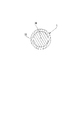
以下、図面を参照して本発明の内容を詳細に説明する。図1は、本発明の一実施形態に係る放電加工用電極線の金属合金材の断面図であり、図示のように、その放電加工用電極線は、銅60%と亜鉛40%とを混合溶解して液相(溶解温度909℃)から熱凝固(融点903℃〜900℃)を経て、銅−亜鉛二元共晶を液相から固溶相の全β(Beta)相の合金体10に溶融凝固させてなると共に、前記全β(Beta)相の合金体10の金属核を亜鉛めっきした後、直接に低温熱処理(反応温度を低温250℃以下に制御。)を施すことにより得られるものである。さらにかかる低温熱処理の処理時間を延長するように制御することにより、γ(Gamma)、ε(Epsilon)、η(Eta)相を生成させ、β(Beta)晶相に相互溶解が生じて表面に電気層が形成される固体合金を、少なくともγ(Gamma)、ε(Epsilon)、η(Eta)相を含み、低表面粗度で、迅速に切断でき、粉落ちせず、及び付着力に優れる金属合金線1を生成させる。
Hereinafter, the content of the present invention will be described in detail with reference to the drawings. FIG. 1 is a sectional view of a metal alloy material of an electrode wire for electric discharge machining according to an embodiment of the present invention. As shown in the drawing, the electrode wire for electric discharge machining is a mixture of 60% copper and 40% zinc. It melts and undergoes thermal solidification (melting point 903 ° C. to 900 ° C.) from the liquid phase (melting temperature 909 ° C.), and the copper-zinc binary eutectic is transformed into an all-β (Beta)
図2は、本発明の銅と亜鉛の平衡相を示す図である。図示のように、その中、縦軸は温度(℃)を示し、上横軸は銅(Cu)の含量比を示し、下横軸は亜鉛(Zn)の含量比を示す。当該平衡相図において、銅及び亜鉛の2種の元素を選択した後、銅と亜鉛の含量比が60:40である時(図2の標示符号10に示す斜線で標示された部分に位置する箇所)に、前記全β(Beta)相の合金体10を選択した後、前記全β(Beta)相の合金体10に対して低温熱処理を施し、平衡相によって二元共晶固体合金に対してγ(Gamma)、ε(Epsilon)、η(Eta)相を含んで存在する。そして低温熱処理融点時間を延長するように制御し(反応温度を低温420℃以下に制御してη(Eta)相を生成させ、または反応温度を低温600℃以下に制御してε(Epsilon)相を生成させ、あるいは反応温度を低温835℃以下に制御してγ(Gamma)相を生成させる。図2の標示符号1a,1b,1cで標示された部分に位置する箇所のように、被加工物の表面粗度(Ra)値は以下の表1に示す。
FIG. 2 is a diagram showing an equilibrium phase of copper and zinc according to the present invention. As shown in the figure, the vertical axis represents temperature (° C.), the upper horizontal axis represents the content ratio of copper (Cu), and the lower horizontal axis represents the content ratio of zinc (Zn). In the equilibrium phase diagram, after selecting two elements of copper and zinc, when the content ratio of copper and zinc is 60:40 (located in the hatched portion indicated by the

β(Beta)+γ(Gamma)の合金体に対して反応温度を500−400℃に制御する低温熱処理を施すことが好ましい場合、直接にγ(Gamma)相の金属合金線1に形成される銅−亜鉛合金材1aは、面粗度Ra<0.05を有し、精密かつ迅速な切断が行われ、またはβ(Beta)+γ(Gamma)の合金体に対して反応温度を400℃に制御する低温熱処理を施すことが好ましい場合、直接にε(Epsilon)相の金属合金線1に形成される銅−亜鉛合金材1bは、面粗度Ra<0.05を有し、一般的に精密な切断が行われる。あるいはβ(Beta)+γ(Gamma)の合金体に対して反応温度を250℃に制御する低温熱処理を施すことが好ましい場合、直接にη(Eta)相の金属合金線1に形成される銅−亜鉛合金材1cは、面粗度Ra<0.10を有し、粉落ちせずに精密かつ迅速な切断が行われ、そして前記全β(Beta)相の合金体10を利用すれば、金属核に対して直接に亜鉛めっきして低温熱処理を施し、少なくともγ(Gamma)、ε(Epsilon)、η(Eta)相を含む金属合金線1は、二次加工を要さずに一回の加工製造工程のみで線材の表面に電気めっきを施してめっき層を形成して完成されることから、α(Alpha)相の銅芯体にβ(Beta)相の表層を熱処理加工した後、再びγ(Gamma)相の表層に二次加工熱処理する必要があるめっき層の伝統的な繁雑な製造工程である問題を解決すると共に、その加工表層にめっきした電気めっき層の粉落ち、粗度と精密度に好ましくない欠陥が改善されることから、環境保護に寄与できる効果と、製造工程を効果的に短縮することができる効果と、その不良率を低減することができる効果が達成され、及び低表面粗度で、迅速に切断でき、粉落ちせず、及び付着力に優れる効果が達成される。
When it is preferable to perform a low temperature heat treatment for controlling the reaction temperature to 500-400 ° C. to the alloy body of β (Beta) + γ (Gamma), copper formed directly on the
なお、上記の説明は、あくまでも本発明の好適な実施例を示すものであって、本発明は、これらによって限定するものではなく、特許請求の範囲に基づいて行う等効果を生ずる発明及びバリエーションのいずれも、本発明の範囲内に含まれるべきである。 It should be noted that the above description is merely a preferred embodiment of the present invention, and the present invention is not limited thereto, and the invention and variations that produce the same effect based on the scope of the claims. Both should be included within the scope of the present invention.
従来技術
12:銅金属線
15:電気めっき層
18:銅−亜鉛固溶体
3:電極線
31:芯体
32:シース層
4:電極線
41:芯体
42:シース層
本発明
10:合金体
1:金属合金線
1a,1b,1c:銅−亜鉛合金材
Prior Art 12: Copper Metal Wire 15: Electroplating Layer 18: Copper-Zinc Solid Solution 3: Electrode Wire 31: Core Body 32: Sheath Layer 4: Electrode Wire 41: Core Body 42: Sheath Layer
Invention 10: Alloy body 1:
Claims (5)
銅60%と亜鉛40%とを混合溶解して熱凝固を経て、銅−亜鉛二元共晶を液相から固溶相の全β(Beta)相の合金体に溶融凝固させてなり、前記固溶相の全β(Beta)相の合金体に対して亜鉛めっきをした後、低温熱処理を施すことにより、前記固溶相の全β(Beta)相の合金体と亜鉛めっき層との境界にγ(Gamma)相、ε(Epsilon)相、η(Eta)相を生成させるように制御することにより、前記固溶相の全β(Beta)相と相互溶解が生じて前記固溶相の全β(Beta)相の合金体の外面に境界層が形成される固溶相の全β(Beta)相の合金体からなり、前記境界層には、少なくともγ(Gamma)相、ε(Epsilon)相、η(Eta)相を含む放電加工用電極線を生成させてなることを特徴とする放電加工用電極線の製造方法。 A method for manufacturing an electrode wire for electric discharge machining,
Copper 60% and zinc 40% are mixed and dissolved, and after thermal solidification, the copper-zinc binary eutectic is melt-solidified from a liquid phase to an alloy body of all β (Beta) phases of a solid solution phase, After the zinc alloy is plated on the solid solution phase β (Beta) phase alloy body, a low temperature heat treatment is performed, whereby the boundary between the solid solution phase all β (Beta) phase alloy body and the zinc plating layer. Γ (Gamma) phase, ε (Epsilon) phase, and η (Eta) phase are controlled to form a mutual solution with all β (Beta) phases of the solid solution phase, It consists of a solid solution phase all beta (beta) phase alloy body in which a boundary layer is formed on the outer surface of the all beta (beta) phase alloy body, and the boundary layer has at least a gamma (gamma) phase, epsilon (epsilon) ) Phase and η (Eta) phase, and an electric discharge machining electrode wire is generated. Manufacturing method of electrical discharge machining electrode wire that.
Priority Applications (1)
| Application Number | Priority Date | Filing Date | Title |
|---|---|---|---|
| JP2015158360A JP6238938B2 (en) | 2015-08-10 | 2015-08-10 | Manufacturing method of electrode wire for electric discharge machining |
Applications Claiming Priority (1)
| Application Number | Priority Date | Filing Date | Title |
|---|---|---|---|
| JP2015158360A JP6238938B2 (en) | 2015-08-10 | 2015-08-10 | Manufacturing method of electrode wire for electric discharge machining |
Publications (2)
| Publication Number | Publication Date |
|---|---|
| JP2017035753A JP2017035753A (en) | 2017-02-16 |
| JP6238938B2 true JP6238938B2 (en) | 2017-11-29 |
Family
ID=58047364
Family Applications (1)
| Application Number | Title | Priority Date | Filing Date |
|---|---|---|---|
| JP2015158360A Active JP6238938B2 (en) | 2015-08-10 | 2015-08-10 | Manufacturing method of electrode wire for electric discharge machining |
Country Status (1)
| Country | Link |
|---|---|
| JP (1) | JP6238938B2 (en) |
Cited By (1)
| Publication number | Priority date | Publication date | Assignee | Title |
|---|---|---|---|---|
| JP2020515428A (en) * | 2017-09-26 | 2020-05-28 | ▲寧▼波康▲強▼▲微▼▲電▼子技▲術▼有限公司 | Method of manufacturing textured plated electrode wire |
Family Cites Families (8)
| Publication number | Priority date | Publication date | Assignee | Title |
|---|---|---|---|---|
| GB2015909B (en) * | 1978-03-03 | 1982-12-01 | Charmilles Sa Ateliers | Electrode for spark erosion machining |
| DE19510740A1 (en) * | 1995-03-24 | 1996-10-02 | Berkenhoff Gmbh | Wire electrode and method for producing a wire electrode, in particular for the spark erosion method |
| JP2002126950A (en) * | 2000-10-23 | 2002-05-08 | Sumitomo Metal Mining Co Ltd | Manufacturing method of electrode wire for wire electric discharge machining |
| JP2002126949A (en) * | 2000-10-23 | 2002-05-08 | Sumitomo Metal Mining Co Ltd | Electrode wire for wire electric discharge machining |
| JP2003291030A (en) * | 2002-03-29 | 2003-10-14 | Oki Electric Cable Co Ltd | Electrode wire for wire electrical discharge machining |
| KR100528850B1 (en) * | 2004-02-05 | 2005-11-21 | 주식회사 풍국통상 | Multi purpose multilayer coated electrode wire for electric discharge machining and production method thereof |
| JP5042229B2 (en) * | 2007-12-10 | 2012-10-03 | 沖電線株式会社 | Electrode wire for wire electric discharge machining, its manufacturing method and its bus bar manufacturing apparatus |
| KR101292343B1 (en) * | 2011-08-08 | 2013-07-31 | 성기철 | Wire electrode for electro discharge machining and thesame methode |
-
2015
- 2015-08-10 JP JP2015158360A patent/JP6238938B2/en active Active
Cited By (1)
| Publication number | Priority date | Publication date | Assignee | Title |
|---|---|---|---|---|
| JP2020515428A (en) * | 2017-09-26 | 2020-05-28 | ▲寧▼波康▲強▼▲微▼▲電▼子技▲術▼有限公司 | Method of manufacturing textured plated electrode wire |
Also Published As
| Publication number | Publication date |
|---|---|
| JP2017035753A (en) | 2017-02-16 |
Similar Documents
| Publication | Publication Date | Title |
|---|---|---|
| KR101873953B1 (en) | High-precision zinc-based alloy electrode wire and preparation method therefor | |
| JP4012895B2 (en) | Structure of porous electrode wire for electric discharge machining | |
| US9902005B2 (en) | Low-boron-oxygen cutting line for one-way wire winding and manufacturing method thereof | |
| WO2015033896A1 (en) | Electrode wire for wire electric discharge machining, and method for producing same | |
| JP2018516769A (en) | Scale-like microstructured electrode wire material and its production method and use | |
| WO2013191022A1 (en) | Bonding member | |
| US2123384A (en) | Copper base alloy article for brazing and method of preparing it | |
| US20170014928A1 (en) | Electrode Wire for Electric Discharge Machining and Method for Manufacturing the Electrode Wire | |
| JP6238938B2 (en) | Manufacturing method of electrode wire for electric discharge machining | |
| CN110277192B (en) | Tinned copper wire and manufacturing method thereof, and insulated wire and cable | |
| US2873216A (en) | Method of chemically plating metals | |
| JP6210572B1 (en) | Copper alloy wire rod and method for producing the same | |
| JP2005206942A (en) | PRESS-BLANKING MATERIAL, AND Sn PLATING TREATMENT METHOD | |
| JP2006518005A (en) | Method for producing zinc coated electrode wire for electric discharge machine using hot dip galvanizing method | |
| TWI595951B (en) | Discharge processing electrode line | |
| KR20170014191A (en) | electric discharge processing for electrode line | |
| JP2006159304A (en) | Electrode wire for wire electric discharge machining and its manufacturing method | |
| KR101447505B1 (en) | Solder joint structure having tooth-like structure with excellent efficiency for suppressing the formation of kirkendall voids and method of manufacturing the same | |
| KR100925000B1 (en) | Electrode wire for electric discharge machining and manufacturing method thereof | |
| CN201105349Y (en) | Electrode wire for electro-discharge machining | |
| JPH02270986A (en) | Tin coated metallic sheet having excellent brightness and whisker resistance | |
| KR20130111758A (en) | Method for manufacturing diamond coated wire saw | |
| TWI612183B (en) | Electrochemical processing electrode and manufacturing method thereof | |
| EP4043135A1 (en) | Electrode wire for electrical discharge machining | |
| CN106191724A (en) | Metal alloy wire manufacture method for spark machined |
Legal Events
| Date | Code | Title | Description |
|---|---|---|---|
| A601 | Written request for extension of time |
Free format text: JAPANESE INTERMEDIATE CODE: A601 Effective date: 20161209 |
|
| A521 | Request for written amendment filed |
Free format text: JAPANESE INTERMEDIATE CODE: A523 Effective date: 20170111 |
|
| A131 | Notification of reasons for refusal |
Free format text: JAPANESE INTERMEDIATE CODE: A131 Effective date: 20170418 |
|
| A601 | Written request for extension of time |
Free format text: JAPANESE INTERMEDIATE CODE: A601 Effective date: 20170718 |
|
| A521 | Request for written amendment filed |
Free format text: JAPANESE INTERMEDIATE CODE: A523 Effective date: 20170919 |
|
| TRDD | Decision of grant or rejection written | ||
| A01 | Written decision to grant a patent or to grant a registration (utility model) |
Free format text: JAPANESE INTERMEDIATE CODE: A01 Effective date: 20171003 |
|
| A61 | First payment of annual fees (during grant procedure) |
Free format text: JAPANESE INTERMEDIATE CODE: A61 Effective date: 20171031 |
|
| R150 | Certificate of patent or registration of utility model |
Ref document number: 6238938 Country of ref document: JP Free format text: JAPANESE INTERMEDIATE CODE: R150 |
|
| R250 | Receipt of annual fees |
Free format text: JAPANESE INTERMEDIATE CODE: R250 |
|
| R250 | Receipt of annual fees |
Free format text: JAPANESE INTERMEDIATE CODE: R250 |
|
| R250 | Receipt of annual fees |
Free format text: JAPANESE INTERMEDIATE CODE: R250 |