JP6238807B2 - Engine control device - Google Patents
Engine control device Download PDFInfo
- Publication number
- JP6238807B2 JP6238807B2 JP2014061014A JP2014061014A JP6238807B2 JP 6238807 B2 JP6238807 B2 JP 6238807B2 JP 2014061014 A JP2014061014 A JP 2014061014A JP 2014061014 A JP2014061014 A JP 2014061014A JP 6238807 B2 JP6238807 B2 JP 6238807B2
- Authority
- JP
- Japan
- Prior art keywords
- exhaust gas
- recirculation
- injection
- valve
- fuel
- Prior art date
- Legal status (The legal status is an assumption and is not a legal conclusion. Google has not performed a legal analysis and makes no representation as to the accuracy of the status listed.)
- Active
Links
Images


Classifications
-
- F—MECHANICAL ENGINEERING; LIGHTING; HEATING; WEAPONS; BLASTING
- F02—COMBUSTION ENGINES; HOT-GAS OR COMBUSTION-PRODUCT ENGINE PLANTS
- F02D—CONTROLLING COMBUSTION ENGINES
- F02D37/00—Non-electrical conjoint control of two or more functions of engines, not otherwise provided for
- F02D37/02—Non-electrical conjoint control of two or more functions of engines, not otherwise provided for one of the functions being ignition
-
- F—MECHANICAL ENGINEERING; LIGHTING; HEATING; WEAPONS; BLASTING
- F01—MACHINES OR ENGINES IN GENERAL; ENGINE PLANTS IN GENERAL; STEAM ENGINES
- F01P—COOLING OF MACHINES OR ENGINES IN GENERAL; COOLING OF INTERNAL-COMBUSTION ENGINES
- F01P3/00—Liquid cooling
- F01P3/20—Cooling circuits not specific to a single part of engine or machine
-
- F—MECHANICAL ENGINEERING; LIGHTING; HEATING; WEAPONS; BLASTING
- F01—MACHINES OR ENGINES IN GENERAL; ENGINE PLANTS IN GENERAL; STEAM ENGINES
- F01P—COOLING OF MACHINES OR ENGINES IN GENERAL; COOLING OF INTERNAL-COMBUSTION ENGINES
- F01P5/00—Pumping cooling-air or liquid coolants
- F01P5/10—Pumping liquid coolant; Arrangements of coolant pumps
-
- F—MECHANICAL ENGINEERING; LIGHTING; HEATING; WEAPONS; BLASTING
- F02—COMBUSTION ENGINES; HOT-GAS OR COMBUSTION-PRODUCT ENGINE PLANTS
- F02B—INTERNAL-COMBUSTION PISTON ENGINES; COMBUSTION ENGINES IN GENERAL
- F02B31/00—Modifying induction systems for imparting a rotation to the charge in the cylinder
- F02B31/04—Modifying induction systems for imparting a rotation to the charge in the cylinder by means within the induction channel, e.g. deflectors
- F02B31/06—Movable means, e.g. butterfly valves
-
- F—MECHANICAL ENGINEERING; LIGHTING; HEATING; WEAPONS; BLASTING
- F02—COMBUSTION ENGINES; HOT-GAS OR COMBUSTION-PRODUCT ENGINE PLANTS
- F02D—CONTROLLING COMBUSTION ENGINES
- F02D13/00—Controlling the engine output power by varying inlet or exhaust valve operating characteristics, e.g. timing
- F02D13/02—Controlling the engine output power by varying inlet or exhaust valve operating characteristics, e.g. timing during engine operation
- F02D13/0203—Variable control of intake and exhaust valves
- F02D13/0215—Variable control of intake and exhaust valves changing the valve timing only
- F02D13/0219—Variable control of intake and exhaust valves changing the valve timing only by shifting the phase, i.e. the opening periods of the valves are constant
-
- F—MECHANICAL ENGINEERING; LIGHTING; HEATING; WEAPONS; BLASTING
- F02—COMBUSTION ENGINES; HOT-GAS OR COMBUSTION-PRODUCT ENGINE PLANTS
- F02D—CONTROLLING COMBUSTION ENGINES
- F02D13/00—Controlling the engine output power by varying inlet or exhaust valve operating characteristics, e.g. timing
- F02D13/02—Controlling the engine output power by varying inlet or exhaust valve operating characteristics, e.g. timing during engine operation
- F02D13/0261—Controlling the valve overlap
-
- F—MECHANICAL ENGINEERING; LIGHTING; HEATING; WEAPONS; BLASTING
- F02—COMBUSTION ENGINES; HOT-GAS OR COMBUSTION-PRODUCT ENGINE PLANTS
- F02D—CONTROLLING COMBUSTION ENGINES
- F02D21/00—Controlling engines characterised by their being supplied with non-airborne oxygen or other non-fuel gas
- F02D21/06—Controlling engines characterised by their being supplied with non-airborne oxygen or other non-fuel gas peculiar to engines having other non-fuel gas added to combustion air
- F02D21/08—Controlling engines characterised by their being supplied with non-airborne oxygen or other non-fuel gas peculiar to engines having other non-fuel gas added to combustion air the other gas being the exhaust gas of engine
-
- F—MECHANICAL ENGINEERING; LIGHTING; HEATING; WEAPONS; BLASTING
- F02—COMBUSTION ENGINES; HOT-GAS OR COMBUSTION-PRODUCT ENGINE PLANTS
- F02D—CONTROLLING COMBUSTION ENGINES
- F02D41/00—Electrical control of supply of combustible mixture or its constituents
- F02D41/0025—Controlling engines characterised by use of non-liquid fuels, pluralities of fuels, or non-fuel substances added to the combustible mixtures
- F02D41/0047—Controlling exhaust gas recirculation [EGR]
- F02D41/005—Controlling exhaust gas recirculation [EGR] according to engine operating conditions
-
- F—MECHANICAL ENGINEERING; LIGHTING; HEATING; WEAPONS; BLASTING
- F02—COMBUSTION ENGINES; HOT-GAS OR COMBUSTION-PRODUCT ENGINE PLANTS
- F02D—CONTROLLING COMBUSTION ENGINES
- F02D41/00—Electrical control of supply of combustible mixture or its constituents
- F02D41/30—Controlling fuel injection
-
- F—MECHANICAL ENGINEERING; LIGHTING; HEATING; WEAPONS; BLASTING
- F02—COMBUSTION ENGINES; HOT-GAS OR COMBUSTION-PRODUCT ENGINE PLANTS
- F02D—CONTROLLING COMBUSTION ENGINES
- F02D41/00—Electrical control of supply of combustible mixture or its constituents
- F02D41/30—Controlling fuel injection
- F02D41/32—Controlling fuel injection of the low pressure type
- F02D41/34—Controlling fuel injection of the low pressure type with means for controlling injection timing or duration
- F02D41/345—Controlling injection timing
-
- F—MECHANICAL ENGINEERING; LIGHTING; HEATING; WEAPONS; BLASTING
- F02—COMBUSTION ENGINES; HOT-GAS OR COMBUSTION-PRODUCT ENGINE PLANTS
- F02D—CONTROLLING COMBUSTION ENGINES
- F02D41/00—Electrical control of supply of combustible mixture or its constituents
- F02D41/30—Controlling fuel injection
- F02D41/38—Controlling fuel injection of the high pressure type
- F02D41/3809—Common rail control systems
- F02D41/3836—Controlling the fuel pressure
-
- F—MECHANICAL ENGINEERING; LIGHTING; HEATING; WEAPONS; BLASTING
- F02—COMBUSTION ENGINES; HOT-GAS OR COMBUSTION-PRODUCT ENGINE PLANTS
- F02D—CONTROLLING COMBUSTION ENGINES
- F02D41/00—Electrical control of supply of combustible mixture or its constituents
- F02D41/30—Controlling fuel injection
- F02D41/38—Controlling fuel injection of the high pressure type
- F02D41/40—Controlling fuel injection of the high pressure type with means for controlling injection timing or duration
- F02D41/401—Controlling injection timing
-
- F—MECHANICAL ENGINEERING; LIGHTING; HEATING; WEAPONS; BLASTING
- F02—COMBUSTION ENGINES; HOT-GAS OR COMBUSTION-PRODUCT ENGINE PLANTS
- F02D—CONTROLLING COMBUSTION ENGINES
- F02D41/00—Electrical control of supply of combustible mixture or its constituents
- F02D41/30—Controlling fuel injection
- F02D41/38—Controlling fuel injection of the high pressure type
- F02D41/40—Controlling fuel injection of the high pressure type with means for controlling injection timing or duration
- F02D41/402—Multiple injections
-
- F—MECHANICAL ENGINEERING; LIGHTING; HEATING; WEAPONS; BLASTING
- F02—COMBUSTION ENGINES; HOT-GAS OR COMBUSTION-PRODUCT ENGINE PLANTS
- F02M—SUPPLYING COMBUSTION ENGINES IN GENERAL WITH COMBUSTIBLE MIXTURES OR CONSTITUENTS THEREOF
- F02M26/00—Engine-pertinent apparatus for adding exhaust gases to combustion-air, main fuel or fuel-air mixture, e.g. by exhaust gas recirculation [EGR] systems
- F02M26/13—Arrangement or layout of EGR passages, e.g. in relation to specific engine parts or for incorporation of accessories
- F02M26/14—Arrangement or layout of EGR passages, e.g. in relation to specific engine parts or for incorporation of accessories in relation to the exhaust system
- F02M26/15—Arrangement or layout of EGR passages, e.g. in relation to specific engine parts or for incorporation of accessories in relation to the exhaust system in relation to engine exhaust purifying apparatus
-
- F—MECHANICAL ENGINEERING; LIGHTING; HEATING; WEAPONS; BLASTING
- F02—COMBUSTION ENGINES; HOT-GAS OR COMBUSTION-PRODUCT ENGINE PLANTS
- F02M—SUPPLYING COMBUSTION ENGINES IN GENERAL WITH COMBUSTIBLE MIXTURES OR CONSTITUENTS THEREOF
- F02M26/00—Engine-pertinent apparatus for adding exhaust gases to combustion-air, main fuel or fuel-air mixture, e.g. by exhaust gas recirculation [EGR] systems
- F02M26/13—Arrangement or layout of EGR passages, e.g. in relation to specific engine parts or for incorporation of accessories
- F02M26/22—Arrangement or layout of EGR passages, e.g. in relation to specific engine parts or for incorporation of accessories with coolers in the recirculation passage
- F02M26/23—Layout, e.g. schematics
- F02M26/28—Layout, e.g. schematics with liquid-cooled heat exchangers
-
- F—MECHANICAL ENGINEERING; LIGHTING; HEATING; WEAPONS; BLASTING
- F02—COMBUSTION ENGINES; HOT-GAS OR COMBUSTION-PRODUCT ENGINE PLANTS
- F02P—IGNITION, OTHER THAN COMPRESSION IGNITION, FOR INTERNAL-COMBUSTION ENGINES; TESTING OF IGNITION TIMING IN COMPRESSION-IGNITION ENGINES
- F02P15/00—Electric spark ignition having characteristics not provided for in, or of interest apart from, groups F02P1/00 - F02P13/00 and combined with layout of ignition circuits
- F02P15/08—Electric spark ignition having characteristics not provided for in, or of interest apart from, groups F02P1/00 - F02P13/00 and combined with layout of ignition circuits having multiple-spark ignition, i.e. ignition occurring simultaneously at different places in one engine cylinder or in two or more separate engine cylinders
-
- F—MECHANICAL ENGINEERING; LIGHTING; HEATING; WEAPONS; BLASTING
- F02—COMBUSTION ENGINES; HOT-GAS OR COMBUSTION-PRODUCT ENGINE PLANTS
- F02P—IGNITION, OTHER THAN COMPRESSION IGNITION, FOR INTERNAL-COMBUSTION ENGINES; TESTING OF IGNITION TIMING IN COMPRESSION-IGNITION ENGINES
- F02P5/00—Advancing or retarding ignition; Control therefor
- F02P5/04—Advancing or retarding ignition; Control therefor automatically, as a function of the working conditions of the engine or vehicle or of the atmospheric conditions
- F02P5/145—Advancing or retarding ignition; Control therefor automatically, as a function of the working conditions of the engine or vehicle or of the atmospheric conditions using electrical means
- F02P5/15—Digital data processing
- F02P5/1502—Digital data processing using one central computing unit
- F02P5/1516—Digital data processing using one central computing unit with means relating to exhaust gas recirculation, e.g. turbo
-
- F—MECHANICAL ENGINEERING; LIGHTING; HEATING; WEAPONS; BLASTING
- F02—COMBUSTION ENGINES; HOT-GAS OR COMBUSTION-PRODUCT ENGINE PLANTS
- F02D—CONTROLLING COMBUSTION ENGINES
- F02D41/00—Electrical control of supply of combustible mixture or its constituents
- F02D41/0002—Controlling intake air
- F02D2041/0015—Controlling intake air for engines with means for controlling swirl or tumble flow, e.g. by using swirl valves
-
- F—MECHANICAL ENGINEERING; LIGHTING; HEATING; WEAPONS; BLASTING
- F02—COMBUSTION ENGINES; HOT-GAS OR COMBUSTION-PRODUCT ENGINE PLANTS
- F02D—CONTROLLING COMBUSTION ENGINES
- F02D41/00—Electrical control of supply of combustible mixture or its constituents
- F02D41/02—Circuit arrangements for generating control signals
- F02D41/14—Introducing closed-loop corrections
- F02D41/1438—Introducing closed-loop corrections using means for determining characteristics of the combustion gases; Sensors therefor
- F02D41/1444—Introducing closed-loop corrections using means for determining characteristics of the combustion gases; Sensors therefor characterised by the characteristics of the combustion gases
- F02D2041/1472—Introducing closed-loop corrections using means for determining characteristics of the combustion gases; Sensors therefor characterised by the characteristics of the combustion gases the characteristics being a humidity or water content of the exhaust gases
-
- F—MECHANICAL ENGINEERING; LIGHTING; HEATING; WEAPONS; BLASTING
- F02—COMBUSTION ENGINES; HOT-GAS OR COMBUSTION-PRODUCT ENGINE PLANTS
- F02D—CONTROLLING COMBUSTION ENGINES
- F02D2200/00—Input parameters for engine control
- F02D2200/02—Input parameters for engine control the parameters being related to the engine
- F02D2200/06—Fuel or fuel supply system parameters
- F02D2200/0602—Fuel pressure
-
- F—MECHANICAL ENGINEERING; LIGHTING; HEATING; WEAPONS; BLASTING
- F02—COMBUSTION ENGINES; HOT-GAS OR COMBUSTION-PRODUCT ENGINE PLANTS
- F02D—CONTROLLING COMBUSTION ENGINES
- F02D2200/00—Input parameters for engine control
- F02D2200/02—Input parameters for engine control the parameters being related to the engine
- F02D2200/06—Fuel or fuel supply system parameters
- F02D2200/0606—Fuel temperature
-
- Y—GENERAL TAGGING OF NEW TECHNOLOGICAL DEVELOPMENTS; GENERAL TAGGING OF CROSS-SECTIONAL TECHNOLOGIES SPANNING OVER SEVERAL SECTIONS OF THE IPC; TECHNICAL SUBJECTS COVERED BY FORMER USPC CROSS-REFERENCE ART COLLECTIONS [XRACs] AND DIGESTS
- Y02—TECHNOLOGIES OR APPLICATIONS FOR MITIGATION OR ADAPTATION AGAINST CLIMATE CHANGE
- Y02T—CLIMATE CHANGE MITIGATION TECHNOLOGIES RELATED TO TRANSPORTATION
- Y02T10/00—Road transport of goods or passengers
- Y02T10/10—Internal combustion engine [ICE] based vehicles
- Y02T10/12—Improving ICE efficiencies
-
- Y—GENERAL TAGGING OF NEW TECHNOLOGICAL DEVELOPMENTS; GENERAL TAGGING OF CROSS-SECTIONAL TECHNOLOGIES SPANNING OVER SEVERAL SECTIONS OF THE IPC; TECHNICAL SUBJECTS COVERED BY FORMER USPC CROSS-REFERENCE ART COLLECTIONS [XRACs] AND DIGESTS
- Y02—TECHNOLOGIES OR APPLICATIONS FOR MITIGATION OR ADAPTATION AGAINST CLIMATE CHANGE
- Y02T—CLIMATE CHANGE MITIGATION TECHNOLOGIES RELATED TO TRANSPORTATION
- Y02T10/00—Road transport of goods or passengers
- Y02T10/10—Internal combustion engine [ICE] based vehicles
- Y02T10/40—Engine management systems
Description
本発明は車両等に搭載されるエンジンの制御装置に係り、特に燃焼室内で燃料を燃焼させて動力を取り出す内燃機関の制御に適した制御装置に関する。 The present invention relates to a control device for an engine mounted on a vehicle or the like, and more particularly to a control device suitable for controlling an internal combustion engine that extracts power by burning fuel in a combustion chamber.
現在の自動車は、環境保全と資源有効活用の観点から高効率化と排気清浄化とを強く要求されている。高効率化の手段として、筒内直噴燃料供給装置と排気再循環装置とを備えるガソリンエンジンの開発が進められている。筒内直噴燃料供給装置は燃料噴射弁(以下、インジェクタと呼ぶ)を用いて燃焼室内に燃料噴射を直接実施するものであり、燃焼室内を冷却することで異常燃焼の抑制効果が得られる。排気再循環装置はガソリンエンジンから排出される排気を吸気管に還流し再度燃焼室内に流入させ燃焼するものであり、燃焼室内のガス比熱を増加させガス温度を低減することで異常燃焼の抑制が得られる。上記異常燃焼の抑制効果により、ガソリンエンジンの高圧縮比化あるいはダウンサイジングが可能となり高効率化の効果が得られる。筒内直噴燃料供給装置と排気再循環装置とを備えるガソリンエンジンでは、排気再循環装置による排気還流量および排気還流ガス温度の変化によって燃焼室内で実施される燃焼が変動あるいはばらつく等(以下,燃焼変動と呼ぶ)の課題がある。 Current automobiles are strongly required to be highly efficient and clean exhaust from the viewpoint of environmental conservation and effective utilization of resources. Development of a gasoline engine equipped with an in-cylinder direct injection fuel supply device and an exhaust gas recirculation device has been promoted as a means for improving efficiency. The in-cylinder direct injection fuel supply device directly injects fuel into the combustion chamber using a fuel injection valve (hereinafter referred to as an injector), and the effect of suppressing abnormal combustion can be obtained by cooling the combustion chamber. The exhaust gas recirculation system recirculates the exhaust gas discharged from the gasoline engine to the intake pipe and flows it again into the combustion chamber for combustion. By suppressing the gas temperature by increasing the gas specific heat in the combustion chamber, abnormal combustion can be suppressed. can get. Due to the effect of suppressing the abnormal combustion, a high compression ratio or downsizing of the gasoline engine is possible, and the effect of high efficiency can be obtained. In a gasoline engine equipped with an in-cylinder direct injection fuel supply device and an exhaust gas recirculation device, the combustion performed in the combustion chamber fluctuates or varies due to changes in the exhaust gas recirculation amount and the exhaust gas recirculation gas temperature by the exhaust gas recirculation device. (It is called combustion fluctuation).
そのため、例えば特許2611217号公報(特許文献1)には、内燃機関の運転状態に応じて燃料噴射時期を定め、この燃料噴射時期に基づいて内燃機関の各気筒独立に燃料噴射を行う燃料噴射制御手段を備えると共に、排気系から吸気系へ排気ガスを再循環する排気ガス再循環装置を備えた燃料噴射時期制御装置において、排気ガスの再循環の実行時には上記燃料噴射時期を遅角させ、排気ガスの再循環の停止時には上記燃料噴射時期を進角させる噴射時期変更手段を備えた燃料噴射時期制御装置が開示されている(特許請求の範囲参照)。 For this reason, for example, Japanese Patent No. 2611217 (Patent Document 1) discloses a fuel injection control in which a fuel injection timing is determined according to the operating state of the internal combustion engine, and fuel is independently injected into each cylinder of the internal combustion engine based on this fuel injection timing. And a fuel injection timing control device including an exhaust gas recirculation device that recirculates exhaust gas from the exhaust system to the intake system, and delays the fuel injection timing when exhaust gas recirculation is executed, A fuel injection timing control device having an injection timing changing means for advancing the fuel injection timing when gas recirculation is stopped is disclosed (see claims).
特許文献1の燃料噴射時期制御装置では、排気再循環時に噴射時期を遅角させるため、点火栓近傍に燃料を噴射することになる。この場合、燃料と空気との混合が低下するという課題が生じる。さらに燃焼室内の圧力は圧縮途上であり、吸気行程に比べ高くなる。したがってインジェクタから噴射される燃料は、空気抵抗と、燃料の圧力(以下、燃圧)と燃焼室内圧力との差圧が小さくなることとにより、噴霧貫徹力が低下し、噴霧の飛距離(以下、ペネトレーションと呼ぶ)が短くなる。その結果、噴射時期を遅角したが故に点火栓近傍に燃料が到達しにくくなる。かつペネトレーションは燃焼室内ガス温度、吸入空気温度、排気還流ガス温度のいずれかが増加しても短くなる。これは燃料がより高温のガス中に噴射されることで微粒化および気化が促進され、噴霧貫徹力が低下するためである。このように噴射時期を遅角させることで、点火栓近傍に燃料が到達しにくくなり、点火が困難になって燃焼変動が悪化する可能性がある。これにより、内燃機関の効率が低下し、また排気が悪化するという課題が生じる。
In the fuel injection timing control device of
本発明は上記課題を鑑みてなされたものであり、排気再循環時に、燃料と空気との混合を促進することができ、その結果ガソリンエンジンの燃焼変動を抑制し、効率と排気清浄化とを両立することができるエンジン制御装置を提供することにある。 The present invention has been made in view of the above problems, and can promote the mixing of fuel and air during exhaust gas recirculation, thereby suppressing combustion fluctuations in a gasoline engine and improving efficiency and exhaust purification. An object of the present invention is to provide an engine control device that can achieve both.
上記目的を達成するために、本発明は、筒内へ直接燃料を噴射する噴射装置と、排気ガスを吸気側へ還流する還流装置とを備えるエンジンを制御するエンジン制御装置において、前記還流装置によって還流される還流排気ガス温度が高い場合は低い場合と比較して、あるいは前記還流装置によって還流される還流排気ガス量が多い場合は少ない場合と比較して、前記噴射装置の燃料噴射時期を進角させると共に、吸気上死点から圧縮上死点までの期間に前記噴射装置が分割多段噴射する回数を減少させる。 In order to achieve the above object, the present invention provides an engine control apparatus for controlling an engine including an injection device that directly injects fuel into a cylinder and a recirculation device that recirculates exhaust gas to the intake side. When the temperature of the recirculated exhaust gas to be recirculated is high, the fuel injection timing of the injector is advanced compared to when it is low or when the amount of recirculated exhaust gas recirculated by the recirculation device is large. with angularly, the injector is small is to decrease the number of times of split multi-stage injection in the period until the compression top dead center from the intake top dead center.
排気循環量の増加、あるいは排気還流ガス温度の増加に応じて、噴射時期を進角する、燃圧を増加する、吸気上死点から圧縮上死点にかけての分割多段噴射の回数を減少する、或いは分割多段噴射の噴射間隔を減少することにより、ペネトレーションを長くすることができる。これにより、燃料を燃焼室内に広く分布させることができ、燃料と空気との混合を促進する。その結果ガソリンエンジンの燃焼変動を抑制し、効率と排気清浄化とを両立して実現することができる。 Advancing the injection timing, increasing the fuel pressure, decreasing the number of split multistage injections from the intake top dead center to the compression top dead center according to an increase in the exhaust gas circulation amount or an increase in the exhaust gas recirculation gas temperature, or By reducing the injection interval of the divided multi-stage injection, the penetration can be lengthened. Thereby, fuel can be widely distributed in the combustion chamber, and mixing of fuel and air is promoted. As a result, combustion fluctuations in the gasoline engine can be suppressed, and both efficiency and exhaust purification can be achieved.
上記した以外の課題、構成及び効果は、以下の実施形態の説明により明らかにされる。 Problems, configurations, and effects other than those described above will be clarified by the following description of embodiments.
以下、本発明に係る実施形態について説明する Hereinafter, embodiments according to the present invention will be described.
以下、図1から図13を用いて、本実施形態に係るエンジン制御装置の構成および動作について説明する。 Hereinafter, the configuration and operation of the engine control apparatus according to the present embodiment will be described with reference to FIGS. 1 to 13.
図1から図13は、本発明の一実施形態に係り、筒内へ直接燃料を噴射する噴射装置と、排気ガスを吸気側へ還流する還流装置とを備えるガソリンエンジンの制御装置において、前記還流装置によって還流される排気ガス温度が高い場合は低い場合と比較して、あるいは前記還流装置によって還流される排気ガス量が多い場合は少ない場合と比較して、前記噴射装置の燃料噴射時期の進角と、前記噴射装置へ供給する燃料圧力の増加と、吸気上死点から圧縮上死点までの期間に前記噴射装置が分割多段噴射する回数の減少と、前記分割多段噴射における各噴射間隔の減少との内、少なくとも1つを実行させるエンジン制御装置を、自動車用ガソリンエンジンに適用したシステムの構成図である。 FIG. 1 to FIG. 13 relate to an embodiment of the present invention, in a gasoline engine control device comprising an injection device that directly injects fuel into a cylinder and a recirculation device that recirculates exhaust gas to the intake side. When the temperature of the exhaust gas recirculated by the device is high, the fuel injection timing of the injection device is advanced compared to when it is low or when the amount of exhaust gas recirculated by the recirculation device is large. An angle, an increase in fuel pressure supplied to the injection device, a decrease in the number of divided multistage injections during the period from the intake top dead center to the compression top dead center, and each injection interval in the divided multistage injection. It is a block diagram of a system in which an engine control device that executes at least one of the reductions is applied to a gasoline engine for automobiles.
図1は本実施形態に係る自動車用エンジンシステムのシステム構成図である。エンジン100は、火花点火式燃焼を実施する自動車用エンジンである。吸入空気量を計測するエアフロセンサ3と、吸気管圧力を調整するスロットル5と、吸入空気温度および湿度検出器の一態様であって吸入空気の温度および湿度を計測する吸気温湿度センサ4と、吸気管内の面積を可変にするタンブル弁6とが、吸気管11の各々の適宜位置に備えられている。エアフロセンサ3は吸入空気圧力センサとしてもよい。
FIG. 1 is a system configuration diagram of an automobile engine system according to the present embodiment. The
またエンジン100には燃焼室16の中に燃料を噴射する燃料噴射装置(以下、インジェクタと呼ぶ)7と、点火エネルギを供給する点火プラグ18とが備えられ、燃焼室11に流入する吸入空気と排出する排気を調整する可変動弁12(吸気弁12a、排気弁12b)とがエンジン100の各々の適宜位置に備えられている。インジェクタ7と連結することで燃料を供給するコモンレール9と、コモンレール9に燃料を圧送するための燃料ポンプ8と、燃料ポンプ8に燃料を供給する燃料配管10とが、エンジン100の各々の適宜位置に備えられている。
Further, the
また燃料圧力検出器の一態様であって燃料の圧力を計測する燃料圧力センサ30がコモンレール9の適宜位置に備えられている。ここで燃料圧力センサ30は燃料温度センサであってもよい。点火プラグ18は点火コイル19と接続され点火コイル19によって点火エネルギを制御される。
In addition, a
さらに排気を浄化する三元触媒22と、排気温検出器の一態様であって三元触媒22の上流側にて排気の温度を計測する排気温センサ23と、空燃比検出器の一態様であって三元触媒22の上流側にて排気の空燃比を検出する空燃比センサ24と、吸気管11へ連結される排気還流管27とが、排気管21の各々の適宜位置に備えられている。空燃比センサ24は酸素濃度センサとしてもよい。
Further, a three-
また排気還流量を調整するEGR弁25と、還流ガス温度を検出する還流ガス温度検出器の一態様であって還流ガス温度を調整するEGRクーラ26とが、排気還流管27の適宜位置に備えられている。EGR弁25は、例えばバタフライ形状の弁やニードル弁などで構成することができる。またEGRクーラ26は還流ガス温度の温度調整を実施するための冷却水の出入口を有し、冷却水の流量を制御するための冷却水ポンプ28と冷却水流路切替弁29とがエンジン100の各々の適宜位置に備えられている。EGRクーラ26で用いられる冷却水或いは冷媒としては、エンジンを冷却するための冷却水或いは冷媒が用いられる。
An
またクランクシャフト14にはクランクシャフト14の角度および回転速度およびピストン13の移動速度を検出するためのクランク角センサ15が備えられている。またエンジン内部のイオン量を検出するイオンセンサ20がエンジン100の適宜位置に備えられている。またイオンセンサ20はエンジン(燃焼室)内部の圧力を検出する圧力センサであってもよい。
The
またエンジン100内部の冷却水温度を検出する冷却水温センサ17がエンジン100の適宜位置に備えられている。エアフロセンサ3と吸気温湿度センサ4とクランク角センサ15と冷却水温センサ17とイオンセンサ20と排気温センサ23と空燃比センサ24とEGRクーラ26と燃料圧力センサ30とから得られる信号は、エンジンコントロールユニット(以下、ECU1)に送られる。
A
上記の信号の他、ECU1には、アクセル開度センサ2から得られる信号が送られる。アクセル開度センサ2はアクセルペダルの踏み込み量、すなわちアクセル開度を検出する。ECU1はアクセル開度センサ2の出力信号に基いて要求トルクを演算する。すなわちアクセル開度センサ2はエンジン100への要求トルクを検出する要求トルク検出センサとして用いられる。
In addition to the above signals, a signal obtained from the
ECU1はクランク角センサ15の出力信号に基いてクランクシャフト14の角度および回転速度およびピストン13の移動速度を演算する。ECU1は前記各種センサの出力から得られるエンジン100の運転状態に基いてスロットル5の開度とタンブル弁6の開度とインジェクタ7の噴射信号と燃料ポンプ8の駆動信号と可変動弁12の弁開閉タイミングと点火コイル19の点火信号とEGR弁28の開度と冷却水制御として冷却水ポンプ28及び冷却水切替弁の駆動信号などの、エンジン100の主要な作動量を決める信号(指令)を好適に演算する。
The
ECU1で演算されたスロットル開度はスロットル駆動信号としてスロットル5へ送られる。ECU1で演算されたタンブル弁開度はタンブル弁駆動信号としてタンブル弁6へ送られる。ECU1で演算された噴射信号はインジェクタ開弁パルス信号に変換されインジェクタ7に送られる。ECU1で演算された燃料ポンプ駆動信号は燃料ポンプ8へ送られる。ECU1で演算された弁開閉タイミングは可変動弁駆動信号として可変動弁12へ送られる。ECU1で演算された点火信号で点火されるように点火信号が点火コイル19に送られる。ECU1で演算されたEGR弁開度はEGR弁駆動信号としてEGR弁25へ送られる。ECU1で演算された冷却水制御信号は冷却水制御駆動信号として冷却水ポンプ28と冷却水流路切替弁29とへ送られる。
The throttle opening calculated by the
吸気管11から可変動弁12の吸気弁12aを経て燃焼室16内に流入した空気と排気管21からEGR弁25とEGRクーラ26を経て再循環する再循環ガスとの混合気に対し、燃料を噴射して可燃混合気を形成する。可燃混合気は所定の点火タイミングで点火コイル19により点火エネルギを供給された点火プラグ18から発生される火花により爆発し、その燃焼圧によりピストン13を押し下げてエンジン100の駆動力となる。爆発後の排気は排気管21を経て三元触媒22に送られ排気成分は三元触媒22内で浄化された後、排出される。エンジン100は自動車に搭載されており、自動車の走行状態に関する情報はECU1に送られる。
Fuel is produced against a mixture of air flowing into the
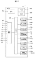
図2は本実施形態に係るECU1の構成を示すシステムブロック図である。アクセル開度センサ2、エアフロセンサ3、吸気温湿度センサ4、クランク角センサ15、冷却水温センサ17、イオンセンサ20、排気温センサ23、空燃比センサ24、EGRクーラ26に備えられた還流ガス温度検出器26a、及び燃料圧力センサ30の出力信号は、ECU1の入力回路50aに入力される。ただし入力信号はこれらだけに限られない。入力された各センサの入力信号は、入出力ポート50bに送られる。入出力ポート50bに送られた値はRAM50cに保管されCPU50eで演算処理される。演算処理内容を記述した制御プログラムはROM50dに予め書き込まれている。制御プログラムに従って演算された各アクチュエータの作動量を示す値は、RAM50cに保管された後、入出力ポート50bの出力ポートに送られ各駆動回路を経て各アクチュエータに送られる。本実施形態の場合は駆動回路としてスロットル駆動回路50f、タンブル弁駆動回路50g、インジェクタ駆動回路50h、燃料ポンプ駆動回路50i、可変動弁駆動回路50j、点火信号出力回路50k、EGR弁駆動回路50l、及び冷却水制御駆動回路50mがある。各回路はスロットル5、タンブル弁6、インジェクタ7、燃料ポンプ8、可変動弁12、点火コイル19、EGR弁25、及び冷却水ポンプあるいは冷却水流路切替弁29を制御する。本実施形態においてはECU1内に前記駆動回路を備えているがこれに限るものではなく、前記駆動回路のいずれかをECU1内に備え、その他の駆動回路をECU1外に備えるものであってもよい。
FIG. 2 is a system block diagram showing the configuration of the
図3Aは本実施形態に係るスロットルの特性を示す特性図である。図3Bは本実施形態に係る可変動弁の特性を示す特性図である。図3Aの縦軸は吸入空気量QAを示し、横軸はスロットル開度TPOを示しており、スロットル開度TPOに対応する吸入空気量QAの特性を示す。スロットル開度TPOの増加に伴い吸入空気量QAを増加することが可能である。図3Bの縦軸はバルブリフト量VLを示し、横軸は経過時間を示しており、経過時間に対応するエンジン100の行程(膨張、排気、吸気、圧縮)を図3Bの下部に示す。排気弁12bは排気膨張行程から吸気行程に渡って開閉動作が可能であり、吸気弁12aは排気工程から圧縮行程に渡って開閉動作が可能である。
FIG. 3A is a characteristic diagram showing the characteristics of the throttle according to the present embodiment. FIG. 3B is a characteristic diagram showing characteristics of the variable valve according to the present embodiment. The vertical axis in FIG. 3A represents the intake air amount QA, and the horizontal axis represents the throttle opening TPO, which shows the characteristics of the intake air amount QA corresponding to the throttle opening TPO. As the throttle opening TPO increases, the intake air amount QA can be increased. The vertical axis in FIG. 3B indicates the valve lift amount VL, the horizontal axis indicates the elapsed time, and the stroke (expansion, exhaust, intake, compression) of the
排気バルブリフト量VLが増加し始まるタイミングを排気弁開タイミング、その後減少し零となるタイミングを排気弁閉タイミングと定義する。排気弁開タイミングと排気弁閉タイミングとがそれぞれ時間軸で遅くなるよう可変機構を備えており、可変機構による可変量を排気弁遅角度VTCEと定義する。 The timing at which the exhaust valve lift amount VL begins to increase is defined as the exhaust valve opening timing, and the timing after which the exhaust valve lift amount VL decreases to zero is defined as the exhaust valve closing timing. A variable mechanism is provided so that the exhaust valve opening timing and the exhaust valve closing timing are delayed on the time axis, and the variable amount by the variable mechanism is defined as the exhaust valve retard angle VTCE.
吸気バルブリフト量VLが増加し始まるタイミングを吸気弁開タイミング、その後減少し零となるタイミングを吸気弁閉タイミングと定義する。吸気弁開タイミングと吸気弁閉タイミングとがそれぞれ時間軸で早くなるよう可変機構を備えており,可変機構による可変量を吸気弁進角度VTCIと定義する。すなわち、吸気弁12aと排気弁12bとは、それぞれ弁の開閉タイミングを変えられるように可変機構を備えている。
The timing at which the intake valve lift amount VL begins to increase is defined as the intake valve opening timing, and the timing at which it subsequently decreases and becomes zero is defined as the intake valve closing timing. A variable mechanism is provided so that the intake valve opening timing and the intake valve closing timing become earlier on the time axis, and the variable amount by the variable mechanism is defined as the intake valve advance angle VTCI. That is, the intake valve 12a and the
本実施形態においては吸気弁12aおよび排気弁12bにバルブリフト量VLのプロフィールを連続的あるいは段階的に変更する可変機能を備えているが、これに限るものではなく、吸気弁12aのみに有しても良い。さらにバルブリフト量VLを可変とする機構を有しても良い。以上の可変動弁12とスロットル5との制御により、燃焼室16の中の吸入空気量QAの量を調整する。
In the present embodiment, the intake valve 12a and the
図4Aは本実施形態に係るEGR弁の特性を示す特性図である。図4Bは本実施形態に係る冷却水ポンプ及び冷却水流路切替弁の特性を示す特性図である。図4Aの縦軸はEGR流量QEを示し、横軸はEGR弁開度EPOを示しており、EGR弁開度EPOに対応するEGR流量QEの特性を示す。EGR弁開度EPOの増加に伴いEGR流量QEを増加することが可能である。図4Bの縦軸は還流ガス温度TEを示し、横軸は冷却水ポンプ駆動電流と冷却水流路切替弁開度とを示しており、冷却水ポンプ駆動電流と冷却水流路切替弁開度とに対応する還流ガス温度TEの特性を示す。冷却水ポンプ駆動電流の増加あるいは冷却水流路切替弁開度の増加に伴い還流ガス温度TEを減少させることが可能である。以上のEGR弁25と冷却水ポンプ28と冷却水流路切替弁29との制御によりEGRクーラ26の中のEGR流量QEと還流ガス温度TEとを調整する。冷却水ポンプ28と冷却水流路切替弁29とは還流排気ガス温度を調整する還流ガス温度調整装置を構成する。この還流ガス温度調整装置で用いられる冷却水或いは冷媒としては、エンジンを冷却するための冷却水或いは冷媒が用いられる。
FIG. 4A is a characteristic diagram showing characteristics of the EGR valve according to the present embodiment. FIG. 4B is a characteristic diagram showing characteristics of the cooling water pump and the cooling water flow path switching valve according to the present embodiment. In FIG. 4A, the vertical axis represents the EGR flow rate QE, and the horizontal axis represents the EGR valve opening degree EPO, indicating the characteristic of the EGR flow rate QE corresponding to the EGR valve opening degree EPO. The EGR flow rate QE can be increased as the EGR valve opening EPO increases. The vertical axis in FIG. 4B indicates the reflux gas temperature TE, and the horizontal axis indicates the cooling water pump drive current and the cooling water flow path switching valve opening. The characteristic of the corresponding reflux gas temperature TE is shown. The reflux gas temperature TE can be decreased as the coolant pump drive current increases or the coolant flow switching valve opening increases. The EGR flow rate QE and the reflux gas temperature TE in the
図5Aは本実施形態に係り、入出力ポート50bから出力されるインジェクタ7と指令信号における噴射指令値の形態を示す図である。図5Bは本実施形態に係るインジェクタ7の特性を示す特性図である。図5Aの縦軸は噴射パルスの電圧IPを示し、横軸は経過時間を示している。BDCはピストン13が下死点にあるときを示し、TDCは上死点にあるときを示し、経過時間に対応するエンジン100の行程(排気、吸気、圧縮、膨張)を図の下部に示す。
FIG. 5A is a diagram showing the form of the injection command value in the
本発明に係るエンジンの制御装置は、複数回の噴射を指令することが可能である。図では代表例として吸気行程に3回の噴射パルスを出力する例を示している。ここで吸気行程における上記複数回の噴射パルスの最初の立ち上がりタイミングを噴射開始タイミングIT_SP(n-2)とし、この立ち上がりタイミングから続く立ち下りタイミングまでの期間を初段の噴射パルス期間IP_SP(n-2)とし、この立ち下りタイミングから続く次段の噴射パルスの立ち上がりタイミングまでの期間を初段の噴射パルス休止期間IP_RES(n-2)とする。前記複数回の噴射パルスの最後段の立ち上がりタイミングを噴射開始タイミングIT_SP(n)とし、この立ち上がりタイミングから続く立ち下りタイミングまでの期間を最後段の噴射パルス期間IP_SP(n)とする。ここでnは噴射回数である。また同様に圧縮行程と膨張行程と排気行程とにおいて実施される前記複数回の噴射を指令することが可能であるが、好ましくは吸気行程において複数回の噴射を指令する。図5Bの縦軸は燃料噴射量QFを示しており、横軸は噴射パルス期間IP_SPを示している。噴射パルス期間IP_SPの増加に伴い燃料噴射量QFを増加することが可能である。またコモンレール9の燃料圧力FPに応じてこの特性は図に示す通り変化する。すなわち、燃料圧力FPが高くなるほど、同じ噴射パルス期間IP_SPに対する燃料噴射量QFは増加する。 The engine control apparatus according to the present invention can command a plurality of injections. In the figure, an example in which three injection pulses are output during the intake stroke is shown as a representative example. Here, the first rising timing of the plurality of injection pulses in the intake stroke is the injection start timing IT_SP (n-2), and the period from the rising timing to the subsequent falling timing is the first injection pulse period IP_SP (n-2 ), And the period from the falling timing to the rising timing of the subsequent injection pulse that follows is the first injection pulse pause period IP_RES (n-2). The rising timing at the last stage of the plurality of injection pulses is set as the injection start timing IT_SP (n), and the period from the rising timing to the subsequent falling timing is set as the last injection pulse period IP_SP (n). Here, n is the number of injections. Similarly, it is possible to command the plurality of injections performed in the compression stroke, the expansion stroke, and the exhaust stroke, but preferably a plurality of injections are commanded in the intake stroke. The vertical axis in FIG. 5B indicates the fuel injection amount QF, and the horizontal axis indicates the injection pulse period IP_SP. As the injection pulse period IP_SP increases, the fuel injection amount QF can be increased. Further, this characteristic changes as shown in the figure according to the fuel pressure FP of the common rail 9. That is, as the fuel pressure FP increases, the fuel injection amount QF for the same injection pulse period IP_SP increases.
図6Aは本実施形態に係り、入出力ポート50bから出力される点火コイル19に対する指令信号における点火指令値の形態を示す図である。図6Bは本実施形態に係り、入出力ポート50bから出力されるタンブル弁6に対する指令信号におけるタンブル開度指令値に対する吸気管流路面積の特性を示す特性図である。図6Aの縦軸は点火パルスの電圧IGPを示し、横軸は経過時間を示している。BDCはピストン13が下死点にあるときを示し、TDCは上死点にあるときを示し、経過時間に対応するエンジン100の行程(吸気、圧縮、膨張、排気)を図の下部に示す。本実施形態のエンジンの制御装置は、複数回の点火を指令することが可能である。図では代表例として2回の点火パルスを示している。ここで上記複数回の点火パルスの圧縮行程における最初の立ち上がりタイミングを点火開始タイミングIGT(m-1)とし、前記複数回の点火パルスの最後段の立ち上がりタイミングを点火開始タイミングIGT(m)とする。ここでmは放電回数である。また同様に吸気行程と膨張行程と排気行程において実施される前記複数回の点火も指令することが可能であるが、好ましくは圧縮行程から膨張行程にかけ複数回の点火を指令する。図6Bの縦軸は吸気管流路面積AINを示しており、横軸はタンブル弁6のタンブル弁開度TUMOを示している。タンブル弁開度TUMOを全開側から閉側に変化させるに従って(タンブル弁開度TUMOを小さくするに従って)、吸気管流路面積AINを減少することが可能である。
FIG. 6A is a diagram illustrating a form of an ignition command value in a command signal for the
図7は本実施形態に係り、還流ガス温度TEとEGR流量QEとに対する目標噴霧到達距離PENの特性を示す特性図である。縦軸はEGR流量QEを示し、横軸は還流ガス温度TEを示している。EGR流量QEの増加と還流ガス温度TEの増加とに伴い目標噴霧到達距離PENは増加する特性を有する。すなわち、目標噴霧到達距離PENが長くなる。また好ましくはEGR流量QEが0である時、還流ガス温度TEが増加した場合には目標噴霧到達距離PENを変更させない特性とする。これにより還流ガス温度TEの誤検出時に目標噴霧到達距離PENに対する誤演算を防止する。 FIG. 7 is a characteristic diagram showing characteristics of the target spray reach distance PEN with respect to the reflux gas temperature TE and the EGR flow rate QE according to the present embodiment. The vertical axis represents the EGR flow rate QE, and the horizontal axis represents the reflux gas temperature TE. EGR flow target spray travel PEN along with and the increase in the recirculation gas temperature T E increased QE has increased properties. That is, the target spray reach distance PEN becomes longer. Preferably, when the EGR flow rate QE is 0, the target spray reach distance PEN is not changed when the reflux gas temperature TE increases. This prevents erroneous calculation for the target spray arrival distance PEN when the reflux gas temperature TE is erroneously detected.
図8は本実施形態に係り、EGR流量QEと還流ガス温度TEとに基づく目標噴霧到達距離演算ロジックを示すロジック図である。冷却水ポンプ駆動電流AC 801と冷却水流路切替弁電圧VC 802は還流ガス温度演算部803に入力され、図4の特性図に基いて還流ガス温度TEを演算する。またEGR弁開度電圧VRE 804はEGR流量QE演算部805に入力され、図4の特性図に基いてEGR流量QEを演算する。還流ガス温度TEとEGR流量QEとは目標噴霧到達距離演算部806に入力され、図7に基づいて目標噴霧到達距離PENを演算する。さらに目標噴霧到達距離PENから補正値ΔPENを演算し、演算結果としてΔPEN 807を出力する。
FIG. 8 is a logic diagram showing target spray reach distance calculation logic based on the EGR flow rate QE and the reflux gas temperature TE according to the present embodiment. The cooling water pump drive
図9Aは本実施形態に係り、冷却水ポンプ駆動電流ACと冷却水流路切替弁電圧VCを変更した際の還流ガス温度TEの変化を示す特性図である。図9Bは本実施形態に係り、EGR開度電圧VREを変更した際のEGR流量QEの変化を示す特性図である。図9Aは冷却水ポンプ駆動電流ACと冷却水流路切替弁電圧VCとを各々変更した際の還流ガス温度TEを示す。冷却水ポンプ駆動電流ACの増加に応じて還流ガス温度TEは減少する。冷却水流路切替弁電圧VCが増加し冷却水流路切替弁開度が増加することで還流ガス温度TEは減少する。図9BはEGR開度電圧VREを変更した際のEGR流量QEを示す。EGR開度電圧VREの増加に応じてEGR流量QEは増加し、EGR開度電圧VREの減少に応じてEGR流量QEは減少する。またEGR開度電圧VREが0となる、つまりEGR開度が全閉となる場合はEGR流量QEは0となる。 FIG. 9A is a characteristic diagram illustrating a change in the recirculation gas temperature TE when the cooling water pump drive current AC and the cooling water flow path switching valve voltage VC are changed according to the present embodiment. FIG. 9B is a characteristic diagram showing a change in the EGR flow rate QE when the EGR opening voltage VRE is changed according to the present embodiment. FIG. 9A shows the recirculation gas temperature TE when the cooling water pump drive current AC and the cooling water flow path switching valve voltage VC are changed. As the coolant pump drive current AC increases, the reflux gas temperature TE decreases. As the cooling water flow path switching valve voltage VC increases and the cooling water flow path switching valve opening increases, the reflux gas temperature TE decreases. FIG. 9B shows the EGR flow rate QE when the EGR opening voltage VRE is changed. The EGR flow rate QE increases as the EGR opening voltage VRE increases, and the EGR flow rate QE decreases as the EGR opening voltage VRE decreases. Further, when the EGR opening voltage VRE is 0, that is, when the EGR opening is fully closed, the EGR flow rate QE is 0.
図10は本実施形態によるEGR流量QEと還流ガス温度TEとに基づく目標噴霧到達距離PENの補正値ΔPENの演算ロジックの特性図である。図10は還流ガス温度TEとEGR流量QEを各々変更した際の補正値ΔPENを示す。EGR流量QEが変化しない時還流ガス温度TEが増加すると補正値ΔPENが増加する。さらに還流ガス温度TEが変化しない時EGR流量QEが増加すると補正値ΔPENが増加する。さらにEGR流量QEと還流ガス温度TEが増加すると補正値ΔPENが増加する。また還流ガス温度TEおよびEGR流量QEの減少に伴い補正値ΔPENは減少する。さらにEGR流量QEが0である時還流ガス温度TEがいずれの値であっても補正値ΔPENは0となることが好ましい。これによりEGR流量QEが0、つまりEGR弁が全閉状態である際に還流ガス温度TEが誤検出された場合においても誤補正を防止することが可能である。補正値ΔPENは補正前後における目標噴霧到達距離PENの差分に相当する。 FIG. 10 is a characteristic diagram of the calculation logic of the correction value ΔPEN of the target spray reach distance PEN based on the EGR flow rate QE and the reflux gas temperature TE according to this embodiment. FIG. 10 shows the correction value ΔPEN when the reflux gas temperature TE and the EGR flow rate QE are changed. When the EGR flow rate QE does not change, the correction value ΔPEN increases as the reflux gas temperature TE increases. Further, when the reflux gas temperature TE does not change, the correction value ΔPEN increases when the EGR flow rate QE increases. Further, the correction value ΔPEN increases as the EGR flow rate QE and the reflux gas temperature TE increase. Further, the correction value ΔPEN decreases as the reflux gas temperature TE and the EGR flow rate QE decrease. Further, when the EGR flow rate QE is 0, the correction value ΔPEN is preferably 0 regardless of the value of the reflux gas temperature TE. Thereby, even when the EGR flow rate QE is 0, that is, when the recirculation gas temperature TE is erroneously detected when the EGR valve is in the fully closed state, erroneous correction can be prevented. The correction value ΔPEN corresponds to the difference between the target spray arrival distances PEN before and after the correction.
図11は本実施形態に係り、EGR流量QEと還流ガス温度TEとに基づく燃料噴射制御値の演算ロジックを示すロジック図である。前記補正値ΔPEN 1101は燃料噴射制御値演算部1102に入力され、目標噴射時期IT_SP(n-2) 1103、目標噴射回数n 1104、目標噴射間隔IT_RE(n-2) 1105、及び目標燃圧FP 1106を演算する。ここで各制御演算結果が出力されているが、その限りではなく、これらの演算結果の内一つ以上が演算されてもよい。また燃料噴射制御値演算部1102には前記アクセル開度に基づく要求トルクを発生するための燃料噴射制御値(目標噴射時期IT_SP_N (n-2) 1103、目標噴射回数n_N 1104、目標噴射間隔IT_RE_N (n-2) 1105、及び目標燃圧FP_N 1106)が入力されている。
FIG. 11 is a logic diagram showing the calculation logic of the fuel injection control value based on the EGR flow rate QE and the recirculation gas temperature TE according to the present embodiment. The
目標噴射時期IT_SP_N (n-2) 1103、目標噴射回数n_N 1104、目標噴射間隔IT_RE_N (n-2) 1105、及び目標燃圧FP_N 1106はROM 50dに記憶されており、各燃料噴射制御値はROM 50dから燃料噴射制御値演算部1102に入力される。燃料噴射制御値である目標噴射時期IT_SP_N (n-2) 1103、目標噴射回数n_N 1104、目標噴射間隔IT_RE_N (n-2) 1105、及び目標燃圧FP_N 1106を、補正値ΔPEN 1101に基づいて補正演算することにより、燃料噴射制御値結果である目標噴射時期IT_SP(n-2) 1103、目標噴射回数n 1104、目標噴射間隔IT_RE (n-2) 1105、及び目標燃圧FP 1106が得られる。
The target injection timing IT_SP_N (n-2) 1103, the target
図12は本実施形態に係り、EGR流量QEと還流ガス温度TEとに基づく燃料噴射制御値結果の一例である。ここでは補正値ΔPENに応じて目標噴射時期IT_SP(n-2)、目標噴射回数n、目標噴射間隔IT_RE(n-2)、及び目標燃圧FPが変更される特性を示す。補正値ΔPENが0である時、目標噴射時期IT_SP(n-2)、目標噴射回数n、目標噴射間隔IT_RE(n-2)、及び目標燃圧FPは前記アクセル開度に基づく要求トルクを発生するための燃料噴射制御値に基づき出力される。ここで補正値ΔPENが増加した時、目標噴射時期IT_SP(n-2)は進角させ、目標噴射回数nは減少させ、目標噴射間隔IT_RE(n-2)は減少させ、目標燃圧FPは増加する様に補正し出力する。ここで各制御演算結果が同時に補正出力されているが、その限りではなく、これらの演算結果の内一つ以上が演算されてもよい。 FIG. 12 is an example of a fuel injection control value result based on the EGR flow rate QE and the reflux gas temperature TE according to the present embodiment. Here, the target injection timing IT_SP (n-2), the target injection number n, the target injection interval IT_RE (n-2), and the target fuel pressure FP are changed according to the correction value ΔPEN. When the correction value ΔPEN is 0, the target injection timing IT_SP (n-2), the target injection number n, the target injection interval IT_RE (n-2), and the target fuel pressure FP generate the required torque based on the accelerator opening. Output based on the fuel injection control value. Here, when the correction value ΔPEN increases, the target injection timing IT_SP (n-2) is advanced, the target injection number n is decreased, the target injection interval IT_RE (n-2) is decreased, and the target fuel pressure FP is increased. Correct and output as expected. Here, each control calculation result is corrected and output at the same time, but this is not a limitation, and one or more of these calculation results may be calculated.
また好ましくは第一に目標噴射時期IT_SP(n-2)を進角すること、第二に目標噴射回数nを減少すること、第三に目標噴射間隔IT_RE(n-2)を減少すること、第四に目標燃圧FPを増加することを順に実施していくことが望ましい。これは目標噴霧到達距離を増加するために必要な消費エネルギが少ない順であり、目標噴射時期IT_SP(n-2)の進角は噴射タイミングの変更のみであるため消費エネルギが無い。目標分割噴射回数nを減少する場合は回数変更を行う際の噴射制御切替が発生するため数燃焼分の消費エネルギ損失が発生する。目標噴射間隔IT_RE(n-2)の減少は噴射間隔を減少するため各段の噴射の間隙が狭まるため早期にインジェクタを開弁するための電力チャージを要求することで僅かに消費エネルギが増加する。さらに目標燃圧FPの増加は燃料ポンプ駆動のためのエネルギが増加するため消費エネルギが増加する。以上の観点から、好ましくは第一に目標噴射時期IT_SP(n-2)を進角すること、第二に目標噴射回数nを減少すること、第三に目標噴射間隔IT_RE(n-2)を減少すること、第四に目標燃圧FPを増加することを順に実施する。 Preferably, firstly advance the target injection timing IT_SP (n-2), secondly reduce the target injection number n, thirdly decrease the target injection interval IT_RE (n-2), Fourth, it is desirable to sequentially increase the target fuel pressure FP. This is the order of less energy consumption required to increase the target spray reach distance, and there is no energy consumption because the advance angle of the target injection timing IT_SP (n-2) is only the change of the injection timing. When the target divided injection number n is decreased, the injection control is switched when the number of times is changed, so that energy consumption is lost for several combustions. Decreasing the target injection interval IT_RE (n-2) reduces the injection interval, so that the gap between the injections of each stage is narrowed. Therefore, by requiring a power charge to open the injector early, the energy consumption increases slightly. . Further, the increase in the target fuel pressure FP increases the energy consumption because the energy for driving the fuel pump increases. From the above viewpoints, preferably, firstly advance the target injection timing IT_SP (n-2), secondly reduce the target injection number n, and thirdly set the target injection interval IT_RE (n-2). Decrease, and fourthly increase the target fuel pressure FP.
図13は本実施形態によるECU1における制御内容を示すフローチャートである。図13に示された制御内容はECU1によって所定の周期で繰り返し実行される。
FIG. 13 is a flowchart showing the control contents in the
ECU1内では、ステップS101において、アクセル開度APO、エンジン回転数NE、車速VX、ECU1内のROM 50dに書き込まれた値などを読み込む。エンジン100に対する要求トルクはアクセル開度センサ2の出力信号に基いて算出される。
In ECU1, in step S101, accelerator opening APO, engine speed NE, vehicle speed VX, values written in
次にステップS102において、ステップS101の結果に基づき適切な吸入空気量QAとEGR流量QEと還流ガス温度TEを実現するようにスロットル5、タンブル弁6、可変動弁12、EGR弁25、冷却水ポンプ28、及び冷却水流路切替弁29を制御し、これに基づきインジェクタ7、燃料ポンプ8、及び点火コイル19を制御する。
Next, in step S102, based on the result of step S101, the
次にECU1は、ステップS103において、冷却水ポンプ駆動電流ACと冷却水流路切替弁電圧VCとEGR弁開度電圧VREを読み込む。
Next, in step S103, the
次にECU1は、ステップS104において、還流ガス温度TEとEGR流量QEの演算を実施する。
Next, the
次にECU1は、ステップS105において、EGR流量QEが0であるか否かを判定する。EGR流量QEが0である場合NOへ進み、ステップS103へ進む。YESである場合はステップ106へ進む。
Next,
次にステップS106では、目標噴霧到達距離演算を実施する。 Next, in step S106, target spray reach distance calculation is performed.
次にステップS107では、補正値演算を実施し、目標噴射時期IT_SP(n-2)、目標噴射回数n、目標噴射間隔IT_RE(n-2)、及び目標燃圧FPを出力する。 Next, in step S107, correction value calculation is performed, and target injection timing IT_SP (n-2), target injection number n, target injection interval IT_RE (n-2), and target fuel pressure FP are output.
次にステップS108では、前記目標噴射時期IT_SP(n-2)、目標噴射回数n、目標噴射間隔IT_RE(n-2)、及び目標燃圧FPの出力を読み込む。 Next, in step S108, the output of the target injection timing IT_SP (n-2), the target injection number n, the target injection interval IT_RE (n-2), and the target fuel pressure FP is read.
次にステップS109では、前記出力に基づき噴射制御を実施する。 Next, in step S109, injection control is performed based on the output.
以上のフローがECU1によって所定の周期で実施される。
The above flow is executed by the
本実施例では、EGR流量QE又は還流ガス温度TEの少なくともいずれか一方に基づいて、以下(1)〜(4)の少なくともいずれか一つの制御を実施することにより、ペネトレーションを長くして燃料が燃焼室内に広く分布するようにすることができる。すなわち、還流装置によって還流される排気ガス温度が高い場合は低い場合と比較して、或いは還流装置によって還流される排気ガス量が多い場合は少ない場合と比較して、以下(1)〜(4)の少なくともいずれか一つの制御を実施する。
(1)噴射時期IT_SP(n-2)を進角する。
(2)噴射回数nを減少する。
(3)噴射間隔IT_RE(n-2)を減少する。
(4)燃圧FPを増加する。
In this embodiment, based on at least one of the EGR flow rate QE and the reflux gas temperature TE, by performing at least one of the following controls (1) to (4), the penetration is lengthened and the fuel is It can be widely distributed in the combustion chamber. That is, when the exhaust gas temperature recirculated by the recirculation device is high, the following (1) to (4) are compared with the low case, or when the exhaust gas amount recirculated by the recirculation device is large, compared with the small case. ) At least one of the controls is performed.
(1) Advance the injection timing IT_SP (n-2).
(2) Decrease the number of injections n.
(3) Decrease the injection interval IT_RE (n-2).
(4) Increase fuel pressure FP.
次に、本発明の第二の実施形態を図14、図15、図16、図17、図18、図19を用いて説明する。本実施例では、自動車用エンジンシステムとして、図1で説明したシステムを使用する。また、ECU1として図2で説明した構成を使用する。 Next, a second embodiment of the present invention will be described with reference to FIG. 14, FIG. 15, FIG. 16, FIG. 17, FIG. In the present embodiment, the system described in FIG. 1 is used as an automobile engine system. Further, the configuration described in FIG.
図14は本実施形態に係り、吸入空気量QAとエンジン回転数NEに基づくEGR制御の特性図である。縦軸は吸入空気量QAを示しており、横軸はエンジン回転数NEを示している。吸入空気量QAとエンジン回転数NEに応じてEGR制御は内部EGRと外部EGRとEGR無し(without EGR)の領域を判定する。この時、内部EGRは可変吸気排気動弁12によりEGR流量を制御する。外部EGRはEGR弁25によりEGR流量を制御する。
FIG. 14 is a characteristic diagram of EGR control based on the intake air amount QA and the engine speed NE according to the present embodiment. The vertical axis represents the intake air amount QA, and the horizontal axis represents the engine speed NE. The EGR control determines areas of internal EGR, external EGR, and no EGR (without EGR) according to the intake air amount QA and the engine speed NE. At this time, the internal EGR controls the EGR flow rate by the variable intake /
図15Aは本実施形態に係るEGR弁の特性を示す特性図である。図15Bは本実施形態に係る冷却水ポンプ及び冷却水流路切替弁の特性を示す特性図である。図15Aの縦軸は目標EGR流量TQEを示し、横軸はEGR弁開度EPOを示しており、目標EGR流量TQEに対応するEGR弁開度EPOの特性を示す。目標EGR流量TQEが増加した時EGR弁開度EPOを増加することで、この目標EGR流量TQEを供給することが可能である。図15Bの縦軸は目標還流ガス温度TTEを示し、横軸は冷却水ポンプ駆動電流と冷却水流路切替弁開度との特性を示す。目標還流ガス温度TTEが低下した時冷却水ポンプ駆動電流の増加あるいは冷却水流路切替弁開度を増加することで、還流ガス温度TTEを低下させることが可能である。 FIG. 15A is a characteristic diagram showing characteristics of the EGR valve according to the present embodiment. FIG. 15B is a characteristic diagram showing characteristics of the cooling water pump and the cooling water flow path switching valve according to the present embodiment. In FIG. 15A, the vertical axis represents the target EGR flow rate TQE, and the horizontal axis represents the EGR valve opening degree EPO, indicating the characteristics of the EGR valve opening degree EPO corresponding to the target EGR flow rate TQE. The target EGR flow rate TQE can be supplied by increasing the EGR valve opening EPO when the target EGR flow rate TQE increases. The vertical axis of FIG. 15B represents the target recirculation gas temperature TTE, and the horizontal axis represents the characteristics of the cooling water pump drive current and the cooling water flow path switching valve opening. When the target recirculation gas temperature TTE decreases, the recirculation gas temperature TTE can be decreased by increasing the cooling water pump drive current or increasing the cooling water flow path switching valve opening.
図16Aは本実施形態に係るイオンセンサ20の特性を示す特性図である。図16Bは本実施形態に係り、イオン積分値IIに対するEGR流量QEおよび窒素酸化物濃度の特性を示す特性図である。図16Aの縦軸はイオンセンサ電圧VIを示しており、横軸は時間を示している。イオンセンサ電圧VIは圧縮行程から膨張行程にかけ図に示すような振幅信号を出力する。ここで示す出力は一例であり、エンジン100における動作状態に応じて出力は変化する。ここでイオンセンサ電圧VIを圧縮行程から膨張行程にかけて積分した値をイオン積分値IIと定義する。ECU1においてはこのイオン積分値IIを演算する。
FIG. 16A is a characteristic diagram showing characteristics of the
図16Bの縦軸はEGR流量QEと窒素酸化物濃度を示しており、横軸はイオン積分値IIを示している。イオン積分値IIが増加するにつれて窒素酸化物濃度は増加する。これは燃焼室16内で行われる化学反応により高温化した際に発生する空気中の窒素の熱乖離による窒素酸化物イオンをイオンセンサ20が検出しているためである。この場合、EGR流量QEが減少すると燃焼室16内部の可燃混合気の比熱および熱容量が小さくなることで温度が高温化することで窒素酸化物濃度が増加しイオン積分値IIが増加する。またEGR流量QEが増加すると燃焼室16内部の可燃混合気の比熱および熱容量が大きくなることで温度が低温化することで窒素酸化物濃度が減少しイオン積分値IIが減少する。すなわちイオン積分値IIの増減に応じてEGR流量QEを検出することが可能である。
The vertical axis in FIG. 16B indicates the EGR flow rate QE and the nitrogen oxide concentration, and the horizontal axis indicates the ion integral value II. As the ion integral value II increases, the nitrogen oxide concentration increases. This is because the
図17A、図17B及び図17Cは本実施形態に係り、EGR流量QEと還流ガス温度TEに基づく噴射時期と点火時期と充電時間の特性を示す特性図である。図18A及び図18Bは本実施形態に係り、EGR流量QEと還流ガス温度TEに基づく放電回数とタンブル弁開度の特性を示す特性図である。 FIG. 17A, FIG. 17B, and FIG. 17C are characteristic diagrams showing the characteristics of the injection timing, the ignition timing, and the charging time based on the EGR flow rate QE and the reflux gas temperature TE according to the present embodiment. 18A and 18B are characteristic diagrams showing the characteristics of the number of discharges and the tumble valve opening based on the EGR flow rate QE and the reflux gas temperature TE according to the present embodiment.
図17Aに基づいて噴射時期はEGR流量QEと還流ガスTEとの増加に応じて進角する。また噴射時期進角リミットIT_SPlimitを超えて進角要求がある場合は、図17Bに基づいて点火時期はEGR流量QEと還流ガスTEとの増加に応じて進角する。また点火時期進角リミットADVlimitを超えて進角要求がある場合は、図17Cに基づいて充電時間はEGR流量QEと還流ガスTEとの増加に応じて延長する。また充電時間リミットDClimitを超えて充電時間要求がある場合は、図18Aに基づいて放電回数はEGR流量QEと還流ガスTEとの増加に応じて増加する。また放電回数リミットmlimitを超えて放電回数要求がある場合は、図18Bに基づいてタンブル弁開度はEGR流量QEと還流ガスTEとの増加に応じて閉めていく。またタンブル弁開度リミットTUMOlimitを超えてタンブル弁開度要求がある場合には、EGR制御を禁止する。 Based on FIG. 17A, the injection timing is advanced according to an increase in the EGR flow rate QE and the reflux gas TE. If there is an advance request beyond the injection timing advance limit IT_SPlimit, the ignition timing is advanced according to the increase in the EGR flow rate QE and the reflux gas TE based on FIG. 17B. If there is an advance angle request exceeding the ignition timing advance limit ADVlimit, the charging time is extended according to increases in the EGR flow rate QE and the reflux gas TE based on FIG. 17C. When there is a charge time request exceeding the charge time limit DClimit, the number of discharges increases according to the increase in the EGR flow rate QE and the reflux gas TE based on FIG. 18A. When there is a discharge count request exceeding the discharge count limit mlimit, the tumble valve opening is closed in accordance with increases in the EGR flow rate QE and the reflux gas TE based on FIG. 18B. Also, if there is a tumble valve opening request exceeding the tumble valve opening limit TUMOlimit, EGR control is prohibited.
図19は本実施形態に係るECU1における制御内容を示すフローチャートである。図19に示された制御内容はECU1によって所定の周期で繰り返し実行される。ECU1内ではステップS201においてアクセル開度APO、エンジン回転数NE、車速VX、イオンセンサ信号、ECU1内のROMに書き込まれた値などを読み込む。エンジン100に対する要求トルクはアクセル開度センサ2の出力信号に基いて算出される。
FIG. 19 is a flowchart showing the control contents in the
次にステップS202において、ステップS201の結果に基づいて適切な吸入空気量QAとなるようにスロットル5、タンブル弁6、可変動弁12を制御し、これに基づいてインジェクタ7、燃料ポンプ8、点火コイル19を制御する。
Next, in step S202, the
次にステップS203において、EGR運転領域か否かを判定する。この判定は図14に基いて判定される。ここでEGR運転領域でない場合はステップS202へ戻り、EGR運転領域である場合はステップS204に進む。 Next, in step S203, it is determined whether it is in the EGR operation region. This determination is made based on FIG. If it is not in the EGR operation region, the process returns to step S202. If it is in the EGR operation region, the process proceeds to step S204.
ステップS204では目標EGR流量TQEと目標還流ガス温度TTEとを演算する。 In step S204, the target EGR flow rate TQE and the target recirculation gas temperature TTE are calculated.
次にステップS205において、前記目標EGR流量TQEと目標還流ガス温度TTEとになるようにEGR弁25と冷却水ポンプ28と冷却水流路切替弁29とを制御する。
Next, in step S205, the
次にステップS206において、EGR流量QEを図16Bに示したイオン強度IIとEGR流量QEとの関係に基づいて読込み、還流ガス温度TEを還流ガス温度検出器の一態様であって還流ガス温度を調整するEGRクーラ26に備えられた還流ガス温度検出器26aからの信号から読込む。
Next, in step S206, the EGR flow rate QE is read based on the relationship between the ion intensity II and the EGR flow rate QE shown in FIG. 16B, and the recirculation gas temperature TE is an embodiment of the recirculation gas temperature detector. Read from the signal from the reflux
次にステップS207において、前記目標EGR流量TQEとEGR流量QEとが等しいか、また目標還流ガス温度TTEと目標還流ガス温度TEとが等しいかを判定する。等しくない場合はステップS202へ戻る。等しいと判定された場合はステップS208へ進む。 Next, in step S207, it is determined whether the target EGR flow rate TQE and the EGR flow rate QE are equal, and whether the target recirculation gas temperature TTE and the target recirculation gas temperature TE are equal. If they are not equal, the process returns to step S202. If it is determined that they are equal, the process proceeds to step S208.
ステップS208では図17Aに基づいて噴射時期を演算する。次にステップS209において、噴射時期IT_SP(n-2)が噴射時期進角リミットIT_SPlimitを超えて進角要求されているかを判定する。噴射時期IT_SP(n-2)が噴射時期進角リミットIT_SPlimitを超えていない場合はステップS210へ進み、噴射時期進角制御を実施する。噴射時期進角制御は、還流装置によって還流される排気ガス温度が高い場合は低い場合と比較して、或いは還流装置によって還流される排気ガス量が多い場合は少ない場合と比較して、噴射時期が進角するように制御する。噴射時期IT_SP(n-2)が噴射時期進角リミットIT_SPlimitを超える場合はステップS211へ進む。 In step S208, the injection timing is calculated based on FIG. 17A. Next, in step S209, it is determined whether or not the injection timing IT_SP (n-2) exceeds the injection timing advance angle limit IT_SPlimit and the advance angle is requested. If the injection timing IT_SP (n-2) does not exceed the injection timing advance limit IT_SPlimit, the process proceeds to step S210, and injection timing advance control is performed. When the exhaust gas temperature recirculated by the recirculation device is high, the injection timing advance control is compared with the low case, or when the exhaust gas recirculated by the recirculation device is large, the injection timing is controlled. Is controlled to advance. If the injection timing IT_SP (n-2) exceeds the injection timing advance limit IT_SPlimit, the process proceeds to step S211.
ステップS211では図17Bに基づいて点火時期を演算する。次にステップS212において、点火時期ADVが点火時期進角リミットADVlimitを超えて進角要求されているかを判定する。点火時期ADVが点火時期進角リミットADVlimitを超えていない場合はステップS213へ進み、点火時期進角制御を実施する。点火時期進角制御は、還流装置によって還流される排気ガス温度が高い場合は低い場合と比較して、或いは還流装置によって還流される排気ガス量が多い場合は少ない場合と比較して、点火時期が進角するように制御する。点火時期ADVが点火時期進角リミットADVlimitを超える場合はステップS214へ進む。 In step S211, the ignition timing is calculated based on FIG. 17B. Next, in step S212, it is determined whether the ignition timing ADV exceeds the ignition timing advance limit ADVlimit and the advance is requested. If the ignition timing ADV does not exceed the ignition timing advance limit ADVlimit, the process proceeds to step S213, and ignition timing advance control is performed. The ignition timing advance control is performed when the temperature of the exhaust gas recirculated by the recirculation device is high, compared to the low case, or when the amount of exhaust gas recirculated by the recirculation device is large, the ignition timing is controlled. Is controlled to advance. If the ignition timing ADV exceeds the ignition timing advance limit ADVlimit, the process proceeds to step S214.
ステップS214では図17Cに基づいて充電時間を演算する。次にステップS215において、充電時間DCが充電時間リミットDClimitを超えて充電要求されているかを判定する。充電時間DCが充電時間リミットDClimitを超えていない場合はステップS216へ進み、充電時間延長制御を実施する。充電時間延長制御は、還流装置によって還流される排気ガス温度が高い場合は低い場合と比較して、或いは還流装置によって還流される排気ガス量が多い場合は少ない場合と比較して、充電時間が延長されるように制御する。充電時間DCが充電時間リミットDClimitを超える場合はステップS217へ進む。 In step S214, the charging time is calculated based on FIG. 17C. Next, in step S215, it is determined whether the charging time DC exceeds the charging time limit DClimit and charging is requested. If the charging time DC does not exceed the charging time limit DClimit, the process proceeds to step S216, and charging time extension control is performed. The charging time extension control is performed when the temperature of the exhaust gas recirculated by the recirculation device is high, compared with a low case, or when the amount of exhaust gas recirculated by the recirculation device is large, compared with the case where the exhaust time is low. Control to be extended. If the charging time DC exceeds the charging time limit DClimit, the process proceeds to step S217.
ステップS217では図18Aに基づいて放電回数を演算する。次にステップS218において、放電回数mが放電回数リミットmlimitを超えて放電要求されているかを判定する。放電回数mが放電回数リミットmlimitを超えていない場合はステップS219へ進み、放電回数増加制御を実施する。放電回数増加制御は、還流装置によって還流される排気ガス温度が高い場合は低い場合と比較して、或いは還流装置によって還流される排気ガス量が多い場合は少ない場合と比較して、放電回数が増加するように制御する。放電回数mが放電回数リミットmlimitを超える場合はステップS220へ進む。 In step S217, the number of discharges is calculated based on FIG. 18A. Next, in step S218, it is determined whether the number of discharges m exceeds the number of discharges limit mlimit and a discharge is requested. If the discharge number m does not exceed the discharge number limit mlimit, the process proceeds to step S219, and discharge number increase control is performed. In the discharge frequency increase control, when the exhaust gas temperature recirculated by the recirculation device is high, the number of discharges is smaller than when the exhaust gas temperature is low, or when the exhaust gas recirculation amount by the recirculation device is small. Control to increase. When the discharge number m exceeds the discharge number limit mlimit, the process proceeds to step S220.
ステップS220では図18Bに基づいてタンブル弁開度を演算する。次にステップS221において、タンブル弁開度TUMOがタンブル弁開度リミットTUMOlimitを超えて閉弁要求されているかを判定する。タンブル弁開度TUMOに対する閉弁要求がタンブル弁開度リミットTUMOlimitを超えていない場合はステップS222へ進み、タンブル弁開度閉制御を実施する。タンブル弁開度閉制御は、還流装置によって還流される排気ガス温度が高い場合は低い場合と比較して、或いは還流装置によって還流される排気ガス量が多い場合は少ない場合と比較して、タンブル弁開度が小さくなるように制御する。タンブル弁開度を小さくすることにより、筒内混合気の流動が強化される。タンブル弁開度TUMOに対する閉弁要求がタンブル弁開度リミットTUMOlimitを超える場合はステップS223へ進み、EGR運転を禁止する。 In step S220, the tumble valve opening is calculated based on FIG. 18B. Next, in step S221, it is determined whether the tumble valve opening TUMO exceeds the tumble valve opening limit TUMOlimit and a valve closing request is made. If the valve closing request for the tumble valve opening TUMO does not exceed the tumble valve opening limit TUMOlimit, the process proceeds to step S222, and the tumble valve opening closing control is performed. The tumble valve opening / closing control is performed when the temperature of the exhaust gas recirculated by the recirculation device is high, compared with a low case, or when the amount of exhaust gas recirculated by the recirculation device is large, compared with the case where the exhaust gas is low. The valve opening is controlled to be small. By reducing the opening degree of the tumble valve, the flow of the in-cylinder mixture is enhanced. If the valve closing request for the tumble valve opening TUMO exceeds the tumble valve opening limit TUMOlimit, the process proceeds to step S223, and the EGR operation is prohibited.
タンブル弁6の代わりに吸気管にスワール弁を設け、スワール弁を筒内混合気の流動を強めるように制御してもよい。タンブル弁6やスワール弁は流動調整装置を構成する。
Instead of the
なお、タンブル弁開度閉制御の代わりに、筒内混合気の圧縮圧力を減少させる制御を実行してもよい。或いは、タンブル弁開度閉制御と筒内混合気の圧縮圧力を減少させる制御との両方を実行してもよい。筒内混合気の圧縮圧力を減少させる制御は、筒内圧力調整装置を用いて行うことができる。この筒内圧力調整装置は吸気弁12a或いは排気弁12bを動作させる動弁装置(可変動弁12)により構成される。具体的には、吸気弁12aを閉じるタイミングを下死点に近付ける制御を実施し、これにより筒内混合気の圧縮圧力を減少させる。これは、タンブル弁6の開度を小さく絞る制御と同様に作用する。
In place of the tumble valve opening / closing control, a control for reducing the compression pressure of the in-cylinder mixture may be executed. Alternatively, both the tumble valve opening closing control and the control for reducing the compression pressure of the in-cylinder mixture may be executed. Control for reducing the compression pressure of the in-cylinder air-fuel mixture can be performed using an in-cylinder pressure adjusting device. This in-cylinder pressure adjusting device is constituted by a valve operating device (variable valve operating 12) for operating the intake valve 12a or the
以上のフローがECU1によって所定の周期で実施される。
The above flow is executed by the
上述したステップS210の噴射時期進角制御は燃料噴霧の到達距離(ペネトレーション)を長くするための制御である。ステップS213の点火時期進角制御は点火時期を調整して確実に点火を行うための制御である。ステップS216の充電時間延長制御は点火のためのエネルギを大きくすることにより着火性を高める制御である。ステップS219の放電回数増加制御は着火の確率を高める制御である。ステップS222のタンブル弁開度閉制御は筒内混合気の流動を強化して点火後の火炎の伝播を良好にする制御である。 The injection timing advance control in step S210 described above is a control for increasing the fuel spray reach (penetration). The ignition timing advance control in step S213 is control for performing ignition reliably by adjusting the ignition timing. The charge time extension control in step S216 is control for increasing the ignitability by increasing the energy for ignition. The control for increasing the number of discharges in step S219 is control for increasing the probability of ignition. The tumble valve opening / closing control in step S222 is a control that enhances the flow of the in-cylinder mixture to improve the propagation of the flame after ignition.
ステップS210においては、燃料噴霧の到達距離(ペネトレーション)を長くするための制御として、噴射時期進角制御の代わりに、上述した(2)噴射回数nを減少する制御、(3)噴射間隔IT_REを減少する制御、(4)燃圧FPを増加する制御を実行してもよい。噴射回数減少制御を実行する場合は、ステップS208において、噴射回数nの演算を行う。噴射間隔減少制御を実行する場合は、ステップS208において、噴射間隔IP_RES(n-2)の演算を行う。燃圧増加制御を実行する場合は、ステップS208において、燃圧FPの演算を行う。 In step S210, as control for increasing the fuel spray reach (penetration), instead of the injection timing advance control, (2) control for reducing the number of injections n described above, and (3) injection interval IT_RE. Control to decrease, (4) control to increase the fuel pressure FP may be executed. When the injection number reduction control is executed, the injection number n is calculated in step S208. When the injection interval reduction control is executed, the injection interval IP_RES (n-2) is calculated in step S208. When executing the fuel pressure increase control, the fuel pressure FP is calculated in step S208.
また、図17Aで説明した噴射時期進角リミットIT_SPlimitと同様に、(2)噴射回数減少制御、(3)噴射間隔減少制御、(4)燃圧増加制御の制御毎にリミットが設定される。すなわち、噴射回数減少制御の場合は、図17Aにおいて、噴射時期進角リミットIT_SPlimitに代わって噴射回数減少リミットnlimitとなり、「遅角」に代わって「n増加」となり、「進角」に代わって「n減少」となる。そして、ステップS209では、n< nlimitの判定を行う。噴射間隔減少制御の場合は、図17Aにおいて、噴射時期進角リミットIT_SPlimitに代わって噴射間隔減少リミットIP_RESlimitとなり、「遅角」に代わって「間隔増加」となり、「進角」に代わって「間隔減少」となる。そして、ステップS209では、IP_RES(n-2) < IP_RESlimitの判定を行う。燃圧増加制御の場合は、図17Aにおいて、噴射時期進角リミットIT_SPlimitに代わって燃圧増加リミットFPlimitとなり、「遅角」に代わって「FP減少」となり、「進角」に代わって「FP増加」となる。そして、ステップS209では、FP> FPlimitの判定を行う。 Similarly to the injection timing advance limit IT_SPlimit described with reference to FIG. 17A, a limit is set for each control of (2) injection frequency reduction control, (3) injection interval reduction control, and (4) fuel pressure increase control. That is, in the case of the injection number reduction control, in FIG. 17A, the injection time advance limit IT_SPlimit is replaced by the injection number decrease limit nlimit, “delay” is replaced by “n increase”, and “advance” is replaced. “N decrease”. In step S209, n <nlimit is determined. In the case of the injection interval decrease control, in FIG. 17A, instead of the injection timing advance limit IT_SPlimit, it becomes the injection interval decrease limit IP_RESlimit, instead of “retard”, “interval increase”, instead of “advance” Decrease ". In step S209, IP_RES (n-2) <IP_RESlimit is determined. In the case of fuel pressure increase control, the fuel pressure increase limit FPlimit is substituted for the injection timing advance limit IT_SPlimit in FIG. 17A, “FP decrease” is substituted for “retard”, and “FP increase” is substituted for “advance” It becomes. Then, in step S209, FP> FPlimit is determined.
ステップS208とステップS209とステップS210の部分では、噴射時期進角制御、噴射回数減少制御、噴射間隔減少制御、又は燃圧増加制御のうち少なくともいずれか1つについて実施するようにすればよい。従って、複数或いは全ての制御を実施してもよい。 In step S208, step S209, and step S210, at least one of injection timing advance control, injection frequency reduction control, injection interval reduction control, or fuel pressure increase control may be performed. Accordingly, a plurality or all of the controls may be performed.
本実施例では、噴射時期進角制御、噴射回数減少制御、噴射間隔減少制御、又は燃圧増加制御によりペネトレーションを長くして燃料が燃焼室内に広く分布するようにすることができる。また、点火時期、充電時間、又は放電回数を制御して着火を確実に行えるようにし、タンブル弁開度を制御して火炎の伝播を良好にすることができる。 In this embodiment, the penetration can be lengthened by the injection timing advance control, the injection number decrease control, the injection interval decrease control, or the fuel pressure increase control so that the fuel can be widely distributed in the combustion chamber. Moreover, ignition timing, charging time, or number of discharges can be controlled to ensure ignition, and tumble valve opening can be controlled to improve flame propagation.
第一実施例及び第二実施例では、ペネトレーションを長くするために種々の制御を実施しているが、還流装置によって還流される排気ガス温度が高い場合と低い場合とで、或いは還流装置によって還流される排気ガス量が多い場合と少ない場合とで、噴射される燃料量は同じ量になるように設定されている。1燃焼サイクルに燃料噴射を1回だけ行う場合は、還流排気ガス温度が高い場合と低い場合とで、或いは還流排気ガス量が多い場合と少ない場合とで、インジェクタを駆動する1回の噴射パルス幅が等しく設定される。1燃焼サイクルに燃料噴射を複数回に分けて行う分割多段噴射の場合は、還流排気ガス温度が高い場合と低い場合とで、或いは還流排気ガス量が多い場合と少ない場合とで、インジェクタを駆動する分割された複数の噴射パルス幅の総和が等しく設定される。また、このために目標燃料噴射量は、還流装置によって還流される排気ガス温度が高い場合と低い場合とで、或いは還流装置によって還流される排気ガス量が多い場合と少ない場合とで、同じ目標値に設定される。 In the first embodiment and the second embodiment, various controls are carried out in order to lengthen the penetration, but when the exhaust gas temperature recirculated by the recirculation device is high or low, or by the recirculation device The amount of injected fuel is set to be the same when the amount of exhaust gas to be injected is large and when it is small. When fuel injection is performed only once in one combustion cycle, one injection pulse for driving the injector when the recirculated exhaust gas temperature is high or low, or when the recirculated exhaust gas amount is large or small. The widths are set equal. In the case of split multi-stage injection in which fuel injection is performed multiple times in one combustion cycle, the injector is driven when the recirculated exhaust gas temperature is high or low, or when the recirculated exhaust gas amount is large or small. The sum of the plurality of divided ejection pulse widths to be set is set equal. For this reason, the target fuel injection amount is the same target when the exhaust gas temperature recirculated by the recirculation device is high or low, or when the exhaust gas recirculation amount by the recirculation device is large or small. Set to a value.
本発明に係る上記実施例は、以下の構成を備える。すなわち、筒内へ直接燃料を噴射する噴射装置と、排気ガスを吸気側へ還流する還流装置とを備えるガソリンエンジンの制御装置において、前記還流装置によって還流される排気ガス温度が高い場合は低い場合と比較して、あるいは前記還流装置によって還流される排気ガス量が多い場合は少ない場合と比較して、前記噴射装置の燃料噴射時期を進角させること、前記噴射装置へ供給する燃料圧力を増加させること、吸気上死点から圧縮上死点までの期間に前記噴射装置が分割多段噴射する回数を減少させること、或いは前記分割多段噴射間隔を減少させることの内、少なくとも1つを実行する。 The above-described embodiment according to the present invention has the following configuration. That is, in a gasoline engine control device including an injection device that directly injects fuel into a cylinder and a recirculation device that recirculates exhaust gas to the intake side, when the temperature of the exhaust gas recirculated by the recirculation device is high, it is low Or when the amount of exhaust gas recirculated by the recirculation device is large, the fuel injection timing of the injection device is advanced, and the fuel pressure supplied to the injection device is increased compared to the case where the exhaust gas amount is small. At least one of reducing the number of divided multistage injections performed by the injection device during the period from the intake top dead center to the compression top dead center, or reducing the divided multistage injection interval.
前記還流装置は排気管と吸気管とを連結する排気還流管を有する外部EGR装置であり、前記外部EGR装置は前記還流される排気ガス量を調整する還流ガス量調整装置を備え、前記外部EGR装置は前記還流ガスの温度を調整する還流ガス温度調整装置を備える。 The recirculation device is an external EGR device having an exhaust recirculation pipe connecting an exhaust pipe and an intake pipe, and the external EGR device includes a recirculation gas amount adjusting device for adjusting the amount of exhaust gas to be recirculated, and the external EGR The apparatus includes a reflux gas temperature adjusting device for adjusting the temperature of the reflux gas.
前記還流ガス量調整装置は弁あるいはスロットルであり、前期還流ガス温度調整装置は当該ガソリンエンジンの温度を調整する冷却水あるいは冷媒により温度を調整され、該冷却水あるいは冷媒の流量の調整は、当該ガソリンエンジンに備えられた冷却水ポンプあるいは冷却水流路切替弁あるいはコンプレッサを用いて調整される。 The reflux gas amount adjusting device is a valve or a throttle, and the temperature of the reflux gas temperature adjusting device in the previous period is adjusted by cooling water or refrigerant that adjusts the temperature of the gasoline engine, and adjustment of the flow rate of the cooling water or refrigerant is Adjustment is performed using a cooling water pump, a cooling water flow path switching valve, or a compressor provided in the gasoline engine.
筒内へ直接燃料を噴射する噴射装置と、排気ガスを吸気側へ還流する還流装置とを備えるガソリンエンジンの制御装置において、筒内混合気に放電する点火装置と、該点火装置の充電量あるいは放電回数を調整する点火調整装置とを備え、前記還流装置によって還流される排気ガス温度が高い場合は低い場合と比較して、あるいは前記還流装置によって還流される排気ガス量が多い場合は少ない場合と比較して、前記点火装置の点火時期を進角させりこと、前記点火調整装置の充電量を増加させること、前記点火調整装置の放電回数を増加させることの内、少なくとも1つを実行する。 In a control apparatus for a gasoline engine comprising an injection device that directly injects fuel into a cylinder and a recirculation device that recirculates exhaust gas to the intake side, an ignition device that discharges to an in-cylinder mixture, and a charge amount of the ignition device or An ignition adjustment device that adjusts the number of discharges, and when the exhaust gas temperature recirculated by the recirculation device is high, the temperature is low, or when the amount of exhaust gas recirculated by the recirculation device is small And at least one of advancing the ignition timing of the ignition device, increasing the charge amount of the ignition adjustment device, and increasing the number of discharges of the ignition adjustment device. .
筒内へ直接燃料を噴射する噴射装置と、排気ガスを吸気側へ還流する還流装置とを備えるガソリンエンジンの制御装置において、筒内混合気の流動を調整する流動調整装置と、筒内混合気の圧縮圧力を調整する筒内圧力調整装置とを備え、前記還流装置によって還流される排気ガス温度が高い場合は低い場合と比較して、あるいは前記還流装置によって還流される排気ガス量が多い場合は少ない場合と比較して、前記流動調整装置により筒内混合気の流動を強化する制御と、前記筒内圧力調整装置により前記筒内混合気の圧縮圧力を減少させる制御との内、少なくとも1つを実行する。 In a control device for a gasoline engine comprising an injection device that directly injects fuel into a cylinder and a recirculation device that recirculates exhaust gas to the intake side, a flow adjusting device that adjusts the flow of the in-cylinder mixture, and the in-cylinder mixture In-cylinder pressure adjusting device for adjusting the compression pressure of the exhaust gas, and when the exhaust gas temperature recirculated by the recirculation device is higher than when it is low or when the amount of exhaust gas recirculated by the recirculation device is large Compared to the case where the flow rate is small, at least one of the control for enhancing the flow of the in-cylinder mixture by the flow adjustment device and the control for reducing the compression pressure of the in-cylinder mixture by the in-cylinder pressure adjustment device. Run one.
前記流動調整装置は吸気管に備えられたタンブル弁あるいはスワール弁であり、筒内混合気の圧縮圧力を調整する筒内圧力調整装置は吸気弁あるいは排気弁を動作させる動弁装置で構成することができる。 The flow adjusting device is a tumble valve or a swirl valve provided in the intake pipe, and the in-cylinder pressure adjusting device for adjusting the compression pressure of the in-cylinder mixture is constituted by a valve operating device that operates the intake valve or the exhaust valve. Can do.
本発明に係る実施例では、ペネトレーションを長くすることで燃料が燃焼室内に広く分布する様にして、燃料と空気との混合を促進する。その結果、ガソリンエンジンの燃焼変動を抑制し、効率向上と排気清浄化とを両立することができる。 In the embodiment according to the present invention, the fuel is widely distributed in the combustion chamber by increasing the penetration, thereby promoting the mixing of the fuel and the air. As a result, combustion fluctuations in the gasoline engine can be suppressed, and both efficiency improvement and exhaust purification can be achieved.
なお、本発明は上記した各実施例に限定されるものではなく、様々な変形例が含まれる。例えば、上記した実施例は本発明を分かりやすく説明するために詳細に説明したものであり、必ずしも全ての構成を備えるものに限定されるものではない。また、ある実施例の構成の一部を他の実施例の構成に置き換えることが可能であり、また、ある実施例の構成に他の実施例の構成を加えることも可能である。また、各実施例の構成の一部について、他の構成の追加・削除・置換をすることが可能である。 In addition, this invention is not limited to each above-mentioned Example, Various modifications are included. For example, the above-described embodiments have been described in detail for easy understanding of the present invention, and are not necessarily limited to those having all the configurations. Further, a part of the configuration of one embodiment can be replaced with the configuration of another embodiment, and the configuration of another embodiment can be added to the configuration of one embodiment. Further, it is possible to add, delete, and replace other configurations for a part of the configuration of each embodiment.
1…ECU、2…アクセル開度センサ、3…エアフロセンサ、4…吸気温湿度、5…スロットル、6…タンブル弁、7…インジェクタ、8…燃料ポンプ、9…コモンレール、10…燃料配管、11…吸気管、12…可変吸気排気動弁、13…ピストン、14…クランクシャフト、15…クランク角センサ、16…燃焼室、17…冷却水温センサ、18…点火プラグ、19…点火コイル、20…イオンセンサ(圧力センサ)、21…排気管、22…三元触媒、23…排気温センサ、24…空燃比センサ、25…EGR弁、26…EGRクーラ、27…排気還流管、28…冷却水ポンプ、29…冷却水流路切替弁、100…エンジン。 1 ... ECU, 2 ... Accelerator opening sensor, 3 ... Airflow sensor, 4 ... Intake air temperature / humidity, 5 ... Throttle, 6 ... Tumble valve, 7 ... Injector, 8 ... Fuel pump, 9 ... Common rail, 10 ... Fuel piping, 11 ... Intake pipe, 12 ... Variable intake / exhaust valve, 13 ... Piston, 14 ... Crankshaft, 15 ... Crank angle sensor, 16 ... Combustion chamber, 17 ... Cooling water temperature sensor, 18 ... Ignition plug, 19 ... Ignition coil, 20 ... Ion sensor (pressure sensor), 21 ... exhaust pipe, 22 ... three-way catalyst, 23 ... exhaust temperature sensor, 24 ... air-fuel ratio sensor, 25 ... EGR valve, 26 ... EGR cooler, 27 ... exhaust recirculation pipe, 28 ... cooling water Pump, 29 ... cooling water flow path switching valve, 100 ... engine.
Claims (8)
前記還流装置によって還流される還流排気ガス温度が高い場合は低い場合と比較して、あるいは前記還流装置によって還流される還流排気ガス量が多い場合は少ない場合と比較して、前記噴射装置の燃料噴射時期を進角させると共に、吸気上死点から圧縮上死点までの期間に前記噴射装置が分割多段噴射する回数を減少させることを特徴とするエンジン制御装置。 In an engine control device that controls an engine including an injection device that directly injects fuel into a cylinder and a recirculation device that recirculates exhaust gas to the intake side,
When the temperature of the recirculated exhaust gas recirculated by the recirculation device is high, the fuel of the injection device is compared with a low case, or when the amount of recirculated exhaust gas recirculated by the recirculation device is large the injection timing causes is advanced, the engine control unit, characterized the injection device is possible to count how much to decrement of the split multi-stage injection in the period until the compression top dead center from the intake top dead center.
前記燃料噴射時期の進角及び前記分割多段噴射の回数の減少の他に、前記還流装置によって還流される還流排気ガス温度が高い場合は低い場合と比較して、あるいは前記還流装置によって還流される還流排気ガス量が多い場合は少ない場合と比較して、前記噴射装置へ供給する燃料圧力の増加、又は前記分割多段噴射の間隔の減少のうち少なくとも1つを実行させることを特徴とするエンジン制御装置。 The engine control device according to claim 1,
In addition to the advance of the fuel injection timing and the number of divided multi-stage injections, when the temperature of the recirculated exhaust gas recirculated by the recirculation device is high, it is recirculated as compared with the low case or by the recirculation device. as compared with the case when the reflux amount of exhaust gas is large is small, characterized by Rukoto to execute at least one of reduction of the increase in fuel pressure supplied to the injector, or the split multi-stage injection interval engine Control device.
前記還流装置は、排気管と吸気管とを連結する排気還流管と、還流排気ガス量を調整する還流ガス量調整装置と、還流排気ガス温度を調整する還流ガス温度調整装置と、を有する外部EGR装置であり、
前記還流ガス量調整装置を構成する弁の開度を制御することにより還流排気ガス量を調整し、前記還流ガス温度調整装置を構成する冷却水ポンプあるいは冷却水流路切替弁を制御することによりエンジン温度を調整する冷却水あるいは冷媒の流量を調整して還流排気ガス温度を調整することを特徴とするエンジン制御装置。 The engine control apparatus according to claim 2, wherein
The recirculation device includes an exhaust recirculation pipe that connects the exhaust pipe and the intake pipe, a recirculation gas amount adjustment device that adjusts the recirculation exhaust gas amount, and a recirculation gas temperature adjustment device that adjusts the recirculation exhaust gas temperature. EGR device,
The amount of recirculated exhaust gas is adjusted by controlling the opening degree of the valve constituting the recirculating gas amount adjusting device, and the engine is controlled by controlling the cooling water pump or the cooling water flow path switching valve constituting the recirculating gas temperature adjusting device. An engine control device that adjusts a flow rate of cooling water or a refrigerant that adjusts a temperature to adjust a reflux exhaust gas temperature.
前記エンジンは、筒内混合気に放電する点火装置と、前記点火装置の充電量あるいは放電回数を調整する点火調整装置とを備えるエンジンであって、前記還流排気ガス温度が高い場合は低い場合と比較して、あるいは前記還流排気ガス量が多い場合は少ない場合と比較して、前記点火装置の点火時期の進角と前記点火調整装置の充電量の増加と前記点火調整装置の放電回数の増加とのうち少なくとも1つを実行させることを特徴とするエンジン制御装置。 The engine control device according to claim 1,
The engine includes an ignition device that discharges to an in-cylinder mixture, and an ignition adjustment device that adjusts a charge amount or number of discharges of the ignition device, and when the recirculated exhaust gas temperature is high, and Compared or when the amount of the recirculated exhaust gas is large, compared with the case where the amount of the recirculated exhaust gas is small, the advance of the ignition timing of the ignition device, the increase in the charge amount of the ignition adjustment device, and the increase in the number of discharges of the ignition adjustment device At least one of the engine control apparatus.
前記エンジンは、筒内混合気の流動を調整する流動調整装置と、筒内混合気の圧縮圧力を調整する筒内圧力調整装置とを備えるエンジンであって、前記還流排気ガス温度が高い場合は低い場合と比較して、あるいは前記還流排気ガス量が多い場合は少ない場合と比較して、前記流動調整装置による筒内混合気の流動を強化する制御と、前記筒内圧力調整装置による筒内混合気の圧縮圧力を減少させる制御とのうち少なくとも1つを実行させることを特徴とするエンジン制御装置。 The engine control apparatus according to claim 4, wherein
The engine is an engine including a flow adjusting device that adjusts the flow of the in-cylinder mixture, and an in-cylinder pressure adjusting device that adjusts the compression pressure of the in-cylinder mixture, and when the reflux exhaust gas temperature is high Compared with a low case or when the amount of the recirculated exhaust gas is large, compared with a small case, the control for enhancing the flow of the in-cylinder mixture by the flow adjusting device and the in-cylinder by the in-cylinder pressure adjusting device An engine control device that performs at least one of control for reducing the compression pressure of the air-fuel mixture.
前記流動調整装置は吸気管に備えられたタンブル弁あるいはスワール弁であり、前記筒内圧力調整装置は吸気弁あるいは排気弁を動作させる動弁装置であり、前記タンブル弁あるいはスワール弁を制御することにより筒内混合気の流動を強化する制御を行い、前記動弁装置を制御することにより筒内混合気の圧縮圧力を減少させる制御を行うことを特徴とするエンジン制御装置。 The engine control device according to claim 5, wherein
The flow adjusting device is a tumble valve or a swirl valve provided in an intake pipe, and the in-cylinder pressure adjusting device is a valve operating device that operates an intake valve or an exhaust valve, and controls the tumble valve or swirl valve. An engine control apparatus characterized by performing control to reinforce the flow of the in-cylinder mixture and reducing the compression pressure of the in-cylinder mixture by controlling the valve operating device.
前記還流装置によって還流される排気ガス温度が高い場合は低い場合と比較して、あるいは前記還流装置によって還流される排気ガス量が多い場合は少ない場合と比較して、前記噴射装置から噴射される燃料の噴霧到達距離が長くなるように制御することを特徴とするエンジン制御装置。 The engine control device according to claim 1 ,
When the temperature of the exhaust gas recirculated by the recirculation device is high, it is injected from the injection device as compared with a low case, or when the amount of exhaust gas recirculated by the recirculation device is large, compared with a case where the exhaust gas is low. An engine control apparatus that performs control so that a fuel spray reach distance becomes longer.
少なくとも前記還流装置によって還流される排気ガス温度が高い場合は低い場合と比較して、前記噴射装置から噴射される燃料の噴霧到達距離が長くなるように制御し、 When the temperature of the exhaust gas recirculated by the recirculation device is high, control is performed so that the spray reach distance of the fuel injected from the injection device is longer than when the exhaust gas temperature is low,
前記噴霧到達距離の目標値である目標到達距離の補正値を演算し、 Calculate a correction value of the target reach distance that is the target value of the spray reach distance,
前記補正値に基づいて前記燃料噴射時期の目標噴射時期と前記分割多段噴射の目標回数とを演算し、 Calculating a target injection timing of the fuel injection timing and a target number of times of the divided multi-stage injection based on the correction value;
前記還流装置によって還流される排気ガス量が0の場合に、前記目標到達距離の補正値を0とすることを特徴とするエンジン制御装置。 An engine control device characterized in that when the amount of exhaust gas recirculated by the recirculation device is zero, the correction value for the target reach distance is zero.
Priority Applications (5)
| Application Number | Priority Date | Filing Date | Title |
|---|---|---|---|
| JP2014061014A JP6238807B2 (en) | 2014-03-25 | 2014-03-25 | Engine control device |
| CN201580015463.8A CN106103950B (en) | 2014-03-25 | 2015-01-07 | Engine control system |
| PCT/JP2015/050196 WO2015146209A1 (en) | 2014-03-25 | 2015-01-07 | Engine control system |
| US15/125,371 US10227935B2 (en) | 2014-03-25 | 2015-01-07 | Engine control system |
| EP15768516.5A EP3130785B1 (en) | 2014-03-25 | 2015-01-07 | Engine control system |
Applications Claiming Priority (1)
| Application Number | Priority Date | Filing Date | Title |
|---|---|---|---|
| JP2014061014A JP6238807B2 (en) | 2014-03-25 | 2014-03-25 | Engine control device |
Publications (3)
| Publication Number | Publication Date |
|---|---|
| JP2015183599A JP2015183599A (en) | 2015-10-22 |
| JP2015183599A5 JP2015183599A5 (en) | 2017-02-09 |
| JP6238807B2 true JP6238807B2 (en) | 2017-11-29 |
Family
ID=54194752
Family Applications (1)
| Application Number | Title | Priority Date | Filing Date |
|---|---|---|---|
| JP2014061014A Active JP6238807B2 (en) | 2014-03-25 | 2014-03-25 | Engine control device |
Country Status (5)
| Country | Link |
|---|---|
| US (1) | US10227935B2 (en) |
| EP (1) | EP3130785B1 (en) |
| JP (1) | JP6238807B2 (en) |
| CN (1) | CN106103950B (en) |
| WO (1) | WO2015146209A1 (en) |
Families Citing this family (9)
| Publication number | Priority date | Publication date | Assignee | Title |
|---|---|---|---|---|
| JP6238807B2 (en) * | 2014-03-25 | 2017-11-29 | 日立オートモティブシステムズ株式会社 | Engine control device |
| JP2018115555A (en) * | 2017-01-16 | 2018-07-26 | 本田技研工業株式会社 | Control device of internal combustion engine |
| JP2018115639A (en) * | 2017-01-20 | 2018-07-26 | トヨタ自動車株式会社 | Fuel injection control device for internal combustion engine |
| JP6717776B2 (en) | 2017-04-28 | 2020-07-08 | 株式会社Soken | Control device for internal combustion engine |
| JP6562065B2 (en) * | 2017-12-15 | 2019-08-21 | マツダ株式会社 | Control device for compression ignition engine |
| CN109869230A (en) * | 2018-12-26 | 2019-06-11 | 华北水利水电大学 | Multifunctional engine in-cylinder pressure trigger collection signal frequency split system |
| JP7251900B2 (en) * | 2019-03-25 | 2023-04-04 | ダイハツ工業株式会社 | Control device for internal combustion engine |
| KR20210055232A (en) * | 2019-11-07 | 2021-05-17 | 현대자동차주식회사 | Method for Engine Combustion Control Based On Downsizing of Sampling Vibration Frequency Rate and Engine Combustion Control System Thereof |
| EP4015806A1 (en) * | 2020-12-17 | 2022-06-22 | Volvo Truck Corporation | A method of determining an operational status of an egr valve |
Family Cites Families (41)
| Publication number | Priority date | Publication date | Assignee | Title |
|---|---|---|---|---|
| JP2611217B2 (en) | 1987-04-08 | 1997-05-21 | トヨタ自動車株式会社 | Fuel injection timing control device |
| JP3070334B2 (en) * | 1993-04-16 | 2000-07-31 | トヨタ自動車株式会社 | Fuel injection control device for diesel engine |
| JP3325232B2 (en) * | 1997-09-29 | 2002-09-17 | マツダ株式会社 | In-cylinder injection engine |
| JP3622446B2 (en) * | 1997-09-30 | 2005-02-23 | 日産自動車株式会社 | Diesel engine combustion control system |
| KR100289916B1 (en) * | 1997-11-07 | 2001-06-01 | 와다 아끼히로 | An internal combustion engine |
| JP2001248483A (en) * | 2000-03-02 | 2001-09-14 | Nissan Motor Co Ltd | Exhaust emission control device for diesel engine |
| JP2001280123A (en) * | 2000-03-30 | 2001-10-10 | Nissan Motor Co Ltd | Internal combustion engine |
| JP2002054489A (en) * | 2000-08-11 | 2002-02-20 | Mazda Motor Corp | Fuel injection control device for diesel engine |
| JP3945152B2 (en) * | 2000-11-21 | 2007-07-18 | 日産自動車株式会社 | Combustion control device for internal combustion engine |
| JP2002349335A (en) * | 2001-03-21 | 2002-12-04 | Mazda Motor Corp | Control unit for engine of the type in which fuel is injected in cylinder |
| JP2002339782A (en) * | 2001-05-16 | 2002-11-27 | Mazda Motor Corp | Control device for spark ignition type direct-injection engine |
| JP2002339789A (en) * | 2001-05-16 | 2002-11-27 | Mazda Motor Corp | Control device for spark ignition type direct-injection engine and fuel injection time setting method |
| JP2003097317A (en) * | 2001-09-26 | 2003-04-03 | Hitachi Ltd | Method for controlling ignition timing of premixed compression-ignition engine |
| JP2003106187A (en) * | 2001-09-28 | 2003-04-09 | Mazda Motor Corp | Control system for spark ignition type direct injection engine |
| JP2003106202A (en) * | 2001-09-28 | 2003-04-09 | Mazda Motor Corp | Controller for spark ignition type direct-injection engine |
| JP4086602B2 (en) * | 2002-09-17 | 2008-05-14 | 株式会社日立製作所 | Control device and control method for multi-cylinder engine |
| JP4196742B2 (en) * | 2003-06-12 | 2008-12-17 | トヨタ自動車株式会社 | Fuel injection timing control method for in-cylinder direct injection CNG engine |
| JP2005048752A (en) * | 2003-07-31 | 2005-02-24 | Nissan Motor Co Ltd | Engine control device |
| JP2005090401A (en) * | 2003-09-18 | 2005-04-07 | Toyota Motor Corp | Injection fuel arrival position estimating method and fuel injection control method of internal combustion engine |
| US7152559B2 (en) * | 2004-07-26 | 2006-12-26 | General Motors Corporation | Valve and fueling strategy for operating a controlled auto-ignition four-stroke internal combustion engine |
| JP4449816B2 (en) * | 2005-05-13 | 2010-04-14 | 株式会社日立製作所 | EGR gas flow rate detection device and engine control method |
| EP1903204A1 (en) * | 2006-09-12 | 2008-03-26 | Siemens Aktiengesellschaft | Method for reducing pollutant emissions and consumption of an engine |
| JP4998242B2 (en) * | 2007-12-12 | 2012-08-15 | 日産自動車株式会社 | Combustion chamber structure of a spark ignition internal combustion engine |
| JP5196028B2 (en) * | 2010-03-23 | 2013-05-15 | トヨタ自動車株式会社 | Fuel injection control device for internal combustion engine |
| JP5298059B2 (en) | 2010-04-01 | 2013-09-25 | 日立オートモティブシステムズ株式会社 | Electromagnetic fuel injection valve |
| JP2011247152A (en) * | 2010-05-26 | 2011-12-08 | Toyota Motor Corp | Fuel injection system for internal combustion engine |
| JP5303511B2 (en) * | 2010-06-11 | 2013-10-02 | 日立オートモティブシステムズ株式会社 | In-cylinder fuel injection internal combustion engine control device |
| JP5327267B2 (en) * | 2010-06-30 | 2013-10-30 | マツダ株式会社 | Diesel engine with turbocharger for on-vehicle use and control method for diesel engine |
| JP5482716B2 (en) * | 2010-08-20 | 2014-05-07 | マツダ株式会社 | Diesel engine control device and diesel engine control method |
| JP5779331B2 (en) * | 2010-10-21 | 2015-09-16 | 日立オートモティブシステムズ株式会社 | In-cylinder injection gasoline engine controller |
| US8627804B2 (en) * | 2010-11-16 | 2014-01-14 | GM Global Technology Operations LLC | Transient control strategy in spark-assisted HCCI combustion mode |
| JP5533732B2 (en) * | 2011-02-24 | 2014-06-25 | マツダ株式会社 | Control device for spark ignition gasoline engine |
| JP5500102B2 (en) * | 2011-02-24 | 2014-05-21 | マツダ株式会社 | Control device for spark ignition gasoline engine |
| JP2013096233A (en) * | 2011-10-28 | 2013-05-20 | Hitachi Automotive Systems Ltd | Fuel injection device for internal combustion engine |
| JP2013194664A (en) * | 2012-03-21 | 2013-09-30 | Hitachi Automotive Systems Ltd | Internal combustion engine |
| DE102012006449A1 (en) * | 2012-03-30 | 2013-10-02 | Man Truck & Bus Ag | Method of use in connection with an exhaust aftertreatment system |
| JP6056273B2 (en) * | 2012-08-29 | 2017-01-11 | マツダ株式会社 | Spark ignition direct injection engine |
| JP5904290B2 (en) * | 2012-12-11 | 2016-04-13 | マツダ株式会社 | Turbocharged engine |
| JP2015113790A (en) * | 2013-12-12 | 2015-06-22 | トヨタ自動車株式会社 | Control device of internal combustion engine |
| JP6217398B2 (en) * | 2014-01-09 | 2017-10-25 | マツダ株式会社 | Fuel injection control device for diesel engine |
| JP6238807B2 (en) * | 2014-03-25 | 2017-11-29 | 日立オートモティブシステムズ株式会社 | Engine control device |
-
2014
- 2014-03-25 JP JP2014061014A patent/JP6238807B2/en active Active
-
2015
- 2015-01-07 WO PCT/JP2015/050196 patent/WO2015146209A1/en active Application Filing
- 2015-01-07 EP EP15768516.5A patent/EP3130785B1/en active Active
- 2015-01-07 US US15/125,371 patent/US10227935B2/en active Active
- 2015-01-07 CN CN201580015463.8A patent/CN106103950B/en active Active
Also Published As
| Publication number | Publication date |
|---|---|
| EP3130785A4 (en) | 2017-12-13 |
| EP3130785B1 (en) | 2020-09-23 |
| EP3130785A1 (en) | 2017-02-15 |
| CN106103950A (en) | 2016-11-09 |
| US20170074178A1 (en) | 2017-03-16 |
| JP2015183599A (en) | 2015-10-22 |
| US10227935B2 (en) | 2019-03-12 |
| CN106103950B (en) | 2019-08-30 |
| WO2015146209A1 (en) | 2015-10-01 |
Similar Documents
| Publication | Publication Date | Title |
|---|---|---|
| JP6238807B2 (en) | Engine control device | |
| US10138825B2 (en) | Control system for internal combustion engine, internal combustion engine and method of controlling internal combustion engine | |
| US8544444B2 (en) | Control of direct fuel injection engine | |
| EP2239447B1 (en) | Internal combustion engine, method for auto-ignition operation and computer readable storage device | |
| US8078387B2 (en) | Control apparatus for spark-ignition engine | |
| US20170292462A1 (en) | Control system for internal combustion engine | |
| JP4740286B2 (en) | Control device for spark ignition internal combustion engine | |
| JP6424067B2 (en) | Engine control device | |
| US10337446B2 (en) | Control device for internal combustion engine | |
| US10309325B2 (en) | Control device for internal combustion engine | |
| CN108071505B (en) | Control device for internal combustion engine | |
| US20130024093A1 (en) | Apparatus for and method of controlling internal combustion engine | |
| JP6582067B2 (en) | Engine control device | |
| WO2017033644A1 (en) | Internal combustion engine control device | |
| JP2014020265A (en) | Control device for internal combustion engine | |
| JP6960370B2 (en) | Internal combustion engine fuel injection control device | |
| JP2016217286A (en) | Control device of engine system | |
| JP5925099B2 (en) | Control device for internal combustion engine | |
| JP2017002855A (en) | Internal combustion engine control device | |
| JP2008128113A (en) | Fuel injection control system of compression ignition type internal combustion engine |
Legal Events
| Date | Code | Title | Description |
|---|---|---|---|
| A521 | Request for written amendment filed |
Free format text: JAPANESE INTERMEDIATE CODE: A523 Effective date: 20161226 |
|
| A621 | Written request for application examination |
Free format text: JAPANESE INTERMEDIATE CODE: A621 Effective date: 20161226 |
|
| A131 | Notification of reasons for refusal |
Free format text: JAPANESE INTERMEDIATE CODE: A131 Effective date: 20170711 |
|
| A521 | Request for written amendment filed |
Free format text: JAPANESE INTERMEDIATE CODE: A523 Effective date: 20170823 |
|
| TRDD | Decision of grant or rejection written | ||
| A01 | Written decision to grant a patent or to grant a registration (utility model) |
Free format text: JAPANESE INTERMEDIATE CODE: A01 Effective date: 20171024 |
|
| A61 | First payment of annual fees (during grant procedure) |
Free format text: JAPANESE INTERMEDIATE CODE: A61 Effective date: 20171031 |
|
| R150 | Certificate of patent or registration of utility model |
Ref document number: 6238807 Country of ref document: JP Free format text: JAPANESE INTERMEDIATE CODE: R150 |
|
| S533 | Written request for registration of change of name |
Free format text: JAPANESE INTERMEDIATE CODE: R313533 |
|
| R350 | Written notification of registration of transfer |
Free format text: JAPANESE INTERMEDIATE CODE: R350 |
|
| R250 | Receipt of annual fees |
Free format text: JAPANESE INTERMEDIATE CODE: R250 |