JP6238569B2 - Image processing apparatus, image processing method, and program - Google Patents
Image processing apparatus, image processing method, and program Download PDFInfo
- Publication number
- JP6238569B2 JP6238569B2 JP2013108257A JP2013108257A JP6238569B2 JP 6238569 B2 JP6238569 B2 JP 6238569B2 JP 2013108257 A JP2013108257 A JP 2013108257A JP 2013108257 A JP2013108257 A JP 2013108257A JP 6238569 B2 JP6238569 B2 JP 6238569B2
- Authority
- JP
- Japan
- Prior art keywords
- range
- captured image
- changed
- image acquired
- acquisition unit
- Prior art date
- Legal status (The legal status is an assumption and is not a legal conclusion. Google has not performed a legal analysis and makes no representation as to the accuracy of the status listed.)
- Active
Links
Images


Classifications
-
- G—PHYSICS
- G06—COMPUTING; CALCULATING OR COUNTING
- G06T—IMAGE DATA PROCESSING OR GENERATION, IN GENERAL
- G06T7/00—Image analysis
- G06T7/60—Analysis of geometric attributes
-
- H—ELECTRICITY
- H04—ELECTRIC COMMUNICATION TECHNIQUE
- H04N—PICTORIAL COMMUNICATION, e.g. TELEVISION
- H04N23/00—Cameras or camera modules comprising electronic image sensors; Control thereof
- H04N23/80—Camera processing pipelines; Components thereof
-
- G—PHYSICS
- G06—COMPUTING; CALCULATING OR COUNTING
- G06T—IMAGE DATA PROCESSING OR GENERATION, IN GENERAL
- G06T7/00—Image analysis
- G06T7/0002—Inspection of images, e.g. flaw detection
-
- G—PHYSICS
- G06—COMPUTING; CALCULATING OR COUNTING
- G06T—IMAGE DATA PROCESSING OR GENERATION, IN GENERAL
- G06T2207/00—Indexing scheme for image analysis or image enhancement
- G06T2207/20—Special algorithmic details
- G06T2207/20021—Dividing image into blocks, subimages or windows
-
- G—PHYSICS
- G06—COMPUTING; CALCULATING OR COUNTING
- G06T—IMAGE DATA PROCESSING OR GENERATION, IN GENERAL
- G06T7/00—Image analysis
- G06T7/70—Determining position or orientation of objects or cameras
-
- G—PHYSICS
- G09—EDUCATION; CRYPTOGRAPHY; DISPLAY; ADVERTISING; SEALS
- G09G—ARRANGEMENTS OR CIRCUITS FOR CONTROL OF INDICATING DEVICES USING STATIC MEANS TO PRESENT VARIABLE INFORMATION
- G09G2340/00—Aspects of display data processing
- G09G2340/04—Changes in size, position or resolution of an image
Landscapes
- Engineering & Computer Science (AREA)
- Multimedia (AREA)
- Signal Processing (AREA)
- Physics & Mathematics (AREA)
- Theoretical Computer Science (AREA)
- Computer Vision & Pattern Recognition (AREA)
- General Physics & Mathematics (AREA)
- Quality & Reliability (AREA)
- Geometry (AREA)
- Image Analysis (AREA)
- Closed-Circuit Television Systems (AREA)
- Studio Devices (AREA)
- Image Processing (AREA)
Description
本発明は、映像解析を行う画像処理装置に関し、特に映像解析を行う領域の設定に関するものである。 The present invention relates to an image processing apparatus that performs video analysis, and more particularly to setting an area for video analysis.
従来、映像中の被写体の変化を検知した結果に基づいて撮像画像を解析し、撮像画像中の被写体の動きの有無や、被写体の置き去り、持ち去り、被写体の所定領域の通過、カメラに対するいたずらの検知等を検出することができる。また変化検知の結果に基づいて、撮像画像中の被写体の追尾処理を行うことができる。 Conventionally, the captured image is analyzed based on the result of detecting the change in the subject in the video, whether the subject is moving in the captured image, whether the subject is left or taken away, passing through a predetermined area of the subject, Detection or the like can be detected. Further, it is possible to perform tracking processing of the subject in the captured image based on the result of change detection.
また従来、ネットワークカメラが撮影した撮像画像の解析を行う場合に、撮像画像上の領域の一部のみを解析領域として指定し、指定した領域内で画像解析を行う方法が知られている(例えば、特許文献1)。 Also, conventionally, when analyzing a captured image taken by a network camera, a method is known in which only a part of a region on a captured image is designated as an analysis region and image analysis is performed within the designated region (for example, Patent Document 1).
また従来、ネットワークカメラにおいて、出力する撮像画像のアスペクト比を切り替えたり、録画処理において録画する撮像画像のアスペクト比を切り替えたりすることが知られている。(例えば、特許文献2)。 Conventionally, it is known that the network camera switches the aspect ratio of the captured image to be output or switches the aspect ratio of the captured image to be recorded in the recording process. (For example, patent document 2).
特許文献2には、撮像画像のアスペクト比を切り換える方法として、撮像可能な撮像画像上の範囲のうち、実際に表示器に表示させる範囲を切り換える方法が開示されている。 Patent Document 2 discloses a method of switching a range that is actually displayed on a display unit among a range on a captured image that can be captured as a method of switching the aspect ratio of the captured image.
例えば特許文献2には、表示する撮像画像のアスペクト比を16:9から4:3に切り替える例について開示されている。特許文献2に記載の例では、アスペクト比が16:9のときに表示される撮像画像上の領域のうち左右の領域を表示させないようにすることにより、表示する撮像画像のアスペクト比を4:3に変更することが開示されている。 For example, Patent Document 2 discloses an example in which the aspect ratio of a captured image to be displayed is switched from 16: 9 to 4: 3. In the example described in Patent Literature 2, the left and right areas of the area on the captured image displayed when the aspect ratio is 16: 9 are not displayed, whereby the aspect ratio of the captured image to be displayed is 4: 3 is disclosed.
上述の例に限られず、表示器に表示させる撮像画像の大きさを変更する場合、変更前には表示されていた画像の一部が表示されなくなる場合がある。あるいは、表示する撮像画像の大きさを変更して表示器に表示させる場合、変更前には表示されていなかった画像が表示されるようになる場合がある。 When the size of the captured image displayed on the display is changed without being limited to the above-described example, a part of the image displayed before the change may not be displayed. Or when changing the magnitude | size of the captured image to display and making it display on a display device, the image which was not displayed before a change may come to be displayed.
特許文献1に記載の解析方法では、解析領域を指定した後に撮像画像の表示範囲(例えば、撮像画像のアスペクト比)が変更される場合について考慮されていない。解析領域を指定した後に撮像画像の表示範囲が変更された場合、解析領域の再指定が必要となる場合がある。 In the analysis method described in Patent Literature 1, no consideration is given to the case where the display range of the captured image (for example, the aspect ratio of the captured image) is changed after the analysis region is designated. If the display range of the captured image is changed after the analysis area is specified, the analysis area may need to be specified again.
例えば、表示させる撮像画像のアスペクト比の変更に伴って、変更前に表示されていた撮像画像の一部が表示されなくなる場合について説明する。当該表示されなくなる範囲に解析領域の少なくとも一部が含まれている場合、解析領域の範囲も縮小させる必要がある。 For example, a case will be described in which part of a captured image that has been displayed before the change is not displayed due to a change in the aspect ratio of the captured image to be displayed. When at least a part of the analysis area is included in the range that is not displayed, it is necessary to reduce the range of the analysis area.
また例えば、表示させる撮像画像のアスペクト比の変更に伴って、変更前に表示されていなかった撮像画像が表示されるようになった場合について説明する。当該表示されるようになった範囲にも解析領域を設定することをユーザが望む場合、解析領域の範囲を再設定する必要がある。 Further, for example, a case will be described in which a captured image that has not been displayed before the change is displayed along with a change in the aspect ratio of the captured image to be displayed. When the user desires to set an analysis area in the displayed range, it is necessary to reset the analysis area range.
また、被写体が所定の線を通過したことを検知する通過検知処理に用いる検知線の設定についても、撮像画像の表示範囲の変更に伴い検知線の再設定が必要となる場合がある。 In addition, regarding the detection line setting used in the passage detection process for detecting that the subject has passed a predetermined line, the detection line may need to be reset as the display range of the captured image is changed.
撮像画像の表示範囲の変更を行う度に解析領域又は検知線の再指定を行わせることとすると、ユーザに煩雑な処理を強いることとなる。 If the analysis area or the detection line is redesignated every time the display range of the captured image is changed, the user is forced to perform complicated processing.
本発明にかかる画像処理装置は、例えば、撮像手段によって撮像される撮像画像を取得する取得手段と、所定の検知領域又は検知線に基づいて、前記取得手段によって取得される撮像画像に対する解析処理を行う解析手段と、前記取得手段によって取得される撮像画像に対応する範囲が第1の範囲から第2の範囲に変更されると、前記取得手段によって取得される撮像画像に対応する範囲が変更される前における前記検知領域又は前記検知線に基づいて、前記取得手段によって取得される撮像画像に対応する範囲が変更された後における前記検知領域又は前記検知線を決定する決定手段とを有し、前記決定手段は、前記取得手段によって取得される撮像画像に対応する範囲が前記第1の範囲から前記第2の範囲に変更されると、前記取得手段によって取得される撮像画像に対応する範囲が変更される前における前記検知領域の頂点のうちの所定の頂点が前記第2の範囲外となり、他の頂点が前記第2の範囲内となると判断した場合、前記取得手段によって取得される撮像画像に対応する範囲が変更された後における前記検知領域の頂点の数が、前記取得手段によって取得される撮像画像に対応する範囲が変更される前における前記検知領域の頂点の数以下となるように、前記検知領域を決定する。 The image processing apparatus according to the present invention performs, for example, an acquisition unit that acquires a captured image captured by the imaging unit, and an analysis process on the captured image acquired by the acquisition unit based on a predetermined detection region or detection line. When the range corresponding to the captured image acquired by the analyzing unit and the acquiring unit is changed from the first range to the second range, the range corresponding to the captured image acquired by the acquiring unit is changed. based on the detection region or the detection line in before, have a determining means for determining the detection area or the sensing wire in after being changed range corresponding to the captured image acquired by the acquisition means, When the range corresponding to the captured image acquired by the acquisition unit is changed from the first range to the second range, the determination unit is configured to acquire the acquisition unit. Accordingly, it is determined that a predetermined vertex of the vertices of the detection area before the range corresponding to the acquired captured image is outside the second range and the other vertices are within the second range. In this case, the number of vertices of the detection area after the range corresponding to the captured image acquired by the acquisition unit is changed is the number of the vertices before the range corresponding to the captured image acquired by the acquisition unit is changed. The detection area is determined so as to be equal to or less than the number of vertices of the detection area.
このようにして、ユーザが煩雑な処理を行うことなく、表示する撮像画像の表示範囲の変更に伴って解析領域を設定することができる。 In this way, the analysis region can be set in accordance with the change in the display range of the captured image to be displayed without performing complicated processing by the user.
以下、本発明の好ましい実施の形態を添付の図面を用いて詳細に説明する。 Hereinafter, preferred embodiments of the present invention will be described in detail with reference to the accompanying drawings.
(実施例1)
本発明の第1の実施例による、解析装置100について説明する。この解析装置100は、撮像装置が撮像した撮像画像について画像解析を行う画像処理装置である。解析装置100は、例えば撮像装置の内部に設けられる。そして解析装置100は、画像解析の結果をネットワークを介して受信装置に出力する。
Example 1
An
または解析装置100は、外部装置から画像データを取得して解析することとしてもよい。例えば、解析装置100は、撮像装置が撮像した撮像画像をネットワークを介して受信する受信装置の内部に設けられることとしてもよい。この場合、解析装置100は受信装置が受信した撮像画像について解析処理を行い、画像解析の結果を出力する。
Alternatively, the
本実施例に係る解析装置100の構成について、図1のブロック図を用いて説明する。解析装置100は、取得部110、解析部120、設定部130、記憶部140、制御部150、インタフェース部160を有する。
The configuration of the
取得部110は、画像データを取得する。取得部110が取得する画像データは、解析装置100に接続された表示装置に表示させる撮像画像の表示範囲に対応する。取得部110が取得した画像データは、後述の解析部120が解析処理を行う対象となる。本実施例において、取得部110は画像データの大きさ(以下、「画像サイズ」)が異なる複数の画像データを取得することができる。取得部110はさらに、取得した画像の画像サイズを取得する。画像サイズには、例えば、取得した画像の解像度などが含まれる。
The
解析装置100が撮像装置の内部に設けられている場合、取得部110は、例えば、撮像装置の撮像部によって撮像され、A/D(Analog/Digital)変換回路においてデジタル信号に変換された画像データ(撮像画像)を解析部120に入力する。撮像部は例えば、レンズや、CCD(Charge Coupled Devices)、CMOS(Complementary Metal Oxide Semiconductor)等を用いた撮像素子等によって構成される。
When the
この場合、撮像部の撮像素子からデータを読み出す範囲を変更することにより、取得部110が取得する画像データの画像サイズを変更することができる。または、撮像部が撮像した画像データのうち、A/D変換回路においてデジタル信号に変換する領域を変更することにより、取得部110が取得する画像データの画像サイズを変更することができる。
In this case, the image size of the image data acquired by the
解析装置100が外部装置から画像データを取得する場合、取得部110は、外部装置から画像データを取得するための複数の物理インタフェースを含むことができる。取得部110は、複数の物理インタフェースのうちいずれの物理インタフェースから画像データが入力されたかに応じて、取得した画像データの画像サイズを判定するようにしてもよい。
When the
例えば、取得部110が物理インタフェースとしてRCA端子とHDMI(登録商標)を有する場合について説明する。RCA端子から画像データを取得した場合は、取得部110は640×480pixelの画像サイズとなるようにして、解析部120に画像データを入力する。また、HDMI(登録商標)から画像データを取得した場合は、取得部110は1920×1080pixelの画像サイズとなるようにして、解析部120に画像データを入力する。このようにして、画像データを取得するために用いられた物理インタフェースの種類に応じて、解析部120に入力する画像データの画像サイズを取得することができる。
For example, a case where the
また取得部110は、Ethernet(登録商標)等を用いたLAN(Local Area Network)経由で、画像データを取得することができる。例えば入力部11は、ネットワークカメラや、ネットワーク(LAN等)に接続された画像データ蓄積装置から、LAN経由で画像データを取得することができる。
The
ネットワークカメラから画像データを取得する場合、取得部110は当該ネットワークカメラと通信して、ネットワークカメラから取得する画像データの画像サイズを決定することができる。ネットワークに接続された蓄積装置から画像データを取得する場合も同様に、取得部110は当該蓄積装置と通信して、蓄積装置から取得する画像データの画像サイズを決定することができる。
When acquiring image data from a network camera, the
解析部120は、後述の制御部150の指示に応じて、取得部110が取得した画像データに対して解析処理を行う。本実施例において解析部120は、取得部110が取得した画像データのうち制御部150が決定した解析領域の範囲内で物体検知処理を行うことができる。物体検知処理は、撮像画像中の被写体を検知する処理である。
The
また、本実施例において解析部120は、取得部110が取得した画像データの表示範囲内に制御部150が決定した所定の検知線を被写体が通過したことを検知する通過検知処理を行うことができる。本実施例では、解析部120が物体検知処理及び通過検知処理を行うことができる場合について説明するが、解析部120は動体検知処理及び通過検知処理のいずれか一方のみを実行することとしてもよい。また、解析部120が行う解析処理は物体検知処理及び通過検知処理に限られない。
In this embodiment, the
解析部120は、物体検知処理として例えば、制御部150が決定した解析領域の範囲内でのパターンマッチング処理を行うことができる。パターンマッチング処理は、所定の形状を示すパターン画像に対応する形状の物体を画像データ中から検出する処理である。パターンマッチング処理により、特定の形状を有する物体を画像データから検出できる。
The
また解析部120は、物体検知処理として例えば、フレーム間差分法や背景差分法を用いて、制御部150が決定した解析領域の範囲内の動体を検知することができる。フレーム間差分法は、映像中の複数のフレーム画像を比較して、これらのフレームの画像に差がある領域を、変化があった領域として検知する方法である。また、背景差分法は、映像中のフレーム画像を所定の背景画像と比較して、映像中のフレーム画像と背景画像とに差がある領域を、変化があった領域として検知する方法である。
Moreover, the
解析部120は、画像データの表示画像の変化に基づいて、動体検知のほか、例えば、置き去り検知、持ち去り検知、いたずら検知、又は、通過検知等の解析処理を行うことができる。
Based on the change in the display image of the image data, the
置き去り検知は、被写体が映像中の所定の位置に置かれてから、その被写体が置かれた状態が所定時間継続したことを検知する処理である。持ち去り検知は、映像中の所定位置に存在していた被写体が当該所定の位置に存在しなくなってから、その被写体が存在しない状態が所定時間継続したことを検知する処理である。いたずら検知は、画像データの表示画面における所定値以上の大きさの領域において所定の変化が生じてから、当該所定の変化が生じた状態が所定時間継続することを検知する処理である。また通過検知は、画像データの表示画像上に設定された検知線又は検知領域を被写体が通過したことを検知する処理である。 Abandonment detection is a process for detecting that a subject has been placed for a predetermined time after the subject has been placed at a predetermined position in the video. The removal detection is a process for detecting that a subject that has existed at a predetermined position in an image has not existed at the predetermined position and that a state in which the subject does not exist has continued for a predetermined time. The tampering detection is a process of detecting that a predetermined change has occurred in a region having a size greater than or equal to a predetermined value on the image data display screen, and that the state where the predetermined change has occurred continues for a predetermined time. Pass detection is processing for detecting that a subject has passed through a detection line or detection area set on a display image of image data.
設定部130は、取得部110が取得することができる全てのサイズの画像データを包含する範囲(以下、「設定範囲」)を設定する。また設定部130は設定範囲を示す枠内に、解析処理を決定するための図形(以下、「解析図形」)を設定する。設定範囲は、例えば、撮像画像を撮像する撮像手段の撮像可能範囲とすることができる。あるいは設定範囲は、例えば、取得部110が取得することができる画像データのうち、特定の画像データの表示範囲に対応する領域とすることができる。本実施例では、取得部110が第1の画像データ、及び、第1の画像データを包含する画像サイズの第2の画像データを取得可能であり、第2の画像データに対応する領域を設定範囲とする場合について説明する。
The
また本実施例において、解析図形には、解析部120が上述の物体検知処理を行う範囲を示す図形が含まれる。また解析図形には、解析部120が通過検知処理を行うために用いる検知線が含まれる。設定部130によって設定された設定値は後述の記憶部140に記憶される。
In the present embodiment, the analysis figure includes a figure indicating a range in which the
設定部130は、例えば、設定範囲を表す座標系(図3を用いて後述)における解析領域を示す座標値を設定することにより、解析領域を設定することができる。解析領域を多角形とする場合は、解析領域の各頂点の座標値を指定することにより、解析領域を設定することができる。または、解析領域が矩形である場合には、解析領域の中心座標と対角線の長さによって解析領域を設定することとしてもよい。または、解析領域の1頂点の座標値と対角線の長さによって解析領域を設定することとしてもよい。あるいは、解析領域の1頂点の座標値と、解析領域の縦方向の長さと、横方向の長さにより指定してもよい。また、解析領域が円である場合には、円の中心の座標値と直径の長さによって解析領域を指定することとしてもよい。解析領域の設定方法については特に限定しない。
For example, the
また例えば、設定部130は、設定範囲を表す座標系における検知線を示す座標値(検知線の両端の座標等)を設定して、検知線を設定することができる。本実施例では、検知線は設定範囲において2つの端点の指定によって規定される。設定部130は、2つの端点の指定によって規定される検知線を複数つなげて設定できるようにしてもよい。このようにして、複数の検知線からなる折れ線を通過する物体を検出することができる。
For example, the
ここで設定範囲を表す座標系について、図3を用いて説明する。本実施例では、取得部110が第1の画像データ、及び、第1の画像データを包含する画像サイズの第2の画像データを取得可能であり、第2の画像データの表示範囲に対応する領域を設定範囲とする場合について説明する。本発明の設定範囲は、これに限られず、撮像装置が撮像可能な撮像可能範囲を設定範囲としてもよい。
Here, a coordinate system representing the set range will be described with reference to FIG. In the present embodiment, the
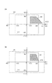
図3は取得部110が取得可能な2種類の画像サイズの画像データの表示範囲を表す図である。図3の例において、矩形枠300は画像サイズ1920×1080pixelの画像データ(第2の画像データ)の表示範囲を表している。また図3の例において、矩形枠310は画像サイズ1280×960pixelの画像データ(第1の画像データ)の表示範囲を表している。図3に示すように、矩形枠300は矩形枠310を包含する。図3の例では矩形枠300は、上述の設定範囲に対応する。
FIG. 3 is a diagram illustrating display ranges of image data of two types of image sizes that can be acquired by the
図3の例では、矩形枠300の中心と矩形枠310の中心が重なるようにして、それぞれの画像データの表示範囲を表している。ここで、図3の例における矩形枠300の中心は、矩形枠300の辺のうちX軸に平行な辺(縦の辺)の垂直二等分線と、Y軸に平行な辺(横の辺)の垂直二等分線との交点とすることができる。あるいは、矩形枠300の対角線の交点とすることができる。
In the example of FIG. 3, the display range of each image data is represented so that the center of the
図3に示した座標系では、矩形枠300の中心と矩形枠310の中心を重ねた点を座標系の原点としている。原点の位置は矩形枠300の中心に限られない。矩形枠300又は矩形枠310の頂点に座標系の原点を設定することとしてもよい。
In the coordinate system shown in FIG. 3, a point where the center of the
図3の例において、X軸は、取得部110が取得した画像データの縦方向の画素数を表している。また、図3の例においてY軸は、取得部110が取得した画像データの横方向の画素数を表している。
In the example of FIG. 3, the X axis represents the number of pixels in the vertical direction of the image data acquired by the
図3の斜線部分は、矩形枠300と矩形枠310が重ならない領域を表している。すなわち斜線部分は、取得する画像データを、より画像サイズが大きい1920×1080pixelの画像データから、より画像サイズが小さい1280×960pixelの画像データに切り替えた場合に、表示装置に表示されなくなる表示範囲を示している。なお矩形枠300及び310を用いて示した画像サイズは一例であり、この限りではない。
The hatched portion in FIG. 3 represents a region where the
矩形枠300の左右の部分だけ矩形枠310と重ならないようにしてもよい。例えば、矩形枠300が示す画像の画像サイズを1920×1080pixel(アスペクト比16:9)とし、矩形枠310が示す画像の画像サイズを1440×1080pixel(アスペクト比4:3)としてもよい。同様に、矩形枠300の上下の部分だけ矩形枠310と重ならないようにしてもよい。
The left and right portions of the
設定部130は、取得部110が取得可能な画像サイズが異なる複数の画像データのうち、より画像サイズが大きい画像データの表示範囲内(図3の例では矩形300の範囲内)に、解析図形を設定することができる。解析図形には、例えば、画像データにおいて解析処理を行う範囲を示す解析領域を示す図形や、通過検知処理を行うために用いる検知領域を示す図形などが含まれる。
The
すなわち、図3の斜線部分に解析領域又は検知線の一部または全体が重複するようにして、解析領域又は検知線を設定することができる。解析領域の設定の例については、図4を用いて後述する。 That is, the analysis region or the detection line can be set so that a part or the whole of the analysis region or the detection line overlaps with the hatched portion in FIG. An example of setting the analysis area will be described later with reference to FIG.
記憶部140は、設定部130が設定した解析領域の設定値を記憶する。例えば、記憶部140は、撮像装置の撮像可能範囲における解析図形の各頂点の位置を示す位置情報を記憶する。また例えば記憶部140は、表示装置に表示させる撮像画像の表示範囲であって解析図形を含む第2の表示範囲における、解析図形の各頂点の位置を示す位置情報を記憶する。本実施例では、解析図形の頂点として検知線の端点を含むものとする。例えば、記憶部140は、2つの端点の指定によって規定される線、又は、2つの端点の指定によって規定される線が複数つなげられた線である第1の線の各端点の、撮像可能範囲における位置を示す位置情報を記憶する。また例えば、第1の線を含む第2の画像データの表示範囲における、第1の線の各端点の位置を示す位置情報を記憶する。
The
また記憶部140は、後述の制御部150がCPU(Central Processing Unit)等のプロセッサを内蔵する場合には、当該プロセッサに実行させるためのプログラムを記録する。また記憶部140は、解析部120や制御部150が処理を行うために用いる作業領域として用いられる。記憶部140は例えば、RAM(Random Access Memory)やROM(Read Only Memory)等により構成することができる。記憶部140として、メモリカード等のリムーバブルメディアを用いることとしてもよい。また記憶部140は、その一部又は全体が外部記憶装置により構成されてもよい。記憶部140は、複数の記録媒体により構成することができる。
In addition, when the
制御部150は、図1に示した解析装置100の各構成の動作を制御する。制御部150は例えば、CPU等のプロセッサにより構成することができる。制御部150がプロセッサとして構成される場合、制御部150は記憶部140に記憶されたプログラムを読み出して実行することにより、図1に示した解析装置100の各構成の動作を制御する。
The
インタフェース部160(以下、I/F部160)は、解析部120の解析結果を出力する。またI/F部160は、設定部130に設定値を入力する。例えばI/F部160は信号入出力端子として構成される。I/F部160は、例えば、キーボード、タッチパネル、又はマウス等の入力機器から信号の入力を受けることができる。また、I/F部160は、解析部120の解析結果を表示装置等に出力することができる。またI/F部160は、取得部110とEthernet(登録商標)を共用して、外部の入出力端末と通信する構成にしてもよい。
The interface unit 160 (hereinafter referred to as I / F unit 160) outputs the analysis result of the
例えば、解析装置100はネットワークカメラの撮像部が撮像した撮像画像に対して画像解析を行うカメラサーバである。撮像部が撮像した撮像画像は取得部110から入力される。解析装置100は後述する画像解析処理を行った後、解析結果をネットワークを介してクライアント装置に出力する。解析結果はI/F部160から、ネットワークを介してクライアント装置に出力される。またI/F部160は、クライアント装置から解析処理を行うための設定命令を受信する。例えばI/F部160は、クライアント装置の表示画面上においてユーザが指定した解析図形の設定情報(例えば、取得部110が入力した撮像画像における解析図形の座標等)を受信する。制御部150は受信した設定情報を解析部120に対して設定する。解析部120は制御部150によって設定された設定値に基づいて、後述する画像解析処理を行う。
For example, the
或いは、解析装置100は、ネットワークカメラからネットワークを介して受信した撮像画像に対して画像解析を行うクライアント装置である。ネットワークカメラから受信した撮像画像は、取得部110からクライアント装置に入力される。解析装置100は後述する画像解析処理を行った後、解析結果をクライアント装置の表示部に出力する。解析結果はI/F部160から、表示部に出力される。またI/F部160は、クライアント装置に接続されたマウスやキーボードなどの入力装置から解析処理を行うための設定命令を取得する。例えばI/F部160は、マウスやキーボードなどの入力装置を用いてユーザが指定した解析図形の設定情報を取得する。制御部150は受信した設定情報を解析部120に対して設定する。解析部120は制御部150によって設定された設定値に基づいて、後述する画像解析処理を行う。解析装置100と表示部は一体として構成されてもよい。
Alternatively, the
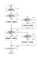
次に、本実施例に係る解析装置の動作について図2を用いて説明する。解析装置100の制御部150がプロセッサを内蔵する形態では、図2の処理フローは、図2に示す手順を制御部150に実行させるためのプログラムを示す。解析装置100の制御部150が内蔵するプロセッサはコンピュータであり、解析装置100が内蔵する記憶部140から読み出したプログラムを実行する。
Next, the operation of the analysis apparatus according to the present embodiment will be described with reference to FIG. In the form in which the
解析装置100が起動すると制御部150は、解析装置100に入力される画像データの画像サイズを取得部110を介して取得する制御を行う(S200)。取得部110は解析装置100に入力される画像データ(取得部110が取得する画像データ)の画像サイズが変更された際に、画像データの画像サイズを取得することとしてもよい。
When the
次に制御部150は、設定部130により設定され、記憶部140に記憶されている解析図形の設定値を記憶部140から読み出す(S210)。
Next, the
次に制御部150は、現在入力されている画像データの画像サイズと、ステップ210で取得した解析領域の設定値とを比較し、入力されている画像データの表示範囲外に解析図形の一部又は全体が設定されているか否かを判定する(S220)。いいかえると制御部150は、解析図形の全体が、入力されている画像データの表示範囲に含まれるか否かを判定する。
Next, the
ここで、入力されている画像データの表示範囲の範囲外に解析図形の一部又は全体が設定される場合について説明する。上述のように、設定部130は、取得部110が取得する複数の画像データの画像サイズのうち、より大きい画像サイズの範囲内で解析図形を設定することができる。例えば、図3に示した例では、設定部130は矩形枠300の範囲内で解析領域又は検知線を設定することができる。矩形枠310が示す画像サイズの画像データが解析装置100に入力されている場合、設定部130は、矩形枠300の範囲内であって、矩形枠310の範囲外である領域(図3の斜線部分)に解析領域、又は、検知線の一部又は全体を設定することができる。
Here, a case where a part or the whole of the analysis graphic is set outside the display range of the input image data will be described. As described above, the
制御部150は、図3を用いて説明した座標系と、入力されている画像データの画像サイズを示す矩形枠の座標系における領域と、座標系における解析図形の位置とに基づいて、ステップS220の判定を行うことができる。解析図形の位置には、例えば、解析領域の頂点座標や検知線の両端の座標等が含まれる。
The
入力されている画像データの画像サイズの範囲内に解析図形の全体が含まれている場合(S220でNoの場合)、制御部150は、ステップS210で読みだした設定値が示す解析図形を用いて、解析部120に解析処理を行わせる(S230)。すなわち、制御部150は、記憶部140に記憶されている設定値に基づく解析領域の範囲内で解析処理を行うように解析部120に指示する。あるいは制御部150は、記憶部140に記憶されている設定値に基づく検知線を用いて、通過検知を行うように解析部120に指示する。
When the entire analysis figure is included in the image size range of the input image data (No in S220), the
入力されている画像データの画像サイズの範囲外に解析図形の一部又は全体が設定されている場合(S220でYesの場合)、制御部150は、入力されている画像データの表示範囲に含まれるようにして解析図形を決定する(S240)。例えば、取得部110が現在取得している画像データの表示範囲と、設定部130によって設定された解析領域が重複する領域を示す図形を、解析部120に解析させる領域として決定する。また例えば、設定部130によって設定された第1の検知線のうち、取得部110が現在取得している画像データの表示範囲に含まれる部分を、解析部120が通過検知に用いる第2の検知線として決定する。解析部120に解析させる解析領域の決定方法については、図4を用いて説明する。
When a part or the whole of the analysis graphic is set outside the image size range of the input image data (Yes in S220), the
ステップS240において解析図形を決定すると、制御部150は、決定した解析図形を用いて解析処理を実行するように解析部120に指示する(S250)。例えば、制御部150は、ステップS240において決定した図形を解析処理を行う領域として決定し、解析部120に解析処理を指示する。または例えば、制御部150は、ステップS240において決定した検知線を、通過検知処理を行うための検知線に決定し、解析部120に解析処理を指示する。
When the analysis graphic is determined in step S240, the
ステップS230あるいはステップS250において解析処理が終了すると、制御部150は設定部130によって設定されている全ての解析処理が終了したか判定する(S260)。例えば、設定部130によって、複数の解析領域が設定されている場合、設定された全ての解析領域において解析処理が終了したか判定する。まだ解析処理が行われていない解析領域が存在する場合(ステップS260においてNoの場合)には、制御部150はステップS220の処理に戻る。全ての解析領域について解析処理が終了した場合には、制御部150は、処理を終了する。
When the analysis process ends in step S230 or step S250, the
次に、図2のステップS240における解析図形の決定処理について説明する。図2のステップS240における解析領域の決定処理について、図4(A)及び(B)を用いて説明する。図4(A)の例は、画像サイズ1920×1080pixelの画像データを示す矩形枠300の範囲内に、設定部130により解析図形400が設定された様子を表している。図4(A)の例では、画像サイズ1280×960pixelの画像データを示す矩形枠310の範囲の外に解析図形400の一部が設定されている。
Next, the analysis figure determination process in step S240 of FIG. 2 will be described. The analysis region determination process in step S240 of FIG. 2 will be described with reference to FIGS. The example of FIG. 4A shows a state in which the analysis figure 400 is set by the
解析装置100がネットワークカメラに含まれる場合、図4(A)及び(B)はネットワークカメラにネットワークを介して接続されたクライアント装置の表示部に表示される設定画面を表す
ただし、図4(A)において点線で示した矩形枠310は、設定画面に表示しないこととしてもよい。また、図4(B)において点線で示した矩形枠300は設定画面に表示しないこととしてもよい。
When the
解析装置100は、解析図形の設定可能範囲を示す矩形枠300における解析図形400の設定位置を示す設定情報(例えば、解析図形の頂点座標)をクライアント装置から受信する。例えば、解析装置100は図4(A)に示した解析図形400の頂点座標を受信する。例えばクライアントの指示により撮像画像の表示範囲が変更された場合、解析装置100の設定部130は受信した設定情報を用いて解析図形を新たに設定する。解析装置100は新たに設定した解析図形の矩形枠300における位置を示す情報をクライアント装置に送信する。クライアント装置は解析装置100が新たに設定した解析図形を表示部に表示する。このとき表示部に表示される、新たに設定された解析図形410の例を図4(B)に示す。
The
制御部150は、例えば、解析図形400を構成する各頂点の座標値が矩形枠310の各辺を越えるかどうかにより、解析図形400の一部が矩形枠310の範囲外に設定されているか否かを判定することができる。
For example, the
例えば、図4(A)に示した解析図形400の頂点400Dの水平座標値(x軸座標)は840であり、これは矩形枠310の右辺の水平座標値である640を越えているので、矩形枠310の範囲外に解析領域の一部が存在すると判定することができる。
For example, the horizontal coordinate value (x-axis coordinate) of the
同様に、解析図形400の頂点400A、400Bについても、各頂点の垂直座標値(y軸座標)を、矩形枠310の垂直座標値を比較することにより、矩形枠310の範囲外に解析領域の一部が存在すると判定することができる。
Similarly, with respect to the
取得部110が現在取得している画像データの画像サイズが矩形枠310に応じた大きさである場合、制御部150は、図4(B)に示すように矩形枠310の範囲内に解析領域が含まれるように解析領域を決定する。すなわち制御部150は、解析図形400の各辺と矩形枠310の交点を求め、求めた交点と、解析図形400の頂点のうち矩形枠310の範囲内にある頂点とを結んだ領域を、解析部120に解析処理を行わせる解析図形410とする。図4(B)の例では、矩形枠310との交点400a、400b、400c、400d、400eと、矩形枠310の範囲内にある頂点400cとで囲まれた範囲が解析図形410となる。
When the image size of the image data currently acquired by the
このようにして、解析部120に解析処理を行わせる解析図形410が決定されると、制御部150は、新たな解析図形410の領域内の画像データについて、解析処理を行うように解析部120に指示する(S250)。
In this way, when the analysis figure 410 that causes the
解析図形として検知線を決定する場合も同様にして、矩形枠310の範囲内に含まれるように検知線を決定し、決定した検知線を用いて解析部120に通過検知処理を行わせることができる。
Similarly, when a detection line is determined as an analysis figure, the detection line is determined so as to be included within the range of the
本実施例では、設定部130は、取得部110が取得可能な画像サイズが異なる複数の画像データのうち、より画像サイズが大きい画像データの表示範囲内(図3の例では矩形枠300の範囲内)に解析図形を設定することができる。そして、設定された解析図形を示す情報が記憶部140に記憶される。
In the present embodiment, the
本実施例では、図2を用いて説明したステップS200からステップS260までの処理を実行する間、記憶部140が記憶する解析図形の設定内容は変更されない。すなわち、記憶部140に記憶される解析図形を示す情報は、より画像サイズが大きい画像データの表示範囲内において設定部130が設定した内容のまま保持される。
In the present embodiment, while the processing from step S200 to step S260 described with reference to FIG. 2 is executed, the setting content of the analysis graphic stored in the
記憶部140から読み出した解析図形が解析装置100に入力されている画像データの表示範囲からはみ出す場合、制御部150は、入力されている画像データの範囲内に解析図形が含まれるように解析図形を修正し、解析部120に解析処理を実行させる。
When the analysis graphic read out from the
このようにして、設定部130によって設定された解析領域の一部又は全体が、解析装置100に入力されている画像データの表示範囲の外に設定されている場合であっても、ユーザが解析領域の設定を変更することなく、解析処理を実行することができる。
In this way, even if a part or the whole of the analysis region set by the
図4の例では、物体検知処理を行うための検知領域の設定について説明したが、通過検知処理を行うための検知線についても同様にして、解析図形(検知線)の変更を行うことができる。例えば、図4に示す枠300において、2つの端点の指定によって規定される線が複数つなげられた第1の線が設定された場合にも適用することができる。
In the example of FIG. 4, the setting of the detection area for performing the object detection process has been described. However, the analysis figure (detection line) can be similarly changed for the detection line for performing the passage detection process. . For example, in the
検知線の決定の例について図8(A)及び(B)を用いて説明する。図8は図4と同様に、クライアント装置の表示部に表示される設定画面の例である。図8(A)は表示範囲が枠300の範囲である場合に設定される検知線を示している。また図8(B)は表示範囲が枠310の範囲である場合に設定される検知線を示している。図8(A)において点線で示した矩形枠310は、設定画面に表示しないこととしてもよい。また、図8(B)において点線で示した矩形枠300は設定画面に表示しないこととしてもよい。
An example of detection line determination will be described with reference to FIGS. FIG. 8 is an example of a setting screen displayed on the display unit of the client device, as in FIG. FIG. 8A shows detection lines that are set when the display range is within the range of the
図8(A)において、2つの端点の指定によって規定される線803及び線804は、つなげられて第1の線を構成する。線803は矩形枠310の辺と第1の点801で交差する。また、線804は矩形枠310の辺と第2の点802で交差する。表示範囲が枠300から枠310に変更されると、設定部は、第1の点801と、第2の点802と、第1の線を規定する端点のうち矩形枠310の範囲内に設定された端点とにより規定される第2の線を決定する。そして、図8(B)に示した当該第2の線を、通過検知処理を行うための検知線に決定することができる。
In FIG. 8A, a
また、第1の画像サイズの範囲内で第1の解析図形が設定され、次に、画像サイズが第1の画像サイズよりも小さい第2の画像サイズに変更され、そして、画像サイズが第1の画像サイズに戻された場合に、第1の解析図形を再設定することができる。すなわち、画像サイズが第1の画像サイズから第2の画像サイズに変更されたことに応じて解析図形を第1の解析図形から第2の解析図形に変更した場合でも、画像サイズが第1の画像サイズに戻った場合には、第1の解析図形を再設定することができる。 In addition, the first analysis graphic is set within the range of the first image size, the image size is then changed to a second image size smaller than the first image size, and the image size is changed to the first image size. When the image size is restored, the first analysis figure can be reset. That is, even when the analysis graphic is changed from the first analysis graphic to the second analysis graphic in response to the image size being changed from the first image size to the second image size, the image size is the first image size. When returning to the image size, the first analysis figure can be reset.
図4に示した例を用いて、解析処理を行うために用いる第1の解析図形400が画像処理装置に設定され、第1の解析図形400を特定するための位置情報が記憶部140に記憶されている場合について説明する。画像データの表示範囲は図4(B)に示した枠310の範囲であり、画像解析を行うために用いる図形として解析図形410が用いられているものとする。画像データの表示範囲を第1の解析図形400の頂点のうち少なくとも1つの頂点を含まない第1の表示範囲(枠310)から、第1の解析図形400を含む第2の表示範囲(枠300)に変更した場合、第1の解析図形400を解析図形に決定する。解析図形の決定は、記憶部140に記憶された位置情報に基づいて行われる。
Using the example shown in FIG. 4, the first analysis graphic 400 used for performing the analysis processing is set in the image processing apparatus, and the positional information for specifying the first analysis graphic 400 is stored in the
このようすれば、第1の表示範囲(枠310)が表示されている間は、第1の表示範囲に含まれる第2の解析図形410を用いて解析処理を行い、表示範囲が第2の表示範囲300に切り替わると、第1の解析図形400を用いて解析処理を行うことができる。このようにして、ユーザが解析領域の設定を変更することなく解析処理を実行することができる。
In this way, while the first display range (frame 310) is displayed, analysis processing is performed using the second analysis graphic 410 included in the first display range, and the display range is the second display range. When the
このように本実施例によれば、複数の異なる画像サイズの画像データの解析処理を行う解析装置100に対して、ユーザは簡便な方法で、解析部120に解析処理を行わせるために用いる解析図形を設定することができる。
As described above, according to this embodiment, the
解析図形として用いる検知線は、多角形として閉じていない折れ線としてもよい。また解析図形の座標値の設定に制約がある場合、制約にあうように設定値を修正してもよい。例えば、1画素単位ではなく8画素単位でなければ解析図形の頂点座標を設定できない場合等で、撮像範囲矩形枠との交点の座標値が8画素単位にならない場合は、交点の座標の値を四捨五入する等して、設定制約に合致するようにすることができる。 The detection line used as the analysis figure may be a polygonal line that is not closed as a polygon. If there is a restriction on the setting of the coordinate value of the analysis figure, the setting value may be corrected so as to meet the restriction. For example, if the vertex coordinate of the analysis figure cannot be set unless it is 8 pixel units instead of 1 pixel unit, and the coordinate value of the intersection point with the imaging range rectangular frame is not 8 pixel units, the coordinate value of the intersection point is set to It can be rounded off to meet the setting constraints.
(実施例2)
第2の実施例では、設定可能な解析図形の頂点数に上限がある場合の解析処理について説明する。解析図形の頂点数とは、例えば、解析図形が上述の解析領域である場合には、解析領域の頂点の数である。また本実施例において、解析図形の頂点数には、解析図形が上述の検知線である場合には、2つの端点の指定によって規定される線、又は、2つの端点の指定によって規定される線が複数つなげられた線を規定する端点の数を含む。
(Example 2)
In the second embodiment, an analysis process when there is an upper limit to the number of vertices of an analysis figure that can be set will be described. The number of vertices of the analysis figure is, for example, the number of vertices in the analysis area when the analysis figure is the analysis area described above. Further, in this embodiment, the number of vertices of the analysis figure is a line defined by designation of two end points or a line defined by designation of two end points when the analysis figure is the detection line described above. Contains the number of endpoints that define the connected lines.
例えば、設定可能な解析図形の頂点数に上限がある場合の例として、設定可能な解析図形の頂点数の上限が4つである場合について説明する。 For example, as an example of the case where there is an upper limit on the number of vertices of an analysis figure that can be set, a case where the upper limit of the number of vertices of an analysis figure that can be set is four will be described.
図4(A)の例では、記憶部140に記憶されている解析図形400の頂点数は4つである。しかし、制御部150が新たな解析領域を決定した後の解析図形410の頂点数は、図4(B)に示したように、5に増える。このような場合、制御部150が決定した解析領域の頂点の数が、設定可能な解析図形の頂点数の上限を超えてしまうこととなる。
In the example of FIG. 4A, the number of vertices of the analysis figure 400 stored in the
本実施例では、このように制御部150が解析領域を決定した後の解析図形の頂点の数が、解析図形の頂点数の上限値を超えないようにして解析処理を行う例について説明する。
In the present embodiment, an example will be described in which analysis processing is performed such that the number of vertices of the analysis figure after the
本実施例に係る解析装置100の構成は、実施例1において図1を用いて説明した構成と同じであるため、説明を省略する。
The configuration of the
本実施例に係る解析処理の動作は、実施例1において図2を用いて説明した一連の処理のうち、ステップS240における解析図形の決定処理の方法が異なる。その他の処理については実施例1において図2を用いて説明した内容と同じであるため、説明を省略する。 The operation of the analysis processing according to the present embodiment differs from the series of processing described in Embodiment 1 with reference to FIG. The other processes are the same as those described in the first embodiment with reference to FIG.
本実施例における解析図形の決定処理(図2のステップS240)について、図5を用いて説明する。本実施例では、設定範囲300上に設定された解析図形の頂点のうち1つの頂点が画像データの表示範囲を示す矩形枠310の範囲外に設定され、解析図形の他の頂点が矩形枠310表示範囲の範囲内に設定されている場合ついて説明する。
The analysis figure determination process (step S240 in FIG. 2) in the present embodiment will be described with reference to FIG. In the present embodiment, one of the vertices of the analysis figure set on the
解析装置100の制御部150がプロセッサを内蔵する形態では、図5の処理フローは、図5に示す手順を制御部150に実行させるためのプログラムを示す。解析装置100の制御部150が内蔵するプロセッサはコンピュータであり、解析装置100が内蔵する記憶部140から読み出したプログラムを実行する。
In the form in which the
まず制御部150は、実施例1で上述した設定範囲内で設定部130が設定した解析図形の頂点のうち1つの頂点の座標を取得する(S500)。
First, the
次に制御部150は、現在の撮像画像の表示範囲の範囲外に解析図形の頂点が設定されているか判定する。図5に示した例では、制御部150はステップS500で取得した頂点の位置が、表示範囲を示す矩形枠の右端を超えるか判定する(S510)。
Next, the
取得した頂点の位置が、表示範囲を示す矩形枠の右端を超える場合(S510でYesの場合)、表示範囲を示す矩形枠310の水平座標の範囲内となるように当該頂点の水平座標を変更する(S520)。図5に示した例では、ステップS500で取得した頂点の水平座標が、表示範囲を示す矩形枠310の右端の水平座標と等しくなるように変更する。頂点の水平座標を右端の水平座標と等しくする場合に限らず、頂点の水平座標が表示範囲の範囲内となるように変更されればよい。
If the acquired vertex position exceeds the right edge of the rectangular frame indicating the display range (Yes in S510), the horizontal coordinate of the vertex is changed to be within the horizontal coordinate range of the
図6(A)は、画像サイズ1920×1080pixelの画像データ(第2の画像データ)の表示範囲を示す矩形枠300において設定された解析図形600の頂点のうち1つの頂点が矩形枠300の範囲外に設定された様子を示している。図6(A)に示した例において、解析図形600の他の頂点は矩形枠300の範囲内に設定されている。ここで、矩形枠300は、撮像装置が撮像可能な撮像範囲を示す枠としてもよい。
FIG. 6A shows a range in which one vertex of the vertices of the analysis figure 600 set in the
解析装置100がネットワークカメラに含まれる場合、図6(A)及び(B)はネットワークカメラにネットワークを介して接続されたクライアント装置の表示部に表示される設定画面を表す。
When the
ただし、図6(A)において点線で示した矩形枠310は、設定画面に表示しないこととしてもよい。また、図6(B)において点線で示した矩形枠300は設定画面に表示しないこととしてもよい。
However, the
図6(A)を用いてステップS500において頂点600Dの座標を取得した場合について説明する。制御部150は、頂点600Dの水平座標(X=840)が、表示範囲を示す矩形枠310の右端の水平座標(X=640)をX方向に超えているか判定する(S510)。図6(A)の例では、頂点600Dが表示範囲の右端を超えているため、表示範囲を示す矩形枠310の水平座標の範囲内(−640≦X≦640)となるように、頂点600Dの水平座標を変更する。例えば、頂点600Dの水平座標をX=640とする。
A case where the coordinates of the
ステップS500において取得した頂点の位置が、表示範囲の右端を超えない場合(S510でNoの場合)、ステップS500において取得した頂点の位置が表示範囲の左端を超えているか判断する(S530)。 If the vertex position acquired in step S500 does not exceed the right end of the display range (No in S510), it is determined whether the vertex position acquired in step S500 exceeds the left end of the display range (S530).
ステップS500において取得した頂点の位置が表示範囲の左端を超えている場合(S530でYesの場合)、表示範囲を示す矩形枠の範囲内となるように当該頂点の水平座標を変更する(S540)。図5に示した例では、ステップS500で取得した頂点の水平座標が、表示範囲を示す矩形枠の左の水平座標と等しくなるように変更する。頂点の水平座標を左端の水平座標と等しくする場合に限らず、頂点の水平座標が表示範囲の範囲内となるように変更されればよい。 When the position of the vertex acquired in step S500 exceeds the left end of the display range (Yes in S530), the horizontal coordinate of the vertex is changed so as to be within the rectangular frame indicating the display range (S540). . In the example illustrated in FIG. 5, the horizontal coordinate of the vertex acquired in step S500 is changed to be equal to the horizontal coordinate on the left of the rectangular frame indicating the display range. The horizontal coordinate of the vertex is not limited to be equal to the horizontal coordinate of the left end, and may be changed so that the horizontal coordinate of the vertex is within the display range.
ステップS500で取得した頂点の水平座標が表示範囲を示す枠の範囲内である場合(S530でNoの場合)、ステップS520の処理を行った場合、又は、ステップS540の処理を行った場合には、制御部150はステップS550の処理を行う。
When the horizontal coordinate of the vertex acquired in step S500 is within the range of the frame indicating the display range (in the case of No in S530), when the process of step S520 is performed, or when the process of step S540 is performed The
ステップS550では、制御部150は、ステップS500で取得した頂点の位置が表示範囲を示す矩形枠の上端を超えるか判定する。取得した頂点の位置が、表示範囲を示す矩形枠の上端を超える場合(S550でYesの場合)、表示範囲を示す矩形枠の垂直座標の範囲内となるように当該頂点の垂直座標を変更する(S560)。図5に示した例では、ステップS500で取得した頂点の垂直座標が、表示範囲を示す矩形枠の上端の垂直座標と等しくなるように変更する。頂点の垂直座標を上端の垂直座標と等しくする場合に限らず、頂点の垂直座標が表示範囲の範囲内となるように変更されればよい。
In step S550, the
ステップS550において取得した頂点の位置が、表示範囲の上端を超えない場合(S550でNoの場合)、ステップS500において取得した頂点の位置が表示範囲の下端を超えているか判断する(S570)。 If the vertex position acquired in step S550 does not exceed the upper end of the display range (No in S550), it is determined whether the vertex position acquired in step S500 exceeds the lower end of the display range (S570).
ステップS500において取得した頂点の位置が表示範囲の下端を超えている場合(S570でYesの場合)、表示範囲を示す矩形枠の範囲内となるように当該頂点の垂直座標を変更する(S580)。図5に示した例では、ステップS500で取得した頂点の垂直座標が、表示範囲を示す矩形枠の左の垂直座標と等しくなるように変更する。頂点の垂直座標を下端の垂直座標と等しくする場合に限らず、頂点の垂直座標が表示範囲の範囲内となるように変更されればよい。 When the position of the vertex acquired in step S500 exceeds the lower end of the display range (Yes in S570), the vertical coordinates of the vertex are changed so as to be within the rectangular frame indicating the display range (S580). . In the example shown in FIG. 5, the vertical coordinate of the vertex acquired in step S500 is changed to be equal to the left vertical coordinate of the rectangular frame indicating the display range. The vertical coordinate of the vertex is not limited to be equal to the vertical coordinate of the lower end, but may be changed so that the vertical coordinate of the vertex is within the display range.
ステップS500において取得した頂点の位置が表示範囲の下端を超えていないと判定された場合(S570でNoの場合)、ステップS580の処理を行った場合、ステップS560の処理を行った場合には、制御部150はステップS590の処理を行う。
When it is determined that the position of the vertex acquired in step S500 does not exceed the lower end of the display range (No in S570), when the process of step S580 is performed, when the process of step S560 is performed, The
ステップS590において、制御部150は、解析図形の全ての頂点についてステップS510からステップS590までの処理を行ったか判定する。処理を行っていない頂点が存在する場合には、制御部150はステップS500に戻り、当該処理を行っていない頂点についてステップS500から始まる処理を繰り返す。
In step S590, the
ステップS590において、解析図形の全ての頂点について処理を行ったと判定した場合には、制御部150は処理を終了する。
If it is determined in step S590 that processing has been performed for all vertices of the analysis figure, the
図6(A)に示した斜線部分に解析図形600が指定された場合に、図5に示した処理を終了した後、再設定される解析図形600を図6(B)に示す。図6(B)に示す解析図形は、表示範囲を示す矩形枠310の範囲外に設定された頂点を、矩形枠310の範囲内に移動させた頂点と矩形枠310の範囲内に設定された他の頂点とにより規定される。
FIG. 6B shows the analysis figure 600 that is reset after the process shown in FIG. 5 is completed when the analysis figure 600 is designated in the hatched portion shown in FIG. In the analysis figure shown in FIG. 6B, the vertex set outside the
図6(A)の例では、4つの頂点によって規定される図形を解析図形600とする場合について説明したが、解析図形600は2つの端点の指定によって規定される線、又は、2つの端点の指定によって規定される線が複数つなげられた線としてもよい。そして、当該線(第1の線)を規定する端点が矩形枠310の範囲内にあるか否かの判定を、図5に示した処理に従って実行することとしてもよい。
In the example of FIG. 6A, the case where the figure defined by the four vertices is the analysis figure 600 has been described, but the analysis figure 600 is a line defined by the designation of two end points, or two end points. It may be a line in which a plurality of lines defined by designation are connected. And it is good also as determining whether the end point which prescribes | regulates the said line (1st line) exists in the range of the
検知線の決定の例について図9(A)及び(B)を用いて説明する。図9は図6と同様に、クライアント装置の表示部に表示される設定画面の例である。図9(A)において点線で示した矩形枠310は、設定画面に表示しないこととしてもよい。また、図9(B)において点線で示した矩形枠300は設定画面に表示しないこととしてもよい。
An example of detection line determination will be described with reference to FIGS. FIG. 9 is an example of a setting screen displayed on the display unit of the client device, as in FIG. The
枠300の範囲において指定された第1の線の各端点のうち1つの端点904が矩形枠310の範囲外に設定され、第1の線の他の端点が矩形枠310の範囲内に設定された場合について説明する。図9(A)に示した第1の線は、線901、線902、線903を含む。表示範囲を枠300から枠310に変更した場合に設定される検知線の例を図9(B)に示す。矩形枠310の範囲外に設定された端点904を矩形枠310の範囲内に移動させた端点907と矩形枠310の範囲内に設定された端点とによって規定される第2の線を、通過検知処理を行うための検知線に決定する。第2の線は、線905、先駆906、線903を含む。
Of the end points of the first line designated within the range of the
このようにして、解析図形600の頂点数と解析図形600の頂点数とが同じになるようにしつつ、表示範囲を示す矩形枠310の範囲内に解析図形600を設定することができる。すなわち、頂点の数が図6(A)に示す第1の解析図形600の頂点の数以下となる、矩形枠300に含まれる図6(B)に示す第2の解析図形を、解析処理を行う領域又は検知線に決定することができる
図5に示した例では、解析図形の頂点が撮像範囲を超えるか否かの判定を、撮像範囲の右端、左端、上端、下端の順に行う場合について説明したが、これらの判定の順序は、図5に示した順序に限られず、変更することが可能である。
In this way, the analysis figure 600 can be set within the range of the
次に、解析図形が表示範囲の外側に設定された場合について、図7(A)及び(B)を用いて説明する。図7(A)は表示範囲を示す矩形枠310の外側に解析図形700が設定された様子を示している。このとき、図5を用いて説明した一連の処理を実行した結果を図7(B)に示す。
Next, the case where the analysis figure is set outside the display range will be described with reference to FIGS. FIG. 7A shows a state in which the analysis figure 700 is set outside the
解析装置100がネットワークカメラに含まれる場合、図7(A)及び(B)はネットワークカメラにネットワークを介して接続されたクライアント装置の表示部に表示される設定画面を表す。
When the
ただし、図7(A)において点線で示した矩形枠310は、設定画面に表示しないこととしてもよい。また、図7(B)において点線で示した矩形枠300は設定画面に表示しないこととしてもよい。
However, the
図7(B)において頂点700aから700fは、それぞれ、図7(A)の700Aから700Fを置換した頂点である。図7(B)において、頂点700aと頂点700bは同一の座標値を有する。また、頂点700eと頂点700fは同一の座標値を有する。このように、解析領域の全体が表示範囲の範囲外に設定されている場合に、表示範囲の枠線上に、解析図形の存在を示す線を表示させることができる。
In FIG. 7B,
このようにして、検知処理を行う範囲を決定するために用いる第1の図形の全体が表示範囲を示す枠310の範囲外に設定された場合、第1の図形の全体が矩形枠310の範囲外に設定されていることを示す第2の図形を矩形枠310の辺上に表示させる。
In this way, when the entire first graphic used to determine the detection processing range is set outside the
あるいは、撮像画像を撮像する撮像手段の撮像可能範囲において2つの端点の指定によって規定される線、又は、2つの端点の指定によって規定される線が複数つなげられた線の全体が矩形枠310の範囲外に設定された場合、同様の処理を行うことができる。すなわち第1の図形の全体が矩形枠310の範囲外に設定されていることを示す図形を、矩形枠310の辺上に表示させる。
Alternatively, the whole of the line defined by the designation of the two end points in the imaging range of the imaging unit that captures the captured image or a plurality of lines defined by the designation of the two end points is the
これらの表示制御処理は、図1に示した制御部150が、I/F部160を介して、表示装置に対して行うことができる。
These display control processes can be performed on the display device by the
このようにすれば、表示範囲枠外に解析領域が設定されていることをユーザに視覚的に示すことができる。表示範囲の枠線上に解析図形の存在を示す線を引く場合に限らず、移動後の各頂点を示す点のみを表示することとしてもよい。 In this way, it is possible to visually indicate to the user that the analysis area is set outside the display range frame. Not only when a line indicating the presence of an analysis figure is drawn on the frame line of the display range, but only the points indicating each vertex after movement may be displayed.
なお本実施例と第1の実施例の動作は排他的なものではなく、組み合わせてもよい。例えば、矩形枠310と図6(A)に示す解析図形600とが重複する領域の頂点数が設定可能な頂点数を超えない場合、当該重複した領域を示す図形(第3の図形)を、解析処理を行う領域に決定する。この第3の図形は、図6(A)における解析図形600の各辺と矩形枠310の交点と、解析図形600の頂点のうち矩形枠310の範囲内にある頂点とを結んだ領域を示す図形である。このようにして、第3の図形の頂点の数が所定の数以下である場合には、第3の図形を解析処理を行う領域に決定する。
The operations of the present embodiment and the first embodiment are not exclusive and may be combined. For example, when the number of vertices in the area where the
一方、第3の図形の頂点数が、解析装置100が設定可能な解析図形の頂点数を超える場合、解析図形の頂点数が変わらないようにして、解析図形の大きさを変更する。すなわち、変更後の解析図形は図6(B)示したようになる。このようにして、第3の図形の頂点の数が所定の数よりも多い場合には、図6(B)に示した解析図形600を解析処理を行う領域に決定する。
On the other hand, when the number of vertices of the third figure exceeds the number of vertices of the analysis figure that can be set by the
または、解析領域のうち表示範囲を示す矩形枠310からはみ出す領域を切り取った解析図形を設定すると、再設定後の解析図形の頂点数が、解析装置100が設定可能な解析図形の頂点数を超える場合、頂点ごとに変更後の座標の決定方法を異ならせてもよい。すなわち、設定された解析図形の頂点のうち、一部の頂点は実施例1に示した方法で変更後の位置を決定し、残りの頂点は実施例2に示した方法で変更後の位置を決定してもよい。このとき、いずれの頂点の位置をいずれの方法によって変更するかは、例えば、はみ出した頂点と表示範囲を示す矩形枠310との距離に応じて決定することができる。例えば、変更前の解析図形の頂点のうち、矩形枠310から距離が遠い頂点から、実施例2に示した方法で頂点位置を変更することとしてもよい。
Alternatively, when an analysis figure obtained by cutting out an area protruding from the
また、実施例1と同様に、第1の解析図形の頂点のうち少なくとも1つの頂点を含まない第1の表示範囲から、第1の解析図形を含む第2の表示範囲に変更した場合、記憶部140に記憶された位置情報に基づいて第1の解析図形を解析領域に決定できる。このようすれば、第1の表示範囲が表示されている間は、第1の表示範囲に含まれる第2の解析図形を用いて解析処理を行い、表示範囲が第2の表示範囲に切り替わると、第1の解析図形を用いて解析処理を行うことができる。このようにして、ユーザが解析領域の設定を変更することなく解析処理を実行することができる。
Similarly to the first embodiment, when the first display range that does not include at least one vertex among the vertices of the first analysis graphic is changed to the second display range that includes the first analysis graphic, the memory is stored. Based on the position information stored in the
本発明はこれらの実施形態に限定されず、その要旨の範囲内で種々の変形および変更が可能である。 The present invention is not limited to these embodiments, and various modifications and changes can be made within the scope of the gist.
(その他の実施例)
また、本発明は、以下の処理を実行することによっても実現される。即ち、上述した実施形態の機能を実現するソフトウェア(プログラム)を、ネットワーク又は各種記憶媒体を介してシステム或いは装置に供給し、そのシステム或いは装置のコンピュータ(またはCPUやMPU等)がプログラムを読み出して実行する処理である。
(Other examples)
The present invention can also be realized by executing the following processing. That is, software (program) that realizes the functions of the above-described embodiments is supplied to a system or apparatus via a network or various storage media, and a computer (or CPU, MPU, or the like) of the system or apparatus reads the program. It is a process to be executed.
100 解析装置
110 入力部
120 解析部
130 設定部
140 記憶部
150 制御部
160 I/F部
DESCRIPTION OF
Claims (16)
所定の検知領域又は検知線に基づいて、前記取得手段によって取得される撮像画像に対する解析処理を行う解析手段と、
前記取得手段によって取得される撮像画像に対応する範囲が第1の範囲から第2の範囲に変更されると、前記取得手段によって取得される撮像画像に対応する範囲が変更される前における前記検知領域又は前記検知線に基づいて、前記取得手段によって取得される撮像画像に対応する範囲が変更された後における前記検知領域又は前記検知線を決定する決定手段と
を有し、
前記決定手段は、
前記取得手段によって取得される撮像画像に対応する範囲が前記第1の範囲から前記第2の範囲に変更されると、前記取得手段によって取得される撮像画像に対応する範囲が変更される前における前記検知領域の頂点のうちの所定の頂点が前記第2の範囲外となり、他の頂点が前記第2の範囲内となると判断した場合、
前記取得手段によって取得される撮像画像に対応する範囲が変更された後における前記検知領域の頂点の数が、前記取得手段によって取得される撮像画像に対応する範囲が変更される前における前記検知領域の頂点の数以下となるように、前記検知領域を決定する
をことを特徴とする画像処理装置。 Acquisition means for acquiring a captured image captured by the imaging means;
Analysis means for performing analysis processing on a captured image acquired by the acquisition means based on a predetermined detection region or detection line;
When the range corresponding to the captured image acquired by the acquisition unit is changed from the first range to the second range, the detection before the range corresponding to the captured image acquired by the acquisition unit is changed. region or on the basis of the detection line, have a determining means for determining the detection area or the sensing wire in after being changed range corresponding to the captured image acquired by the acquisition means,
The determining means includes
When the range corresponding to the captured image acquired by the acquisition unit is changed from the first range to the second range, the range corresponding to the captured image acquired by the acquisition unit is changed. When it is determined that a predetermined vertex of the detection region vertices is outside the second range and the other vertices are within the second range,
The number of vertices of the detection region after the range corresponding to the captured image acquired by the acquisition unit is changed, the detection region before the range corresponding to the captured image acquired by the acquisition unit is changed The detection area is determined so that the number of vertices is less than or equal to
An image processing apparatus characterized by the above.
前記取得手段によって取得される撮像画像に対応する範囲が前記第1の範囲から前記第2の範囲に変更されると、前記取得手段によって取得される撮像画像に対応する範囲が変更される前における検知線の端点のうち所定の端点が前記第2の範囲の範囲外となり、他の端点が前記第2の範囲の範囲内となると判断した場合、
前記所定の端点を前記第2の範囲の範囲内に移動させた端点と前記他の端点とによって規定される線を、前記取得手段によって取得される撮像画像に対応する範囲が変更された後における前記検知線の少なくとも一部として決定する
をことを特徴とする請求項1に記載の画像処理装置。 The determining means includes
When the range corresponding to the captured image acquired by the acquisition unit is changed from the first range to the second range, the range corresponding to the captured image acquired by the acquisition unit is changed. When it is determined that a predetermined end point of the detection line is outside the range of the second range and the other end point is within the range of the second range,
After the range corresponding to the captured image acquired by the acquisition unit is changed, the line defined by the end point obtained by moving the predetermined end point within the range of the second range and the other end point is changed. The image processing apparatus according to claim 1, wherein the image processing apparatus is determined as at least a part of the detection line.
前記取得手段によって取得される撮像画像に対応する範囲が変更される前における前記検知線が、複数の線を繋げた線である場合であって、前記複数の線のうちの第1の線の端点と第2の線の端点とが前記第2の範囲外となると判断した場合、
前記第1の線と前記第2の範囲の端部との交点と、
前記第2の線と前記第2の範囲の端部との交点と、
前記複数の線の端点のうちの、前記取得手段によって取得される撮像画像に対応する範囲が変更された後も前記第2の範囲内となる線の端点と
により規定される線を、
前記取得手段によって取得される撮像画像に対応する範囲が変更された後における前記検知線の少なくとも一部として決定する
をことを特徴とする請求項1または請求項2に記載の画像処理装置。 The determining means includes
The detection line before the range corresponding to the captured image acquired by the acquisition unit is changed is a line connecting a plurality of lines, and the first line of the plurality of lines When it is determined that the end point and the end point of the second line are outside the second range,
An intersection of the first line and the end of the second range;
An intersection of the second line and the end of the second range;
Of the end points of the plurality of lines, a line defined by the end points of the lines that are within the second range even after the range corresponding to the captured image acquired by the acquisition unit is changed,
The image processing apparatus according to claim 1 , wherein the image processing apparatus is determined as at least a part of the detection line after a range corresponding to a captured image acquired by the acquisition unit is changed.
前記取得手段によって取得される撮像画像に対応する範囲が前記第1の範囲から前記第2の範囲に変更されると、前記取得手段によって取得される撮像画像に対応する範囲が変更される前における前記検知領域の頂点のうちの所定の頂点が前記第2の範囲外となり、他の頂点が前記第2の範囲内となると判断した場合、
前記所定の頂点の位置に基づく前記第2の範囲内の点と、前記他の頂点とにより規定される領域を、前記取得手段によって取得される撮像画像に対応する範囲が変更された後における前記検知領域として決定する
ことを特徴とする請求項1〜3のいずれか1項に記載の画像処理装置。 The determining means includes
When the range corresponding to the captured image acquired by the acquisition unit is changed from the first range to the second range, the range corresponding to the captured image acquired by the acquisition unit is changed. When it is determined that a predetermined vertex of the detection region vertices is outside the second range and the other vertices are within the second range,
The area defined by the point in the second range based on the position of the predetermined vertex and the other vertex is changed after the range corresponding to the captured image acquired by the acquisition unit is changed. the image processing apparatus according to any one of claims 1 to 3, characterized in that determining the detection area.
前記決定手段は、
前記取得手段によって取得される撮像画像に対応する範囲が前記第2の範囲から前記第1の範囲に変更される場合において、
前記位置情報に基づく領域の頂点のうちのいずれかの頂点が第2の範囲外であり、前記位置情報に基づく領域の頂点のうちの全ての頂点が第1の範囲内であると判断した場合、
前記記憶手段に記憶された前記位置情報に基づく領域を、前記取得手段によって取得される撮像画像に対応する範囲が変更された後における前記検知領域として決定することを特徴とする請求項1〜5のいずれか1項に記載の画像処理装置。 Storage means for storing position information indicating the position of the detection area before the first range is changed to the second range ;
The determining means includes
In the case where the range corresponding to the captured image acquired by the acquisition unit is changed from the second range to the first range,
When it is determined that one of the vertices of the area based on the position information is outside the second range, and all the vertices of the area based on the position information are within the first range ,
Claim 1 region based on the position information stored in said storage means, characterized by the Turkey be determined as the detection region after providing range corresponding to the captured image acquired by the acquisition unit has been changed The image processing apparatus according to any one of to 5 .
前記決定手段は、
前記取得手段によって取得される撮像画像に対応する範囲が前記第2の範囲から前記第1の範囲に変更される場合において、
前記位置情報に基づく線の端点のうちのいずれかの端点が第2の範囲外であり、前記位置情報に基づく線の端点のうちの全ての端点が第1の範囲内であると判断した場合、
前記記憶手段に記憶された前記位置情報に基づく線を、前記取得手段によって取得される撮像画像に対応する範囲が変更された後における前記検知線の少なくとも一部として決定する
を有することを特徴とする請求項1〜6のいずれか1項に記載の画像処理装置。 Storage means for storing position information indicating the position of the detection line before being changed from the first range to the second range ;
The determining means includes
In the case where the range corresponding to the captured image acquired by the acquisition unit is changed from the second range to the first range,
When it is determined that one of the end points of the line based on the position information is outside the second range, and all the end points of the line based on the position information are within the first range ,
Determining a line based on the position information stored in the storage unit as at least a part of the detection line after a range corresponding to a captured image acquired by the acquisition unit is changed. The image processing apparatus according to any one of claims 1 to 6 .
前記取得手段によって取得される撮像画像に対応する範囲が前記第1の範囲から前記第2の範囲に変更されると、前記取得手段によって取得される撮像画像に対応する範囲が変更される前における前記検知領域の頂点のうちの所定の頂点が前記第2の範囲外となり、他の頂点が前記第2の範囲内となると判断した場合において、
前記取得手段によって取得される撮像画像に対応する範囲が変更される前における前記検知領域と、前記第2の範囲とが重複する領域の頂点の数が所定の数よりも多くなると判断した場合、
前記所定の頂点の位置に基づく前記第2の範囲内の点と、前記他の頂点とにより規定される領域を、前記取得手段によって取得される撮像画像に対応する範囲が変更された後における前記検知領域として決定し、
前記取得手段によって取得される撮像画像に対応する範囲が前記第1の範囲から前記第2の範囲に変更されると、前記取得手段によって取得される撮像画像に対応する範囲が変更される前における前記検知領域の頂点のうちの所定の頂点が前記第2の範囲外となり、他の頂点が前記第2の範囲内となると判断した場合において、
前記取得手段によって取得される撮像画像に対応する範囲が変更される前における前記検知領域と、前記第2の範囲とが重複する領域の頂点の数が所定の数以下となると判断した場合、
前記取得手段によって取得される撮像画像に対応する範囲が変更される前における前記検知領域と、前記第2の範囲とが重複する領域を、前記取得手段によって取得される撮像画像に対応する範囲が変更された後における前記検知領域として決定する
ことを特徴とする請求項1に記載の画像処理装置。 The determining means includes
When the range corresponding to the captured image acquired by the acquisition unit is changed from the first range to the second range, the range corresponding to the captured image acquired by the acquisition unit is changed. When it is determined that a predetermined vertex of the vertices of the detection area is outside the second range and the other vertices are within the second range,
When it is determined that the number of vertices of the area where the detection area and the second range overlap before the range corresponding to the captured image acquired by the acquisition unit is greater than a predetermined number,
The area defined by the point in the second range based on the position of the predetermined vertex and the other vertex is changed after the range corresponding to the captured image acquired by the acquisition unit is changed. Determined as the detection area,
When the range corresponding to the captured image acquired by the acquisition unit is changed from the first range to the second range, the range corresponding to the captured image acquired by the acquisition unit is changed. When it is determined that a predetermined vertex of the vertices of the detection area is outside the second range and the other vertices are within the second range,
When it is determined that the number of vertices of the area where the detection area and the second range overlap before the range corresponding to the captured image acquired by the acquisition unit is equal to or less than a predetermined number,
An area in which the detection area before the range corresponding to the captured image acquired by the acquisition unit is changed and the second range overlap each other with a range corresponding to the captured image acquired by the acquisition unit. The image processing apparatus according to claim 1, wherein the detection area is determined as the detection area after being changed.
ことを特徴とする請求項1〜8のいずれか1項に記載の画像処理装置。 The analysis processing, the image processing apparatus according to any one of claims 1-8, characterized in that the object detection processing for detecting an object in the detection area.
ことを特徴とする請求項1〜9のいずれか1項に記載の画像処理装置。 The analysis processing, the image processing apparatus according to any one of claims 1 to 9, characterized in that the detection line is subject is passage detection process for detecting that has passed.
ことを特徴とする請求項1〜10のいずれか1項に記載の画像処理装置。 The analysis process, desertion detection process, taking away detection processes, or, the image processing apparatus according to any one of claims 1 to 10, characterized in that a tampering process.
所定の検知領域又は検知線に基づいて、前記取得工程によって取得される撮像画像に対する解析処理を行う解析工程と、
前記取得工程によって取得される撮像画像に対応する範囲が第1の範囲から第2の範囲に変更されると、前記取得工程によって取得される撮像画像に対応する範囲が変更される前における前記検知領域又は前記検知線に基づいて、前記取得工程によって取得される撮像画像に対応する範囲が変更された後における前記検知領域又は前記検知線を決定する決定工程と
を有し、
前記決定工程は、
前記取得工程によって取得される撮像画像に対応する範囲が前記第1の範囲から前記第2の範囲に変更されると、前記取得工程によって取得される撮像画像に対応する範囲が変更される前における前記検知領域の頂点のうちの所定の頂点が前記第2の範囲外となり、他の頂点が前記第2の範囲内となると判断した場合、前記取得工程によって取得される撮像画像に対応する範囲が変更された後における前記検知領域の頂点の数が、前記取得工程によって取得される撮像画像に対応する範囲が変更される前における前記検知領域の頂点の数以下となるように、前記検知領域を決定することを特徴とする画像処理方法。 An acquisition step of acquiring a captured image captured by the imaging means;
Based on a predetermined detection area or detection line, an analysis process for performing an analysis process on the captured image acquired by the acquisition process;
When the range corresponding to the captured image acquired by the acquisition step is changed from the first range to the second range, the detection before the range corresponding to the captured image acquired by the acquisition step is changed. region or on the basis of the detection line, possess a determining step of determining the detection area or the sensing wire after providing range corresponding to the captured image acquired by the acquiring step is changed,
The determination step includes
When the range corresponding to the captured image acquired by the acquisition step is changed from the first range to the second range, the range corresponding to the captured image acquired by the acquisition step is changed. When it is determined that a predetermined vertex of the vertices of the detection region is outside the second range and the other vertex is within the second range, a range corresponding to the captured image acquired by the acquisition step is The detection area is set so that the number of vertices of the detection area after the change is equal to or less than the number of vertices of the detection area before the range corresponding to the captured image acquired by the acquisition step is changed. An image processing method characterized by determining.
所定の検知領域又は検知線に基づいて、前記取得手段によって取得される撮像画像に対する解析処理を行う解析手段と、Analysis means for performing analysis processing on a captured image acquired by the acquisition means based on a predetermined detection region or detection line;
前記取得手段によって取得される撮像画像に対応する範囲が第1の範囲から第2の範囲に変更されると、前記取得手段によって取得される撮像画像に対応する範囲が変更される前における前記検知領域又は前記検知線に基づいて、前記取得手段によって取得される撮像画像に対応する範囲が変更された後における前記検知領域又は前記検知線を決定する決定手段とWhen the range corresponding to the captured image acquired by the acquisition unit is changed from the first range to the second range, the detection before the range corresponding to the captured image acquired by the acquisition unit is changed. Determining means for determining the detection area or the detection line after a range corresponding to the captured image acquired by the acquisition means is changed based on the area or the detection line;
を有し、Have
前記決定手段は、The determining means includes
前記取得手段によって取得される撮像画像に対応する範囲が前記第1の範囲から前記第2の範囲に変更されると、前記取得手段によって取得される撮像画像に対応する範囲が変更される前における検知線の端点のうち所定の端点が前記第2の範囲の範囲外となり、他の端点が前記第2の範囲の範囲内となると判断した場合、When the range corresponding to the captured image acquired by the acquisition unit is changed from the first range to the second range, the range corresponding to the captured image acquired by the acquisition unit is changed. When it is determined that a predetermined end point of the detection line is outside the range of the second range and the other end point is within the range of the second range,
前記所定の端点を前記第2の範囲の範囲内に移動させた端点と前記他の端点とによって規定される線を、前記取得手段によって取得される撮像画像に対応する範囲が変更された後における前記検知線の少なくとも一部として決定するAfter the range corresponding to the captured image acquired by the acquisition unit is changed, the line defined by the end point obtained by moving the predetermined end point within the range of the second range and the other end point is changed. Determine as at least part of the detection line
をことを特徴とする画像処理装置。An image processing apparatus characterized by the above.
所定の検知領域又は検知線に基づいて、前記取得手段によって取得される撮像画像に対する解析処理を行う解析手段と、Analysis means for performing analysis processing on a captured image acquired by the acquisition means based on a predetermined detection region or detection line;
前記取得手段によって取得される撮像画像に対応する範囲が第1の範囲から第2の範囲に変更されると、前記取得手段によって取得される撮像画像に対応する範囲が変更される前における前記検知領域又は前記検知線に基づいて、前記取得手段によって取得される撮像画像に対応する範囲が変更された後における前記検知領域又は前記検知線を決定する決定手段とWhen the range corresponding to the captured image acquired by the acquisition unit is changed from the first range to the second range, the detection before the range corresponding to the captured image acquired by the acquisition unit is changed. Determining means for determining the detection area or the detection line after a range corresponding to the captured image acquired by the acquisition means is changed based on the area or the detection line;
を有し、Have
前記取得手段によって取得される撮像画像に対応する範囲が前記第1の範囲から前記第2の範囲に変更されると、前記取得手段によって取得される撮像画像に対応する範囲が変更される前における前記検知領域の頂点又は前記検知線の端部が全て前記第2の範囲外となると前記決定手段によって判断される場合、前記第2の範囲の端部に、前記取得手段によって取得される撮像画像に対応する範囲が変更される前における前記検知領域の頂点又は前記検知線の端部の位置に基づく線を表示させる表示制御部を有することを特徴とする画像処理装置。When the range corresponding to the captured image acquired by the acquisition unit is changed from the first range to the second range, the range corresponding to the captured image acquired by the acquisition unit is changed. When the determination unit determines that all the vertices of the detection area or the ends of the detection lines are outside the second range, the captured image acquired by the acquisition unit at the end of the second range An image processing apparatus, comprising: a display control unit configured to display a line based on a position of an apex of the detection area or an end of the detection line before a range corresponding to is changed.
所定の検知領域又は検知線に基づいて、前記取得手段によって取得される撮像画像に対する解析処理を行う解析手段と、Analysis means for performing analysis processing on a captured image acquired by the acquisition means based on a predetermined detection region or detection line;
前記取得手段によって取得される撮像画像に対応する範囲が第1の範囲から第2の範囲に変更されると、前記取得手段によって取得される撮像画像に対応する範囲が変更される前における前記検知領域又は前記検知線に基づいて、前記取得手段によって取得される撮像画像に対応する範囲が変更された後における前記検知領域又は前記検知線を決定する決定手段とWhen the range corresponding to the captured image acquired by the acquisition unit is changed from the first range to the second range, the detection before the range corresponding to the captured image acquired by the acquisition unit is changed. Determining means for determining the detection area or the detection line after a range corresponding to the captured image acquired by the acquisition means is changed based on the area or the detection line;
を有し、Have
前記決定手段は、The determining means includes
前記取得手段によって取得される撮像画像に対応する範囲が前記第1の範囲から前記第2の範囲に変更されると、前記取得手段によって取得される撮像画像に対応する範囲が変更される前における前記検知領域の頂点のうちの所定の頂点が前記第2の範囲外となり、他の頂点が前記第2の範囲内となると判断した場合において、When the range corresponding to the captured image acquired by the acquisition unit is changed from the first range to the second range, the range corresponding to the captured image acquired by the acquisition unit is changed. When it is determined that a predetermined vertex of the vertices of the detection area is outside the second range and the other vertices are within the second range,
前記取得手段によって取得される撮像画像に対応する範囲が変更される前における前記検知領域と、前記第2の範囲とが重複する領域の頂点の数が所定の数よりも多くなると判断した場合、When it is determined that the number of vertices of the area where the detection area and the second range overlap before the range corresponding to the captured image acquired by the acquisition unit is greater than a predetermined number,
前記所定の頂点の位置に基づく前記第2の範囲内の点と、前記他の頂点とにより規定される領域を、前記取得手段によって取得される撮像画像に対応する範囲が変更された後における前記検知領域として決定し、The area defined by the point in the second range based on the position of the predetermined vertex and the other vertex is changed after the range corresponding to the captured image acquired by the acquisition unit is changed. Determined as the detection area,
前記取得手段によって取得される撮像画像に対応する範囲が前記第1の範囲から前記第2の範囲に変更されると、前記取得手段によって取得される撮像画像に対応する範囲が変更される前における前記検知領域の頂点のうちの所定の頂点が前記第2の範囲外となり、他の頂点が前記第2の範囲内となると判断した場合において、When the range corresponding to the captured image acquired by the acquisition unit is changed from the first range to the second range, the range corresponding to the captured image acquired by the acquisition unit is changed. When it is determined that a predetermined vertex of the vertices of the detection area is outside the second range and the other vertices are within the second range,
前記取得手段によって取得される撮像画像に対応する範囲が変更される前における前記検知領域と、前記第2の範囲とが重複する領域の頂点の数が所定の数以下となると判断した場合、When it is determined that the number of vertices of the area where the detection area and the second range overlap before the range corresponding to the captured image acquired by the acquisition unit is equal to or less than a predetermined number,
前記取得手段によって取得される撮像画像に対応する範囲が変更される前における前記検知領域と、前記第2の範囲とが重複する領域を、前記取得手段によって取得される撮像画像に対応する範囲が変更された後における前記検知領域として決定するAn area in which the detection area before the range corresponding to the captured image acquired by the acquisition unit is changed and the second range overlap each other with a range corresponding to the captured image acquired by the acquisition unit. Determine as the detection area after it has been changed
ことを特徴とする画像処理装置。An image processing apparatus.
Priority Applications (4)
| Application Number | Priority Date | Filing Date | Title |
|---|---|---|---|
| JP2013108257A JP6238569B2 (en) | 2013-05-22 | 2013-05-22 | Image processing apparatus, image processing method, and program |
| US14/281,728 US9826163B2 (en) | 2013-05-22 | 2014-05-19 | Image processing apparatus, control method, and recording medium |
| DE102014209623.5A DE102014209623B4 (en) | 2013-05-22 | 2014-05-21 | Image processing device, control method, and program |
| GB1409123.5A GB2516737A (en) | 2013-05-22 | 2014-05-22 | Image processing apparatus, control method, and program |
Applications Claiming Priority (1)
| Application Number | Priority Date | Filing Date | Title |
|---|---|---|---|
| JP2013108257A JP6238569B2 (en) | 2013-05-22 | 2013-05-22 | Image processing apparatus, image processing method, and program |
Publications (3)
| Publication Number | Publication Date |
|---|---|
| JP2014230090A JP2014230090A (en) | 2014-12-08 |
| JP2014230090A5 JP2014230090A5 (en) | 2016-06-30 |
| JP6238569B2 true JP6238569B2 (en) | 2017-11-29 |
Family
ID=51177290
Family Applications (1)
| Application Number | Title | Priority Date | Filing Date |
|---|---|---|---|
| JP2013108257A Active JP6238569B2 (en) | 2013-05-22 | 2013-05-22 | Image processing apparatus, image processing method, and program |
Country Status (4)
| Country | Link |
|---|---|
| US (1) | US9826163B2 (en) |
| JP (1) | JP6238569B2 (en) |
| DE (1) | DE102014209623B4 (en) |
| GB (1) | GB2516737A (en) |
Families Citing this family (2)
| Publication number | Priority date | Publication date | Assignee | Title |
|---|---|---|---|---|
| GB201608455D0 (en) * | 2016-05-13 | 2016-06-29 | Belron Internat Ltd | Break analysis system, method and device |
| CN112184742B (en) * | 2020-09-29 | 2024-04-05 | 京东科技控股股份有限公司 | Method, device, equipment and computer readable medium for detecting graph common edge |
Family Cites Families (16)
| Publication number | Priority date | Publication date | Assignee | Title |
|---|---|---|---|---|
| JPS6346577A (en) * | 1986-08-13 | 1988-02-27 | Shigumatsukusu Kk | Object recognizing device |
| EP1158801A3 (en) | 2000-05-22 | 2006-09-13 | Matsushita Electric Industrial Co., Ltd. | Image communication terminal |
| JP4443735B2 (en) * | 2000-07-11 | 2010-03-31 | 富士フイルム株式会社 | Imaging apparatus and operation control method thereof |
| US7286160B2 (en) * | 2001-04-05 | 2007-10-23 | Nikon Corporation | Method for image data print control, electronic camera and camera system |
| JP3996805B2 (en) * | 2002-06-06 | 2007-10-24 | 株式会社日立製作所 | Surveillance camera device, surveillance camera system device, and imaging screen mask method |
| JP2005116106A (en) * | 2003-10-09 | 2005-04-28 | Elpida Memory Inc | Semiconductor memory device and its manufacturing method |
| JP4819380B2 (en) | 2004-03-23 | 2011-11-24 | キヤノン株式会社 | Surveillance system, imaging setting device, control method, and program |
| JP2007036782A (en) * | 2005-07-28 | 2007-02-08 | Matsushita Electric Ind Co Ltd | Moving object detection apparatus |
| JP4984575B2 (en) * | 2006-03-03 | 2012-07-25 | 株式会社明電舎 | Intruder detection device by image processing |
| JP2008035095A (en) * | 2006-07-27 | 2008-02-14 | Sony Corp | Monitoring apparatus, monitoring system, monitoring method and program |
| JP5379382B2 (en) | 2008-01-25 | 2013-12-25 | 任天堂株式会社 | Display control program, display control device, display control system, and display control method |
| JP4655135B2 (en) | 2008-10-22 | 2011-03-23 | ソニー株式会社 | Imaging apparatus, imaging area display method, and imaging area display program |
| JP5225047B2 (en) * | 2008-12-04 | 2013-07-03 | キヤノン株式会社 | Tracking imaging apparatus, tracking imaging method, and computer program |
| JP4715913B2 (en) * | 2008-12-17 | 2011-07-06 | ソニー株式会社 | Imaging apparatus, image processing apparatus, zoom control method, and zoom control program |
| JP5438333B2 (en) | 2009-02-05 | 2014-03-12 | キヤノン株式会社 | Display control apparatus and display control method |
| US20130069980A1 (en) * | 2011-09-15 | 2013-03-21 | Beau R. Hartshorne | Dynamically Cropping Images |
-
2013
- 2013-05-22 JP JP2013108257A patent/JP6238569B2/en active Active
-
2014
- 2014-05-19 US US14/281,728 patent/US9826163B2/en active Active
- 2014-05-21 DE DE102014209623.5A patent/DE102014209623B4/en active Active
- 2014-05-22 GB GB1409123.5A patent/GB2516737A/en not_active Withdrawn
Also Published As
| Publication number | Publication date |
|---|---|
| GB201409123D0 (en) | 2014-07-09 |
| DE102014209623A1 (en) | 2014-11-27 |
| US9826163B2 (en) | 2017-11-21 |
| GB2516737A (en) | 2015-02-04 |
| JP2014230090A (en) | 2014-12-08 |
| DE102014209623B4 (en) | 2023-03-30 |
| US20140347517A1 (en) | 2014-11-27 |
Similar Documents
| Publication | Publication Date | Title |
|---|---|---|
| JP5906028B2 (en) | Image processing apparatus and image processing method | |
| JP4770878B2 (en) | Information display device and program | |
| JP6646208B2 (en) | Display control method, display control program, and information processing device | |
| US10755109B2 (en) | Monitoring system, monitoring method, and non-transitory computer-readable storage medium | |
| JP2004193933A (en) | Image enlargement display method, its apparatus, and medium program | |
| US20170310882A1 (en) | Control apparatus, method of controlling the same and program | |
| JP2019159739A (en) | Image processing device, image processing method, and program | |
| JP2016096481A (en) | Control apparatus, photographing system, control method, and program | |
| JP6828708B2 (en) | Control device, surveillance system, and surveillance camera control method | |
| JP7371076B2 (en) | Information processing device, information processing system, information processing method and program | |
| JP6238569B2 (en) | Image processing apparatus, image processing method, and program | |
| JP6103875B2 (en) | Hand gesture recognition device and control method thereof | |
| JP2019091169A (en) | Image processor, method of controlling image processor, and program | |
| JP5042251B2 (en) | Image processing apparatus and image processing method | |
| JP2011078055A (en) | Electronic camera | |
| JP2018097310A (en) | Display control program, display control method and display control device | |
| JP2018092507A (en) | Image processing apparatus, image processing method, and program | |
| US20200134305A1 (en) | Method, apparatus, and device for identifying human body and computer readable storage medium | |
| JP2018041201A (en) | Display control program, display control method and information processing device | |
| JP6639120B2 (en) | Image processing apparatus, image processing method, and program | |
| JP7364059B2 (en) | Imaging system, imaging method, and computer program | |
| US10893205B2 (en) | Image display method and image display device using the same | |
| KR102252662B1 (en) | Device and method to generate data associated with image map | |
| JP2024024866A (en) | Image processing device, image processing method and program | |
| CN108293107A (en) | Display processing unit, display processing method and the computer-readable medium for executing display processing method |
Legal Events
| Date | Code | Title | Description |
|---|---|---|---|
| A521 | Request for written amendment filed |
Free format text: JAPANESE INTERMEDIATE CODE: A523 Effective date: 20160513 |
|
| A621 | Written request for application examination |
Free format text: JAPANESE INTERMEDIATE CODE: A621 Effective date: 20160513 |
|
| A977 | Report on retrieval |
Free format text: JAPANESE INTERMEDIATE CODE: A971007 Effective date: 20170127 |
|
| A131 | Notification of reasons for refusal |
Free format text: JAPANESE INTERMEDIATE CODE: A131 Effective date: 20170228 |
|
| A521 | Request for written amendment filed |
Free format text: JAPANESE INTERMEDIATE CODE: A523 Effective date: 20170428 |
|
| TRDD | Decision of grant or rejection written | ||
| A01 | Written decision to grant a patent or to grant a registration (utility model) |
Free format text: JAPANESE INTERMEDIATE CODE: A01 Effective date: 20171003 |
|
| A61 | First payment of annual fees (during grant procedure) |
Free format text: JAPANESE INTERMEDIATE CODE: A61 Effective date: 20171031 |
|
| R151 | Written notification of patent or utility model registration |
Ref document number: 6238569 Country of ref document: JP Free format text: JAPANESE INTERMEDIATE CODE: R151 |