JP6237388B2 - Specific program, specific method, and specific device - Google Patents
Specific program, specific method, and specific device Download PDFInfo
- Publication number
- JP6237388B2 JP6237388B2 JP2014062554A JP2014062554A JP6237388B2 JP 6237388 B2 JP6237388 B2 JP 6237388B2 JP 2014062554 A JP2014062554 A JP 2014062554A JP 2014062554 A JP2014062554 A JP 2014062554A JP 6237388 B2 JP6237388 B2 JP 6237388B2
- Authority
- JP
- Japan
- Prior art keywords
- identification information
- server
- information
- information processing
- address
- Prior art date
- Legal status (The legal status is an assumption and is not a legal conclusion. Google has not performed a legal analysis and makes no representation as to the accuracy of the status listed.)
- Expired - Fee Related
Links
Images


Classifications
-
- H—ELECTRICITY
- H04—ELECTRIC COMMUNICATION TECHNIQUE
- H04L—TRANSMISSION OF DIGITAL INFORMATION, e.g. TELEGRAPHIC COMMUNICATION
- H04L43/00—Arrangements for monitoring or testing data switching networks
- H04L43/06—Generation of reports
- H04L43/065—Generation of reports related to network devices
-
- H—ELECTRICITY
- H04—ELECTRIC COMMUNICATION TECHNIQUE
- H04L—TRANSMISSION OF DIGITAL INFORMATION, e.g. TELEGRAPHIC COMMUNICATION
- H04L67/00—Network arrangements or protocols for supporting network services or applications
- H04L67/01—Protocols
- H04L67/10—Protocols in which an application is distributed across nodes in the network
- H04L67/1001—Protocols in which an application is distributed across nodes in the network for accessing one among a plurality of replicated servers
-
- H—ELECTRICITY
- H04—ELECTRIC COMMUNICATION TECHNIQUE
- H04L—TRANSMISSION OF DIGITAL INFORMATION, e.g. TELEGRAPHIC COMMUNICATION
- H04L41/00—Arrangements for maintenance, administration or management of data switching networks, e.g. of packet switching networks
- H04L41/12—Discovery or management of network topologies
-
- H—ELECTRICITY
- H04—ELECTRIC COMMUNICATION TECHNIQUE
- H04L—TRANSMISSION OF DIGITAL INFORMATION, e.g. TELEGRAPHIC COMMUNICATION
- H04L47/00—Traffic control in data switching networks
- H04L47/70—Admission control; Resource allocation
- H04L47/78—Architectures of resource allocation
Description
本発明は、特定プログラム、特定方法、及び特定装置に関する。 The present invention relates to a specific program, a specific method, and a specific device.
従来のサービス提供システムは、図29に示すように、それぞれネットワーク620に接続された、ロードバランサ602、ロードバランサ602に接続されたスイッチ604、及び、スイッチ604に接続された複数のサーバ装置606〜612を備える。なお、サーバ装置を、以下、サーバという。
As shown in FIG. 29, the conventional service providing system includes a
複数のサーバ606〜612の各々は、サーバ提供者(テナント提供者側)により管理される。サーバ提供者は、サーバを利用してサービスを提供しようとするサービス提供者(テナント利用者側)に、サービス提供者が指定した個数のサーバを提供する。例えば、サービス提供者があるサービスを提供するため、サーバ提供者に2個のサーバを提供するように要求したとする。サーバ提供者は、複数のサーバ606〜612の中から2つのサーバを選択し、選択された2つのサーバのIPアドレスを、ロードバランサ602に登録する。ロードバランサ602は、例えば、ホームページのデータを送信するサービスの実行要求を複数受け付け、受け付けた複数の要求の各々を、登録された2つのIPアドレスに対応する2つのサーバに割り振る。例えば、2つのIPアドレスを001と111とし、IPアドレス=001はサーバ606に対応し、IPアドレス=111はサーバ612に対応するとする。
Each of the plurality of
ロードバランサ602は、複数の要求の各々を、IPアドレス=001と、IPアドレス=111との何れかに割り振る。IPアドレス=001と、IPアドレス=111との何れかに割り振られた要求は、スイッチ604を介して、サーバ606又はサーバ612に割り振られる。サーバ606及びサーバ612は、割り振られた要求に従って、ホームページのデータを送信する。
The
ここで、同じ処理を複数のサーバが実行する構成を冗長化された構成(冗長化構成)という。このように冗長化された複数のサーバが処理を実行するので、冗長化された複数のサーバの何れかが故障しても、残りのサーバが処理を継続する。よって、サービスの停止率を下げることができる。 Here, a configuration in which a plurality of servers execute the same processing is called a redundant configuration (redundant configuration). Since a plurality of redundant servers execute processing in this way, even if any of the redundant servers fails, the remaining servers continue processing. Therefore, the service stop rate can be lowered.
ところで、サーバ提供者は、サービス提供者に提供したサーバが故障しないように、サーバをメンテナンスする。上記例では、サーバ606及びサーバ612が冗長化されているので、サーバ606をメンテナンスするため、サーバ606を停止しても、残りのサーバ612が処理を継続する。このように、複数のサーバを冗長化すると、サービス提供者の業務に大きな障害を与えることなく、サーバをメンテナンスすることができる。
By the way, the server provider maintains the server so that the server provided to the service provider does not break down. In the above example, since the
しかしながら、サービス提供者は冗長化されるサーバの個数を増減することができるので、例えば、冗長化をやめ、サーバ606のみが上記サービスを提供することも生ずる。この状態で、サーバ606をメンテナンスするため、サーバ606を停止すると、サービス提供者のサーバ606を介したサービスの提供を継続することができない。よって、サービスの提供を継続できかつサーバをメンテナンスのために停止することができるためには、冗長化されたサーバはどのサーバなのかを知ることが必要となる。
However, since the service provider can increase or decrease the number of servers to be made redundant, for example, redundancy may be stopped and only the
この点、サービス提供の要求のためのパケットデータを解析すれば、冗長化されたサーバはどのサーバなのかを知ることができる。しかし、サーバ提供者は、サービス提供の要求のためのパケットデータを解析することは、権限上できない。 In this regard, by analyzing packet data for requesting service provision, it is possible to know which server is a redundant server. However, the server provider cannot authority to analyze the packet data for the service provision request.
本発明は、1つの側面では、冗長化されたサーバ装置を特定することを目的とする。 An object of one aspect of the present invention is to specify a redundant server device.
本発明の1つの態様では、複数の情報処理装置の各々のアドレス、及びネットワーク内に仮想的に定められた複数の仮想ネットワークの各々を識別する仮想ネットワーク識別情報であって、前記複数の情報処理装置の各々に対応する仮想ネットワーク識別情報を取得する。また、取得された前記仮想ネットワーク識別情報及び前記アドレスと、記憶部に記憶された、アドレスと情報処理装置との対応情報と、仮想ネットワーク識別情報と情報処理装置との対応情報とに基づいて、前記複数の情報処理装置の各々の識別情報を特定する。そして、前記複数の情報処理装置のうち、前記情報処理装置の識別情報に対応する前記仮想ネットワーク識別情報及び前記アドレスを同じくする情報処理装置を、所定処理の実行における冗長構成がなされる情報処理装置群として特定する。 In one aspect of the present invention, virtual network identification information for identifying each of a plurality of information processing apparatuses and each of a plurality of virtual networks virtually defined in the network, the plurality of information processing apparatuses. Obtain virtual network identification information corresponding to each of the devices. Further, based on the acquired virtual network identification information and the address, correspondence information between the address and the information processing device, and correspondence information between the virtual network identification information and the information processing device stored in the storage unit, Identification information for each of the plurality of information processing apparatuses is specified. An information processing apparatus in which the virtual network identification information corresponding to the identification information of the information processing apparatus and the information processing apparatus having the same address among the plurality of information processing apparatuses have a redundant configuration in execution of a predetermined process Identify as a group.
冗長化されたサーバ装置を特定することができる、という効果を有する。 There is an effect that a redundant server device can be specified.
以下、図面を参照して本発明の実施形態の一例を詳細に説明する。 Hereinafter, an example of an embodiment of the present invention will be described in detail with reference to the drawings.
[第1実施形態]
図1には、第1実施形態のサービス提供システムを示すブロック図が示される。図1に示すように、第1実施形態のサービス提供システムは、ロードバランサ20、ロードバランサ20に接続されたスイッチ18、及び、スイッチ18に接続された複数のサーバ12〜16を備える。また、第1実施形態のサービス提供システムは、管理装置10、及びクラウド管理装置25を備える。以上の各装置10、12〜16、18、20、25はネットワーク22に接続される。
[First Embodiment]
FIG. 1 is a block diagram showing a service providing system according to the first embodiment. As illustrated in FIG. 1, the service providing system according to the first embodiment includes a
図2には、管理装置10のブロック図が示される。図2に示すように、管理装置10は、CPU(中央処理装置:Central Processing Unit)32、ROM(Read Only Memory)34、及びメモリ(RAM(Random Access Memory))36を備える。CPU32、ROM34、及びメモリ36は、バス38を介して相互に接続される。バス38には、2次記憶装置40、及び磁気ディスクドライブ42が接続される。磁気ディスクドライブ42には、磁気ディスク44が内蔵される。管理装置10は、表示制御部46、表示制御部46に接続された表示装置48、入力装置50、及び、ネットワーク22に接続された通信制御部52を備える。表示制御部46、入力装置50、及び通信制御部52はバス38に接続される。表示装置48としては、液晶表示装置(LCD)、ブラウン管(CRT)、有機エレクトロルミネセンス表示装置(OELD)、プラズマディスプレイパネル(PDP)、電界放出ディスプレイ(FED)等が適用できる。入力装置50としては、キーボード(keyboard)やマウス(mouse)などが適用できる。
FIG. 2 shows a block diagram of the
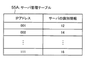
図3には、管理装置10の2次記憶装置40に記憶されたサーバ管理テーブル55Aが示される。図3に示すように、サーバ管理テーブル55Aには、IPアドレスとサーバの識別情報とが対応して記憶されている。
FIG. 3 shows a server management table 55A stored in the
なお、ロードバランサ20及びクラウド管理装置25の構成は、管理装置10の構成と同様であるので、それらの説明を省略する。
Note that the configurations of the
図4には、スイッチ18のブロック図が示される。図4に示すように、スイッチ18は、CPU62、ROM64、及びメモリ66を備える。CPU62、ROM64、及びメモリ66はバス68に接続される。バス68には、複数のポート70〜78が接続される。ポート70にはロードバランサ20が接続される。ポート72にはネットワーク22が接続される。ポート74には、サーバ12が接続される。ポート76には、サーバ14が接続される。ポート78には、サーバ16が接続される。
FIG. 4 shows a block diagram of the
図5には、第1実施形態の管理装置10の機能部が示される。図5に示すように、管理装置10は、取得部82、検索部84、及び表示部86を備える。
FIG. 5 shows functional units of the
取得部82、検索部84はそれぞれ、本発明の取得部、特定部の一例である。
The
図6には、サーバ識別情報特定プログラムにおけるプロセスが示される。図6に示すように、サーバ識別情報特定プログラムは、取得プロセス83、検索プロセス85、及び表示プロセス87を有する。サーバ識別情報特定プログラムは、ROM34に記憶されており、CPU32によりROM34から読み出され、メモリ36に展開されて、実行される。
FIG. 6 shows a process in the server identification information specifying program. As shown in FIG. 6, the server identification information specifying program has an
なお、ここではサーバ識別情報特定プログラムをROM34から読み出す場合を例示したが、必ずしも最初からROM34に記憶させておく必要はない。例えば、管理装置10に接続されて使用されるSSD(Solid State Drive)、DVDディスク、ICカード、光磁気ディスク、CD−ROMなどの任意の「可搬型の記憶媒体」に先ずはサーバ識別情報特定プログラムを記憶させておいてもよい。そして、管理装置10がこれらの可搬型の記憶媒体からサーバ識別情報特定プログラムを取得して実行するようにしてもよい。また、通信回線を介して管理装置10に接続される他のコンピュータ又はサーバ装置等の記憶部にサーバ識別情報特定プログラムを記憶させておいてもよい。この場合、管理装置10は他のコンピュータ又はサーバ装置等からサーバ識別情報特定プログラムを取得して実行する。
Although the case where the server identification information specifying program is read from the
なお、CPU32が、上記プロセス83〜87の各々を実行することにより、図5の上記各部82〜86として動作する。
The
次に、第1実施形態の作用を説明する。 Next, the operation of the first embodiment will be described.
複数のサーバ12〜16の各々は、クラウド管理装置25により管理される。クラウド管理装置25は、サーバを利用してサービスを提供しようとするサービス提供者に、サービス提供者が指定した個数のサーバを提供する。例えば、サービス提供者があるサービスを提供するため、クラウド管理装置25に2個のサーバを提供するように要求したとする。クラウド管理装置25は、複数のサーバ12〜16の中から2つのサーバを選択し、選択された2つのサーバのIPアドレスを、サービス提供者が提供するサービスに対する要求を送信する送信先IPアドレス(負荷分散情報)として、ロードバランサ20に登録する。ロードバランサ20は、サービス提供者が提供するサービス、例えば、ホームページのデータを送信するサービスの実行要求を複数受け付け、受け付けた複数の要求の各々を、登録された2つのIPアドレスに対応する2つのサーバに割り振る。例えば、2つのIPアドレスを、001と111とし、IPアドレス=001はサーバ12に対応し、IPアドレス=111はサーバ16に対応するとする。
Each of the plurality of
ロードバランサ20は、複数の要求の各々を、IPアドレス=001と、IPアドレス=111との何れかに割り振る。IPアドレス=001と、IPアドレス=111との何れかに割り振られた要求は、スイッチ18を介して、サーバ12又はサーバ16に割り振られる。サーバ12及びサーバ16は、割り振られた要求に従って、ホームページのデータを送信する。よって、サーバ12及びサーバ16は、冗長化される。なお、ロードバランサ20は、登録された負荷分散情報から、冗長化されるサーバのIPアドレスを知ることができる。しかし、ロードバランサ20は、当該IPアドレスに対応するサーバがどのサーバなのかは知らない。
The
図7には、第1実施形態のサーバ識別情報特定処理の一例がフローチャートとして示される。図7のステップ92で、取得部82は、ロードバランサ20から、冗長化されるサーバのIPアドレス(負荷分散情報)である、001、111を取得する。
FIG. 7 shows a flowchart of an example of the server identification information specifying process of the first embodiment. In
ステップ94で、検索部84は、管理装置10の2次記憶装置40に記憶されたサーバ管理テーブル55Aから、ステップ92で取得したIPアドレス、即ち、001、111に対応して記憶されたサーバの識別情報、即ち、12、16を検索する。
In
ステップ96で、表示部86は、表示制御部46を制御して、上記検索されたサーバの識別情報、即ち、12、16により識別されるサーバ12、16を表示装置48の画面に表示する。
In
次に、第1実施形態の効果を説明する。 Next, effects of the first embodiment will be described.
第1実施形態では、サーバ管理テーブル55Aに、複数のサーバ12〜16の各々の識別情報と複数のサーバ12〜16の各々のIPアドレスとが対応して記憶される。ロードバランサ20から、冗長化されるサーバのIPアドレスを取得し、取得したIPアドレスに対応するサーバの識別情報をサーバ管理テーブル55Aから検索する。よって、冗長化されるサーバを知ることができる。
In the first embodiment, the identification information of each of the plurality of
次に、第1実施形態の変形例を説明する。 Next, a modification of the first embodiment will be described.
(第1変形例)
第1実施形態では、複数のサーバ12〜16の各々の識別情報と複数のサーバ12〜16の各々のIPアドレスとを対応して記憶するサーバ管理テーブル55Aを、管理装置10内の2次記憶装置40に記憶する。第1変形例では、サーバ管理テーブル55Aを、例えば、サーバ12に記憶する。ステップ94の処理では、サーバ12からサーバ管理テーブル55Aの内容を受信し、受信した内容から、取得部82が取得したIPアドレスに対応するサーバの識別情報を検索することができる。
(First modification)
In the first embodiment, the server management table 55A that stores the identification information of each of the plurality of
(第2変形例)
第1実施形態では、ロードバランサ20を装置であるとした。第2変形例では、ロードバランサ20をプログラムとしていずれかの装置、例えばサーバ12にインストールすることができる。そして、サーバ12がプログラムを実行することにより、上記要求を割り振ることができる。この点、後述する第2実施形態〜第4実施形態も同様である。
(Second modification)
In the first embodiment, the
[第2実施形態]
図8には、第2実施形態のサービス提供システムが示される。図8に示すように、第2実施形態のサービス提供システムは、各々ネットワーク22に接続された、管理装置10、複数のサーバシステム160、162・・・164、及びクラウド管理装置25を備える。複数のサーバシステム160、162・・・164の各々は互いに同様な構成であるので、以下、サーバシステム160の構成のみ説明する。サーバシステム160は、ロードバランサ20、ロードバランサ20に接続されたスイッチ18、及び、スイッチ18に接続された複数のサーバ12〜16、106〜108を備える。以上の各装置12〜16、106〜108、18、20はネットワーク22に接続される。以上の各装置10、12〜16、106〜108、18、20は、第1実施形態の対応する装置と同様の構成であるので、それらの詳細な説明は省略する。
[Second Embodiment]
FIG. 8 shows a service providing system according to the second embodiment. As illustrated in FIG. 8, the service providing system according to the second embodiment includes a
なお、スイッチ18には、複数のポート70、72、74〜78、102〜104が設けられる。ポート70、72のそれぞれには、ロードバランサ20、ネットワーク22が接続される。ポート74〜78のそれぞれには、サーバ12〜16が接続される。ポート102〜104のそれぞれには、サーバ106〜108が接続される。
The
図9(A)には、管理装置10の2次記憶装置40に記憶されたロードバランサ管理テーブル53Aが示されている。ロードバランサ管理テーブル53Aには、以下の第1〜第3の3種類の識別情報が対応して記憶される。第1に、サーバシステム160、162・・・164の識別情報がロードバランサ管理テーブル53Aに記憶される。第2に、サーバシステム160、162・・・164内のロードバランサ20の識別情報がロードバランサ管理テーブル53Aに記憶される。第3に、ロードバランサ20が接続されるスイッチ18の識別情報がロードバランサ管理テーブル53Aに記憶される。
FIG. 9A shows a load balancer management table 53A stored in the
図9(B)には、管理装置10の2次記憶装置40に記憶された、サーバシステム160におけるサーバ管理テーブル55Bが示されている。図9(B)に示すように、サーバ管理テーブル55Bには、各サーバ12〜16、106〜108の識別情報、及び各サーバ12〜16、106〜108のIPアドレスが対応して記憶される。また、サーバ管理テーブル55Bには、各サーバ12〜16、106〜108が設けられた棚の識別情報(たな情報)が対応して記憶される。管理装置10の2次記憶装置40には、サーバシステム160以外の他のサーバシステム162・・・164におけるサーバ管理テーブルが記憶される。なお、他のサーバシステム162・・・164における各サーバ管理テーブルは、サーバシステム160におけるサーバ管理テーブル55Bと同様であるので、それらの説明を省略する。
FIG. 9B shows a server management table 55B in the
図10には、サーバシステム160におけるスイッチ18のメモリ66に記憶されたポート管理テーブル57が示される。ポート管理テーブル57には、スイッチ18の各ポート70、72、74〜78、102〜104の識別情報が記憶される。また、ポート管理テーブル57には、各ポート70、72、74〜78、102〜104に設定されたネットワーク識別子(VLAN ID=1000、2000)がポート70、72、74〜78、102〜104に対応して記憶される。更に、ポート管理テーブル57には、各ポート70、72、74〜78、102〜104が接続する接続先の装置の識別情報が各ポート70、72、74〜78、102〜104に対応して記憶される。例えば、ポート70の識別情報=70、ポート70に設定されたネットワーク識別子(VLAN ID)=1000、及びポート70の接続先であるロードバランサ20の識別情報=20が対応して記憶される。
FIG. 10 shows the port management table 57 stored in the
ここで、ネットワーク識別子(VLAN ID)について説明する。VLAN(Virtual Local Area Network) は仮想ネットワークを意味し、VLAN IDは、仮想ネットワークの識別情報である。ポートにVLAN IDが設定されると、スイッチ18は、当該ポートに設定されたVLAN IDに対応するパケットデータのみを当該ポートを介して転送させる。よって、同じVLAN IDが設定されたポートに接続された各装置については、物理的なネットワーク22と独立した仮想的なネットワークが形成される。ポート70、74〜78には、同じVLAN ID=1000が設定される。よって、図8に示すように、ロードバランサ20とサーバ12〜16について第1の仮想的なネットワークが形成される。ポート102〜104には、同じVLAN ID=2000が設定される。よって、図8に示すように、サーバ106〜108について第2の仮想的なネットワークが形成される。
Here, the network identifier (VLAN ID) will be described. VLAN (Virtual Local Area Network) means a virtual network, and VLAN ID is identification information of a virtual network. When the VLAN ID is set for the port, the
このように、サーバ12〜16について第1の仮想的なネットワークが形成され、サーバ106〜108について第2の仮想的なネットワークが形成される。図9(B)に示すように、例えば、サーバ12とサーバ106のそれぞれのIPアドレスが互いに同じであっても、サーバ12とサーバ106が接続するスイッチ18のポート74、102には異なるVLAN IDが設定される。よって、パケットデータは、サーバ12とサーバ106の何れか対応するサーバにのみ受信される。
In this way, a first virtual network is formed for the
図11には、第2実施形態の管理装置10の機能部が示される。図11に示すように、管理装置10は、負荷分散情報取得部112、スイッチ識別情報取得部114、ネットワーク識別子取得部116、サーバ識別情報取得部118、情報解析部120、情報記憶部122、及び表示部124を備える。
FIG. 11 shows functional units of the
図12には、第2実施形態のサーバ識別情報特定プログラムにおけるプロセスが示される。サーバ識別情報特定プログラムは、負荷分散情報取得プロセス113、スイッチ識別情報取得プロセス115、ネットワーク識別子取得プロセス117、及びサーバ識別情報取得プロセス119を備える。サーバ識別情報特定プログラムは、情報解析プロセス121、情報記憶プロセス123、及び表示プロセス125を備える。
FIG. 12 shows processes in the server identification information specifying program of the second embodiment. The server identification information specifying program includes a load distribution
なお、CPU32が、上記プロセス113〜125の各々を実行することにより、図11の上記各部112〜124として動作する。
The
次に、第2実施形態の作用を説明する。 Next, the operation of the second embodiment will be described.
図13には、第2実施形態のサーバ識別情報特定処理の一例がフローチャートとして示される。図13のステップ126で、情報解析部120は、複数のサーバシステム160、162・・・164の各々を識別する変数mを0に初期化し、ステップ127で、情報解析部120は、変数mを1インクリメントする。ステップ128で、詳細には後述する、変数mで識別されるサーバシステム内の冗長構成を表示する冗長構成表示処理が実行される。ステップ129で、情報解析部120は、変数mが、複数のサーバシステム160、162・・・164の総数Mに等しいか否かを判断する。
FIG. 13 shows a flowchart of an example of the server identification information specifying process of the second embodiment. In
ステップ129の判定結果が否定判定の場合には、冗長構成表示処理が実行されていないサーバシステムがあるので、サーバ識別情報特定処理は、ステップ127に戻る。ステップ129の判定結果が肯定判定の場合には、全てのサーバシステムについて冗長構成表示処理が実行されたので、サーバ識別情報特定処理は終了する。
If the determination result of
図14には、図13のステップ128の冗長構成表示処理の一例がフローチャートとして示される。図14のステップ132で、負荷分散情報取得部112は、ロードバランサ管理テーブル53A(図9(A))を参照して、変数mで識別されるサーバシステム内のロードバランサを特定する。そして、負荷分散情報取得部112は、特定したロードバランサ20から負荷分散情報である、IPアドレスを取得する。例えば、IPアドレスとして、001、111が取得されたとする。ステップ134で、スイッチ識別情報取得部114は、ロードバランサ管理テーブル53A(図9(A))を参照して、変数mで識別されるサーバシステムにおけるロードバランサ20と接続するスイッチ18の識別情報を取得する。
FIG. 14 is a flowchart showing an example of the redundant configuration display process in
ステップ132の処理は、本発明の取得部の処理の一例である。
The process of
ステップ136で、ネットワーク識別子取得部116は、ステップ134で取得された識別情報により識別されるスイッチ18から、変数mで識別されるサーバシステムにおけるロードバランサ20が接続されるポートに設定されたネットワーク識別子を取得する。より詳細に説明する。ネットワーク識別子取得部116は、ステップ134で取得された識別情報により識別されるスイッチ18に対し、変数mで識別されるサーバシステムにおけるロードバランサ20が接続されるポートに設定されたネットワーク識別子を送信するように指示する。当該スイッチ18は、ポート管理テーブル57(図10)を参照して、ロードバランサ20が接続されるポート70を識別し、ポート70に対応して記憶されたネットワーク識別子(VLAN ID=1000)を読み取る。当該スイッチ18は、読み取ったVLAN ID=1000を、管理装置10に送信する。ネットワーク識別子取得部116は、VLAN ID=1000を受信することにより、変数mで識別されるサーバシステムにおけるロードバランサ20が接続されるポートに設定されたネットワーク識別子(VLAN ID=1000)を取得する。
In
ステップ138で、サーバ識別情報取得部118は、ステップ136で取得されたネットワーク識別子(VLAN ID=1000)で識別されるVLANと同じVLANに属するポートに接続されたサーバの識別情報を取得する。より詳細に説明する。サーバ識別情報取得部118は、ステップ134で取得された識別情報により識別されるスイッチ18に対し、次の指示をする。即ち、サーバ識別情報取得部118は、ステップ136で取得されたネットワーク識別子(VLAN ID=1000)で識別されるVLANと同じVLANに属するポートに接続されたサーバの識別情報を送信するように指示する。当該スイッチ18は、ポート管理テーブル57(図10)を参照して、VLAN ID=1000が設定されたポートの識別情報に対応して記憶されたサーバ(接続先)の識別情報(12、14・・・16)を読み出す。当該スイッチ18は、読み出したサーバの識別情報(12、14・・・16)を、管理装置10に送信する。サーバ識別情報取得部118は、サーバの識別情報(12、14・・・16)を受信する。これより、サーバ識別情報取得部118は、ステップ136で取得されたネットワーク識別子(VLAN ID=1000)で識別されるVLANと同じVLANに属するポートに接続されたサーバの識別情報を取得する。
In
ステップ140で、情報解析部120は、ステップ138で取得されたサーバの識別情報を識別する変数sを初期化し、ステップ142で、情報解析部120は、変数sを1インクリメントする。ステップ144で、情報解析部120は、変数sで識別されるサーバの識別情報により識別されるサーバが、負荷分散情報に基づいて負荷が分散されるサーバか否かを判断する。より詳細に説明すると、情報解析部120は、サーバ管理テーブル55B(図9(B))を参照して、変数sで識別されるサーバの識別情報に対応するIPアドレスを読み出す。情報解析部120は、読み出したIPアドレスと、ステップ132で取得された負荷分散情報であるIPアドレスの何れかとが同じか否かを判断する。
In
ここで、変数sで識別されるサーバの識別情報が12の場合、サーバ管理テーブル55B(図9(B))には、サーバの識別情報=12に対応して、IPアドレス=001が記憶されている。上記のようにステップ132で、負荷分散情報であるIPアドレスとして001、111が取得されたとすると、サーバの識別情報=12に対応するIPアドレス=001は、ステップ132で取得されたIPアドレス=001と等しい。よって、ステップ144の判定結果は肯定判定である。
When the server identification information identified by the variable s is 12, the server management table 55B (FIG. 9B) stores the IP address = 001 corresponding to the server identification information = 12. ing. As described above, assuming that 001 and 111 are acquired as IP addresses that are load distribution information in
ステップ144の判定結果が肯定判定の場合には、変数sで識別されるサーバの識別情報により識別されるサーバは冗長化されたサーバの1つである。ステップ146で、情報記憶部122は、変数sで識別されるサーバの識別情報を2次記憶装置40の図示しない冗長構成記録領域に記憶する。その後、冗長構成表示処理はステップ148に進む。
If the determination result in
一方、変数sで識別されるサーバの識別情報が14の場合、サーバ管理テーブル55B(図9(B))には、サーバの識別情報=14に対応して、IPアドレス=002が記憶されている。上記のようにステップ132で、IPアドレスとして001、111が取得されたとすると、サーバの識別情報=14に対応するIPアドレス=002は、ステップ132で取得されたIPアドレスとは異なる。よって、ステップ144の判定結果は否定判定である。
On the other hand, when the server identification information identified by the variable s is 14, the server management table 55B (FIG. 9B) stores the IP address = 002 corresponding to the server identification information = 14. Yes. As described above, assuming that 001 and 111 are acquired as IP addresses in
ステップ144の判定結果が否定判定の場合には、変数sで識別されるサーバの識別情報により識別されるサーバは冗長化されたサーバではないので、ステップ146がスキップされて、冗長構成表示処理はステップ148に進む。
If the determination result in
ステップ148で、情報解析部120は、変数sが、ステップ138で取得されたサーバの識別情報の総数S0に等しいか否かを判断する。ステップ148の判定結果が否定判定の場合には、サーバの識別情報により識別されるサーバが冗長化されたサーバの1つか否かが判断されていないサーバの識別情報があるので、冗長構成表示処理はステップ142に戻る。
In
一方、ステップ148の判定結果が肯定判定の場合には、全てのサーバの識別情報について、サーバの識別情報により識別されるサーバが冗長化されたサーバの1つか否かが判断されたので、冗長構成表示処理はステップ152に進む。
On the other hand, if the determination result in
ステップ152で、表示部124は、表示する項目(物理的配置)、例えば、上記棚の情報を取得する。ステップ154で、表示部124は、2次記憶装置40の図示しない冗長構成記録領域に記憶された冗長化されたサーバの識別情報を取得し、対応する棚と組み合わせて表示する。より詳細に説明する。表示部124は、サーバ管理テーブル55B(図9(B))を参照して、冗長構成記録領域に記憶された冗長化されたサーバの識別情報に対応するたな情報を取得する。表示部124は、サーバ12〜16、106〜108が設けられた棚を表示すると共に、取得したたな情報により識別される棚の位置に、冗長化されたサーバを強調表示する。
In
ステップ134〜146の処理は、本発明の特定部の処理の一例である。
The processing of
次に、第2実施形態の効果を説明する。 Next, effects of the second embodiment will be described.
上記のように同じIPアドレスであってもVLANが違えば、冗長化されたサーバではない。よって、これらを区別する必要がある。そこで、第2実施形態では、各サーバの識別情報に対応して、第1に、サーバ管理テーブル55B(図9(B))に、IPアドレスが記憶され、第2に、ポート管理テーブル57(図10)にネットワーク識別子が記憶される。スイッチ識別情報取得部114がロードバランサ20から冗長化されたサーバのIPアドレスを取得する。スイッチ識別情報取得部114が、ロードバランサ20が接続されるスイッチ18のポート70に設定されたネットワーク識別子を取得する。管理装置10は、上記サーバ管理テーブル55B(図9(B))及びポート管理テーブル57(図10)から、取得された冗長化されたサーバのIPアドレス及びネットワーク識別子の各々に対応するサーバの識別情報を取得する。よって、冗長化されるサーバを知ることができる。
As described above, even if the IP address is the same, if the VLAN is different, it is not a redundant server. Therefore, it is necessary to distinguish these. Therefore, in the second embodiment, corresponding to the identification information of each server, first, the IP address is stored in the server management table 55B (FIG. 9B), and secondly, the port management table 57 ( The network identifier is stored in FIG. The switch identification
次に、第2実施形態の変形例を説明する。 Next, a modification of the second embodiment will be described.
第2実施形態では、サーバ管理テーブル55B(図9(B))を管理装置10の2次記憶装置40に、ポート管理テーブル57(図10)をスイッチ18のメモリ66に設けている。変形例では、サーバ管理テーブル55B(図9(B))及びポート管理テーブル57(図10)を管理装置10の2次記憶装置40に設けることができる。
In the second embodiment, the server management table 55B (FIG. 9B) is provided in the
[第3実施形態]
図15には、第3実施形態のサービス提供システムが示される。第3実施形態のサービス提供システムの構成(図15)は、上記第2実施形態のサービス提供システム(図8)と同様の構成があるので、同一部分には同一の符号を付して、異なる部分について説明する。
[Third Embodiment]
FIG. 15 shows a service providing system according to the third embodiment. The configuration of the service providing system according to the third embodiment (FIG. 15) is similar to the configuration of the service providing system according to the second embodiment (FIG. 8). The part will be described.
図8に示す第2実施形態のサービス提供システムでは、ロードバランサ20と複数のサーバ12〜16、106〜108とが1つのスイッチ18を介して接続される。これに対し、図15に示す第3実施形態のサービス提供システムでは、ロードバランサ20と複数のサーバ12〜16、106〜108とが複数のスイッチ182〜196を介して接続される。即ち、サーバ12、14は、スイッチ186、182を介して、ロードバランサ20に接続される。サーバ16は、スイッチ194、184、182を介して、ロードバランサ20に接続される。サーバ106、108は、スイッチ196、184、182を介して、ロードバランサ20に接続される。
In the service providing system according to the second embodiment shown in FIG. 8, the
図16には、管理装置10の2次記憶装置40に記憶されたロードバランサ管理テーブル53Aが示されている。ロードバランサ管理テーブル53Aは、図9(A)と同様であるので、その説明を省略する。
FIG. 16 shows a load balancer management table 53A stored in the
図17には、管理装置10の2次記憶装置40に記憶された、サーバシステム160に対応するサーバ管理テーブル55Cが示されている。サーバ管理テーブル55Cには、各サーバ12〜16、106〜108の識別情報、各サーバ12〜16、106〜108のIPアドレス、各サーバ12〜16、106〜108が接続するスイッチ及びポートの識別情報が対応して記憶される。サーバ管理テーブル55Cには、各サーバ12〜16、106〜108の識別情報に対応してたな情報も記憶されている。例えば、サーバ12の識別情報=12、サーバ12のIPアドレス=001、サーバ12が接続されるスイッチ186の識別情報=186、及びスイッチ186におけるサーバ12が接続されるポート236の識別情報=236が対応して記憶される。また、サーバ12の識別情報=12に対応して、サーバ12が配置された棚のたな情報=T1が記憶される。なお、管理装置10の2次記憶装置40には、サーバシステム160以外の他のサーバシステム162・・・164に対応するサーバ管理テーブルが記憶される。なお、他のサーバシステム162・・・164における各サーバ管理テーブルは、サーバシステム160におけるサーバ管理テーブル55Cと同様であるので、それらの説明を省略する。
FIG. 17 shows a server management table 55C corresponding to the
図18(A)〜(E)には、各スイッチ182〜196におけるポート管理テーブル182T〜196Tが示される。ポート管理テーブル182T〜196Tは互いに同様の種類の情報を記憶するので、以下、図18(A)に示す、スイッチ182のメモリ66に記憶されるポート管理テーブル182Tのみ説明する。図18(A)に示すように、ポート管理テーブル182Tには、スイッチ182の各ポート202〜212の識別情報が記憶される。また、ポート管理テーブル182Tには、各ポート202〜212に設定されたVLAN IDが各ポート202〜212に対応して記憶される。更に、ポート管理テーブル182Tには、各ポート202〜212が接続する接続先の装置の識別情報が各ポート202〜212に対応して記憶される。例えば、ポート202の識別情報=202、ポート202に設定されたVLAN ID=1000、及びポート202の接続先であるロードバランサ20の識別情報=20が対応して記憶される。
18A to 18E show port management tables 182T to 196T in the
第3実施形態の管理装置10のサーバ識別情報特定プログラムの具体的内容は、第2実施形態の管理装置10のサーバ識別情報特定プログラムと異なる。しかし、第3実施形態の管理装置10のサーバ識別情報特定プログラムにおける機能部は、第2実施形態の機能部と同様であるので、その説明を省略する。
The specific contents of the server identification information specifying program of the
第3実施形態の管理装置10のサーバ識別情報特定プログラムのプロセスの具体的内容は、第2実施形態の管理装置10のサーバ識別情報特定プログラムと異なる。しかし、第3実施形態の管理装置10のサーバ識別情報特定プログラムにおけるプロセスのブロックは、第2実施形態の機能部と同様であるので、その説明を省略する。
The specific contents of the process of the server identification information specifying program of the
次に、第3実施形態の作用を説明する。第3実施形態の作用は、第2実施形態の作用と同様の部分があるので、以下、異なる部分について説明する。第3実施形態でも、第2実施形態のサーバ識別情報特定処理(図13参照)が実行される。 Next, the operation of the third embodiment will be described. Since there exists a part similar to the effect | action of 2nd Embodiment, the effect | action of 3rd Embodiment is demonstrated below about a different part. Also in the third embodiment, the server identification information specifying process (see FIG. 13) of the second embodiment is executed.
図13のステップ128の冗長構成表示処理は、第3実施形態と第2実施形態とで異なる。図19には、第3実施形態における冗長構成表示処理の一例がフローチャートとして示される。図19のステップ132〜136は、第2実施形態のサーバ識別情報特定処理(図13参照)のステップ132〜136と同様であるので、その詳細な説明を省略する。
The redundant configuration display process in
ステップ132の処理が実行されることにより、例えば、ロードバランサ20からIPアドレス(負荷分散情報)として、001、111が取得されたとする。
It is assumed that, for example, 001 and 111 are acquired as IP addresses (load distribution information) from the
ステップ132の処理は、本発明の取得部の処理の一例である。
The process of
また、ステップ134及びステップ136の処理が実行されることにより、例えば、変数mで識別されるサーバシステムにおけるロードバランサ20が接続されるポート202に設定されたネットワーク識別子(VLAN ID=1000)が取得されたとする。
Further, by executing the processing of
ステップ262で、サーバ識別情報取得部118は、サーバ管理テーブル55C(図17)から、ステップ132で取得されたIPアドレス(負荷分散情報)に対応するサーバの識別情報を検索する。上記のように、IPアドレス(負荷分散情報)として、001、111が取得された場合、ステップ262では、サーバの識別情報=12、16、106、108が取得される。
In
ステップ264で、情報解析部120は、ステップ262で取得されたサーバの識別情報を識別する変数dを0に初期化し、ステップ266で、情報解析部120は、変数dを1インクリメントする。
In
ステップ268で、情報解析部120は、変数dで識別される識別情報により識別されるサーバが接続するスイッチから、当該サーバが接続するポートのネットワーク識別子(VLAN ID)を取得する。より詳細に説明すると、情報解析部120は、サーバ管理テーブル55C(図17)から、変数dで識別される識別情報に対応するスイッチ及びポートの識別情報を取得する。情報解析部120は、取得したスイッチの識別情報により識別されるスイッチに、取得したポートの識別情報により識別されるポートに設定されたVLAN IDを送信するように指示する。当該指示を受けたスイッチは、当該スイッチのメモリ66に記憶されたポート管理テーブルから、当該ポートに設定されたVLAN IDを、管理装置10に送信する。スイッチからVLAN IDを受信することにより、変数dで識別されるサーバが接続するポートのネットワーク識別子(VLAN ID)を取得する。
In
例えば、変数dでサーバの識別情報=12が識別されるとする。サーバ管理テーブル55C(図17)から識別情報=12に対応するスイッチの識別情報=186及びポートの識別情報=236が取得される。情報解析部120は、取得したスイッチの識別情報=186により識別されるスイッチ186に、取得したポートの識別情報=236により識別されるポート236に設定されたVLAN IDを送信するように指示する。当該指示を受けたスイッチ186は、当該スイッチのメモリ66に記憶されたポート管理テーブル186T(図18(C))から、当該ポート236に設定されたVLAN ID=1000を、管理装置10に送信する。スイッチ186からVLAN ID=1000を受信することにより、サーバ12が接続するポート236のネットワーク識別子(VLAN ID=1000)を取得する。
For example, it is assumed that server identification information = 12 is identified by the variable d. Switch identification information = 186 and port identification information = 236 corresponding to identification information = 12 are acquired from the server management table 55C (FIG. 17). The
ステップ270で、情報解析部120は、ステップ268で取得されたネットワーク識別子(VLAN ID)が、ステップ136で取得されたネットワーク識別子(VLAN ID)と同じか否かを判断する。
In
ステップ270の判定結果が肯定判定の場合には、変数dで識別されるサーバの識別情報により識別されるサーバは冗長化されたサーバの1つである。そこで、ステップ272で、情報記憶部122は、変数dで識別されるサーバの識別情報dを2次記憶装置40の図示しない冗長構成記録領域に記憶する。その後、冗長構成表示処理はステップ274に進む。
If the determination result in
一方、ステップ270の判定結果が否定判定の場合には、変数dで識別されるサーバの識別情報により識別されるサーバは冗長構成されたサーバではないので、ステップ272がスキップされて、冗長構成表示処理はステップ274に進む。
On the other hand, if the determination result in
ステップ274で、情報解析部120は、変数dが、ステップ262で取得されたサーバの識別情報の総数Dに等しいか否かを判断する。ステップ274の判定結果が否定判定の場合には、サーバの識別情報により識別されるサーバが、冗長化されたサーバの1つか否かが判断されていないサーバの識別情報があるので、冗長構成表示処理はステップ266に戻る。
In
一方、ステップ274の判定結果が肯定判定の場合には、全てのサーバの識別情報について、サーバの識別情報により識別されるサーバが冗長化されたサーバの1つか否かが判断されたので、冗長構成表示処理はステップ276に進む。
On the other hand, if the determination result in
ステップ276で、表示部124は、表示制御部46を制御して、表示装置48の画面に、冗長化されたサーバを表示する。具体的には、表示部124は、冗長構成記録領域に記憶された冗長化されたサーバの識別情報に対応するたな情報を取得する。表示部124は、サーバ12〜16、106〜108が設けられた棚を表示すると共に、取得したたな情報により識別される棚の位置に、冗長化されたサーバを強調表示する。
In
ステップ134〜272の処理は、本発明の特定部の処理の一例である。
The processing of
次に、第3実施形態の効果を説明する。 Next, effects of the third embodiment will be described.
上記のように同じIPアドレスであってもVLANが違えば、冗長化されたサーバではない。よって、これらを区別する必要がある。第3実施形態では、各サーバの識別情報に対応して、第1にサーバ管理テーブル55C(図17)に、IPアドレス、スイッチ及びポートの識別情報が記憶され、第2に、各ポート管理テーブル(図18)の各ポートに対応してネットワーク識別子が記憶される。スイッチ識別情報取得部114がロードバランサ20から冗長化されたサーバのIPアドレスを取得する。スイッチ識別情報取得部114が、ロードバランサ20が接続されるスイッチ18のポート70に設定されたネットワーク識別子を取得する。管理装置10は、上記サーバ管理テーブル55C及びポート管理テーブルから、取得された冗長化されたサーバのIPアドレス及びロードバランサ20が接続されるスイッチのポートに設定されたネットワーク識別子の各々に対応するサーバの識別情報を取得する。よって、冗長化されるサーバを知ることができる。
As described above, even if the IP address is the same, if the VLAN is different, it is not a redundant server. Therefore, it is necessary to distinguish these. In the third embodiment, corresponding to the identification information of each server, first, the server management table 55C (FIG. 17) stores IP address, switch and port identification information, and secondly, each port management table. A network identifier is stored corresponding to each port in FIG. The switch identification
ここで、第2実施形態と第3実施形態の作用の違いを説明する。 Here, the difference in operation between the second embodiment and the third embodiment will be described.
第2実施形態では、第1に、ネットワーク識別子取得部116は、ロードバランサ20が接続されるスイッチ18のポート70に設定されたネットワーク識別子(VLAN ID)=1000が設定されたポートに接続されたサーバの識別情報を取得する。第2に、情報解析部120は、ネットワーク識別子(VLAN ID)=1000が設定されたポートに接続されたサーバの中から、負荷分散情報であるIPアドレスに対応するサーバの識別情報を取得する。
In the second embodiment, first, the network
これに対し、第3実施形態では、第1に、サーバ識別情報取得部118は、負荷分散情報であるIPアドレスに対応するサーバの識別情報を取得する。第2に、情報解析部120は、負荷分散情報であるIPアドレスに対応するサーバの識別情報の中から、ロードバランサ20が接続されるスイッチ18のポート70に設定されたネットワーク識別子が設定されたポートに接続されたサーバを取得する。
In contrast, in the third embodiment, first, the server identification
つまり、第2実施形態では、ネットワーク識別子、及び負荷分散情報であるIPアドレスの順に冗長化されたサーバの候補を絞る。これに対し、第3実施形態では、負荷分散情報であるIPアドレス、及びネットワーク識別子の順に冗長化されたサーバの候補を絞る点で相違する。 That is, in the second embodiment, redundant server candidates are narrowed down in the order of the network identifier and the IP address that is the load distribution information. On the other hand, the third embodiment is different in that it narrows down server candidates that are made redundant in the order of the IP address, which is load balancing information, and the network identifier.
次に、第3実施形態の変形例を説明する。 Next, a modification of the third embodiment will be described.
第3実施形態では、サーバ管理テーブル55C(図17)を管理装置10の2次記憶装置40に、ポート管理テーブル(図18)を各スイッチのメモリ66に設けている。変形例では、サーバ管理テーブル55C(図17)及びポート管理テーブル(図18)を管理装置10の2次記憶装置40に設けることができる。
In the third embodiment, the server management table 55C (FIG. 17) is provided in the
[第4実施形態]
図20には、第4実施形態のサービス提供システムが示される。図20に示すように、第4実施形態のサービス提供システムは、各々ネットワーク22に接続された、管理装置10、複数のサーバシステム420、422・・・424、及びクラウド管理装置25を備える。複数のサーバシステム420、422・・・424の各々は互いに同様な構成であるので、以下、サーバシステム420の構成のみ説明する。サーバシステム420は、ロードバランサ20を備える。ロードバランサ20には、スイッチ400が接続される。スイッチ400には、複数のサーバ201〜206が接続されたスイッチ401が接続される。スイッチ401には、複数のサーバ301〜306が接続されたスイッチ402が接続される。
[Fourth Embodiment]
FIG. 20 shows a service providing system according to the fourth embodiment. As illustrated in FIG. 20, the service providing system according to the fourth embodiment includes a
ロードバランサ20は、スイッチ400のポート411に接続される。スイッチ400のポート412、413はそれぞれ、スイッチ402のポート318、スイッチ401のポート218に接続される。スイッチ400のポート414は、ネットワーク22に接続される。ポート411、412、413には、VLAN ID=2500と、セグメントの識別情報のSegment ID=3000(詳細は後述)とが設定される。
The
スイッチ401のポート219はネットワーク22に接続される。ポート211〜216には、サーバ201〜206が接続される。ポート217はスイッチ402のポート317に接続される。ポート211、214〜216には、VLAN ID=2500が設定される。ポート212、213には、VLAN ID=1500が設定される。ポート211〜219には、Segment ID=3000が設定される。
A
スイッチ402のポート311〜316には、サーバ301〜306が接続される。ポート318はスイッチ400のポート412に接続される。ポート317には、スイッチ401のポート217が接続される。ポート319は、ネットワーク22に接続される。
ポート311〜313には、VLAN ID=1500が設定される。ポート314〜316には、VLAN ID=2500が設定される。ポート311〜319には、Segment ID=3000が設定される。
VLAN ID = 1500 is set in the
ここで、Segmentは、内部に少なくとも1つの仮想ネットワークを備えた二次仮想ネットワークを示し、Segment IDは、二次仮想ネットワークの識別情報である。例えば、図20における二次仮想ネットワーク(Segment ID=3000)内には、VLAN ID=1500の第1仮想ネットワークと、VLAN ID=2500の第2仮想ネットワークとが含まれる。 Here, “Segment” indicates a secondary virtual network provided with at least one virtual network therein, and “Segment ID” is identification information of the secondary virtual network. For example, the secondary virtual network (Segment ID = 3000) in FIG. 20 includes a first virtual network with VLAN ID = 1500 and a second virtual network with VLAN ID = 2500.
次に、管理装置10の2次記憶装置40に記憶される種々のテーブル(図21〜26)を説明する。
Next, various tables (FIGS. 21 to 26) stored in the
図21には、第4実施形態のサーバ管理テーブル55Dが示される。サーバ管理テーブル55Dには、サーバシステム420〜424に含まれるすべてのサーバについて、IPアドレス、対象サーバ、対象のサーバが設けられた筐体、及びテナント情報の識別情報が対応して記憶される。テナントは、提供されたサーバを介してサービスを実行する会社等である。
FIG. 21 shows a server management table 55D of the fourth embodiment. In all of the servers included in the
図22には、第4実施形態の負荷分散情報管理テーブル59が示される。負荷分散情報管理テーブル59には、各サーバシステムにおける、要求を分散させる処理に対応して、要求の送信先IPアドレス、すなわち、冗長化されたサーバのIPアドレスが記憶される。なお、説明の簡単のため、図22には、各サーバシステムでは、1組の冗長構成が存在する例が示される。 FIG. 22 shows a load distribution information management table 59 of the fourth embodiment. The load distribution information management table 59 stores the transmission destination IP address of the request, that is, the IP address of the redundant server, corresponding to the process of distributing the request in each server system. For ease of explanation, FIG. 22 shows an example in which each server system has one set of redundant configuration.
図23には、第4実施形態のサーバシステム420のサーバの接続先管理テーブル61が示される。サーバの接続先管理テーブル61には、装置の識別情報、当該装置が設けられた筐体の識別情報、当該装置が接続するスイッチ及び当該スイッチのポートの識別情報が対応して記憶される。サーバシステム422、424のサーバの接続先管理テーブルにも、サーバの接続先管理テーブル61の識別情報と同様の種類の識別情報が記憶されるので、それらの説明を省略する。
FIG. 23 shows a server connection destination management table 61 of the
図24には、第4実施形態の各スイッチの接続先管理テーブル63が示される。各スイッチの接続先管理テーブル63には、各スイッチの識別情報に対応して、当該スイッチの識別情報、ポートの識別情報、及び接続先の識別情報が対応して記憶される。 FIG. 24 shows a connection destination management table 63 of each switch according to the fourth embodiment. In the connection destination management table 63 of each switch, the switch identification information, the port identification information, and the connection destination identification information are stored corresponding to the identification information of each switch.
図25には、第4実施形態の各スイッチのポート管理テーブル65が示される。ポート管理テーブル65には、各スイッチの識別情報に対応して、ポートの識別情報、VLAN ID、及びSegment IDが対応して記憶される。 FIG. 25 shows a port management table 65 of each switch according to the fourth embodiment. The port management table 65 stores port identification information, VLAN ID, and Segment ID corresponding to the identification information of each switch.
図26には、第4実施形態のサーバシステム420の冗長構成管理テーブル67が示される。冗長構成管理テーブル67には、サーバ名、筐体、冗長構成のサーバの識別情報及び筐体の識別情報、及び信頼性の情報が記憶される。サーバシステム422、424の冗長構成管理テーブル67にも、冗長構成管理テーブル67の識別情報と同様の種類の識別情報が記憶されるので、それらの説明を省略する。
FIG. 26 shows the redundant configuration management table 67 of the
第4実施形態の管理装置10のサーバ識別情報特定プログラムの具体的内容は、第2実施形態の管理装置10のサーバ識別情報特定プログラムと異なる。しかし、第4実施形態の管理装置10のサーバ識別情報特定プログラムにおける機能部は、第2実施形態の機能部と同様であるので、その説明を省略する。
The specific contents of the server identification information specifying program of the
第4実施形態の管理装置10のサーバ識別情報特定プログラムのプロセスの具体的内容は、第2実施形態の管理装置10のサーバ識別情報特定プログラムと異なる。しかし、第4実施形態の管理装置10のサーバ識別情報特定プログラムにおけるプロセスのブロックは、第2実施形態の機能部と同様であるので、その説明を省略する。
The specific contents of the server identification information specifying program of the
次に、第4実施形態の作用を説明する。 Next, the operation of the fourth embodiment will be described.
図27には、第4実施形態のサーバ識別情報特定処理の一例がフローチャートとして示される。図27のステップ430で、情報解析部120は、サーバシステム401〜424を識別する変数mを0に初期化する。ステップ431で、情報解析部120は、変数mを1インクリメントする。
FIG. 27 shows an example of the server identification information specifying process of the fourth embodiment as a flowchart. In
ステップ432で、ネットワーク識別子取得部116は、変数mで識別されるサーバシステム内のロードバランサが接続されるスイッチのポートに設定されたネットワーク識別子を取得する。より詳細に説明すると、ネットワーク識別子取得部116は、接続先管理テーブル61(図23の行502参照)を参照して、変数mで識別されるサーバシステム内のロードバランサが接続されるスイッチの識別情報(=400)及びポートの識別情報(=411)を読み出す。ネットワーク識別子取得部116は、ポート管理テーブル65(図25の行504参照)から、上記スイッチの識別情報(=400)及びポートの識別情報(=411)に対応するVLAN ID(=2500)及びSegment ID(=3000)を読み出す。
In step 432, the network
ステップ434で、負荷分散情報取得部112は、負荷分散情報管理テーブル59(図22の行506A〜506C参照)から、変数mで識別されるサーバシステムにおける各送信先IPアドレスを読み出す。
In
ステップ434の処理は、本発明の取得部の処理の一例である。
The process of
ステップ435で、サーバ識別情報取得部118は、ステップ434で取得された送信先IPアドレスを識別する変数aを0に初期化する。ステップ436で、サーバ識別情報取得部118は、変数aを1インクリメントする。ステップ440で、サーバ識別情報取得部118は、サーバ管理テーブル55D(図21)から、変数aで識別される送信先IPアドレスを割り当てたサーバの識別情報を取得する。より詳細に説明すると、変数aが、m=1における最初の送信先IPアドレス=192.168.1.100を識別するとする。サーバ識別情報取得部118は、サーバ管理テーブル55D(図21)から、IPアドレス=192.168.1.100に対応するサーバの識別情報を取得する。即ち、図21の行506A、506A2、506A3に示すように、サーバの識別情報=201、202、301が取得される。サーバ管理テーブル55D(図21)は、サーバシステム420〜424の全てのサーバを含む。
In
ステップ442で、情報解析部120は、同じ送信先が複数存在するか否かを判断する。上記のように、IPアドレス=192.168.1.100に対応するサーバの識別情報=201、202、301が取得された場合は、ステップ442の判定結果は、肯定判定である。この場合には、サーバ識別情報特定処理はステップ444に進む。ステップ442の判定結果が否定判定の場合には、サーバ識別情報特定処理はステップ465に進む。
In
ステップ444では、情報解析部120は、同じ送信先(IPアドレス=192.168.1.100)に対応する複数のサーバの識別情報(201、202、301)の各々を識別する変数tを0に初期化する。ステップ446で、情報解析部120は、変数tを1インクリメントする。
In
ステップ448で、スイッチ識別情報取得部114は、接続先管理テーブル61(図23の行508T1)から、変数tで識別されるサーバ(例えば、サーバ201)と接続するスイッチ401の識別情報(401)及びポートの識別情報(211)を取得する。
In
ステップ450で、ネットワーク識別子取得部116は、ポート管理テーブル65(図25の行508P1)から、ステップ448で取得されたスイッチ401の識別情報(=401)及びポートの識別情報(=211)に対応するネットワーク識別子を取得する。
In
即ち、ネットワーク識別子取得部116は、VLAN ID(=2500)及びSegment ID(=3000)を取得する。
That is, the network
ステップ452で、情報解析部120は、ステップ432で取得したVLAN IDと、ステップ450で取得されたVLAN IDとが同じか否かを判断する。ステップ452の判定結果が否定判定の場合には、変数tで識別されるサーバは冗長化されたサーバの1つではないので、後述するステップ454、456の処理がスキップされる。ステップ452の判定結果が肯定判定の場合には、ステップ454で、情報解析部120は、ステップ432で取得したSegment IDと、ステップ450で取得されたSegment IDとが同じか否かを判断する。ステップ454の判定結果が否定判定の場合には、変数tで識別されるサーバは冗長化されたサーバの1つではないので、後述するステップ456の処理がスキップされる。
In
ステップ452及びステップ454の判定結果が肯定判定の場合には、変数tで識別されるサーバは冗長化されたサーバの候補と判断することができる。そこで、ステップ456では、情報記憶部122は、変数tで識別されるサーバの識別情報を、管理装置10の2次記憶装置40内の図示しない候補情報記憶領域に、変数mで識別されるサーバシステムにおける冗長化されたサーバの候補として記憶する。
If the determination results in
次のステップ458で、情報解析部120は、変数tが、同じ送信先(IPアドレス=192.168.1.100)に対応するサーバの識別情報(201、202、301)の総数Tに等しいか否かを判断する。ステップ458の判定結果が否定判定の場合には、冗長化されたサーバの候補か否かを判断していないサーバの識別情報があるので、ステップ446に戻る。
In the
上記例では、次に、サーバの識別情報(=202)について以上の処理(ステップ446〜458)を実行する。サーバの接続先管理テーブル61の行508T2(図23)に基づいてポート管理テーブル65の行508P2(図25)からサーバ202のVLAN ID(=1500)が得られる。サーバ202のVLAN ID(=1500)は、ロードバランサ20が接続されるポートに設定されたVLAN ID(=2500(図25の行504参照))と異なる。よって、サーバ202は、冗長化されたサーバの1つではないと判断される。
In the above example, next, the above processing (
更に、サーバの識別情報(=301)について以上の処理(ステップ446〜458)を実行する。サーバの接続先管理テーブル61の行508T3(図23)に基づいてポート管理テーブル65の行508P3から、サーバ301のVLAN ID(=1500)が得られる。サーバ301のVLAN ID(=1500)は、ロードバランサ20が接続されるポートに設定されたVLAN ID(=2500(図25の行504参照))と異なる。よって、サーバ301は、冗長化されたサーバの1つではないと判断される。
Further, the above processing (
同じ送信先(IPアドレス=192.168.1.100)に対応する全てのサーバの識別情報(201、202、301)について冗長化されたサーバの候補か否かを判断した場合には、サーバ識別情報特定処理はステップ460に進む。 When it is determined whether or not it is a redundant server candidate for the identification information (201, 202, 301) of all servers corresponding to the same destination (IP address = 192.168.1.100), the server The identification information specifying process proceeds to step 460.
ステップ460で、情報解析部120は、変数aで識別される送信先IPアドレスについて、複数のサーバの識別情報が、候補情報記憶領域に記憶されたか否かを判断することにより、候補のサーバが複数存在するか否かを判断する。
In
上記のようにサーバ管理テーブル55D(図21)には、サーバシステム420〜424に含まれるすべてのサーバについて、IPアドレス、対象サーバの識別情報が対応して記憶される。ステップ440で、サーバ識別情報取得部118は、サーバ管理テーブル55Dから、変数aで識別される送信先IPアドレスを割り当てたサーバの識別情報を取得する。よって、VLAN ID及びSegment IDが同じでも、サーバシステムが異なるサーバが候補として記憶される場合がある。このように、変数aで識別される送信先IPアドレスについて、複数のサーバの識別情報が、候補情報記憶領域に記憶された場合には、ステップ460の判定結果は肯定判定である。この場合には、サーバ識別情報特定処理はステップ462に進む。候補情報記憶領域に1つのサーバの識別情報が記憶された場合には、ステップ460の判定結果は否定判定である。この場合には、サーバ識別情報特定処理はステップ465に進む。
As described above, the IP address and the identification information of the target server are stored in the server management table 55D (FIG. 21) in correspondence with all the servers included in the
ステップ460の判定結果が肯定判定となる場合は、本発明の複数の識別情報が特定された場合の一例である。
The case where the determination result in
ステップ460の判定結果が肯定判定の場合には、ステップ462では、情報解析部120は、スイッチの接続先管理テーブル63を参照する。そして、情報解析部120は、複数の候補のサーバの各々について、変数mで識別されるサーバシステム内のロードバランサ20に辿り着けるか否かを判断する。変数mがサーバシステム420を識別し、複数の候補のサーバの1つが、サーバシステム422に配置されている場合には、このサーバからは変数mで識別されるサーバシステム内のロードバランサ20に辿り着けない。複数の候補のサーバの別の1つが、サーバシステム420に配置されている場合には、このサーバからは変数mで識別されるサーバシステム内のロードバランサ20に辿り着ける。ステップ464で、情報解析部120は、変数mで識別されるサーバシステム内のロードバランサ20に辿り着けるサーバを採用する。即ち、辿り着けなかったサーバの識別情報を、候補情報記憶領域から削除する。その後、サーバ識別情報特定処理は、ステップ465に進む。
If the determination result in
ステップ465で、情報解析部120は、変数aが、ステップ434で取得された送信先IPアドレスの総数A(図22のm=1の例では3)か否かを判断する。ステップ465の判定結果が否定判定の場合には、変数mで識別されるサーバシステムにおける全てのIPアドレスについて候補のサーバが探されていないので、サーバ識別情報特定処理は、ステップ436に戻る。ステップ465の判定結果が肯定判定の場合には、変数mで識別されるサーバシステムに対応する候補情報記憶領域に記憶されたサーバの識別情報は、変数mで識別されるサーバシステムにおける冗長化されたサーバの識別情報のみとなっている。そこで、ステップ466で、冗長化されたサーバの識別情報を、冗長構成管理テーブル67(図26)に記憶する。図26に示すように、冗長構成管理テーブル67に、冗長化されたサーバの信頼性の情報も記憶される。
In
ステップ468で、変数mがサーバシステムの総数Mに等しいか否かを判断する。ステップ468の判定結果が否定判定の場合には、冗長化されたサーバが特定されていないサーバシステムがあるので、サーバ識別情報特定処理は、ステップ431に戻る。ステップ468の判定結果が肯定判定の場合には、全てのサーバシステムについて冗長化されたサーバが特定され、サーバ識別情報特定処理は、ステップ470に進む。
In
ステップ470では、表示部124は、表示したい項目、例えば、テナント名、物理的配置を2次記憶装置40から取得する。ステップ472で、表示部124は、冗長構成を2次記憶装置40の各サーバシステムに対応する冗長構成管理テーブル67から取得する。表示部124は、図28の物理ビューに示すように、冗長構成を、物理的配置と組み合わせて表示したり、図28のリソース管理リストに示すように、テナントと組み合わせて表示したりする。
In
次に、第4実施形態の効果を説明する。 Next, the effect of the fourth embodiment will be described.
第4実施形態では、ネットワーク識別子取得部116は、ロードバランサ20が接続されるスイッチ400のポート411に設定されたネットワーク識別子(VLAN ID及びSegment ID)を取得する。負荷分散情報取得部112は、負荷分散情報(IPアドレス)を取得する。情報解析部120は、全てのサーバシステム内において、負荷分散情報(IPアドレス)に対応するサーバの識別情報を取得する。情報解析部120は、取得したサーバの識別情報に対応するネットワーク識別子と、ロードバランサ20が接続されるスイッチ400のポート411に設定されたネットワーク識別子とが一致するか否かを判断する。両ネットワーク識別情報が一致するサーバの識別情報が複数存在する場合、各サーバからロードバランサ20まで辿り着けるか否かを判断する。ロードバランサ20が存在するサーバシステム以外のサーバシステム内に存在することにより、サーバからロードバランサ20に辿り着けないサーバの識別情報については、候補のサーバから除外する。最終的に残ったサーバの識別情報は、冗長化されたサーバである。よって、冗長化されるサーバを知ることができる。
In the fourth embodiment, the network
次に、第4実施形態の変形例を説明する。 Next, a modification of the fourth embodiment will be described.
(第1変形例)
第4実施形態では、第1に、サーバ識別情報取得部118は、負荷分散情報であるIPアドレスに対応するサーバの識別情報を取得する。第2に、情報解析部120は、負荷分散情報であるIPアドレスに対応するサーバの識別情報から、ネットワーク識別子が、ロードバランサ20が接続されるスイッチ400のポート411に設定されたネットワーク識別子と一致するサーバの識別情報を取得する。つまり、第4実施形態は、負荷分散情報であるIPアドレス、及びネットワーク識別子の順に冗長化されたサーバの候補を絞る。第1変形例では、第1に、ネットワーク識別子取得部116は、ネットワーク識別子が、ロードバランサ20が接続されるスイッチ400のポート411に設定されたネットワーク識別子と一致するサーバの識別情報を取得する。第2に、情報解析部120は、ネットワーク識別子が、ロードバランサ20が接続されるスイッチ400のポート411に設定されたネットワーク識別子と一致するサーバの識別情報から、負荷分散情報であるIPアドレスに対応するサーバの識別情報を取得する。つまり、第1変形例は、ネットワーク識別子、及び負荷分散情報であるIPアドレスの順に冗長化されたサーバの候補を絞ることができる。
(First modification)
In the fourth embodiment, first, the server identification
(第2変形例)
第4実施形態では、ポート管理テーブル65を、管理装置10の2次記憶装置40に設けている。第2変形例では、ポート管理テーブル65を各スイッチのメモリ66に記憶し、管理装置10は、スイッチから、ネットワーク識別子(VLAN ID及びSegment ID)を取得することができる。
(Second modification)
In the fourth embodiment, the port management table 65 is provided in the
(第3変形例)
第4実施形態では、2段の仮想ネットワークが設定される。第3変形例では、2より大きい数の複数段の仮想ネットワークを設定することができる。
(Third Modification)
In the fourth embodiment, a two-stage virtual network is set. In the third modification, a multi-stage virtual network having a number larger than 2 can be set.
なお、第2実施形態及び第3実施形態においても、第4実施形態と同様に、複数段の仮想ネットワークを設定することができる。 In the second embodiment and the third embodiment, a multi-stage virtual network can be set as in the fourth embodiment.
本明細書に記載された全ての文献、特許出願及び技術規格は、個々の文献、特許出願及び技術規格が参照により取り込まれることが具体的かつ個々に記された場合と同程度に、本明細書中に参照により取り込まれる。 All documents, patent applications and technical standards mentioned in this specification are to the same extent as if each individual document, patent application and technical standard were specifically and individually stated to be incorporated by reference. Incorporated by reference in the book.
以上の各実施形態に関し、更に以下の付記を開示する。 Regarding the above embodiments, the following additional notes are disclosed.
(付記1)
コンピュータに、
複数の情報処理装置の各々のアドレス、及びネットワーク内に仮想的に定められた複数の仮想ネットワークの各々を識別する仮想ネットワーク識別情報であって、前記複数の情報処理装置の各々に対応する仮想ネットワーク識別情報を取得し、
取得された前記仮想ネットワーク識別情報及び前記アドレスと、記憶部に記憶された、アドレスと情報処理装置との対応情報と、仮想ネットワーク識別情報と情報処理装置との対応情報とに基づいて、前記複数の情報処理装置の各々の識別情報を特定し、
前記複数の情報処理装置のうち、前記情報処理装置の識別情報に対応する前記仮想ネットワーク識別情報及び前記アドレスを同じくする情報処理装置を、所定処理の実行における冗長構成がなされる情報処理装置群として特定する、
ことを含む処理を実行させるための特定プログラム。
(Appendix 1)
On the computer,
Virtual network identification information for identifying each address of a plurality of information processing apparatuses and each of a plurality of virtual networks virtually defined in the network, the virtual network corresponding to each of the plurality of information processing apparatuses Get identification information,
Based on the acquired virtual network identification information and the address, correspondence information between the address and the information processing device, and correspondence information between the virtual network identification information and the information processing device stored in the storage unit, Identification information of each information processing apparatus of
Among the plurality of information processing devices, the information processing device having the same virtual network identification information and the address corresponding to the identification information of the information processing device is defined as an information processing device group having a redundant configuration in execution of a predetermined process. Identify,
A specific program for executing a process including the above.
(付記2)
前記複数の情報処理装置の各々の識別情報は、前記ネットワーク内に仮想的に定められかつ前記複数の仮想ネットワークの内の少なくとも1つの仮想ネットワークを含む複数の二次仮想ネットワークの各々の二次仮想ネットワーク識別情報の何れかに更に対応し、
前記取得の際、前記コンピュータに、前記複数の情報処理装置に対応する二次仮想ネットワーク識別情報を更に取得させ、
前記特定の際、前記コンピュータに、取得された前記仮想ネットワーク識別情報、取得された前記二次仮想ネットワーク識別情報、及び取得された前記アドレスの各々に対応する前記複数の情報処理装置の各々の識別情報を特定させる
付記1に記載の特定プログラム。
(Appendix 2)
The identification information of each of the plurality of information processing devices is virtually defined in the network and includes a secondary virtual network of each of a plurality of secondary virtual networks including at least one virtual network of the plurality of virtual networks. Further correspond to any of the network identification information,
At the time of acquisition, the computer further acquires secondary virtual network identification information corresponding to the plurality of information processing devices,
At the time of the identification, each of the plurality of information processing devices corresponding to each of the acquired virtual network identification information, the acquired secondary virtual network identification information, and the acquired address is transmitted to the computer. The specific program described in
(付記3)
前記特定の際、前記コンピュータに、
取得された前記仮想ネットワーク識別情報に対応する情報処理装置を前記複数の情報処理装置の中から特定し、特定された情報処理装置の各々のアドレス及び取得された前記複数の情報処理装置の各々の前記アドレスに基づいて、前記複数の情報処理装置の各々の識別情報を特定させる
付記1又は付記2に記載の特定プログラム。
(Appendix 3)
At the time of the identification, the computer
An information processing device corresponding to the acquired virtual network identification information is identified from among the plurality of information processing devices, each address of the specified information processing device and each of the acquired plurality of information processing devices The identifying program according to
(付記4)
前記特定の際、前記コンピュータに、
取得された前記複数の情報処理装置の各々の前記アドレスに対応する仮想ネットワーク識別情報に対応する情報処理装置を前記複数の情報処理装置の中から特定し、特定された情報処理装置の各々の仮想ネットワーク識別情報及び取得された仮想ネットワーク識別情報に基づいて、前記複数の情報処理装置の各々の識別情報を特定させる
付記1又は付記2に記載の特定プログラム。
(Appendix 4)
At the time of the identification, the computer
The information processing device corresponding to the virtual network identification information corresponding to the address of each of the acquired plurality of information processing devices is identified from the plurality of information processing devices, and each of the identified information processing devices is virtual The identifying program according to
(付記5)
処理の実行要求を前記複数の情報処理装置の中の前記処理を実行する複数の情報処理装置の各々に割り振る複数の割振り部の各々と、前記複数の情報処理装置の各々とが、少なくとも1つのスイッチによって接続され、
前記特定の際、前記コンピュータに、
前記複数の情報処理装置の少なくとも1つの情報処理装置に対応して、複数の識別情報が特定された場合、前記複数の割振り部の各々と前記複数の情報処理装置の各々との間の前記スイッチを介した経路の情報に基づいて、特定された複数の識別情報の少なくとも1つの識別情報により識別される情報処理装置から、前記処理の実行要求を割り振る割振り部まで経路が続いているか否かを判断することにより、特定された複数の識別情報の前記少なくとも1つの識別情報が、前記少なくとも1つの情報処理装置の識別情報か否かを判断させる
付記1〜4の何れか1項に記載の特定プログラム。
(Appendix 5)
Each of a plurality of allocation units that allocates a process execution request to each of a plurality of information processing apparatuses that execute the process in the plurality of information processing apparatuses, and each of the plurality of information processing apparatuses includes at least one Connected by switch,
At the time of the identification, the computer
The switch between each of the plurality of allocating units and each of the plurality of information processing devices when a plurality of identification information is specified corresponding to at least one information processing device of the plurality of information processing devices Whether or not the path continues from the information processing apparatus identified by at least one identification information of the plurality of identified identification information to the allocation unit that allocates the execution request of the process, based on the path information via The determination according to any one of
(付記6)
コンピュータに、
複数の情報処理装置の各々のアドレス、及びネットワーク内に仮想的に定められた複数の仮想ネットワークの各々を識別する仮想ネットワーク識別情報であって、前記複数の情報処理装置の各々に対応する仮想ネットワーク識別情報を取得し、
取得された前記仮想ネットワーク識別情報及び前記アドレスと、記憶部に記憶された、アドレスと情報処理装置との対応情報と、仮想ネットワーク識別情報と情報処理装置との対応情報とに基づいて、前記複数の情報処理装置の各々の識別情報を特定し、
前記複数の情報処理装置のうち、前記情報処理装置の識別情報に対応する前記仮想ネットワーク識別情報及び前記アドレスを同じくする情報処理装置を、所定処理の実行における冗長構成がなされる情報処理装置群として特定する、
ことを含む処理を実行させる特定方法。
(Appendix 6)
On the computer,
Virtual network identification information for identifying each address of a plurality of information processing apparatuses and each of a plurality of virtual networks virtually defined in the network, the virtual network corresponding to each of the plurality of information processing apparatuses Get identification information,
Based on the acquired virtual network identification information and the address, correspondence information between the address and the information processing device, and correspondence information between the virtual network identification information and the information processing device stored in the storage unit, Identification information of each information processing apparatus of
Among the plurality of information processing devices, the information processing device having the same virtual network identification information and the address corresponding to the identification information of the information processing device is defined as an information processing device group having a redundant configuration in execution of a predetermined process. Identify,
A specific method for executing a process including the above.
(付記7)
前記複数の情報処理装置の各々の識別情報は、前記ネットワーク内に仮想的に定められかつ前記複数の仮想ネットワークの内の少なくとも1つの仮想ネットワークを含む複数の二次仮想ネットワークの各々の二次仮想ネットワーク識別情報の何れかに更に対応し、
前記取得の際、前記コンピュータに、前記複数の情報処理装置に対応する二次仮想ネットワーク識別情報を更に取得させ、
前記特定の際、前記コンピュータに、取得された前記仮想ネットワーク識別情報、取得された前記二次仮想ネットワーク識別情報、及び取得された前記アドレスの各々に対応する前記複数の情報処理装置の各々の識別情報を特定させる
付記6に記載の特定方法。
(Appendix 7)
The identification information of each of the plurality of information processing devices is virtually defined in the network and includes a secondary virtual network of each of a plurality of secondary virtual networks including at least one virtual network of the plurality of virtual networks. Further correspond to any of the network identification information,
At the time of acquisition, the computer further acquires secondary virtual network identification information corresponding to the plurality of information processing devices,
At the time of the identification, each of the plurality of information processing devices corresponding to each of the acquired virtual network identification information, the acquired secondary virtual network identification information, and the acquired address is transmitted to the computer. The identifying method according to
(付記8)
前記特定の際、前記コンピュータに、
取得された前記仮想ネットワーク識別情報に対応する情報処理装置を前記複数の情報処理装置の中から特定し、特定された情報処理装置の各々のアドレス及び取得された前記複数の情報処理装置の各々の前記アドレスに基づいて、前記複数の情報処理装置の各々の識別情報を特定させる
付記6又は付記7に記載の特定方法。
(Appendix 8)
At the time of the identification, the computer
An information processing device corresponding to the acquired virtual network identification information is identified from among the plurality of information processing devices, each address of the specified information processing device and each of the acquired plurality of information processing devices The identifying method according to
(付記9)
前記特定の際、前記コンピュータに、
取得された前記複数の情報処理装置の各々の前記アドレスに対応する仮想ネットワーク識別情報に対応する情報処理装置を前記複数の情報処理装置の中から特定し、特定された情報処理装置の各々の仮想ネットワーク識別情報及び取得された仮想ネットワーク識別情報に基づいて、前記複数の情報処理装置の各々の識別情報を特定させる
付記6又は付記7に記載の特定方法。
(Appendix 9)
At the time of the identification, the computer
The information processing device corresponding to the virtual network identification information corresponding to the address of each of the acquired plurality of information processing devices is identified from the plurality of information processing devices, and each of the identified information processing devices is virtual The identifying method according to
(付記10)
処理の実行要求を前記複数の情報処理装置の中の前記処理を実行する複数の情報処理装置の各々に割り振る複数の割振り部の各々と、前記複数の情報処理装置の各々とが、少なくとも1つのスイッチによって接続され、
前記特定の際、前記コンピュータに、
前記複数の情報処理装置の少なくとも1つの情報処理装置に対応して、複数の識別情報が特定された場合、前記複数の割振り部の各々と前記複数の情報処理装置の各々との間の前記スイッチを介した経路の情報に基づいて、特定された複数の識別情報の少なくとも1つの識別情報により識別される情報処理装置から、前記処理の実行要求を割り振る割振り部まで経路が続いているか否かを判断することにより、特定された複数の識別情報の前記少なくとも1つの識別情報が、前記少なくとも1つの情報処理装置の識別情報か否かを判断させる
付記6〜9の何れか1項に記載の特定方法。
(Appendix 10)
Each of a plurality of allocation units that allocates a process execution request to each of a plurality of information processing apparatuses that execute the process in the plurality of information processing apparatuses, and each of the plurality of information processing apparatuses includes at least one Connected by switch,
At the time of the identification, the computer
The switch between each of the plurality of allocating units and each of the plurality of information processing devices when a plurality of identification information is specified corresponding to at least one information processing device of the plurality of information processing devices Whether or not the path continues from the information processing apparatus identified by at least one identification information of the plurality of identified identification information to the allocation unit that allocates the execution request of the process, based on the path information via The determination according to any one of
(付記11)
複数の情報処理装置の各々のアドレス、及びネットワーク内に仮想的に定められた複数の仮想ネットワークの各々を識別する仮想ネットワーク識別情報であって、前記複数の情報処理装置の各々に対応する仮想ネットワーク識別情報を取得する取得部と、
取得された前記仮想ネットワーク識別情報及び前記アドレスと、記憶部に記憶された、アドレスと情報処理装置との対応情報と、仮想ネットワーク識別情報と情報処理装置との対応情報とに基づいて、前記複数の情報処理装置の各々の識別情報を特定し、前記複数の情報処理装置のうち、前記情報処理装置の識別情報に対応する前記仮想ネットワーク識別情報及び前記アドレスを同じくする情報処理装置を、所定処理の実行における冗長構成がなされる情報処理装置群として特定する特定部と、
を含む特定装置。
(Appendix 11)
Virtual network identification information for identifying each address of a plurality of information processing apparatuses and each of a plurality of virtual networks virtually defined in the network, the virtual network corresponding to each of the plurality of information processing apparatuses An acquisition unit for acquiring identification information;
Based on the acquired virtual network identification information and the address, correspondence information between the address and the information processing device, and correspondence information between the virtual network identification information and the information processing device stored in the storage unit, Specific identification information of each of the information processing apparatuses, and among the plurality of information processing apparatuses, an information processing apparatus having the same virtual network identification information and the address corresponding to the identification information of the information processing apparatus is subjected to predetermined processing. A specifying unit that identifies the information processing device group that is configured redundantly in the execution of
Specific device including.
(付記12)
前記複数の情報処理装置の各々の識別情報は、前記ネットワーク内に仮想的に定められかつ前記複数の仮想ネットワークの内の少なくとも1つの仮想ネットワークを含む複数の二次仮想ネットワークの各々の二次仮想ネットワーク識別情報の何れかに更に対応し、
前記取得部は、前記複数の情報処理装置に対応する二次仮想ネットワーク識別情報を更に取得し、
前記特定部は、取得された前記仮想ネットワーク識別情報、取得された前記二次仮想ネットワーク識別情報、及び取得された前記アドレスの各々に対応する前記複数の情報処理装置の各々の識別情報を特定する
付記11に記載の特定装置。
(Appendix 12)
The identification information of each of the plurality of information processing devices is virtually defined in the network and includes a secondary virtual network of each of a plurality of secondary virtual networks including at least one virtual network of the plurality of virtual networks. Further correspond to any of the network identification information,
The acquisition unit further acquires secondary virtual network identification information corresponding to the plurality of information processing devices,
The specifying unit specifies identification information of each of the plurality of information processing devices corresponding to each of the acquired virtual network identification information, the acquired secondary virtual network identification information, and the acquired address. The specific device according to
(付記13)
前記特定部は、取得された前記仮想ネットワーク識別情報に対応する情報処理装置を前記複数の情報処理装置の中から特定し、特定された情報処理装置の各々のアドレス及び取得された前記複数の情報処理装置の各々の前記アドレスに基づいて、前記複数の情報処理装置の各々の識別情報を特定する付記11又は付記12に記載の特定装置。
(Appendix 13)
The specifying unit specifies an information processing device corresponding to the acquired virtual network identification information from the plurality of information processing devices, and each address of the specified information processing device and the plurality of acquired information The identifying device according to
(付記14)
前記特定部は、取得された前記複数の情報処理装置の各々の前記アドレスに対応する仮想ネットワーク識別情報に対応する情報処理装置を前記複数の情報処理装置の中から特定し、特定された情報処理装置の各々の仮想ネットワーク識別情報及び取得された仮想ネットワーク識別情報に基づいて、前記複数の情報処理装置の各々の識別情報を特定する付記11又は付記12に記載の特定装置。
(Appendix 14)
The specifying unit specifies an information processing device corresponding to virtual network identification information corresponding to the address of each of the acquired plurality of information processing devices from the plurality of information processing devices, and specifies the specified information processing The identifying device according to
(付記15)
前記特定部は、前記複数の情報処理装置の少なくとも1つの情報処理装置に対応して、複数の識別情報が特定された場合、前記複数の割振り部の各々と前記複数の情報処理装置の各々との間の前記スイッチを介した経路の情報に基づいて、特定された複数の識別情報の少なくとも1つの識別情報により識別される情報処理装置から、前記処理の実行要求を割り振る割振り部まで経路が続いているか否かを判断することにより、特定された複数の識別情報の前記少なくとも1つの識別情報が、前記少なくとも1つの情報処理装置の識別情報か否かを判断する付記11〜14の何れか1項に記載の特定装置。
(Appendix 15)
The identification unit corresponds to at least one information processing device of the plurality of information processing devices, and when a plurality of identification information is specified, each of the plurality of allocation units and each of the plurality of information processing devices The path continues from the information processing apparatus identified by at least one identification information of the plurality of identified identification information to the allocation unit that allocates the execution request of the process based on the path information via the switch between Any one of
10 管理装置
20 ロードバランサ
82 取得部
84 検索部
112 負荷分散情報取得部
120 情報解析部
DESCRIPTION OF
Claims (5)
複数の情報処理装置の各々のアドレス、及びネットワーク内に仮想的に定められた複数の仮想ネットワークの各々を識別する仮想ネットワーク識別情報であって、前記複数の情報処理装置の各々に対応する仮想ネットワーク識別情報を取得し、
取得された前記仮想ネットワーク識別情報及び前記アドレスと、記憶部に記憶された、アドレスと情報処理装置との対応情報と、仮想ネットワーク識別情報と情報処理装置との対応情報とに基づいて、前記複数の情報処理装置の各々の識別情報を特定し、
前記複数の情報処理装置のうち、前記情報処理装置の識別情報に対応する前記仮想ネットワーク識別情報及び前記アドレスを同じくする情報処理装置を、所定処理の実行における冗長構成がなされる情報処理装置群として特定する、
ことを含む処理を実行させるための特定プログラム。 On the computer,
Virtual network identification information for identifying each address of a plurality of information processing apparatuses and each of a plurality of virtual networks virtually defined in the network, the virtual network corresponding to each of the plurality of information processing apparatuses Get identification information,
Based on the acquired virtual network identification information and the address, correspondence information between the address and the information processing device, and correspondence information between the virtual network identification information and the information processing device stored in the storage unit, Identification information of each information processing apparatus of
Among the plurality of information processing devices, the information processing device having the same virtual network identification information and the address corresponding to the identification information of the information processing device is defined as an information processing device group having a redundant configuration in execution of a predetermined process. Identify,
A specific program for executing a process including the above.
前記取得の際、前記コンピュータに、前記複数の情報処理装置に対応する二次仮想ネットワーク識別情報を更に取得させ、
前記特定の際、前記コンピュータに、取得された前記仮想ネットワーク識別情報、取得された前記二次仮想ネットワーク識別情報、及び取得された前記アドレスの各々に対応する前記複数の情報処理装置の各々の識別情報を特定させる
請求項1に記載の特定プログラム。 The identification information of each of the plurality of information processing devices is virtually defined in the network and includes a secondary virtual network of each of a plurality of secondary virtual networks including at least one virtual network of the plurality of virtual networks. Further correspond to any of the network identification information,
At the time of acquisition, the computer further acquires secondary virtual network identification information corresponding to the plurality of information processing devices,
At the time of the identification, each of the plurality of information processing devices corresponding to each of the acquired virtual network identification information, the acquired secondary virtual network identification information, and the acquired address is transmitted to the computer. The specifying program according to claim 1, wherein information is specified.
前記特定の際、前記コンピュータに、
前記複数の情報処理装置の少なくとも1つの情報処理装置に対応して、複数の識別情報が特定された場合、前記複数の割振り部の各々と前記複数の情報処理装置の各々との間の前記スイッチを介した経路の情報に基づいて、特定された複数の識別情報の少なくとも1つの識別情報により識別される情報処理装置から、前記処理の実行要求を割り振る割振り部まで経路が続いているか否かを判断することにより、特定された複数の識別情報の前記少なくとも1つの識別情報が、前記少なくとも1つの情報処理装置の識別情報か否かを判断させる
請求項1又は請求項2に記載の特定プログラム。 Each of a plurality of allocation units that allocates a process execution request to each of a plurality of information processing apparatuses that execute the process in the plurality of information processing apparatuses, and each of the plurality of information processing apparatuses includes at least one Connected by switch,
At the time of the identification, the computer
The switch between each of the plurality of allocating units and each of the plurality of information processing devices when a plurality of identification information is specified corresponding to at least one information processing device of the plurality of information processing devices Whether or not the path continues from the information processing apparatus identified by at least one identification information of the plurality of identified identification information to the allocation unit that allocates the execution request of the process, based on the path information via 3. The specifying program according to claim 1, wherein by determining, the determination program determines whether the at least one piece of identification information of the plurality of pieces of identification information specified is identification information of the at least one information processing apparatus.
複数の情報処理装置の各々のアドレス、及びネットワーク内に仮想的に定められた複数の仮想ネットワークの各々を識別する仮想ネットワーク識別情報であって、前記複数の情報処理装置の各々に対応する仮想ネットワーク識別情報を取得し、
取得された前記仮想ネットワーク識別情報及び前記アドレスと、記憶部に記憶された、アドレスと情報処理装置との対応情報と、仮想ネットワーク識別情報と情報処理装置との対応情報とに基づいて、前記複数の情報処理装置の各々の識別情報を特定し、
前記複数の情報処理装置のうち、前記情報処理装置の識別情報に対応する前記仮想ネットワーク識別情報及び前記アドレスを同じくする情報処理装置を、所定処理の実行における冗長構成がなされる情報処理装置群として特定する、
ことを含む処理を実行させる特定方法。 On the computer,
Virtual network identification information for identifying each address of a plurality of information processing apparatuses and each of a plurality of virtual networks virtually defined in the network, the virtual network corresponding to each of the plurality of information processing apparatuses Get identification information,
Based on the acquired virtual network identification information and the address, correspondence information between the address and the information processing device, and correspondence information between the virtual network identification information and the information processing device stored in the storage unit, Identification information of each information processing apparatus of
Among the plurality of information processing devices, the information processing device having the same virtual network identification information and the address corresponding to the identification information of the information processing device is defined as an information processing device group having a redundant configuration in execution of a predetermined process. Identify,
A specific method for executing a process including the above.
取得された前記仮想ネットワーク識別情報及び前記アドレスと、記憶部に記憶された、アドレスと情報処理装置との対応情報と、仮想ネットワーク識別情報と情報処理装置との対応情報とに基づいて、前記複数の情報処理装置の各々の識別情報を特定し、前記複数の情報処理装置のうち、前記情報処理装置の識別情報に対応する前記仮想ネットワーク識別情報及び前記アドレスを同じくする情報処理装置を、所定処理の実行における冗長構成がなされる情報処理装置群として特定する特定部と、
を含む特定装置。 Virtual network identification information for identifying each address of a plurality of information processing apparatuses and each of a plurality of virtual networks virtually defined in the network, the virtual network corresponding to each of the plurality of information processing apparatuses An acquisition unit for acquiring identification information;
Based on the acquired virtual network identification information and the address, correspondence information between the address and the information processing device, and correspondence information between the virtual network identification information and the information processing device stored in the storage unit, Specific identification information of each of the information processing apparatuses, and among the plurality of information processing apparatuses, an information processing apparatus having the same virtual network identification information and the address corresponding to the identification information of the information processing apparatus is subjected to predetermined processing. A specifying unit that identifies the information processing device group that is configured redundantly in the execution of
Specific device including.
Priority Applications (3)
| Application Number | Priority Date | Filing Date | Title |
|---|---|---|---|
| JP2014062554A JP6237388B2 (en) | 2014-03-25 | 2014-03-25 | Specific program, specific method, and specific device |
| US14/629,897 US9680721B2 (en) | 2014-03-25 | 2015-02-24 | Ascertainment method and device |
| EP15156292.3A EP2924921A1 (en) | 2014-03-25 | 2015-02-24 | Ascertainment method and device |
Applications Claiming Priority (1)
| Application Number | Priority Date | Filing Date | Title |
|---|---|---|---|
| JP2014062554A JP6237388B2 (en) | 2014-03-25 | 2014-03-25 | Specific program, specific method, and specific device |
Publications (2)
| Publication Number | Publication Date |
|---|---|
| JP2015186140A JP2015186140A (en) | 2015-10-22 |
| JP6237388B2 true JP6237388B2 (en) | 2017-11-29 |
Family
ID=52669419
Family Applications (1)
| Application Number | Title | Priority Date | Filing Date |
|---|---|---|---|
| JP2014062554A Expired - Fee Related JP6237388B2 (en) | 2014-03-25 | 2014-03-25 | Specific program, specific method, and specific device |
Country Status (3)
| Country | Link |
|---|---|
| US (1) | US9680721B2 (en) |
| EP (1) | EP2924921A1 (en) |
| JP (1) | JP6237388B2 (en) |
Families Citing this family (1)
| Publication number | Priority date | Publication date | Assignee | Title |
|---|---|---|---|---|
| CN107196799B (en) * | 2017-05-26 | 2020-10-16 | 河南职业技术学院 | Data processing platform redundant server backup and switching operation control method |
Family Cites Families (9)
| Publication number | Priority date | Publication date | Assignee | Title |
|---|---|---|---|---|
| JPH11313073A (en) | 1998-04-28 | 1999-11-09 | Nippon Telegr & Teleph Corp <Ntt> | User-oriented virtual lan managing device and storage medium recording lan management program |
| US7613749B2 (en) * | 2006-04-12 | 2009-11-03 | International Business Machines Corporation | System and method for application fault tolerance and recovery using topologically remotely located computing devices |
| JP2009277111A (en) * | 2008-05-16 | 2009-11-26 | Funai Electric Co Ltd | Information processing device |
| US8055933B2 (en) * | 2009-07-21 | 2011-11-08 | International Business Machines Corporation | Dynamic updating of failover policies for increased application availability |
| US20110078303A1 (en) * | 2009-09-30 | 2011-03-31 | Alcatel-Lucent Usa Inc. | Dynamic load balancing and scaling of allocated cloud resources in an enterprise network |
| JP5458995B2 (en) * | 2010-03-18 | 2014-04-02 | 日本電気株式会社 | System structure management apparatus, system structure management method, and program |
| JP5476261B2 (en) * | 2010-09-14 | 2014-04-23 | 株式会社日立製作所 | Multi-tenant information processing system, management server, and configuration management method |
| JP5682436B2 (en) * | 2011-04-27 | 2015-03-11 | 富士通株式会社 | Backup program, information processing apparatus, information processing terminal, and backup method |
| US9143442B2 (en) * | 2012-12-12 | 2015-09-22 | Cisco Technology, Inc. | Flexible and scalable virtual network segment pruning |
-
2014
- 2014-03-25 JP JP2014062554A patent/JP6237388B2/en not_active Expired - Fee Related
-
2015
- 2015-02-24 EP EP15156292.3A patent/EP2924921A1/en not_active Withdrawn
- 2015-02-24 US US14/629,897 patent/US9680721B2/en active Active
Also Published As
| Publication number | Publication date |
|---|---|
| EP2924921A1 (en) | 2015-09-30 |
| US9680721B2 (en) | 2017-06-13 |
| US20150281013A1 (en) | 2015-10-01 |
| JP2015186140A (en) | 2015-10-22 |
Similar Documents
| Publication | Publication Date | Title |
|---|---|---|
| US10333975B2 (en) | Enhanced computing system security using a secure browser | |
| US10698739B2 (en) | Multitenant access to multiple desktops on host machine partitions in a service provider network | |
| US9135041B2 (en) | Selecting provisioning targets for new virtual machine instances | |
| US9973439B2 (en) | Internet protocol address management (IPAM) integration with a plurality of virtualization tiers in the virtual cloud using infrastructure metadata | |
| CN109936635B (en) | Load balancing method and device | |
| US8239337B2 (en) | Network device proximity data import based on weighting factor | |
| US20120131300A1 (en) | Determining suitable network interface for partition deployment/re-deployment in a cloud environment | |
| CN111538558B (en) | System and method for automatically selecting secure virtual machines | |
| US9584481B2 (en) | Host providing system and communication control method | |
| JP2013015991A (en) | Information processor, server selection method, and program | |
| US20150324387A1 (en) | Broadcast data operations in distributed file systems | |
| US10983708B2 (en) | Sharing alias addresses among logical devices | |
| CN108141469A (en) | Data plane in load equalizer manipulates | |
| US8903871B2 (en) | Dynamic management of log persistence | |
| JPWO2012063301A1 (en) | Computer system, multi-tenant control method, and multi-tenant control program | |
| JP6237388B2 (en) | Specific program, specific method, and specific device | |
| US10552224B2 (en) | Computer system including server storage system | |
| US20150248369A1 (en) | Information processing apparatus and log output method | |
| KR101704928B1 (en) | System and method for distributively storing files using gpu | |
| US20190354449A1 (en) | Enhanced failover handling in data centers | |
| US20200267211A1 (en) | File server load balancing | |
| CN106453677A (en) | Address allocation method and apparatus | |
| EP3481099B1 (en) | Load balancing method and associated device | |
| KR101679512B1 (en) | System and method for distributively storing files based on legacy desktop for processing big data | |
| JP5660986B2 (en) | Data processing system, data processing method, and program |
Legal Events
| Date | Code | Title | Description |
|---|---|---|---|
| A621 | Written request for application examination |
Free format text: JAPANESE INTERMEDIATE CODE: A621 Effective date: 20161206 |
|
| A977 | Report on retrieval |
Free format text: JAPANESE INTERMEDIATE CODE: A971007 Effective date: 20170922 |
|
| TRDD | Decision of grant or rejection written | ||
| A01 | Written decision to grant a patent or to grant a registration (utility model) |
Free format text: JAPANESE INTERMEDIATE CODE: A01 Effective date: 20171003 |
|
| A61 | First payment of annual fees (during grant procedure) |
Free format text: JAPANESE INTERMEDIATE CODE: A61 Effective date: 20171016 |
|
| R150 | Certificate of patent or registration of utility model |
Ref document number: 6237388 Country of ref document: JP Free format text: JAPANESE INTERMEDIATE CODE: R150 |
|
| LAPS | Cancellation because of no payment of annual fees |