JP6237197B2 - Printing method and printing apparatus - Google Patents
Printing method and printing apparatus Download PDFInfo
- Publication number
- JP6237197B2 JP6237197B2 JP2013260962A JP2013260962A JP6237197B2 JP 6237197 B2 JP6237197 B2 JP 6237197B2 JP 2013260962 A JP2013260962 A JP 2013260962A JP 2013260962 A JP2013260962 A JP 2013260962A JP 6237197 B2 JP6237197 B2 JP 6237197B2
- Authority
- JP
- Japan
- Prior art keywords
- flushing
- pattern
- dot
- frequency
- Prior art date
- Legal status (The legal status is an assumption and is not a legal conclusion. Google has not performed a legal analysis and makes no representation as to the accuracy of the status listed.)
- Active
Links
Images


Description
本発明は、インクノズルからインク滴を吐出して印刷を行う印刷方法および印刷装置に関する。 The present invention relates to a printing method and a printing apparatus that perform printing by ejecting ink droplets from ink nozzles.
インクノズルからインクを吐出して印刷を行う印刷装置では、一定時間以上インクが吐出されないインクノズルは、ノズル先端から水分が蒸発してインクの粘度が高くなり、目詰まり状態になる。このため、吐出頻度が低いインクノズルから正常にインクを吐出できなくなり、印刷品質が低下するおそれがある。そこで、印刷装置内にメンテナンスユニットを設け、メンテナンスユニットに向けてインクを吐出するフラッシングを行うことで、インクノズルの目詰まりを予防あるいは解消している。特許文献1には、この種の印刷装置(インクジェット記録装置)が開示されている。
In a printing apparatus that performs printing by ejecting ink from an ink nozzle, an ink nozzle that does not eject ink for a certain period of time becomes clogged due to evaporation of moisture from the nozzle tip, increasing the viscosity of the ink. For this reason, ink cannot be normally ejected from ink nozzles with low ejection frequency, and print quality may be deteriorated. Therefore, a maintenance unit is provided in the printing apparatus, and flushing is performed to discharge ink toward the maintenance unit, thereby preventing or eliminating clogging of the ink nozzles.
特許文献1では、フラッシングを一定時間毎に行うことによるインク消費量の増大および印刷時のスループットの低下を抑制するため、印刷内容に応じてフラッシングを実施しない制御を行っている。例えば、ノズル毎に印刷が行われなかった時間を計測し、基準値以上の時間が経過したノズルのみフラッシングを行うようにしている。しかしながら、このような制御を行ったとしても、フラッシングの頻度は減るものの、フラッシングによるスループットの低下を完全になくすことはできない。そこで、メンテナンスユニットを用いず、記録媒体の上にインクを吐出するフラッシング(いわゆる紙上フラッシング)を行い、インクノズルの目詰まりを予防あるいは解消することが行われている。特許文献2には、この種の印刷装置(液滴吐出装置)が開示されている。
In
特許文献2では、ドットが不規則に配置されたパターン(ダミージェット吐出データ)を予めメモリーに記憶させておき、あるいは、このようなパターンをその都度生成し、このパターンと、印刷する画像データとを合成して印刷することで、記録媒体の上にフラッシングを行う。このようにすると、フラッシングを実施する際に印刷を中断する必要がない。従って、スループットを低下させることなく、インクノズルの目詰まりによる印刷品質の低下を防止できる。
In
特許文献2では、記録媒体にインクを吐出する紙上フラッシングを実施するために、予め、ドットが不規則に配置されたパターン(すなわち、フラッシングパターン)を記憶させておくか、あるいは、乱数に基づいてその都度フラッシングパターンを生成する処理を行っている。しかしながら、予めフラッシングパターンを記憶させておく場合、最大の印刷サイズに対応するフラッシングパターンをメモリーに記憶させておく必要があり、必要な記憶容量が大きくなってしまう。また、乱数に基づいてその都度パターンを生成する場合には、そのような処理プログラムを記憶させておく必要があり、画像処理の負荷も大きい。また、紙上フラッシングとは別に、印刷開始前や待機中などの所定のタイミングでメンテナンスユニットに向けて印刷ヘッドからインクを吐出する定期フラッシングを実施する場合には、定期フラッシングの実施頻度によって紙上フラッシングにおけるインクノズル毎のフラッシングの実施頻度の適正値が異なる。つまり、定期フラッシングの頻度によって必要なフラッシングパターンが異なる場合もあり、このような場合には、必要な記憶容量が更に大きくなり、画像処理の負荷が更に大きくなってしまう。
In
本発明は、かかる問題点に鑑みて、記録媒体に向けてインクを吐出するフラッシング(紙上フラッシング)を行う印刷方法および印刷装置において、紙上フラッシングの実施に必要なデータの記憶容量を少なくし、画像処理の負荷を軽減することにある。 In view of such problems, the present invention provides a printing method and a printing apparatus that perform flushing (flushing on paper) that ejects ink toward a recording medium, and reduces the storage capacity of data necessary for performing flushing on paper. The purpose is to reduce the processing load.
上記の課題を解決するために、本発明は、メンテナンスユニットに向けてインクを吐出するフラッシングの頻度を第1の頻度とする第1のモードで印刷を行うときには、フラッシングドットを含むn列×m行(n、mはいずれも2以上の整数)の第1のフラッシングパターンを記録媒体の搬送方向と交差する列方向および前記搬送方向である行方向に配列して、第1の印刷フラッシングパターンを生成し、前記フラッシングの頻度を前記第1の頻度と異なる第2の頻度とする第2のモードで印刷を行うときには、前記第1のフラッシングパターンの行数を前記第2の頻度に対応する行数に増減した第2のフラッシングパターンを生成し、前記第2のフラッシングパターンを前記列方向および前記行方向に配列して、第2の印刷フラッシングパターンを生成することを特徴とする。
In order to solve the above-described problem, the present invention provides n columns × m including flushing dots when printing is performed in the first mode in which the frequency of flushing for ejecting ink toward the maintenance unit is the first frequency. First flushing patterns in rows (n and m are integers greater than or equal to 2) are arranged in a column direction that intersects the transport direction of the recording medium and in a row direction that is the transport direction, and the first print flushing pattern is generated, when performing printing the frequency of the flushing in a second mode to said first frequency and different from the second frequency corresponds to the number of rows the first flushing pattern in said second frequency line A second flushing pattern that increases or decreases in number is generated, the second flushing pattern is arranged in the column direction and the row direction, and a second print flushing pattern is formed. And generating an over emissions.
また、本発明の印刷装置は、インクノズルを備える印刷ヘッドと、記録媒体を搬送する
搬送機構と、前記印刷ヘッドの前記インクノズルから吐出されたインクを受けるメンテナ
ンスユニットと、前記印刷ヘッドによる印刷のモードを、前記メンテナンスユニットにイ
ンクを吐出するフラッシングを第1の頻度で実行する第1のモード、もしくは、前記第1
の頻度と異なる第2の頻度で前記フラッシングを実行する第2のモードに設定するモード
設定部と、フラッシングドットを含むn列×m行(n、mはいずれも2以上の整数)の第
1のフラッシングパターンとフラッシングドット合成テーブルとを記憶する記憶部と、印刷データに基づいて印刷ドットパターンを生成する印刷ドットパターン生成部と、前記第1のモードでは、前記第1のフラッシングパターンを前記記録媒体の搬送方向と交差する列方向および前記搬送方向である行方向に配列して第1の印刷フラッシングパターンを生成し、前記第2のモードでは、前記第1のフラッシングパターンの行数を前記第2の頻度に対応する行数に増減した第2のフラッシングパターンを生成して、当該第2のフラッシングパターンを前記列方向および前記行方向に配列して第2の印刷フラッシングパターンを生成するフラッシングパターン決定部と、前記印刷ドットパターンと、前記第1の印刷フラッシングパターンもしくは前記第2の印刷フラッシングパターンとを合成するフラッシングパターン合成部と、当該フラッシングパターン合成部で生成されたデータに基づいて前記印刷ヘッドからインクを吐出させる印刷制御部と、を有することを特徴とする。
Further, the printing apparatus of the present invention includes a print head including ink nozzles, a transport mechanism that transports a recording medium, a maintenance unit that receives ink ejected from the ink nozzles of the print head, and printing performed by the print head. The mode is a first mode in which flushing for discharging ink to the maintenance unit is executed at a first frequency, or the first mode
A mode setting unit for setting the second mode in which the flushing is executed at a second frequency different from the first frequency, and a first of n columns × m rows (n and m are integers of 2 or more) including flushing dots. A storage unit that stores a flushing pattern and a flushing dot composition table, a print dot pattern generation unit that generates a print dot pattern based on print data, and, in the first mode, records the first flushing pattern in the first mode. A first print flushing pattern is generated by arranging in a column direction intersecting a medium conveyance direction and a row direction which is the conveyance direction. In the second mode, the number of rows of the first flushing pattern is set to the first flushing pattern. A second flushing pattern that is increased or decreased to the number of rows corresponding to a frequency of 2 is generated, and the second flushing pattern is generated in the column direction. And a flushing pattern determining unit configured to generate a second printing flushing pattern arranged in the row direction, the flushing pattern for synthesizing the printing dot pattern and the first printing flushing pattern or the second printing flushing pattern. The image forming apparatus includes: a combining unit; and a print control unit that discharges ink from the print head based on data generated by the flushing pattern combining unit.
本発明の印刷方法および印刷装置は、このように、紙上フラッシングによってインクノズル内のインクの増粘を抑制できる。従って、印刷時のスループットを低下させることなく、インクノズルの目詰まりを予防あるいは解消できる。紙上フラッシングは、印刷フラッシングパターンより小さい基準のフラッシングパターン(第1のフラッシングパターン)を繰り返し配列して生成できる。従って、紙上フラッシングの実施に必要なデータの記憶容量を小さくすることができ、画像処理の負荷も小さい。また、本発明では、紙上フラッシングとは別に、メンテナンスユニットにインクを吐出するフラッシングを行っている。従って、印刷領域外のインクノズルが使用されずに印刷が行われる場合においても、メンテナンスユニットへのフラッシングによってインクノズルの目詰まりを予防あるいは解消できる。そして、メンテナンスユニットへのフラッシングの頻度が第1の頻度と異なる第2の頻度の場合には、第1のフラッシングパターンの行数を増減した第2のフラッシングパターンを生成する。そして、これを第1のフラッシングパターンと同様に繰り返し配列して、印刷フラッシングパターンを生成する。従って、メンテナンスユニットへのフラッシングの実施頻度に応じて、紙上フラッシングにおけるインクノズルからのインク滴の吐出頻度を変えることができる。従って、適正な頻度で紙上フラッシングを実施することができ、インクを無駄に消費することなく、インクノズルの目詰まりを予防あるいは解消できる。また、このような処理を行うために、複数のフラッシングパターンを予め記憶させておく必要がない。よって、データの記憶容量を小さくすることができ、画像処理の負荷も小さい。 As described above, the printing method and the printing apparatus of the present invention can suppress the thickening of the ink in the ink nozzles by the on-paper flushing. Therefore, clogging of the ink nozzles can be prevented or eliminated without reducing the throughput during printing. The flushing on paper can be generated by repeatedly arranging a reference flushing pattern (first flushing pattern) smaller than the printing flushing pattern. Accordingly, it is possible to reduce the storage capacity of data necessary for the on-paper flushing, and the load of image processing is also small. In the present invention, flushing for ejecting ink to the maintenance unit is performed separately from the flushing on paper. Therefore, even when printing is performed without using the ink nozzles outside the printing area, clogging of the ink nozzles can be prevented or eliminated by flushing the maintenance unit. Then, when the frequency of flushing to the maintenance unit is a second frequency different from the first frequency, a second flushing pattern in which the number of rows of the first flushing pattern is increased or decreased is generated. This is repeatedly arranged in the same manner as the first flushing pattern to generate a print flushing pattern. Therefore, it is possible to change the frequency of ink droplet ejection from the ink nozzles in the on-paper flushing according to the frequency of flushing to the maintenance unit. Therefore, flushing on paper can be performed at an appropriate frequency, and clogging of ink nozzles can be prevented or eliminated without consuming ink wastefully. Further, in order to perform such processing, it is not necessary to store a plurality of flushing patterns in advance. Therefore, the data storage capacity can be reduced, and the image processing load is also small.
本発明において、前記第1のモードの前記第1の頻度は、前記第2のモードの前記第2の頻度よりも小さいことが望ましい。このようにすると、紙上フラッシングでの各インクノズルからのインク滴の吐出頻度が高いパターン、すなわち、行方向のサイズが小さいパターンが第1のフラッシングパターンとなる。従って、紙上フラッシングの実施に必要なデータの記憶容量を小さくすることができる。 In the present invention, it is preferable that the first frequency of the first mode is smaller than the second frequency of the second mode. In this way, a pattern with a high ejection frequency of ink droplets from each ink nozzle in the flushing on paper, that is, a pattern with a small size in the row direction becomes the first flushing pattern. Accordingly, it is possible to reduce the storage capacity of data necessary for the on-paper flushing.
この場合には、前記第1のフラッシングパターンに空白行を付加して、前記第1のフラッシングパターンより行数の多い前記第2のフラッシングパターンを生成することが望ましい。このようにすると、メンテナンスユニットへのフラッシングの実施頻度が大きくなるのに応じて、紙上フラッシングによるインクの吐出頻度を下げることができる。従って、適正な頻度で紙上フラッシングを実施することができる。 In this case, it is desirable to add a blank line to the first flushing pattern to generate the second flushing pattern having a larger number of lines than the first flushing pattern. In this way, the frequency of ink ejection by flushing on paper can be lowered as the frequency of flushing the maintenance unit increases. Therefore, it is possible to perform flushing on paper at an appropriate frequency.
また、本発明において、前記第1のフラッシングパターンは、前記フラッシングドットを1列に1つ含んでいることが望ましい。このようにすると、第1のフラッシングパターンのサイズを最小にすることができる。従って、紙上フラッシングの実施に必要なデータの記憶容量を小さくすることができる。 In the present invention, it is preferable that the first flushing pattern includes one flushing dot in one row. In this way, the size of the first flushing pattern can be minimized. Accordingly, it is possible to reduce the storage capacity of data necessary for the on-paper flushing.
以下に、図面を参照して、本発明を適用した印刷装置および印刷方法の実施の形態を説明する。以下の実施の形態は、本発明をインクジェットプリンターに適用したものであるが、本発明は、スキャナー、ファクシミリ等の機能を備える印刷装置にも適用可能である。また、以下の実施の形態はラインヘッド方式の印刷ヘッドを備えるものであるが、本発明はシリアルヘッド方式の印刷ヘッドを備える印刷装置にも適用可能である。 Hereinafter, embodiments of a printing apparatus and a printing method to which the present invention is applied will be described with reference to the drawings. In the following embodiments, the present invention is applied to an ink jet printer. However, the present invention is also applicable to a printing apparatus having functions such as a scanner and a facsimile. In addition, although the following embodiment includes a line head type print head, the present invention is also applicable to a printing apparatus including a serial head type print head.
(プリンター)
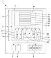
図1は本発明を適用したプリンターの制御系を示す概略ブロック図であり、図2は図1のプリンターの印刷ヘッドおよびメンテナンスユニット、ならびに印刷用紙を模式的に示す説明図である。図1、図2に示すように、プリンター1は、シアンインクC、マゼンタインクM、イエローインクY、ブラックインクBkの4色のインクのインク滴を吐出する印刷ヘッド2と、印刷ヘッド2による印刷位置を経由する搬送経路に沿って印刷用紙P(記録媒体)を搬送する搬送機構3と、メンテナンスユニット4と、印刷ヘッド2、搬送機構3、メンテナンスユニット4等を制御する制御部5と、印刷対象の入力データ(画像データや文書データ等)を受信する通信部6等を備える。本形態では、印刷用紙Pとして、長尺の台紙に一定間隔でラベルが貼り付けられるラベル紙を用いる。ラベル紙の場合、ラベルの全領域あるいはラベル上の所定の領域が印刷領域P1となる。なお、印刷用紙Pとして、ラベルが貼り付けられていない連続用紙や単票紙を用いても良い。
(printer)
FIG. 1 is a schematic block diagram showing a control system of a printer to which the present invention is applied, and FIG. 2 is an explanatory diagram schematically showing a print head, a maintenance unit, and printing paper of the printer of FIG. As shown in FIGS. 1 and 2, the
印刷ヘッド2はライン型のインクジェットヘッドであり、図2に示すように、印刷用紙Pの搬送方向Aに沿って所定の間隔で配列された4組のインクジェットヘッド2C、2M、2Y、2Bkを備える。インクジェットヘッド2C、2M、2Y、2Bkは、いずれも、搬送方向Aと交差する紙幅方向Bの長さが印刷用紙Pの最大幅よりも長く、印刷用紙Pの上にインクを吐出して印刷を行う。印刷用紙Pの搬送方向Aの最上流に配置されたインクジェットヘッド2Bkは黒インクBkを吐出するものであり、その下流側のインクジェットヘッド2CはシアンインクCを吐出するものである。また、インクジェットヘッド2Cの下流側に配置されたインクジェットヘッド2MはマゼンタインクMを吐出するものであり、その下流側のインクジェットヘッド2YはイエローインクYを吐出するものである。
The
インクジェットヘッド2C、2M、2Y、2Bkは、搬送方向Aと交差する紙幅方向Bに配列された4個のヘッドユニット21〜24を備える。4個のヘッドユニット21〜24は、隣り合うヘッドユニットが搬送方向Aに前後するように並んでいる。また、4個のヘッドユニット21〜24は、複数のインクノズル25を紙幅方向Bに所定のノズルピッチで配列したインクノズル列を2列備える。ノズルピッチは、例えば、300dpiに設定される。2列のインクノズル列は、紙幅方向Bの位置を、隣り合うノズル間の距離(ノズルピッチ)の1/2の寸法ずらして配置される。また、紙幅方向Bで隣り合うヘッドユニット21、22は、その端部分のインクノズル25が搬送方向Aに見たときに重なり合うように配置される。同様に、紙幅方向Bに隣り合うヘッドユニット22、23およびヘッドユニット23、24においても、その端部分のインクノズル25が搬送方向Aに見たときに重なり合うように配置される。
The ink jet heads 2C, 2M, 2Y, and 2Bk include four
メンテナンスユニット4は、印刷ヘッド2の待機位置、例えば、搬送経路の幅方向の外側に配置される。印刷ヘッド2は、図示しないヘッド移動機構によって、搬送経路上の印刷用紙Pに対向する位置と、メンテナンスユニット4に対向する位置に移動可能となっている。印刷が行われない待機状態では、メンテナンスユニット4によって、印刷ヘッド2のノズル面がキャッピングされる。また、印刷開始前などの所定のタイミングで、メンテナンスユニット4に対向する位置に印刷ヘッド2を移動させて、メンテナンスユニット4に向けてインクノズル25からインクを吐出する定期フラッシングが実施される。本形態では、後述するように、印刷中に、印刷動作と並行して、印刷領域P1と対向する位置にあるインクノズル25からインク滴を吐出するフラッシング(いわゆる、紙上フラッシング)を実施する。また、定期フラッシングでは、印刷時に使用されないインクノズル25、例えば、印刷領域P1の紙幅方向Bの外側の位置にあるインクノズル25を含むインクノズル25のフラッシングを実施する。従って、印刷領域P1から外れた位置にあるインクノズル25についてもフラッシングを実施でき、その目詰まりを予防あるいは解消できる。
The
(制御系)
プリンター1の制御系は、図1に示すように、CPU等を備える制御部5を中心に構成される。制御部5の入力側には、通信部6が接続される。制御部5には、通信部6を介して、コンピューターなどの外部の機器から、印刷対象の入力データ(画像データや文書データ等)が供給される。一方、制御部5の出力側には、印刷ヘッド2、搬送機構3、メンテナンスユニット4等が接続される。搬送機構3は、印刷用紙Pを搬送する紙送りローラー対、制御部5からの制御信号によって回転する搬送モーター、搬送モーターの回転を紙送りローラー対に伝達する駆動力伝達機構などの公知の機構を備える。
(Control system)
As shown in FIG. 1, the control system of the
制御部5は、記憶部51、レンダリング部52、色変換処理部53、2値化処理部54、フラッシングパターン決定部55、フラッシングパターン合成部56、印刷制御部57、サイズ調整部58、定期フラッシング実行部59等を備える。また、制御部5は、搬送機構3を制御して指定された速度で印刷用紙Pを搬送する搬送制御部(図示省略)を備える。
The
記憶部51は、色変換ルックアップテーブル61、SMLテーブル62、基準フラッシングパターン63、オフセット位置情報テーブル64、フラッシングドット合成テーブル65、サイズ調整テーブル67等を記憶保持する。
The
(印刷モードの設定)
プリンター1の印刷モードは、上述した定期フラッシングを予め設定した基準頻度で行う第1のモードと、基準頻度よりも高頻度で定期フラッシングを行う第2のモードに設定可能である。なお、第2のモードよりも更に高頻度で定期フラッシングを行う第3のモードを設定して、印刷モードを3つ以上設定することもできる。印刷モードの設定と、印刷モードに従って印刷ヘッド2およびメンテナンスユニット4を制御して定期フラッシングを実施する処理は、定期フラッシング実行部59(モード設定部)によって行われる。印刷モードの設定は、制御部5に入力される制御コマンドに基づいて行われる。制御コマンドは、入力データ10に含まれていても良いし、入力データ10と別に供給されるようにしてもよい。
(Print mode setting)
The printing mode of the
(入力データから印刷データへの変換工程)
図3は、入力データからヘッド駆動データへの変換工程を示す説明図である。レンダリング部52は、印刷対象の入力データ10(印刷データ)を、指定された印刷サイズおよび解像度に応じた画素数の画像データ11に変換するレンダリング処理を行う。具体的には、入力データ10を指定された印刷サイズに拡大あるいは縮小し、指定された解像度となるように画素に分解する。レンダリング処理後の画像データ11の画素は、RGB表色系の色データ(RGB多値データ)となっている。
(Conversion process from input data to print data)
FIG. 3 is an explanatory diagram showing a conversion process from input data to head drive data. The
色変換処理部53(印刷ドットパターン生成部の一部)は、色変換ルックアップテーブル61を参照して、レンダリング処理後の画像データ11の各画素(RGB多値データ)をC、Y、M、Bkの4色のインク量データ12(12Bk、12C、12M、12Y)に分解する色変換処理を行う。色変換ルックアップテーブル61には、RGB表色系の色データであるRGB多値データ(R、G、Bの組み合わせ)に対して、C、Y、M、Bkの4色のインク量データが対応付けられる。C、Y、M、Bkのインク量データは、例えば、8ビットの階調値(256階調)で表される。
The color conversion processing unit 53 (a part of the print dot pattern generation unit) refers to the color conversion lookup table 61 and converts each pixel (RGB multi-value data) of the
2値化処理部54(印刷ドットパターン生成部の一部)は、色変換処理後のインク量データ12(12Bk、12C、12M、12Y)について、画素のインク量データを、インクノズル25によって形成可能な4階調のドットデータに変換する処理を行う。SMLテーブル62には、C、M、Y、Bkのインク量データの階調値と、空白ドットを含む4種類のドットの発生率が対応づけられる。4種類のドットは、Null(空白ドット)、S(小ドット)、M(中ドット)、L(大ドット)である。2値化処理部54は、まず、SMLテーブル62を参照して、画素のインク量データを4種類のドットの発生率データに変換するドット割合決定処理を行い、しかる後に、画素におけるドット生成の有無をドットサイズ毎に決定するハーフトーン処理を行う。これにより、インク色毎に、画素の位置に対して空白ドットを含む4種類の印刷ドットのいずれかが指定された印刷ドットパターン13(13Bk、13C、13M、13Y)が生成される。
The binarization processing unit 54 (a part of the print dot pattern generation unit) forms pixel ink amount data with the
サイズ調整部58は、設定された印刷モードに基づき、サイズ調整テーブル67を参照して基準フラッシングパターン63を調整し、調整フラッシングパターン63Bを生成する処理を行う。基準フラッシングパターン63および調整フラッシングパターン63Bの具体的な構成については後述する。
Based on the set print mode, the
フラッシングパターン決定部55は、基準フラッシングパターン63あるいは調整フラッシングパターン63Bと、入力データ10の印刷サイズに基づき、印刷フラッシングパターン66を決定するフラッシングパターン決定処理を行う。印刷フラッシングパターン66は、入力データ10の印刷領域P1への印刷と印刷領域P1上にインク滴を吐出する紙上フラッシングとを行うにあたって、インク滴を吐出するインクノズル25およびそのタイミングを指定するパターンである。印刷フラッシングパターン66の具体的な構成については後述する。
The flushing
フラッシングパターン合成部56は、ハーフトーン処理後の印刷ドットパターン13(13Bk、13C、13M、13Y)と、印刷フラッシングパターン66とを合成するフラッシングパターン合成処理を行う。フラッシングパターン合成処理は、後述するように、オフセット位置情報テーブル64(図8参照)およびフラッシングドット合成テーブル65(図10参照)を参照して行われる。
The flushing
印刷制御部57は、印刷フラッシングパターン66を合成した後の合成ドットパターン14(14Bk、14C、14M、14Y)の各ドットを、インクジェットヘッド2C、2M、2Y、2Bkのインクノズル25に割り当てることで、印刷ヘッド2の駆動に用いるヘッド駆動データ15を生成するヘッド駆動データ生成処理を行う。そして、生成したヘッド駆動データに基づいて印刷ヘッド2からのインクの吐出を制御する。ここで、各色のインクノズル25は、上述したように4個のヘッドユニット21〜24の端部分において搬送方向Aに重複する。このため、ヘッド駆動データ生成処理では、重複する2つのヘッドユニットのどちらか一方のインクノズル25にドットを割り当てるマスク処理が行われる。また、このマスク処理では、搬送方向Aに重複するインクノズル25に割り当てられるドットが、紙上フラッシングのドット(後述するフラッシングドットDf)あるいはこれと印刷ドットを合成したドットである場合には、重複するインクノズル25の両方にドットを割り当てる。
The
(基準フラッシングパターン)
図4は基準フラッシングパターン63の説明図である。この図に示すように、基準フラッシングパターン63は、n列×m行のドットマトリクスパターンであり、空白ドットおよびフラッシングドットDfによって構成されている。図4では、説明を単純にするため、10列×10行のドットマトリクスパターンの例を示しているが、これとは異なる行数および列数のドットマトリクスパターンを用いることもできる。なお、以下の説明において、「列が並ぶ方向」を「列方向」とし、「行が並ぶ方向」を「行方向」とする。すなわち、基準フラッシングパターン63は、列方向にn列が並び、行方向にm行が並ぶドットマトリクスパターンである。
(Reference flushing pattern)
FIG. 4 is an explanatory diagram of the
基準フラッシングパターン63の列方向Vは、インクノズル25の配列方向に対応する。印刷ヘッド2が備える4組のインクジェットヘッド2C、2M、2Y、2Bkは、インクノズル25の紙幅方向Bの配列数が同じであり、紙幅方向Bの列数は、本形態では3200列となる。基準フラッシングパターン63における列方向Vのドット配列数(すなわち、列数n)は、印刷ヘッド2におけるインクノズル25の紙幅方向Bの配列数(3200)よりも少なく設定されている。
The column direction V of the
また、基準フラッシングパターン63の行方向Hは、フラッシングの実施タイミングに対応する。基準フラッシングパターン63の行方向Hのサイズ(すなわち、行数m)は、フラッシングの実施周期(すなわち、フラッシングドットDfの発生周期)をドット数に置き換えたものである。例えば、0.1secに1回フラッシングを実施する場合、この期間(0.1sec)に印刷されるドット数(すなわち、行数m)は、印刷速度や解像度の設定にもよるが、1000〜10000ドットの範囲内の数となる。例えば、フラッシングドットDfの発生周期が5000ドットの場合、行数mは5000に設定される。なお、行数mをフラッシングドットDfの発生周期の整数倍にしても良いが、基準フラッシングパターン63のサイズを小さくするため、行数m=フラッシングドットDfの発生周期とする。
The row direction H of the
ここで、解像度が一定の場合に、印刷速度が遅くなると、1周期のドット数が少なくな
る。また、印刷速度が一定で、解像度が変化する場合も、1周期のドット数が少なくなる
。印刷速度は、単位時間に印刷される寸法(搬送方向Aの長さ)であり、例えば、300
mm/secなどの値が適用される。基準フラッシングパターン63の行方向Hのサイズ
はフラッシング発生周期のドット数であるため、印刷速度および解像度に比例して増減さ
れる。すなわち、印刷速度が遅い場合に、基準フラッシングパターン63の行方向Hのサ
イズを小さくできる。また、解像度が低い場合に、基準フラッシングパターン63の行方
向Hのサイズを小さくできる。
Here, when the resolution is constant and the printing speed is slow, the number of dots in one cycle decreases. Also, when the printing speed is constant and the resolution changes, the number of dots in one cycle is reduced. The printing speed is a dimension printed in a unit time (length in the conveyance direction A), for example, 300
A value such as mm / sec is applied. Since the size of the
基準フラッシングパターン63は、1周期のフラッシングパターンであるため、1列に1つのフラッシングドットDfを含む。各列のフラッシングドットDfの位置によってフラッシングの実施タイミングが指定される。フラッシングドットDfの位置は、n列のうちの一部では一致しており、他の列では互いに異なる。例えば、図4の例では、基準フラッシングパターン63の3列目と10列目では1行目にフラッシングドットDfが配置される。一方、他の8つの列では、フラッシングドットDfの位置は異なる行(2〜7行、9〜10行の8つの行)に分散する。なお、n列のうちの3列以上でフラッシングドットDfを同じ行に配置してもよい。
Since the
(印刷モードが異なる場合の基準フラッシングパターン63のサイズ調整)
図5は調整フラッシングパターン63Bおよびその生成方法の説明図である。サイズ調整部58は、設定された印刷モードが第1のモード、すなわち、基準頻度で定期フラッシングを行うモードのとき、調整フラッシングパターン63Bを生成する処理を行わない。一方、設定された印刷モードが第2のモード、すなわち、基準頻度よりも高頻度の所定のモードで定期フラッシングを行うモードのとき、図5に示すように、基準フラッシングパターン63に空白行を付加してフラッシングドットDfの行方向Hの発生頻度を減らした調整フラッシングパターン63Bを生成する。調整フラッシングパターン63Bの列には、基準フラッシングパターン63の列と同様に、1列に1つのフラッシングドットDfが含まれる。
(Adjusting the size of the
FIG. 5 is an explanatory diagram of the
ここで、サイズ調整テーブル67には、印刷モードのそれぞれに対して、適正なフラッシングドットDfの発生頻度を示す値が対応付けられる。例えば、図5に示す例の場合、第1のモードに対しては、10(10行につき1ドット)を対応付ける。また、第2のモードに対しては、25(25行につき1ドット)を対応付けたサイズ調整テーブル67を作成する。上述したように、第2のモードは、定期フラッシングを基準頻度より高頻度で行うものであるため、紙上フラッシングにおけるインクノズル25のフラッシングの実施間隔を基準頻度のときよりも長くすることができる。このため、第2のモードでは、フラッシングドットDfの行方向Hの発生頻度が低頻度に設定される。
Here, in the size adjustment table 67, a value indicating the occurrence frequency of the appropriate flushing dot Df is associated with each print mode. For example, in the example shown in FIG. 5, 10 (1 dot per 10 rows) is associated with the first mode. In addition, for the second mode, a size adjustment table 67 in which 25 (1 dot per 25 rows) is associated is created. As described above, in the second mode, the regular flushing is performed at a frequency higher than the reference frequency. Therefore, the flushing interval of the
サイズ調整部58は、サイズ調整テーブル67を参照して、設定された印刷モードに対応づけられたフラッシングドットDfの発生頻度を実現するサイズ調整比率Qを算出する。具体的には、第1の値(10)を第2の値(25)に調整する基準フラッシングパターン63のサイズ調整比率Qとして、Q=2.5(=25/10)を算出する。なお、各印刷モードに対応するサイズ調整比率Qを予め算出しておき、この値を印刷モードに定めたテーブルをサイズ調整テーブル67として用いても良い。サイズ調整部58は、サイズ調整比率Qを算出すると、基準フラッシングパターン63を行方向HにQ倍に比例拡大して、調整フラッシングパターン63Bを生成する。調整フラッシングパターン63Bの行方向Hのサイズである行数は、サイズ調整比率Qに基づき、m×Qで決定される。すなわち、m=10、Q=2.5の場合、m×Q=25となる。m×Qが小数点以下の端数を含む場合、端数を切り捨てた行数とする。
The
調整フラッシングパターン63Bの各列には、1列に1つのフラッシングドットDfが含まれる。調整フラッシングパターン63Bの列におけるフラッシングドットDfの位置は、基準フラッシングパターン63を行方向HにQ倍に比例拡大パターンであり、各列におけるフラッシングドットDfの位置は、行方向HにQ倍に比例拡大した位置に決定される。すなわち、元の基準フラッシングパターン63におけるフラッシングドットDfの座標が(g、h(gは行番号すなわち行方向Hの座標、hは列番号すなわち列方向Vの座標))であるとき、g×Qを算出して、この値に基づいて調整フラッシングパターン63BにおけるフラッシングドットDfの位置を決定する。具体的には、g×Qから小数点以下の端数を切り捨てた値g1を算出する。そして、座標(g1、h)を調整フラッシングパターン63BにおけるフラッシングドットDfの位置に決定する。フラッシングドットDfについてこのように座標を算出することで、調整フラッシングパターン63BにおけるフラッシングドットDfの配置が決定される。そして、このような配置を実現するように基準フラッシングパターン63に空白行を付加することで、調整フラッシングパターン63Bが生成される。
Each row of the
図5には、サイズ調整処理における行番号g(行方向Hの座標)の変換例を示している。g×Qから小数点以下の端数を切り捨てる処理によって、元の基準フラッシングパターン63の行番号g(具体的には、1、2・・・10)が、g1(具体的には、2、5、7、10、12、15、17、20、22、25)に変換される。そして、フラッシングドットDfを変換後の行に移動させ、空白行として、1、3、4、6、8、9、11、13、14、16、18、29、21、23、24行の15行を追加する。
FIG. 5 shows a conversion example of the line number g (coordinate in the row direction H) in the size adjustment process. By the process of rounding off fractions from g × Q, the line number g (specifically, 1, 2,..., 10) of the original
なお、図5の例は、先頭行を1行目として行番号を設定してサイズ調整処理を行った例であるが、先頭行の行番号を0行目として行番号g1を算出してサイズ調整処理を行ってもよい。この方法でも、フラッシングドットDfを行方向Hに比例拡大した位置に移動させることができる。また、サイズ調整比率Qを2.5と異なる値にした場合にも、同様にフラッシングドットDfの発生頻度を調整できる。なお、本形態では、g×Qから小数点以下の端数を切り捨ててg1を算出しているが、小数点以下の端数を切り上げる方法、あるいは、四捨五入する方法でg1を算出してサイズ調整を行っても良い。 The example of FIG. 5 is an example in which the line number is set and the size adjustment process is performed with the first line as the first line. However, the line number g1 is calculated with the line number of the first line as the 0th line and the size is calculated. Adjustment processing may be performed. Even in this method, the flushing dot Df can be moved to a position proportionally enlarged in the row direction H. Further, even when the size adjustment ratio Q is set to a value different from 2.5, the occurrence frequency of the flushing dot Df can be similarly adjusted. In this embodiment, g1 is calculated by rounding off the fractional part from g × Q. However, the size may be adjusted by calculating g1 by rounding up the fractional part or rounding off. good.
(印刷フラッシングパターン)
図6は印刷フラッシングパターン66の説明図であり、印刷用紙Pに所定ピッチで配列された複数の印刷領域P1に複数の入力データ10を続けて印刷する場合に用いる複数の印刷フラッシングパターン66の例を示している。また、図6の例は、基準頻度で定期フラッシングを行う第1のモードであって、基準フラッシングパターン63から印刷フラッシングパターン66を生成する場合の例である。図6に示すように、印刷用紙Pには、隣り合う印刷領域P1の間に非印刷領域が配置される。第1の印刷領域P1(1)には第1の入力データ10(1)を印刷し、続いて、第2の印刷領域P1(2)には第2の入力データ10(2)を印刷する。3以上の入力データ10を続けて印刷する場合には、同様に、i番目(i≧3)の印刷領域P1(i)まで入力データ10(i)を続けて印刷する。
(Print flushing pattern)
FIG. 6 is an explanatory diagram of a
このとき、フラッシングパターン決定部55によって、入力データ10((1)、10(2)・・・10(i))に対して、その印刷サイズに対応するサイズの印刷フラッシングパターン66(66(1)、66(2)・・・66(i))が形成される。すなわち、第1の入力データ10(1)の印刷サイズと同一サイズの第1の印刷フラッシングパターン66(1)、第2の入力データ10(2)の印刷サイズと同一サイズの第2の印刷フラッシングパターン66(2)が生成される。同様に、i番目の入力データ10(i)の印刷サイズと同一サイズの印刷フラッシングパターン66(i)が生成される。印刷フラッシングパターン66(66(1)、66(2)・・・66(i))は、後述する合成処理によって、入力データ10(10(1)、10(2)・・・10(i))から生成された印刷ドットパターン13(13(1)、13(2)・・・13(i))と合成される。
At this time, the flushing
入力データ10(10(1)、10(2)・・・10(i))の印刷サイズは、上述したレンダリング処理後の画像データ11のサイズであり、より具体的には、画素を印刷ドットに置き換えた印刷ドットパターン13のサイズである。印刷モードが第1のモードのとき、印刷フラッシングパターン66(66(1)、66(2)・・・66(i))は、基準フラッシングパターン63の行方向Hを搬送方向Aと一致させ、列方向Vを搬送方向Aと交差する紙幅方向Bと一致させる向きに配置して、この基準フラッシングパターン63を行方向Hおよび列方向Vに繰り返し配列して生成される。例えば、印刷フラッシングパターン66(1)には、基準フラッシングパターン63が行方向Hおよび列方向Vに複数回繰り返して配列されている。このような方法で、1周期分のフラッシングパターンである基準フラッシングパターン63から、任意の印刷サイズと同じサイズの印刷フラッシングパターン66を生成する。ここで、印刷モードが第1モードと異なる第2モードのときは、調整フラッシングパターン63Bが生成される。この場合には、フラッシングパターン決定部55は、基準フラッシングパターン63に代えて調整フラッシングパターン63Bを用いて、同様に印刷フラッシングパターン66を生成する。
The print size of the input data 10 (10 (1), 10 (2)... 10 (i)) is the size of the
図6に示す例では、第1の印刷フラッシングパターン66(1)の先頭行は、基準フラッシングパターン63の1行目のドット列である。一方、第1の印刷フラッシングパターン66(1)の最終行は、基準フラッシングパターン63のk行目(k<m)のドット列である。このように、第1の入力データ10(1)の搬送方向Aの印刷サイズが基準フラッシングパターン63の行方向Hのサイズの整数倍でない場合、第1の印刷フラッシングパターン66(1)の最終行(k行)は、基準フラッシングパターン63の最終行(m行)とは異なるドット列になる。
In the example illustrated in FIG. 6, the first row of the first print flushing pattern 66 (1) is the first dot row of the
フラッシングパターン決定部55は、基準フラッシングパターン63の途中、すなわち、m行目よりも前の行で第1の印刷フラッシングパターン66(1)が終わる場合には、次の印刷で使用される第2の印刷フラッシングパターン66(2)の先頭行を、直前に用いられた第1の印刷フラッシングパターン66(1)の最終行に基づいて決定する。具体的には、第2の印刷フラッシングパターン66(2)の先頭行を、第1の印刷フラッシングパターン66(1)の最終行(k行)の次の行(k+1行)にする。同様に、i番目の印刷フラッシングパターン66(i)の先頭行を、直前の印刷フラッシングパターン66(i−1)の最終行であるj行(j<m)の次の行(j+1行)とする。
When the first printing flushing pattern 66 (1) ends in the middle of the
このように、連続印刷の場合には、直前の印刷フラッシングパターン66の最終行に基づいて基準フラッシングパターン63の位置をオフセットして配列して、次の印刷フラッシングパターン66を生成する。その結果、連続して使用される2つの印刷フラッシングパターン66にわたって、基準フラッシングパターン63で定めたフラッシングの頻度が保たれるようにフラッシングドットDfが配列されることになる。これにより、複数の印刷領域P1への連続印刷の全工程において、基準フラッシングパターン63で定めたフラッシングの頻度が保たれるように、フラッシングドットDfの配列が決定される。
Thus, in the case of continuous printing, the position of the
また、基準フラッシングパターン63に代えて調整フラッシングパターン63Bを行方向Hおよび列方向Vに配列して印刷フラッシングパターン66を決定する場合においても、同様に、印刷フラッシングパターン66の先頭行を直前の印刷フラッシングパターン66の最終行を考慮して決定することで、調整フラッシングパターン63Bで定めたフラッシングドットDfの発生頻度を保つようにする。これにより、各印刷モードにおいて最適な頻度を保つようにフラッシングドットDfを発生させることができる。
Similarly, when the
(印刷フラッシングパターンの合成)
図7は、印刷フラッシングパターン66と印刷ドットパターン13(13Bk、13C、13M、13Y)をインク色別にオフセットして重ね合わせた状況を示す説明図である。また、図8はオフセット位置情報テーブル64の説明図である。図8に示すように、オフセット位置情報テーブル64には、C、Y、M、Bkの4つのインク色について、行方向Hのオフセット量Dhおよび列方向Vのオフセット量Dvの組み合わせである色別オフセット量(Dh、Dv)が対応づけられる。色別オフセット量(Dh、Dv)の値は、例えば、Bk、C、M、Yの順に、(0、0)、(4、1)、(6、3)、(5、5)のように設定される。なお、色別オフセット量は、DhとDvの一方あるいは両方が互いに異なっていればよく、図8に示す値に限定されるものではない。
(Composition of printing flushing pattern)
FIG. 7 is an explanatory diagram illustrating a state in which the
印刷フラッシングパターン66と印刷ドットパターン13(13Bk、13C、13M、13Y)との合成処理では、まず、4つの印刷ドットパターン13(13Bk、13C、13M、13Y)に対して、同一の印刷フラッシングパターン66を、指定された色別オフセット量(Dh、Dv)だけずらして重ね合わせる。具体的には、図7(a)に示すように、印刷ドットパターン13Bkには、色別オフセット量(0、0)に基づき、印刷フラッシングパターン66がオフセットなしで重ね合わされる。同様に、図7(b)に示すように、印刷ドットパターン13Cには、色別オフセット量(4、1)に基づき、印刷フラッシングパターン66が行方向Hに4ドット、列方向Vに1ドットずらして重ね合わされる。また、図7(c)に示すように、印刷ドットパターン13Mには、色別オフセット量(6、3)に基づき、印刷フラッシングパターン66が行方向Hに6ドット、列方向Vに3ドットずらして重ね合わされる。そして、図8(d)に示すように、印刷ドットパターン13Yには、色別オフセット量(5、5)に基づき、印刷フラッシングパターン66が行方向Hに5ドット、列方向Vに5ドットずらして重ね合わされる。
In the synthesis process of the
図7(e)に示すように、印刷フラッシングパターン66は、インク色によってオフセット位置をずらして重ね合わせられ、印刷ドットパターン13(13Bk、13C、13M、13Y)と合成される。すなわち、印刷ドットパターン13Bkと印刷フラッシングパターン66が黒インクに対するオフセット量(0、0)に基づいて合成され、印刷ドットパターン13Cと印刷フラッシングパターン66がシアンインクに対するオフセット量(4、1)に基づいて合成され、印刷ドットパターン13Mと印刷フラッシングパターン66がマゼンダインクに対するオフセット量(6、3)に基づいて合成され、印刷ドットパターン13Yと印刷フラッシングパターン66がイエローインクに対するオフセット量(5、5)に基づいて合成される。このように、インク色によってオフセット位置をずらすことで、フラッシングドットDfの位置が複数のインク色について重なり合うことを回避できる。これにより、紙上フラッシングの実施による印刷結果の変化(すなわち、フラッシングによるドットの追加や、ドットサイズの変更)を目立たないようにすることができる。従って、印刷領域にフラッシングを実施したことによる印刷品質の低下を抑制できる。また、オフセット位置をずらすことで、複数のインク色のインクを吐出する複数のインクノズルに対して、同一の印刷フラッシングパターン66を用いることができる。従って、処理負担を小さくでき、記憶容量も少なくて済む。
As shown in FIG. 7E, the
図9は印刷フラッシングパターン66と印刷ドットパターン13(13Bk、13C、13M、13Y)の合成方法の説明図であり、フラッシングドットDfが重ね合わされた位置でのドットサイズの変化を示している。また、図10はフラッシングドット合成テーブル65の説明図である。フラッシングドット合成テーブル65には、印刷ドットにおける4階調のドットサイズのそれぞれについて、フラッシングドットDfが重なった場合に最終的に採用する最終ドットサイズ(すなわち、補正後のドットサイズ)が対応付けられている。図9、図10は、フラッシングドットDfのドットサイズをMに設定した場合について例示している。
FIG. 9 is an explanatory diagram of a method for synthesizing the
フラッシングドット合成テーブル65は、印刷ドットにフラッシングドットDfが重なったときは、ドットサイズの大きい方を最終的なドットサイズとして用いるように設定される。具体的には、図10に示すように、Mより小さいサイズの印刷ドットD(Null)、D(S)にフラッシングドットDfが重なったときは、ドットサイズをMドットに変換して、最終ドットDt(M)を用いる。一方、MまたはLサイズの印刷ドットD(M)、D(L)にフラッシングドットDfが重なったときは、元の印刷ドットのドットサイズを適用して、最終ドットDt(M)あるいはDt(L)を用いる。フラッシングドット合成テーブル65を参照することで、図9に示すように、印刷フラッシングパターン66を重ね合わされた印刷ドットパターン13(13Bk、13C、13M、13Y)から合成ドットパターン14(14Bk、14C、14M、14Y)が生成される。このように、異なるサイズのドットが重なったときはサイズすなわちインクの吐出量が多いドットを用いることで、ノズル面近傍のインクの粘度の増大を抑制できる。また、このような合成方法では、単にフラッシングドットDfを追加する方法と比較して、フラッシングドットDfの合成に伴う印刷対象データの変化を最小限にすることができる。
The flushing dot composition table 65 is set to use the larger dot size as the final dot size when the flushing dot Df overlaps the print dot. Specifically, as shown in FIG. 10, when the flushing dot Df overlaps the printing dots D (Null) and D (S) of a size smaller than M, the dot size is converted to M dots, and the final dot Dt (M) is used. On the other hand, when the flushing dot Df overlaps the M or L size print dots D (M) and D (L), the dot size of the original print dot is applied to obtain the final dot Dt (M) or Dt (L ) Is used. By referring to the flushing dot composition table 65, as shown in FIG. 9, the composite dot pattern 14 (14Bk, 14C, 14M) is generated from the print dot pattern 13 (13Bk, 13C, 13M, 13Y) on which the
(印刷方法)
プリンター1の制御部5は、画像データや文書データなどの入力データ10(印刷データ)を、通信部6を介して受け取ると、この入力データ10に対して上述したレンダリング処理、色変換処理、2値化処理(ドット割合決定処理およびハーフトーン処理)を行い、上述した印刷フラッシングパターン66の決定処理および印刷ドットパターン13(13Bk、13C、13M、13Y)との合成処理を行って、合成ドットパターン14に基づいてヘッド駆動データ15を生成する。
(Printing method)
When the
その一方で、制御部5は、印刷用紙Pを印刷ヘッド2に向けて搬送し、印刷ヘッド2による印刷位置に印刷用紙Pの印刷領域P1の先頭部分を位置決めする頭出し動作を行う。そして、頭出し動作が完了すると、生成したヘッド駆動データ15に基づいて、各インクノズル25に対応する圧電素子に印加される電圧のパルスを駆動信号として生成して、印刷ヘッド2に供給する。これにより、印刷ヘッド2が駆動され、インクジェットヘッド2C、2M、2Y、2Bkの各インクノズル25からインク滴が吐出されて、入力データ10で指示された内容の印刷が行われる。制御部5は、ヘッド駆動データ15に基づいて印刷ヘッド2を駆動して印刷用紙Pにインクを吐出する動作と、ヘッド駆動データ15において指定された印刷解像度に対応する搬送量だけ印刷用紙Pを搬送する動作を行う。また、印刷を開始する直前やその前の待機中、印刷を終了した後の待機中などの期間に、設定された印刷モードに従い、基準頻度あるいはこれと異なる所定の頻度で、定期フラッシングを実施する。
On the other hand, the
ヘッド駆動データ15には印刷フラッシングパターン66が合成されているので、ヘッド駆動データ15に従って印刷ヘッド2を駆動することで、入力データ10の印刷を目的とするインクドットの形成動作と、インクノズル25のフラッシングを目的とするインクドットの形成動作が行われる。すなわち、印刷領域P1への画像や文書等の印刷と、印刷領域P1上へのフラッシング(紙上フラッシング)が行われる。紙上フラッシングによるインクノズル25からのインク滴の吐出頻度は、定期フラッシングの実施周期に応じて調整されている。
Since the
以上のように、本形態のプリンター1では、入力データ10の印刷領域P1への印刷動作と、紙上フラッシングとを行う。従って、印刷時のスループットを低下させることなく、インクノズル25の目詰まりを予防あるいは解消でき、印刷品質の低下を抑制できる。特に、本形態では、フラッシングの1周期のサイズの基準フラッシングパターン63を用いて任意の印刷サイズに相当するサイズの印刷フラッシングパターン66を生成できる。従って、小さなサイズの基準フラッシングパターン63から簡単な処理で印刷フラッシングパターン66を生成できる。このため、紙上フラッシングの実施に必要なデータの記憶容量が少なく、画像処理の負荷も小さい。
As described above, the
また、本形態では、紙上フラッシングとは別に、メンテナンスユニット4にインクを吐出する定期フラッシングを行っている。従って、印刷領域外のインクノズル25が使用されずに印刷が行われる場合においても、定期フラッシングによってインクノズル25の目詰まりを予防あるいは解消できる。そして、定期フラッシングの実施頻度を基準頻度とする第1のモードで印刷するときは基準フラッシングパターン63をそのまま用いるが、基準頻度よりも高頻度で定期フラッシングを行う第2のモードで印刷することも可能であり、このときは、サイズ調整比率Qに基づいて基準フラッシングパターン63(第1のフラッシングパターン)を行方向Hに比例拡大するサイズ調整を行って、調整フラッシングパターン63B(第2のフラッシングパターン)を生成する。そして、基準フラッシングパターン63に代えて調整フラッシングパターン63Bを用いて印刷フラッシングパターン66を生成する。このようにすると、定期フラッシングの実施頻度が異なる複数の印刷モードにおいて、最適なインク滴の吐出頻度で紙上フラッシングを行うことができる。また、このような頻度調整を行う構成でありながら、複数のフラッシングパターンを記憶しておく必要がない。従って、紙上フラッシングの実施に必要なデータの記憶容量を小さくすることができる。
In the present embodiment, regular flushing for discharging ink to the
更に、本形態では、最も低頻度で定期フラッシングを行う第1のモードで用いられる1周期分のフラッシングドットDfの配置パターンを基準フラッシングパターン63としている。従って、基準フラッシングパターン63のサイズを最も小さくすることができ、紙上フラッシングの実施に必要なデータの記憶容量を小さくすることができる。なお、基準頻度よりも更に低頻度で定期フラッシングを行うモードを設定し、基準フラッシングパターン63を比例縮小することによって調整フラッシングパターン63Bを生成することも可能である。しかしながら、この場合には、基準フラッシングパターン63が最小のサイズにならない。従って、最も低頻度で定期フラッシングを行うモードで用いるパターンを基準フラッシングパターン63に設定することが望ましい。
Furthermore, in this embodiment, the arrangement pattern of the flushing dots Df for one cycle used in the first mode in which the regular flushing is performed at the lowest frequency is used as the
(他の形態)
(1)上記形態では、インクノズル25毎のインク滴の吐出頻度を変えるために、基準フラッシングパターン63を行方向Hに比例拡大あるいは比例縮小するサイズ調整を行っているが、異なる印刷速度で印刷を行うときは、インクノズル25毎のインク滴の吐出頻度が一定であっても、基準フラッシングパターン63の列方向のサイズが変化する。そこで、印刷速度を基準印刷速度Fと異なる印刷速度F1にして印刷を行う場合には、印刷速度および印刷モードに基づいてサイズ調整比率Qを決定し、基準フラッシングパターン63のサイズ調整を行うことが望ましい。この場合には、印刷モードに基づいて上記形態のようにサイズ調整比率Q1を決定し、印刷速度に基づいて速度比Q2(Q2=F1/F)を設定し、最終比率Q=Q1×Q2とすればよい。
(Other forms)
(1) In the above embodiment, in order to change the ejection frequency of ink droplets for each
(2)上記形態は、基準頻度で定期フラッシングを行うときに用いる基準フラッシングパターン63を基準として、印刷モードすなわち定期フラッシングの頻度に応じて紙上フラッシングにおけるインクノズル25のインク滴の吐出頻度を調整するものであったが、解像度や、環境条件(例えば、気温や湿度)などの他のパラメーターに応じて、同様にインクノズル25のインク滴の吐出頻度を調整する処理を行ってもよい。また、気温や湿度および印刷モードを含む複数のパラメーターの組み合わせに基づいて調整フラッシングパターンを生成してもよい。
(2) The above embodiment adjusts the ejection frequency of the ink droplets of the
1…プリンター(印刷装置)、2…印刷ヘッド、2Bk、2C、2M、2Y…インクジェットヘッド、3…搬送機構、4…メンテナンスユニット、5…制御部、6…通信部、10…入力データ(印刷データ)、11…画像データ、12(12Bk、12C、12M、12Y)…インク量データ、13(13Bk、13C、13M、13Y)…印刷ドットパターン、14(14Bk、14C、14M、14Y)…合成ドットパターン、15…印刷データ、21〜24…ヘッドユニット、25…インクノズル、51…記憶部、52…レンダリング部、53…色変換処理部(印刷ドットパターン生成部の一部)、54…2値化処理部(印刷ドットパターン生成部の一部)、55…フラッシングパターン決定部、56…フラッシングパターン合成部、57…印刷制御部、58…サイズ調整部、59…定期フラッシング実行部(モード設定部)、61…色変換ルックアップテーブル、62…SMLテーブル、63…基準フラッシングパターン(第1のフラッシングパターン)、63B…調整フラッシングパターン(第2のフラッシングパターン)、64…オフセット位置情報テーブル、65…フラッシングドット合成テーブル、66…印刷フラッシングパターン、67…サイズ調整テーブル、A…搬送方向、B…紙幅方向、D…印刷ドット、Df…フラッシングドット、Dt…最終ドット、H…行方向、V…列方向、P…印刷用紙(記録媒体)、P1…印刷領域、Q…サイズ調整比率
DESCRIPTION OF
Claims (8)
る第1のモードで印刷を行うときには、
フラッシングドットを含むn列×m行(n、mはいずれも2以上の整数)の第1のフラ
ッシングパターンを記録媒体の搬送方向と交差する列方向および前記搬送方向である行方
向に配列して、第1の印刷フラッシングパターンを生成し、
前記フラッシングの頻度を前記第1の頻度と異なる第2の頻度とする第2のモードで印
刷を行うときには、
前記第1のフラッシングパターンの行数を前記第2の頻度に対応する行数に増減した第
2のフラッシングパターンを生成し、前記第2のフラッシングパターンを前記列方向およ
び前記行方向に配列して、第2の印刷フラッシングパターンを生成し、
印刷データに基づいて印刷ドットパターンを生成し、
前記印刷ドットパターンと、前記第1の印刷フラッシングパターン、もしくは前記第2の印刷フラッシングパターンとをフラッシングドット合成テーブルに基づいて合成した合成ドットパターンを生成し、
前記合成ドットパターンに基づいて、前記インクを印刷ヘッドから前記記録媒体に吐出することを特徴とする印刷方法。 When performing printing in the first mode in which the frequency of flushing for discharging ink toward the maintenance unit is set to the first frequency,
A first flushing pattern of n columns × m rows (n and m are integers of 2 or more) including flushing dots is arranged in a column direction intersecting with the conveyance direction of the recording medium and a row direction that is the conveyance direction. Generate a first print flushing pattern;
When performing printing in the second mode in which the flushing frequency is set to a second frequency different from the first frequency,
A second flushing pattern is generated by increasing or decreasing the number of rows of the first flushing pattern to the number of rows corresponding to the second frequency, and the second flushing pattern is arranged in the column direction and the row direction. Generate a second print flushing pattern ;
Generate a print dot pattern based on the print data,
Generating a composite dot pattern in which the print dot pattern and the first print flushing pattern or the second print flushing pattern are synthesized based on a flushing dot synthesis table;
A printing method , wherein the ink is ejected from a print head onto the recording medium based on the synthetic dot pattern .
い請求項1に記載の印刷方法。 The printing method according to claim 1, wherein the first frequency in the first mode is smaller than the second frequency in the second mode.
ンより行数の多い前記第2のフラッシングパターンを生成する請求項2に記載の印刷方法
。 The printing method according to claim 2, wherein a blank line is added to the first flushing pattern to generate the second flushing pattern having a larger number of lines than the first flushing pattern.
1ないし3のいずれか1項に記載の印刷方法。 The printing method according to claim 1, wherein the first flushing pattern includes one flushing dot in one row.
記録媒体を搬送する搬送機構と、
前記印刷ヘッドの前記インクノズルから吐出されたインクを受けるメンテナンスユニッ
トと、
前記印刷ヘッドによる印刷のモードを、前記メンテナンスユニットにインクを吐出する
フラッシングを第1の頻度で実行する第1のモード、もしくは、前記第1の頻度と異なる
第2の頻度で前記フラッシングを実行する第2のモードに設定するモード設定部と、
フラッシングドットを含むn列×m行(n、mはいずれも2以上の整数)の第1のフラ
ッシングパターンとフラッシングドット合成テーブルを記憶する記憶部と、
印刷データに基づいて印刷ドットパターンを生成する印刷ドットパターン生成部と、
前記第1のモードでは、前記第1のフラッシングパターンを前記記録媒体の搬送方向と
交差する列方向および前記搬送方向である行方向に配列して第1の印刷フラッシングパタ
ーンを生成し、前記第2のモードでは、前記第1のフラッシングパターンの行数を前記第
2の頻度に対応する行数に増減した第2のフラッシングパターンを生成して、前記第2の
フラッシングパターンを前記列方向および前記行方向に配列して第2の印刷フラッシング
パターンを生成するフラッシングパターン決定部と、
前記印刷ドットパターンと、前記第1の印刷フラッシングパターンもしくは前記第2の
印刷フラッシングパターンとをフラッシングドット合成テーブルに基づいて合成するフラッシングパターン合成部と、
前記フラッシングパターン合成部で生成されたデータに基づいて前記印刷ヘッドからイ
ンクを吐出させる印刷制御部と、
を有することを特徴とする印刷装置。 A print head comprising ink nozzles;
A transport mechanism for transporting the recording medium;
A maintenance unit for receiving ink ejected from the ink nozzles of the print head;
The printing mode by the print head is performed in a first mode in which flushing for discharging ink to the maintenance unit is performed at a first frequency, or the flushing is performed in a second frequency different from the first frequency. A mode setting unit for setting the second mode;
A storage unit for storing a first flushing pattern and a flushing dot composition table of n columns × m rows (n and m are integers of 2 or more) each including a flushing dot ;
A print dot pattern generation unit that generates a print dot pattern based on the print data;
In the first mode, the first flushing pattern is arranged in a column direction intersecting with a conveyance direction of the recording medium and a row direction which is the conveyance direction to generate a first print flushing pattern, and the second In this mode, a second flushing pattern in which the number of rows of the first flushing pattern is increased or decreased to the number of rows corresponding to the second frequency is generated, and the second flushing pattern is changed to the column direction and the row. A flushing pattern determination unit that generates a second print flushing pattern arranged in a direction;
A flushing pattern synthesis unit that synthesizes the print dot pattern and the first print flushing pattern or the second print flushing pattern based on a flushing dot synthesis table ;
A print control unit that ejects ink from the print head based on the data generated by the flushing pattern synthesis unit;
A printing apparatus comprising:
い請求項5に記載の印刷装置。 The printing apparatus according to claim 5, wherein the first frequency in the first mode is smaller than the second frequency in the second mode.
して、前記第1のフラッシングパターンより行数の多い前記第2のフラッシングパターン
を生成する請求項6に記載の印刷装置。 The printing apparatus according to claim 6, wherein the flushing pattern determination unit generates the second flushing pattern having a larger number of lines than the first flushing pattern by adding blank lines to the first flushing pattern.
5ないし7のいずれか1項に記載の印刷装置。 The printing apparatus according to claim 5, wherein the first flushing pattern includes one flushing dot in one row.
Priority Applications (1)
| Application Number | Priority Date | Filing Date | Title |
|---|---|---|---|
| JP2013260962A JP6237197B2 (en) | 2013-12-18 | 2013-12-18 | Printing method and printing apparatus |
Applications Claiming Priority (1)
| Application Number | Priority Date | Filing Date | Title |
|---|---|---|---|
| JP2013260962A JP6237197B2 (en) | 2013-12-18 | 2013-12-18 | Printing method and printing apparatus |
Publications (3)
| Publication Number | Publication Date |
|---|---|
| JP2015116719A JP2015116719A (en) | 2015-06-25 |
| JP2015116719A5 JP2015116719A5 (en) | 2016-05-26 |
| JP6237197B2 true JP6237197B2 (en) | 2017-11-29 |
Family
ID=53529917
Family Applications (1)
| Application Number | Title | Priority Date | Filing Date |
|---|---|---|---|
| JP2013260962A Active JP6237197B2 (en) | 2013-12-18 | 2013-12-18 | Printing method and printing apparatus |
Country Status (1)
| Country | Link |
|---|---|
| JP (1) | JP6237197B2 (en) |
Families Citing this family (1)
| Publication number | Priority date | Publication date | Assignee | Title |
|---|---|---|---|---|
| US11667120B2 (en) | 2019-12-27 | 2023-06-06 | Ricoh Company, Ltd. | Liquid discharge apparatus |
Family Cites Families (4)
| Publication number | Priority date | Publication date | Assignee | Title |
|---|---|---|---|---|
| JP2006001051A (en) * | 2004-06-15 | 2006-01-05 | Canon Inc | Inkjet recording method and inkjet recorder |
| JP4720924B2 (en) * | 2009-03-24 | 2011-07-13 | ブラザー工業株式会社 | Recording device |
| JP4992928B2 (en) * | 2009-03-31 | 2012-08-08 | ブラザー工業株式会社 | Recording device |
| JP5969029B2 (en) * | 2011-08-26 | 2016-08-10 | オセ−テクノロジーズ ビーブイ | Inkjet printing method and printer |
-
2013
- 2013-12-18 JP JP2013260962A patent/JP6237197B2/en active Active
Also Published As
| Publication number | Publication date |
|---|---|
| JP2015116719A (en) | 2015-06-25 |
Similar Documents
| Publication | Publication Date | Title |
|---|---|---|
| JP6347116B2 (en) | Printing apparatus and printing method | |
| JP5211838B2 (en) | Correction value calculation method and liquid ejection method | |
| US8684490B2 (en) | Image forming apparatus, method of processing image, and computer-readable recording medium | |
| JP5125666B2 (en) | Liquid ejection device | |
| JP6095398B2 (en) | Recording apparatus and recording method | |
| JPH07232434A (en) | Method and device for recording | |
| JP5776348B2 (en) | Image forming apparatus and image forming method | |
| JP2011255594A (en) | Liquid ejection device and liquid ejection method | |
| JP2016147421A (en) | Printing control device and printing control method | |
| JP6054850B2 (en) | Recording apparatus and recording method | |
| JP6237197B2 (en) | Printing method and printing apparatus | |
| JP6237195B2 (en) | Printing method and printing apparatus | |
| JP6218531B2 (en) | Line-type inkjet recording device | |
| JP6240438B2 (en) | Inkjet recording device | |
| EP3225406B1 (en) | Liquid droplet discharging control device, liquid droplet discharging control method, and liquid droplet discharging apparatus | |
| JP2018001765A (en) | Printing method and printer | |
| JP7380040B2 (en) | inkjet recording device | |
| JP6171916B2 (en) | Printing method and printing apparatus | |
| JP6237196B2 (en) | Printing method and printing apparatus | |
| JP6171915B2 (en) | Printing method and printing apparatus | |
| JP2010064371A (en) | Method of correction and liquid ejection device | |
| US11386311B2 (en) | Recording device and recording method using halftone processing technique | |
| JP2013180564A (en) | Image forming method and image forming apparatus | |
| JP2015147304A (en) | Printer and printing system | |
| JP2023061228A (en) | Device and method for recording |
Legal Events
| Date | Code | Title | Description |
|---|---|---|---|
| A521 | Written amendment |
Free format text: JAPANESE INTERMEDIATE CODE: A523 Effective date: 20160330 |
|
| A621 | Written request for application examination |
Free format text: JAPANESE INTERMEDIATE CODE: A621 Effective date: 20160330 |
|
| RD04 | Notification of resignation of power of attorney |
Free format text: JAPANESE INTERMEDIATE CODE: A7424 Effective date: 20160617 |
|
| RD03 | Notification of appointment of power of attorney |
Free format text: JAPANESE INTERMEDIATE CODE: A7423 Effective date: 20160627 |
|
| A977 | Report on retrieval |
Free format text: JAPANESE INTERMEDIATE CODE: A971007 Effective date: 20170215 |
|
| A131 | Notification of reasons for refusal |
Free format text: JAPANESE INTERMEDIATE CODE: A131 Effective date: 20170307 |
|
| A521 | Written amendment |
Free format text: JAPANESE INTERMEDIATE CODE: A523 Effective date: 20170425 |
|
| TRDD | Decision of grant or rejection written | ||
| A01 | Written decision to grant a patent or to grant a registration (utility model) |
Free format text: JAPANESE INTERMEDIATE CODE: A01 Effective date: 20171003 |
|
| A61 | First payment of annual fees (during grant procedure) |
Free format text: JAPANESE INTERMEDIATE CODE: A61 Effective date: 20171016 |
|
| R150 | Certificate of patent or registration of utility model |
Ref document number: 6237197 Country of ref document: JP Free format text: JAPANESE INTERMEDIATE CODE: R150 |