JP6235936B2 - Wire Harness - Google Patents
Wire Harness Download PDFInfo
- Publication number
- JP6235936B2 JP6235936B2 JP2014041745A JP2014041745A JP6235936B2 JP 6235936 B2 JP6235936 B2 JP 6235936B2 JP 2014041745 A JP2014041745 A JP 2014041745A JP 2014041745 A JP2014041745 A JP 2014041745A JP 6235936 B2 JP6235936 B2 JP 6235936B2
- Authority
- JP
- Japan
- Prior art keywords
- wire
- wires
- conductor
- copper
- electric
- Prior art date
- Legal status (The legal status is an assumption and is not a legal conclusion. Google has not performed a legal analysis and makes no representation as to the accuracy of the status listed.)
- Active
Links
Images


Classifications
-
- H—ELECTRICITY
- H01—ELECTRIC ELEMENTS
- H01B—CABLES; CONDUCTORS; INSULATORS; SELECTION OF MATERIALS FOR THEIR CONDUCTIVE, INSULATING OR DIELECTRIC PROPERTIES
- H01B7/00—Insulated conductors or cables characterised by their form
- H01B7/0045—Cable-harnesses
-
- B—PERFORMING OPERATIONS; TRANSPORTING
- B60—VEHICLES IN GENERAL
- B60R—VEHICLES, VEHICLE FITTINGS, OR VEHICLE PARTS, NOT OTHERWISE PROVIDED FOR
- B60R16/00—Electric or fluid circuits specially adapted for vehicles and not otherwise provided for; Arrangement of elements of electric or fluid circuits specially adapted for vehicles and not otherwise provided for
- B60R16/02—Electric or fluid circuits specially adapted for vehicles and not otherwise provided for; Arrangement of elements of electric or fluid circuits specially adapted for vehicles and not otherwise provided for electric constitutive elements
- B60R16/0207—Wire harnesses
-
- H—ELECTRICITY
- H01—ELECTRIC ELEMENTS
- H01B—CABLES; CONDUCTORS; INSULATORS; SELECTION OF MATERIALS FOR THEIR CONDUCTIVE, INSULATING OR DIELECTRIC PROPERTIES
- H01B1/00—Conductors or conductive bodies characterised by the conductive materials; Selection of materials as conductors
- H01B1/02—Conductors or conductive bodies characterised by the conductive materials; Selection of materials as conductors mainly consisting of metals or alloys
- H01B1/023—Alloys based on aluminium
-
- H—ELECTRICITY
- H01—ELECTRIC ELEMENTS
- H01B—CABLES; CONDUCTORS; INSULATORS; SELECTION OF MATERIALS FOR THEIR CONDUCTIVE, INSULATING OR DIELECTRIC PROPERTIES
- H01B1/00—Conductors or conductive bodies characterised by the conductive materials; Selection of materials as conductors
- H01B1/02—Conductors or conductive bodies characterised by the conductive materials; Selection of materials as conductors mainly consisting of metals or alloys
- H01B1/026—Alloys based on copper
Description
本発明は、車両に用いられるワイヤーハーネスに関するものである。 The present invention relates to a wire harness used in a vehicle.
自動車の軽量化の要請に伴い自動車用ワイヤーハーネスを構成する電線においても、従来の芯線(導体)に銅または銅合金を用いた銅電線に代わり、芯線(導体)に、銅または銅合金よりも大幅に比重の小さいアルミニウムまたはアルミニウム合金を用いたアルミニウム電線(以下、「アルミ電線」と言う)が使用され始めている。 Even in the case of electric wires that make up automotive wire harnesses in response to demands for reducing the weight of automobiles, instead of copper wires that use copper or copper alloys for conventional core wires (conductors), the core wires (conductors) use copper or copper alloys rather than copper wires. Aluminum wires using aluminum or aluminum alloy (hereinafter referred to as “aluminum wires”) having a significantly lower specific gravity have begun to be used.
しかしながら、アルミ電線は、従来の銅または銅合金を導体(芯線)として使用した銅電線(以下、「銅電線」と言う)に比べて導電率が低いため、銅電線をアルミ電線に置換するには、アルミ電線を銅電線の導体抵抗に合わせるよう、表1に示すように、1〜2ランクほど電線サイズを上げる必要があった。表1には、銅電線をアルミ電線に置換する場合の1ランクアップ及び2ランクアップの置換例を示している。具体的には、サイズ別の導体抵抗、電線外径、1mあたりの電線質量を示してある。尚、CAVUS、AVSS、AVS及びツイスト線はそれぞれ、電線の構造及び性能を規定する仕様の総称である。 However, aluminum wires have a lower electrical conductivity than copper wires (hereinafter referred to as “copper wires”) using conventional copper or copper alloys as conductors (core wires). As shown in Table 1, it was necessary to increase the wire size by 1 to 2 ranks so that the aluminum wire matches the conductor resistance of the copper wire. Table 1 shows a replacement example of 1 rank up and 2 rank up in the case of replacing a copper electric wire with an aluminum electric wire. Specifically, the conductor resistance by size, the wire outer diameter, and the wire mass per meter are shown. Note that CAVUS, AVSS, AVS, and twisted wire are generic names of specifications that define the structure and performance of an electric wire, respectively.
上述のように、銅電線をアルミ電線に置換する場合には、電線のサイズアップが必要となるため、ワイヤーハーネス全体の外径が増大し、車両への搭載スペースが課題となってきた。 As described above, when replacing a copper electric wire with an aluminum electric wire, it is necessary to increase the size of the electric wire. Therefore, the outer diameter of the entire wire harness is increased, and the mounting space on the vehicle has become a problem.
これを解決する技術として、特許文献1に記載のワイヤーハーネスが知られている。このワイヤーハーネスでは、小電流用電線や信号用電線をアルミ電線によって構成し、大電流・アース用電線を銅電線によって構成している。つまり、アルミ電線と銅電線を使い分けしながら混在させることによって、全ての電線を銅電線で構成する場合よりも軽量化を図っている。 As a technique for solving this problem, a wire harness described in Patent Document 1 is known. In this wire harness, the electric wire for small current and the electric wire for signal are constituted by aluminum electric wires, and the electric wire for large current / ground is constituted by copper electric wires. That is, by using aluminum wires and copper wires properly and mixing them, the weight is reduced compared to the case where all the wires are made of copper wires.
しかし、特許文献1に示されるような従来の一部の銅電線をアルミ電線に置換したワイヤーハーネスは、軽量化については有効性を発揮するものの、ワイヤーハーネス自体の小径化については達成に限界があった。 However, a wire harness in which some conventional copper wires as shown in Patent Document 1 are replaced with aluminum wires is effective in reducing the weight, but there is a limit in achieving a smaller diameter of the wire harness itself. there were.
本発明は、上述した事情に鑑みてなされたものであり、その目的は、軽量化を図りながら小径化を図れるようにしたワイヤーハーネスを提供することにある。 This invention is made | formed in view of the situation mentioned above, The objective is to provide the wire harness which can aim at diameter reduction, aiming at weight reduction.
前述した目的を達成するために、本発明に係るワイヤーハーネスは、下記(1)〜(4)を特徴としている。
(1) 第1の回路に接続される第1の電線の群と、
前記第1の回路よりも消費電流が小さい第2の回路に接続される第2の電線の群と、
を備えるワイヤーハーネスであって、
前記第1の電線の群は、銅電線及びアルミ電線を含み、
前記第2の電線の群は、アルミニウムまたはアルミニウム合金によって導体が形成された大径電線と、銅または銅合金によって導体が形成された、前記大径電線よりも導体の断面積が小さい小径電線と、銅または銅合金によって導体が形成された、前記小径電線よりも導体の断面積が小さい極細電線と、を含む、
こと。
(2) 上記(1)の構成のワイヤーハーネスにおいて、
前記第2の回路は、信号回路である、
こと。
(3) 上記(1)又は(2)の構成のワイヤーハーネスにおいて、
前記大径電線の前記導体の断面積が0.3mm 2 よりも大きく、前記小径電線の前記導体の断面積が0.3mm 2 であり、前記極細電線の前記導体の断面積が0.3mm 2 未満である、
こと。
(4) 上記(1)又は(2)の構成のワイヤーハーネスにおいて、
前記大径電線の前記導体の断面積が0.35mm 2 よりも大きく、前記小径電線の前記導体の断面積が0.35mm 2 であり、前記極細電線の前記導体の断面積が0.35mm 2 未満である、
こと。
In order to achieve the above-described object, the wire harness according to the present invention is characterized by the following (1) to (4).
(1) a group of first electric wires connected to the first circuit;
A second group of wires connected to a second circuit that consumes less current than the first circuit;
A wire harness comprising:
The first group of electric wires includes a copper electric wire and an aluminum electric wire,
The group of the second electric wires includes a large-diameter electric wire in which a conductor is formed of aluminum or an aluminum alloy, and a small-diameter electric wire in which a conductor is formed of copper or a copper alloy and has a smaller cross-sectional area than the large-diameter electric wire. A conductor formed of copper or a copper alloy, and an ultrafine wire having a smaller cross-sectional area of the conductor than the small-diameter wire,
about.
(2) In the wire harness configured as described in (1) above,
The second circuit is a signal circuit;
about.
(3) In the wire harness configured as described in (1) or (2 ) above,
The sectional area of the conductor of the large radial electric wire 0.3 mm 2, the cross-sectional area of the conductor of the small-diameter wire is the 0.3 mm 2, the cross-sectional area of the conductor of the superfine wire 0.3 mm 2 Is less than
about.
(4) In the wire harness having the above configuration (1) or (2),
The sectional area of the conductor of the large radial electric wire 0.35 mm 2, the cross-sectional area of the conductor of the small-diameter wire is the 0.35 mm 2, the cross-sectional area of the conductor of the ultrafine wire 0.35 mm 2 Is less than
about.
上記(1)、(2)の構成のワイヤーハーネスによれば、消費電流が小さい第2の回路(例えば、信号回路)に接続される第2の電線の群が、アルミ電線よりなる大径電線と、銅電線よりなる小径電線と、銅電線よりなる極細電線とを含んでおり、小径電線より導体の断面積が小さい銅電線よりなる極細電線を使用したことで、第1の電線及び第2の電線を含む電線束の径(ワイヤーハーネス全体の径)を小さくすることができる。また、消費電流が大きい第1の回路に接続される第1の電線の群が、アルミ電線を含んでいるので、ワイヤーハーネス全体の軽量化を図ることができる。
上記(3)の構成のワイヤーハーネスによれば、導体を銅または銅合金によって形成した場合に導体の断面積が0.3mm2以下となる消費電流が小さい回路に接続される電線を、大径電線と小径電線と極細電線の3種類に分類し、大径電線をアルミ電線で構成し、小径電線と極細電線を銅電線で構成しているので、ワイヤーハーネス全体の軽量化と小径化を図ることができる。
上記(4)の構成のワイヤーハーネスによれば、導体を銅または銅合金によって形成した場合に導体の断面積が0.35mm2以下となる消費電流が小さい回路に接続される電線を、大径電線と小径電線と極細電線の3種類に分類し、大径電線をアルミ電線で構成し、小径電線と極細電線を銅電線で構成しているので、ワイヤーハーネス全体の軽量化と小径化を図ることができる。銅電線の規格(JASO D611)には、「0.3」と呼称される導電線と、「0.35」と呼称される導電線とが存在する。両者とも、凡そ同一のサイズであるが、本発明のワイヤーハーネスは、「0.3」と呼称される導電線だけでなく、「0.35」と呼称される導電線にも適用することができる。
According to the wire harness having the configurations of (1) and (2) above, the second wire group connected to the second circuit (for example, signal circuit) with low current consumption is a large-diameter wire made of an aluminum wire. And a small-diameter electric wire made of a copper electric wire and an extra-fine electric wire made of a copper electric wire, and by using an extra-fine electric wire made of a copper electric wire having a smaller cross-sectional area of the conductor than the small-diameter electric wire, the first electric wire and the second electric wire The diameter of the bundle of wires including the electric wire (the diameter of the entire wire harness) can be reduced. Moreover, since the group of the 1st electric wire connected to the 1st circuit with large consumption current contains the aluminum electric wire, the weight reduction of the whole wire harness can be achieved.
According to the wire harness having the configuration of (3) above, when the conductor is formed of copper or a copper alloy, the electric wire connected to the circuit with a small current consumption, in which the cross-sectional area of the conductor is 0.3 mm 2 or less, It is classified into three types: electric wires, small-diameter wires, and ultra-fine wires. Large-diameter wires are made of aluminum wires, and small-diameter wires and ultra-fine wires are made of copper wires. be able to.
According to the wire harness having the configuration of (4) above, when the conductor is formed of copper or a copper alloy, the electric wire connected to the circuit with a small current consumption in which the cross-sectional area of the conductor is 0.35 mm 2 or less is used. It is classified into three types: electric wires, small-diameter wires, and ultra-fine wires. Large-diameter wires are made of aluminum wires, and small-diameter wires and ultra-fine wires are made of copper wires. be able to. The copper wire standard (JASO D611) includes a conductive wire called “0.3” and a conductive wire called “0.35”. Although both are approximately the same size, the wire harness of the present invention can be applied not only to a conductive wire called “0.3” but also to a conductive wire called “0.35”. it can.
本発明によれば、軽量化を図りつつワイヤーハーネス全体の小径化を図ることができる。 According to the present invention, it is possible to reduce the diameter of the entire wire harness while reducing the weight.
以上、本発明について簡潔に説明した。更に、以下に説明される発明を実施するための形態(以下、「実施形態」という。)を添付の図面を参照して通読することにより、本発明の詳細は更に明確化されるであろう。 The present invention has been briefly described above. Further, the details of the present invention will be further clarified by reading through a mode for carrying out the invention described below (hereinafter referred to as “embodiment”) with reference to the accompanying drawings. .
以下、本発明に係るワイヤーハーネスの実施形態について図面を参照しながら説明する。
なお、図面は模式的に示したものであり、各寸法の比率などは現実のものとは異なる。
本実施形態のワイヤーハーネスは、自動車等の車両に配索されるもので、例えば、インストゥルメントパネルハーネス、フロアハーネス、エンジンルームハーネス、ルーフハーネス、ドアハーネス等として用いられるものである。
Hereinafter, embodiments of a wire harness according to the present invention will be described with reference to the drawings.
The drawings are schematically shown, and the ratio of each dimension is different from the actual one.
The wire harness of this embodiment is routed in a vehicle such as an automobile, and is used as, for example, an instrument panel harness, a floor harness, an engine room harness, a roof harness, a door harness, or the like.
図1(a)及び図1(b)に示すように、本実施形態のワイヤーハーネス1は、導体断面積(サイズ)がそれぞれ相違する導体(芯線)11を絶縁性の被覆材12で被覆してなる電線10を複数本集束したものである。ワイヤーハーネスを構成する電線10の群は、図1(c)に示すように、大きく分けて、大電流電源回路またはアース回路に接続されて大電流が流れる大電流・アース用電線10Aと、それよりも小さな消費電流が流れる小電流用電線10Bと、小電流用電線10Bよりも小さな消費電流が流れる信号回路用の信号用電線10Cと、を含んでいる。
As shown in FIGS. 1 (a) and 1 (b), the wire harness 1 of the present embodiment covers conductors (core wires) 11 having different conductor cross-sectional areas (sizes) with an insulating covering
図1(c)に示すように、大電流・アース用電線10Aは、導体11Aを被覆材12Aで被覆した電線、小電流用電線10Bは、導体11Bを被覆材12Bで被覆した電線、信号用電線10Cは、導体11Cを被覆材12Cで被覆した電線で構成される。ここでは、大電流・アース用電線10Aと小電流用電線10Bとを、第1の回路に接続される第1の電線と呼び、信号用電線10Cを、第1の回路よりも消費電流が小さい第2の回路に接続される第2の電線と呼ぶ。
As shown in FIG. 1 (c), a large current /
本実施形態のワイヤーハーネスでは、第1の電線の群にも第2の電線の群にも、銅電線とアルミ電線が混在して用いられている(詳細は後述する。)。ここで、第2の電線としての信号用電線10Cは、導体を銅または銅合金によって形成した場合には、導体の断面積が0.3mm2(又は0.35mm2)以下となる電線のことである。それに対し、第1の電線の群は、それ以上のサイズの電線より構成される。
In the wire harness of the present embodiment, a copper electric wire and an aluminum electric wire are mixedly used for both the first electric wire group and the second electric wire group (details will be described later). Here, the signal
この信号回路用の第2の電線の群には、次の(1)〜(3)の3種類の電線(大径電線、小径電線、極細電線)が含まれている。
(1)アルミニウムまたはアルミニウム合金によって導体が形成された、導体断面積が0.3mm2(又は0.35mm2)より大きい大径電線。
(2)銅または銅合金によって導体が形成された、導体断面積が大径電線よりも小さい0.3mm2(又は0.35mm2)の小径電線。
(3)銅または銅合金によって導体が形成された、導体断面積が小径電線よりも小さい0.3mm2(又は0.35mm2)未満の極細電線。
This group of second electric wires for signal circuits includes the following three types of electric wires (1) to (3) (large-diameter wires, small-diameter wires, and extra-fine wires).
(1) A large-diameter electric wire having a conductor cross-sectional area larger than 0.3 mm 2 (or 0.35 mm 2 ) in which a conductor is formed of aluminum or an aluminum alloy.
(2) A small-diameter electric wire of 0.3 mm 2 (or 0.35 mm 2 ) in which a conductor is formed of copper or a copper alloy and has a conductor cross-sectional area smaller than that of a large-diameter electric wire.
(3) An ultra-fine electric wire having a conductor cross-sectional area less than 0.3 mm 2 (or 0.35 mm 2 ) having a conductor cross-sectional area smaller than that of a small-diameter electric wire, which is formed of copper or a copper alloy.
次に一般的な中型乗用車のインストゥルメントパネルハーネスの構成例について述べる。
一般的な中型乗用車のワイヤーハーネスは、回路数(電線本数)が約400あり、ハーネス最大幹部の合計電線本数が本例では350本となっている。全ての電線を銅電線とした従来の場合のサイズと本数の振り分けを表2の左欄に示す。また、一部の電線をアルミ電線で置換した本実施形態のワイヤーハーネスのサイズと本数の振り分けを表2の右欄に示す。左欄と右欄の間の矢印は、左欄の電線を右欄の電線に置換する場合の振り分け方を示している。各欄の下部に最大幹部外径と1mあたりの電線質量を示す。
Next, a configuration example of an instrument panel harness for a general medium-sized passenger car will be described.
The wire harness of a general medium-sized passenger car has about 400 circuits (the number of electric wires), and the total number of electric wires of the harness maximum trunk is 350 in this example. The distribution of the size and number in the conventional case where all the wires are copper wires is shown in the left column of Table 2. Moreover, the distribution of the size and the number of wire harnesses of this embodiment in which some of the wires are replaced with aluminum wires is shown in the right column of Table 2. The arrows between the left column and the right column indicate how to distribute the wires in the left column with the wires in the right column. The maximum trunk outer diameter and the wire mass per meter are shown at the bottom of each column.
この表2に示すように、本ワイヤーハーネスでは、導体を銅または銅合金によって形成した場合(左欄)に導体の断面積が0.3mm2(又は0.35mm2)以下となる電線、つまり、サイズ0.3(又は0.35)の銅電線を、右欄のように3種類の電線に振り分けて構成している。すなわち、サイズ0.5のアルミ電線(大径電線)と、サイズ0.3(又は0.35)の銅電線(小径電線)と、サイズ0.13の銅電線(極細電線)とに振り分けている。特に、従来例におけるサイズ0.3の銅電線180本のうちの6割(108本)を、サイズ0.13の極細銅電線に置換している。従来のワイヤーハーネスにおけるサイズ0.3(又は0.35)の銅電線は、消費電流の小さな回路が多く、半分以上が極細電線に置き換えることができる。本実施形態では約6割を極細電線に置換している。 As shown in Table 2, in this wire harness, when the conductor is formed of copper or a copper alloy (left column), the electric wire having a conductor cross-sectional area of 0.3 mm 2 (or 0.35 mm 2 ) or less, that is, A copper wire of size 0.3 (or 0.35) is divided into three types of wires as shown in the right column. That is, it is divided into a size 0.5 aluminum wire (large diameter wire), a size 0.3 (or 0.35) copper wire (small diameter wire), and a size 0.13 copper wire (extra fine wire). Yes. In particular, 60% (108 wires) of 180 copper wires of size 0.3 in the conventional example are replaced with ultrafine copper wires of size 0.13. A copper wire having a size of 0.3 (or 0.35) in a conventional wire harness has many circuits with small current consumption, and more than half can be replaced with a fine wire. In this embodiment, about 60% is replaced with extra fine wires.
また、これよりも大きなサイズ(0.5以上のサイズ)についても、アルミ電線と銅電線に振り分けて構成しており、ワイヤーハーネス全体では、極細電線(108本)を除く電線(242本)のうちの約7割(170本)の電線をアルミ電線とし、残り3割(72本)を銅電線としている。尚、導電線を全てアルミ電線に置換してもよいが、接続される端子の条件等により全てを置換することが困難な場合を想定し、本実施形態では約7割をアルミ電線に置換している。 Larger sizes (0.5 or larger) are also divided into aluminum wires and copper wires, and the entire wire harness is composed of wires (242) excluding extra fine wires (108). Approximately 70% (170 wires) of them are aluminum wires, and the remaining 30% (72 wires) are copper wires. Although all the conductive wires may be replaced with aluminum wires, assuming that it is difficult to replace all of them due to the conditions of the connected terminals, etc., in this embodiment, about 70% are replaced with aluminum wires. ing.
一方、比較例を表3に示す。 On the other hand, a comparative example is shown in Table 3.
この比較例のワイヤーハーネスでは、導体を銅または銅合金によって形成した場合(左欄)に導体の断面積が0.3mm2(又は0.35mm2)以下となる電線、つまり、サイズ0.3(又は0.35)の銅電線を、右欄のように2種類の電線に振り分けて構成している。すなわち、サイズ0.5のアルミ電線(大径電線)と、サイズ0.3(又は0.35)の銅電線(小径電線)とに振り分けている。これよりも大きなサイズ(0.5以上のサイズ)については表2に示したものと同様である。この比較例のワイヤーハーネスでは、全体(350本)の約7割(246本)を銅電線からアルミ電線に置換している。 In the wire harness of this comparative example, when the conductor is made of copper or a copper alloy (left column), the conductor has a cross-sectional area of 0.3 mm 2 (or 0.35 mm 2 ) or less, that is, a size of 0.3 The copper wire (or 0.35) is divided into two types of wires as shown in the right column. That is, the distribution is divided into a size 0.5 aluminum wire (large diameter wire) and a size 0.3 (or 0.35) copper wire (small diameter wire). The larger size (size of 0.5 or more) is the same as that shown in Table 2. In the wire harness of this comparative example, about 70% (246) of the whole (350 wires) is replaced with aluminum wires from copper wires.
表2と表3の各右欄の網掛け部を比較すると分かるように、表3の比較例では、従来のワイヤーハーネスにおけるサイズ0.3(又は0.35)の銅電線を、サイズ0.5のアルミ電線(大径電線)とサイズ0.3(又は0.35)の銅電線(小径電線)の2種類に振り分けているのに対し、表2の本実施形態では、サイズ0.5のアルミ電線(大径電線)とサイズ0.3(又は0.35)の銅電線(小径電線)とサイズ0.13の銅電線(極細電線)の3種類に振り分けている。 As can be seen by comparing the shaded portions in the right columns of Table 2 and Table 3, in the comparative example of Table 3, a size 0.3 (or 0.35) copper wire in a conventional wire harness is set to size 0. In this embodiment of Table 2, the size of 0.5 is used, whereas the distribution is divided into two types, namely, 5 aluminum wires (large diameter wires) and 0.3 (or 0.35) copper wires (small diameter wires). Of aluminum wires (large-diameter wires), size 0.3 (or 0.35) copper wires (small-diameter wires), and size 0.13 copper wires (extra-fine wires).
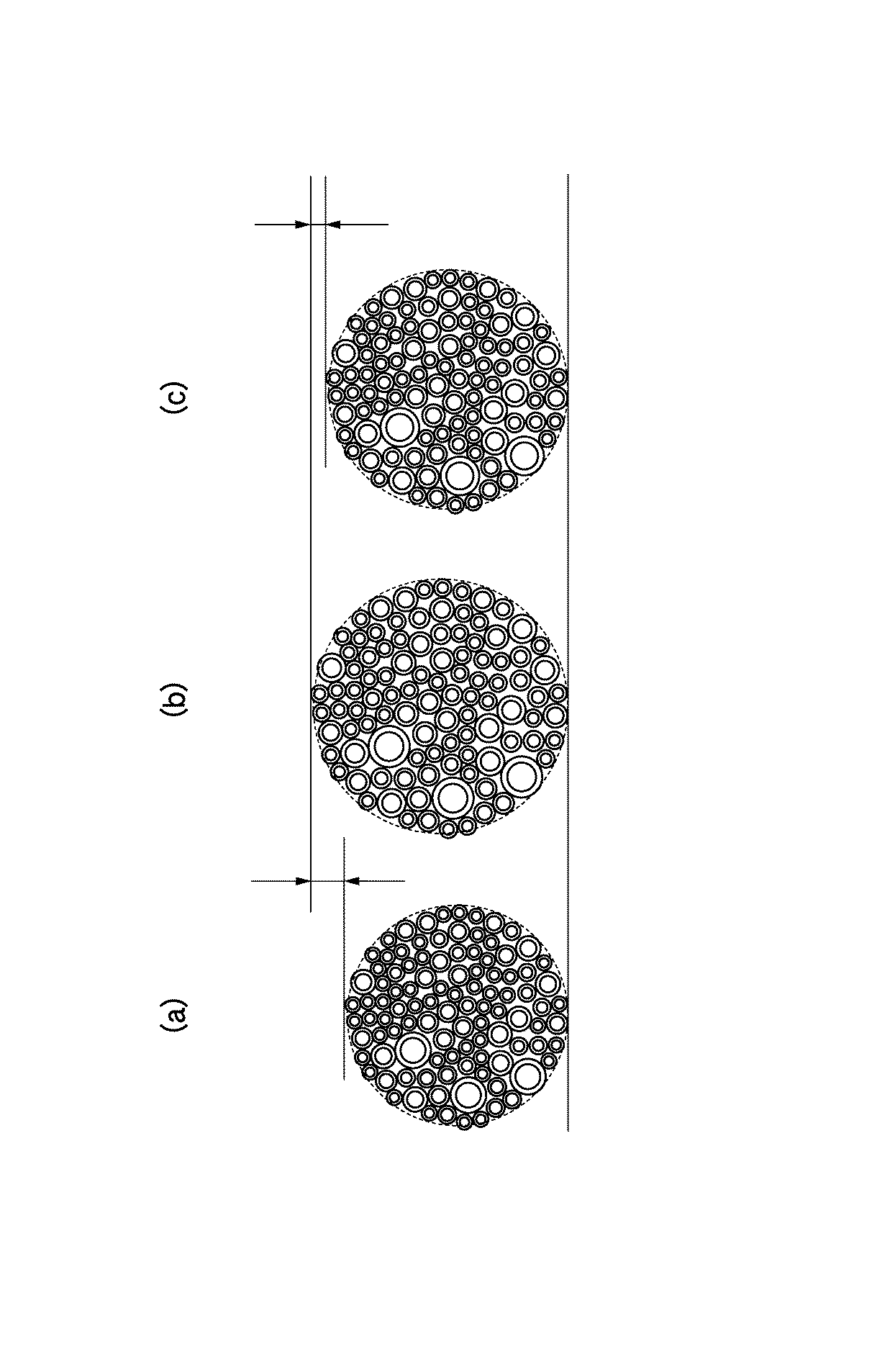
このように構成することにより、図2(c)に示すように、ワイヤーハーネス全体の外径の肥大化を抑制することができる。すなわち、図2(b)に示す比較例では、図2(a)に示す従来例のワイヤーハーネス(全部の電線を銅電線で構成したワイヤーハーネス)に対して肥大化しずぎる嫌いがあるが、図2(c)に示す本実施形態では、図2(b)に示す比較例に比して肥大化を抑制することができる。また、表2及び表3の下欄を見れば分かるように、電線質量も従来例に比べて小さくできる。 By comprising in this way, as shown in FIG.2 (c), the enlargement of the outer diameter of the whole wire harness can be suppressed. That is, in the comparative example shown in FIG. 2B, there is a dislike that the conventional wire harness shown in FIG. In the present embodiment shown in FIG. 2C, the enlargement can be suppressed as compared with the comparative example shown in FIG. Further, as can be seen from the lower columns of Tables 2 and 3, the electric wire mass can be reduced as compared with the conventional example.
上述した極細電線とは、JASO D 611(自動車部品:低圧電線)に規定されるCAVUS(0.3mm2(又はCHFUSO 0.35mm2)未満の電線、つまり、サイズ0.22mm2やサイズ0.13mm2)のことである。この極細電線は、外径1.1mm未満であり、許容電流が数mA〜5A、質量:約4.2g/m未満のものである。各サイズの導体抵抗、外径、質量の一例を表4に示す。 The above-mentioned extra fine electric wire is an electric wire of less than CAVUS (0.3 mm 2 (or CHFUSO 0.35 mm 2 ) defined in JASO D 611 (automotive parts: low-voltage electric wire), that is, size 0.22 mm 2 or size 0. 13 mm 2 ). This extra fine wire has an outer diameter of less than 1.1 mm, an allowable current of several mA to 5 A, and a mass of less than about 4.2 g / m. Table 4 shows an example of the conductor resistance, outer diameter, and mass of each size.
以上説明したように、極細電線を使用することにより、ワイヤーハーネス全体の外径の肥大化を抑制しながら軽量化が図れるようになる。 As described above, by using an extra fine wire, the weight can be reduced while suppressing an increase in the outer diameter of the entire wire harness.
なお、本発明は、上述した実施形態に限定されるものではなく、適宜、変形、改良、等が可能である。その他、上述した実施形態における各構成要素の材質、形状、寸法、数、配置箇所、等は本発明を達成できるものであれば任意であり、限定されない。 In addition, this invention is not limited to embodiment mentioned above, A deformation | transformation, improvement, etc. are possible suitably. In addition, the material, shape, dimensions, number, arrangement location, and the like of each component in the above-described embodiment are arbitrary and are not limited as long as the present invention can be achieved.
ここで、上述した本発明に係るワイヤーハーネスの実施形態の特徴をそれぞれ以下(1)〜(4)に簡潔に纏めて列記する。
(1) 第1の回路に接続される第1の電線(大電流・アース用電線10A、小電流用電線10B)の群と、
前記第1の回路よりも消費電流が小さい第2の回路に接続される第2の電線(信号用電線10C)の群と、
を備えるワイヤーハーネス(1)であって、
前記第1の電線の群は、アルミ電線を含み、
前記第2の電線の群は、アルミニウムまたはアルミニウム合金によって導体が形成された大径電線と、銅または銅合金によって導体が形成された、前記大径電線よりも導体の断面積が小さい小径電線と、銅または銅合金によって導体が形成された、前記小径電線よりも導体の断面積が小さい極細電線と、を含む、
ことを特徴とするワイヤーハーネス。
(2) 上記(1)の構成のワイヤーハーネスにおいて、
前記第2の回路は、信号回路である、
ことを特徴とするワイヤーハーネス。
(3) アルミ電線を含む複数本の電線を集束して形成されたワイヤーハーネス(1)であって、
前記複数本の電線のうち、導体を銅または銅合金によって形成した場合に導体の断面積が0.3mm2以下となる消費電流が小さい回路に接続される電線の群は、アルミニウムまたはアルミニウム合金によって導体が形成された該導体の断面積が0.3mm2よりも大きい大径電線と、銅または銅合金によって導体が形成された該導体の断面積が0.3mm2である小径電線と、銅または銅合金によって導体が形成された該導体の断面積が0.3mm2未満である極細電線と、を含んで構成される
ことを特徴とするワイヤーハーネス。
(4) アルミ電線を含む複数本の電線を集束して形成されたワイヤーハーネス(1)であって、
前記複数本の電線のうち、導体を銅または銅合金によって形成した場合に導体の断面積が0.35mm2以下となる消費電流が小さい回路に接続される電線の群は、アルミニウムまたはアルミニウム合金によって導体が形成された該導体の断面積が0.35mm2よりも大きい大径電線と、銅または銅合金によって導体が形成された該導体の断面積が0.35mm2である小径電線と、銅または銅合金によって導体が形成された該導体の断面積が0.35mm2未満である極細電線と、を含んで構成される
ことを特徴とするワイヤーハーネス。
Here, the characteristics of the embodiment of the wire harness according to the present invention described above are briefly summarized and listed in the following (1) to (4), respectively.
(1) a group of first electric wires (large current /
A group of second wires (
A wire harness (1) comprising:
The first group of electric wires includes an aluminum electric wire;
The group of the second electric wires includes a large-diameter electric wire in which a conductor is formed of aluminum or an aluminum alloy, and a small-diameter electric wire in which a conductor is formed of copper or a copper alloy and has a smaller cross-sectional area than the large-diameter electric wire. A conductor formed of copper or a copper alloy, and an ultrafine wire having a smaller cross-sectional area of the conductor than the small-diameter wire,
A wire harness characterized by that.
(2) In the wire harness configured as described in (1) above,
The second circuit is a signal circuit;
A wire harness characterized by that.
(3) A wire harness (1) formed by converging a plurality of electric wires including an aluminum electric wire,
Among the plurality of electric wires, when the conductor is formed of copper or a copper alloy, the group of electric wires connected to a circuit with a small current consumption in which the cross-sectional area of the conductor is 0.3 mm 2 or less is made of aluminum or an aluminum alloy. A large-diameter electric wire having a cross-sectional area larger than 0.3 mm 2 on which the conductor is formed, a small-diameter electric wire having a cross-sectional area of 0.3 mm 2 on which the conductor is formed by copper or copper alloy, and copper Or the wire harness characterized by including the ultrafine electric wire whose cross-sectional area of this conductor with which the conductor was formed with the copper alloy is less than 0.3 mm < 2 >.
(4) A wire harness (1) formed by converging a plurality of electric wires including an aluminum electric wire,
Among the plurality of electric wires, when the conductor is made of copper or a copper alloy, the group of electric wires connected to a circuit with a small current consumption in which the cross-sectional area of the conductor is 0.35 mm 2 or less is made of aluminum or an aluminum alloy. a large radial electric line is greater than the cross-sectional area of the conductor where the conductor is formed is 0.35 mm 2, and the small diameter wire is the cross-sectional area of the copper or copper alloy conductor the conductor is formed by the 0.35 mm 2, copper Or the wire harness characterized by including including the ultrafine electric wire whose cross-sectional area of this conductor with which the conductor was formed with the copper alloy is less than 0.35 mm < 2 >.
1 ワイヤーハーネス
10 電線
11 導体
12 被覆材
10A 大電流・アース用電線(第1の電線)
11A 導体
12A 被覆材
10B 小電流用電線(第1の電線)
11B 導体
12B 被覆材
10C 信号用電線(第2の電線)
11C 導体
12C 被覆材
DESCRIPTION OF SYMBOLS 1
Claims (4)
前記第1の回路よりも消費電流が小さい第2の回路に接続される第2の電線の群と、
を備えるワイヤーハーネスであって、
前記第1の電線の群は、銅電線及びアルミ電線を含み、
前記第2の電線の群は、アルミニウムまたはアルミニウム合金によって導体が形成された大径電線と、銅または銅合金によって導体が形成された、前記大径電線よりも導体の断面積が小さい小径電線と、銅または銅合金によって導体が形成された、前記小径電線よりも導体の断面積が小さい極細電線と、を含む、
ことを特徴とするワイヤーハーネス。 A first group of electrical wires connected to the first circuit;
A second group of wires connected to a second circuit that consumes less current than the first circuit;
A wire harness comprising:
The first group of electric wires includes a copper electric wire and an aluminum electric wire,
The group of the second electric wires includes a large-diameter electric wire in which a conductor is formed of aluminum or an aluminum alloy, and a small-diameter electric wire in which a conductor is formed of copper or a copper alloy and has a smaller cross-sectional area than the large-diameter electric wire. A conductor formed of copper or a copper alloy, and an ultrafine wire having a smaller cross-sectional area of the conductor than the small-diameter wire,
A wire harness characterized by that.
ことを特徴とする請求項1に記載のワイヤーハーネス。 The second circuit is a signal circuit;
The wire harness according to claim 1.
ことを特徴とする請求項1又は2に記載のワイヤーハーネス。 The sectional area of the conductor of the large radial electric wire 0.3 mm 2, the cross-sectional area of the conductor of the small-diameter wire is the 0.3 mm 2, the cross-sectional area of the conductor of the superfine wire 0.3 mm 2 Is less than
The wire harness according to claim 1 or 2, characterized in that.
ことを特徴とする請求項1又は2に記載のワイヤーハーネス。 The sectional area of the conductor of the large radial electric wire 0.35 mm 2, the cross-sectional area of the conductor of the small-diameter wire is the 0.35 mm 2, the cross-sectional area of the conductor of the ultrafine wire 0.35 mm 2 Is less than
The wire harness according to claim 1 or 2, characterized in that.
Priority Applications (4)
| Application Number | Priority Date | Filing Date | Title |
|---|---|---|---|
| JP2014041745A JP6235936B2 (en) | 2014-03-04 | 2014-03-04 | Wire Harness |
| CN201580011745.0A CN106062892B (en) | 2014-03-04 | 2015-03-04 | Harness |
| PCT/JP2015/056430 WO2015133549A1 (en) | 2014-03-04 | 2015-03-04 | Wire harness |
| US15/255,492 US10381130B2 (en) | 2014-03-04 | 2016-09-02 | Wire harness |
Applications Claiming Priority (1)
| Application Number | Priority Date | Filing Date | Title |
|---|---|---|---|
| JP2014041745A JP6235936B2 (en) | 2014-03-04 | 2014-03-04 | Wire Harness |
Publications (2)
| Publication Number | Publication Date |
|---|---|
| JP2015167114A JP2015167114A (en) | 2015-09-24 |
| JP6235936B2 true JP6235936B2 (en) | 2017-11-22 |
Family
ID=54055352
Family Applications (1)
| Application Number | Title | Priority Date | Filing Date |
|---|---|---|---|
| JP2014041745A Active JP6235936B2 (en) | 2014-03-04 | 2014-03-04 | Wire Harness |
Country Status (4)
| Country | Link |
|---|---|
| US (1) | US10381130B2 (en) |
| JP (1) | JP6235936B2 (en) |
| CN (1) | CN106062892B (en) |
| WO (1) | WO2015133549A1 (en) |
Families Citing this family (4)
| Publication number | Priority date | Publication date | Assignee | Title |
|---|---|---|---|---|
| CN109923621B (en) | 2016-11-08 | 2021-02-09 | 株式会社自动网络技术研究所 | Electric wire conductor, coated electric wire, and wire harness |
| CN112086224B (en) * | 2016-11-08 | 2022-05-13 | 株式会社自动网络技术研究所 | Electric wire conductor, coated electric wire, and wire harness |
| JP2018078007A (en) * | 2016-11-09 | 2018-05-17 | 矢崎総業株式会社 | Aluminum twisted-wire and wire harness |
| JP7456245B2 (en) * | 2019-11-12 | 2024-03-27 | 株式会社オートネットワーク技術研究所 | Wire Harness |
Family Cites Families (13)
| Publication number | Priority date | Publication date | Assignee | Title |
|---|---|---|---|---|
| FR2353120A1 (en) * | 1976-05-25 | 1977-12-23 | Cables De Lyon Geoffroy Delore | UNDERWATER TELEPHONE CABLE |
| US4471161A (en) * | 1983-02-16 | 1984-09-11 | Essex Group, Inc. | Conductor strand formed of solid wires and method for making the conductor strand |
| US4628151A (en) * | 1985-12-30 | 1986-12-09 | Cardas George F | Multi-strand conductor cable having its strands sized according to the golden section |
| US4689444A (en) * | 1986-07-25 | 1987-08-25 | Rockwell International Corporation | Electrical cable apparatus |
| US6311394B1 (en) * | 1999-08-09 | 2001-11-06 | Nextrom, Ltd. | Combination 37-wire unilay stranded conductor and method and apparatus for forming the same |
| US20050121222A1 (en) * | 2003-12-03 | 2005-06-09 | Chang-Chi Lee | Audio and video signal cable |
| JP5177848B2 (en) * | 2007-12-21 | 2013-04-10 | 矢崎総業株式会社 | Composite wire |
| JP5407141B2 (en) * | 2008-01-11 | 2014-02-05 | 株式会社オートネットワーク技術研究所 | Automotive wire harness |
| JP5463618B2 (en) * | 2008-01-11 | 2014-04-09 | 株式会社オートネットワーク技術研究所 | Automotive wire harness |
| JP2012119073A (en) * | 2010-11-29 | 2012-06-21 | Yazaki Corp | Stranded conductor for insulated wire |
| JP2013045529A (en) * | 2011-08-22 | 2013-03-04 | Auto Network Gijutsu Kenkyusho:Kk | Wire and wire harness for automobile |
| CN102509576B (en) * | 2011-09-29 | 2014-05-28 | 东华大学 | High-vacuum-resistant high-temperature-resistant wire cable and preparation method thereof |
| JP5986832B2 (en) * | 2012-07-12 | 2016-09-06 | 矢崎総業株式会社 | Wire harness |
-
2014
- 2014-03-04 JP JP2014041745A patent/JP6235936B2/en active Active
-
2015
- 2015-03-04 WO PCT/JP2015/056430 patent/WO2015133549A1/en active Application Filing
- 2015-03-04 CN CN201580011745.0A patent/CN106062892B/en active Active
-
2016
- 2016-09-02 US US15/255,492 patent/US10381130B2/en active Active
Also Published As
| Publication number | Publication date |
|---|---|
| CN106062892B (en) | 2019-03-29 |
| US10381130B2 (en) | 2019-08-13 |
| CN106062892A (en) | 2016-10-26 |
| US20160372231A1 (en) | 2016-12-22 |
| WO2015133549A1 (en) | 2015-09-11 |
| JP2015167114A (en) | 2015-09-24 |
Similar Documents
| Publication | Publication Date | Title |
|---|---|---|
| JP6235936B2 (en) | Wire Harness | |
| JP5177848B2 (en) | Composite wire | |
| US9537294B2 (en) | Integrated shielding protector and wire harness | |
| EP2884501B1 (en) | Multi-layer coaxial cable | |
| JP5177849B2 (en) | Composite wire | |
| JP2019021592A (en) | Conductive wire and wire harness | |
| US9592774B2 (en) | Wire harness | |
| JP2015022894A (en) | Wire harness | |
| US6303868B1 (en) | Wire conductor for harness | |
| JP2013045529A (en) | Wire and wire harness for automobile | |
| JP7010617B2 (en) | Vehicle circuit | |
| JP5407141B2 (en) | Automotive wire harness | |
| JP2014150022A (en) | Insulated wire | |
| JP5463618B2 (en) | Automotive wire harness | |
| US20140034383A1 (en) | Wire harness | |
| WO2016088788A1 (en) | Wire harness and power supply device for automobile | |
| JP2016207273A (en) | Wire for automobile | |
| JP2020103000A (en) | Wire harness | |
| JP2019114496A (en) | Wiring system | |
| JP2005197135A (en) | Power supply line for automobile | |
| JP2015020655A (en) | Electric wire component | |
| DE102014109269B4 (en) | Energy supply system for a motor vehicle | |
| JP2022142635A (en) | Electric wire for communication | |
| JP6007093B2 (en) | Electrical junction box wiring structure | |
| KR200418384Y1 (en) | twisted electric cord |
Legal Events
| Date | Code | Title | Description |
|---|---|---|---|
| A621 | Written request for application examination |
Free format text: JAPANESE INTERMEDIATE CODE: A621 Effective date: 20170216 |
|
| A131 | Notification of reasons for refusal |
Free format text: JAPANESE INTERMEDIATE CODE: A131 Effective date: 20170801 |
|
| A521 | Request for written amendment filed |
Free format text: JAPANESE INTERMEDIATE CODE: A523 Effective date: 20170913 |
|
| TRDD | Decision of grant or rejection written | ||
| A01 | Written decision to grant a patent or to grant a registration (utility model) |
Free format text: JAPANESE INTERMEDIATE CODE: A01 Effective date: 20171003 |
|
| A61 | First payment of annual fees (during grant procedure) |
Free format text: JAPANESE INTERMEDIATE CODE: A61 Effective date: 20171027 |
|
| R150 | Certificate of patent or registration of utility model |
Ref document number: 6235936 Country of ref document: JP Free format text: JAPANESE INTERMEDIATE CODE: R150 |
|
| R250 | Receipt of annual fees |
Free format text: JAPANESE INTERMEDIATE CODE: R250 |
|
| R250 | Receipt of annual fees |
Free format text: JAPANESE INTERMEDIATE CODE: R250 |
|
| R250 | Receipt of annual fees |
Free format text: JAPANESE INTERMEDIATE CODE: R250 |
|
| S531 | Written request for registration of change of domicile |
Free format text: JAPANESE INTERMEDIATE CODE: R313531 |
|
| R350 | Written notification of registration of transfer |
Free format text: JAPANESE INTERMEDIATE CODE: R350 |
|
| R250 | Receipt of annual fees |
Free format text: JAPANESE INTERMEDIATE CODE: R250 |