JP6235011B2 - Balloon catheter with improved positioning performance - Google Patents
Balloon catheter with improved positioning performance Download PDFInfo
- Publication number
- JP6235011B2 JP6235011B2 JP2015524424A JP2015524424A JP6235011B2 JP 6235011 B2 JP6235011 B2 JP 6235011B2 JP 2015524424 A JP2015524424 A JP 2015524424A JP 2015524424 A JP2015524424 A JP 2015524424A JP 6235011 B2 JP6235011 B2 JP 6235011B2
- Authority
- JP
- Japan
- Prior art keywords
- balloon
- radiopaque
- balloon catheter
- marking
- shaft
- Prior art date
- Legal status (The legal status is an assumption and is not a legal conclusion. Google has not performed a legal analysis and makes no representation as to the accuracy of the status listed.)
- Active
Links
- 239000000463 material Substances 0.000 claims description 20
- 210000004204 blood vessel Anatomy 0.000 claims description 18
- 239000003814 drug Substances 0.000 claims description 15
- 229940079593 drug Drugs 0.000 claims description 9
- 239000012530 fluid Substances 0.000 claims description 4
- 238000003780 insertion Methods 0.000 claims description 4
- 230000037431 insertion Effects 0.000 claims description 4
- 239000003550 marker Substances 0.000 description 81
- 238000000034 method Methods 0.000 description 26
- 238000005259 measurement Methods 0.000 description 19
- 239000002872 contrast media Substances 0.000 description 11
- 230000003902 lesion Effects 0.000 description 11
- 230000001225 therapeutic effect Effects 0.000 description 8
- 210000005166 vasculature Anatomy 0.000 description 8
- 238000002399 angioplasty Methods 0.000 description 6
- 229940124597 therapeutic agent Drugs 0.000 description 5
- TZCXTZWJZNENPQ-UHFFFAOYSA-L barium sulfate Chemical compound [Ba+2].[O-]S([O-])(=O)=O TZCXTZWJZNENPQ-UHFFFAOYSA-L 0.000 description 4
- 238000013152 interventional procedure Methods 0.000 description 4
- FAPWRFPIFSIZLT-UHFFFAOYSA-M Sodium chloride Chemical compound [Na+].[Cl-] FAPWRFPIFSIZLT-UHFFFAOYSA-M 0.000 description 3
- 239000011780 sodium chloride Substances 0.000 description 3
- ZCYVEMRRCGMTRW-UHFFFAOYSA-N 7553-56-2 Chemical compound [I] ZCYVEMRRCGMTRW-UHFFFAOYSA-N 0.000 description 2
- CURLTUGMZLYLDI-UHFFFAOYSA-N Carbon dioxide Chemical compound O=C=O CURLTUGMZLYLDI-UHFFFAOYSA-N 0.000 description 2
- 239000004952 Polyamide Substances 0.000 description 2
- 239000000853 adhesive Substances 0.000 description 2
- 230000001070 adhesive effect Effects 0.000 description 2
- 230000008901 benefit Effects 0.000 description 2
- 229910052797 bismuth Inorganic materials 0.000 description 2
- JCXGWMGPZLAOME-UHFFFAOYSA-N bismuth atom Chemical compound [Bi] JCXGWMGPZLAOME-UHFFFAOYSA-N 0.000 description 2
- WMWLMWRWZQELOS-UHFFFAOYSA-N bismuth(III) oxide Inorganic materials O=[Bi]O[Bi]=O WMWLMWRWZQELOS-UHFFFAOYSA-N 0.000 description 2
- 238000000576 coating method Methods 0.000 description 2
- 238000002594 fluoroscopy Methods 0.000 description 2
- 239000011888 foil Substances 0.000 description 2
- PCHJSUWPFVWCPO-UHFFFAOYSA-N gold Chemical compound [Au] PCHJSUWPFVWCPO-UHFFFAOYSA-N 0.000 description 2
- 229910052737 gold Inorganic materials 0.000 description 2
- 239000010931 gold Substances 0.000 description 2
- 229910052740 iodine Inorganic materials 0.000 description 2
- 239000011630 iodine Substances 0.000 description 2
- 238000012986 modification Methods 0.000 description 2
- 230000004048 modification Effects 0.000 description 2
- 239000003973 paint Substances 0.000 description 2
- BASFCYQUMIYNBI-UHFFFAOYSA-N platinum Chemical compound [Pt] BASFCYQUMIYNBI-UHFFFAOYSA-N 0.000 description 2
- 229920002647 polyamide Polymers 0.000 description 2
- 229920000642 polymer Polymers 0.000 description 2
- 239000000843 powder Substances 0.000 description 2
- 238000002601 radiography Methods 0.000 description 2
- 239000000126 substance Substances 0.000 description 2
- 238000012546 transfer Methods 0.000 description 2
- WFKWXMTUELFFGS-UHFFFAOYSA-N tungsten Chemical compound [W] WFKWXMTUELFFGS-UHFFFAOYSA-N 0.000 description 2
- 229910052721 tungsten Inorganic materials 0.000 description 2
- 239000010937 tungsten Substances 0.000 description 2
- RYECOJGRJDOGPP-UHFFFAOYSA-N Ethylurea Chemical compound CCNC(N)=O RYECOJGRJDOGPP-UHFFFAOYSA-N 0.000 description 1
- HTTJABKRGRZYRN-UHFFFAOYSA-N Heparin Chemical compound OC1C(NC(=O)C)C(O)OC(COS(O)(=O)=O)C1OC1C(OS(O)(=O)=O)C(O)C(OC2C(C(OS(O)(=O)=O)C(OC3C(C(O)C(O)C(O3)C(O)=O)OS(O)(=O)=O)C(CO)O2)NS(O)(=O)=O)C(C(O)=O)O1 HTTJABKRGRZYRN-UHFFFAOYSA-N 0.000 description 1
- JHWNWJKBPDFINM-UHFFFAOYSA-N Laurolactam Chemical compound O=C1CCCCCCCCCCCN1 JHWNWJKBPDFINM-UHFFFAOYSA-N 0.000 description 1
- 229920000571 Nylon 11 Polymers 0.000 description 1
- 229920000299 Nylon 12 Polymers 0.000 description 1
- 229930012538 Paclitaxel Natural products 0.000 description 1
- 229920002614 Polyether block amide Polymers 0.000 description 1
- BQCADISMDOOEFD-UHFFFAOYSA-N Silver Chemical compound [Ag] BQCADISMDOOEFD-UHFFFAOYSA-N 0.000 description 1
- 239000004433 Thermoplastic polyurethane Substances 0.000 description 1
- ATJFFYVFTNAWJD-UHFFFAOYSA-N Tin Chemical compound [Sn] ATJFFYVFTNAWJD-UHFFFAOYSA-N 0.000 description 1
- 238000010521 absorption reaction Methods 0.000 description 1
- 238000004026 adhesive bonding Methods 0.000 description 1
- 210000001367 artery Anatomy 0.000 description 1
- 229940036348 bismuth carbonate Drugs 0.000 description 1
- 150000001622 bismuth compounds Chemical class 0.000 description 1
- 210000000988 bone and bone Anatomy 0.000 description 1
- 229910002092 carbon dioxide Inorganic materials 0.000 description 1
- 239000001569 carbon dioxide Substances 0.000 description 1
- 239000003795 chemical substances by application Substances 0.000 description 1
- 239000011248 coating agent Substances 0.000 description 1
- 150000001875 compounds Chemical class 0.000 description 1
- 230000008602 contraction Effects 0.000 description 1
- 229940039231 contrast media Drugs 0.000 description 1
- GMZOPRQQINFLPQ-UHFFFAOYSA-H dibismuth;tricarbonate Chemical compound [Bi+3].[Bi+3].[O-]C([O-])=O.[O-]C([O-])=O.[O-]C([O-])=O GMZOPRQQINFLPQ-UHFFFAOYSA-H 0.000 description 1
- RCJVRSBWZCNNQT-UHFFFAOYSA-N dichloridooxygen Chemical compound ClOCl RCJVRSBWZCNNQT-UHFFFAOYSA-N 0.000 description 1
- 239000000428 dust Substances 0.000 description 1
- 238000005516 engineering process Methods 0.000 description 1
- 230000007613 environmental effect Effects 0.000 description 1
- 239000000835 fiber Substances 0.000 description 1
- 239000010408 film Substances 0.000 description 1
- 239000000499 gel Substances 0.000 description 1
- 229960002897 heparin Drugs 0.000 description 1
- 229920000669 heparin Polymers 0.000 description 1
- PNDPGZBMCMUPRI-UHFFFAOYSA-N iodine Chemical compound II PNDPGZBMCMUPRI-UHFFFAOYSA-N 0.000 description 1
- DGAIEPBNLOQYER-UHFFFAOYSA-N iopromide Chemical compound COCC(=O)NC1=C(I)C(C(=O)NCC(O)CO)=C(I)C(C(=O)N(C)CC(O)CO)=C1I DGAIEPBNLOQYER-UHFFFAOYSA-N 0.000 description 1
- 229960002603 iopromide Drugs 0.000 description 1
- 229910052741 iridium Inorganic materials 0.000 description 1
- GKOZUEZYRPOHIO-UHFFFAOYSA-N iridium atom Chemical compound [Ir] GKOZUEZYRPOHIO-UHFFFAOYSA-N 0.000 description 1
- 230000001788 irregular Effects 0.000 description 1
- 229920000126 latex Polymers 0.000 description 1
- 239000004816 latex Substances 0.000 description 1
- 239000007788 liquid Substances 0.000 description 1
- 230000004807 localization Effects 0.000 description 1
- 238000004519 manufacturing process Methods 0.000 description 1
- 239000008204 material by function Substances 0.000 description 1
- 238000000691 measurement method Methods 0.000 description 1
- 229910021645 metal ion Inorganic materials 0.000 description 1
- 239000000203 mixture Substances 0.000 description 1
- 239000002105 nanoparticle Substances 0.000 description 1
- 229960001592 paclitaxel Drugs 0.000 description 1
- 239000002245 particle Substances 0.000 description 1
- 238000005192 partition Methods 0.000 description 1
- 230000002093 peripheral effect Effects 0.000 description 1
- 229910052697 platinum Inorganic materials 0.000 description 1
- 239000004417 polycarbonate Substances 0.000 description 1
- 229920000515 polycarbonate Polymers 0.000 description 1
- 229920001296 polysiloxane Polymers 0.000 description 1
- 229920002635 polyurethane Polymers 0.000 description 1
- 239000004814 polyurethane Substances 0.000 description 1
- ZAHRKKWIAAJSAO-UHFFFAOYSA-N rapamycin Natural products COCC(O)C(=C/C(C)C(=O)CC(OC(=O)C1CCCCN1C(=O)C(=O)C2(O)OC(CC(OC)C(=CC=CC=CC(C)CC(C)C(=O)C)C)CCC2C)C(C)CC3CCC(O)C(C3)OC)C ZAHRKKWIAAJSAO-UHFFFAOYSA-N 0.000 description 1
- 229910001404 rare earth metal oxide Inorganic materials 0.000 description 1
- 230000009467 reduction Effects 0.000 description 1
- 230000002787 reinforcement Effects 0.000 description 1
- 238000000926 separation method Methods 0.000 description 1
- 229910052709 silver Inorganic materials 0.000 description 1
- 239000004332 silver Substances 0.000 description 1
- 229940100890 silver compound Drugs 0.000 description 1
- 150000003379 silver compounds Chemical class 0.000 description 1
- 229960002930 sirolimus Drugs 0.000 description 1
- QFJCIRLUMZQUOT-HPLJOQBZSA-N sirolimus Chemical compound C1C[C@@H](O)[C@H](OC)C[C@@H]1C[C@@H](C)[C@H]1OC(=O)[C@@H]2CCCCN2C(=O)C(=O)[C@](O)(O2)[C@H](C)CC[C@H]2C[C@H](OC)/C(C)=C/C=C/C=C/[C@@H](C)C[C@@H](C)C(=O)[C@H](OC)[C@H](O)/C(C)=C/[C@@H](C)C(=O)C1 QFJCIRLUMZQUOT-HPLJOQBZSA-N 0.000 description 1
- 229910052715 tantalum Inorganic materials 0.000 description 1
- GUVRBAGPIYLISA-UHFFFAOYSA-N tantalum atom Chemical compound [Ta] GUVRBAGPIYLISA-UHFFFAOYSA-N 0.000 description 1
- RCINICONZNJXQF-MZXODVADSA-N taxol Chemical compound O([C@@H]1[C@@]2(C[C@@H](C(C)=C(C2(C)C)[C@H](C([C@]2(C)[C@@H](O)C[C@H]3OC[C@]3([C@H]21)OC(C)=O)=O)OC(=O)C)OC(=O)[C@H](O)[C@@H](NC(=O)C=1C=CC=CC=1)C=1C=CC=CC=1)O)C(=O)C1=CC=CC=C1 RCINICONZNJXQF-MZXODVADSA-N 0.000 description 1
- 238000002560 therapeutic procedure Methods 0.000 description 1
- 229920002803 thermoplastic polyurethane Polymers 0.000 description 1
- 229910052718 tin Inorganic materials 0.000 description 1
- 239000011135 tin Substances 0.000 description 1
- 210000001519 tissue Anatomy 0.000 description 1
- 230000007704 transition Effects 0.000 description 1
- 230000002792 vascular Effects 0.000 description 1
- 210000003462 vein Anatomy 0.000 description 1
Images


Classifications
-
- A—HUMAN NECESSITIES
- A61—MEDICAL OR VETERINARY SCIENCE; HYGIENE
- A61M—DEVICES FOR INTRODUCING MEDIA INTO, OR ONTO, THE BODY; DEVICES FOR TRANSDUCING BODY MEDIA OR FOR TAKING MEDIA FROM THE BODY; DEVICES FOR PRODUCING OR ENDING SLEEP OR STUPOR
- A61M25/00—Catheters; Hollow probes
- A61M25/01—Introducing, guiding, advancing, emplacing or holding catheters
- A61M25/0105—Steering means as part of the catheter or advancing means; Markers for positioning
- A61M25/0108—Steering means as part of the catheter or advancing means; Markers for positioning using radio-opaque or ultrasound markers
-
- A—HUMAN NECESSITIES
- A61—MEDICAL OR VETERINARY SCIENCE; HYGIENE
- A61M—DEVICES FOR INTRODUCING MEDIA INTO, OR ONTO, THE BODY; DEVICES FOR TRANSDUCING BODY MEDIA OR FOR TAKING MEDIA FROM THE BODY; DEVICES FOR PRODUCING OR ENDING SLEEP OR STUPOR
- A61M25/00—Catheters; Hollow probes
- A61M25/01—Introducing, guiding, advancing, emplacing or holding catheters
- A61M25/09—Guide wires
-
- A—HUMAN NECESSITIES
- A61—MEDICAL OR VETERINARY SCIENCE; HYGIENE
- A61M—DEVICES FOR INTRODUCING MEDIA INTO, OR ONTO, THE BODY; DEVICES FOR TRANSDUCING BODY MEDIA OR FOR TAKING MEDIA FROM THE BODY; DEVICES FOR PRODUCING OR ENDING SLEEP OR STUPOR
- A61M25/00—Catheters; Hollow probes
- A61M25/10—Balloon catheters
- A61M25/104—Balloon catheters used for angioplasty
-
- A—HUMAN NECESSITIES
- A61—MEDICAL OR VETERINARY SCIENCE; HYGIENE
- A61B—DIAGNOSIS; SURGERY; IDENTIFICATION
- A61B90/00—Instruments, implements or accessories specially adapted for surgery or diagnosis and not covered by any of the groups A61B1/00 - A61B50/00, e.g. for luxation treatment or for protecting wound edges
- A61B90/39—Markers, e.g. radio-opaque or breast lesions markers
- A61B2090/3966—Radiopaque markers visible in an X-ray image
-
- A—HUMAN NECESSITIES
- A61—MEDICAL OR VETERINARY SCIENCE; HYGIENE
- A61B—DIAGNOSIS; SURGERY; IDENTIFICATION
- A61B90/00—Instruments, implements or accessories specially adapted for surgery or diagnosis and not covered by any of the groups A61B1/00 - A61B50/00, e.g. for luxation treatment or for protecting wound edges
- A61B90/39—Markers, e.g. radio-opaque or breast lesions markers
-
- A—HUMAN NECESSITIES
- A61—MEDICAL OR VETERINARY SCIENCE; HYGIENE
- A61M—DEVICES FOR INTRODUCING MEDIA INTO, OR ONTO, THE BODY; DEVICES FOR TRANSDUCING BODY MEDIA OR FOR TAKING MEDIA FROM THE BODY; DEVICES FOR PRODUCING OR ENDING SLEEP OR STUPOR
- A61M25/00—Catheters; Hollow probes
- A61M25/10—Balloon catheters
- A61M2025/1043—Balloon catheters with special features or adapted for special applications
- A61M2025/1047—Balloon catheters with special features or adapted for special applications having centering means, e.g. balloons having an appropriate shape
-
- A—HUMAN NECESSITIES
- A61—MEDICAL OR VETERINARY SCIENCE; HYGIENE
- A61M—DEVICES FOR INTRODUCING MEDIA INTO, OR ONTO, THE BODY; DEVICES FOR TRANSDUCING BODY MEDIA OR FOR TAKING MEDIA FROM THE BODY; DEVICES FOR PRODUCING OR ENDING SLEEP OR STUPOR
- A61M25/00—Catheters; Hollow probes
- A61M25/10—Balloon catheters
- A61M2025/1043—Balloon catheters with special features or adapted for special applications
- A61M2025/1068—Balloon catheters with special features or adapted for special applications having means for varying the length or diameter of the deployed balloon, this variations could be caused by excess pressure
-
- A—HUMAN NECESSITIES
- A61—MEDICAL OR VETERINARY SCIENCE; HYGIENE
- A61M—DEVICES FOR INTRODUCING MEDIA INTO, OR ONTO, THE BODY; DEVICES FOR TRANSDUCING BODY MEDIA OR FOR TAKING MEDIA FROM THE BODY; DEVICES FOR PRODUCING OR ENDING SLEEP OR STUPOR
- A61M25/00—Catheters; Hollow probes
- A61M25/10—Balloon catheters
- A61M2025/1043—Balloon catheters with special features or adapted for special applications
- A61M2025/1079—Balloon catheters with special features or adapted for special applications having radio-opaque markers in the region of the balloon
Landscapes
- Health & Medical Sciences (AREA)
- Life Sciences & Earth Sciences (AREA)
- Heart & Thoracic Surgery (AREA)
- Biomedical Technology (AREA)
- Veterinary Medicine (AREA)
- Public Health (AREA)
- General Health & Medical Sciences (AREA)
- Animal Behavior & Ethology (AREA)
- Engineering & Computer Science (AREA)
- Hematology (AREA)
- Anesthesiology (AREA)
- Pulmonology (AREA)
- Biophysics (AREA)
- Child & Adolescent Psychology (AREA)
- Vascular Medicine (AREA)
- Surgery (AREA)
- Oral & Maxillofacial Surgery (AREA)
- Pathology (AREA)
- Nuclear Medicine, Radiotherapy & Molecular Imaging (AREA)
- Medical Informatics (AREA)
- Molecular Biology (AREA)
- Media Introduction/Drainage Providing Device (AREA)
- Apparatus For Radiation Diagnosis (AREA)
Description
本願は、米国仮特許出願第61/675,168号および第61/788,938号の利益を主張し、これらの出願の開示は、参照によって本明細書に組み入れられる。 This application claims the benefit of US Provisional Patent Applications Nos. 61 / 675,168 and 61 / 788,938, the disclosures of which applications are incorporated herein by reference.
本開示は、概して、血管形成術などの医療処置を行うためのバルーンカテーテルに関し、より詳細には、使用中に正確に位置の特定または識別を行うことができる、所定の部分(例えば、作用面)を有するカテーテルに関する。 The present disclosure relates generally to balloon catheters for performing medical procedures such as angioplasty, and more particularly to predetermined portions (eg, working surfaces) that can be accurately located or identified during use. ).
バルーンを備えるカテーテルは、通常、流量制限を解決もしくは対処するために、または、おそらくは、身体のチューブ状の領域(例えば、動脈、静脈)の閉塞を完成させることにさえ使用されてきた。多くの臨床の状況では、制限は、固い個体(例えば、石灰化プラーク)によって引き起こされ、場合によっては、そのような閉塞を圧縮する高圧の使用を伴うことがある。商業的には、利用可能なバルーンには、バルーンのプロファイルを犠牲にすることなく高圧条件を達成するために、複雑な技術が使用される。高圧条件に加えて、バルーンは、特に、血管形成術に使用される場合には、耐穿刺性を有し、進行や押すことが行いやすく、低プロファイルを提供するべきである。 Catheters with balloons have typically been used to solve or address flow restrictions, or perhaps even to complete occlusion of a tubular region (eg, artery, vein) of the body. In many clinical situations, limitations are caused by hard individuals (eg, calcified plaques) and in some cases may involve the use of high pressure to compress such occlusions. Commercially available balloons use complex techniques to achieve high pressure conditions without sacrificing the balloon profile. In addition to high pressure conditions, the balloon should be puncture resistant, easy to advance and push, and provide a low profile, especially when used in angioplasty.
臨床診療では、血管形成バルーン12は、血管内において治療領域T(例えば、血管Vの内周壁の一部分)のところで、収縮し折り畳まれた状態(図1)から膨張し拡張した状態(図2)まで拡張可能である。膨張は、図3および図4に示されるように、インターベンション手順中にX線エネルギーXRまたは他の形態のラジオグラフィーのもとでより良い視認性を提供するために、高さDまでバルーン12を充填するX線造影剤すなわち媒体CMを使用して達成されることができる。典型的には、血管形成術中にバルーンを膨張させるために、造影剤と生理食塩水との70/30%混合が使用される。
In clinical practice, the
一般的に、望まれる目標は、バルーンのプロファイルを犠牲にすることなく、バルーン(特に、容積が大きなバルーン(造影剤を使用する場合、2分までの膨張/収縮時間が要求され得る))に必要な膨張時間および収縮時間を低減することである。造影剤は比較的高い粘性を有するので、バルーンの膨張/収縮に使用される造影剤を不要とするか、少なくともその量を低減することが望ましい。造影剤を使用することによって膨張/収縮時間が長くなり、また、ヨウ素に敏感な患者に対するヨウ素被ばくのリスクがもたらされる。この点について、造影剤に代えて、非X線不透過性物質(例えば、生理食塩水、炭酸ガスなど)を使用することができるが、そのような物質は、X線撮影の際に見ることができず、このため、所望の態様でバルーン12の位置を特定する助けにはならない。
In general, the desired goal is for balloons (especially large volume balloons (expansion / deflation times of up to 2 minutes may be required when using contrast agents) without sacrificing the balloon profile. Reducing the required expansion and contraction time. Since contrast agents have a relatively high viscosity, it is desirable to eliminate or at least reduce the amount of contrast agent used for balloon inflation / deflation. The use of contrast agents increases the inflation / deflation time and poses a risk of iodine exposure for iodine sensitive patients. In this regard, non-radiopaque substances (eg, saline, carbon dioxide, etc.) can be used in place of contrast agents, but such substances should be viewed during radiography. And therefore does not help to locate the
さらに、血管形成術を実施する臨床医は、バルーンが膨張された後に適切に位置決めされるように、膨張していないバルーンの位置を正確に特定することができるべきである。これは、従来、バルーンの作用面の各端部に対応するマーカーバンドをカテーテルシャフトに付けることによって達成されている。この「作用面」は、所望の治療効果(例えば、石灰化プラークに接触すること)を達成するために使用される、バルーンの部分に沿った表面である(この表面は、円錐状またはテーパ状の部位を近位端および遠位端に有するバルーンの場合には、典型的には、略円筒状の胴部と一緒に延在する)。 Furthermore, the clinician performing the angioplasty should be able to pinpoint the position of the uninflated balloon so that it is properly positioned after the balloon is inflated. This is conventionally accomplished by attaching a marker band to the catheter shaft corresponding to each end of the working surface of the balloon. This “working surface” is the surface along the portion of the balloon that is used to achieve the desired therapeutic effect (eg, contact with calcified plaque) (this surface is conical or tapered) In the case of a balloon having a proximal end and a distal end, it typically extends with a generally cylindrical barrel).
シャフトに沿って配置する間のマーカーバンドの位置ズレは、場合によっては、図5に示されるように、作用面の範囲に正確に対応する失敗を生じさせる(シャフトSによって運ばれるマーキングMとして機能する各内部マーカーバンドと、バルーン12の作用面Wと、の位置ズレ量Xに留意されたい。バルーン12は、典型的には、遠位端のところにX線不透過性先端Pを備える)。バルーンが膨張されたときに作用面の予想される境界と整合する内部のシャフト上にマーキングを適切に位置決めすることに大きな注意を払っている場合でさえ、いくつかの可能性のある要因に起因して依然として不一致が生じやすい。そのような要因の1つは、カテーテルシャフトの遠位端にバルーンを取り付けた結果として生じる公差の累積である場合がある。また、バルーンは、膨張されるときに長手方向に大きくなる傾向があり、この傾向は、特に、大きく非常に長いバルーンで生じる。他の要因は、膨張中にバルーン内でのカテーテルシャフトの位置が曲がる(撓む)傾向である。このことは、シャフトSに固定されたマーキングMと、作用面Wと、の位置ズレにつながることがある。
The misalignment of the marker band during placement along the shaft may cause a failure that exactly corresponds to the extent of the working surface, as shown in FIG. 5 (functioning as a marking M carried by the shaft S). Note the amount of misalignment X between each internal marker band that acts and the working surface W of the
原因が何であれ、結果として生じる位置ズレによって、臨床医がインターベンション手順中にバルーンの作用面の位置を正確に識別することが阻止される。このことは、地理的な置き違え、すなわち、治療領域とバルーンの作用面との意図する接触の「ミス」につながり得る。バルーンがペイロード(例えば、薬剤、ステント、または、その両方)または作用要素(例えば、カッター、フォーカスフォースワイヤなど)を血管系の特定の位置に移送するように構成されている場合、そのような結果を回避することが特に好ましい。それは、(例えば、薬剤コーティングされたバルーンの場合、バルーンの再配置または他のバルーンカテーテルの使用が必要になることによって)ミスによって手順の時間が長くなり得るからである。 Whatever the cause, the resulting misalignment prevents the clinician from accurately identifying the position of the working surface of the balloon during the interventional procedure. This can lead to geographic misplacement, i.e., a "miss" of intended contact between the treatment area and the working surface of the balloon. Such results if the balloon is configured to transport a payload (eg, drug, stent, or both) or a working element (eg, cutter, focus force wire, etc.) to a specific location in the vasculature. It is particularly preferred to avoid That is because mistakes can lengthen the procedure time (eg, in the case of drug-coated balloons, by requiring balloon repositioning or the use of other balloon catheters).
身体の外部の場所から病変部位の長さを見積もるために、臨床医は、外部物差し(これの一形態は、いわゆる「LeMaitre」テープである)を使用することがある。そのような物差しまたはテープを使用することによって、病変部位の長さ、および、予備拡張によって治療される領域をより正確に見積もることが可能になる一方で、それには制約がないわけではない。一例として、病変部位の縁部の明確な位置での位置ズレすなわち位置差は、異なる2つの視線に沿って見るときに生じる。この「視差」は、不正確な測定を招くことがあり、また、少なくとも、病変部位に対する作用面の地理的な不整合に寄与する。また、そのような外部物差しを使用することによって、組織での血管系が大きく曲がっている場合に、測定精度の低下を招き得る。 To estimate the length of the lesion site from a location outside the body, the clinician may use an external ruler (one form of this is the so-called “LeMaitre” tape). While using such a ruler or tape makes it possible to more accurately estimate the length of the lesion site and the area to be treated by predilation, it is not without limitations. As an example, a positional shift or position difference at a clear position of the edge of a lesion site occurs when viewing along two different lines of sight. This “parallax” can lead to inaccurate measurements and at least contributes to the geographical mismatch of the working surface with respect to the lesion site. In addition, the use of such an external ruler can lead to a decrease in measurement accuracy when the vascular system in the tissue is bent greatly.
したがって、インターベンション手順中に向上した精度で作用面を識別できるバルーンが求められる。1つの解決策では、カテーテルシャフト上の固定位置とバルーンとの起こりえる不一致を考慮して、作用面を形成する。他の解決策では、治療領域において向上した精度でバルーンカテーテルを血管系に位置決めする方法が提供される。概して、コストまたは複雑さが著しく増大することなく、また、大きな変更を行うことなく多くの既存のカテーテル技術に適用できる態様で、作業効率が向上する。 Therefore, there is a need for a balloon that can identify a working surface with improved accuracy during an interventional procedure. In one solution, the working surface is formed taking into account possible mismatches between the fixed position on the catheter shaft and the balloon. In another solution, a method is provided for positioning a balloon catheter in the vasculature with improved accuracy in the treatment area. In general, operational efficiency is improved in a manner that can be applied to many existing catheter technologies without significant increase in cost or complexity and without major changes.
本開示の目的は、インターベンション手順中に向上した精度で作用面の位置を特定することができるバルーンを提供することである。さらなる目的は、例えば、後続のインターベンション中に治療を提供するために、血管系内の位置の測定を容易に行うことである。 An object of the present disclosure is to provide a balloon that can locate the working surface with improved accuracy during an interventional procedure. A further object is to facilitate measurement of position within the vasculature, eg, to provide therapy during subsequent interventions.
本開示の一態様によれば、治療領域を治療するために血管に挿入するためのバルーンカテーテルは、バルーンの内部でカテーテルの長手方向軸線に沿って間隔が隔てられた少なくとも3つのX線不透過性マーキングすなわちマーカーを備えている。第1のX線不透過性マーキングすなわちマーカーを第2のX線不透過性マーキングすなわちマーカーから離間させる第1の距離は、第2のX線不透過性マーキングすなわちマーカーを隣接する第3のX線不透過性マーキングから離間させる第2の距離と異なっている。 In accordance with one aspect of the present disclosure, a balloon catheter for insertion into a blood vessel to treat a treatment area includes at least three radiopaque interiors spaced along the longitudinal axis of the catheter within the balloon. Has sex markings or markers. The first distance that separates the first radiopaque marking or marker from the second radiopaque marking or marker is the second radiopaque marking or marker that is adjacent to the third radiopaque marking or marker. Different from the second distance away from the line-impermeable marking.
一実施形態では、カテーテルシャフトは、さらに、ガイドワイヤ内腔を形成する内側チューブ状部材を備えており、このチューブ状部材は、少なくとも3つのX線不透過性マーキングすなわちマーカーを備えている。カテーテルシャフトは、第1および第2のX線不透過性マーキングすなわちマーカーのうちの少なくとも一方を有する外壁を備えていてもよい。少なくとも3つのマーキングすなわちマーカーは、カテーテルの遠位先端から間隔が隔てられていてもよい。 In one embodiment, the catheter shaft further comprises an inner tubular member that forms a guidewire lumen, the tubular member comprising at least three radiopaque markings or markers. The catheter shaft may include an outer wall having at least one of first and second radiopaque markings or markers. The at least three markings or markers may be spaced from the distal tip of the catheter.
第1の距離は、第2の距離よりも小さくてもよい。長手方向軸線に沿って、第1のX線不透過性マーキングすなわちマーカーは、第2のX線不透過性マーキングに対して遠位側にあってもよく、第2のX線不透過性マーキングは、第3のX線不透過性マーキングに対して遠位側にあってもよい。X線不透過性マーキングすなわちマーカーは、複数の隣接する対を備えるパターンで配列されていてもよく、隣接する対は、第1および第2の距離だけ交互に離間される。X線不透過性マーキングすなわちマーカーのパターンは、カテーテル上の遠位位置からカテーテル上の近位位置まで徐々に離間距離が大きくなるように互いに間隔が隔てられた隣接する複数のX線不透過性マーキングすなわちマーカーを備えていてもよい。 The first distance may be smaller than the second distance. Along the longitudinal axis, the first radiopaque marking or marker may be distal to the second radiopaque marking and the second radiopaque marking May be distal to the third radiopaque marking. The radiopaque markings or markers may be arranged in a pattern comprising a plurality of adjacent pairs, the adjacent pairs being alternately spaced by a first and a second distance. The radiopaque marking or marker pattern is a plurality of adjacent radiopaques spaced from one another such that the distance increases gradually from a distal location on the catheter to a proximal location on the catheter. A marking or marker may be provided.
これらまたは他の実施形態では、バルーンは、非膨張中央位置と膨張中央位置とを備えている。カテーテルシャフトは、非膨張中央位置に対してオフセットされた位置に位置決めされた少なくとも1つの第1のX線不透過性マーキングすなわちマーカーを備えている。バルーンが膨張する際に、この少なくとも1つのX線不透過性マーキングすなわちマーカーは、膨張中央位置と実質的に整合する。 In these or other embodiments, the balloon has a non-inflated central position and an inflated central position. The catheter shaft includes at least one first radiopaque marking or marker positioned at a position that is offset relative to a non-inflated central position. As the balloon is inflated, the at least one radiopaque marking or marker substantially aligns with the inflation center position.
バルーンカテーテルは、さらに、バルーンの作用面の少なくとも一方の端部に対応する第2のX線不透過性マーキングすなわちマーカーを備えていてもよい。第2のX線不透過性マーキングすなわちマーカーは、バルーン上に設けられてもよく、あるいは、作用面の一端に隣接するバルーンの端部部位に沿って設けられてもよい。また、第3のX線不透過性マーキングすなわちマーカーが作用面の他端に対応する位置に設けられてもよい。 The balloon catheter may further comprise a second radiopaque marking or marker corresponding to at least one end of the working surface of the balloon. The second radiopaque marking or marker may be provided on the balloon or may be provided along the end portion of the balloon adjacent to one end of the working surface. Further, a third radiopaque marking, that is, a marker may be provided at a position corresponding to the other end of the working surface.
上述のオフセット位置は、非膨張中央位置から近位方向または遠位方向に離れていてもよい。一例として、オフセット位置は、膨張状態にあるバルーンの遠位端と近位端との間の長さの約1〜15%の距離だけ非膨張中央位置から離れていてもよい。しかしながら、この離間量は、状況に応じて変わり得る。 The offset position described above may be proximal or distal away from the non-inflated central position. As an example, the offset position may be separated from the uninflated central position by a distance of about 1-15% of the length between the distal and proximal ends of the balloon in an inflated state. However, the amount of separation can vary depending on the situation.
バルーンカテーテルは、さらに、バルーンの内部の外部に、少なくとも1つのX線不透過性マーキングすなわちマーカーを備えていてもよい。この外部X線不透過性マーキングすなわちマーカーは、シャフト上に配置されていてもよい。外側チューブ状シャフトが、膨張流体をバルーンに供給するための膨張内腔を形成してもよく、外部X線不透過性マーキングすなわちマーカーは、外側チューブ状シャフト上に配置されていてもよい。複数のX線不透過性マーキングすなわちマーカーが、バルーンの内部の外部にあってもよく、規則的または不規則に間隔が隔てられていてもよい。 The balloon catheter may further comprise at least one radiopaque marking or marker external to the interior of the balloon. This external radiopaque marking or marker may be located on the shaft. An outer tubular shaft may form an inflation lumen for supplying inflation fluid to the balloon, and an external radiopaque marking or marker may be disposed on the outer tubular shaft. A plurality of radiopaque markings or markers may be external to the interior of the balloon and may be regularly or irregularly spaced.
本開示の他の態様は、治療領域を治療するために血管に挿入されるバルーンカテーテルに関する。このバルーンカテーテルは、カテーテルシャフトと、カテーテルシャフトに取り付けられる膨張可能なバルーンと、を備えている。少なくとも3つのX線不透過性マーキングすなわちマーカーが、カテーテルの長手方向軸線に沿って延在する。第1のX線不透過性マーキングすなわちマーカーを第2のX線不透過性マーキングすなわちマーカーから離隔する非X線不透過性材料の第1の量は、第2のX線不透過性マーキングすなわちマーカーを第3のX線不透過性マーキングから離隔する非X線不透過性材料の第2の量と異なっている(例えば、第1の量の長さは、第2の量の長さよりも長いか、あるいは、短い)。 Another aspect of the present disclosure relates to a balloon catheter that is inserted into a blood vessel to treat a treatment area. The balloon catheter includes a catheter shaft and an inflatable balloon attached to the catheter shaft. At least three radiopaque markings or markers extend along the longitudinal axis of the catheter. The first amount of non-radiopaque material that separates the first radiopaque marking or marker from the second radiopaque marking or marker is the second radiopaque marking or Different from the second amount of non-radiopaque material that separates the marker from the third radiopaque marking (eg, the length of the first amount is greater than the length of the second amount). Long or short).
他の態様では、本開示は、細長いチューブ状のシャフトを備えるバルーンカテーテルに関する。シャフトに指示される膨張可能なバルーンは、非膨張中央位置と膨張中央位置とを備えている。シャフトは、さらに、非膨張中央位置に対してオフセットされた位置に位置決めされた少なくとも1つのX線不透過性マーキングすなわちマーカーを備えている。バルーンが膨張する際、少なくとも1つのX線不透過性マーキングすなわちマーカーは、膨張中央位置と実質的に整合する。 In another aspect, the present disclosure is directed to a balloon catheter comprising an elongated tubular shaft. The inflatable balloon indicated on the shaft has a non-inflated central position and an inflated central position. The shaft further comprises at least one radiopaque marking or marker positioned at a position offset relative to the non-inflated central position. When the balloon is inflated, the at least one radiopaque marking or marker is substantially aligned with the inflation center position.
一実施形態では、第2のX線不透過性マーキングすなわちマーカーは、バルーンの作用面の少なくとも一方の端部に対応している。第2のX線不透過性マーキングすなわちマーカーは、バルーン上に、例えば、作用面の一端に隣接するバルーンの幅狭の端部部位に沿って設けられてもよい。あるいは、第2のX線不透過性マーキングすなわちマーカーは、シャフト上に、作用面の第1の端部に対応する位置に設けられてもよい。第3のX線不透過性マーキングすなわちマーカーは、シャフト上に、作用面の第2の端部に対応する位置に設けられてもよい。 In one embodiment, the second radiopaque marking or marker corresponds to at least one end of the working surface of the balloon. A second radiopaque marking or marker may be provided on the balloon, for example, along the narrow end portion of the balloon adjacent to one end of the working surface. Alternatively, the second radiopaque marking or marker may be provided on the shaft at a location corresponding to the first end of the working surface. A third radiopaque marking or marker may be provided on the shaft at a location corresponding to the second end of the working surface.
本開示のさらなる態様は、細長いチューブ状のシャフトと、シャフトによって支持される膨張可能なバルーンと、を有するバルーンカテーテルに関する。バルーンは、膨張状態にある中央位置を有する作用面を備えている。少なくとも1つの第1のX線不透過性マーキングすなわちマーカーが、膨張状態において作用面の少なくとも一方の端部の位置に対応している。少なくとも1つの第2のX線不透過性マーキングすなわちマーカーが、作用面の中央位置の位置に対応している。 A further aspect of the present disclosure relates to a balloon catheter having an elongated tubular shaft and an inflatable balloon supported by the shaft. The balloon includes a working surface having a central position in an inflated state. At least one first radiopaque marking or marker corresponds to the position of at least one end of the working surface in the expanded state. At least one second radiopaque marking or marker corresponds to the central position of the working surface.
第1のX線不透過性マーキングすなわちマーカーは、シャフト上に位置していてもよい。さらに、作用面の第2の端部に対応する第3のX線不透過性マーキングすなわちマーカーも設けられてもよい。第3のX線不透過性マーキングすなわちマーカーは、シャフト上に位置していてもよく、第1のX線不透過性マーキングすなわちマーカーは、バルーン上に位置していてもよい。 The first radiopaque marking or marker may be located on the shaft. Furthermore, a third radiopaque marking or marker corresponding to the second end of the working surface may also be provided. The third radiopaque marking or marker may be located on the shaft, and the first radiopaque marking or marker may be located on the balloon.
本開示のさらに別の態様は、細長いチューブ状のシャフトと、シャフトによって支持される膨張可能なバルーンと、を有するバルーンカテーテルに関する。バルーンは、作用面を備えている。第1および第2のX線不透過性マーキングすなわちマーカーが、作用面の両端部の位置にそれぞれ対応しており、第3のX線不透過性マーキングすなわちマーカーが、第1および第2のX線不透過性マーキングすなわちマーカーの間に位置決めされる。 Yet another aspect of the present disclosure relates to a balloon catheter having an elongated tubular shaft and an inflatable balloon supported by the shaft. The balloon has a working surface. The first and second radiopaque markings or markers correspond to the positions of both ends of the working surface, respectively, and the third radiopaque markings or markers are the first and second X-ray markings. Positioned between radiopaque markings or markers.
第3のX線不透過性マーキングすなわちマーカーは、長手方向において、第1および第2のX線不透過性マーキングすなわちマーカーのうちの一方の側にあってもよい。第1および第2のX線不透過性マーキングすなわちマーカーの一方または両方は、シャフト上に設けられてもよい。第3のX線不透過性マーキングすなわちマーカーもシャフト上またはバルーン上に設けられてもよい。 The third radiopaque marking or marker may be on one side of the first and second radiopaque markings or markers in the longitudinal direction. One or both of the first and second radiopaque markings or markers may be provided on the shaft. A third radiopaque marking or marker may also be provided on the shaft or on the balloon.
第1のX線不透過性マーキングすなわちマーカーは、バルーンの近位端側にあってもよく、第3のX線不透過性マーキングすなわちマーカーは、第2のマーキングよりも第1のマーキングすなわちマーカー側にあってもよい。第2のX線不透過性マーキングすなわちマーカーは、バルーンの遠端側にあってもよく、第3のX線不透過性マーキングすなわちマーカーは、第1のマーキングよりも第2のマーキングすなわちマーカー側にあってもよい。 The first radiopaque marking or marker may be on the proximal end side of the balloon, and the third radiopaque marking or marker is the first marking or marker over the second marking. May be on the side. The second radiopaque marking or marker may be on the far end side of the balloon, and the third radiopaque marking or marker is on the second marking or marker side than the first marking. May be.
開示される実施形態のいずれかにおいて、バルーンは、ノンコンプライアントであってもよく、あるいは、コンプライアントまたはセミコンプライアントであってもよい。バルーンは、さらに、例えば、薬剤、ステント、ステントグラフト、または、それらの組み合わせなどの治療手段を備えていてもよい。上述の実施形態のいずれかのバルーンカテーテルは、さらに、血管系内でバルーンを案内するためのガイドワイヤを備えていてもよい。任意の実施形態におけるマーキングすなわちマーカーは、少なくとも部分的にX線不透過性材料から形成されたバンドを備えていてもよい。 In any of the disclosed embodiments, the balloon may be non-compliant, or may be compliant or semi-compliant. The balloon may further comprise a therapeutic means such as, for example, a drug, a stent, a stent graft, or a combination thereof. The balloon catheter of any of the above embodiments may further comprise a guide wire for guiding the balloon within the vasculature. The marking or marker in any embodiment may comprise a band formed at least partially from a radiopaque material.
上述のバルーンカテーテルのいずれかは、上記のX線不透過性マーキングすなわちマーカーのうちの少なくとも2つの間隔に対応する長さを有する作用面を備える他のバルーンカテーテルと組み合わせて使用されてもよい。他のバルーンカテーテルは、上記のX線不透過性マーキングすなわちマーカーのうちの少なくとも2つの間隔に対応する長さを有する治療手段を備えていてもよい。 Any of the balloon catheters described above may be used in combination with other balloon catheters having a working surface having a length corresponding to the spacing of at least two of the radiopaque markings or markers described above. Other balloon catheters may comprise a therapeutic means having a length corresponding to the spacing of at least two of the radiopaque markings or markers described above.
本開示のさらなる態様は、細長いチューブ状のシャフトと、シャフトによって支持されるとともに内部を有する膨張可能なバルーンと、を備えるバルーンカテーテルに関する。複数の第1のX線不透過性マーキングすなわちマーカーがバルーンの近位側に設けられる。複数の第2のX線不透過性マーキングすなわちマーカーがバルーンの内部に設けられる。 A further aspect of the present disclosure relates to a balloon catheter comprising an elongate tubular shaft and an inflatable balloon supported by and having an interior. A plurality of first radiopaque markings or markers are provided on the proximal side of the balloon. A plurality of second radiopaque markings or markers are provided inside the balloon.
チューブ状のシャフトは、内側チューブ状シャフトを備えていてもよく、第1のX線不透過性マーキングすなわちマーカーは、内側チューブ状シャフトと同軸の外側チューブ状シャフト上に設けられる。第1および第2のX線不透過性マーキングすなわちマーカーは、等間隔に、または、非等間隔に配置されていてもよい。複数の第2のX線不透過性マーキングすなわちマーカーは、少なくとも3つのマーキングすなわちマーカーを備えていてもよい。 The tubular shaft may comprise an inner tubular shaft, and the first radiopaque marking or marker is provided on the outer tubular shaft coaxial with the inner tubular shaft. The first and second radiopaque markings or markers may be arranged at regular intervals or at non-equal intervals. The plurality of second radiopaque markings or markers may comprise at least three markings or markers.
また、本開示は、血管形成術を行う上での、バルーンカテーテルの使用方法、または、特許請求の範囲のいずれかのカテーテルの使用方法に関すると捉えることもできる。 In addition, the present disclosure can also be considered to relate to a method of using a balloon catheter or a method of using any of the claims in performing angioplasty.
また、本開示は、治療領域を治療するためにカテーテルを使用する方法に関する。このカテーテルは、シャフトによって運ばれる膨張可能なバルーンを備えていてもよい。このシャフトは、非膨張状態におけるバルーンの中央位置からオフセットされた少なくとも1つのX線不透過性マーキングすなわちマーカーを備えている。この方法は、オフセットされたX線不透過性マーキングすなわちマーカー(これは、非膨張状態のバルーンのシャフト上にあってもよい)を治療領域の中央領域と整合させる工程を備えていてもよい。この方法は、さらに、膨張時にバルーンの作用面が治療領域に対応するようにバルーンを膨張させる工程を備えていてもよい。 The present disclosure also relates to a method of using a catheter to treat a treatment area. The catheter may comprise an inflatable balloon carried by a shaft. The shaft includes at least one radiopaque marking or marker that is offset from the central position of the balloon in the uninflated state. The method may comprise aligning an offset radiopaque marking or marker (which may be on a non-inflated balloon shaft) with the central region of the treatment region. The method may further comprise the step of inflating the balloon such that the working surface of the balloon corresponds to the treatment area when inflated.
本開示のさらなる態様は、ガイドワイヤの使用と組み合わせて、対象者の血管内の距離を測定する方法に関する。この方法は、バルーンと、バルーン内の少なくとも3つのX線不透過性マーキングすなわちマーカーと、を備えるカテーテルを用意する工程を備えている。この方法は、さらに、マーキングすなわちマーカーを使用して血管内の距離を決定する工程を備えている。この決定工程は、血管内の病変部位の長さを測定する工程を備えていてもよく、治療手段を備えるカテーテルを血管内に導入する工程の前に完了されてもよい。 A further aspect of the present disclosure relates to a method for measuring distance within a subject's blood vessels in combination with the use of a guidewire. The method includes providing a catheter comprising a balloon and at least three radiopaque markings or markers within the balloon. The method further comprises determining a distance in the blood vessel using the marking or marker. This determining step may comprise a step of measuring the length of the lesion site in the blood vessel and may be completed prior to the step of introducing the catheter with the therapeutic means into the blood vessel.
また、本開示は、対象者血管内の治療領域に治療薬を適用する方法を説明している。この方法は、複数のX線不透過性マーキングすなわちマーカーを備える測定カテーテルを用意する工程と、測定カテーテルを使用して治療領域の長さを測定する工程と、測定された長さに基づいて、または、対応させて、治療バルーンを用意する工程と、を備えている。この特定カテーテルは、バルーンを備えていてもよく、この方法は、さらに治療部位でバルーンを膨張させる工程を備えていてもよい。測定工程は、測定カテーテル上でバルーンを膨張させる前に行われてもよい。測定工程は、測定カテーテル上でバルーンを膨張させた後に続いて行われてもよい。この方法は、さらに、治療バルーンを治療部位に位置決めして治療薬を治療領域に供給する工程を備えていてもよい。この方法は、さらに、バルーンを備える治療カテーテルを用意する工程を備えていてもよい。このバルーンは、計測カテーテルのマーキングすなわちマーカーと一致する複数のX線不透過性マーキングすなわちマーカーを備えている。治療カテーテルは、計測カテーテルよりも長いバルーンを備えていてもよい。 The present disclosure also describes a method of applying a therapeutic agent to a treatment area within a subject's blood vessel. The method includes the steps of providing a measurement catheter with a plurality of radiopaque markings or markers, measuring the length of the treatment region using the measurement catheter, and based on the measured lengths. Or a step of preparing a treatment balloon correspondingly. The particular catheter may comprise a balloon, and the method may further comprise inflating the balloon at the treatment site. The measuring step may be performed before inflating the balloon on the measuring catheter. The measuring step may be performed subsequently after inflating the balloon on the measuring catheter. The method may further comprise the step of positioning the treatment balloon at the treatment site and delivering the therapeutic agent to the treatment area. The method may further comprise the step of providing a treatment catheter comprising a balloon. The balloon includes a plurality of radiopaque markings or markers that coincide with the markings or markers on the measurement catheter. The treatment catheter may include a longer balloon than the measurement catheter.
本開示は、バルーンカテーテルを提供する。このバルーンカテーテルは、チューブ状のガイドワイヤ部材を有する細長いチューブ状のシャフトと、シャフトによって支持されるとともに内部を有する膨張可能なバルーンと、バルーン内およびバルーンの外部のカテーテルに沿った、チューブ状のガイドワイヤ部材に沿った複数のX線不透過性マーキングと、を備えている。 The present disclosure provides a balloon catheter. The balloon catheter includes an elongate tubular shaft having a tubular guidewire member, an inflatable balloon supported by the shaft and having an interior, and tubular tubes along the catheter inside and outside the balloon. A plurality of radiopaque markings along the guidewire member.
上述の実施形態のいずれかのカテーテルは、ガイドワイヤと組み合わせられてもよく、そのような場合には、使用中が含まれる。 The catheter of any of the embodiments described above may be combined with a guide wire, in such cases including in use.
図面に関して以下に提示される説明は、特に断らない限り、全ての実施形態に適用され、各々の実施形態に共通の特徴は、同様に示され、同様の番号が付されている。 The description presented below with respect to the drawings applies to all embodiments unless otherwise specified, and features common to each embodiment are similarly indicated and numbered similarly.
バルーン12がカテーテルチューブ14に取り付けられた、遠位部分11を有するカテーテル10が提示される。図6,図7および図8を参照すると、膨張時のバルーン12は、中間部位16すなわち「胴部」と、端部部位18,20と、を備えている。一実施形態では、端部部位18,20は、中間部位16をカテーテルチューブ14と接合するために、直径が低減されている(このため、一般的にコーンすなわちコーン部位と称する)。バルーン12は、コーン部位18,20のバルーン端部(近位端15aおよび遠位端15b)のところでシールされ、バルーン12が1つ以上の膨張内腔17を介して膨張できるようになっている。1つ以上の膨張内腔17は、カテーテルチューブ14内を延在し、バルーン12の内部に連通している。
A
上述したように、また、図5および図6を参照して理解できるように、カテーテルチューブ14は、バルーン12を支持するためのシャフトSを備えている。シャフトSは、カテーテル10を通って、バルーン12が配置され得る遠位端に沿って、ガイドワイヤ26を方向付けるガイドワイヤ内腔23を形成する細長いチューブ状のシャフト24であってもよい。バルーン12の遠位端15bのところのコーン部位20は、先端Pに隣接してこのシャフト24に固定されてもよい。反対側の端部のところのバルーン12は、チューブ14に接続されており、長手方向にある程度拡張できるようにするためにシャフト24に対して移動することができる。
As described above and as can be understood with reference to FIGS. 5 and 6, the
図8に示されるように、このガイドワイヤ26は、オーバ・ザ・ワイヤ(OTW)形態を達成するために、カテーテル10の近位端と、コネクタ27の第1のポート25と、を通って内腔23内に延在していてもよい。ただし、ガイドワイヤ26は、ラピッド・エクスチェンジ(RX)構成で提供されてもよい。ラピッド・エクスチェンジ構成では、ガイドワイヤ26は、遠位端側の側方開口14aを出る(図9参照)か、あるいは、バルーン12の遠位側の先端Pに関連する通路を通って供給される(「ショート」RX;図示せず)。膨張内腔17を介してバルーン12の内部区画に流体(例えば、生理食塩水、造影剤、または、その両方)を導入するために、第2のポート29が、例えばコネクタ27を介して、カテーテル10に結合されていてもよい。
As shown in FIG. 8, the
バルーン12は、膨張流体を受け入れるための内部を形成する単層または複層のバルーン壁28を備えていてもよい。バルーン12は、バルーンが膨張されるときに1つ以上の方向のサイズおよび形状を維持するバルーン壁28を有するノンコンプライアントバルーンであってもよい。ノンコンプライアントバルーンの例は、米国特許第6,746,425号、米国特許出願第2006/0085022号、第2006/0085023号、第2006/0085024号に見つけることができ、それらの開示内容は、参照によって組み入れられる。バルーン12は、PETおよび/または繊維の補強材を備えていてもよい。かかる場合、バルーン12は、膨張中および膨張後に実質的に一定に維持される予め定められた表面積を有しており、また、各々または一緒に、膨張中および膨張後に実質的に一定に維持される予め定められた長さおよび直径を有している(材料特性の結果として、比較的少量の長手方向拡張(例えば、5%まで)を被る)。ただし、バルーン12は、それに代えて、特定の使用に応じて、セミコンプライアントまたはコンプライアントであってもよい。コンプライアントバルーンの材料の例には、ラテックスおよびシリコーンが含まれ、セミコンプライアントバルーンの材料の例には、ポリアミド(ナイロン11またはナイロン12)、ポリアミドブロック重合体(Pebax)、ポリウレタン(Pellethane)およびポリカーボネートベースの熱可塑性ポリウレタン(Carbothane)が含まれる。
インターベンション手順中に、潜在的に造影媒体を使用することなく、向上した位置特定性能を提供するために、カテーテル10は、X線不透過性を有していてもよい。一実施形態では、このX線不透過性は、臨床医が所定の治療領域Tのところにバルーン12(特に、バルーンの膨張時に形成される作用面W)を正確に位置決めできる態様で提供される。このことは、以下の説明でより詳細に概説するように、バルーンの作用面Wを介して特定の治療手段(例えば、薬剤またはステント)を移送する上で特に重要となる場合がある。
In order to provide improved localization performance without potentially using contrast media during the interventional procedure, the
一実施形態では、X線不透過性は、カテーテル10に連結された、少なくとも部分的にX線不透過性を有する1つ以上のマーキングすなわちマーカーX線不透過性マーキングすなわちマーカーによって達成されてもよい。第1実施形態では、図10に示すように、この構成は、少なくとも1つのX線不透過性マーキングすなわちマーカーMを備えている。このマーキングすなわちマーカーMは、X線不透過性材料、例えば、バンド30の形態であってもよい。バンド30は、バルーン12の内部を通るシャフト24に連結されてもよい(これは、血管系内を移動しやすくするための非膨張状態の、くるまった、すなわち、折り畳まれた状態で図10に概略的に示されている)。
In one embodiment, radiopacity may be achieved by one or more markings or markers that are at least partially radiopaque coupled to the
マーキング(例えば、バンド30)は、初期位置Oに位置決めされてもよい。この初期位置Oは、非膨張、すなわち、くるまった状態において、バルーン12の中央位置Aからオフセットされていてもよい。図示するように、中央位置Aは、バルーン12が膨張されるときに胴部部位16を形成する折り畳まれたときのバルーン壁28の一部分に沿って、バルーン12の近位端15aと遠位端15bとの間に位置しており、これらから離れている。
The marking (eg, band 30) may be positioned at the initial position O. The initial position O may be offset from the central position A of the
図11に示されるように、マーキングすなわちバンド30のオフセット位置Oは、膨張時の作用面Wの中央位置Bに対応しており、これは、例えば、近位方向Cでのバルーン12の長手方向の拡張の結果である。したがって、臨床医は、マーキングすなわちバンド30が治療領域T(例えば、病変部位)の所望の中間すなわち中央領域Rに位置するように、非膨張状態のバルーン12を位置決めすることができる。このとき、バンド30は、まだ、図12に示されるようにくるまったバルーン12の中央位置Aからオフセットされている。オフセット位置Oが膨張によって生じる長手方向の拡張の量を考慮する場合、臨床医は、このように、膨張および拡張時に、バルーン12が、作用面Wが治療領域Tに対応するように所望の形状を形成することが確保される。
As shown in FIG. 11, the offset position O of the marking or
理解されるように、マーキングすなわちバンド30は、作用面Wを形成し、所望の治療を提供するためのバルーン12の膨張にかかわらず、もともと非膨張状態に置かれた際に、治療領域Tの中央領域Rのところに、または、これに隣接して維持される。したがって、生じ得る地理的な「ミス」の可能性が低減される。このことは、主に、バルーン12が、膨張されたバルーンの作用面Wの範囲に必ずしも対応しないマーカーバンドを使用して位置決めされる代わりに、オフセットされたマーキングの結果として治療領域Tの中央領域Rのところでの予備位置決めに対して長手方向に拡張するからである(例えば、図5参照)。
As will be appreciated, the markings or
オフセット位置Oは、バルーン12の膨張中の長手方向での予測された拡張に基づいて選択されてもよい。例えば、オフセット位置Oは、拡張すなわち膨張されたバルーン12の全長(すなわち、近位端15aと遠位端15bとの距離)の約1〜15%だけ中央位置Aからオフセットされていてもよい。これには、約1%未満、約2%、約3%、約4%、約5%、約6%、約7%、約8%、約9%、約10%、約11%、約12%、約13%、約14%および約15%の量が含まれる。使用されるオフセットの実際の量は、実験的に決定または推定される(例えば、使用される材料の特性(これには、例えば、材料の種類、形状、座椅子、壁厚、熱膨張特性などが含まれる)に基づく)。
The offset position O may be selected based on a predicted expansion in the longitudinal direction during inflation of the
図10に示されるように、オフセット位置Oは、バルーン12の膨張時に近位方向Cでの拡張の要因になり得る。しかしながら、図14に示されるように、マーキング(例えば、バンド30)を中央位置Aよりも遠位側の位置に位置決めすることによって、遠位方向Dに拡張する要因になり得る。このため、図15に示されるように、バルーン12の長手方向の拡張によって、マーキングすなわちバンド30は、所望の方法で作用面Wの中央位置Bに実質的に整合される。オフセット位置Oへのマーカーの位置決めは、近位方向Cおよび遠位方向Dの両方での拡張を考慮するようなものであってもよい。
As shown in FIG. 10, the offset position O can cause expansion in the proximal direction C when the
図16および図17に戻ると、さらなるマーキングすなわちマーカーがカテーテル10に(例えば、バルーン12内に)設けられてもよいことが理解され得る。例えば、マーキングすなわちマーカーは、バンド32,34の形態のシャフト24に連結されてもよい。これらのバンド32は、少なくとも部分的にX線不透過性材料から形成されてもよい。バンド30,32は、最初、非膨張状態のバルーン12の近位端15aおよび遠位端15bに隣接する位置E,Fを示し、したがって、臨床医がバルーン12の近位端15aおよび遠位端15bの相対位置を理解する助けとなる。このようにして、膨張前に他のマーキングすなわちマーカー(例えば、バンド32,34)と関連させてバルーン12を位置決めするために、オフセット位置Oでのマーキング(例えば、バンド30)が使用されるが、拡張は、作用面Wの中央位置Bが膨張時のバンド30の位置に対応するものであってもよい。
Returning to FIGS. 16 and 17, it can be appreciated that additional markings or markers may be provided on the catheter 10 (eg, within the balloon 12). For example, markings or markers may be coupled to the
このように、理解され得るように、本実施形態では、少なくとも3つのマーキングすなわちマーカー(例えば、バンド30,32,34)が存在し、これらのマーキングすなわちマーカーは、長手方向に等間隔には、間隔が隔てられていない。例えば、図示する実施形態において、バンド30は、遠位バンド34よりも近位バンド32側にある。換言すれば、一対のマーキングすなわちマーカーを離隔する非X線不透過性部分は、他の対のマーキングすなわちマーカーを離隔する非X線不透過性材料よりも大きいか、あるいは、小さい。この不規則な間隔にかかわらず、図示する実施形態における3つのマーキングすなわちマーカーの全ては、バルーン12の内部区画内、特に作用面Wに対応する部分に留まる。
Thus, as can be appreciated, in this embodiment, there are at least three markings or markers (eg,
また、マーキングすなわちマーカーは、手順中に相対位置を決定する助けとなるために、バルーン12上に設けられてもよい。例えば、図18および図19に示されるように、中央位置Aからオフセットされたマーキングは、シャフト24に沿ったバンド30の形態で設けられてもよく、マーキング36は、例えば、カテーテル10の遠位端(ただし、遠位端に代えて、近位端とすることもでき、その両方の位置とすることもできる)のところの先端Pに隣接する円錐部分すなわち円錐部位20に沿って、バルーン12に連結されていてもよい。このように、膨張時のバルーン12の長手方向の拡張の結果として、シャフト24上のマーキングすなわちバンド30は、作用面Wの中央位置Bと整合する。バルーン12上のマーキングは、表面、または、バルーン壁28を形成する1つ以上の内層内に適用されるホイル、フィルム、接着剤、コーティングなどを備えていてもよい。また、そのようなマーキングは、作用面Wの近位端を示すために、バルーン12の円錐部分18に設けられてもよい。
A marking or marker may also be provided on the
図20を参照すると、カテーテル10は、血管内で寸法を測定するのに使用するための1つ以上のマーキングすなわちマーカーMを備えていてもよい。マーキングすなわちマーカーMは、実際はX線不透過性であってもよく、カテーテル10内のチューブ状部材(例えば、チューブ状ガイドワイヤ部材24)に適用されてもよい。マーキングすなわちマーカーMは、例えば図27および図28に見られるように、血管内の構造(例えば、拡張されるべき病変部位)の寸法を測定するようにバルーン12内に適用されてもよい。一態様では、マーキングすなわちマーカーMは、血管内に位置決めされたときに直線距離を測定する物差しとして作用してもよい。
Referring to FIG. 20, the
図21〜25は、マーキングすなわちマーカーMが互いから様々な位置に、また、カテーテル10の様々な構成要素に配置されたカテーテル10の実施形態を示している。図21に示されるように、マーキングすなわちマーカーMは、互いに等間隔であってもよい。これらのマーキングすなわちマーカーMは、図20に示されるように、バルーン12内のみにチューブ状ガイドワイヤ部材24に沿って配置されてもよく、あるいは、図21に示されるように、バルーン12内と、バルーン12の外部のカテーテル10に沿ってと、の両方でチューブ状ガイドワイヤ部材24に沿って配置されてもよい。理解されるように、図示される実施形態では、少なくも3つのマーキングすなわちマーカーMがバルーン12の内部(特に、バルーンの作用面Wを提供する位置の境界内(つまり、1つのマーキングすなわちマーカーが作用面Wの第1の端部に隣接して設けられ、第2のマーキングすなわちマーカーMが作用面Wの第2の端部に隣接して設けられ、第3のマーキングすなわちマーカーが上記2つの端部のマーキングすなわちマーカーの間にある))に見える。
21-25 illustrate an embodiment of the
実施形態では、図20及び図21に示されるように、マーキングすなわちマーカーMは、カテーテル10の全長(バルーン12を備える部分を含む)に沿って互いから等間隔に配置されてもよい。これらのマーキングすなわちマーカーM管の距離は、細かい測定物(例えば、マーキングすなわちマーカーM間が約1mm未満、および、約10mmまで)、平均的または中間的な測定物(例えば、マーキングすなわちマーカーM間が約10mm)、または、大きな測定物(例えば、マーキングすなわちマーカーM間が10mmよりも大きい)を測定するための小さな距離に及ぶ。 In an embodiment, as shown in FIGS. 20 and 21, the markings or markers M may be equally spaced from each other along the entire length of the catheter 10 (including the portion comprising the balloon 12). The distance between these markings or marker M tubes can be fine measurements (eg, less than about 1 mm between markings or markers M and up to about 10 mm), average or intermediate measurements (eg, between markings or markers M) Is about 10 mm), or a small distance to measure large objects (eg, between markings or markers M greater than 10 mm).
図22は、マーキングすなわちマーカーMを備えるカテーテル10のさらなる実施形態を示している。この実施形態では、マーキングすなわちマーカーMは、カテーテルチューブ14上に位置決めされてもよい。一態様では、マーキングすなわちマーカーMは、カテーテルチューブ14上に(例えば、外面に沿って)配置されてもよい。マーキングすなわちマーカーMは、カテーテルチューブ14上のみにあってもよく、あるいは、図示されるように、マーキングすなわちマーカーは、カテーテルチューブ14上およびチューブ状ガイドワイヤ部材24上の両方にあってもよい。マーキングすなわちマーカーMは、互いから等間隔であってもよく、等間隔でなくてもよい。
FIG. 22 shows a further embodiment of the
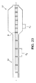
図23を参照すると、マーキングすなわちマーカーMは、カテーテル上の第1の位置のところでのマーキングすなわちマーカーM間の第1の距離D1で位置決めされてもよく、カテーテル上の第2の位置のところでのマーキングすなわちマーカーM間の第2の距離D2で位置決めされてもよい。一例では、バルーン12内のマーキングすなわちマーカーMは、マーキングすなわちマーカー間の第1の距離D1で位置決めされてもよく、一方、カテーテルチューブ14に沿ったバルーン外部の位置でのマーキングすなわちマーカーMは、マーキングすなわちマーカー間の第2の距離D2で位置決めされてもよい。図示する実施形態では、第1の距離D1は、第2の距離D2よりも小さくてもよい。これによって、カテーテル10の近位部分での肉眼での距離測定が可能になり、カテーテル10の遠位部分でのより精細な測定が可能になる。
Referring to FIG. 23, the marking or marker M may be positioned at a first distance D1 between the marking or marker M at a first location on the catheter and at a second location on the catheter. marking That may be positioned at a second distance D 2 between the markers M. In one example, the markings or markers M in the
図24は、さらなる実施形態を示している。この実施形態では、マーキングすなわちマーカーMは、マーキングすなわちマーカーMが互いから非等間隔となるように、それらの間の様々な距離で位置決めされてもよい。図示されるように、第3の距離D3が隣接する第1および第2のマーキングすなわちマーカーM1,M2の間に存在してもよい。さらに、隣接する第2および第3のマーキングすなわちマーカーM2,M3が、第4の距離D4がこれらのマーキングすなわちマーカーM2,M3を離間させるように位置決めされてもよい。第3の距離D3は、第4の距離D4よりも小さくてもよい。一実施形態では、第3の距離D3は、例えば、約5mmであってもよく、第4の距離D4は、例えば、約10mmであってもよい。マーキングすなわちマーカーM間の距離は、カテーテル10の長さに沿って、第3の距離D3と第4の距離D4との間で交互に入れ替わってもよい。マーキングすなわちマーカーM間のこの交互の距離によって、カテーテル10の長さに沿った様々な位置での精細なまたは肉眼での測定が可能になる。
FIG. 24 shows a further embodiment. In this embodiment, the markings or markers M may be positioned at various distances between them such that the markings or markers M are non-equally spaced from each other. As illustrated, the third distance D 3 may be present between the marking of the first and second adjacent That markers M 1, M 2. Further, adjacent second and third markings or markers M 2 , M 3 may be positioned such that a fourth distance D 4 separates these markings or markers M 2 , M 3 . Third distance D 3 may be smaller than the fourth distance D 4. In one embodiment, the third distance D 3 may, for example, may be about 5 mm, a fourth distance D 4 is, for example, it may be about 10 mm. The distance between the markings or markers M may alternate between a third distance D 3 and a fourth distance D 4 along the length of the
図25を参照すると、他の実施形態が開示されており、この実施形態では、マーキングすなわちマーカーM4,M5,M6・・・Mnがカテーテル10に沿って等間隔ではない態様で配置されてもよい。図示されるように、マーキングすなわちマーカーM間の距離は、カテーテル10の遠位端からカテーテル10の近位端まで増大してもよい。例えば、第5の距離D5が、カテーテル10の遠位端のところで、第4および第5のマーキングすなわちマーカーM4,M5間に存在してもよい。同様に、第5の距離D5の近位にある第6の距離D6が、第5および第6のマーキングすなわちマーカーM5,M6間に存在していてもよく、第7の距離D7が、第6および第7のマーキングすなわちマーカーM6,M7間に存在していてもよい。カテーテル10の遠位端からカテーテル10の近位端までの、連続する対の隣接するマーキングすなわちマーカーMの各々の間の距離は、最後の距離Dnを通る前の対のマーキングすなわちマーカーMに対して徐々に増加してもよい。図25の例では、D5<D6<D7・・・Dnである。別の言い方をすれば、マーキングすなわちマーカーM間の距離は、カテーテル10の近位端から遠位端まで連続的に徐々に減少してもよい。隣接するマーキングすなわちマーカーM間の距離のこの減少によって、カテーテル10の遠位端に向けて徐々に、より精細な測定を行うことができる。
Referring to FIG. 25, another embodiment is disclosed, in which the markings or markers M 4 , M 5 , M 6 ... Mn are arranged along the
図26〜28は、治療領域Tを測定して治療バルーン112を治療領域Tまで移送するための、X線不透過性マーキングすなわちマーカーMを有するカテーテル10の使用方法を示している。図26は、カテーテル10のバルーン12を示している。このカテーテル10は、イントロデューサIと呼ばれるデバイスを使用してガイドワイヤ26に沿って血管V内に治療領域T(例えば、病変部位L)まで挿入されている複数のX線不透過性マーキングすなわちマーカーMを備えている。バルーン12は、図27に示すように、血管Vを拡張して病変部位Lを圧縮するように、治療領域Tのところで膨張されてもよい。バルーン12は、使用後に収縮され、取り除かれてもよい。
FIGS. 26-28 illustrate the use of the
カテーテル10に沿った複数のマーキングすなわちマーカーMは、それらの間の既知の距離を区分するように所定の間隔で互いから隔てられていてもよい。これらのマーキングすなわちマーカーMは、治療領域Tの長さを測定するために使用されてもよい。この長さは、図示する実施形態では、病変部位Lの長さに及ぶ距離を構成する。マーキングすなわちマーカーMは、バルーン12の膨張の前および/または後に治療領域Tの長さを測定するために使用されてもよい。治療領域Tの所望のまたは必要な正確な測定のために、ユーザは、目的のために適切な治療バルーン112(これは、測定バルーンとの組み合わせの一部分として用意されてもよい)を選択してもよい。例えば、ユーザは、取得される測定結果に対応する長さを有する作用面を有する治療バルーン112を選択してもよく、あるいは、カテーテル10のマーキングすなわちマーカーに対応するマーキングすなわちマーカーを有する治療のための関連する治療カテーテル110を選択してもよい。
The plurality of markings or markers M along the
次いで、図28に示されるように、選択された治療カテーテル110(これは、カテーテル10と構成が実質的に同じであってもよく、したがって、マッチングX線不透過性マーキングすなわちマーカーを備えていてもよい。このようなマーキングすなわちマーカーには、中央領域と整合させるためのオフセットマーキングが含まれる)は、挿入されて、治療領域Tのところに治療バルーン112を位置決めしてもよい。治療バルーン112は、治療手段(例えば、治療薬(例えば、パクリタキセル、ラパマイシン、ヘパリンなどの薬剤)、ステント、ステントグラフト、または、それらの組み合わせ)を備える作用面W2を備えていてもよい。いくつかの場合では、治療バルーン112は、計測カテーテルのバルーンよりも長くてもよい(後続のインターベンション中に病変部位Lを確実に完全にカバーするように;例えば、第1のバルーンは20mmであってもよく、第2のバルーンは40mmであってもよい)。蛍光透視法によって視認できる体内の共通の位置(例えば骨のランドマーク(例えば、特定の椎骨))に関して、カテーテル10,110の共通の位置決めが行われてもよい。
Then, as shown in FIG. 28, the selected treatment catheter 110 (which may be substantially the same in configuration as the
治療手段を移送する場合には、治療領域Tの全体を治療するために(ただし、治療領域Tよりも広くない範囲の治療を行うために)作用面W2の長さの選択が重要になり得る。治療領域Tの測定距離に対応する作用面W2の長さを有する治療バルーン112は、測定カテーテル10を使用して測定された治療領域Tの長さに基づいて選択されてもよい。このようにして、臨床医は、治療手段の移送が治療領域Tの全体(ただし、他の場所は含まない)に対して所望の態様で達成されることを確実にすることができ、これは、地理的な不整合、治療領域T全体を治療することの失敗、または、治療領域Tの外部での治療薬の過剰摂取を避ける助けとなり得る。したがって、この手順は、潜在的に短くなり、さらなるインターベンションを回避することができる。この測定技術は、必要に応じて、膨張の後に使用されてもよい。
When transferring the treatment means, it is important to select the length of the working surface W 2 in order to treat the entire treatment region T (however, in order to perform treatment in a range not wider than the treatment region T). obtain. A
上記で示唆したように、開示される任意のバルーン12は、1つ以上の治療薬(例えば、ペイロード(薬剤、ステント、または、その両方)または作業器具(カッタ、フォーカスフォースワイヤなど))の形態の治療手段を運んでもよい。例えば、図17に示されるように、定義された作用面W(胴部部位16と端部部位18,20との間の移行部のところのX線不透過性バンド32,34を用意することによる)を有するバルーン12は、血管の内部に適用されるときに所望の治療効果を達成するために構成されるような、そのような薬剤Gでコーティングされた部分を少なくとも備えていてもよい。この治療手段を形成する薬剤Gは、製造工程の一部分(血管系内に挿入するために折り畳む前、または、折り畳みが完了した後が含まれてもよい)としてバルーン12に適用されてもよい。このようにして、臨床医は、血管系内でバルーン12を膨張させて薬剤Gを所望の位置まで移送し、所望の治療(これは、治療計画の一部分を形成してもよい)を提供する前に、蛍光透視法の利益を利用して作用面Wの正確な位置を決定することができる。
As suggested above, any disclosed
カテーテル10(バルーン10またはシャフト24)上のマーキングすなわちマーカー用に本明細書で使用され得るX線不透過性材料の例には、細かく分割されたタングステン、タンタラム、ビスマス、三酸化ビスマス、オキシ塩化ビスマス、次炭酸ビスマス、他のビスマス化合物、硫酸バリウム、スズ、銀、銀化合物、希土類酸化物、および、X線吸収に一般的に使用される他の多くの物質が含まれるが、これらに限定はされない。使用される量は、X線不透過性の所望の程度に応じて分かってもよく、また、任意の形態(例えば、バンド、ホイル、フィルム(埋め込まれたX線不透過性粉末を含む)、転写シール、塗料、コーティングなど)であってもよい。一実施形態では、マーキングすなわちマーカーMは、
ヨウ素、イオプロミド、金属イオン、金、硫酸バリウム、タングステン、三酸化ビスマス、または他の類似の機能材料などのX線不透過性元素が添加されたポリマーを含有していてもよい。X線不透過性材料は、ゲル、粉末、ダスト。粒子、ナノ粒子、液体、塗料、接着剤などの形態で使用されてもよい。マーキングすなわちマーカーを形成するX線不透過性材料は、およそ5ないし95%のX線不透過性、より限定的には、およそ70ないし90%のX線不透過性の任意の値を有していてもよい、
Examples of radiopaque materials that can be used herein for markings or markers on catheter 10 (
It may contain a polymer with added radiopaque elements such as iodine, iopromide, metal ions, gold, barium sulfate, tungsten, bismuth trioxide, or other similar functional materials. Radiopaque materials are gel, powder, and dust. It may be used in the form of particles, nanoparticles, liquids, paints, adhesives and the like. The radiopaque material that forms the marking or marker has an arbitrary value of about 5 to 95% radiopaque, more specifically about 70 to 90% radiopaque. May be,
マーキングすなわちマーカーMは、例えば、白金、イリジウムおよび/または金のマーキングすなわちマーカーなどの金属製マーカーバンドの形態であってもよく、また、かしめ、糊付け、または、他の手段でカテーテル10に取り付けられていてもよい。一実施形態では、カテーテルは、非X線不透過性部位同士の間に分散された熱接合されたX線不透過性部位を備えていてもよい。さらなる実施形態では、マーキングすなわちマーカーMは、カテーテル10に適用されたX線不透過性テープまたはフィルムを備えていてもよい。マーキングすなわちマーカーMを形成するために、X線不透過性インクが使用されてもよい。バンドが上述され、図示されたが、マーキングすなわちマーカーMは、記号(数、文字)幾何学的形状(グラデーションライン、ハッシュマーク、ドットなど)、または、これらの1つ以上の組み合わせの形態であってもよい。上述のマーキングすなわちマーカー化合物は、医薬に現在使用されている様々なX線不透過性マーキングすなわちマーカーの例であるが、マーキングすなわちマーカーは、
使用中に血管系内の特定の位置を可視化することができる任意の技術を含んでいてもよい。
The marking or marker M may be in the form of a metallic marker band such as, for example, platinum, iridium and / or gold markings or markers and is attached to the
Any technique capable of visualizing a specific location within the vasculature during use may be included.
本開示は発明の概念を説明するためにいくつかの実施形態を提示したが、添付の特許請求の範囲に定義されるように、本発明の領域および範囲から逸脱することなく、説明された実施形態に対して多くの修正形態、変形形態および変更が可能である。例えば、様々な実施形態で提示される任意の範囲および数値は、公差、環境要因の変化、材料の品質、構造の修正、および、バルーンの形状に起因して変わるので、およそのものであると捉えることができ、「約」との用語は、そのような要因のために、関連する値が最小限変わり得ることを意味している。また、図面(発明の概念を示しているが)は、縮尺通りではなく、いかなる特定のサイズまたは寸法に限定されるべきではない。したがって、本開示が、説明された実施形態に限定されるものではなく、次の特許請求の範囲の言語によって定義される最大の範囲およびその均等物有していることが意図されている。 While this disclosure has presented several embodiments to illustrate the concepts of the invention, the described implementations may be made without departing from the scope and scope of the invention as defined in the appended claims. Many modifications, variations, and changes to the form are possible. For example, any ranges and values presented in various embodiments are approximate because they vary due to tolerances, changes in environmental factors, material quality, structural modifications, and balloon shape. The term “about” means that the associated value can vary minimally due to such factors. Also, the drawings (though showing the concept of the invention) are not to scale and should not be limited to any particular size or dimension. Accordingly, the present disclosure is not intended to be limited to the described embodiments, but is intended to have the largest scope defined by the language of the following claims and equivalents thereof.
10…測定カテーテル
10…カテーテル
11…遠位部分
12…バルーン
14…カテーテルチューブ
14a…側方開口
15a…近位端
15b…遠位端
16…胴部部位(中間部位)
17…膨張内腔
18,20…コーン部位(円錐部分)
23…ガイドワイヤ内腔
24…シャフト
25…第1のポート
26…ガイドワイヤ
27…コネクタ
28…バルーン壁
29…第2のポート
32…近位バンド
34…遠位バンド
36…マーキング
110…治療カテーテル
112…治療バルーン
DESCRIPTION OF
17 ...
23 ...
Claims (30)
シャフトと、
前記シャフトに固定される遠位端を有するとともに内部を有する膨張可能なバルーンと、
前記バルーンの前記内部において前記シャフト上に前記カテーテルの長手方向軸線に沿って間隔が隔てられた少なくとも3つのX線不透過性マーキングと
を備え、
第1のX線不透過性マーキングを隣接する第2のX線不透過性マーキングから離間させる第1の距離は、前記第2のX線不透過性マーキングを隣接する第3のX線不透過性マーキングから離間させる第2の距離とは異なっており、
前記バルーンは、非膨張中央位置と膨張中央位置とを備え、
前記シャフトは、前記非膨張中央位置に対してオフセットされた位置に位置決めされた少なくとも1つのX線不透過性マーキングを備え、
前記バルーンの膨張時に、前記少なくとも1つのX線不透過性マーキングは、前記膨張中央位置と実質的に整合し、
前記第1のX線不透過性マーキングは、非膨張状態における前記バルーンの作用面の1つの端部に対応する位置に設けられた
バルーンカテーテル。 A balloon catheter for insertion into a blood vessel to treat a treatment area,
A shaft,
An inflatable balloon having a distal end secured to the shaft and having an interior;
At least three radiopaque markings spaced along the longitudinal axis of the catheter on the shaft within the interior of the balloon;
The first distance separating the first radiopaque marking from the adjacent second radiopaque marking is the third radiopaque mark adjacent to the second radiopaque marking. Different from the second distance away from the sex marking,
The balloon comprises a non-inflated central position and an inflated central position,
The shaft comprises at least one radiopaque marking positioned at a position offset relative to the non-inflatable central position;
When the balloon is inflated, the at least one radiopaque marking is substantially aligned with the center of inflation ,
The first radiopaque marking is a balloon catheter provided at a position corresponding to one end of the working surface of the balloon in a non-inflated state .
前記カテーテルの前記シャフトは、さらに、ガイドワイヤ内腔を形成する内側チューブ状部材を備え、
前記内側チューブ状部材は、少なくとも3つのX線不透過性マーキングを備える
バルーンカテーテル。 The balloon catheter according to claim 1,
The shaft of the catheter further comprises an inner tubular member forming a guidewire lumen;
The inner tubular member comprises at least three radiopaque markings balloon catheter.
前記シャフトは、前記第1のX線不透過性マーキングおよび前記第2のX線不透過性マーキングの少なくとも一方を有する外壁を備える
バルーンカテーテル。 The balloon catheter according to claim 1 or 2,
The shaft includes an outer wall having at least one of the first radiopaque marking and the second radiopaque marking.
前記第1の距離は、前記第2の距離よりも小さく、
前記長手方向軸線に沿って、前記第1のX線不透過性マーキングは、前記第2のX線不透過性マーキングに対して遠位側にあり、前記第2のX線不透過性マーキングは、前記第3のX線不透過性マーキングに対して遠位側にある
バルーンカテーテル。 The balloon catheter according to any one of claims 1 to 3,
The first distance is smaller than the second distance;
Along the longitudinal axis, the first radiopaque marking is distal to the second radiopaque marking and the second radiopaque marking is A balloon catheter distal to the third radiopaque marking.
前記少なくとも3つのX線不透過性マーキングは、複数の隣接する対を備えるパターンで配列され、
前記隣接する対は、前記第1の距離および前記第2の距離によって交互に間隔が隔てられている
バルーンカテーテル。 The balloon catheter according to any one of claims 1 to 4,
The at least three radiopaque markings are arranged in a pattern comprising a plurality of adjacent pairs;
The adjacent pairs are alternately spaced by the first distance and the second distance balloon catheter.
前記X線不透過性マーキングは、前記カテーテル上の遠位位置から前記カテーテル上の近位位置まで互いから徐々に距離が大きくなるように間隔が隔てられた隣接するX線不透過性マーキングを備えるパターンで配列されている
バルーンカテーテル。 The balloon catheter according to any one of claims 1 to 5,
The radiopaque marking comprises adjacent radiopaque markings that are spaced apart from one another from a distal location on the catheter to a proximal location on the catheter. Balloon catheters arranged in a pattern.
前記シャフト上の前記第3のX線不透過性マーキングは、前記非膨張状態における前記バルーンの前記作用面の他の端部に対応する位置に設けられた
バルーンカテーテル。 The balloon catheter according to claim 1 ,
The third radiopaque marking on the shaft is provided at a position corresponding to the other end of the working surface of the balloon in the non-inflated state .
前記オフセットされた位置は、前記非膨張中央位置から近位方向に間隔が隔てられている
バルーンカテーテル。 The balloon catheter according to any one of claims 1 to 7 ,
The offset position is spaced proximally from the non-inflated central position balloon catheter.
前記オフセットされた位置は、前記非膨張中央位置から遠位方向に間隔が隔てられている
バルーンカテーテル。 The balloon catheter according to any one of claims 1 to 7 ,
The offset position is spaced distally from the non-inflated central position.
前記オフセットされた位置は、膨張状態にある前記バルーンの前記遠位端と近位端との間の長さの約1ないし15%の距離だけ前記非膨張中央位置から間隔が隔てられている
バルーンカテーテル。 The balloon catheter according to any one of claims 1 to 7 ,
The offset position is spaced from the non-inflated central position by a distance of about 1 to 15% of the length between the distal and proximal ends of the balloon in an inflated state. catheter.
さらに、前記バルーンの外面に少なくとも1つのX線不透過性マーキングを備える
バルーンカテーテル。 The balloon catheter according to any one of claims 1 to 11,
A balloon catheter further comprising at least one radiopaque marking on the outer surface of the balloon.
前記外部のX線不透過性マーキングは、前記シャフト上に配置された
バルーンカテーテル。 The balloon catheter according to claim 11 ,
The external radiopaque marking is a balloon catheter disposed on the shaft.
さらに、前記バルーンに膨張流体を供給するための膨張内腔を形成する外側チューブ状シャフトを備え、
前記外部のX線不透過性マーキングは、前記外側チューブ状シャフト上に配置された
バルーンカテーテル。 The balloon catheter according to claim 11 ,
And further comprising an outer tubular shaft forming an inflation lumen for supplying inflation fluid to the balloon;
The external radiopaque marking is a balloon catheter disposed on the outer tubular shaft.
さらに、前記バルーンの外面に複数のX線不透過性マーキングを備え、
前記複数の外部のX線不透過性マーキングは、等間隔に間隔が隔てられている
バルーンカテーテル。 The balloon catheter according to any one of claims 1 to 13 ,
In addition, the outer surface of the balloon comprises a plurality of radiopaque markings,
The plurality of external radiopaque markings are spaced equidistantly from the balloon catheter.
さらに、前記バルーンの外面に複数のX線不透過性マーキングを備え、
前記複数の外部のX線不透過性マーキングは、不規則に間隔が隔てられている
バルーンカテーテル。 The balloon catheter according to any one of claims 1 to 14 ,
In addition, the outer surface of the balloon comprises a plurality of radiopaque markings,
The plurality of external radiopaque markings are irregularly spaced balloon catheter.
前記マーキングは、少なくとも部分的にX線不透過性材料から形成されたバンドを備える
バルーンカテーテル。 The balloon catheter according to any one of claims 1 to 15 ,
The marking comprises a band formed at least in part from a radiopaque material balloon catheter.
シャフトと、
前記シャフトに固定される遠位端を有するとともに内部を有する膨張可能なバルーンと、
前記シャフト上で前記カテーテルの長手方向軸線に沿って延在するとともに、前記バルーンの前記内部に配置された少なくとも3つのX線不透過性マーキングと
を備え、
第1のX線不透過性マーキングを第2のX線不透過性マーキングから離間させる非X線不透過性材料の第1の量は、前記第2のX線不透過性マーキングを第3のX線不透過性マーキングから離間させる非X線不透過性材料の第2の量とは異なっており、
前記バルーンは、非膨張中央位置と膨張中央位置とを備え、
前記シャフトは、前記非膨張中央位置に対してオフセットされた位置に位置決めされた少なくとも1つのX線不透過性マーキングを備え、
前記バルーンの膨張時に、前記少なくとも1つのX線不透過性マーキングは、前記膨張中央位置と実質的に整合し、
前記第1のX線不透過性マーキングは、非膨張状態における前記バルーンの作用面の1つの端部に対応する位置に設けられた
バルーンカテーテル。 A balloon catheter for insertion into a blood vessel to treat a treatment area,
A shaft,
An inflatable balloon having a distal end secured to the shaft and having an interior;
Extending along the longitudinal axis of the catheter on the shaft and comprising at least three radiopaque markings disposed in the interior of the balloon;
A first amount of non-radiopaque material that separates the first radiopaque marking from the second radiopaque marking causes the second radiopaque marking to pass through the third radiopaque marking. Different from the second amount of non-radiopaque material spaced from the radiopaque marking;
The balloon comprises a non-inflated central position and an inflated central position,
The shaft comprises at least one radiopaque marking positioned at a position offset relative to the non-inflatable central position;
When the balloon is inflated, the at least one radiopaque marking is substantially aligned with the center of inflation ,
The first radiopaque marking is a balloon catheter provided at a position corresponding to one end of the working surface of the balloon in a non-inflated state .
細長いチューブ状のシャフトと、
前記シャフトによって支持され、前記シャフトに固定される遠位端を有するとともに、非膨張中央位置と膨張中央位置とを有する膨張可能なバルーンと
を備え、
前記シャフトは、前記非膨張中央位置に対してオフセットされた位置に位置決めされた少なくとも1つの第1のX線不透過性マーキングを備え、
前記バルーンの膨張時に、前記少なくとも1つの第1のX線不透過性マーキングは、前記膨張中央位置と実質的に整合し、
前記シャフトは、さらに、非膨張状態における前記バルーンの作用面の1つの端部に対応する位置に設けられた第2のX線不透過性マーキングを備える
バルーンカテーテル。 A balloon catheter,
An elongated tubular shaft;
An inflatable balloon supported by the shaft, having a distal end fixed to the shaft, and having a non-inflatable central position and an inflatable central position;
The shaft comprises at least one first radiopaque marking positioned at a position offset relative to the non-inflatable central position;
Upon inflation of the balloon, the at least one first radiopaque marking is substantially aligned with the inflation center position ;
The shaft further comprises a second radiopaque marking provided at a position corresponding to one end of the working surface of the balloon in a non-inflated state .
前記第2のX線不透過性マーキングは、前記バルーン上に設けられる
バルーンカテーテル。 The balloon catheter according to claim 18 ,
The second radiopaque marking is provided on the balloon.
前記第2のX線不透過性マーキングは、前記作用面の一方の端部に隣接する前記バルーンの幅狭の端部部位に沿って設けられる
バルーンカテーテル。 The balloon catheter according to claim 18 ,
The second radiopaque marking is provided along a narrow end portion of the balloon adjacent to one end of the working surface.
前記第2のX線不透過性マーキングは、前記作用面の一方の端部に対応する位置で前記シャフト上に設けられる
バルーンカテーテル。 The balloon catheter according to claim 18 ,
The second radiopaque marking is provided on the shaft at a position corresponding to one end of the working surface.
さらに、前記非膨張状態における前記バルーンの前記作用面の他の端部に対応する位置で前記シャフト上に設けられた第3のX線不透過性マーキングを備える
バルーンカテーテル。 The balloon catheter according to any one of claims 18 to 21 ,
A balloon catheter further comprising a third radiopaque marking provided on the shaft at a position corresponding to the other end of the working surface of the balloon in the non-inflated state .
単数または複数の前記X線不透過性マーキングは、少なくとも部分的にX線不透過性材料から形成されたバンドを備える
バルーンカテーテル。 The balloon catheter according to any one of claims 18 to 21 ,
The one or more radiopaque markings comprise a band formed at least in part from a radiopaque material.
前記オフセットされた位置は、前記非膨張中央位置から近位方向に間隔が隔てられている
バルーンカテーテル。 The balloon catheter according to any one of claims 18 to 21 ,
The offset position is spaced proximally from the non-inflated central position balloon catheter.
前記オフセットされた位置は、前記非膨張中央位置から遠位方向に間隔が隔てられている
バルーンカテーテル。 The balloon catheter according to any one of claims 18 to 21 ,
The offset position is spaced distally from the non-inflated central position.
前記オフセットされた位置は、膨張状態にある前記バルーンの前記遠位端と近位端との間の長さの約1ないし15%の距離だけ前記非膨張中央位置から間隔が隔てられている
バルーンカテーテル。 The balloon catheter according to any one of claims 18 to 21 ,
The offset position is spaced from the non-inflated central position by a distance of about 1 to 15% of the length between the distal and proximal ends of the balloon in an inflated state. catheter.
前記第1のX線不透過性マーキングの位置と実質的に一致するオフセットされた第2のX線不透過性マーキングを備える第2のバルーンカテーテルと組み合わせられた
バルーンカテーテル。 A balloon catheter according to any one of claims 18 to 26 , wherein
A balloon catheter in combination with a second balloon catheter comprising an offset second radiopaque marking that substantially coincides with the position of the first radiopaque marking.
前記シャフトは、ガイドワイヤ内腔を備える
バルーンカテーテル。 A balloon catheter according to any one of claims 18 to 27 ,
The shaft comprises a guide wire lumen Balloon catheter.
前記少なくとも1つの第1のX線不透過性マーキングは、前記膨張中央位置と整合する
バルーンカテーテル。 A balloon catheter according to any one of claims 18 to 28 , comprising:
The at least one first radiopaque marking is aligned with the inflated central position of a balloon catheter.
前記バルーンは、薬剤を備える
バルーンカテーテル。 A balloon catheter according to any one of claims 18 to 29 , wherein
The balloon comprises a drug balloon catheter.
Applications Claiming Priority (5)
| Application Number | Priority Date | Filing Date | Title |
|---|---|---|---|
| US201261675168P | 2012-07-24 | 2012-07-24 | |
| US61/675,168 | 2012-07-24 | ||
| US201361788938P | 2013-03-15 | 2013-03-15 | |
| US61/788,938 | 2013-03-15 | ||
| PCT/US2013/051863 WO2014018659A2 (en) | 2012-07-24 | 2013-07-24 | Balloon catheter with enhanced locatability |
Publications (3)
| Publication Number | Publication Date |
|---|---|
| JP2015527123A JP2015527123A (en) | 2015-09-17 |
| JP2015527123A5 JP2015527123A5 (en) | 2016-06-16 |
| JP6235011B2 true JP6235011B2 (en) | 2017-11-22 |
Family
ID=48916255
Family Applications (1)
| Application Number | Title | Priority Date | Filing Date |
|---|---|---|---|
| JP2015524424A Active JP6235011B2 (en) | 2012-07-24 | 2013-07-24 | Balloon catheter with improved positioning performance |
Country Status (12)
| Country | Link |
|---|---|
| US (4) | US20150165170A1 (en) |
| EP (2) | EP3064249A3 (en) |
| JP (1) | JP6235011B2 (en) |
| KR (1) | KR102143444B1 (en) |
| CN (3) | CN110227206B (en) |
| AU (1) | AU2013295789B2 (en) |
| BR (1) | BR112015001497B1 (en) |
| CA (1) | CA2878578C (en) |
| CO (1) | CO7240403A2 (en) |
| MX (1) | MX362797B (en) |
| NZ (1) | NZ704015A (en) |
| WO (1) | WO2014018659A2 (en) |
Families Citing this family (22)
| Publication number | Priority date | Publication date | Assignee | Title |
|---|---|---|---|---|
| EP3064249A3 (en) * | 2012-07-24 | 2016-09-14 | Clearstream Technologies Limited | Balloon catheter with enhanced locatability |
| WO2014102608A2 (en) | 2012-12-31 | 2014-07-03 | Clearsteam Technologies Limited | Catheter with markings to facilitate alignment |
| EP3107613A2 (en) * | 2014-02-17 | 2016-12-28 | Clearstream Technologies Limited | Anchored guidewire with markings to facilitate alignment |
| RU2019112030A (en) * | 2014-03-31 | 2019-05-06 | Клиарстрим Текнолоджис Лимитед | CATHETERS TO REDUCE THE DEGREE OF THE USE OF X-RAY AGAINS WHEN PERFORMING ENDOVASCULAR OPERATIONS |
| US20150327871A1 (en) * | 2014-05-15 | 2015-11-19 | Abbott Cardiovascular Systems, Inc. | Methods, systems, and devices for targeting a radial access puncture site |
| US20160235530A1 (en) * | 2015-02-18 | 2016-08-18 | St. Jude Medical, Cardiology Division, Inc. | Introducer sheath for transcatheter heart valve delivery |
| US10940299B2 (en) | 2015-08-10 | 2021-03-09 | Gyms Acmi, Inc. | Center marker for dilatation balloon |
| US10499892B2 (en) * | 2015-08-11 | 2019-12-10 | The Spectranetics Corporation | Temporary occlusion balloon devices and methods for preventing blood flow through a vascular perforation |
| US11071576B2 (en) * | 2015-10-27 | 2021-07-27 | Spinal Simplicity, Llc | Flexible guide wire with tantalum marker |
| US11134917B2 (en) | 2015-12-14 | 2021-10-05 | Koninklijke Philips N.V. | Imaging system and method of determining a translation speed of a catheter |
| CN109069796B (en) * | 2016-02-10 | 2021-07-30 | 微仙美国有限公司 | Intravascular treatment site access |
| MX2018010906A (en) | 2016-03-11 | 2019-05-20 | Laborie Medical Tech Corp | Pressure catheter device. |
| DE102016108783A1 (en) * | 2016-05-12 | 2017-11-16 | Biotronik Ag | Balloon catheter with radiopaque marker |
| US11660121B2 (en) | 2016-10-18 | 2023-05-30 | East End Medical Llc | Transseptal insertion device |
| JP6564757B2 (en) * | 2016-11-11 | 2019-08-21 | 日本ライフライン株式会社 | Treatment device |
| KR20200030610A (en) * | 2017-08-10 | 2020-03-20 | 베이리스 메디컬 컴퍼니 아이엔씨. | Heat exchange and temperature sensing devices and methods of use |
| JP7470138B2 (en) | 2019-06-11 | 2024-04-17 | イースト エンド メディカル エルエルシー | Directional balloon transseptal insertion device for medical procedures including an improved transseptal piercing system having a piercing balloon seal - Patents.com |
| CN211884905U (en) | 2019-08-22 | 2020-11-10 | 贝克顿·迪金森公司 | Balloon dilatation catheter and balloon thereof |
| MX2022003360A (en) | 2019-09-20 | 2022-05-26 | East End Medical Llc | Directional balloon transseptal insertion device for medical procedures with improved transseptal puncture system with puncture member balloon seal. |
| MX2022004010A (en) | 2019-10-04 | 2022-05-19 | East End Medical Llc | Directional balloon transseptal insertion device for medical procedures with improved handle. |
| CN111467658A (en) * | 2020-05-15 | 2020-07-31 | 四川大学华西医院 | Balloon catheter for transjugular intrahepatic portosystemic shunt |
| JP2023540911A (en) * | 2020-08-31 | 2023-09-27 | バード・ペリフェラル・バスキュラー・インコーポレーテッド | Bifunctional balloon catheter for passing through lesions and performing percutaneous angioplasty |
Family Cites Families (51)
| Publication number | Priority date | Publication date | Assignee | Title |
|---|---|---|---|---|
| US4637396A (en) * | 1984-10-26 | 1987-01-20 | Cook, Incorporated | Balloon catheter |
| US4744366A (en) * | 1986-09-10 | 1988-05-17 | Jang G David | Concentric independently inflatable/deflatable multiple diameter balloon angioplasty catheter systems and method of use |
| US4748982A (en) * | 1987-01-06 | 1988-06-07 | Advanced Cardiovascular Systems, Inc. | Reinforced balloon dilatation catheter with slitted exchange sleeve and method |
| US4793359A (en) * | 1987-04-24 | 1988-12-27 | Gv Medical, Inc. | Centering balloon structure for transluminal angioplasty catheter |
| US4917666A (en) * | 1988-11-14 | 1990-04-17 | Medtronic Versaflex, Inc. | Steerable thru-lumen catheter |
| US4986830A (en) * | 1989-09-22 | 1991-01-22 | Schneider (U.S.A.) Inc. | Valvuloplasty catheter with balloon which remains stable during inflation |
| US5209730A (en) * | 1989-12-19 | 1993-05-11 | Scimed Life Systems, Inc. | Method for placement of a balloon dilatation catheter across a stenosis and apparatus therefor |
| US5135486A (en) * | 1990-08-31 | 1992-08-04 | Endosonics Corporation | Self-venting balloon dilitation catheter |
| US5766151A (en) * | 1991-07-16 | 1998-06-16 | Heartport, Inc. | Endovascular system for arresting the heart |
| US5316016A (en) * | 1992-07-07 | 1994-05-31 | Scimed Life Systems, Inc. | Imaging balloon catheter and methods for use and manufacture |
| JP3403233B2 (en) * | 1994-01-20 | 2003-05-06 | テルモ株式会社 | Balloon catheter |
| US5549551A (en) * | 1994-12-22 | 1996-08-27 | Advanced Cardiovascular Systems, Inc. | Adjustable length balloon catheter |
| US5549552A (en) * | 1995-03-02 | 1996-08-27 | Scimed Life Systems, Inc. | Balloon dilation catheter with improved pushability, trackability and crossability |
| US5840008A (en) * | 1995-11-13 | 1998-11-24 | Localmed, Inc. | Radiation emitting sleeve catheter and methods |
| US6746425B1 (en) | 1996-06-14 | 2004-06-08 | Futuremed Interventional | Medical balloon |
| US6692483B2 (en) * | 1996-11-04 | 2004-02-17 | Advanced Stent Technologies, Inc. | Catheter with attached flexible side sheath |
| US5779731A (en) * | 1996-12-20 | 1998-07-14 | Cordis Corporation | Balloon catheter having dual markers and method |
| US5876344A (en) * | 1997-12-09 | 1999-03-02 | Endosonics Corporation | Modular imaging/treatment catheter assembly and method |
| US6344045B1 (en) * | 1998-04-21 | 2002-02-05 | Advanced Cardiovascular Systems, Inc. | Sizing and therapeutic catheter with sheath |
| JP2000107293A (en) * | 1998-10-08 | 2000-04-18 | Terumo Corp | Vasodilating instrument |
| US6977103B2 (en) * | 1999-10-25 | 2005-12-20 | Boston Scientific Scimed, Inc. | Dimensionally stable balloons |
| AU1013001A (en) * | 1999-10-26 | 2001-05-08 | Cedara Software Corp. | Catheter with radiopaque markers for 3d position tracking |
| US6520934B1 (en) * | 1999-12-29 | 2003-02-18 | Advanced Cardiovascular Systems, Inc. | Catheter assemblies with flexible radiopaque marker |
| WO2001095794A1 (en) * | 2000-06-12 | 2001-12-20 | Cordis Corporation | Vascular guidewire for magnetic resonance and/or fluoroscopy |
| US6656211B1 (en) * | 2000-10-26 | 2003-12-02 | Scimed Life Systems, Inc. | Stent delivery system with improved tracking |
| US6761708B1 (en) * | 2000-10-31 | 2004-07-13 | Advanced Cardiovascular Systems, Inc. | Radiopaque marker for a catheter and method of making |
| US7322958B2 (en) * | 2001-12-27 | 2008-01-29 | Wholey Mark H | Apparatus for thromboembolic protection |
| US7653438B2 (en) * | 2002-04-08 | 2010-01-26 | Ardian, Inc. | Methods and apparatus for renal neuromodulation |
| US20040267195A1 (en) * | 2003-06-24 | 2004-12-30 | Arnoldo Currlin | Catheter balloon having visible marker |
| US20050065434A1 (en) * | 2003-09-22 | 2005-03-24 | Bavaro Vincent P. | Polymeric marker with high radiopacity for use in medical devices |
| US20050064223A1 (en) * | 2003-09-22 | 2005-03-24 | Bavaro Vincent Peter | Polymeric marker with high radiopacity |
| US7198632B2 (en) * | 2004-03-02 | 2007-04-03 | Boston Scientific Scimed, Inc. | Occlusion balloon catheter with longitudinally expandable balloon |
| US7803150B2 (en) * | 2004-04-21 | 2010-09-28 | Acclarent, Inc. | Devices, systems and methods useable for treating sinusitis |
| JP4605581B2 (en) * | 2004-05-28 | 2011-01-05 | フィルメック株式会社 | Balloon catheter |
| US7354419B2 (en) | 2004-10-15 | 2008-04-08 | Futuremed Interventional, Inc. | Medical balloon having strengthening rods |
| US7309324B2 (en) | 2004-10-15 | 2007-12-18 | Futuremed Interventional, Inc. | Non-compliant medical balloon having an integral woven fabric layer |
| US7682335B2 (en) | 2004-10-15 | 2010-03-23 | Futurematrix Interventional, Inc. | Non-compliant medical balloon having an integral non-woven fabric layer |
| US20080188803A1 (en) * | 2005-02-03 | 2008-08-07 | Jang G David | Triple-profile balloon catheter |
| US20070100280A1 (en) * | 2005-03-31 | 2007-05-03 | Van Sloten Leonard A | Catheter with balloon material having visual marker |
| US7195612B2 (en) * | 2005-03-31 | 2007-03-27 | Gordis Corporation | Esophageal balloon catheter with visual marker |
| US20090270801A1 (en) * | 2005-04-06 | 2009-10-29 | Kaneka Corporation | Catheter |
| WO2007007560A1 (en) * | 2005-07-08 | 2007-01-18 | Goodman Co., Ltd. | Catheter |
| US8961491B2 (en) * | 2006-04-21 | 2015-02-24 | Bayer Medical Care Inc | Catheters and related equipment |
| US20080097404A1 (en) * | 2006-08-16 | 2008-04-24 | Abbott Laboratories | Catheter having markers to indicate rotational orientation |
| ITNA20060112A1 (en) * | 2006-09-08 | 2008-03-09 | Ciro Indolfi | CABLE CATHETER WITH MORE THAN TWO RADIO-OPAQUE MARKERS FOR THE MEASUREMENT OF ARTERIAL SEGMENTS IN ASSOCIATION WITH THE USE OF X-RAYS. |
| US20080255447A1 (en) * | 2007-04-16 | 2008-10-16 | Henry Bourang | Diagnostic catheter |
| US8617114B2 (en) * | 2007-07-13 | 2013-12-31 | Abbott Cardiovascular Systems Inc. | Drug coated balloon catheter |
| US8690823B2 (en) * | 2007-07-13 | 2014-04-08 | Abbott Cardiovascular Systems Inc. | Drug coated balloon catheter |
| US8114429B2 (en) * | 2008-09-15 | 2012-02-14 | Cv Ingenuity Corp. | Local delivery of water-soluble or water-insoluble therapeutic agents to the surface of body lumens |
| JP2013022347A (en) * | 2011-07-25 | 2013-02-04 | Goodman Co Ltd | Method for manufacturing balloon catheter |
| EP3064249A3 (en) * | 2012-07-24 | 2016-09-14 | Clearstream Technologies Limited | Balloon catheter with enhanced locatability |
-
2013
- 2013-07-24 EP EP16166827.2A patent/EP3064249A3/en active Pending
- 2013-07-24 US US14/403,886 patent/US20150165170A1/en not_active Abandoned
- 2013-07-24 WO PCT/US2013/051863 patent/WO2014018659A2/en active Application Filing
- 2013-07-24 CN CN201910652381.4A patent/CN110227206B/en active Active
- 2013-07-24 CN CN201380037687.XA patent/CN104470576B/en active Active
- 2013-07-24 NZ NZ704015A patent/NZ704015A/en unknown
- 2013-07-24 KR KR1020157001759A patent/KR102143444B1/en active IP Right Grant
- 2013-07-24 CA CA2878578A patent/CA2878578C/en active Active
- 2013-07-24 BR BR112015001497-6A patent/BR112015001497B1/en active IP Right Grant
- 2013-07-24 CN CN201811560348.0A patent/CN109675175B/en active Active
- 2013-07-24 EP EP13745299.1A patent/EP2877229B1/en active Active
- 2013-07-24 AU AU2013295789A patent/AU2013295789B2/en active Active
- 2013-07-24 JP JP2015524424A patent/JP6235011B2/en active Active
- 2013-07-24 MX MX2015000526A patent/MX362797B/en active IP Right Grant
-
2014
- 2014-12-10 CO CO14271665A patent/CO7240403A2/en unknown
-
2017
- 2017-02-24 US US15/441,895 patent/US10384035B2/en active Active
-
2019
- 2019-04-17 US US16/387,122 patent/US11202884B2/en active Active
-
2021
- 2021-12-16 US US17/553,255 patent/US20220118223A1/en active Pending
Also Published As
| Publication number | Publication date |
|---|---|
| CN104470576B (en) | 2019-07-19 |
| CN104470576A (en) | 2015-03-25 |
| AU2013295789B2 (en) | 2018-05-24 |
| US20190240454A1 (en) | 2019-08-08 |
| US20170173302A1 (en) | 2017-06-22 |
| KR102143444B1 (en) | 2020-08-12 |
| EP3064249A2 (en) | 2016-09-07 |
| WO2014018659A3 (en) | 2014-04-17 |
| KR20150037872A (en) | 2015-04-08 |
| US10384035B2 (en) | 2019-08-20 |
| AU2013295789A1 (en) | 2015-02-12 |
| BR112015001497A2 (en) | 2017-07-04 |
| BR112015001497B1 (en) | 2021-03-09 |
| CA2878578C (en) | 2021-04-20 |
| CN109675175A (en) | 2019-04-26 |
| CO7240403A2 (en) | 2015-04-17 |
| EP2877229A2 (en) | 2015-06-03 |
| US20220118223A1 (en) | 2022-04-21 |
| CN110227206A (en) | 2019-09-13 |
| EP2877229B1 (en) | 2018-09-12 |
| CN110227206B (en) | 2022-04-22 |
| MX2015000526A (en) | 2015-10-12 |
| EP3064249A3 (en) | 2016-09-14 |
| CN109675175B (en) | 2022-09-09 |
| US20150165170A1 (en) | 2015-06-18 |
| JP2015527123A (en) | 2015-09-17 |
| WO2014018659A2 (en) | 2014-01-30 |
| US11202884B2 (en) | 2021-12-21 |
| CA2878578A1 (en) | 2014-01-30 |
| MX362797B (en) | 2019-02-12 |
| NZ704015A (en) | 2016-09-30 |
Similar Documents
| Publication | Publication Date | Title |
|---|---|---|
| JP6235011B2 (en) | Balloon catheter with improved positioning performance | |
| EP2822628B1 (en) | Balloon catheter with expandable shaft | |
| EP2822635B1 (en) | Medical balloon with radiopaque identifier for precisely identifying the working surface | |
| EP3524312B1 (en) | Medical balloon with radiopaque end portion for precisely identifying a working surface location | |
| US10994096B2 (en) | Balloon catheter with floating hub | |
| JP6310403B2 (en) | Medical balloon with co-extruded radiopaque part | |
| BR112015013364B1 (en) | apparatus for treating a treatment area in a vasculature and method of assembling a set that includes a catheter that includes a balloon | |
| JP2015512694A (en) | Medical balloon having a radiopaque insert for accurately identifying the location of the working surface | |
| EP2822631B1 (en) | Medical balloon including a radiopaque wire for precisely identifying a working surface location |
Legal Events
| Date | Code | Title | Description |
|---|---|---|---|
| A521 | Request for written amendment filed |
Free format text: JAPANESE INTERMEDIATE CODE: A523 Effective date: 20160419 |
|
| A621 | Written request for application examination |
Free format text: JAPANESE INTERMEDIATE CODE: A621 Effective date: 20160419 |
|
| A131 | Notification of reasons for refusal |
Free format text: JAPANESE INTERMEDIATE CODE: A131 Effective date: 20170201 |
|
| A977 | Report on retrieval |
Free format text: JAPANESE INTERMEDIATE CODE: A971007 Effective date: 20170131 |
|
| A521 | Request for written amendment filed |
Free format text: JAPANESE INTERMEDIATE CODE: A523 Effective date: 20170411 |
|
| TRDD | Decision of grant or rejection written | ||
| A01 | Written decision to grant a patent or to grant a registration (utility model) |
Free format text: JAPANESE INTERMEDIATE CODE: A01 Effective date: 20170926 |
|
| A61 | First payment of annual fees (during grant procedure) |
Free format text: JAPANESE INTERMEDIATE CODE: A61 Effective date: 20171025 |
|
| R150 | Certificate of patent or registration of utility model |
Ref document number: 6235011 Country of ref document: JP Free format text: JAPANESE INTERMEDIATE CODE: R150 |
|
| R250 | Receipt of annual fees |
Free format text: JAPANESE INTERMEDIATE CODE: R250 |
|
| R250 | Receipt of annual fees |
Free format text: JAPANESE INTERMEDIATE CODE: R250 |
|
| R250 | Receipt of annual fees |
Free format text: JAPANESE INTERMEDIATE CODE: R250 |
|
| R250 | Receipt of annual fees |
Free format text: JAPANESE INTERMEDIATE CODE: R250 |