JP6234561B2 - Method for controlling the hydraulic pressure of a fluid transmission - Google Patents
Method for controlling the hydraulic pressure of a fluid transmission Download PDFInfo
- Publication number
- JP6234561B2 JP6234561B2 JP2016519361A JP2016519361A JP6234561B2 JP 6234561 B2 JP6234561 B2 JP 6234561B2 JP 2016519361 A JP2016519361 A JP 2016519361A JP 2016519361 A JP2016519361 A JP 2016519361A JP 6234561 B2 JP6234561 B2 JP 6234561B2
- Authority
- JP
- Japan
- Prior art keywords
- pressure
- control
- signal
- control unit
- power switch
- Prior art date
- Legal status (The legal status is an assumption and is not a legal conclusion. Google has not performed a legal analysis and makes no representation as to the accuracy of the status listed.)
- Active
Links
- 230000005540 biological transmission Effects 0.000 title claims description 56
- 238000000034 method Methods 0.000 title claims description 39
- 239000012530 fluid Substances 0.000 title claims description 28
- 230000001276 controlling effect Effects 0.000 claims description 14
- 238000005259 measurement Methods 0.000 claims description 6
- 230000001105 regulatory effect Effects 0.000 claims description 6
- 238000012545 processing Methods 0.000 claims description 4
- 238000004891 communication Methods 0.000 claims description 3
- 230000001419 dependent effect Effects 0.000 claims description 2
- 238000010586 diagram Methods 0.000 description 2
- 238000005265 energy consumption Methods 0.000 description 2
- 239000010720 hydraulic oil Substances 0.000 description 2
- 230000006866 deterioration Effects 0.000 description 1
- 238000009434 installation Methods 0.000 description 1
- 239000003921 oil Substances 0.000 description 1
Images
Classifications
-
- F—MECHANICAL ENGINEERING; LIGHTING; HEATING; WEAPONS; BLASTING
- F16—ENGINEERING ELEMENTS AND UNITS; GENERAL MEASURES FOR PRODUCING AND MAINTAINING EFFECTIVE FUNCTIONING OF MACHINES OR INSTALLATIONS; THERMAL INSULATION IN GENERAL
- F16H—GEARING
- F16H61/00—Control functions within control units of change-speed- or reversing-gearings for conveying rotary motion ; Control of exclusively fluid gearing, friction gearing, gearings with endless flexible members or other particular types of gearing
- F16H61/02—Control functions within control units of change-speed- or reversing-gearings for conveying rotary motion ; Control of exclusively fluid gearing, friction gearing, gearings with endless flexible members or other particular types of gearing characterised by the signals used
- F16H61/0202—Control functions within control units of change-speed- or reversing-gearings for conveying rotary motion ; Control of exclusively fluid gearing, friction gearing, gearings with endless flexible members or other particular types of gearing characterised by the signals used the signals being electric
- F16H61/0251—Elements specially adapted for electric control units, e.g. valves for converting electrical signals to fluid signals
-
- F—MECHANICAL ENGINEERING; LIGHTING; HEATING; WEAPONS; BLASTING
- F16—ENGINEERING ELEMENTS AND UNITS; GENERAL MEASURES FOR PRODUCING AND MAINTAINING EFFECTIVE FUNCTIONING OF MACHINES OR INSTALLATIONS; THERMAL INSULATION IN GENERAL
- F16H—GEARING
- F16H61/00—Control functions within control units of change-speed- or reversing-gearings for conveying rotary motion ; Control of exclusively fluid gearing, friction gearing, gearings with endless flexible members or other particular types of gearing
- F16H61/0021—Generation or control of line pressure
-
- F—MECHANICAL ENGINEERING; LIGHTING; HEATING; WEAPONS; BLASTING
- F16—ENGINEERING ELEMENTS AND UNITS; GENERAL MEASURES FOR PRODUCING AND MAINTAINING EFFECTIVE FUNCTIONING OF MACHINES OR INSTALLATIONS; THERMAL INSULATION IN GENERAL
- F16H—GEARING
- F16H61/00—Control functions within control units of change-speed- or reversing-gearings for conveying rotary motion ; Control of exclusively fluid gearing, friction gearing, gearings with endless flexible members or other particular types of gearing
- F16H61/26—Generation or transmission of movements for final actuating mechanisms
- F16H61/28—Generation or transmission of movements for final actuating mechanisms with at least one movement of the final actuating mechanism being caused by a non-mechanical force, e.g. power-assisted
- F16H61/2807—Generation or transmission of movements for final actuating mechanisms with at least one movement of the final actuating mechanism being caused by a non-mechanical force, e.g. power-assisted using electric control signals for shift actuators, e.g. electro-hydraulic control therefor
-
- G—PHYSICS
- G05—CONTROLLING; REGULATING
- G05D—SYSTEMS FOR CONTROLLING OR REGULATING NON-ELECTRIC VARIABLES
- G05D16/00—Control of fluid pressure
- G05D16/20—Control of fluid pressure characterised by the use of electric means
- G05D16/2006—Control of fluid pressure characterised by the use of electric means with direct action of electric energy on controlling means
- G05D16/2013—Control of fluid pressure characterised by the use of electric means with direct action of electric energy on controlling means using throttling means as controlling means
-
- F—MECHANICAL ENGINEERING; LIGHTING; HEATING; WEAPONS; BLASTING
- F16—ENGINEERING ELEMENTS AND UNITS; GENERAL MEASURES FOR PRODUCING AND MAINTAINING EFFECTIVE FUNCTIONING OF MACHINES OR INSTALLATIONS; THERMAL INSULATION IN GENERAL
- F16H—GEARING
- F16H59/00—Control inputs to control units of change-speed-, or reversing-gearings for conveying rotary motion
- F16H59/68—Inputs being a function of gearing status
- F16H2059/683—Sensing pressure in control systems or in fluid controlled devices, e.g. by pressure sensors
-
- F—MECHANICAL ENGINEERING; LIGHTING; HEATING; WEAPONS; BLASTING
- F16—ENGINEERING ELEMENTS AND UNITS; GENERAL MEASURES FOR PRODUCING AND MAINTAINING EFFECTIVE FUNCTIONING OF MACHINES OR INSTALLATIONS; THERMAL INSULATION IN GENERAL
- F16H—GEARING
- F16H61/00—Control functions within control units of change-speed- or reversing-gearings for conveying rotary motion ; Control of exclusively fluid gearing, friction gearing, gearings with endless flexible members or other particular types of gearing
- F16H2061/0075—Control functions within control units of change-speed- or reversing-gearings for conveying rotary motion ; Control of exclusively fluid gearing, friction gearing, gearings with endless flexible members or other particular types of gearing characterised by a particular control method
- F16H2061/0078—Linear control, e.g. PID, state feedback or Kalman
-
- F—MECHANICAL ENGINEERING; LIGHTING; HEATING; WEAPONS; BLASTING
- F16—ENGINEERING ELEMENTS AND UNITS; GENERAL MEASURES FOR PRODUCING AND MAINTAINING EFFECTIVE FUNCTIONING OF MACHINES OR INSTALLATIONS; THERMAL INSULATION IN GENERAL
- F16H—GEARING
- F16H61/00—Control functions within control units of change-speed- or reversing-gearings for conveying rotary motion ; Control of exclusively fluid gearing, friction gearing, gearings with endless flexible members or other particular types of gearing
- F16H61/02—Control functions within control units of change-speed- or reversing-gearings for conveying rotary motion ; Control of exclusively fluid gearing, friction gearing, gearings with endless flexible members or other particular types of gearing characterised by the signals used
- F16H61/0202—Control functions within control units of change-speed- or reversing-gearings for conveying rotary motion ; Control of exclusively fluid gearing, friction gearing, gearings with endless flexible members or other particular types of gearing characterised by the signals used the signals being electric
- F16H61/0251—Elements specially adapted for electric control units, e.g. valves for converting electrical signals to fluid signals
- F16H2061/0255—Solenoid valve using PWM or duty-cycle control
-
- F—MECHANICAL ENGINEERING; LIGHTING; HEATING; WEAPONS; BLASTING
- F16—ENGINEERING ELEMENTS AND UNITS; GENERAL MEASURES FOR PRODUCING AND MAINTAINING EFFECTIVE FUNCTIONING OF MACHINES OR INSTALLATIONS; THERMAL INSULATION IN GENERAL
- F16H—GEARING
- F16H61/00—Control functions within control units of change-speed- or reversing-gearings for conveying rotary motion ; Control of exclusively fluid gearing, friction gearing, gearings with endless flexible members or other particular types of gearing
- F16H61/26—Generation or transmission of movements for final actuating mechanisms
- F16H61/28—Generation or transmission of movements for final actuating mechanisms with at least one movement of the final actuating mechanism being caused by a non-mechanical force, e.g. power-assisted
- F16H2061/2853—Electromagnetic solenoids
-
- F—MECHANICAL ENGINEERING; LIGHTING; HEATING; WEAPONS; BLASTING
- F16—ENGINEERING ELEMENTS AND UNITS; GENERAL MEASURES FOR PRODUCING AND MAINTAINING EFFECTIVE FUNCTIONING OF MACHINES OR INSTALLATIONS; THERMAL INSULATION IN GENERAL
- F16H—GEARING
- F16H61/00—Control functions within control units of change-speed- or reversing-gearings for conveying rotary motion ; Control of exclusively fluid gearing, friction gearing, gearings with endless flexible members or other particular types of gearing
- F16H61/38—Control of exclusively fluid gearing
- F16H61/48—Control of exclusively fluid gearing hydrodynamic
Description
本発明は、流体式変速機の油圧を制御する方法および制御装置並びにそれらの使用方法に関している。 The present invention relates to a method and a control device for controlling the hydraulic pressure of a fluid transmission, and methods for using them.
油圧制御と圧力制御は、とりわけ車両のための多岐に亘って、特に自動変速機において多く用いられている。この自動変速機は、大抵は電子制御機器を有し、この電子制御機器は、電気信号を生成し、かつこの信号を用いて作動油の流量や圧力を制御する電磁弁が駆動制御されるように構成されている。 Hydraulic control and pressure control are widely used, especially for vehicles, especially in automatic transmissions. This automatic transmission usually has an electronic control device, and this electronic control device generates an electric signal and uses this signal to drive and control an electromagnetic valve that controls the flow rate and pressure of hydraulic fluid. It is configured.
自動車用変速機分野において、油圧電磁弁を制御する多くの方法は、いわゆる開ループアルゴリズムを使用している。この開ループアルゴリズムは、多くの利点を有しており、それらのコストは僅かである。なぜなら、例えば圧力センサを必要としないからである。また比較的少ない信号処理コストのために、それに用いられるマイクロコントローラの所要の計算容量も比較的僅かである。その上さらにソフトウェアの開発コストも安くて済む。 In the automotive transmission field, many methods of controlling hydraulic solenoid valves use so-called open loop algorithms. This open loop algorithm has many advantages and their cost is negligible. This is because, for example, a pressure sensor is not required. Also, due to the relatively low signal processing costs, the required computational capacity of the microcontroller used in it is relatively small. In addition, software development costs can be reduced.
しかしながら、開ループアルゴリズムにも欠点はある。変速機の運転条件は、時間の経過において変化する。なぜなら変速機部品は、経年劣化し、摩耗するからである。作動油を用いて動作するクラッチは、最も高頻度に使用されるパワートレインのアクチュエータである。クラッチスプリングとクラッチプレートの特性は、経時的に変化する。その上さらに、トランスミッションオイルの特性も汚れや劣化に起因して経時的に変化する。開ループアルゴリズムは、そのような変化、例えば時間の経過と共に現れる較正における変化に適合化されず、特に、その全寿命にわたるシステムの特性の変化を補償するのに適していない。 However, the open loop algorithm also has drawbacks. The operating conditions of the transmission change over time. This is because transmission parts deteriorate over time and wear. A clutch that operates using hydraulic oil is the most frequently used powertrain actuator. The characteristics of the clutch spring and clutch plate change over time. Furthermore, the characteristics of the transmission oil change over time due to dirt and deterioration. Open loop algorithms are not adapted to such changes, for example changes in calibration that appear over time, and are not particularly suitable for compensating for changes in system characteristics over their entire lifetime.
開ループアルゴリズムのこれらの欠点に基づいて、代替的にいわゆる閉ループ制御アルゴリズムが、変速機制御領域において使用される。この閉ループシステムでは、圧力センサは、フィードバック信号(実際値信号)の提供のために必要とされる。 Based on these drawbacks of the open loop algorithm, alternatively so-called closed loop control algorithms are used in the transmission control domain. In this closed loop system, a pressure sensor is required for providing a feedback signal (actual value signal).
本発明が基礎とする課題は、流体式変速機、特に車両用駆動装置の自動変速機のための油圧を制御する改善された方法並びに改善された制御装置を提供することにある。 The problem on which the present invention is based is to provide an improved method of controlling the hydraulic pressure and an improved control device for a fluid transmission, in particular an automatic transmission of a vehicle drive.
上記課題は、請求項1記載の特徴を有する制御装置、請求項5記載の特徴を有する方法、請求項8記載の特徴を有する車両用駆動装置の自動変速機のための使用方法によって解決される。
The object is solved by a control device having the features of
本発明の有利な実施形態は従属請求項に記載される。 Advantageous embodiments of the invention are described in the dependent claims.
本発明による流体式変速機の油圧を制御する制御装置は、前記油圧の圧力実際値を検出する圧力センサと、前記圧力センサのセンサ制御と圧力信号処理のための圧力センサ用電子センサ回路と、前記圧力センサを用いて検出された圧力実際値と制御ユニットに供給される基準圧力信号とに依存して制御信号を生成する電子制御ユニットと、前記制御信号を用いて制御されるパワースイッチと、前記パワースイッチによって駆動制御され、かつ油圧を生成する電磁弁とを含んでいる。この場合前記圧力センサ、前記電子センサ回路、前記電子制御ユニット、前記パワースイッチ、および前記電磁弁は、電気的エネルギー供給および信号通信のための電気的接続部と、流体式変速機に対する油圧接続部とを備えた小型の電磁ユニットとして構成され、さらに前記電子制御ユニットは、それぞれ1つの直接的な電気的接続部によって前記圧力センサと前記パワースイッチとに接続されている。 A control device for controlling the hydraulic pressure of the fluid transmission according to the present invention includes a pressure sensor that detects an actual pressure value of the hydraulic pressure, an electronic sensor circuit for a pressure sensor for sensor control and pressure signal processing of the pressure sensor, An electronic control unit that generates a control signal depending on an actual pressure value detected using the pressure sensor and a reference pressure signal supplied to the control unit; a power switch controlled using the control signal; And a solenoid valve that is driven and controlled by the power switch and generates hydraulic pressure. In this case, the pressure sensor, the electronic sensor circuit, the electronic control unit, the power switch, and the solenoid valve include an electrical connection for electrical energy supply and signal communication, and a hydraulic connection for a fluid transmission. The electronic control unit is further connected to the pressure sensor and the power switch by one direct electrical connection, respectively.
電気的接続部と油圧接続部とを備えた小型の電磁ユニットとしての制御装置の構成は、有利には、圧力制御弁と圧力センサが別個に変速機内に組み込まれる制御装置に比べて所要スペースと取り付けコストとを節約させる。 The configuration of the control device as a small electromagnetic unit comprising an electrical connection and a hydraulic connection advantageously has a space requirement compared to a control device in which the pressure control valve and the pressure sensor are separately incorporated in the transmission. Saves installation costs.
電子制御ユニットと、圧力センサおよびパワースイッチとの直接的な電気的接続は、有利には、圧力センサによって検出された圧力実際値を制御ユニットに伝送したり、制御ユニットによって生成された制御信号をパワースイッチに伝送したりするための伝送速度を、これらの信号を例えばCANバス(CAN=コントローラエリアネットワーク)などのバスシステムを介して伝送する制御装置に比べて高める。高められた伝送速度により、電磁弁は、より高い周波数で動作させることができる。それによってより高精度な圧力制御と高速なシステム応答とを達成することができるようになる。 The direct electrical connection between the electronic control unit and the pressure sensor and the power switch advantageously transmits the actual pressure value detected by the pressure sensor to the control unit or transmits the control signal generated by the control unit. The transmission speed for transmitting to the power switch is increased as compared with a control device that transmits these signals through a bus system such as a CAN bus (CAN = controller area network). Due to the increased transmission rate, the solenoid valve can be operated at a higher frequency. As a result, more accurate pressure control and faster system response can be achieved.
高精度な圧力制御によって、制御圧のオーバーシュートが回避され、所要圧力を達成するための時間コストを低減させることが可能である。このことはまたエネルギーの節約にもなる。なぜならオーバーシュートの回避は、作動油の通流と流体式変速機の油圧ポンプのエネルギー消費を減少させ、さらに電磁弁の短縮された動作時間は、電流消費とエネルギー消費とを低減させるからである。 With high precision pressure control, overshooting of the control pressure can be avoided, and the time cost for achieving the required pressure can be reduced. This also saves energy. This is because overshoot avoidance reduces the flow of hydraulic fluid and the energy consumption of the hydraulic pump of the fluid transmission, and the shortened operating time of the solenoid valve reduces current consumption and energy consumption. .
本発明の好ましい実施形態によれば、プリント基板が設けられ、該プリント基板上に、前記電子センサ回路、前記電子制御ユニット、および前記パワースイッチが配設されている。本発明のさらなる実施形態によれば、前記電磁弁は、バルブケーシングを有し、該バルブケーシング内に前記圧力センサ、前記電子センサ回路、前記電子制御ユニット、および前記パワースイッチが統合されている。 According to a preferred embodiment of the present invention, a printed circuit board is provided, and the electronic sensor circuit, the electronic control unit, and the power switch are disposed on the printed circuit board. According to a further embodiment of the present invention, the solenoid valve has a valve casing, in which the pressure sensor, the electronic sensor circuit, the electronic control unit, and the power switch are integrated.
本発明の前記両実施形態は、制御装置の特にコンパクトな構成を可能にしている。電子センサ回路、電子制御ユニット、およびパワースイッチが配置されたプリント基板は、さらに当該制御装置の構成要素間の直接的な電気的接続のとりわけ簡単でかつコンパクトな実現を可能にする。 Both embodiments of the present invention enable a particularly compact configuration of the control device. The printed circuit board on which the electronic sensor circuit, the electronic control unit, and the power switch are arranged further enables a particularly simple and compact realization of a direct electrical connection between the components of the control device.
本発明のさらなる実施形態によれば、前記電磁弁は、急動弁若しくは比例弁として構成されている。 According to a further embodiment of the invention, the solenoid valve is configured as a quick-acting valve or a proportional valve.
この構成は、特に高速で正確な圧力制御を可能にさせる。 This configuration allows for particularly fast and accurate pressure control.
本発明による制御装置を用いて流体式変速機の油圧を制御する方法のもとでは、まず制御装置が、基準圧力信号によって圧力目標値を供給し、電子制御ユニットによって第1の操作信号が、圧力目標値に依存して生成され、それがパワースイッチに供給され、さらにこのパワースイッチによって、油圧を生成する電磁弁が、第1の制御信号に依存して駆動制御される。その後で、閉制御ループが実施され、この閉制御ループのもとでは、圧力センサを用いて油圧の圧力実際値が検出されて電子制御ユニットに供給され、この電子制御ユニットによって、圧力目標値と圧力実際値との間の制御差分が求められ、所定の圧力最大偏差と比較される。前記制御差分が前記圧力最大偏差を上回っている場合には、前記制御差分を低減する第2の制御信号が前記電子制御ユニットによって生成されて前記パワースイッチに供給され、このパワースイッチによって、油圧を生成する前記電磁弁が、前記第2の制御信号に依存して駆動制御される。前記制御ループは、前記制御差分が前記圧力最大偏差を上回る場合には繰り返され、それ以外の場合には中断される。 Under the method of controlling the hydraulic pressure of the fluid transmission using the control device according to the present invention, first, the control device supplies the pressure target value by the reference pressure signal, and the first operation signal is supplied by the electronic control unit, It is generated depending on the pressure target value, and it is supplied to the power switch. Further, by this power switch, the solenoid valve for generating the hydraulic pressure is driven and controlled depending on the first control signal. Thereafter, a closed control loop is executed, and under this closed control loop, the actual pressure value of the hydraulic pressure is detected using a pressure sensor and supplied to the electronic control unit. A control difference with the actual pressure value is determined and compared with a predetermined maximum pressure deviation. When the control difference exceeds the maximum pressure deviation, a second control signal for reducing the control difference is generated by the electronic control unit and supplied to the power switch. The electromagnetic valve to be generated is driven and controlled depending on the second control signal. The control loop is repeated when the control difference exceeds the maximum pressure deviation, and is interrupted otherwise.
その際には、好ましくは前記制御ループによって、実際値と目標値の一致が、圧力最大偏差によって与えられる精度要求を満たすまで圧力が変更される。 At that time, the pressure is preferably changed by the control loop until the coincidence between the actual value and the target value satisfies the accuracy requirement given by the maximum pressure deviation.
好ましくは、休止期間が設けられ、前記制御ループの各中断の後で、時間測定が開始され、前記制御ループの中断後に経過した持続時間が前記休止期間に達した場合若しくは変更された圧力目標値が前記基準圧力信号によって前記制御装置に供給される場合に、前記制御ループは新たに実施される。引き続き制御ループは、制御差分が圧力最大偏差を上回るまで繰り返される。 Preferably, a pause period is provided, a time measurement is started after each interruption of the control loop, and the duration of time elapsed after the interruption of the control loop reaches the pause period or has been changed. Is supplied to the control device according to the reference pressure signal, the control loop is newly implemented. Subsequently, the control loop is repeated until the control difference exceeds the maximum pressure deviation.
その結果として好適には、前記休止期間によって予め定められた時間間隔において、実際の圧力がまだ所定の精度要求内で目標圧力と一致しているか否かが検査され、一致していない場合には実際の圧力が修正されるか若しくは制御装置が新たな目標圧力を供給する。 As a result, preferably, at a time interval predetermined by the pause period, it is checked whether the actual pressure still matches the target pressure within a predetermined accuracy requirement. The actual pressure is corrected or the controller supplies a new target pressure.
本発明による方法の好ましい実施形態によれば、前記制御ユニットにより、パルス幅変調された信号が制御信号として生成され、前記電磁弁は、前記パワースイッチを用いて、前記生成されたパルス幅変調信号によって制御される。 According to a preferred embodiment of the method according to the present invention, a pulse width modulated signal is generated as a control signal by the control unit, and the solenoid valve uses the power switch to generate the generated pulse width modulated signal. Controlled by.
このことで有利には、圧力がパルス幅変調を用いて制御ができるようになり、電磁弁は、パワースイッチを介してパルス幅変調信号に応じて開閉される。 This advantageously allows the pressure to be controlled using pulse width modulation, and the solenoid valve is opened and closed in response to the pulse width modulation signal via the power switch.
本発明による制御装置および/または本発明による方法は、特に車両駆動部の自動変速機として構成されている流体式変速機の油圧の制御のために使用する目的のために提供される。 The control device according to the invention and / or the method according to the invention is provided for the purpose of use for controlling the hydraulic pressure of a fluid transmission, which is configured in particular as an automatic transmission of a vehicle drive.
この使用は、有利には、車両駆動部の自動変速機の圧力のとりわけコンパクトで正確かつ迅速な制御を可能にする。 This use advantageously allows a particularly compact, accurate and quick control of the pressure of the automatic transmission of the vehicle drive.
その際、流体式変速機は好ましくは変速機制御ユニットを有し、制御装置は、この変速機制御ユニットから基準圧力信号を供給される。 In so doing, the fluid transmission preferably has a transmission control unit, which is supplied with a reference pressure signal from the transmission control unit.
それにより圧力は、有利には、所定の精度要求内で、変速機制御ユニットによって設定された目標圧力値に制御される。 Thereby, the pressure is advantageously controlled to a target pressure value set by the transmission control unit within predetermined accuracy requirements.
その際この制御装置は、変速機制御ユニットからの基準圧力信号を、バスシステムを介して、例えばCANバスを介して供給される。 In this case, the control device supplies the reference pressure signal from the transmission control unit via the bus system, for example via the CAN bus.
流体式変速機は、さらに好ましくは、クラッチと該クラッチを制御する調整弁を有し、電磁弁によって生成された油圧がこの調整弁の駆動制御のために使用される。 More preferably, the fluid transmission has a clutch and a regulating valve that controls the clutch, and the hydraulic pressure generated by the electromagnetic valve is used for driving control of the regulating valve.
この構成は、本発明による制御装置と本発明による方法の従来の車両駆動部の自動変速機への適用を可能にする。 This configuration allows the control device according to the invention and the method according to the invention to be applied to a conventional vehicle drive automatic transmission.
以下では本発明の実施形態を図面に基づいて詳細に説明する。 Hereinafter, embodiments of the present invention will be described in detail with reference to the drawings.
発明を実施するための形態
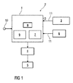
図1には、流体式変速機2の油圧を制御する制御装置1のブロック回路図が概略的に示されている。
FIG. 1 schematically shows a block circuit diagram of a
流体式変速機2は、車両駆動部の自動変速機として構成されており、とりわけ、変速機制御ユニット3、機械的調整弁4、クラッチ5、並びに流体式変速機2の油圧媒体の温度を検出するための任意の温度センサ6を有している。
The fluid transmission 2 is configured as an automatic transmission of a vehicle drive unit, and in particular detects the temperature of the
制御装置1は、電磁弁9、該電磁弁9の圧力出力側における油圧の圧力実際値を検出する圧力センサ7、電子制御ユニット8、および図1には示されていない、前記圧力センサ7のセンサ制御と圧力信号処理のための電子センサ回路、並びに同様に図1には示されていない、前記電磁弁9の駆動制御のためのパワースイッチとを備えている。
The
この制御装置1は、圧力センサ7、電子センサ回路、電子制御ユニット8、パワースイッチおよび電磁弁9が統合されているコンパクトな電磁ユニットとして構成されている。この制御装置1は、図1には示されていない電気的エネルギー供給部のためと、変速機制御ユニット3および温度センサ6との信号通信のための電気的接続部を有し、さらに流体式変速機2のポンプ10と制御弁4に対する油圧接続部を有している。
The
電子センサ回路、電子制御ユニット8およびパワースイッチは、図1には示されていない共通の回路基板上に配置されている。電子制御ユニット8は、それぞれ1つの直接的な電気的接続部によって、圧力センサ7と、パワースイッチに接続されている。
The electronic sensor circuit, the
制御装置1には、システムバス11を介して、変速機制御ユニット3の基準圧力信号12が供給され、さらに、温度センサ6によって測定された測定信号が必要に応じて供給される。
The
電子制御ユニット8は、以下で図2に基づいてより詳細に説明するように、流体式変速機2の油圧を制御するための制御信号を、圧力センサ7を用いて検出された圧力実際値と、変速機制御ユニット3から出力された基準圧力信号とに依存して生成し、また必要に応じて温度センサの測定信号にも依存して生成する。
As will be described in more detail below with reference to FIG. 2, the
電子制御ユニット8によって生成された制御信号は、パワースイッチに供給され、このパワースイッチは当該制御信号に応じて電磁弁9を制御する。好ましくは、この制御信号は、パワースイッチを用いて電磁弁9を開閉するためのパルス幅変調された信号である。
The control signal generated by the
電磁弁9によって生成された油圧は、調整弁4の駆動制御のために用いられ、この調整弁4を用いてクラッチ5も制御される。
The hydraulic pressure generated by the
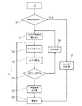
図2は、図1に示した制御装置1を用いて油圧を制御する方法のフローチャートを示す。
FIG. 2 shows a flowchart of a method for controlling the hydraulic pressure using the
この方法は、流体式変速機2の油圧を、圧力最大偏差ΔPmaxの形態で設定される精度要求を備えた圧力設定値に制御するために用いられている。圧力目標値は、基準圧力信号12を介して当該制御装置1に供給される。
This method is used to control the hydraulic pressure of the fluid transmission 2 to a pressure set value with an accuracy requirement set in the form of a pressure maximum deviation ΔPmax. The pressure target value is supplied to the
第1の方法ステップのS1では、基準圧力信号12が、制御装置1に供給された最初の基準圧力信号12であるのか否かが検査される。該当する場合(イエスの場合)には、第2の方法ステップS2において、電子制御ユニット8によって、調整信号(オープンループ信号)が、第1の制御信号として、前記基準圧力信号12に含まれる圧力目標値に依存して生成される。
In
前記方法ステップS1において検査された基準圧力信号12が制御装置1に最初に供給された基準圧力信号12でない場合には、第3の方法ステップS3において、目下の圧力目標値が読み取られる。引き続き電子制御ユニット8によって制御ループLが実施される。この制御ループLは、方法ステップS4乃至S8を含み、それらは以下で説明する。
If the
第4の方法ステップS4では、圧力センサ7を用いて検出された油圧の圧力実際値が読み出される。その後、第5の方法ステップS5において、圧力目標値と圧力実際値との間の圧力差分ΔΡが求められる。第6の方法ステップS6では、制御差分|ΔΡ|が圧力差分ΔΡの絶対値として形成され、所定の圧力最大偏差ΔPmaxと比較される。制御差分|ΔΡ|が、圧力最大偏差ΔPmaxを上回った場合には、第7の方法ステップS7において、第2の制御信号が制御偏差|ΔΡ|の低減のために生成される。第8のステップS8(これは第2の方法ステップS2の後にも実施される)では、電磁弁9がパワースイッチに供給されるそれぞれの現下の制御信号によって駆動制御され、その際にはこのパワースイッチが、当該制御信号に依存した油圧の生成のために電磁弁9を駆動制御する。
In the fourth method step S4, the actual pressure value of the hydraulic pressure detected by using the pressure sensor 7 is read. Thereafter, in a fifth method step S5, a pressure difference ΔΡ between the pressure target value and the actual pressure value is obtained. In a sixth method step S6, the control difference | ΔΡ | is formed as the absolute value of the pressure difference ΔΡ and compared with a predetermined maximum pressure deviation ΔPmax. If the control difference | ΔΡ | exceeds the maximum pressure deviation ΔPmax, in a seventh method step S7, a second control signal is generated for reducing the control deviation | ΔΡ |. In an eighth step S8 (which is also carried out after the second method step S2), the
制御ループLは、制御差分|ΔΡ|が、圧力最大偏差ΔPmaxを上回った場合には、繰り返され、そうでない場合には第6のステップS6の後に中断される。 The control loop L is repeated when the control difference | ΔΡ | exceeds the maximum pressure deviation ΔPmax, and is interrupted after the sixth step S6.
第6の方法ステップS6における制御ループLの中断後、第9の方法ステップS9では、時間測定が開始される。その後、所定の休止期間の経過後若しくは変更された圧力目標値が基準圧力信号12によって制御装置1に供給される場合には、再び第3の方法ステップS3が実施される。
After interruption of the control loop L in the sixth method step S6, time measurement is started in a ninth method step S9. Thereafter, after the elapse of a predetermined pause period or when the changed pressure target value is supplied to the
上述した制御アルゴリズムは、例えば、比例積分微分(PID)制御、自由度二制御、またはファジー制御で実施されてもよい。さらに前記制御信号は、付加的に温度センサ6によって検出された流体式変速機2の作動油温度に依存して更新されてもよい。
The control algorithm described above may be implemented by, for example, proportional integral derivative (PID) control, two-degree-of-freedom control, or fuzzy control. Furthermore, the control signal may additionally be updated depending on the hydraulic oil temperature of the fluid transmission 2 detected by the
1 制御装置
2 流体式変速機
3 変速機制御ユニット
4 操作バルブ
5 クラッチ
6 温度センサ
7 圧力センサ
8 電子制御ユニット
9 電磁弁
10 ポンプ
11 バスシステム
12 基準圧力信号
L 制御ループ
ΔP 圧力差分
|ΔP| 制御差分
ΔPmax 最大圧力偏差
S1乃至S9 方法ステップ
DESCRIPTION OF
Claims (10)
前記制御装置(1)は、
前記油圧の圧力実際値を検出する圧力センサ(7)と、
前記圧力センサ(7)のセンサ制御と圧力信号処理のための圧力センサ(7)用電子センサ回路と、
前記圧力センサ(7)によって検出された圧力実際値と、基準圧力信号(12)とに依存して制御信号を生成する電子制御ユニット(8)であって、前記基準圧力信号(12)は前記電子制御ユニット(8)に供給される、電子制御ユニット(8)と、
前記制御信号によって制御されるパワースイッチと、
前記パワースイッチによって駆動制御され、油圧を生成するための電磁弁(9)とを含み、
前記圧力センサ(7)、前記電子センサ回路、前記電子制御ユニット(8)、前記パワースイッチ、および前記電磁弁(9)は、電気的エネルギー供給および信号通信のための電気的接続部と、流体式変速機(2)に対する油圧接続部とを備えた小型の電磁ユニットとして構成され、
前記電子制御ユニット(8)は、それぞれ1つの直接的な電気的接続部によって前記圧力センサ(7)と前記パワースイッチとに接続されている、制御装置(1)を用いて流体式変速機(2)の油圧を制御する方法であって、
−最大圧力偏差(ΔPmax)を予め定め、
−前記制御装置(1)に、基準圧力信号(12)によって圧力目標値を供給し、
−電子制御ユニット(8)によって、前記圧力目標値に依存して生成された第1の操作信号を、パワースイッチに供給し、
―前記パワースイッチによって、油圧を生成する電磁弁(9)を、第1の制御信号に依存して駆動制御し、
−下記の制御ループ(L)が実施され、すなわち、
前記圧力センサ(7)によって、前記油圧の圧力実際値が検出されて、かつ、前記電子制御ユニット(8)に供給され、
前記電子制御ユニット(8)によって圧力目標値と圧力実際値との間の制御差分(|ΔP|)が求められ、所定の最大圧力偏差(ΔPmax)と比較され、
前記制御差分(|ΔP|)が前記最大圧力偏差(ΔPmax)を上回っている場合には、前記電子制御ユニット(8)は、前記制御差分(|ΔP|)を低減する第2の制御信号を生成し、かつ、前記第2の制御信号を前記パワースイッチに供給し、さらに前記パワースイッチは、前記第2の制御信号に依存した油圧を生成するために前記電磁弁(9)を駆動制御する、前記制御ループ(L)が実施され、
−前記制御ループ(L)は、前記制御差分(|ΔP|)が前記最大圧力偏差(ΔPmax)を上回る場合には繰り返され、それ以外の場合には中断され、
休止期間が前もって設けられ、前記制御ループ(L)の各中断毎の後で、時間測定が開始され、
前記制御ループ(L)の中断後に経過した持続時間が前記休止期間に達した場合、前記制御ループ(L)は新たに実施される、
ことを特徴とする方法。 A method for controlling the hydraulic pressure of a fluid transmission (2) using a control device (1) for controlling the hydraulic pressure of a fluid transmission (2).
The control device (1)
A pressure sensor (7) for detecting the actual pressure value of the hydraulic pressure;
An electronic sensor circuit for the pressure sensor (7) for sensor control and pressure signal processing of the pressure sensor (7);
An electronic control unit (8) that generates a control signal depending on an actual pressure value detected by the pressure sensor (7) and a reference pressure signal (12), wherein the reference pressure signal (12) An electronic control unit (8) supplied to the electronic control unit (8);
A power switch controlled by the control signal;
A solenoid valve (9) that is driven and controlled by the power switch to generate hydraulic pressure,
The pressure sensor (7), the electronic sensor circuit, the electronic control unit (8), the power switch, and the solenoid valve (9) include an electrical connection for electrical energy supply and signal communication, a fluid Configured as a small electromagnetic unit with a hydraulic connection to the transmission (2),
The electronic control unit (8) is connected to the pressure sensor (7) and the power switch by a single direct electrical connection, respectively , using a control device (1) to make a fluid transmission ( 2) a method of controlling the hydraulic pressure,
-Predetermine the maximum pressure deviation (ΔPmax);
Supplying the control device (1) with a pressure target value by means of a reference pressure signal (12);
A first operating signal generated by the electronic control unit (8) depending on the pressure target value is supplied to the power switch;
The drive control of the solenoid valve (9) for generating hydraulic pressure by the power switch depending on the first control signal;
The following control loop (L) is implemented:
An actual pressure value of the hydraulic pressure is detected by the pressure sensor (7) and supplied to the electronic control unit (8).
A control difference (| ΔP |) between the pressure target value and the actual pressure value is determined by the electronic control unit (8) and compared with a predetermined maximum pressure deviation (ΔPmax),
When the control difference (| ΔP |) exceeds the maximum pressure deviation (ΔPmax), the electronic control unit (8) outputs a second control signal for reducing the control difference (| ΔP |). Generating and supplying the second control signal to the power switch, and the power switch drives and controls the electromagnetic valve (9) to generate a hydraulic pressure dependent on the second control signal. The control loop (L) is implemented;
The control loop (L) is repeated if the control difference (| ΔP |) exceeds the maximum pressure deviation (ΔPmax), otherwise interrupted ;
A pause period is provided in advance, and after each interruption of the control loop (L), a time measurement is started ,
If the duration that has elapsed after the interruption of the control loop (L) reaches the pause period, the control loop (L) is newly implemented ,
A method characterized by that.
前記基準圧力信号(12)によって、変更された圧力目標値が前記制御装置(1)に供給された場合は、前記制御ループ(L)は新たに実施される、請求項1記載の方法。 A pause period is provided in advance, and after each interruption of the control loop (L), a time measurement is started,
By the standards pressure signal (12), modified if the pressure target value is supplied to the control device (1), wherein the control loop (L) is newly implemented method of claim 1, wherein.
Applications Claiming Priority (3)
| Application Number | Priority Date | Filing Date | Title |
|---|---|---|---|
| DE102013221453.7 | 2013-10-23 | ||
| DE201310221453 DE102013221453A1 (en) | 2013-10-23 | 2013-10-23 | Regulation of a hydraulic pressure of a flow gear |
| PCT/EP2014/072249 WO2015059032A2 (en) | 2013-10-23 | 2014-10-16 | Controlling a hydraulic pressure of a fluid transmission |
Publications (2)
| Publication Number | Publication Date |
|---|---|
| JP2016533559A JP2016533559A (en) | 2016-10-27 |
| JP6234561B2 true JP6234561B2 (en) | 2017-11-22 |
Family
ID=51790683
Family Applications (1)
| Application Number | Title | Priority Date | Filing Date |
|---|---|---|---|
| JP2016519361A Active JP6234561B2 (en) | 2013-10-23 | 2014-10-16 | Method for controlling the hydraulic pressure of a fluid transmission |
Country Status (5)
| Country | Link |
|---|---|
| US (1) | US9568095B2 (en) |
| EP (1) | EP3017346A2 (en) |
| JP (1) | JP6234561B2 (en) |
| DE (1) | DE102013221453A1 (en) |
| WO (1) | WO2015059032A2 (en) |
Families Citing this family (4)
| Publication number | Priority date | Publication date | Assignee | Title |
|---|---|---|---|---|
| EP3627274B1 (en) * | 2018-09-24 | 2020-10-28 | Siemens Aktiengesellschaft | Fluid pressure control apparatus and system |
| DE102019204724B3 (en) | 2019-04-03 | 2020-10-01 | Audi Ag | Method for operating a hydraulic valve of a hydraulic device of a motor vehicle transmission device and motor vehicle transmission device |
| EP3882737B1 (en) * | 2020-03-20 | 2022-04-27 | Siemens Aktiengesellschaft | Fluid pressure control apparatus |
| CN115388329B (en) * | 2022-08-25 | 2024-03-12 | 青岛明华电子仪器有限公司 | Gas cylinder gas supply device and pressure control method thereof |
Family Cites Families (15)
| Publication number | Priority date | Publication date | Assignee | Title |
|---|---|---|---|---|
| GB9608256D0 (en) * | 1996-04-20 | 1996-06-26 | Ap Kongsberg Holdings Ltd | Actuation systems |
| DE50109507D1 (en) * | 2000-09-18 | 2006-05-24 | Siemens Ag | METHOD FOR CONTROLLING AN AUTOMATIC MOTOR VEHICLE COUPLING |
| DE10145588A1 (en) * | 2001-09-15 | 2003-04-24 | Deere & Co | Method and device for controlling a clutch |
| US6779541B2 (en) * | 2001-10-12 | 2004-08-24 | Smc Kabushiki Kaisha | Fluid pressure regulator |
| DE102005004080A1 (en) | 2005-01-28 | 2006-08-03 | Robert Bosch Gmbh | Electromagnetic pressure control valve arrangement for hydraulic clutch, has electronic part with pressure sensor measuring hydraulic pressure applied to load connection, where sensor is placed on magnetic part end, which faces valve part |
| JP4678336B2 (en) * | 2006-05-31 | 2011-04-27 | 日産自動車株式会社 | Diagnostic apparatus and diagnostic method for air-fuel ratio sensor |
| US20080082242A1 (en) * | 2006-10-03 | 2008-04-03 | Dell Eva Mark L | Mode selection and switching logic in a closed-loop pulse width modulation valve-based transmission control system |
| US8192318B2 (en) * | 2007-03-26 | 2012-06-05 | Delphi Technologies, Inc. | Automatic transmission with closed loop pressure electro-hydraulic control module |
| US7850572B2 (en) * | 2007-07-31 | 2010-12-14 | Delphi Technologies, Inc. | Hydraulic over/undershoot protection for transmission clutch control |
| US8989971B2 (en) * | 2008-05-27 | 2015-03-24 | Eaton Corporation | Method and apparatus for detecting and compensating for pressure transducer errors |
| US8408516B2 (en) | 2009-04-27 | 2013-04-02 | GM Global Technology Operations LLC | Fluid pressure control device with integrated pressure sensor |
| JP5215937B2 (en) * | 2009-05-19 | 2013-06-19 | 富士重工業株式会社 | Hydraulic control device |
| JP4990333B2 (en) * | 2009-09-03 | 2012-08-01 | 株式会社小松製作所 | Work vehicle |
| US20150047720A1 (en) | 2012-03-27 | 2015-02-19 | Brt Group Pty Ltd | Solenoid device with sensor |
| JP5496259B2 (en) * | 2012-06-12 | 2014-05-21 | 三菱電機株式会社 | Transmission control device and output characteristic adjustment method of transmission control device |
-
2013
- 2013-10-23 DE DE201310221453 patent/DE102013221453A1/en active Pending
-
2014
- 2014-10-16 US US15/031,789 patent/US9568095B2/en active Active
- 2014-10-16 WO PCT/EP2014/072249 patent/WO2015059032A2/en active Application Filing
- 2014-10-16 JP JP2016519361A patent/JP6234561B2/en active Active
- 2014-10-16 EP EP14787141.2A patent/EP3017346A2/en not_active Ceased
Also Published As
| Publication number | Publication date |
|---|---|
| WO2015059032A2 (en) | 2015-04-30 |
| WO2015059032A3 (en) | 2015-06-18 |
| US9568095B2 (en) | 2017-02-14 |
| EP3017346A2 (en) | 2016-05-11 |
| US20160245398A1 (en) | 2016-08-25 |
| JP2016533559A (en) | 2016-10-27 |
| DE102013221453A1 (en) | 2015-04-23 |
Similar Documents
| Publication | Publication Date | Title |
|---|---|---|
| JP6234561B2 (en) | Method for controlling the hydraulic pressure of a fluid transmission | |
| CN104033643A (en) | Current control device for solenoid, and method for controlling current of solenoid | |
| KR101116474B1 (en) | Method of calibrating a solenoid operated pressure control valve and method of controlling same | |
| KR101912802B1 (en) | Coolant pump with integrated closed-loop control | |
| CN110753979B (en) | Method and device for controlling a component that can be moved by means of a coil, and magnetic valve | |
| JP4971421B2 (en) | Control device provided with regulator for adjusting coil current of control solenoid valve | |
| US20170370274A1 (en) | Coolant pump with integrated closed-loop control | |
| US8165762B2 (en) | Method of operating a transmission system valve configuration | |
| JP2008215611A (en) | Mode selection and switching logic in closed-loop pulse width modulation valve-based transmission control system | |
| CN107850232B (en) | Control device | |
| JP2012091577A (en) | Control device of linear solenoid valve | |
| CN102384119B (en) | Method, device and system for speed regulation control of electro-hydraulic proportional valve and engineering machinery equipment | |
| US7260462B2 (en) | Method for controlling an electromagnetic valve, in particular for an automatic transmission of a motor vehicle | |
| JP2005038390A (en) | Status detecting device for load element to accept load of working fluid and status detecting device for fluid pressure control circuit | |
| CN108292554B (en) | Current monitoring on a consumer | |
| JP6813507B2 (en) | Pressure controller | |
| JP2010276077A (en) | Opening control device for solenoid driving valve | |
| KR20090047753A (en) | Mode selection and switching logic in a closed-loop pulse width modulation valve-based transmission control system | |
| US20230224197A1 (en) | Circuit and method for determining a dither amplitude | |
| CN107209510B (en) | Method for identifying a characteristic curve | |
| JP6344070B2 (en) | Solenoid control device | |
| CN108474422B (en) | Electrohydraulic transmission clutch mechanism for motor vehicles | |
| JP2000337542A (en) | Proportional solenoid valve | |
| JP2018080736A (en) | Clutch control device | |
| JP2018040430A (en) | Clutch control device |
Legal Events
| Date | Code | Title | Description |
|---|---|---|---|
| A131 | Notification of reasons for refusal |
Free format text: JAPANESE INTERMEDIATE CODE: A131 Effective date: 20170403 |
|
| A521 | Request for written amendment filed |
Free format text: JAPANESE INTERMEDIATE CODE: A523 Effective date: 20170608 |
|
| A131 | Notification of reasons for refusal |
Free format text: JAPANESE INTERMEDIATE CODE: A131 Effective date: 20170710 |
|
| TRDD | Decision of grant or rejection written | ||
| A01 | Written decision to grant a patent or to grant a registration (utility model) |
Free format text: JAPANESE INTERMEDIATE CODE: A01 Effective date: 20170925 |
|
| A61 | First payment of annual fees (during grant procedure) |
Free format text: JAPANESE INTERMEDIATE CODE: A61 Effective date: 20171024 |
|
| R150 | Certificate of patent or registration of utility model |
Ref document number: 6234561 Country of ref document: JP Free format text: JAPANESE INTERMEDIATE CODE: R150 |
|
| R250 | Receipt of annual fees |
Free format text: JAPANESE INTERMEDIATE CODE: R250 |
|
| R250 | Receipt of annual fees |
Free format text: JAPANESE INTERMEDIATE CODE: R250 |
|
| R250 | Receipt of annual fees |
Free format text: JAPANESE INTERMEDIATE CODE: R250 |
|
| R250 | Receipt of annual fees |
Free format text: JAPANESE INTERMEDIATE CODE: R250 |
|
| S111 | Request for change of ownership or part of ownership |
Free format text: JAPANESE INTERMEDIATE CODE: R313113 |
|
| R350 | Written notification of registration of transfer |
Free format text: JAPANESE INTERMEDIATE CODE: R350 |