JP6233965B2 - Magnetic resonance imaging apparatus and RF shimming method - Google Patents
Magnetic resonance imaging apparatus and RF shimming method Download PDFInfo
- Publication number
- JP6233965B2 JP6233965B2 JP2013263246A JP2013263246A JP6233965B2 JP 6233965 B2 JP6233965 B2 JP 6233965B2 JP 2013263246 A JP2013263246 A JP 2013263246A JP 2013263246 A JP2013263246 A JP 2013263246A JP 6233965 B2 JP6233965 B2 JP 6233965B2
- Authority
- JP
- Japan
- Prior art keywords
- image
- coil
- mask
- map
- magnetic field
- Prior art date
- Legal status (The legal status is an assumption and is not a legal conclusion. Google has not performed a legal analysis and makes no representation as to the accuracy of the status listed.)
- Active
Links
- 238000002595 magnetic resonance imaging Methods 0.000 title claims description 27
- 238000000034 method Methods 0.000 title claims description 15
- 238000005259 measurement Methods 0.000 claims description 27
- 238000003384 imaging method Methods 0.000 claims description 14
- 238000005481 NMR spectroscopy Methods 0.000 claims description 10
- 230000001678 irradiating effect Effects 0.000 claims 2
- 230000002194 synthesizing effect Effects 0.000 claims 2
- 238000004364 calculation method Methods 0.000 description 22
- 230000005540 biological transmission Effects 0.000 description 20
- 230000036278 prepulse Effects 0.000 description 16
- 238000009826 distribution Methods 0.000 description 15
- 230000003068 static effect Effects 0.000 description 10
- 238000001208 nuclear magnetic resonance pulse sequence Methods 0.000 description 9
- 238000010586 diagram Methods 0.000 description 8
- 238000003860 storage Methods 0.000 description 3
- 238000005516 engineering process Methods 0.000 description 2
- 230000000873 masking effect Effects 0.000 description 2
- 210000001015 abdomen Anatomy 0.000 description 1
- 230000003187 abdominal effect Effects 0.000 description 1
- 238000001514 detection method Methods 0.000 description 1
- 230000005284 excitation Effects 0.000 description 1
- 239000004615 ingredient Substances 0.000 description 1
- 230000005415 magnetization Effects 0.000 description 1
- 238000004519 manufacturing process Methods 0.000 description 1
- 239000011159 matrix material Substances 0.000 description 1
- 230000003287 optical effect Effects 0.000 description 1
- 238000002360 preparation method Methods 0.000 description 1
Images


Landscapes
- Magnetic Resonance Imaging Apparatus (AREA)
Description
本発明は、磁気共鳴イメージング(以下、MRIという。)装置に係り、特に、被検体を撮像して得られた画像を好適にマスクして、安定的にRFシミングに必要なB1マップを取得することが可能なMRI装置に関する。 The present invention relates to a magnetic resonance imaging (hereinafter, referred to as MRI) apparatus, and in particular, suitably masks an image obtained by imaging a subject and stably acquires a B1 map necessary for RF shimming. It relates to an MRI apparatus capable of
MRI装置は、被検体、特に人体の組織を構成する原子核スピンが発生するNMR信号を計測し、その頭部、腹部、四肢等の形態や機能を2次元的に或いは3次元的に画像化する装置である。撮影においては、NMR信号には、傾斜磁場によって異なる位相エンコードが付与されるとともに周波数エンコードされて、時系列データとして計測される。傾斜磁場によって異なる位相エンコードが付与されるとともに周波数エンコードされて、時系列データとして計測される。計測されたNMR信号は、2次元又は3次元フーリエ変換することにより、画像に再構成される。 The MRI device measures NMR signals generated by the spins of the subject, especially the tissues of the human body, and visualizes the form and function of the head, abdomen, limbs, etc. in two or three dimensions Device. In imaging, the NMR signal is given different phase encoding depending on the gradient magnetic field, frequency-encoded, and measured as time series data. Different phase encodings are applied depending on the gradient magnetic field, and frequency encoding is performed, and measurement is performed as time-series data. The measured NMR signal is reconstructed into an image by two-dimensional or three-dimensional Fourier transform.
近年、3T以上の高磁場MRI装置が普及している。高磁場MRI装置では、MRI装置に比べて、高い磁場中に被検体を配置するため、S/Nの高い画像が得られるが、腹部撮像等で画像にムラが発生する問題がある。このムラの原因の一つとしては、MRI装置に用いられるRF照射磁場の磁場分布(B1マップ)が空間的に一様でないこと、即ち、送信RF照射磁場の磁場分布が空間的に不均一な成分を持っていることが考えられる。高磁場MRI装置では、使用されるRFパルスの周波数が高いため、その分被検体に照射されるRF照射磁場が吸収されやすく、RF照射磁場の局所的な分布の差が、生成されたMRI画像にムラとなって現れる。 In recent years, high magnetic field MRI apparatuses of 3T or more have become widespread. In the high magnetic field MRI apparatus, since the subject is placed in a high magnetic field as compared with the MRI apparatus, an image having a high S / N can be obtained. However, there is a problem that unevenness occurs in the image due to abdominal imaging or the like. One of the causes of this unevenness is that the magnetic field distribution (B1 map) of the RF irradiation magnetic field used in the MRI apparatus is not spatially uniform, that is, the magnetic field distribution of the transmission RF irradiation magnetic field is spatially non-uniform. It is thought that it has an ingredient. In the high magnetic field MRI system, the frequency of the RF pulse used is high, so the RF irradiation magnetic field irradiated to the subject is easily absorbed, and the difference in the local distribution of the RF irradiation magnetic field is generated. Appears as uneven.
このようなRFパルスの磁場分布の不均一に起因するMRI画像のムラを解決する技術として、RFシミングがある。RFシミングとは、複数チャンネル備えられた送信用RFコイルを用い、各チャンネルに与えるRFパルスの強度と位相を独立に制御することで、被検体に均一にRFパルスが照射されるようにする技術である。ただし、RFシミングを行うためには実際に被検体を均一磁場空間に配置した状態で各送信用RFコイルにより照射される照射磁場分布をB1マップとして測定する必要がある。 There is RF shimming as a technique for solving the unevenness of the MRI image due to such non-uniform magnetic field distribution of the RF pulse. RF shimming is a technology that uses an RF coil for transmission with multiple channels and controls the intensity and phase of the RF pulse applied to each channel independently, so that the subject is evenly irradiated with RF pulses. It is. However, in order to perform RF shimming, it is necessary to measure the irradiation magnetic field distribution irradiated by each transmission RF coil as a B1 map in a state where the subject is actually arranged in the uniform magnetic field space.
B1マップの測定に関する従来技術として、特許文献1記載の技術がある。
As prior art relating B1 map measurements, there is a technology described in Patent Document 1.
しかしながら、特許文献1では、B1マップの取得に必要なマスクの作成について、検討されていない。特に、B1マップの測定のために、被検体が配置された領域(信号領域)と背景の被検体が配置されていない領域(マスク領域)が適切にマスクの作成によって区別されない場合には、B1マップが正確に求められず、得られるMRI画像にもアーチファクトが生じるおそれがあった。 However, Patent Document 1 does not discuss creation of a mask necessary for obtaining a B1 map. In particular, for the measurement of the B1 map, if the area where the subject is placed (signal area) and the area where the background subject is not placed (mask area) are not properly distinguished by creating a mask, B1 The map could not be obtained accurately, and there was a risk of artifacts in the obtained MRI image.
本発明の目的は、被検体を撮像して得られた画像を好適にマスクして、安定的にRFシミングに必要なB1マップを取得することが可能なMRI装置を提供することにある。 An object of the present invention is to provide an MRI apparatus capable of suitably masking an image obtained by imaging a subject and stably acquiring a B1 map necessary for RF shimming.
上記の課題を解決するために、複数のRFコイルを有して成り被検体に核磁気共鳴を起こさせるための高周波磁場を照射するRF照射コイルを備えた磁気共鳴イメージング装置は、RF照射コイルを介して被検体から複数のエコー信号を計測し、複数のエコー信号を画像再構成してRFコイル毎の画像を生成し、RFコイル毎の画像を合成してマスク作成用画像を生成し、マスク作成用画像内の寝台より下の領域の画素値に基づいてノイズ統計量を計算し、ノイズ統計量に基づいて閾値を決定し、マスク作成用画像と閾値を用いてマスク画像を生成し、RFコイル毎の画像とマスク画像を用いてRF照射コイルのB1マップを算出し、B1マップに基いてRFコイル毎に印加されるRFパルスの振幅と位相を算出し、RFコイル毎に算出されたRFパルスの振幅と位相を用いて複数のエコー信号の計測を行う。
In order to solve the above problems, a magnetic resonance imaging apparatus having an RF irradiation coil that includes a plurality of RF coils and irradiates a subject with a high-frequency magnetic field for causing nuclear magnetic resonance is provided. Multiple echo signals are measured from the subject, and the images of each RF coil are generated by reconstructing the images of the multiple echo signals, and the image for creating the mask is generated by combining the images for each RF coil. Calculate the noise statistic based on the pixel value of the area below the bed in the image for creation, determine the threshold based on the noise statistic, generate a mask image using the image for mask creation and the threshold, Calculate the B1 map of the RF irradiation coil using the image and mask image for each coil, calculate the amplitude and phase of the RF pulse applied to each RF coil based on the B1 map, and calculate the RF calculated for each RF coil Duplicate using the amplitude and phase of the pulse. Carry out the measurement of the echo signal.
本発明によれば、被検体を撮像して得られた画像を好適にマスクして、安定的にRFシミングに必要なB1マップを取得することが可能なMRI装置を提供することができる。 According to the present invention, it is possible to provide an MRI apparatus capable of suitably masking an image obtained by imaging a subject and stably acquiring a B1 map necessary for RF shimming.
以下、本発明の実施の形態を説明する。まず本発明が適用されるMRI装置の全体構成について、図面を参照して説明する。 Embodiments of the present invention will be described below. First, an overall configuration of an MRI apparatus to which the present invention is applied will be described with reference to the drawings.
図1は、本発明が適用されるMRI装置の一実施形態を示すブロック図である。このMRI装置は、静磁場発生系2と、傾斜磁場発生系3と、送信系5と、受信系6と、信号処理系7と、シーケンサ4と、中央処理装置(演算処理部、CPU)8とを備えて構成される。
FIG. 1 is a block diagram showing an embodiment of an MRI apparatus to which the present invention is applied. This MRI apparatus includes a static magnetic field generation system 2, a gradient magnetic
静磁場発生系2は、被検体1が置かれる空間に均一な静磁場を発生するものであり、永久磁石方式、常電導方式あるいは超電導方式の静磁場発生源(不図示)からなる。静磁場発生源は、垂直磁場方式であれば、被検体1の体軸と直交する方向に、水平磁場方式であれば、体軸方向に、均一な静磁場を発生させるように、配置されている。 The static magnetic field generation system 2 generates a uniform static magnetic field in the space in which the subject 1 is placed, and includes a permanent magnet type, normal conduction type or superconductivity type static magnetic field generation source (not shown). The static magnetic field generation source is arranged so as to generate a uniform static magnetic field in the direction perpendicular to the body axis of the subject 1 in the vertical magnetic field method, and in the body axis direction in the horizontal magnetic field method. Yes.
傾斜磁場発生系3は、MRI装置の座標系(静止座標系)であるX、Y、Zの直交3軸方向に傾斜磁場を印加する傾斜磁場コイル9と、それぞれの傾斜磁場コイル9を駆動する傾斜磁場電源10とから成る。後述のシ-ケンサ4からの命令に従ってそれぞれのコイルの傾斜磁場電源10を駆動することにより、X、Y、Zの3軸方向に所望の傾斜磁場Gx,Gy,Gzを印加することができる。傾斜磁場の印加の仕方によって、被検体の撮像スライスを選択的に励起し、また励起領域から発生するエコー信号(NMR信号)に位置情報を加えることができる。
The gradient magnetic
シーケンサ4は、RFパルスと傾斜磁場パルスをある所定のパルスシーケンスで繰り返し印加する制御手段で、CPU8の制御で動作し、被検体1の断層画像のデータ収集に必要な種々の命令を送信系5、傾斜磁場発生系3、および受信系6に送る。
The
送信系5は、被検体1の生体組織を構成する原子の原子核スピンに核磁気共鳴を起こさせるために、被検体1にRFパルスを照射するもので、高周波発振器11と変調器12と高周波増幅器13と送信側の高周波コイル(送信コイル)14aとから成る。送信コイル14aは、本実施形態では、複数の給電点を有し、供給される高周波の強度と位相を調整できるように構成されている。高周波発振器11、変調器12及び高周波増幅器13は、各チャンネルに対応して複数備えられている。図では、2つの給電点がある場合を示しているが、給電点の数は2に限定されない。
The transmission system 5 irradiates the subject 1 with RF pulses in order to cause nuclear magnetic resonance to occur in the nuclear spins of the atoms constituting the living tissue of the subject 1, and includes a high frequency oscillator 11, a
高周波発振器11から出力されたRFパルスをシーケンサ4からの指令によるタイミングで変調器12により振幅変調し、この振幅変調されたRFパルスを高周波増幅器13で増幅した後に被検体1に近接して配置された高周波コイル14aに供給することにより、RFパルスが被検体1に照射される。シーケンサ4からのタイミングと変調器12による変調は、後述するB1分布の計測結果を反映して制御される。
The RF pulse output from the high-frequency oscillator 11 is amplitude-modulated by the
受信系6は、被検体1の生体組織を構成する原子核スピンの核磁気共鳴により放出されるエコー信号を検出するもので、受信側の高周波コイル(受信コイル)14bと信号増幅器15と直交位相検波器16と、A/D変換器17とから成る。送信コイル14aから照射された電磁波によって誘起された被検体1の応答のNMR信号が被検体1に近接して配置された受信コイル14bで検出され、信号増幅器15で増幅された後、シーケンサ4からの指令によるタイミングで直交位相検波器16により直交する二系統の信号に分割され、それぞれがA/D変換器17でディジタル量に変換されて、信号処理系7に送られる。
The receiving system 6 detects an echo signal emitted by nuclear magnetic resonance of nuclear spins constituting the biological tissue of the subject 1, and receives a high-frequency coil (receiving coil) 14b on the receiving side, a
なお図1では、送信用の高周波コイルと受信用の高周波コイルが、別個に設けられている構成を示しているが、一つの高周波コイル(マルチプルコイルを含む)が送信用及び受信用を兼ねる構成とすることも可能である。 Although FIG. 1 shows a configuration in which a high-frequency coil for transmission and a high-frequency coil for reception are separately provided, a configuration in which one high-frequency coil (including multiple coils) serves both for transmission and reception It is also possible.
信号処理系7は、CPU8と、各種データ処理と処理結果の表示及び保存等を行うもので、光ディスク19、磁気ディスク18等の外部記憶装置と、CRT等からなるディスプレイ20とを有する。受信系6からのデータがCPU8に入力されると、CPU8が信号処理、画像再構成等の処理を実行し、その結果である被検体1の断層画像をディスプレイ20に表示すると共に、外部記憶装置の磁気ディスク18等に記録する。
The signal processing system 7 performs
CPU8は、信号処理系7の演算部としての機能のほかに、装置の各要素を制御する制御部としての機能を有し、シーケンサ4を介して、種々のパルスシーケンスを実行させる。パルスシーケンスは、予めプログラムとして組み込まれている。本実施形態では、送信コイルによる照射磁場分布(B1分布)を計測するためのB1分布計測シーケンスを備えている。また信号処理系7は、このB1分布計測シーケンスの計測結果を用いて、B1分布の計算や送信コイル14aに与えられる高周波パルスの位相や振幅の計算を行い、この計算結果に基づき、送信コイル14aに与えられる高周波パルスの位相や振幅を制御する。
The
操作部25は、MRI装置の各種制御情報や上記信号処理系7で行う処理の制御情報を入力するもので、トラックボール又はマウス23、及び、キーボード24から成る。この操作部25はディスプレイ20に近接して配置され、操作者がディスプレイ20を見ながら操作部25を通してインタラクティブにMRI装置の各種処理を制御する。
The
なお、図1において、送信側の高周波コイル14aと傾斜磁場コイル9は、被検体1が挿入される静磁場発生系2の静磁場空間内に、垂直磁場方式であれば被検体1に対向して、水平磁場方式であれば被検体1を取り囲むようにして設置されている。また、受信側の高周波コイル14bは、被検体1に対向して、或いは取り囲むように設置されている。
In FIG. 1, the high-
次に、本発明の実施例1に係るMRI装置のブロック図を説明する。図2は、図1におけるCPUが実行する各機能を示した図であり、位置決め部26と、B1マップ計測シーケンス実行部27と、画像再構成部28と、マスク作成部29と、B1マップ算出部30と、RFパルスの振幅と位相計算・設定部31と、撮像制御部32とより成る。
Next, a block diagram of the MRI apparatus according to Embodiment 1 of the present invention will be described. FIG. 2 is a diagram illustrating each function executed by the CPU in FIG. 1, and includes a
位置決め部26は、スカウト画像等を撮像することによって、被検体1を撮像空間の中心に配置するための制御をするものである。
The
B1マップ計測シーケンス実行部27は、位置決め部26に接続され、後述するようにB1マップを計測するためのシーケンスを実行し、チャンネル毎のエコー信号を得るためのものである。
The B1 map measurement
画像再構成部28は、B1マップ計測シーケンス実行部27に接続され、B1マップ計測シーケンス実行部27により得られたチャンネル毎のエコー信号を画像再構成して、チャンネル毎の画像を生成するためのものである。
The
マスク作成部29は、画像再構成部28に接続され、B1マップ作成を、被検体1が配置された信号領域からのみとするためのマスク画像を作成するものである。
The
B1マップ算出部30は、画像再構成部28及びマスク作成部29に接続され、画像再構成部28により得られた画像とマスク作成部29により作成されたマスク画像を用い、B1マップを作成するためのものである。
The B1
RFパルスの振幅と位相計算・設定部31は、B1マップ算出部30に接続され、B1マップ算出部30で作成したB1マップを用いて各RFコイルのチャンネルに印加するRFパルスの振幅と位相を計算及び設定するためのものである。
The RF pulse amplitude and phase calculation /
撮像制御部32は、RFパルスの振幅と位相計算・設定部31に接続され、RFパルスの振幅と位相計算・設定部31で設定したRFパルスの振幅と位相で被検体1を撮像するためのものである。
The
更に、図3は、実施例1におけるマスク作成部29の内部構成を示す図である。マスク作成部29は、マスク作成用画像生成部29-1と、平均値・標準偏差計算部29-2と、閾値決定部29-3と、閾値処理部29-4とより成る。
FIG. 3 is a diagram illustrating an internal configuration of the
マスク作成用画像生成部29-1は、画像再構成部28に接続され、画像再構成部28で得られたチャンネル毎の画像を加算して、1枚のマスク作成用画像を生成するためのものである。
The mask creation image generation unit 29-1 is connected to the
平均値・標準偏差計算部29-2は、マスク作成用画像生成部29-1に接続され、マスク作成用画像生成部29-1が作成したマスク作成用画像から、寝台より下の部分の領域(図4の35の部分)の画素値の平均値、標準偏差を計算するためのものである。ただし、図4において、1は被検体、33は天板、34は画像の枠である。 The average value / standard deviation calculation unit 29-2 is connected to the mask creation image generation unit 29-1, and is an area below the bed from the mask creation image created by the mask creation image generation unit 29-1. This is for calculating the average value and standard deviation of the pixel values (35 portion in FIG. 4). In FIG. 4, 1 is a subject, 33 is a top plate, and 34 is an image frame.
閾値決定部29-3は、平均値・標準偏差計算部29-2に接続され、平均値・標準偏差計算部29-2により計算された平均値(Av)・標準偏差(Sd)より閾値(Th)を、例えばTh=Av+20×Sdとして、決定するためのものである。 The threshold value determination unit 29-3 is connected to the average value / standard deviation calculation unit 29-2, and the threshold value (Av) / standard deviation (Sd) calculated by the average value / standard deviation calculation unit 29-2 For example, Th) is determined as Th = Av + 20 × Sd.
閾値処理部29-4は、マスク作成用画像生成部29-1と閾値決定部29-3に接続され、閾値決定部29-3により決定された閾値を用い、マスク作成用画像生成部29-1により作成されたマスク作成用画像に閾値処理を施し、マスク画像を作成するためのものである。より具体的には、例えば64×64からなるマスク画像を作成する。 The threshold processing unit 29-4 is connected to the mask creating image generating unit 29-1 and the threshold determining unit 29-3, and uses the threshold determined by the threshold determining unit 29-3 to use the mask generating image generating unit 29- This is for applying a threshold process to the mask creation image created in 1 to create a mask image. More specifically, for example, a 64 × 64 mask image is created.
次に図5は、実施例1におけるB1マップ計測を行う手順を示すフローチャートを示す図である。図5に手順を示す。 Next, FIG. 5 is a flowchart illustrating a procedure for performing B1 map measurement according to the first embodiment. Figure 5 shows the procedure.
(ステップ201)
操作者は、被検体1を静磁場空間に配置して位置決め部26に備えられたプログラム等を用いスカウト画像を取得し、目的とする被検体1の撮像部位が静磁場空間のほぼ中央に位置するように被検体1を移動させて位置決めを行う。
(Step 201)
The operator arranges the subject 1 in the static magnetic field space, acquires a scout image using a program or the like provided in the
(ステップ202)
B1マップ計測シーケンス実行部27は、送信コイルのチャンネル毎に、B1マップ計測シーケンスを実行し送信コイルのチャンネル毎に、エコー信号を取得する。B1マップ計測シーケンスについては、後述する。
(Step 202)
The B1 map measurement
(ステップ203)
画像再構成部28は、ステップ202で取得された送信コイルのチャンネル毎のエコー信号を用いて画像再構成演算を行い、送信コイルのチャンネル毎の画像を生成する。
(Step 203)
The
(ステップ204)
マスク作成部29は、ステップ203 で得られた送信コイルのチャンネル毎の画像に基づいて、信号領域とノイズ領域を区別するためのマスクを生成する。具体的なマスクの生成方法は後述する。
(Step 204)
Based on the image for each channel of the transmission coil obtained in
(ステップ205)
B1マップ算出部30は、ステップ203で取得した画像と、ステップ204で生成したマスクを用いて、チャンネル毎のB1マップを算出する。
(Step 205)
The B1
(ステップ206)
RFパルスの振幅と位相計算・設定部31は、ステップ205で算出したB1マップを用いて、各チャンネルに印加する高周波パルスの振幅と位相を計算、設定する。
(Step 206)
The RF pulse amplitude and phase calculation /
(ステップ207)
撮像制御部32は、ステップ206で設定した条件で、所望の計測(撮像)を行う。
以下、ステップ202、ステップ204、ステップ205について、詳細を説明する。
(Step 207)
The
Details of
<<B1マップ計測(ステップ202)>>
B1マップ計測シーケンスは、比較的大きなフリップ角のRFパルスからなるプリパルスと、小さなフリップ角のRFパルスを用いた信号取得シーケンスとの組合せからなり、信号取得シーケンスでは、プリパルス印加後の経過時間(TI)が異なる複数の画像を得る。プリパルスと信号取得シーケンスの組み合わせの仕方によって、異なる態様が可能であり、その態様によってB1マップ算出(ステップ205)が異なる。
<< B1 map measurement (step 202) >>
The B1 map measurement sequence consists of a combination of a pre-pulse consisting of RF pulses with a relatively large flip angle and a signal acquisition sequence using RF pulses with a small flip angle. In the signal acquisition sequence, the elapsed time (TI ) To obtain multiple images. Different modes are possible depending on the combination of the prepulse and the signal acquisition sequence, and the B1 map calculation (step 205) differs depending on the mode.
本実施例は、プリパルスの印加に引き続き、少なくとも3回の信号取得シーケンスを実行し、各信号取得シーケンスで得た画像から、B1マップを算出することが特徴である。 The present embodiment is characterized in that at least three signal acquisition sequences are executed following the application of the pre-pulse, and the B1 map is calculated from the images acquired in each signal acquisition sequence.
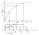
図7は、プリパルス301と信号取得シーケンス303、305、307との関係を示す図で、プリパルス301印加からの経過時間(TI)に依存した信号強度の変化を図中上側にグラフで示している。図示するグラフにおいて、横軸はプリパルス印加後の経過時間、縦軸は信号強度である。プリパルス301は、例えば非選択性のRFパルスで、フリップ角の大きい、例えば90度パルスである。このプリパルス301によって励起された原子核スピンが縦緩和している間に、少なくとも3回の信号取得シーケンス303、305、307を実行し、TIの異なる3つのk空間データ(又は画像データ)を取得する。なお、本発明では、プリパルスからの縦緩和が異なるデータを得ることが重要であり、プリパルスの影響が十分に残っている間にすべての信号取得シーケンスが完了するようにTIを設定する。これにより高精度にB1マップの計算を行うことができる。
FIG. 7 is a diagram showing the relationship between the pre-pulse 301 and the
各信号取得シーケンスは、短時間でk空間データを収集できるパルスシーケンスであれば特に限定されず、例えば、図8に示すようなグラディエントエコー(GrE)系のパルスシーケンスを採用できる。このGrE系シーケンスでは、スライス傾斜磁場パルス402とともに低フリップ角のRFパルス401を印加した後、位相エンコード傾斜磁場403を印加する。同時に読出し傾斜磁場404を印加し、極性の反転した読出し傾斜磁場の印加中にエコー信号405を計測する。最後に位相エンコード方向にリフェイズ傾斜磁場406を印加する。RFパルス401として、縦磁化に対する影響を少なくするため、好ましくは10度以下、より好ましくは5度以下の低フリップ角パルスを用いる。
Each signal acquisition sequence is not particularly limited as long as it is a pulse sequence that can collect k-space data in a short time. For example, a gradient echo (GrE) pulse sequence as shown in FIG. 8 can be adopted. In this GrE system sequence, a low-flip
このパルスシーケンスは、RFパルス401として低フリップ角パルスを用いると共に、位相エンコード方向のリフェイズ傾斜磁場406を用いているので、繰り返し時間TRを数ms(ミリ秒)程度にすることができる。RFパルス401からリフェイズ傾斜磁場406までを、位相エンコード傾斜磁場パルス403の強度を変えながら繰り返し、スライス傾斜磁場402によって選択されたスライスのデータ(k空間データ)を得る。
In this pulse sequence, a low flip angle pulse is used as the
このk空間データは、後述するB1マップの計算に用いるものであり、マトリクスサイズは64×64程度でよい。これにより、極めて短時間、具体的には200ms程度の計測時間で全k空間データを取得することができる。 This k-space data is used for calculation of the B1 map described later, and the matrix size may be about 64 × 64. As a result, the entire k-space data can be acquired in a very short time, specifically in a measurement time of about 200 ms.
k空間データから形成される画像データのコントラストは、主としてk空間データの中央のデータにより支配されるので、各信号取得シーケンスにおいてk空間データの中心のエコーを計測するタイミングをプリパルス印加からの経過時間(TI)とする。図8では、各信号取得シーケンスはk空間の中央のエコーから計測を開始する所謂セントリックオーダーのパルスシーケンスであり、信号取得シーケンスの開始時点が、それぞれTI1、TI2、TI3である。またこれら経過時間の関係は、本実施形態では、TI2=2×TI1、TI3=3×TI1の関係に設定されている。 The contrast of the image data formed from the k-space data is mainly governed by the data at the center of the k-space data, so the timing for measuring the echo at the center of the k-space data in each signal acquisition sequence is the elapsed time from the pre-pulse application. (TI). In FIG. 8, each signal acquisition sequence is a so-called centric order pulse sequence that starts measurement from an echo in the center of the k-space, and the start points of the signal acquisition sequence are TI1, TI2, and TI3, respectively. Further, in the present embodiment, the relationship between these elapsed times is set to the relationship of TI2 = 2 × TI1 and TI3 = 3 × TI1.
<<マスク生成ステップ204>>
次に、本発明の実施例1におけるマスク生成ステップ204について、図6のフローチャートを用い説明する。以下図のフローチャートの各ステップについて順に説明する。
<<
Next, the
(ステップ204-1)
マスク作成用画像生成部29-1は、マスク作成用画像を生成する。具体的には、ステップ202でB1分布計測シーケンスを実行して得たチャンネル毎の画像を合成し、マスク作成用画像とする。
(Step 204-1)
The mask creation image generation unit 29-1 generates a mask creation image. Specifically, the images for each channel obtained by executing the B1 distribution measurement sequence in
(ステップ204-2)
平均値・標準偏差計算部29-2は、ステップ204-1で作成したマスク作成用画像より寝台より下の部分の画素値の平均値、標準偏差を計算する。
(Step 204-2)
The average value / standard deviation calculation unit 29-2 calculates the average value and standard deviation of the pixel values below the bed from the mask creation image created in Step 204-1.
(ステップ204-3)
閾値決定部29-3は、ステップ204-2で計算した平均値(Av)、標準偏差(Sd)に基づいて、B1マップの作成に必要なマスクを作成する際に必要な閾値(Th)を決定する。例えば、Th=Av+20×Sdとする。
(Step 204-3)
Based on the average value (Av) and standard deviation (Sd) calculated in step 204-2, the threshold value determination unit 29-3 calculates the threshold value (Th) necessary for creating a mask necessary for creating the B1 map. decide. For example, Th = Av + 20 × Sd.
(ステップ204-4)
閾値処理部29-4は、ステップ204-3で設定した閾値に基づいて、ステップ204-1で得たマスク作成用画像を用い、マスクを作成する。具体的には、ステップ204-3で閾値以上の画素値を持つ画素を1で置き換え、閾値以下の画素値を持つ画素を0で置き換え、マスク画像とする。
(Step 204-4)
The threshold processing unit 29-4 creates a mask using the mask creation image obtained in step 204-1 based on the threshold set in step 204-3. Specifically, in step 204-3, a pixel having a pixel value equal to or higher than the threshold is replaced with 1, and a pixel having a pixel value equal to or lower than the threshold is replaced with 0 to obtain a mask image.
<<B1分布算出(ステップ205)>>
次に、本実施例において、図7に示すB1マップ計測シーケンスによって得られたk空間データから、B1マップを算出する手法を説明する。
<< B1 distribution calculation (step 205) >>
Next, in this embodiment, a method for calculating a B1 map from k-space data obtained by the B1 map measurement sequence shown in FIG. 7 will be described.
最初の信号取得シーケンスで得られたk空間データを逆フーリエ変換することにより得た画像データに上述したステップ204-4で作成したマスク画像を掛け合わせると、ある注目画素の信号強度S(B1,TI)は式(1)で与えられる。
![]()
![]()
式(1)中、Sseqは、プリパルスの後の信号取得シーケンスによって決まる信号強度を表し、αは設定したプリパルスのフリップ角を表し、TIはプリパルス印加からk空間中心の信号を収集するまでの時間を表し、T1は組織に依存する縦緩和時間を表す。 In equation (1), Sseq represents the signal strength determined by the signal acquisition sequence after the prepulse, α represents the flip angle of the set prepulse, and TI is the time from the prepulse application to the collection of the k-space center signal. T1 represents the longitudinal relaxation time depending on the tissue.
同様に、2番目、3番目の信号取得シーケンスから得られた画像データの注目画素の信号強度は、式(2)、式(3)で表わすことができる。

ここで
と定義すると、式(1)〜式(3)は、式(4)〜式(6)のように書くことができる。
式(4)〜式(6)の連立方程式を解くことにより、式(7)、(8)よりX及びYが求められる。
ここで、定義より、X=1-cos(B1・α)であるので、B1は式(9)で計算できる。
![]()
![]()
本実施形態では、TIの異なる少なくとも3回の信号取得シーケンスで得た画像から連立方程式を解くことによってB1マップを求めることができるので、数秒という極めて短い時間でB1分布計測を行うことができる。 In the present embodiment, since the B1 map can be obtained by solving simultaneous equations from images obtained by at least three signal acquisition sequences with different TIs, B1 distribution measurement can be performed in a very short time of several seconds.
上述したように、B1マップはTIの異なる複数回の計測結果(信号強度)から連立方程式を解くことによって正確に求めることができ、演算の容易性の点でも好適であるが、複数回の計測結果をフィッティングすることにより、B1マップを算出することも可能である。 As described above, the B1 map can be obtained accurately by solving simultaneous equations from multiple measurement results (signal intensities) with different TIs. It is also possible to calculate the B1 map by fitting the result.
また本実施形態では、上述した連立方程式を解くために、少なくとも3つの画像(3回の信号取得シーケンスの実行)が必要であるが、プリパルス印加後のスピン縦緩和時間の範囲であれば、3回以上であってもよい。また複数の信号取得シーケンスのTIは上述した例では整数比としたが、それぞれ異なっていれば良く、整数比以外でもよい。 In this embodiment, in order to solve the simultaneous equations described above, at least three images (execution of three signal acquisition sequences) are necessary, but if the range of the spin longitudinal relaxation time after applying the prepulse is 3 It may be more than once. In addition, the TI of the plurality of signal acquisition sequences is an integer ratio in the above-described example, but may be different from each other and may be other than the integer ratio.
信号取得シーケンスについても、短時間で画像データを取得するものであれば、図7に示すシーケンスに限らず、種々の変更が可能である。 The signal acquisition sequence is not limited to the sequence shown in FIG. 7 as long as image data can be acquired in a short time, and various changes can be made.
例えば、図7に示すTIの異なる3つの信号取得シーケンスを、一定の間隔をあけて実行するのではなく、間隔を設けずに連続して複数の信号取得シーケンスを実行することも可能である。或いは信号取得シーケンスの前後で、エコーを計測することなく、信号取得シーケンスと同じTRでRFパルス(図7の301)を連続して印加することも可能である。これらの変更例では、RFパルスを連続して印加することにより、スピンを定常状態に維持し、信号取得シーケンス内でのコントラスト差が生じるのを抑制することができる。 For example, the three signal acquisition sequences having different TIs shown in FIG. 7 are not executed at regular intervals, but a plurality of signal acquisition sequences can be executed continuously without providing any intervals. Alternatively, before and after the signal acquisition sequence, an RF pulse (301 in FIG. 7) can be continuously applied with the same TR as the signal acquisition sequence without measuring an echo. In these modified examples, by continuously applying the RF pulse, the spin can be maintained in a steady state, and the occurrence of a contrast difference in the signal acquisition sequence can be suppressed.
本実施例によれば、マスク作成用画像よりマスクを作成し、これを用い、被検体が存在する信号領域のデータのみに基づいて、B1マップを作成しているため、B1マップが正確に求められ、得られるMRI画像にもアーチファクトが生じるおそれがなくなる。 According to this embodiment, a mask is created from an image for creating a mask, and this is used to create a B1 map based only on the data of the signal area where the subject exists. Therefore, the B1 map is accurately obtained. Therefore, there is no risk of artifacts in the obtained MRI image.
次、本発明の実施例2を説明する。まず、図10は、実施例2におけるマスク作成部29の内部構造を示したものであるが、マスク作成用画像生成部29-1と平均値・標準偏差計算部29-2の間に複素加算部29-1aが備えられている。複素加算部29-1aは、マスク作成用画像を複素加算して画像を生成するものである。
Next, Example 2 of the present invention will be described. First, FIG. 10 shows the internal structure of the
また、図11は、実施例2のマスク作成ステップ204のフローチャートを示す図であるが、図11は、実施例1におけるマスク生成ステップ204-1aのみ異なる。具体的には、ステップ204-1とステップ204-2の間にステップ204-1aが加わる。以下、ステップ204-1aのみを説明する。
FIG. 11 is a flowchart of the
(204-1a)
ステップ204-1で作成したマスク作成用画像を複素加算する。具体的には複素数から成る画像を複素加算して画像を作成する。
(204-1a)
The mask creation image created in step 204-1 is complex-added. Specifically, an image is created by performing complex addition of images composed of complex numbers.
本実施例によれば、複素加算して得られた画像に基づいて、ステップ204-2では閾値を決定する。このように、複素加算して得られた画像を用いることにより、複素加算して得られた画像では信号領域では位相がそろうため信号が大きくなるが、ノイズ領域では位相がそろわないため信号が小さくなる傾向があるため、信号領域とノイズ領域の判別が容易になり、より適格なマスク画像を作成できる利点がある。 According to the present embodiment, a threshold value is determined in step 204-2 based on an image obtained by complex addition. In this way, by using an image obtained by complex addition, in the image obtained by complex addition, the signal is large because the phase is aligned in the signal domain, but the signal is small because the phase is not uniform in the noise domain. Therefore, there is an advantage that a signal region and a noise region can be easily distinguished, and a more appropriate mask image can be created.
本発明は、MRI装置に適用される。 The present invention is applied to an MRI apparatus.
204 マスク作成ステップ 204 Mask creation step
Claims (3)
前記RF照射コイルを介して前記被検体から複数のエコー信号を計測する計測部と、
前記複数のエコー信号を画像再構成して、前記RFコイル毎の画像を生成する演算部と、
を備え、
前記演算部は、
前記RFコイル毎の画像を合成してマスク作成用画像を生成し、
前記マスク作成用画像内の寝台より下の領域の画素値に基づいて、ノイズ統計量を計算し、
前記ノイズ統計量に基づいて、閾値を決定し、
前記マスク作成用画像と、前記閾値を用いてマスク画像を生成し、
前記RFコイル毎の画像と前記マスク画像を用いて、前記RF照射コイルのB1マップを算出し、
前記B1マップに基いて、前記RFコイル毎に印加されるRFパルスの振幅と位相を算出し、
前記計測部は、
前記RFコイル毎に算出された前記RFパルスの振幅と位相を用いて前記複数のエコー信号の計測を行う、
ことを特徴とする磁気共鳴イメージング装置。 An RF irradiation coil comprising a plurality of RF coils and irradiating a subject with a high frequency magnetic field for causing nuclear magnetic resonance;
A measurement unit that measures a plurality of echo signals from the subject via the RF irradiation coil;
An arithmetic unit that reconstructs the plurality of echo signals and generates an image for each RF coil;
With
The computing unit is
Generating an image for creating a mask by synthesizing an image for each RF coil;
Based on the pixel value of the area below the bed in the mask creation image, calculate the noise statistic,
Determining a threshold based on the noise statistic;
A mask image is generated using the mask creation image and the threshold value,
Using the image for each RF coil and the mask image, calculate the B1 map of the RF irradiation coil,
Based on the B1 map, the amplitude and phase of the RF pulse applied to each RF coil are calculated,
The measuring unit is
Measuring the plurality of echo signals using the amplitude and phase of the RF pulse calculated for each RF coil ;
A magnetic resonance imaging apparatus.
前記RF照射コイルを介して前記被検体から複数のエコー信号を計測するステップと、
前記複数のエコー信号を画像再構成して、前記RFコイル毎の画像を生成するステップと、
前記RFコイル毎の画像を合成してマスク作成用画像を生成ステップと、
前記マスク作成用画像内の寝台より下の領域の画素値に基づいて、ノイズ統計量を計算するステップと、
前記ノイズ統計量に基づいて、閾値を決定するステップと、
前記マスク作成用画像と、前記閾値を用いてマスク画像を生成するステップと、
前記RFコイル毎の画像と前記マスク画像を用いて、前記RF照射コイルのB1マップを算出するステップと、
前記B1マップに基いて、前記RFコイル毎に印加されるRFパルスの振幅と位相を算出するステップと、
前記RFコイル毎に算出された前記RFパルスの振幅と位相を用いて前記複数のエコー信号の計測を行うステップと、
を有することを特徴とするRFシミング方法。 An RF shimming method in a magnetic resonance imaging apparatus comprising a plurality of RF coils and comprising an RF irradiation coil for irradiating a subject with a high frequency magnetic field for causing nuclear magnetic resonance.
Measuring a plurality of echo signals from the subject via the RF irradiation coil;
Reconstructing the plurality of echo signals to generate an image for each RF coil; and
Generating an image for creating a mask by synthesizing an image for each RF coil; and
Calculating a noise statistic based on a pixel value of an area below the bed in the mask creation image;
Determining a threshold based on the noise statistics;
Generating a mask image using the mask creation image and the threshold;
Using the image for each RF coil and the mask image to calculate a B1 map of the RF irradiation coil;
Calculating the amplitude and phase of the RF pulse applied to each RF coil based on the B1 map;
Measuring the plurality of echo signals using the amplitude and phase of the RF pulse calculated for each RF coil ;
An RF shimming method comprising:
Priority Applications (1)
| Application Number | Priority Date | Filing Date | Title |
|---|---|---|---|
| JP2013263246A JP6233965B2 (en) | 2013-12-20 | 2013-12-20 | Magnetic resonance imaging apparatus and RF shimming method |
Applications Claiming Priority (1)
| Application Number | Priority Date | Filing Date | Title |
|---|---|---|---|
| JP2013263246A JP6233965B2 (en) | 2013-12-20 | 2013-12-20 | Magnetic resonance imaging apparatus and RF shimming method |
Publications (3)
| Publication Number | Publication Date |
|---|---|
| JP2015116433A JP2015116433A (en) | 2015-06-25 |
| JP2015116433A5 JP2015116433A5 (en) | 2017-01-12 |
| JP6233965B2 true JP6233965B2 (en) | 2017-11-22 |
Family
ID=53529712
Family Applications (1)
| Application Number | Title | Priority Date | Filing Date |
|---|---|---|---|
| JP2013263246A Active JP6233965B2 (en) | 2013-12-20 | 2013-12-20 | Magnetic resonance imaging apparatus and RF shimming method |
Country Status (1)
| Country | Link |
|---|---|
| JP (1) | JP6233965B2 (en) |
Family Cites Families (4)
| Publication number | Priority date | Publication date | Assignee | Title |
|---|---|---|---|---|
| JP4901627B2 (en) * | 2007-07-24 | 2012-03-21 | 株式会社日立メディコ | Magnetic resonance imaging device |
| WO2011155461A1 (en) * | 2010-06-09 | 2011-12-15 | 株式会社 日立メディコ | Magnetic resonance imaging device and transmitting sensitivity distribution calculation method |
| US8217652B2 (en) * | 2010-08-06 | 2012-07-10 | Kabushiki Kaisha Toshiba | Spatial intensity correction for RF shading non-uniformities in MRI |
| JP5726203B2 (en) * | 2010-11-05 | 2015-05-27 | 株式会社日立メディコ | Magnetic resonance imaging apparatus, irradiation magnetic field measurement method |
-
2013
- 2013-12-20 JP JP2013263246A patent/JP6233965B2/en active Active
Also Published As
| Publication number | Publication date |
|---|---|
| JP2015116433A (en) | 2015-06-25 |
Similar Documents
| Publication | Publication Date | Title |
|---|---|---|
| JP5726203B2 (en) | Magnetic resonance imaging apparatus, irradiation magnetic field measurement method | |
| US9678184B2 (en) | Method for increment of RF-phase based on static magnetic field inhomogeneity in MRI apparatus | |
| JP3847512B2 (en) | Magnetic resonance imaging system | |
| US10031205B2 (en) | Magnetic resonance imaging apparatus and magnetic resonance imaging method | |
| JP6371554B2 (en) | Magnetic resonance imaging system | |
| JP6162142B2 (en) | Magnetic resonance imaging apparatus and SAR prediction method | |
| US9594140B2 (en) | Magnetic resonance imaging apparatus and method for calculating correction value as application amount of refocusing pulse for UTE sequence | |
| JPWO2015190508A1 (en) | Magnetic resonance imaging apparatus and water fat separation image creation method | |
| JP5666470B2 (en) | Nuclear magnetic resonance imaging apparatus and SAR estimation method | |
| JP2007190114A (en) | Magnetic resonance imaging apparatus | |
| JP4416221B2 (en) | Magnetic resonance imaging system | |
| JP5808659B2 (en) | Magnetic resonance imaging apparatus and T1ρ imaging method | |
| JP5336731B2 (en) | Magnetic resonance imaging system | |
| WO2016021440A1 (en) | Magnetic resonance imaging device | |
| JP6233965B2 (en) | Magnetic resonance imaging apparatus and RF shimming method | |
| JP2019126531A (en) | Magnetic resonance imaging apparatus, magnetic resonance imaging system, and parameter estimation method | |
| JP2011078574A (en) | Magnetic resonance imaging apparatus and method for suppressing residual magnetic field | |
| JP6487554B2 (en) | Magnetic resonance imaging system | |
| JP4397137B2 (en) | Magnetic resonance imaging device | |
| JP2012254189A (en) | Magnetic resonance imaging apparatus | |
| JP6157976B2 (en) | Magnetic resonance imaging apparatus and method | |
| JP4738056B2 (en) | Magnetic resonance imaging system | |
| JP2012095891A (en) | Magnetic resonance imaging apparatus | |
| JP2016131847A (en) | Magnetic resonance imaging apparatus and magnetic resonance imaging method | |
| JP6546837B2 (en) | Magnetic resonance imaging apparatus and method |
Legal Events
| Date | Code | Title | Description |
|---|---|---|---|
| A711 | Notification of change in applicant |
Free format text: JAPANESE INTERMEDIATE CODE: A712 Effective date: 20160427 |
|
| A521 | Request for written amendment filed |
Free format text: JAPANESE INTERMEDIATE CODE: A523 Effective date: 20161128 |
|
| A621 | Written request for application examination |
Free format text: JAPANESE INTERMEDIATE CODE: A621 Effective date: 20161128 |
|
| TRDD | Decision of grant or rejection written | ||
| A977 | Report on retrieval |
Free format text: JAPANESE INTERMEDIATE CODE: A971007 Effective date: 20170920 |
|
| A01 | Written decision to grant a patent or to grant a registration (utility model) |
Free format text: JAPANESE INTERMEDIATE CODE: A01 Effective date: 20170926 |
|
| A61 | First payment of annual fees (during grant procedure) |
Free format text: JAPANESE INTERMEDIATE CODE: A61 Effective date: 20171023 |
|
| R150 | Certificate of patent or registration of utility model |
Ref document number: 6233965 Country of ref document: JP Free format text: JAPANESE INTERMEDIATE CODE: R150 |
|
| R250 | Receipt of annual fees |
Free format text: JAPANESE INTERMEDIATE CODE: R250 |
|
| S111 | Request for change of ownership or part of ownership |
Free format text: JAPANESE INTERMEDIATE CODE: R313111 |
|
| R350 | Written notification of registration of transfer |
Free format text: JAPANESE INTERMEDIATE CODE: R350 |
|
| R250 | Receipt of annual fees |
Free format text: JAPANESE INTERMEDIATE CODE: R250 |
|
| R250 | Receipt of annual fees |
Free format text: JAPANESE INTERMEDIATE CODE: R250 |
|
| S111 | Request for change of ownership or part of ownership |
Free format text: JAPANESE INTERMEDIATE CODE: R313111 |
|
| R350 | Written notification of registration of transfer |
Free format text: JAPANESE INTERMEDIATE CODE: R350 |