JP6233317B2 - Wireless terminal, wireless base station, wireless communication system, and wireless communication method - Google Patents
Wireless terminal, wireless base station, wireless communication system, and wireless communication method Download PDFInfo
- Publication number
- JP6233317B2 JP6233317B2 JP2014552757A JP2014552757A JP6233317B2 JP 6233317 B2 JP6233317 B2 JP 6233317B2 JP 2014552757 A JP2014552757 A JP 2014552757A JP 2014552757 A JP2014552757 A JP 2014552757A JP 6233317 B2 JP6233317 B2 JP 6233317B2
- Authority
- JP
- Japan
- Prior art keywords
- transmission
- communication
- radio
- base station
- sps
- Prior art date
- Legal status (The legal status is an assumption and is not a legal conclusion. Google has not performed a legal analysis and makes no representation as to the accuracy of the status listed.)
- Active
Links
Images


Classifications
-
- H—ELECTRICITY
- H04—ELECTRIC COMMUNICATION TECHNIQUE
- H04W—WIRELESS COMMUNICATION NETWORKS
- H04W72/00—Local resource management
- H04W72/04—Wireless resource allocation
- H04W72/044—Wireless resource allocation based on the type of the allocated resource
- H04W72/0446—Resources in time domain, e.g. slots or frames
-
- H—ELECTRICITY
- H04—ELECTRIC COMMUNICATION TECHNIQUE
- H04W—WIRELESS COMMUNICATION NETWORKS
- H04W4/00—Services specially adapted for wireless communication networks; Facilities therefor
- H04W4/70—Services for machine-to-machine communication [M2M] or machine type communication [MTC]
-
- H—ELECTRICITY
- H04—ELECTRIC COMMUNICATION TECHNIQUE
- H04W—WIRELESS COMMUNICATION NETWORKS
- H04W72/00—Local resource management
- H04W72/20—Control channels or signalling for resource management
- H04W72/23—Control channels or signalling for resource management in the downlink direction of a wireless link, i.e. towards a terminal
-
- H—ELECTRICITY
- H04—ELECTRIC COMMUNICATION TECHNIQUE
- H04W—WIRELESS COMMUNICATION NETWORKS
- H04W72/00—Local resource management
- H04W72/50—Allocation or scheduling criteria for wireless resources
- H04W72/51—Allocation or scheduling criteria for wireless resources based on terminal or device properties
Description
本発明は、無線端末、無線基地局、無線通信システム、および無線通信方法に関する。 The present invention relates to a wireless terminal, a wireless base station, a wireless communication system, and a wireless communication method.
近年、携帯電話システム(セルラーシステム)等の無線通信システムにおいて、無線通信の更なる高速化・大容量化等を図るため、次世代の無線通信技術について議論が行われている。例えば、標準化団体である3GPP(3rd Generation Partnership Project)では、LTE(Long Term Evolution)と呼ばれる通信規格や、LTEの無線通信技術をベースとしたLTE-A(LTE-Advanced)と呼ばれる通信規格が提案されている。 In recent years, in the wireless communication system such as a cellular phone system (cellular system), the next generation wireless communication technology has been discussed in order to further increase the speed and capacity of the wireless communication. For example, 3GPP (3rd Generation Partnership Project), a standardization organization, proposes a communication standard called LTE (Long Term Evolution) and a communication standard called LTE-A (LTE-Advanced) based on LTE wireless communication technology. Has been.
3GPPにおいて完成された最新の通信規格は、LTE-Aに対応するRelease 10であり、これはLTEに対応するRelease 8および9を大幅に機能拡張したものである。現在は、Release 10をさらに拡張したRelease 11の完成に向けて、議論が進められているところである。以降では、特に断りが無い限り、「LTE」はLTEおよびLTE-Aに加え、これらを拡張したその他の無線通信システムを含むものとする。 The latest communication standard completed in 3GPP is Release 10 corresponding to LTE-A, which is a significant enhancement of Release 8 and 9 corresponding to LTE. Currently, discussions are underway to complete Release 11, which is an extension of Release 10. Hereinafter, unless otherwise specified, “LTE” includes, in addition to LTE and LTE-A, other wireless communication systems in which these are expanded.
3GPPのRelease 11は様々な技術を含んでいるが、それらの技術の一つにMTC(Machine Type Communication)がある。MTCは、LTEシステムにおけるいわゆるM2M(Machine To Machine)通信に相当しており、機械(Machine)同士が人間を介さずに情報をやり取りする通信形態を指す。MTCの具体的適用例としては、電気、ガス、水道等のメーターの監視、防犯監視、各種機器の監視、センサーネットワーク等がある。また、例えば家庭内の電気機器等がMTCに対応することにより相互に連携することも想定されている。3GPPにおいてMTCに対する議論はまだ始まったばかりであるが、MTCは適用分野が極めて広いと考えられていることから、3GPPにおいて将来有望な技術として今後も活発な議論が続いて行くものと予想される。 3GPP Release 11 includes various technologies, one of which is MTC (Machine Type Communication). MTC corresponds to so-called M2M (Machine To Machine) communication in the LTE system, and refers to a communication mode in which machines exchange information without a human being. Specific application examples of MTC include monitoring of meters such as electricity, gas, and water, crime prevention monitoring, monitoring of various devices, and sensor networks. In addition, for example, it is assumed that household electrical devices and the like cooperate with each other by supporting MTC. Although discussions on MTC have just started in 3GPP, it is expected that MTC will continue to be actively discussed as a promising technology in 3GPP because it is considered to have a very wide range of applications.
MTCに対応する各種装置は一般にMTCデバイスと呼ばれるが、MTCデバイスは一般的な携帯電話端末(いわゆるセルラー端末)と比較して、いくつかの異なる性質があると考えられている。MTCデバイスに対しては、このような性質の違いを踏まえたうえで、一般的な携帯電話端末に適用される各種制御や処理を必要に応じて変更(拡張や簡略化等)することを検討する必要がある。一般的な携帯電話端末に適用される各種制御や処理をMTCデバイスにそのまま適用すると、弊害が発生したり、機能的に冗長であったりする場合もあると考えられるためである。 Various devices corresponding to MTC are generally called MTC devices, but MTC devices are considered to have several different properties compared to general mobile phone terminals (so-called cellular terminals). For MTC devices, considering such differences in characteristics, consider changing (extending or simplifying) various controls and processing applied to general mobile phone terminals as necessary. There is a need to. This is because, if various controls and processes applied to a general mobile phone terminal are applied to an MTC device as they are, it is considered that adverse effects may occur or the functions may be redundant.
しかしながら、MTCデバイスに関する議論はまだ始まったばかりであり、MTCの性質を踏まえた各種制御や処理に関する検討は数えるほどであるのが実情である。特に、MTCの性質を踏まえたスケジューリング方式に関する検討はほとんど進んでいない側面がある。現状のLTEシステムにおいてはいくつかのスケジューリング方式が既に規定されているが、MTCデバイスを始めとする現在および今後の携帯電話端末の利用形態の変化を踏まえると、これらは必ずしも十分に効率的ではない可能性がある。 However, discussions on MTC devices have just begun, and the number of studies on various types of control and processing based on the nature of MTC has been increasing. In particular, there are aspects that have hardly been studied for scheduling methods based on the properties of MTC. In the current LTE system, several scheduling methods have already been defined, but these are not always efficient enough considering the changes in the usage of mobile phone terminals, including MTC devices. there is a possibility.
なお、上記の課題に至る説明はLTEシステムにおけるMTCデバイスに基づいて行ってきたが、この課題は一般的な携帯電話端末にも拡張できる。すなわち、現状のLTEシステムにおいてはいくつかのスケジューリング方式が既に規定されているが、現在及び今後の携帯電話端末の利用形態の変化を踏まえると、これらは必ずしも十分に効率的ではない恐れがある。 In addition, although the explanation leading to the above problem has been made based on the MTC device in the LTE system, this problem can be extended to a general mobile phone terminal. That is, in the current LTE system, several scheduling methods have already been defined, but these may not necessarily be sufficiently efficient in light of changes in the current and future usage of mobile phone terminals.
開示の技術は、上記に鑑みてなされたものであって、現在及び今後の携帯電話端末の利用形態の変化を踏まえた、効率的なスケジューリングを行える無線端末、無線基地局、無線通信システム、および無線通信方法を提供することを目的とする。 The disclosed technology has been made in view of the above, and a radio terminal, a radio base station, a radio communication system, and a radio terminal that can perform efficient scheduling in consideration of changes in usage forms of current and future mobile phone terminals, and An object is to provide a wireless communication method.
上述した課題を解決し、目的を達成するために、開示の無線端末は、複数個の区間から成る通信間隔で行われる通信における該通信間隔を含む第1情報を無線基地局から受信する受信部と、前記第1情報に基づいて、前記無線基地局と前記通信を行う通信部とを備え、前記第1情報は、前記複数個の区間のうちの前記通信を行う所定個の区間を動的に規定する第2情報を含む。 In order to solve the above-described problems and achieve the object, a disclosed radio terminal receives a first information including a communication interval in a communication performed at a communication interval including a plurality of sections from a radio base station. And a communication unit that performs the communication with the radio base station based on the first information, and the first information dynamically changes a predetermined number of sections that perform the communication among the plurality of sections. 2nd information prescribed | regulated to is included.
本件の開示する無線端末、無線基地局、無線通信システム、および無線通信方法の一つの態様によれば、現在及び今後の携帯電話端末の利用形態の変化を踏まえた、効率的なスケジューリングを行えるという効果を奏する。 According to one aspect of the wireless terminal, the wireless base station, the wireless communication system, and the wireless communication method disclosed in the present case, it is possible to perform efficient scheduling based on changes in the usage form of the current and future mobile phone terminals. There is an effect.
以下、図面を用いながら、開示の無線端末、無線基地局、無線通信システム、および無線通信方法の実施形態について説明する。尚、便宜上別個の実施形態として説明するが、各実施形態を組み合わせることで、組合せの効果を得て、更に、有用性を高めることもできることはいうまでもない。 Hereinafter, embodiments of a disclosed wireless terminal, wireless base station, wireless communication system, and wireless communication method will be described with reference to the drawings. In addition, although demonstrated as separate embodiment for convenience, it cannot be overemphasized that the effect of a combination can be acquired and usefulness can further be heightened by combining each embodiment.
[問題の所在]
まず、各実施形態を説明する前に、従来技術における問題の所在を説明する。この問題は、発明者が従来技術を仔細に検討した結果として新たに見出したものであり、従来は知られていなかったものであることに注意されたい。[Location of problem]
First, before describing each embodiment, the location of problems in the prior art will be described. It should be noted that this problem has been newly found as a result of careful study of the prior art by the inventor and has not been known so far.
上述したように、MTCデバイスは一般的な携帯電話端末(いわゆるセルラー端末)と比較して、いくつかの異なる性質があると考えられている。例えば、MTCデバイス特有の性質の一つとして、MTCデバイスは移動しない(あるいは移動するにしても極めて限定的な)ものがほとんどであることが挙げられる。一般的な携帯電話端末は高速移動する場合(高速な乗り物で移動中の場合等)もありうるが、電気メーターや防犯センサー等のMTCデバイスにはそのような場合は想定しにくいためである。 As described above, the MTC device is considered to have several different properties as compared with a general mobile phone terminal (so-called cellular terminal). For example, one of the properties unique to MTC devices is that most MTC devices do not move (or are very limited even if moved). This is because a general mobile phone terminal may move at a high speed (such as when moving on a high-speed vehicle), but such a case is unlikely for an MTC device such as an electric meter or a security sensor.
MTCデバイスはほとんど移動しないため、MTCデバイスには一般的な携帯電話端末に要求されるモビリティ(移動性)はほとんど要求されないと考えられる。例えば、MTCデバイスにおいては、ハンドオーバー機能は不要である可能性がある。ここでは、MTCデバイスに対するスケジューリングに着目して検討する。ここで、スケジューリングとは、無線基地局が無線端末(MTCデバイスを含む)に対して、送受信に用いる無線リソースや変調方式・符号化方式等を指定することである。 Since the MTC device hardly moves, it is considered that the mobility (mobility) required for a general mobile phone terminal is hardly required for the MTC device. For example, in an MTC device, the handover function may not be necessary. Here, we focus on scheduling for MTC devices. Here, the scheduling means that a radio base station designates radio resources used for transmission / reception, a modulation scheme / encoding scheme, etc. to a radio terminal (including an MTC device).
移動がほとんどないという性質を踏まえると、MTCデバイスにおいては、いわゆるダイナミックスケジューリングを実施する意義は少ないと考えられる。ここで、ダイナミックスケジューリングとは、送受信を行う度にダイナミック(動的)にスケジューリングを行うことである。LTEのダイナミックスケジューリングにおいては、要素技術として適応的変調符号化(AMC: Adaptive Modulation and Coding)が採用されている。適応的変調符号化は、データの送受信に用いる変調方式や符号化方式を無線品質に応じて逐次選択することにより通信効率を高める技術であり、特に高速移動中の無線端末等のような無線品質が変化しやすい場合において効果が発揮されるものである。しかしながら、上述したようにMTCデバイスはほぼ移動せず、無線品質もほぼ一定であるものと考えられるため、適応的変調符号化を実施する必要性が一般的な携帯電話端末と比べて少ないと考えられる。 Considering the fact that there is almost no movement, it is considered that MTC devices have little significance in performing so-called dynamic scheduling. Here, the dynamic scheduling is to perform dynamic scheduling every time transmission / reception is performed. In the dynamic scheduling of LTE, adaptive modulation and coding (AMC) is adopted as an elemental technology. Adaptive modulation and coding is a technology that improves communication efficiency by sequentially selecting the modulation method and coding method used for data transmission / reception according to the radio quality, and especially the radio quality such as a radio terminal moving at high speed. This is effective in the case where the temperature is likely to change. However, as described above, the MTC device does not move and the wireless quality is considered to be almost constant, so that it is considered that the need for adaptive modulation and coding is less than that of a general mobile phone terminal. It is done.
それどころか、MTCデバイスに対してダイナミックスケジューリングを実施すると、むしろ大量のシグナリング(制御用の信号)の発生による弊害が懸念される。特に、ダイナミックスケジューリングに基づいて上りのデータ送信(無線端末から無線基地局へのデータ送信)を行う場合が問題となる。ダイナミックスケジューリングに基づいて下りのデータ送信(無線基地局から無線端末へのデータ送信)を行う場合には、無線基地局は下りデータと当該下りデータをマッピングした無線リソース等を示すための制御情報であるDCI(Downlink Control Information)とを一緒に無線端末に送信するだけで良いため、シグナリング量はあまり問題とはならない。これに対し、上りのデータ送信においては、無線基地局は無線端末が送信したい上りデータの存在やデータサイズが分からないと適切な量の無線リソースを割当てることができないため、下りデータの送信に比べて処理が複雑となる。 On the contrary, if dynamic scheduling is performed on the MTC device, there is a concern about the adverse effect caused by the generation of a large amount of signaling (control signal). In particular, there is a problem when uplink data transmission (data transmission from a radio terminal to a radio base station) is performed based on dynamic scheduling. When downlink data transmission (data transmission from a radio base station to a radio terminal) is performed based on dynamic scheduling, the radio base station uses control information for indicating downlink data and radio resources mapped with the downlink data. Since it is only necessary to transmit a certain DCI (Downlink Control Information) to the wireless terminal together, the amount of signaling does not matter much. On the other hand, in the uplink data transmission, the radio base station cannot allocate an appropriate amount of radio resources unless the existence and data size of the uplink data that the radio terminal wants to transmit is compared to the downlink data transmission. Processing is complicated.
具体的には、ダイナミックスケジューリングに基づく上りのデータの送信においては、データの送信を行う毎にその都度、無線端末と無線基地局の間で2往復の制御用信号が送受信される。具体的には、まず無線端末は上りデータの送信を要求する制御信号であるSR(Scheduling Request)を無線基地局に送信する。次に無線基地局は所定量の上り無線リソースを割当てるInitial UL Grantを無線端末に送信する。そして無線端末は、Initial UL Grantで割当てられた所定量の上り無線リソースに基づいて、上りデータのデータサイズを示すBSR(Buffer Status Report)を無線基地局に送信する。最後に、無線基地局は、受信したBSRに基づいて無線端末に割当てる無線リソースを決定し、当該無線リソースに基づいて無線端末による上り送信を許可することを示すUL Grantを無線端末に対し送信する。 Specifically, in uplink data transmission based on dynamic scheduling, two round-trip control signals are transmitted and received between the wireless terminal and the wireless base station each time data transmission is performed. Specifically, first, the radio terminal transmits an SR (Scheduling Request), which is a control signal requesting transmission of uplink data, to the radio base station. Next, the radio base station transmits an Initial UL Grant for allocating a predetermined amount of uplink radio resources to the radio terminal. Then, the radio terminal transmits a BSR (Buffer Status Report) indicating the data size of the uplink data to the radio base station based on a predetermined amount of uplink radio resources allocated by Initial UL Grant. Finally, the radio base station determines a radio resource to be allocated to the radio terminal based on the received BSR, and transmits UL Grant indicating that the uplink transmission is permitted by the radio terminal to the radio terminal based on the radio resource. .
このように、特にダイナミックスケジューリングに基づく上りのデータ送信には、多くのシグナリングを要する。ここで、MTCデバイスは一般的な携帯電話端末よりも台数が多くなることが想定されている。そのため、仮にMTCデバイスに対してダイナミックスケジューリングを実施すると、システムにおけるシグナリング量が膨大となることが懸念される。シグナリング量が増大すると、データの送受信に使える無線リソースが圧迫されるため、無線リソースの効率的利用の観点で避けられるべきである。また、MTCデバイスは省電力であることが要求される場合も多いが、シグナリング量が増えると、その処理に必要な消費電力も増えるため、望ましくないと考えられる。 In this way, in particular, uplink data transmission based on dynamic scheduling requires a lot of signaling. Here, it is assumed that the number of MTC devices is larger than that of a general mobile phone terminal. Therefore, if dynamic scheduling is performed on the MTC device, there is a concern that the amount of signaling in the system becomes enormous. When the amount of signaling increases, radio resources that can be used for data transmission / reception are compressed, and should be avoided from the viewpoint of efficient use of radio resources. In many cases, the MTC device is required to save power, but if the amount of signaling increases, power consumption necessary for the processing also increases, which is considered undesirable.
一方、LTEにおいては、以上で説明したダイナミックスケジューリングに対し、セミパーシステント・スケジューリング(SPS: Semi-Persistent Scheduling)と呼ばれるスケジューリング方式が規定されている。SPSは、ダイナミックスケジューリングのように毎回動的に無線リソースを割当てるものではなく、半持続的(semi-persistent)に無線リソースを割当てるものである。 On the other hand, in LTE, a scheduling method called Semi-Persistent Scheduling (SPS) is defined for the dynamic scheduling described above. SPS does not allocate radio resources every rotation like dynamic scheduling, but allocates radio resources semi-persistently.
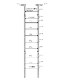
図1に、LTEにおける上りのSPSの処理シーケンスの一例を示す。ここでは上り(無線端末20から無線基地局10への無線通信)のSPSを説明するが、LTEにおいては下り(無線基地局10から無線端末20への無線通信)についても同様にSPSを適用することができる。
FIG. 1 shows an example of an upstream SPS processing sequence in LTE. Here, SPS in uplink (wireless communication from the
まず、図1のS101で無線基地局10は、SPSにおける基本的なパラメータを無線端末20に通知する。S101の通知は、L3(Layer 3)シグナリングであるRRC信号によって、物理下り共有チャネル(PDSCH: Physical Downlink Shared CHannel)を介して送受信される。S101のRRC信号で通知されるSPSのパラメータには、例えばSPSの通信間隔等を含む。無線基地局10は、SPSの通信間隔をサブフレーム(1msec)単位で設定することができる。なお、S101のRRC信号ではSPSの基本的なパラメータが通知されるのみであり、このRRC信号に基づくタイミングでSPSに基づく送受信が開始されるわけではない。
First, in S101 of FIG. 1, the radio base station 10 notifies the
次にS102で無線基地局10は、SPSを活性化(activation)するための制御信号を無線端末20に送信する。S102の制御信号は、L1(Layer 1)シグナリングであるDCI(Downlink Control Information)によって、物理下り制御チャネル(PDCCH: Physical Downlink Control CHannel)を介して送受信される。S102の制御信号により、S101のRRC信号で基本パラメータが設定されたSPSが活性化され、当該SPSに基づく送受信が開始される。S102の制御信号に相当するDCIは、SPSの実行に必要なパラメータを含む。DCIが含むパラメータは、SPSに基づく送信が行われる各サブフレームにおける上り物理共有チャネル(Physical Uplink Shared CHannel)に対応する無線リソースの指定や、SPSに基づく送信に適用される変調符号化方式(MCS: Modulation and Coding)の指定等を含む。
Next, in S102, the radio base station 10 transmits a control signal for activating SPS to the
そして、S103〜S109にかけて無線端末20は、特別なシグナリングを介さずに、SPSに基づく送信をPUSCHを介して行う。SPSに基づく初回の送信に当たるS103は、S102でDCIが送受信されたサブフレームの4サブフレーム後に行われる。以後、S101のRRC信号により通知された通信間隔毎のサブフレームにおいて、無線端末20は無線基地局10にSPSに基づく送信をPUSCHを介して行う。
Then, from S103 to S109, the
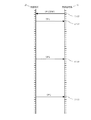
図2に、図1のS102〜S105に対応する拡大図を示す。図2は、一例として、SPSの通信間隔が20サブフレームである場合を図示している。図2に示されるように、上述した通り、SPSに基づく初回の送信に当たるS103は、S102でDCIを受信したサブフレームの4サブフレーム後に行われる。そして、その後は、通信間隔である20サブフレーム毎の各1サブフレームにおいて、無線端末20は無線基地局10にSPSに基づく送信を行う。
FIG. 2 shows an enlarged view corresponding to S102 to S105 in FIG. FIG. 2 illustrates a case where the SPS communication interval is 20 subframes as an example. As shown in FIG. 2, as described above, S103 corresponding to the first transmission based on SPS is performed after four subframes of the subframe in which DCI is received in S102. After that, the
図1に戻って、S110で無線基地局10は、SPSを解放(release)するための制御信号を無線端末20に送信する。S110の制御信号は、S102と同様に、DCIによってPDSCHを介して送受信される。S110の制御信号により、S103で活性化されたSPSが解放され、当該SPSに基づく送受信が終了される。これにより、S106以降、SPSに基づく送信は行われない。ただし、S106の後に無線基地局10が再びSPSを活性化した場合には、無線端末20はSPSに基づく送信を再び開始することができる。
Returning to FIG. 1, in S110, the radio base station 10 transmits a control signal for releasing the SPS to the
なお、図1においては一例として、SPSに基づく送信が7回以上(図中の省略を含む)行われた後に無線基地局10はSPSを開放しているが、無線基地局10は任意のタイミングでSPSを解放することができる。例えば無線基地局10は、SPSを利用するアプリケーション(VoIPによる通話等)が終了したタイミングで、SPSを解放することができる。 In FIG. 1, as an example, the radio base station 10 releases the SPS after transmission based on SPS is performed seven times or more (including omission in the figure). Can release SPS. For example, the radio base station 10 can release the SPS at the timing when an application (such as a VoIP call) using the SPS is completed.
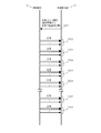
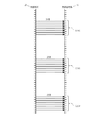
一方、図3にLTEにおける下りのSPSの処理シーケンスの一例を示す。また、図4に、図3のS202〜S205に対応する拡大図を示す。図1〜2に示される上りのSPSでは各送信(S103〜S109)をPUSCHを介して行っていたのに対し、図3〜4に示される下りのSPSにおいては、各送信(S203〜S209)をPDSCHを介して行う点が異なっている。 On the other hand, FIG. 3 shows an example of a processing sequence of downlink SPS in LTE. FIG. 4 shows an enlarged view corresponding to S202 to S205 in FIG. In the uplink SPS shown in FIGS. 1 and 2, each transmission (S103 to S109) is performed via the PUSCH, whereas in the downlink SPS shown in FIGS. 3 to 4, each transmission (S203 to S209). The difference is that it is performed via PDSCH.
図1〜4に基づいて説明したSPSによれば、ダイナミックスケジューリングのようにデータ送信の度に無線リソースの割当のためのシグナリングを行う必要が無くなる。例えば図1のS103〜S109に示されるような送信を、ダイナミックスケジューリングによって行おうすると、S103〜S109のそれぞれの送信毎にリソース割当のためのシグナリングが必要となる。これに対し、図1に示されるSPSにおいては、S103〜S109のそれぞれの送信毎にリソース割当のためのシグナリングは必要ない。図1に示されるSPSにおいて必要なシグナリングは、SPSに基づく送信を開始するためのS101およびS102と、SPSに基づく送信を終了させるためのS110のみとなる。したがって、SPSによれば、ダイナミックスケジューリングと比較してシグナリング量を抑制することが可能となる。シグナリング量の抑制の効果は、SPSの送信回数が増える(または、SPSの実行期間が長くなる)ほどに、高まると考えられる。 The SPS described with reference to FIGS. 1 to 4 eliminates the need for signaling for radio resource allocation each time data is transmitted as in dynamic scheduling. For example, if transmission as shown in S103 to S109 of FIG. 1 is performed by dynamic scheduling, signaling for resource allocation is required for each transmission of S103 to S109. On the other hand, in the SPS shown in FIG. 1, signaling for resource allocation is not required for each transmission of S103 to S109. Signals required in the SPS shown in FIG. 1 are only S101 and S102 for starting transmission based on the SPS and S110 for terminating transmission based on the SPS. Therefore, according to SPS, it becomes possible to suppress the amount of signaling compared with dynamic scheduling. The effect of suppressing the signaling amount is considered to increase as the number of SPS transmissions increases (or the SPS execution period becomes longer).
一方、SPSには、ダイナミックスケジューリングとの比較において、デメリットも存在する。SPSのデメリットの一つとして、ダイナミックスケジューリングと比較して、無線環境の変化に弱いことが挙げられる。このデメリットは、前述した適応的変調符号化がSPSには適用できないことを起因とするものである。適応的変調符号化は、通信の度に無線環境に応じたMCSの指定を行うことにより実現されるため、通信の度にMCSを通知するためのシグナリングが必要となる。しかしながら、SPSは通信の度のシグナリングを省略するため、適応的変調符号化を適用することが本来的に不可能である。そのため、SPSにおいては、活性化時(図1のS102)に指定されたMCSを解放時(図1のS110)まで使い続ける。そのため、SPSにおいては、活性化後に例えば無線環境が悪化した場合に、誤りに強いMCSに変更することはできない。したがって、SPSは無線環境の変化に弱いという性質がある。もし誤りに強いMCSに変更したい場合は、SPSの再活性化(re-activation)を行う必要がある。SPSの再活性化の際には、SPSの活性化(activation)の場合と同様に、SPSの実行に必要なパラメータを含む。DCIが含むパラメータは、SPSに基づく送信が行われる各サブフレームにおける上り物理共有チャネル(Physical Uplink Shared CHannel)に対応する無線リソースの指定や、SPSに基づく送信に適用される変調符号化方式(MCS: Modulation and Coding)の指定等を含む。 On the other hand, SPS also has disadvantages in comparison with dynamic scheduling. One of the disadvantages of SPS is that it is vulnerable to changes in the wireless environment compared to dynamic scheduling. This demerit is due to the fact that the adaptive modulation and coding described above cannot be applied to SPS. Since adaptive modulation and coding is realized by specifying MCS in accordance with the radio environment for each communication, signaling for notifying MCS is required for each communication. However, since SPS omits signaling at every communication, it is inherently impossible to apply adaptive modulation and coding. Therefore, in the SPS, the MCS designated at the time of activation (S102 in FIG. 1) is continuously used until it is released (S110 in FIG. 1). Therefore, in the SPS, for example, when the wireless environment deteriorates after activation, it cannot be changed to an MCS that is resistant to errors. Therefore, SPS has the property of being vulnerable to changes in the wireless environment. If you want to change to an MCS that is resistant to errors, you need to re-activate the SPS. When the SPS is reactivated, the parameters necessary for executing the SPS are included as in the case of SPS activation. The parameters included in DCI are the radio resource designation corresponding to the uplink physical shared channel (Physical Uplink Shared CHannel) in each subframe in which transmission based on SPS is performed, and the modulation and coding scheme (MCS) applied to transmission based on SPS. : Modulation and Coding).
ここで、MTCデバイスに対するスケジューリングに話を戻すと、MTCデバイスは上記で説明したSPSと比較的相性が良いと考えられる。まず、上述したようにSPSには適応的変調符号化は適用されないが、移動に基づく無線品質の変化がほとんどないMTCデバイスに対してはその弊害は少ないと考えられる。また、SPSは上りの場合であっても、シグナリングは最初と最後のみであり、ダイナミックスケジューリングのように上りデータの送信の度にシグナリングが送受信されることはない。したがって、MTCデバイスが送受するシグナリング量を抑えることができる。 Here, returning to the scheduling for the MTC device, it is considered that the MTC device is relatively compatible with the SPS described above. First, as described above, adaptive modulation and coding is not applied to SPS, but it is considered that the adverse effect is small for an MTC device that hardly changes in radio quality due to movement. Even if the SPS is uplink, the signaling is only at the beginning and the end, and signaling is not transmitted / received every time uplink data is transmitted unlike dynamic scheduling. Therefore, the amount of signaling transmitted and received by the MTC device can be suppressed.
以上のように、MTCデバイスにSPSを適用した場合、SPSのデメリットによる影響をほとんど受けることなく、SPSのメリットを享受できると考えられる。したがって、MTCデバイスはSPSと好相性であり、MTCデバイスにはSPSを適用してスケジューリングを行うのが望ましいと考えられる。 As described above, when the SPS is applied to the MTC device, it is considered that the advantages of the SPS can be enjoyed almost without being affected by the disadvantages of the SPS. Therefore, it is considered that the MTC device has good compatibility with the SPS, and it is desirable to perform scheduling by applying the SPS to the MTC device.
ところで、SPSは従来、前述したようなVoIP等に適用されることが想定されていた。ここで、VoIPに基づく通話データは、音声データであるため、1回の送信あたりのデータ量はそれほど大きくないと考えられる。 By the way, SPS has been conventionally assumed to be applied to VoIP as described above. Here, since the call data based on VoIP is voice data, the amount of data per transmission is not so large.
これに対し、今後は、MTCデバイスにSPSを適用した場合等において、比較的大きな動画や静止画等のデータを送受信することも想定される。一例として、MTCに対応した監視カメラにSPSを適用することを考える。監視カメラは所定の周期で撮影した画像を、SPSに基づく所定の通信間隔(例えば80msec)でサーバに送信する。このような場合には、SPSの毎回の送信において、比較的大きなデータが送受信されることになる。 On the other hand, in the future, when SPS is applied to the MTC device, data such as relatively large moving images and still images may be transmitted and received. As an example, consider applying SPS to a surveillance camera compatible with MTC. The monitoring camera transmits images taken at a predetermined cycle to the server at a predetermined communication interval (for example, 80 msec) based on SPS. In such a case, relatively large data is transmitted and received in each transmission of the SPS.
ここで、無線端末20が比較的大きなデータを送る場合には、比較的大きな無線リソースを無線端末20に割当てる必要がある。これを従来のSPSにおいて実現しようとすると、SPSの送信タイミングにあたる1サブフレームにおいて、比較的大きな無線リソースを割当てる必要がある。この場合、SPSの送信タイミングにあたる1サブフレーム毎に比較的大きな無線リソースが、特定の無線端末20に対し半持続的に予約されることになる。しかしながら、将来のサブフレームにおいて比較的大きな無線リソースを特定の無線端末20に割当ててしまうと、他の無線端末20の当該サブフレームにおける無線リソース割当の柔軟性を予め奪うことになるため、好ましくない。
Here, when the
例えば、SPSを実施する無線端末20が多くなると、SPS用の無線リソースにより、あるサブフレームが圧迫されることも起こりうる。このような場合に、SPS用の無線リソースで圧迫されたサブフレームにおいて、優先度や緊急性が高いSPS以外のデータ送信が発生すると、対応が困難となることが想定される。特に、今後のMTCデバイスの広まり等により無線端末20の台数が増加することを考慮すると、無線リソースの割当の柔軟性はできるだけ確保しておくべきであると考えられる。
For example, when the number of
また、上記の事情に加え、MTCデバイスは、例えばセンサーネットワークにおける各種のセンサー装置のように、サイズの小さいデータが多発的に発生するという特性があるものも多いと考えられる。このようなMTCデバイスにおいては、図1〜4に示されるようなone-shot型のSPSでは、無線リソースの割当が不十分となりうることも懸念される。また、このようなMTCデバイスに対し、送信するデータをある程度バッファリングする前提でone-shot型のSPSを適用することも可能と思われる。しかしながら、MTCデバイスに搭載されるメモリは容量が小さい場合も多く、それほど多くのデータはバッファリングできないため、やはりMTCデバイスとone-shot型のSPSとはそれほど相性が良くないと考えられる。 In addition to the above circumstances, it is considered that many MTC devices, such as various sensor devices in a sensor network, have a characteristic that small-sized data is frequently generated. In such an MTC device, there is a concern that radio resource allocation may be insufficient in the one-shot type SPS as shown in FIGS. It is also possible to apply a one-shot type SPS to such an MTC device on the premise that data to be transmitted is buffered to some extent. However, the memory installed in the MTC device often has a small capacity, and so much data cannot be buffered, so it is still considered that the MTC device and the one-shot type SPS are not so compatible.
なお、以上の説明は例としてMTCデバイスに基づいて行ったが、上記の問題は必ずしもMTCデバイスに限られるものではない。上記の問題は、例えばMTCデバイスと同様なもしくは類似した形態で利用される通常の携帯電話端末についても起こりうるものであると考えられる。 Although the above description has been made based on an MTC device as an example, the above problem is not necessarily limited to the MTC device. It is considered that the above-described problem may also occur with a normal mobile phone terminal that is used in the same or similar form as the MTC device, for example.
以上をまとめると、従来のSPSにおいては、画像データのような比較的大きなデータを送受信することは想定されていなかったと考えられる。そのため、監視カメラ等のMTCデバイスを含む携帯電話端末に従来のSPSがそのまま適用されると、将来の無線リソースの割当における柔軟性が失われるという不都合が生じる可能性がある。また、MTCデバイスでは、小さなデータが多発的に発生するという特徴を有するため、従来のone-shot型のSPSにおいては、対応するのが難しい。前述したようにこの問題は、発明者が従来技術を仔細に検討した結果として新たに見出したものであり、従来は知られていなかったものである。以降では、この問題を解決するための本願の各実施形態を順に説明する。 In summary, it is considered that the conventional SPS was not supposed to transmit / receive relatively large data such as image data. Therefore, when the conventional SPS is applied as it is to a mobile phone terminal including an MTC device such as a surveillance camera, there is a possibility that the flexibility in allocating future radio resources is lost. In addition, since the MTC device has a feature that small data is frequently generated, it is difficult to cope with the conventional one-shot type SPS. As described above, this problem was newly found as a result of careful study of the prior art by the inventor, and has not been known so far. Hereinafter, each embodiment of the present application for solving this problem will be described in order.
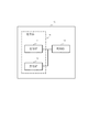
[第1実施形態]
第1実施形態は、無線基地局10が無線端末20に対し、所定の通信間隔で行われる通信の通信間隔とともに、各通信間隔で前記通信を行うための通信区間を指定するものである。言い換えれば、複数個の区間から成る通信間隔で行われる通信における該通信間隔を含む第1情報を無線基地局から受信する受信部と、前記第1情報に基づいて、前記無線基地局と前記通信を行う通信部とを備え、前記第1情報は、前記複数個の区間のうちの所定個の区間で前記通信を行うことを示す第2情報を含む無線端末20及びこれを含む無線通信システム等に対応するものである。[First Embodiment]
In the first embodiment, the radio base station 10 specifies a communication section for performing the communication at each communication interval together with a communication interval of communication performed at a predetermined communication interval with respect to the
第1実施形態の無線通信システムの前提を述べる。第1実施形態の無線通信システムが使用する無線リソースは少なくとも時間成分を有しており、ここでは便宜上、時間成分の単位を通信区間と呼ぶことにする。無線基地局10および無線端末20は、時間方向では通信区間単位で送信や受信を行うことができるものとする。なお、ここで「通信区間」とは無線リソースの時間成分の単位を示す用語の一例にすぎず、これを例えば、フレーム、サブフレーム、スロット、タイムスロット、あるいは(単に)区間、等の用語と置換しても本願発明の本質は何ら損なわれないことは言うまでもない。
The premise of the radio | wireless communications system of 1st Embodiment is described. The radio resource used by the radio communication system according to the first embodiment has at least a time component. Here, for convenience, the unit of the time component is referred to as a communication section. It is assumed that the radio base station 10 and the
また、第1実施形態においては、通信間隔を有する上り送信(無線端末20から無線基地局10への、通信間隔を有する送信)に本願発明を適用した場合に基づいて説明を行う。しかしながら、本願発明は通信間隔を有する下り送信(無線基地局10から無線端末20への、通信間隔を有する送信)に対しても同様に適用することができることに留意する。
In the first embodiment, description will be made based on the case where the present invention is applied to uplink transmission having a communication interval (transmission having a communication interval from the
図5に、第1実施形態に係る無線通信システムの処理シーケンスの一例を示す。 FIG. 5 shows an example of a processing sequence of the wireless communication system according to the first embodiment.
S301で無線基地局10は、無線端末20による通信間隔を有する送信用の無線リソースの割当を当該無線端末20に対して行う。通信間隔を有する送信用の無線リソースの割当は、無線基地局10が、通信間隔を有する送信用の無線リソースを示す情報(以後は便宜上、リソース情報と称する)を無線端末20に送信することで行われる。
In step S <b> 301, the radio base station 10 assigns radio resources for transmission having a communication interval with the
ここで、リソース情報は、無線リソースの通信間隔を示す情報を少なくとも含むものとする。無線リソースの通信間隔を示す情報は、例えば、通信区間数(2以上の正整数であるNとする)とすることができる。 Here, the resource information includes at least information indicating a communication interval of radio resources. The information indicating the communication interval of the radio resource can be, for example, the number of communication sections (N being a positive integer of 2 or more).
さらに、リソース情報は、各通信間隔(各N通信区間)において無線リソースが割当てられた通信区間を示す情報(以後は便宜上、通信区間指示情報と称する)をも、少なくとも含む情報とする。通信区間指示情報は、各通信間隔(各N通信区間)において無線端末20が送信可能な通信区間を示す情報と言い換えることもできる。通信区間指示情報としては、いくつかの例が考えられる。例えば、各通信間隔において通信間隔を有する送信用の無線リソースは連続する通信区間上に割当てられるという前提を置く場合には、通信区間指示情報は、当該連続する通信区間の数(1以上でN−1以下の正整数であるMとする)とすることができる。
Furthermore, the resource information is information including at least information indicating a communication section to which a radio resource is allocated in each communication interval (each N communication section) (hereinafter referred to as communication section instruction information for convenience). The communication section instruction information can be paraphrased as information indicating a communication section that can be transmitted by the
一方、前記の前提を置かず、各通信間隔において通信間隔を有する送信用の無線リソースは連続しない通信区間上に割当てることもできるようにしてもよい。この場合の一例としては、通信区間指示情報を、Nビットのビットマップとすることができる。Nビットのビットマップにおける各ビットが、各通信間隔に相当するN個の通信区間それぞれにおける無線リソース割当の有無を示すことになる。なお、Nビットのビットマップを採用する場合には、ビットマップの長さが通信間隔を示すことになるため、リソース情報に通信間隔を示す別途の情報を含むことを要しない。 On the other hand, without making the above-mentioned assumption, a radio resource for transmission having a communication interval in each communication interval may be allocated on a non-continuous communication section. As an example of this case, the communication section instruction information can be an N-bit bitmap. Each bit in the N-bit bitmap indicates the presence / absence of radio resource allocation in each of N communication sections corresponding to each communication interval. Note that when an N-bit bitmap is employed, the length of the bitmap indicates the communication interval, so that it is not necessary to include additional information indicating the communication interval in the resource information.
また、S301で無線基地局10が送信するリソース情報としては、前述した通信間隔を示す情報や通信区間指示情報以外の、通信間隔を有する送信に用いる無線リソースに関する情報を含んでもよい。例えば、リソース情報は、通信区間指示情報で示される通信区間に割当てられた無線リソースを特定するための情報(例えば、周波数情報や時間情報)を含むようにしてもよい。また、リソース情報は、通信間隔を有する送信における初回送信のタイミングを示す情報(例えば、通信区間のオフセット情報)を含んでもよい。 Further, the resource information transmitted by the radio base station 10 in S301 may include information on radio resources used for transmission having a communication interval other than the information indicating the communication interval and the communication section instruction information described above. For example, the resource information may include information (for example, frequency information and time information) for specifying a radio resource allocated to the communication section indicated by the communication section instruction information. Further, the resource information may include information indicating the timing of initial transmission in transmission having a communication interval (for example, communication section offset information).
次にS302〜S308のそれぞれで無線端末20は、S301で割当てられた通信間隔を有する無線リソースに基づいて、無線基地局10に対する送信を行う。別の言い方をすれば、S302〜S308のそれぞれで無線端末20は、S301で受信したリソース情報に基づいて、無線基地局10に対して通信間隔を有する送信を行う。ここで、前述したように、リソース情報は少なくとも通信間隔を示す情報と通信区間指示情報とを含む。そのため、S302〜S308のそれぞれで無線端末20は、S301で受信したリソース情報に含まれる通信間隔を示す情報と通信区間指示情報とで特定される通信区間において、無線基地局10に対して通信間隔を有する送信を行う。
Next, in each of S302 to S308, the
図6に、図5のS302〜S304に対応する拡大図を示す。図6は、一例として、無線端末20が行う送信における通信間隔Nが20通信区間の場合を示している。また、図6は、一例として、各通信間隔において通信用の無線リソースは連続する通信区間上に配置されるという前提を置いた上で、通信区間指示情報が示す当該連続する通信区間の数Mが8の場合を示している。このとき、図6のS302〜S304に示されるように、20通信区間の通信間隔で、各通信間隔において連続する8通信区間において、無線端末20は無線基地局10に送信を行うことができる。
FIG. 6 shows an enlarged view corresponding to S302 to S304 in FIG. FIG. 6 shows, as an example, a case where the communication interval N in transmission performed by the
以上説明した第1実施形態に係る無線通信システムによれば、無線基地局10が通信間隔を有する送信用の無線リソースを割当てる際に、各通信間隔において複数通信区間に跨る無線リソースを割当てることが可能となる。これにより、通信間隔を有する送信における無線リソースの割当を時間方向で柔軟に行うことが可能となる。 According to the radio communication system according to the first embodiment described above, when the radio base station 10 allocates radio resources for transmission having a communication interval, radio resources over a plurality of communication intervals can be allocated in each communication interval. It becomes possible. This makes it possible to flexibly allocate radio resources in the time direction in transmissions having communication intervals.
これにより、第1実施形態によれば、通信間隔を有する送信を行う場合において、各通信間隔に比較的大きなデータを送信する場合に、複数の通信区間に分割して送信することが可能となる。そのため、複数の通信区間において予め確保しておく無線リソースが小さくなる。その結果、通信間隔を有する送信において、ある通信区間の無線リソースが圧迫されるような場合が少なくなり、上述した問題を解決することができる。 Thereby, according to 1st Embodiment, when performing transmission which has a communication interval, when comparatively big data are transmitted to each communication interval, it becomes possible to divide | segment and transmit to a several communication area. . Therefore, the radio resources reserved in advance in a plurality of communication sections are reduced. As a result, in the transmission having the communication interval, the case where the radio resource in a certain communication section is compressed is reduced, and the above-described problem can be solved.
さらに第1実施形態は、図1等に例示される従来の通信間隔を有する送信と比較して、シグナリングの量を増やすことなく実現することができる。また、第1実施形態をダイナミックスケジューリングと比較すると、従来の通信間隔を有する送信以上に大幅にシグナリングの量を低減することができる。例えば従来の通信間隔を有する送信を例示した図2の送信をダイナミックスケジューリングで実現しようとすると3回のシグナリングを要するのに対し、第1実施形態を例示した図6の送信をダイナミックスケジューリングで実現しようとすると24回ものシグナリングを要することからも、第1実施形態はシグナリング量低減の効果が大きいことが分かる。 Furthermore, the first embodiment can be realized without increasing the amount of signaling as compared with the transmission having the conventional communication interval illustrated in FIG. 1 and the like. In addition, when the first embodiment is compared with dynamic scheduling, the amount of signaling can be significantly reduced over the transmission having the conventional communication interval. For example, when the transmission of FIG. 2 exemplifying the transmission having the conventional communication interval is realized by the dynamic scheduling, the signaling of 3 times is required, whereas the transmission of FIG. 6 exemplifying the first embodiment is realized by the dynamic scheduling. Then, it can be understood that the first embodiment has a great effect of reducing the signaling amount because 24 times of signaling is required.
これらに加えて、第1実施形態によれば、各通信間隔で送るべきデータを複数通信区間に分割して送信することができる。これにより、送信電力を一定とすると、ビット当たりの送信電力が相対的に増えるため、カバレッジが向上する。別の言い方をすると、誤りに強い変調方式・符号化方式を使用できるため、通信特性が向上するという効果が得られる。 In addition to these, according to the first embodiment, data to be sent at each communication interval can be divided into a plurality of communication sections and transmitted. As a result, when the transmission power is constant, the transmission power per bit is relatively increased, so that the coverage is improved. In other words, it is possible to use a modulation scheme / coding scheme that is resistant to errors, so that an effect of improving communication characteristics can be obtained.
[第2実施形態]
第2実施形態は、LTEのSPS(Semi-Persistent Scheduling)送信に対して本願発明を適用した場合に対応する実施形態である。一言で言うと、図1〜4に示される従来のSPSはone-shot型であるのに対し、第2実施形態のSPSはmulti-shot型のSPSを実現するものである。[Second Embodiment]
The second embodiment is an embodiment corresponding to a case where the present invention is applied to LTE SPS (Semi-Persistent Scheduling) transmission. In short, the conventional SPS shown in FIGS. 1 to 4 is a one-shot type, whereas the SPS of the second embodiment realizes a multi-shot type SPS.
第2実施形態においても、上りのSPS送信に本願発明を適用した場合に基づいて説明を行う。しかしながら、本願発明は下りのSPS送信に対しても同様に適用することができることに留意する。 Also in the second embodiment, description will be made based on the case where the present invention is applied to uplink SPS transmission. However, it should be noted that the present invention can be similarly applied to downlink SPS transmission.
第2実施形態の無線通信システムの前提を述べる。無線リソースは時間成分を有しており、時間成分の単位をサブフレーム(1msec)である。無線基地局10および無線端末20は、時間方向ではサブフレーム単位で送信や受信を行うことができるものとする。
The premise of the radio | wireless communications system of 2nd Embodiment is described. The radio resource has a time component, and the unit of the time component is a subframe (1 msec). It is assumed that the radio base station 10 and the
図7に、第2実施形態に係る無線通信システムの処理シーケンスの一例を示す。 FIG. 7 shows an example of a processing sequence of the wireless communication system according to the second embodiment.
S401で無線基地局10は、SPSのパラメータを含むRRC信号を無線端末20に対して送信する。より具体的には、無線基地局10が無線端末20に送信するRRC信号であるRRCConnectionSetupメッセージ、RRCConnectionReconfigurationメッセージ、またはRRCConnectionReestablishmentメッセージは、それぞれRadioResourceConfigDedicated情報要素を含んでいる。そしてRadioResourceConfigDedicated情報要素はSPS-Config情報要素を含むことができる。このSPS-Config情報要素が、SPSに関する各種のパラメータを含んでいる。したがって、S401で無線基地局10は、RRCConnectionSetupメッセージ、RRCConnectionReconfigurationメッセージ、またはRRCConnectionReestablishmentメッセージのいずれかにSPS-Configを格納して無線端末20に送信する。
In step S <b> 401, the radio base station 10 transmits an RRC signal including SPS parameters to the
ここで、比較のために、まず従来のLTEシステムにおけるSPS-Config情報要素を説明する。まず、SPS-Config情報要素は、パラメータであるsemiPersistSchedC-RNTI、sps-ConfigDL情報要素、sps-ConfigUL情報要素を含んでいる。ここで、semiPersistSchedC-RNTIは、SPSにおける無線端末20の識別子に相当し、前述したDCIが自分宛であるか否かを判定する際に用いる。また、sps-ConfigDL情報要素とsps-ConfigUL情報要素とは、それぞれ下りのSPSと上りのSPSに対する各種パラメータを含んでいる。以下では、sps-ConfigUL情報要素に基づいて説明を行うが、sps-ConfigDL情報要素も概ね同様に扱うことができる。
Here, for comparison, the SPS-Config information element in the conventional LTE system will be described first. First, the SPS-Config information element includes the parameters semiPersistSchedC-RNTI, sps-ConfigDL information element, and sps-ConfigUL information element. Here, semiPersistSchedC-RNTI corresponds to the identifier of the
図8に従来のLTEシステムにおけるsps-ConfigUL情報要素を示す。SPS-ConfigUL情報要素はSPSに関するいくつかのパラメータを含んでおり、その一つであるsemiPersistSchedulingIntervalULが上りのSPSの通信間隔を示すパラメータである。semiPersistSchedulingIntervalULは、それぞれ10、20、32、40、64、80、128、160、320、または640サブフレームの各値を取りうることが規定されている。したがって、無線基地局10は、これらの値のいずれかをsemiPersistSchedulingIntervalULに設定したRRC信号を送信することで、無線端末20に上りのSPSの通信間隔を通知することができる。
FIG. 8 shows sps-ConfigUL information elements in the conventional LTE system. The SPS-ConfigUL information element includes several parameters related to SPS, and one of them, semiPersistSchedulingIntervalUL, is a parameter indicating an uplink SPS communication interval. It is defined that semiPersistSchedulingIntervalUL can take values of 10, 20, 32, 40, 64, 80, 128, 160, 320, or 640 subframes, respectively. Therefore, the radio base station 10 can notify the
これに対し、図9に第2実施形態におけるSPS-ConfigUL情報要素を示す。図9のSPS-ConfigUL情報要素は、図8とは異なり、パラメータとの一つとしてsemiPersistSchedulingTransmissionPeriodULを含んでいる(下線部)。ここでsemiPersistSchedulingTransmissionPeriodULは、上りのSPSの各通信間隔において送信可能な連続するサブフレームの数を表すパラメータとする。ここでは、一例として、第1実施形態で説明したのと同様に、SPSの各通信間隔においては連続するサブフレームにおいてのみ送信可能であるという前提を置くものとしている。 On the other hand, FIG. 9 shows an SPS-ConfigUL information element in the second embodiment. The SPS-ConfigUL information element in FIG. 9 includes semiPersistSchedulingTransmissionPeriodUL as one of the parameters unlike FIG. 8 (underlined portion). Here, semiPersistSchedulingTransmissionPeriodUL is a parameter representing the number of consecutive subframes that can be transmitted in each communication interval of the uplink SPS. Here, as an example, as described in the first embodiment, it is assumed that transmission is possible only in consecutive subframes in each communication interval of SPS.
図9のsemiPersistSchedulingTransmissionPeriodULは、一例として3ビットの情報であるとする。また、3ビットに基づく000〜111の8種類の値により、semiPersistSchedulingTransmissionPeriodULは、上りのSPSの各通信間隔において送信可能な連続するサブフレームの数として1、2、4、8、16、32、64、128を表すことができるものとする。 The semiPersistSchedulingTransmissionPeriodUL in FIG. 9 is assumed to be 3-bit information as an example. In addition, semiPersistSchedulingTransmissionPeriodUL has 1, 2, 4, 8, 16, 32, 64 as the number of consecutive subframes that can be transmitted in each upstream SPS communication interval by eight values of 000 to 111 based on 3 bits. , 128 can be represented.
以上をまとめると、S401で無線基地局10は、SPSの通信間隔を示す情報(semiPersistSchedulingIntervalUL)とSPSの各通信間隔において送信可能な連続するサブフレームの数を表す情報(semiPersistSchedulingTransmissionPeriodUL)を含むRRC信号を無線端末20に対して送信する。一方、無線端末20は無線基地局10が送信したRRC信号を受信する。
In summary, in S401, the radio base station 10 receives an RRC signal including information indicating the SPS communication interval (semiPersistSchedulingIntervalUL) and information indicating the number of consecutive subframes that can be transmitted in each SPS communication interval (semiPersistSchedulingTransmissionPeriodUL). Transmit to the
次にS402で無線基地局10は、SPSを活性化するための制御信号を無線端末20に対して送信する。より具体的には、無線基地局10は、下りの制御情報であるDCI(Down link Information)に含まれる所定のパラメータに所定の値を設定したうえで無線端末20に送信することで、SRSを活性化する。ここで、SPSの活性化(activation)とは、S301で設定されたパラメータに基づくSPSを開始することに相当する。
Next, in S402, the radio base station 10 transmits a control signal for activating SPS to the
本実施形態におけるDCIは、一般的なLTEにおけるDCIと同じものを用いることができる。図10A〜Bに本実施形態におけるDCIを示す。DCIはいくつかのフォーマットが規定されており、それぞれ役割が異なっている。上りのSPSを活性化する場合、DCI format 0を用いる。DCI format 0は、上りデータのダイナミックスケジューリングに使用される制御情報であるが、上りSPSの活性化にも使用される。DCI format 0は、NDI、TPC command for scheduled PDSCH、Cyclic shift RM RS、MCS and RV、Resource Block等の各フィールドを含む。
The DCI in the present embodiment can be the same as the DCI in general LTE. 10A and 10B show the DCI in this embodiment. DCI has several formats, each with a different role.
DCI format 0のこれらのフィールドの値を図10Aで示す表の「アクティベーション」の列が示す値に設定することで、無線基地局10は無線端末20に対して上りのSPSを活性化する旨を通知することができる。ここで、MCSフィールドは5ビットのフィールドであるが、最初の1ビットを0に設定し、残りの4ビットによりSPSで用いる変調符号化方式を指定する。また、Resource Blockは上りの帯域幅に応じて異なるサイズとなる(例えば、上りの帯域幅が50MHzの場合は6ビット、100MHzの場合は8ビットとなる)が、これによりSPSで送信を行う各サブフレームにおけるリソースブロック(上りの帯域幅を分割したもので、周波数方向のリソース単位)を指定することができる。
By setting the values of these fields of
一方、下りのSPSを活性化する場合、DCI format 1、1A、2、2A、2B、2Cのいずれかを用いる。これらのDCI format 0のこれらのフィールドの値を図10Bで示す表の「アクティベーション」の列が示す値に設定することで、無線基地局10は無線端末20に対して下りのSPSを活性化する旨を通知することができる。
On the other hand, when the downstream SPS is activated, one of
次に図7のS403〜S409で無線端末20は、SPSに基づく送信を行う。これらのSPS送信は、S401のRRC信号とS402のDCIとで通知された各種パラメータ等に基づいて実行される。
Next, in S403 to S409 of FIG. 7, the
図11に、図7のS402〜S405に対応する拡大図を示す。図2で説明したように、SPSに基づく初回の送信に当たるS403は、S402でDCIが送受信されたサブフレームの4サブフレーム後に行われる。この4サブフレームのタイミング差(FDDの場合)は、仕様で予め規定されている固定値であるため、無線基地局10から指示等を受けることなく、無線端末20はS402を受信したタイミングに基づいてSPSの初回送信のタイミングを認識することができる。 FIG. 11 shows an enlarged view corresponding to S402 to S405 in FIG. As described with reference to FIG. 2, S403 corresponding to the first transmission based on SPS is performed four subframes after the subframe in which DCI is transmitted and received in S402. The timing difference between the four subframes (in the case of FDD) is a fixed value defined in advance in the specification. The timing of the first transmission of SPS can be recognized.
そしてその後は、図11のS403〜S405や図7のS403〜S409に示されるように、S401のRRC信号により通知されたsemiPersistSchedulingIntervalULとsemiPersistSchedulingTransmissionPeriodULの値に基づいて、無線端末20は無線基地局10にSPSに基づく送信を行う。図11は、一例として、S401のRRC信号に含まれるsemiPersistSchedulingIntervalULの値が20サブフレームの場合を示している。また、図11は、一例として、S401のRRC信号に含まれるsemiPersistSchedulingTransmissionPeriodULの値が8サブフレームの場合を示している。このとき、図11のS403〜S405に示されるように、20サブフレームの通信間隔で、各通信間隔において連続する8サブフレームにおいて、無線端末20は無線基地局10に送信を行うことができる。
After that, as shown in S403 to S405 in FIG. 11 and S403 to S409 in FIG. Send based on. FIG. 11 shows an example in which the value of semiPersistSchedulingIntervalUL included in the RRC signal in S401 is 20 subframes. FIG. 11 shows an example in which the value of semiPersistSchedulingTransmissionPeriodUL included in the RRC signal in S401 is 8 subframes. At this time, as shown in S403 to S405 of FIG. 11, the
次に、各通信間隔における連続するサブフレームの送信(例えば、図11のS403に示されるような連続する8個のサブフレームの送信)の処理について詳しく説明する。ここでは、説明を単純化するために、前提として、無線端末20が各通信間隔で送信するデータが当該通信間隔の送信前に確定しているものとする。そして、各通信間隔において送信するデータを、semiPersistSchedulingTransmissionPeriodUL個のサブフレームで分割して送信するものとする。
Next, the process of transmitting consecutive subframes at each communication interval (for example, transmitting 8 consecutive subframes as shown in S403 of FIG. 11) will be described in detail. Here, in order to simplify the description, it is assumed that the data transmitted by the
無線端末20はS403等において、当該通信間隔で送信するデータをsemiPersistSchedulingTransmissionPeriodUL個に分割したデータを、連続するsemiPersistSchedulingTransmissionPeriodUL個のサブフレームそれぞれで送信する。図11の例では、無線端末20はS403等において、当該通信間隔で送信するデータを8個に分割したデータを、連続する8個のサブフレームそれぞれで送信する。このとき無線端末20は、semiPersistSchedulingTransmissionPeriodUL個のサブフレームそれぞれで、S402のDCIで指定されたMCSに基づいて分割データを符号化および変調する。また無線端末20は、semiPersistSchedulingTransmissionPeriodUL個のサブフレームそれぞれで、S402のDCIで指定されたResource Blockに対して、符号化および変調された分割データをマッピングする。以上のようにして、無線端末20はS403等に対応するSPSに基づく送信を行うことができる。
In S403 and the like, the
ところで、LTEシステムでは再送制御が行われる。そのため、無線基地局10はデータを受信すると、応答信号であるACK信号またはNACK信号を無線端末20に送信する。ACK信号はデータの受信(復号)に成功したことを示す応答信号である。一方、NACK信号はデータの受信(復号)に失敗したことを示す応答信号である。無線端末20はこれらの応答信号に基づき、データの再送を行うか否かを決定する。LTEシステムにおいては、データを受信したサブフレームの4個後のサブフレームにおいて、ACK信号またはNACK信号を送信することが規定されている。
By the way, retransmission control is performed in the LTE system. Therefore, when the radio base station 10 receives data, the radio base station 10 transmits an ACK signal or a NACK signal as a response signal to the
図7および図11において各データに対するACK信号及びNACK信号は図示されていないが、本実施形態の無線基地局10は受信結果に応じてACK信号またはNACK信号を無線端末20に送信するものとする。ACK信号やNACK信号の送信においてはいくつかの方式が考えられる。最も単純な方式としては、一般的なLTEシステムに則って、サブフレーム毎にACK信号またはNACK信号を送信することができる(便宜上、個別応答方式と呼ぶ)。個別応答方式では再送もサブフレーム毎に行うことができる。個別応答方式によれば、図11に示す場合、各通信間隔でSPS送信される8個のサブフレームそれぞれについて、無線基地局10はACK信号またはNACK信号を無線端末20に送信する必要がある。つまり図11の例では、SPS送信の各通信間隔に8個のACK信号またはNACK信号を要することになる。
Although the ACK signal and NACK signal for each data are not shown in FIG. 7 and FIG. 11, the radio base station 10 of this embodiment transmits an ACK signal or a NACK signal to the
このようにサブフレーム毎にACK信号またはNACK信号を送信する個別応答方式は、既存のLTEシステムに馴染みやすいものの、シグナリング量が膨大となる懸念がある。そこで、各通信間隔毎に1つのACK信号またはNACK信号を送信する方式が考えられる(便宜上、一括応答方式と呼ぶ)。図11の例に基づいて説明すると、無線基地局10は、各通信間隔で通信可能な最後(8個目)のサブフレームまで受信した後に、当該通信間隔で通信可能な全てのサブフレームの受信が成功した場合にはACKを1回だけ送信する。一方、無線基地局10は当該通信間隔で通信可能なサブフレームの受信が1つでも失敗した場合にはNACKを1回だけ送信する。しかし、一括応答方式の場合、再送が必要な場合、8個のサブフレームをまとめて再送する必要がある。そのためシグナリング量は減るが、再送するデータ量が増えてしまうという別の問題が発生する。 As described above, although the individual response method for transmitting the ACK signal or the NACK signal for each subframe is easy to be familiar with the existing LTE system, there is a concern that the amount of signaling becomes enormous. Therefore, a method of transmitting one ACK signal or NACK signal at each communication interval is considered (for convenience, it is called a batch response method). Explaining based on the example of FIG. 11, the radio base station 10 receives all the subframes communicable in the communication interval after receiving the last (eighth) subframe communicable in each communication interval. If succeeds, send ACK only once. On the other hand, the radio base station 10 transmits NACK only once when reception of one subframe that can be communicated at the communication interval fails. However, in the case of the collective response method, when retransmission is necessary, it is necessary to retransmit 8 subframes collectively. Therefore, although the amount of signaling decreases, another problem that the amount of data to be retransmitted increases.
そこで、個別応答方式と一括応答方式を組み合わせた再送方式が考えられる。例えば、無線基地局10はある通信間隔で送信可能な全てのサブフレームの受信が成功した場合にはACKを最後に1回だけ送信する。一方、無線基地局10は当該通信間隔で送信可能なサブフレームのいずれかで受信が失敗した場合にはそのサブフレーム以降はサブフレーム毎にACK信号またはNACK信号を送信することができる。こうすると、シグナリング量を抑えることができるとともに、再送をサブフレーム毎に行うことが可能となる。 Therefore, a retransmission method combining an individual response method and a batch response method is conceivable. For example, when all the subframes that can be transmitted at a certain communication interval are successfully received, the radio base station 10 transmits ACK only once at the end. On the other hand, when reception fails in any of the subframes that can be transmitted at the communication interval, the radio base station 10 can transmit an ACK signal or a NACK signal for each subframe after that subframe. In this way, the amount of signaling can be suppressed, and retransmission can be performed for each subframe.
あるいは、ACK信号またはNACK信号は1ビットの信号であるが、これを複数ビットに拡張することも考えられる。例えばACK信号またはNACK信号を8ビットのビットマップとし、図2における各通信間隔において送信可能な8サブフレームの各サブフレームの受信結果に対応付けることができる。この方法でも、シグナリング量を抑制しながらサブフレーム毎の再送が可能である。 Alternatively, the ACK signal or the NACK signal is a 1-bit signal, but it may be possible to extend it to a plurality of bits. For example, an ACK signal or a NACK signal can be used as an 8-bit bitmap, and can be associated with reception results of 8 subframes that can be transmitted in each communication interval in FIG. Even in this method, retransmission for each subframe is possible while suppressing the amount of signaling.
なお、再送を行う場合には、無線端末20はダイナミックスケジューリングに基づいて無線基地局10から割当てられた無線リソースを用いて再送を行うことができる。また、次の通信間隔の無線リソースを用いて再送を行うこともできる。
Note that, when performing retransmission, the
最後に、上記で説明した第2実施形態においては、一例として、SPS送信の各通信間隔においては連続するサブフレームにおいてのみ送信可能であるという前提を置いた場合を説明している。しかしながら、この前提は第2実施形態(以降で説明する第2実施形態に基づく他の実施形態も含む)において必須のものではない。すなわち、第2実施形態においては、SPS送信の各通信間隔において連続しないサブフレームにおいて送信可能としてもよい。 Finally, in the second embodiment described above, as an example, a case has been described in which it is assumed that transmission is possible only in consecutive subframes in each communication interval of SPS transmission. However, this premise is not essential in the second embodiment (including other embodiments based on the second embodiment described below). That is, in the second embodiment, transmission may be possible in subframes that are not continuous in each communication interval of SPS transmission.
具体的には、上記説明においてはSPS送信のパラメータsemiPersistSchedulingTransmissionPeriodULは上りのSPSの各通信間隔において送信可能な連続するサブフレームの数を表すものとしたが、これに限られない。一例としては、semiPersistSchedulingTransmissionPeriodULを、SPS送信の通信間隔(サブフレーム単位)分のビット数から成るビットマップとすることができる。このとき、semiPersistSchedulingTransmissionPeriodULにおいて、ビットマップにおける各ビットが、各通信間隔において通信可能なサブフレームそれぞれにおける無線リソース割当の有無を示すことになる。また、semiPersistSchedulingTransmissionPeriodULを所定のビット数から成るビットマップとして、当該ビットマップにおける各ビットが、各通信間隔における先頭から所定ビット数のサブフレームそれぞれにおける無線リソース割当の有無を示すこととしてもよい。 Specifically, in the above description, the SPS transmission parameter semiPersistSchedulingTransmissionPeriodUL represents the number of consecutive subframes that can be transmitted in each uplink SPS communication interval, but is not limited thereto. As an example, semiPersistSchedulingTransmissionPeriodUL can be a bitmap consisting of the number of bits corresponding to the communication interval (subframe unit) of SPS transmission. At this time, in semiPersistSchedulingTransmissionPeriodUL, each bit in the bitmap indicates the presence / absence of radio resource allocation in each subframe that can be communicated in each communication interval. Also, semiPersistSchedulingTransmissionPeriodUL may be a bitmap consisting of a predetermined number of bits, and each bit in the bitmap may indicate the presence or absence of radio resource allocation in each subframe of a predetermined number of bits from the beginning in each communication interval.
以上説明した第2実施形態によれば、第1実施形態と同様の各種効果が得られる。 According to the second embodiment described above, various effects similar to those of the first embodiment can be obtained.
すなわち、第2実施形態に係る無線通信システムによれば、無線基地局10がSPS用の無線リソースを割当てる際に、各通信間隔において複数サブフレームに跨る無線リソースを割当てることが可能となる。これにより、SPS用の無線リソースの割当を時間方向で柔軟に行うことが可能となる。 That is, according to the radio communication system according to the second embodiment, when the radio base station 10 allocates SPS radio resources, it is possible to allocate radio resources over a plurality of subframes in each communication interval. This makes it possible to flexibly allocate SPS radio resources in the time direction.
これにより、第2実施形態によれば、SPSを行う場合において、各通信間隔に比較的大きなデータを送信する場合に、複数のサブフレームに分割して送信することが可能となる。そのため、複数のサブフレームにおいて予め確保しておく無線リソースが小さくなる。その結果、SPSにおいて、あるサブフレームの無線リソースが圧迫されるような場合が少なくなり、上述した問題を解決することができる。 Thus, according to the second embodiment, when performing SPS, when relatively large data is transmitted in each communication interval, it is possible to divide and transmit the data into a plurality of subframes. Therefore, the radio resources reserved in advance in a plurality of subframes are reduced. As a result, in SPS, the case where the radio resource of a certain subframe is compressed is reduced, and the above-described problem can be solved.
さらに第2実施形態は、図1等に例示される従来のSPSと比較して、シグナリングの量を増やすことなく実現することができる。また、第2実施形態をダイナミックスケジューリングと比較すると、従来のSPS以上に大幅にシグナリングの量を低減することができる。例えば従来のSPSを例示した図2の送信をダイナミックスケジューリングで実現しようとすると3回のシグナリングを要するのに対し、第2実施形態を例示した図11の送信をダイナミックスケジューリングで実現しようとすると24回ものシグナリングを要することからも、第2実施形態はシグナリング量低減の効果が大きいことが分かる。 Furthermore, the second embodiment can be realized without increasing the amount of signaling as compared with the conventional SPS exemplified in FIG. Further, when the second embodiment is compared with dynamic scheduling, the amount of signaling can be greatly reduced as compared with the conventional SPS. For example, when the transmission of FIG. 2 illustrating the conventional SPS is realized by dynamic scheduling, 3 times of signaling is required, whereas when the transmission of FIG. 11 illustrating the second embodiment is realized by dynamic scheduling, 24 times is required. It can be seen that the second embodiment has a great effect of reducing the amount of signaling because it requires a lot of signaling.
これらに加えて、第2実施形態によれば、各通信間隔で送るべきデータを複数サブフレームに分割して送信することができる。これにより、送信電力を一定とすると、ビット当たりの送信電力が相対的に増えるため、カバレッジが向上する。別の言い方をすると、誤りに強い変調方式・符号化方式を使用できるため、通信特性が向上するという効果が得られる。 In addition to these, according to the second embodiment, data to be transmitted at each communication interval can be divided into a plurality of subframes and transmitted. As a result, when the transmission power is constant, the transmission power per bit is relatively increased, so that the coverage is improved. In other words, it is possible to use a modulation scheme / coding scheme that is resistant to errors, so that an effect of improving communication characteristics can be obtained.
[第3実施形態]
第3実施形態は、第1実施形態または第2実施形態に適用可能な変形例である。以下では第3実施形態の例として、第2実施形態に基づく変形例を説明するが、第1実施形態に基づく変形例もこれと同様に構成することができる。[Third Embodiment]
The third embodiment is a modification applicable to the first embodiment or the second embodiment. In the following, a modification based on the second embodiment will be described as an example of the third embodiment, but the modification based on the first embodiment can be configured in the same manner.
第3実施形態においても、上りのSPS送信に本願発明を適用した場合に基づいて説明を行う。しかしながら、本願発明は下りのSPS送信に対しても同様に適用することができることに留意する。また、本願発明は第1実施形態に示されるように、LTEにおけるSPSに限らず、通信間隔を有する通信において一般に適用可能であることは言うまでもない。 Also in the third embodiment, description will be made based on the case where the present invention is applied to uplink SPS transmission. However, it should be noted that the present invention can be similarly applied to downlink SPS transmission. Needless to say, the present invention is generally applicable not only to SPS in LTE but also to communication having communication intervals, as shown in the first embodiment.
図12に、第3実施形態に係る無線通信システムの処理シーケンスの一例を示す。図12は、第2実施形態のSPSにおいて、個々のSPS送信(例えば、図11のS403等)に対応するものである。図12で示すSPS送信は、一例として、第2実施形態におけるsemiPersistSchedulingTransmissionPeriodULの値が8サブフレームであることを前提としている。言い換えると、図12のS501〜S508は、図11のS403等において送信が行われている連続する8個のサブフレームに対応している。なお、ここで8個というのはあくまでも一例であり、本実施形態は他の個数であっても適用可能であることは言うまでもない。 FIG. 12 shows an example of a processing sequence of the wireless communication system according to the third embodiment. FIG. 12 corresponds to individual SPS transmissions (for example, S403 in FIG. 11) in the SPS of the second embodiment. For example, the SPS transmission shown in FIG. 12 is based on the assumption that the value of semiPersistSchedulingTransmissionPeriodUL in the second embodiment is 8 subframes. In other words, S501 to S508 in FIG. 12 correspond to eight consecutive subframes in which transmission is performed in S403 of FIG. Note that the number of eight here is merely an example, and it goes without saying that the present embodiment can be applied to other numbers.
第3実施形態の前提を述べる。第2実施形態では、SPSの各通信間隔で送信するデータを、連続するsemiPersistSchedulingTransmissionPeriodUL個のサブフレームの全てにおいて分割して送信していた。これに対して第3実施形態では、SPSの各通信間隔で送信するデータを、連続するsemiPersistSchedulingTransmissionPeriodUL個のサブフレームの全てにおいて分割して送信することを要しない。第3実施形態では、SPSの各通信間隔で送信するデータを、各通信間隔において連続して送信可能なsemiPersistSchedulingTransmissionPeriodUL個のサブフレームのうちで、先頭から任意の数のサブフレームに分割して送信することができる。 The premise of the third embodiment will be described. In the second embodiment, the data to be transmitted at each SPS communication interval is divided and transmitted in all the continuous semiPersistSchedulingTransmissionPeriodUL subframes. On the other hand, in the third embodiment, it is not necessary to divide and transmit data to be transmitted at each SPS communication interval in all the semiPersistSchedulingTransmissionPeriodUL subframes. In the third embodiment, data to be transmitted at each SPS communication interval is divided into an arbitrary number of subframes from the head among semiPersistSchedulingTransmissionPeriodUL subframes that can be transmitted continuously at each communication interval, and transmitted. be able to.
例えば、SPSにおいて、送信するデータがたまたま小さい場合もありうると考えられる。このような場合に小さいデータを多くのサブフレームに分割して送信する必要性は少ない。むしろこのような小さいデータは、必要最小限のフレームに分割して送信する方が、送信回数の増加による消費電力の増大を抑えることができるため、望ましい場合も多いと考えられる。本実施形態は、このような理由に基づき、前記のように、SPSの各通信間隔で送信するデータを、各通信間隔において送信可能な連続するサブフレームの全てにおいて分割して送信することを要しないこととする。 For example, in the SPS, it is considered that the data to be transmitted may happen to be small. In such a case, there is little need to transmit small data divided into many subframes. Rather, it can be considered that it is often desirable to transmit such small data by dividing it into the minimum necessary frames because an increase in power consumption due to an increase in the number of transmissions can be suppressed. For this reason, the present embodiment requires that the data to be transmitted at each communication interval of the SPS is divided and transmitted in all the continuous subframes that can be transmitted at each communication interval as described above. Do not do.
図12のS501〜S502で無線端末20は、ある通信間隔で送信可能なサブフレームのうちで先頭から2個のサブフレームでSPS送信を行っている。ここで、2個は一例であり他の個数でも良いのは言うまでもない。
In S501 to S502 of FIG. 12, the
図12のS503で無線端末20は、当該通信間隔におけるSPS送信が終了したことを示す送信終了を無線基地局10に通知する。この送信終了を示す通知(以下では送信終了通知と呼ぶ)は、例えばSPS送信用の無線リソースを用いて行うことができる。この通知のための無線リソースを別途割当てるのは、効率的でないと考えられるためである。送信終了通知は、例えば、上りデータのデータサイズを示すBSR(Buffer Status Report)においてバッファサイズを0と設定したものを用いることができる。BSRはPUSCHを介して送信される情報であるため、BSRを用いた送信終了通知はSPS送信用の無線リソースを用いて行うことが可能である。BSRを用いた送信終了通知は、最後にデータ送信を行ったサブフレームの次のサブフレームで送信することとしてもよいし、最後にデータ送信を行うサブフレームの空き部分に格納して送信することもできる。
In S503 of FIG. 12, the
図12のS504〜S508で無線端末20は、SPS送信を行わない。S504〜S508では無線基地局10も、SPSの受信処理は行わない。S503の送信終了通知により、無線基地局10は無線端末20がS504〜S508のサブフレームで送信を行わないことを予め認識できるからである。
In S504 to S508 of FIG. 12, the
なお、S503の送信終了通知としてBSRを用いた場合、SPSは一旦解放されることになる。したがって、無線端末20は、S504〜S508で送信を行わないだけでなく、S501〜S508に対応する通信間隔の次以降の通信間隔においてもSPS送信を行わない。この場合、無線基地局10は無線端末20に対して再度SPSを活性化することにより、無線端末20にSPS送信を再開させることが可能である。
Note that when the BSR is used as the transmission end notification in S503, the SPS is temporarily released. Therefore, the
図12に示す第3実施形態によれば、無線端末20がSPS送信の各通信間隔における送信回数を必要に応じて減らすことができ、無線端末20の消費電力を低減することができる。
According to the third embodiment shown in FIG. 12, the
なお、上記の説明ではS503の送信終了通知としてBSRを用いたが、S503において無線端末20は他の方式により送信終了を無線基地局10に通知することもできる。一例として、無線端末20はS503のサブフレームで送信を行わないことによって、送信終了を無線基地局10に通知することができる。また、S503を含む所定個のサブフレームで送信を行わないことで、送信終了を無線基地局10に通知することとしても良い。この場合の所定個は、図9に示されるSPS-ConfigULに含まれるパラメータであるimplicitReleaseAfterが示すサブフレーム数とすることができる。なお、無線端末20がimplicitReleaseAfter個のサブフレームで送信を行わないことは、無線端末20が明示的にSPS送信を解放することを示す。そのため、この場合にはSPSは一旦解放される。無線基地局10は無線端末20に対して再度SPSを活性化することにより、無線端末20にSPS送信を再開させることが可能である。
In the above description, the BSR is used as the transmission end notification in S503. However, in S503, the
また、S503の送信終了通知として、送信終了を通知するための新たな信号を定義して用いても良い。この新たな信号は、例えばPUCCHを介して送信することとしても良いし、PUSCHを介して送信することとしても良い。PUSCHを介して送信する場合、例えば、SPS送信用の無線リソースを用いて行うことができる。この通知のための無線リソースを別途割当てるのは、効率的でないと考えられるためである。 Also, a new signal for notifying the end of transmission may be defined and used as the transmission end notification in S503. This new signal may be transmitted via PUCCH, for example, or may be transmitted via PUSCH. When transmitting via PUSCH, for example, it can be performed using radio resources for SPS transmission. The reason for separately allocating radio resources for this notification is that it is considered inefficient.
さらに、S503の送信終了通知としてこの新たな信号を用いた場合に、SPSは解放されないこととしてもよい。この場合、無線端末20は、S504〜S508で送信を行わないが、S501〜S508に対応する通信間隔の次以降の通信間隔においてはSPS送信を行うことになる。言い換えると、SPS送信が一旦解放されるわけではないため、無線基地局10が無線端末20に対して再度SPSを活性化することなく、無線端末20はSPS送信を継続することが可能である。
Further, when this new signal is used as the transmission end notification in S503, the SPS may not be released. In this case, the
次に、第3実施形態の更なる変形例を説明する。図12に示す第3実施形態において、S504〜S508で無線端末20は送信を行わないが、この時送信するための無線リソースは事前のRRC信号およびDCIによって既に割り当てられている。すなわち、図12のS504〜S508においては、無線端末20が送信を行わないことで、既に割り当てられた無線リソースが空費されていることになる。これは無線リソースの効率的利用の観点で好ましくない。そこで、以下で説明する第3実施形態の変形例においては、無線基地局10は、無線端末20が送信を行わない無線リソースを他無線端末に対して割当てることができる。これにより、無線リソースの空費を抑制することができ、シグナリング量を抑えつつ、無線リソースの効率的利用が可能となると考えられる。
Next, a further modification of the third embodiment will be described. In the third embodiment shown in FIG. 12, the
図13に、第3実施形態の変形例に係る無線通信システムの処理シーケンスの一例を示す。図13および後述する図14においては2つの無線端末20が登場するため、便宜上、1つを無線端末20aと称し、もう一つを他無線端末20bとする。
FIG. 13 shows an example of a processing sequence of the wireless communication system according to the modification of the third embodiment. Since two
図13および以降の説明では、図中において各処理に付された番号に英文字が付加されている場合に、番号が同じ処理は同じサブフレームのタイミングで実行されることを示すものとする。例えば、S604aとS604bとは、同じサブフレームのタイミングで実行される。 In FIG. 13 and the following description, it is assumed that processes having the same number are executed at the timing of the same subframe when an alphabetic character is added to the number assigned to each process in the figure. For example, S604a and S604b are executed at the same subframe timing.
図13のS601a〜S603aは、図12のS501〜S503と同様の処理ため、ここでは説明を割愛する。 Since S601a to S603a in FIG. 13 are the same processes as S501 to S503 in FIG. 12, the description thereof is omitted here.
図13のS604a〜S608aで無線端末20aは、図12のS504〜S508と同様に、送信を行わない。一方、S604bで無線基地局10は、無線端末20aとは別の他無線端末20bに対してUL Grantを送信する。このUL Grantにおいて、無線基地局10は他無線端末20bに割当てる上り送信用の無線リソースを指定するが、当該無線リソースの全部または一部において無線端末20aのSPS送信用無線リソースで解放されたものを使用することができる。なお、UL grantで指定される無線リソースは、当該UL grantが送信されたサブフレームの4個後のサブフレーム上の無線リソースであることが仕様上規定されている。そのため、解放された無線リソースが4サブフレーム後以降のものである場合に限り、無線基地局10はUL grantを用いて他無線端末20bに解放済みリソースの割当を行うことができる。 In S604a to S608a in FIG. 13, the wireless terminal 20a does not perform transmission as in S504 to S508 in FIG. On the other hand, in S604b, the radio base station 10 transmits UL Grant to another radio terminal 20b different from the radio terminal 20a. In this UL Grant, the radio base station 10 designates the radio resource for uplink transmission to be assigned to the other radio terminal 20b, but all or part of the radio resource is released by the radio resource for SPS transmission of the radio terminal 20a. Can be used. It is specified in the specification that the radio resource specified by the UL grant is a radio resource on a subframe that is four frames after the subframe in which the UL grant is transmitted. Therefore, only when the released radio resource is after 4 subframes, the radio base station 10 can allocate the released resource to the other radio terminal 20b using the UL grant.
図13のS608bで他無線端末20bは、S604bのUL Grantに基づいて、無線基地局10に上りデータを送信する。上述したように、S608bは、S604bの4個後のサブフレームに対応している。これにより、無線端末20aにより解放された上り送信用の無線リソースを他無線端末20bに割当てることが可能となるため、上りの無線リソースの効率的な利用が可能となる。 In S608b of FIG. 13, the other radio terminal 20b transmits the uplink data to the radio base station 10 based on the UL Grant of S604b. As described above, S608b corresponds to four subframes after S604b. As a result, the radio resource for uplink transmission released by the radio terminal 20a can be allocated to the other radio terminal 20b, so that the uplink radio resource can be efficiently used.
なお、解放された上りリソース用の無線リソースは、他無線端末20b向けの下り通信に使い回すこともできる。無線端末20aが解放をあるサブフレームで送信すると、無線基地局10は、そのサブフレームで解放要求を検出できる。そして、解放された無線リソースは他無線端末20b向けの下りリソースに使用できる。具体的には、次のサブフレームにおいて、PDSCHを送信する無線リソースをPDCCHによって指定する。 The released radio resources for uplink resources can be reused for downlink communication for the other radio terminal 20b. When the radio terminal 20a transmits the release in a certain subframe, the radio base station 10 can detect the release request in the subframe. The released radio resource can be used as a downlink resource for the other radio terminal 20b. Specifically, in the next subframe, the radio resource for transmitting the PDSCH is specified by the PDCCH.
ところで、図13は上りのSPSに基づく第3実施形態の変形例を示している。これに対し、図14に下りのSPSに基づく第3実施形態の変形例に係る無線通信システムの処理シーケンスの一例を示す。S701a〜S702aでは無線基地局10が下りのSPS送信を行うとともに、S703aでは無線基地局10が無線端末20aに対し送信終了を通知している。 Incidentally, FIG. 13 shows a modification of the third embodiment based on uplink SPS. On the other hand, FIG. 14 shows an example of a processing sequence of the wireless communication system according to the modification of the third embodiment based on the downlink SPS. In S701a to S702a, the radio base station 10 performs downlink SPS transmission, and in S703a, the radio base station 10 notifies the radio terminal 20a of the end of transmission.
上述したように、上りの場合は無線基地局10による無線リソースの割当(UL Grant)と当該割当に対応する上り送信との間に4サブフレームのタイムラグが必要となる。これに対し、下りの場合は無線基地局10による無線リソースの割当(DCI)と下りデータ送信とは同じサブフレームで行われる。したがって、図14のS704b〜S706bに例示されるように、無線基地局10は送信終了通知を送信した次のサブフレームから、下りのリソース割当ておよび下りデータ送信を他無線端末20bに対して行うことができる。 As described above, in the case of uplink, a time lag of 4 subframes is required between radio resource allocation (UL Grant) by the radio base station 10 and uplink transmission corresponding to the allocation. On the other hand, in the case of downlink, radio resource allocation (DCI) and downlink data transmission by the radio base station 10 are performed in the same subframe. Accordingly, as illustrated in S704b to S706b in FIG. 14, the radio base station 10 performs downlink resource allocation and downlink data transmission to the other radio terminal 20b from the next subframe after transmitting the transmission end notification. Can do.
図13〜14に示す第3実施形態の変形例によれば、第3実施形態と同様に、無線端末20aがSPS送信の各通信間隔における送信回数を必要に応じて減らすことができ、無線端末20aの消費電力を低減することができる。さらに、第3実施形態の変形例によれば、SPS送信用の無線リソースのうちで送信が行われないもの、他無線端末20bに対して割当てることが可能となる。これにより、SPS送信用無線リソースの空費が抑制されるため、無線リソースの効率的な利用が可能となるという効果を奏する。 According to the modification of the third embodiment shown in FIGS. 13 to 14, similarly to the third embodiment, the radio terminal 20a can reduce the number of transmissions in each communication interval of SPS transmission as necessary, and the radio terminal The power consumption of 20a can be reduced. Furthermore, according to the modification of 3rd Embodiment, it becomes possible to allocate to the other radio | wireless terminal 20b what is not transmitted among the radio | wireless resources for SPS transmission. As a result, the wasteful cost of the radio resources for SPS transmission is suppressed, so that the radio resources can be efficiently used.
[第4実施形態]
第4実施形態は、第1実施形態〜第3実施形態に適用可能な変形例である。以下では第4実施形態の例として、第2実施形態に基づく変形例を説明するが、第1実施形態に基づく変形例や第3実施形態に基づく変形例もこれと同様に構成することができる。[Fourth Embodiment]
The fourth embodiment is a modification applicable to the first to third embodiments. Hereinafter, a modification based on the second embodiment will be described as an example of the fourth embodiment. However, a modification based on the first embodiment and a modification based on the third embodiment can be configured in the same manner. .
第4実施形態においても、上りのSPS送信に本願発明を適用した場合に基づいて説明を行う。しかしながら、本願発明は下りのSPS送信に対しても同様に適用することができることに留意する。また、本願発明は第1実施形態に示されるように、LTEにおけるSPSに限らず、通信間隔を有する通信において一般に適用可能であることは言うまでもない。 Also in the fourth embodiment, description will be made based on the case where the present invention is applied to uplink SPS transmission. However, it should be noted that the present invention can be similarly applied to downlink SPS transmission. Needless to say, the present invention is generally applicable not only to SPS in LTE but also to communication having communication intervals, as shown in the first embodiment.
図15に、第4実施形態に係る無線通信システムの処理シーケンスの一例を示す。図15は、第2実施形態のSPSにおいて、個々のSPS送信(例えば、図11のS403等)に対応するものである。 FIG. 15 shows an example of a processing sequence of the wireless communication system according to the fourth embodiment. FIG. 15 corresponds to individual SPS transmission (for example, S403 in FIG. 11) in the SPS of the second embodiment.
図15に、第4実施形態に係る無線通信システムの処理シーケンスの一例を示す。図15は、第4実施形態のSPSにおいて、個々のSPS送信(例えば、図11のS403等)に対応するものである。図15で示すSPS送信は、一例として、第2実施形態におけるsemiPersistSchedulingTransmissionPeriodULの値が8サブフレームであることを前提としている。言い換えると、図15のS801〜S808は、図11のS403等において送信が行われている連続する8個のサブフレームに対応している。なお、ここで8個というのはあくまでも一例であり、本実施形態は他の個数であっても適用可能であることは言うまでもない。 FIG. 15 shows an example of a processing sequence of the wireless communication system according to the fourth embodiment. FIG. 15 corresponds to individual SPS transmission (for example, S403 in FIG. 11) in the SPS of the fourth embodiment. As an example, the SPS transmission shown in FIG. 15 is based on the premise that the value of semiPersistSchedulingTransmissionPeriodUL in the second embodiment is 8 subframes. In other words, S801 to S808 in FIG. 15 correspond to eight consecutive subframes in which transmission is performed in S403 of FIG. Note that the number of eight here is merely an example, and it goes without saying that the present embodiment can be applied to other numbers.
図15のS801〜S806で無線端末20は、ある通信間隔において送信可能な連続する8個のサブフレームのうちで先頭から6個のサブフレームでSPS送信を行っている。ここで、6個は一例であり他の個数でも良いのは言うまでもない。
In S801 to S806 in FIG. 15, the
図15のS807で無線端末20は、SPS送信を延長する旨の延長要求を無線基地局10に送信する。この延長要求は、例えば、従来のダイナミックスケジューリングで用いられる制御信号であるSR(Scheduling Request)により実現することができる。この場合、システムのポリシーにより、無線基地局10がSPS送信中の所定の無線端末20(例えばMTCデバイス)にはダイナミックスケジューリングを行わないことを前提とするのが望ましい。この前提により、SPS送信中のMTCデバイスは、ダイナミックスケジューリング用にSRを送信する必要が無くなり、SRをSPS延長用の制御信号として用いることができるためである。一方、このような前提を置いても、通常のMTCデバイスには例えばWebトラフィックのような不定期な送信が起こらず、ダイナミックスケジューリングは不要と考えられるため、弊害は少ないと考えられる。前記の前提の下でSPS送信の延長要求としてSRを用いれば、無線基地局10は、SPS実施中のMTCデバイスからSRを受信した場合に、通常のダイナミックスケジューリングは行わず、SPS延長を要求されたものと認識することができる。
In S807 of FIG. 15, the
また、S807の延長要求用の信号をSRとは別に別途定義することもできる。延長要求用の信号は、例えばPUCCHを介して送信することとしても良いし、PUSCHを介して送信することとしても良い。PUSCHを介して送信する場合、例えば、SPS送信用の無線リソースを用いて行うことができる。この通知のための無線リソースを別途割当てるのは、効率的でないと考えられるためである。 Also, the signal for requesting extension in S807 can be defined separately from SR. The extension request signal may be transmitted, for example, via the PUCCH, or may be transmitted via the PUSCH. When transmitting via PUSCH, for example, it can be performed using radio resources for SPS transmission. The reason for separately allocating radio resources for this notification is that it is considered inefficient.
図15のS808で無線基地局10は、S807の延長要求に応じて、延長応答を送信する。延長応答としては、例えばSPSを(再)活性化する際に用いるDCIを用いることができる。DCIはPDCCHを介して送信することができる。 In S808 of FIG. 15, the radio base station 10 transmits an extension response in response to the extension request of S807. As an extended response, for example, DCI used when (re) activating SPS can be used. DCI can be transmitted via PDCCH.
また、延長応答は、DCIとは異なる信号を新たに定義して用いることもできる。この場合、延長応答はSPS送信の延長を許可するか否かを示す情報を含むことができる。また、延長応答は、SPSを延長する期間(例えばサブフレーム数)を指定しても良い。延長応答は、例えばPDCCHを介して送信することとしても良いし、PDSCHを介して送信することとしても良い。 The extended response can also be used by newly defining a signal different from DCI. In this case, the extension response can include information indicating whether extension of SPS transmission is permitted. Further, the extension response may specify a period (for example, the number of subframes) for extending the SPS. The extension response may be transmitted via PDCCH, for example, or may be transmitted via PDSCH.
なお、図15において図示はされていないが、S808と同じサブフレームで無線端末20は上りデータを送信しても良い。S808のサブフレームは延長前のSPS送信に対応するため、無線基地局10によってSPS送信の延長が許可されるか否かに関わらず、無線端末20はS808における送信が可能であることに留意する。
Although not shown in FIG. 15, the
そして図15のS809〜S810で無線端末20は、延長されたSPS送信を行う。SPS送信の延長期間は、決められていても良いし、特に決められていなくても良い。SPS送信の延長期間は、例えば前述したように、延長要求により無線基地局10から無線端末20に指定されても良いし、他の任意の下り信号で通知されることとしても良い。なお、図15においては、延長されたSPS送信をサブフレーム2個で行っているが、この個数は一例に過ぎないことは言うまでもない。
Then, in S809 to S810 in FIG. 15, the
なお、図15において、S808の延長応答は省略されても構わない。延長応答は延長要求に対する応答信号という側面もあるが、特に延長応答がSR等によりPUCCHを介して送信される場合、PUCCHは誤り率が低いため、応答信号の意義はあまり高くないためである。延長応答が省略される場合、無線端末20は延長されたSPS送信に対してACKが返送されないことにより、延長要求が許可されなかったことを認識できる。
In FIG. 15, the extended response in S808 may be omitted. This is because the extension response has a response signal to the extension request, but particularly when the extension response is transmitted via the PUCCH by SR or the like, the PUCCH has a low error rate, so the significance of the response signal is not so high. When the extension response is omitted, the
以上で説明した第4実施形態によれば、ある通信間隔におけるSPS送信を延長することができる。言い換えると、第4実施形態によれば、ある通信間隔におけるSPS送信を行うサブフレームの数を必要に応じて増やすことが可能となる。 According to the fourth embodiment described above, SPS transmission in a certain communication interval can be extended. In other words, according to the fourth embodiment, the number of subframes that perform SPS transmission in a certain communication interval can be increased as necessary.
[第5実施形態]
第5実施形態は本願発明を間欠受信と組み合わせた変形例である。第5実施形態は第2〜第4実施形態と適宜組み合わせることができる。[Fifth Embodiment]
The fifth embodiment is a modification in which the present invention is combined with intermittent reception. The fifth embodiment can be appropriately combined with the second to fourth embodiments.
第5実施形態においても、上りのSPS送信に本願発明を適用した場合に基づいて説明を行う。しかしながら、本願発明は下りのSPS送信に対しても同様に適用することができることに留意する。また、本願発明は第1実施形態に示されるように、LTEにおけるSPSに限らず、通信間隔を有する通信において一般に適用可能であることは言うまでもない。 Also in the fifth embodiment, description will be made based on the case where the present invention is applied to uplink SPS transmission. However, it should be noted that the present invention can be similarly applied to downlink SPS transmission. Needless to say, the present invention is generally applicable not only to SPS in LTE but also to communication having communication intervals, as shown in the first embodiment.
LTEシステムにおいては、間欠受信(DRX: Discontinous Reception)と呼ばれる機能が導入されている。DRXは、通信中の無線端末20における消費電力の低減を図るための技術である。通信中の無線端末20は、データ通信の間欠性によってデータ通信を示す信号である制御信号(PDCCH)等を受信する必要があるため、通信機能の電源を完全にオフとすることはできない。しかしながら、通信中の無線端末20が通信機能の電源を常にオンとするのは、電力消費の面で好ましくない。そこでDRXにおいては、制御信号等の受信処理を間欠的に行うこととし、受信を行う必須の区間を設けその区間においては制御信号等のモニタリングを行い、受信を行わない期間においては通信機能の電源をオフとすることで、通信中の無線端末20の消費電力を削減するものである。
In the LTE system, a function called discontinuous reception (DRX) is introduced. DRX is a technique for reducing power consumption in the
DRXは間欠的な受信を実現するものであるが、間欠送信(DTX: Discontinous Transmission)をDRXに合わせて行うことも可能である。DRXにおける受信期間においては通信機能の電源がオンとなるからである。これにより、SPSとDRXと組み合わせることができるとともに、SPSに基づく本願発明とDRXとを組み合わせることができる。 DRX realizes intermittent reception, but it is also possible to perform intermittent transmission (DTX: Discontinous Transmission) in accordance with DRX. This is because the communication function is powered on during the DRX reception period. Thereby, it is possible to combine SPS and DRX, and it is possible to combine the present invention based on SPS and DRX.
図16に、第2実施形態に係る本願発明とDRXとを組み合わせたものである第5実施形態に係る無線通信システムの処理シーケンスの一例を示す。図16に示すように、DRXを実施中の無線端末20は、DRXサイクルと呼ばれる周期で繰り返される受信期間と休止期間とに基づいて、受信(活動)及び休止を行う。図16においては便宜上、受信期間をONで表し、休止期間をOFFで表す。具体的には、図16のS901b、S903b、S905bがそれぞれ受信期間に対応し、S902b、S904bがそれぞれ休止期間に対応する。ここで、DRXの受信期間はLTEの仕様においては活動時間(active time)と呼ばれているため、以降はこの用語を使用する。
FIG. 16 shows an example of a processing sequence of the wireless communication system according to the fifth embodiment, which is a combination of the present invention according to the second embodiment and DRX. As illustrated in FIG. 16, the
図16の例では、本願発明のSPSの送信期間と、DRXの活動時間とが一致している。具体的には、図16のS901aとS901b、S903aとS903b、S905aとS905bとがそれぞれ一致するタイミングとなっている。換言すると、DRXとSPSとが連動しているとも言える。ここで、図16で示すSPS送信は、一例として、SPS送信のパラメータであるsemiPersistSchedulingTransmissionPeriodULの値が8サブフレームであることを前提としている。DRXの活動時間の設定は、無線基地局10が無線端末20にRRC信号を送信することで行われる。DRXとSPSのいずれも、各種の設定を決定するのは無線基地局10であるため、無線基地局10は図16に示されるように無線端末20におけるDRXとSPSとを連動させることができる。
In the example of FIG. 16, the SPS transmission period of the present invention and the DRX activity time match. Specifically, S901a and S901b, S903a and S903b, and S905a and S905b in FIG. 16 coincide with each other. In other words, it can be said that DRX and SPS are linked. Here, as an example, the SPS transmission shown in FIG. 16 is based on the premise that the value of semiPersistSchedulingTransmissionPeriodUL, which is a parameter of SPS transmission, is 8 subframes. The setting of the DRX activity time is performed by the radio base station 10 transmitting an RRC signal to the
なお、図16はSPSに基づく本願発明とDRXとの組合せの一例であり、必ずしも、DRXの活動時間と本願発明のSPSの送信期間とが一致していなくても構わない。ただし、SPSの送信期間はDRXの活動時間に含まれる必要がある。DRXの活動時間以外の期間では、無線端末20の通信機能は電源がオフとなるため、SPS送信を行うのは不可能だからである。
FIG. 16 shows an example of a combination of the present invention based on SPS and DRX, and the DRX activity time and the SPS transmission period of the present invention do not necessarily match. However, the SPS transmission period needs to be included in the DRX activity time. This is because, during a period other than the DRX activity time, the communication function of the
ここで、SPSに基づく本願発明とDRXとを組み合わせた場合において、第4実施形態のようにSPS送信期間を延長することを考える。図17に、第2実施形態に係る本願発明とDRXとを組み合わせたものである第5実施形態のSPS送信期間の延長に係る無線通信システムの処理シーケンスの一例を示す。図17は、1通信間隔分のSPS送信とDRX受信(例えば図16のS801aとS801b)を拡大した図である。また、一例として、SPS送信のパラメータであるsemiPersistSchedulingTransmissionPeriodULの値が8サブフレームであることを前提としている。 Here, when combining the present invention based on SPS and DRX, consider extending the SPS transmission period as in the fourth embodiment. FIG. 17 shows an example of a processing sequence of the wireless communication system according to the extension of the SPS transmission period of the fifth embodiment, which is a combination of the present invention according to the second embodiment and DRX. FIG. 17 is an enlarged view of SPS transmission and DRX reception (for example, S801a and S801b in FIG. 16) for one communication interval. Also, as an example, it is assumed that the value of semiPersistSchedulingTransmissionPeriodUL, which is a parameter for SPS transmission, is 8 subframes.
図17のS1001〜S1007で無線端末20は、SPSに基づく上りデータの送信を行う。そして図17のS1008で無線端末20は、図15のS807と同様のSPS送信の延長要求を無線基地局10に送信する。ただしS1008の延長要求はSRを用いることとする。S807の延長要求においては、SRは一つの例に過ぎなかったが、S1008においてはSRを用いる必要がある。
In steps S1001 to S1007 in FIG. 17, the
ここで、図17のS1008はSPSのある通信間隔において送信可能な最後のサブフレームであるとともに、DRXの活動時間の最後のサブフレームである。そのため、S1008でSPSに対する延長要求をSRを用いて送信したとしても、S1009ではDRX活動時間が終了することにより通信機能の電源がオフとなるため、無線端末20は延長応答の受信が行えないようにも思われる。
Here, S1008 in FIG. 17 is the last subframe that can be transmitted in a certain communication interval of SPS and the last subframe of the active time of DRX. Therefore, even if an extension request for SPS is transmitted using SR in S1008, the power of the communication function is turned off when the DRX activity time ends in S1009, so that the
しかしながら、LTEにおいては、無線端末20がSRを送信すると、図17に示されるようにDRXの活動時間が延長されることが規定されている(ただしSRがペンディング中の場合)。さらに、LTEにおいては、無線端末20はDRXの活動時間においてPDCCHをモニタリング(受信)することが規定されている。したがって、図17のS1009で無線基地局10が、例えばSPSを(再)活性化するためのDCIを用いて、延長応答をPDCCHを介して送信する場合、無線端末20は当該延長応答を受信できることになる。これにより、S1010〜S1011で無線端末20は、延長されたDRX活動時間において、延長されたSPS送信を行うことができる。
However, in LTE, when the
以上で説明した第5実施形態によれば、本願発明とDRXとを組み合わせた場合に、DRX活動時間を延長することにより、別途のシグナリングを要することなく、SPS送信期間を延長することが可能となる。 According to the fifth embodiment described above, when the present invention and DRX are combined, it is possible to extend the SPS transmission period without requiring separate signaling by extending the DRX activity time. Become.
〔各実施形態の無線通信システムのネットワーク構成〕
次に図18に基づいて、第1実施形態の無線通信システム1のネットワーク構成を説明する。図18に示すように、無線通信システム1は、無線基地局10と、無線端末20とを有する。無線基地局10は、セルC10を形成している。無線端末20はセルC10に存在している。なお、本願においては無線基地局10を「送信局」、無線端末20を「受信局」と称することがあることに注意されたい。[Network Configuration of Wireless Communication System of Each Embodiment]
Next, a network configuration of the wireless communication system 1 according to the first embodiment will be described with reference to FIG. As illustrated in FIG. 18, the wireless communication system 1 includes a wireless base station 10 and a
無線基地局10は、有線接続を介してネットワーク装置3と接続されており、ネットワーク装置3は、有線接続を介してネットワーク2に接続されている。無線基地局10は、ネットワーク装置3およびネットワーク2を介して、他の無線基地局とデータや制御情報を送受信可能に設けられている。
The wireless base station 10 is connected to the
無線基地局10は、無線端末20との無線通信機能とデジタル信号処理及び制御機能とを分離して別装置としてもよい。この場合、無線通信機能を備える装置をRRH(Remote Radio Head)、デジタル信号処理及び制御機能を備える装置をBBU(Base Band Unit)と呼ぶ。RRHはBBUから張り出されて設置され、それらの間は光ファイバなどで有線接続されてもよい。また、無線基地局10は、マクロ無線基地局、ピコ無線基地局等の小型無線基地局(マイクロ無線基地局、フェムト無線基地局等を含む)の他、様々な規模の無線基地局であってよい。また、無線基地局10と無線端末20との無線通信を中継する中継局が使用される場合、当該中継局(無線端末20との送受信及びその制御)も本願の無線基地局10に含まれることとしてもよい。
The radio base station 10 may separate the radio communication function with the
一方、無線端末20は、無線通信で無線基地局10と通信を行う。
On the other hand, the
無線端末20は、携帯電話機、スマートフォン、PDA(Personal Digital Assistant)、パーソナルコンピュータ(Personal Computer)、無線通信機能を有する各種装置や機器(センサー装置等)などの無線端末であってよい。また、無線基地局10と無線端末との無線通信を中継する中継局が使用される場合、当該中継局(無線基地局10との送受信及びその制御)も本稿の無線端末20に含まれることとしてもよい。
The
ネットワーク装置3は、例えば通信部と制御部とを備え、これら各構成部分が、一方向または双方向に、信号やデータの入出力が可能なように接続されている。ネットワーク装置3は、例えばゲートウェイにより実現される。ネットワーク装置3のハードウェア構成としては、例えば通信部はインタフェース回路、制御部はプロセッサとメモリとで実現される。
The
なお、無線基地局、無線端末の各構成要素の分散・統合の具体的態様は、第1実施形態の態様に限定されず、その全部又は一部を、各種の負荷や使用状況等に応じて、任意の単位で機能的又は物理的に分散・統合して構成することもできる。例えば、メモリを、無線基地局、無線端末の外部装置としてネットワークやケーブル経由で接続するようにしてもよい。 In addition, the specific aspect of distribution / integration of each component of the wireless base station and the wireless terminal is not limited to the aspect of the first embodiment, and all or a part thereof may depend on various loads, usage conditions, and the like. Also, it can be configured to be functionally or physically distributed and integrated in arbitrary units. For example, the memory may be connected via a network or a cable as an external device of a wireless base station or a wireless terminal.
〔各実施形態の無線通信システムにおける各装置の機能構成〕
次に、図19〜図20に基づいて、各実施形態の無線通信システムにおける各装置の機能構成を説明する。[Functional Configuration of Each Device in Radio Communication System of Each Embodiment]
Next, based on FIGS. 19-20, the function structure of each apparatus in the radio | wireless communications system of each embodiment is demonstrated.
図19は、無線基地局10の構成を示す機能ブロック図である。図19に示すように、無線基地局10は、送信部11と、受信部12と、制御部13とを備える。これら各構成部分は、一方向または双方向に、信号やデータの入出力が可能なように接続されている。なお、送信部11と受信部12とをまとめて通信部14と称する。
FIG. 19 is a functional block diagram illustrating a configuration of the radio base station 10. As illustrated in FIG. 19, the radio base station 10 includes a transmission unit 11, a reception unit 12, and a control unit 13. Each of these components is connected so that signals and data can be input and output in one direction or in both directions. The transmission unit 11 and the reception unit 12 are collectively referred to as a
送信部11は、データ信号や制御信号を、アンテナを介して無線通信で送信する。なお、アンテナは送信と受信で共通でもよい。送信部11は、例えば下りのデータチャネルや制御チャネルを介して、下り信号を送信する。下りの物理データチャネルは例えば、個別データチャネルPDSCH(Physical Downlink Shared Channel)を含む。また、下りの物理制御チャネルは例えば、個別制御チャネルPDCCH(Physical Downlink Control Channel)を含む。送信する信号は例えば、接続状態の無線端末20に個別制御チャネル上で伝送されるL1/L2制御信号や、接続状態の無線端末20に個別データチャネル上で伝送されるユーザデータ信号やRRC(Radio Resource Control)制御信号を含む。また、送信する信号は例えば、チャネル推定や復調のために用いられるリファレンス信号を含む。
The transmission part 11 transmits a data signal and a control signal by radio | wireless communication via an antenna. The antenna may be common for transmission and reception. The transmitter 11 transmits a downlink signal via, for example, a downlink data channel or a control channel. The downlink physical data channel includes, for example, a dedicated data channel PDSCH (Physical Downlink Shared Channel). The downlink physical control channel includes, for example, a dedicated control channel PDCCH (Physical Downlink Control Channel). The signal to be transmitted is, for example, an L1 / L2 control signal transmitted to the
送信部11が送信する信号の具体例としては、図1〜図7または図11〜図17において各無線基地局10により送信される各信号が挙げられる。具体的には、送信部11は、図1、図3および図7におけるSPSパラメータ通知を、PDSCHを介したRRCシグナリングにより無線端末20に送信しうる。送信部11は、図1〜図4、図7および図11におけるSPS活性化およびSPS解放を、PDCCHを介して無線端末20に送信しうる。送信部11は、図3〜図4および図14における下りのSPSに基づく送信を、PDSCHを介して無線端末20に送信しうる。送信部11は、図5における送信パラメータ通知を無線端末20に送信しうる。送信部11は、図13におけるUL Grantを、PDCCHを介して無線端末20(図13では他無線端末20bに対応する)に送信しうる。送信部11は、図14における送信終了通知を、例えばPDCCHまたはPDSCHを介して無線端末20に送信しうる。送信部11は、図14におけるDCIを、PDCCHを介して無線端末20(図13では他無線端末20bに対応する)に送信しうる。送信部11は、図14における下りのデータ送信を、PDSCHを介して無線端末20(図13では他無線端末20bに対応する)に送信しうる。送信部11は、図15および図17における延長応答を、例えばPDCCHを介して無線端末20に送信しうる。
Specific examples of signals transmitted by the transmission unit 11 include signals transmitted by the radio base stations 10 in FIGS. 1 to 7 or FIGS. 11 to 17. Specifically, the transmission unit 11 can transmit the SPS parameter notification in FIG. 1, FIG. 3, and FIG. 7 to the
受信部12は、無線端末20から送信されたデータ信号や制御信号を、アンテナを介して第1無線通信で受信する。受信部12は、例えば上りのデータチャネルや制御チャネルを介して、上り信号を受信する。上りの物理データチャネルは例えば、個別データチャネルPUSCH(Physical Uplink Shared Channel)を含む。また、上りの物理制御チャネルは例えば、個別制御チャネルPUCCH(Physical Uplink Control Channel)を含む。受信する信号は例えば、接続状態の無線端末20から個別制御チャネル上で伝送されるL1/L2制御信号や、接続状態の無線端末20から個別データチャネル上で伝送されるユーザデータ信号やRRC(Radio Resource Control)制御信号を含む。また、受信する信号は例えば、チャネル推定や復調のために用いられるリファレンス信号を含む。
The receiving unit 12 receives the data signal and the control signal transmitted from the
受信部12が送信する信号の具体例としては、図1〜図7または図11〜図17において各無線基地局10により受信される各信号が挙げられる。具体的には、受信部12は、図1〜図2、図7、図11〜図13および図15〜図17における上りのSPSに基づく送信を、PUSCHを介して無線端末20から受信しうる。受信部12は、図5〜図6における上りの送信を、無線端末20から受信しうる。受信部12は、図12〜図13における送信終了通知を、例えばPUSCHを介して無線端末20から受信しうる。受信部12は、図13における上りのデータ送信を、例えばPUSCHを介して無線端末20(図13では他無線端末20bに対応する)から受信しうる。受信部12は、図15および図17における延長要求を、例えばPUCCHを介して無線端末20から受信しうる。
Specific examples of signals transmitted by the receiving unit 12 include signals received by the radio base stations 10 in FIGS. 1 to 7 or FIGS. 11 to 17. Specifically, the receiving unit 12 can receive transmission based on the uplink SPS in FIGS. 1 to 2, 7, 11 to 13, and 15 to 17 from the
制御部13は、送信するデータや制御情報を送信部11に出力する。制御部13は、受信されるデータや制御情報を受信部12から入力する。制御部13は、有線接続あるいは無線接続を介して、ネットワーク装置3や他の無線基地局からデータや制御情報を取得する。制御部はこれら以外にも送信部11が送信する各種の送信信号や受信部12が受信する各種の受信信号に関連する種々の制御を行う。
The control unit 13 outputs data to be transmitted and control information to the transmission unit 11. The control unit 13 inputs received data and control information from the reception unit 12. The control unit 13 acquires data and control information from the
制御部13が制御する処理の具体例としては、図1〜図7および図11〜図17において各無線基地局10において実行される各種処理が挙げられる。具体的には、制御部13は、図1、図3および図7におけるSPSパラメータ通知の送信処理を制御しうる。制御部13は、図1〜図4、図7および図11におけるSPS活性化およびSPS解放の送信処理を制御しうる。制御部13は、図3〜図4および図14における下りのSPSに基づく送信処理を制御しうる。制御部13は、図5における送信パラメータ通知の送信処理を制御しうる。制御部13は、図13におけるUL Grantの送信処理を制御しうる。制御部13は、図14における送信終了通知の送信処理を制御しうる。制御部13は、図14におけるDCIの送信処理を制御しうる。制御部13は、図14における下りのデータ送信の送信処理を制御しうる。制御部13は、図15および図17における延長応答の送信処理を制御しうる。制御部13は、図1〜図2、図7、図11〜図13および図15〜図17における上りのSPSに基づく受信処理を制御しうる。制御部13は、図5〜図6における上りの送信の受信処理を制御しうる。制御部13は、図12〜図13における送信終了通知の受信処理を制御しうる。制御部13は、図13における上りのデータ送信の受信処理を制御しうる。制御部13は、図15および図17における延長要求の受信処理を制御しうる。 Specific examples of the process controlled by the control unit 13 include various processes executed in each radio base station 10 in FIGS. 1 to 7 and FIGS. 11 to 17. Specifically, the control unit 13 can control the transmission process of the SPS parameter notification in FIG. 1, FIG. 3, and FIG. The control unit 13 can control the transmission processing of SPS activation and SPS release in FIGS. 1 to 4, 7, and 11. The control unit 13 can control transmission processing based on the downlink SPS in FIGS. 3 to 4 and 14. The control unit 13 can control the transmission process of the transmission parameter notification in FIG. The control unit 13 can control the UL Grant transmission processing in FIG. The control unit 13 can control the transmission processing of the transmission end notification in FIG. The control unit 13 can control the DCI transmission process in FIG. The control unit 13 can control the transmission process of downlink data transmission in FIG. The control unit 13 can control the extension response transmission processing in FIGS. 15 and 17. The control unit 13 can control reception processing based on the uplink SPS in FIGS. 1 to 2, 7, 11 to 13, and 15 to 17. The control unit 13 can control uplink reception processing in FIGS. The control unit 13 can control the reception end notification reception process in FIGS. 12 to 13. The control unit 13 can control the reception process of uplink data transmission in FIG. The control unit 13 can control the extension request reception processing in FIGS. 15 and 17.
図20は、無線端末20の構成を示す機能ブロック図である。図20に示すように、無線端末20は、送信部21、受信部22と、制御部23とを備える。これら各構成部分は、一方向又は双方向に、信号やデータの入出力が可能なように接続されている。なお、送信部21と受信部22とをまとめて通信部24と称する。
FIG. 20 is a functional block diagram illustrating a configuration of the
送信部21は、データ信号や制御信号を、アンテナを介して無線通信で送信する。なお、アンテナは送信と受信で共通でもよい。送信部21は、例えば上りのデータチャネルや制御チャネルを介して、上り信号を送信する。上りの物理データチャネルは例えば、個別データチャネルPUSCH(Physical Uplink Shared Channel)を含む。また、上りの物理制御チャネルは例えば、個別制御チャネルPUCCH(Physical Uplink Control Channel)を含む。送信する信号は例えば、接続する無線基地局10に個別制御チャネル上で伝送されるL1/L2制御信号や、接続する無線基地局10に個別データチャネル上で伝送されるユーザデータ信号やRRC(Radio Resource Control)制御信号を含む。また、送信する信号は例えば、チャネル推定や復調のために用いられるリファレンス信号を含む。 The transmission unit 21 transmits a data signal and a control signal by wireless communication via an antenna. The antenna may be common for transmission and reception. The transmission unit 21 transmits an uplink signal via, for example, an uplink data channel or a control channel. The uplink physical data channel includes, for example, a dedicated data channel PUSCH (Physical Uplink Shared Channel). Further, the uplink physical control channel includes, for example, a dedicated control channel PUCCH (Physical Uplink Control Channel). The signal to be transmitted is, for example, an L1 / L2 control signal transmitted on a dedicated control channel to a radio base station 10 to be connected, a user data signal transmitted on a dedicated data channel to a radio base station 10 to be connected, or RRC (Radio). Resource Control) including control signals. The signal to be transmitted includes, for example, a reference signal used for channel estimation and demodulation.
送信部21が送信する信号の具体例としては、図1〜図7または図11〜図17において各無線端末20により送信される各信号が挙げられる。具体的には、送信部21は、図1〜図2、図7、図11〜図13および図15〜図17における上りのSPSに基づく送信を、PUSCHを介して無線基地局10へ送信しうる。送信部21は、図5〜図6における上りの送信を、無線基地局10へ送信しうる。送信部21は、図12〜図13における送信終了通知を、例えばPUSCHを介して無線基地局10へ送信しうる。送信部21は、図13における上りのデータ送信を、例えばPUSCHを介して無線基地局10へ送信しうる。送信部21は、図15および図17における延長要求を、例えばPUCCHを介して無線基地局10へ送信しうる。
Specific examples of signals transmitted by the transmission unit 21 include signals transmitted by the
受信部22は、無線基地局10から送信されたデータ信号や制御信号を、アンテナを介して無線通信で受信する。受信部22は、例えば下りのデータチャネルや制御チャネルを介して、下り信号を受信する。下りの物理データチャネルは例えば、個別データチャネルPDSCH(Physical Downlink Shared Channel)を含む。また、下りの物理制御チャネルは例えば、個別制御チャネルPDCCH(Physical Downlink Control Channel)を含む。受信する信号は例えば、接続する無線基地局10から個別制御チャネル上で伝送されるL1/L2制御信号や、接続する無線基地局10から個別データチャネル上で伝送されるユーザデータ信号やRRC(Radio Resource Control)制御信号を含む。また、受信する信号は例えば、チャネル推定や復調のために用いられるリファレンス信号を含む。 The receiving unit 22 receives a data signal and a control signal transmitted from the radio base station 10 by radio communication via an antenna. The receiving unit 22 receives a downlink signal via, for example, a downlink data channel or a control channel. The downlink physical data channel includes, for example, a dedicated data channel PDSCH (Physical Downlink Shared Channel). The downlink physical control channel includes, for example, a dedicated control channel PDCCH (Physical Downlink Control Channel). The received signal is, for example, an L1 / L2 control signal transmitted on the dedicated control channel from the connected radio base station 10, a user data signal transmitted on the dedicated data channel from the connected radio base station 10, or RRC (Radio). Resource Control) including control signals. The received signal includes, for example, a reference signal used for channel estimation and demodulation.
受信部22が受信する信号の具体例としては、図1〜図7または図11〜図17において各無線端末20により受信される各信号が挙げられる。具体的には、受信部22は、図1、図3、図7および図7におけるSPSパラメータ通知を、PDSCHを介したRRCシグナリングにより無線基地局10から受信しうる。受信部22は、図1〜図4および図11におけるSPS活性化およびSPS解放を、PDCCHを介して無線基地局10から受信しうる。受信部22は、図3〜図4および図14における下りのSPSに基づく送信を、PDSCHを介して無線基地局10から受信しうる。受信部22は、図5における送信パラメータ通知を無線基地局10から受信しうる。受信部22は、図13におけるUL Grantを、PDCCHを介して無線基地局10から受信しうる。受信部22は、図14における送信終了通知を、例えばPDCCHまたはPDSCHを介して無線基地局10から受信しうる。受信部22は、図14におけるDCIを、PDCCHを介して無線基地局10から受信しうる。受信部22は、図14における下りのデータ送信を、PDSCHを介して無線基地局10から受信しうる。受信部22は、図15および図17における延長応答を、例えばPDCCHを介して無線基地局10から受信しうる。
Specific examples of signals received by the receiving unit 22 include signals received by the
制御部23は、送信するデータや制御情報を送信部21に出力する。制御部23は、受信されるデータや制御情報を受信部22から入力する。制御部23は、有線接続あるいは無線接続を介して、ネットワーク装置3や他の無線基地局からデータや制御情報を取得する。制御部はこれら以外にも送信部21が送信する各種の送信信号や受信部22が受信する各種の受信信号に関連する種々の制御を行う。
The control unit 23 outputs data to be transmitted and control information to the transmission unit 21. The control unit 23 inputs received data and control information from the reception unit 22. The control unit 23 acquires data and control information from the
制御部23が制御する処理の具体例としては、図1〜図7および図11〜図17において各無線端末20において実行される各種処理が挙げられる。具体的には、制御部23は、図1、図3および図7におけるSPSパラメータ通知の受信処理を制御しうる。制御部23は、図1〜図4、図7および図11におけるSPS活性化およびSPS解放の受信処理を制御しうる。制御部23は、図3〜図4および図14における下りのSPSに基づく受信処理を制御しうる。制御部23は、図5における送信パラメータ通知の受信処理を制御しうる。制御部23は、図13におけるUL Grantの受信処理を制御しうる。制御部23は、図14における送信終了通知の受信処理を制御しうる。制御部23は、図14におけるDCIの受信処理を制御しうる。制御部23は、図14における下りのデータ送信の受信処理を制御しうる。制御部23は、図15および図17における延長応答の受信処理を制御しうる。制御部23は、図1〜図2、図7、図11〜図13および図15〜図17における上りのSPSに基づく送信処理を制御しうる。制御部23は、図5〜図6における上りの送信の送信処理を制御しうる。制御部23は、図12〜図13における送信終了通知の送信処理を制御しうる。制御部23は、図13における上りのデータ送信の送信処理を制御しうる。制御部23は、図15および図17における延長要求の送信処理を制御しうる。
Specific examples of the process controlled by the control unit 23 include various processes executed in each
[各実施形態の無線通信システムにおける各装置のハードウェア構成]
図21〜図22に基づいて、各実施形態および各変形例の無線通信システムにおける各装置のハードウェア構成を説明する。[Hardware Configuration of Each Device in Radio Communication System of Each Embodiment]
Based on FIGS. 21 to 22, the hardware configuration of each device in the wireless communication system of each embodiment and each modification will be described.
図21は、無線基地局10のハードウェア構成を示す図である。図21に示すように、無線基地局10は、ハードウェアの構成要素として、例えばアンテナ31を備えるRF(Radio Frequency)回路32と、CPU(Central Processing Unit)33と、DSP(Digital Signal Processor)34と、メモリ35と、ネットワークIF(Interface)36とを有する。CPUは、バスを介して各種信号やデータの入出力が可能なように接続されている。メモリ35は、例えばSDRAM(Synchronous Dynamic Random Access Memory)等のRAM(Random Access Memory)、ROM(Read Only Memory)、およびフラッシュメモリの少なくともいずれかを含み、プログラムや制御情報やデータを格納する。 FIG. 21 is a diagram illustrating a hardware configuration of the radio base station 10. As shown in FIG. 21, the radio base station 10 includes, as hardware components, for example, an RF (Radio Frequency) circuit 32 including an antenna 31, a CPU (Central Processing Unit) 33, and a DSP (Digital Signal Processor) 34. And a memory 35 and a network IF (Interface) 36. The CPU is connected so that various signals and data can be input and output via the bus. The memory 35 includes at least one of a RAM (Random Access Memory) such as SDRAM (Synchronous Dynamic Random Access Memory), a ROM (Read Only Memory), and a flash memory, and stores programs, control information, and data.
図19に示す無線基地局10の機能構成と図21に示す無線基地局10のハードウェア構成との対応を説明する。送信部11および受信部12(あるいは通信部14)は、例えばRF回路32、あるいはアンテナ31およびRF回路32により実現される。制御部13は、例えばCPU33、DSP34、メモリ35、不図示のデジタル電子回路等により実現される。デジタル電子回路としては例えば、例えばASIC(Application Specific Integrated Circuit)、FPGA(Field-Programming Gate Array)、LSI(Large Scale Integration)等が挙げられる。 The correspondence between the functional configuration of the radio base station 10 illustrated in FIG. 19 and the hardware configuration of the radio base station 10 illustrated in FIG. 21 will be described. The transmitter 11 and the receiver 12 (or the communication unit 14) are realized by, for example, the RF circuit 32, or the antenna 31 and the RF circuit 32. The control unit 13 is realized by, for example, a CPU 33, a DSP 34, a memory 35, a digital electronic circuit (not shown), and the like. Examples of the digital electronic circuit include an ASIC (Application Specific Integrated Circuit), an FPGA (Field-Programming Gate Array), and an LSI (Large Scale Integration).
図22は、無線端末20のハードウェア構成を示す図である。図22に示すように、無線端末20は、ハードウェアの構成要素として、例えばアンテナ41を備えるRF回路42と、CPU43と、メモリ44とを有する。さらに、無線端末20は、CPU43に接続されるLCD(Liquid Crystal Display)等の表示装置を有してもよい。メモリ44は、例えばSDRAM等のRAM、ROM、およびフラッシュメモリの少なくともいずれかを含み、プログラムや制御情報やデータを格納する。
FIG. 22 is a diagram illustrating a hardware configuration of the
図20に示す無線端末20の機能構成と図22に示す無線端末20のハードウェア構成との対応を説明する。送信部21および受信部22(あるいは通信部24)は、例えばRF回路42、あるいはアンテナ41およびRF回路42により実現される。制御部23は、例えばCPU43、メモリ44、不図示のデジタル電子回路等により実現される。デジタル電子回路としては例えば、例えばASIC、FPGA、LSI等が挙げられる
The correspondence between the functional configuration of the
1 無線通信システム
2 ネットワーク
3 ネットワーク装置
10 無線基地局
C10 セル
20 無線端末1
Claims (16)
前記第1情報に基づいて、前記無線基地局と前記通信を行う通信部と
を備え、
前記第1情報は、前記複数個の区間のうちの前記通信を行う所定個の区間を動的に規定する第2情報を含む
無線端末。 A receiving unit that receives, from the radio base station, first information including the communication interval in communication performed at a communication interval including a plurality of sections;
A communication unit that performs the communication with the radio base station based on the first information,
The first information is a wireless terminal including second information that dynamically defines a predetermined number of sections for performing the communication among the plurality of sections.
請求項1記載の無線端末。 The communication unit transmits and receives signals based on different data in each of the predetermined sections.
The wireless terminal according to claim 1.
前記通信部が前記所定個の区間のうちのある区間以降の区間である残り区間で前記送信を行わない場合、当該通信部は前記無線基地局に送信終了を通知する
請求項1または2記載の無線端末。 The communication is transmission;
The communication unit notifies the wireless base station of the end of transmission when the communication unit does not perform the transmission in a remaining section that is a section after a certain section of the predetermined number of sections. Wireless terminal.
請求項3記載の無線端末。 The radio terminal according to claim 3, wherein, when notified of the end of transmission, the radio base station allocates radio resources for the transmission in at least a part of the remaining section to another radio terminal.
請求項3記載の無線端末。 The wireless terminal according to claim 3, wherein the communication unit does not notify the end of transmission when the remaining section is less than a section corresponding to a period required until another wireless terminal performs data transmission.
前記第1情報に基づいて、前記無線端末と前記通信を行う通信部と
を備え、
前記第1情報は、前記複数個の区間のうちの前記通信を行う所定個の区間を動的に規定する第2情報を含む
無線基地局。 A transmitter that transmits first information including the communication interval to a wireless terminal in communication performed at a communication interval including a plurality of sections;
A communication unit that performs the communication with the wireless terminal based on the first information;
The first information is a radio base station including second information that dynamically defines a predetermined number of sections for performing the communication among the plurality of sections.
請求項8記載の無線基地局。 The communication unit transmits and receives signals based on different data in each of the predetermined sections.
The radio base station according to claim 8.
前記無線端末が前記所定個の区間のうちのある区間以降の区間である残り区間で、前記受信に対応する送信を行わない場合、当該通信部は前記無線端末から送信終了の通知を受ける
請求項8または9記載の無線基地局。 The communication is reception;
The communication unit receives a notification of transmission end from the wireless terminal when the wireless terminal does not perform transmission corresponding to the reception in a remaining section that is a section after a certain section of the predetermined number of sections. The radio base station according to 8 or 9.
請求項10記載の無線基地局。 The radio base station according to claim 10, wherein the wireless terminal does not notify the end of transmission when the remaining section is less than a section corresponding to a period required until another wireless terminal performs data transmission.
複数個の区間から成る通信間隔で行われる通信における該通信間隔を含む第1情報を前記無線端末に送信する無線基地局と、
を備える無線通信システムであって、
前記無線端末が、前記第1情報に基づいて、前記無線基地局と前記通信を行い、
前記第1情報は、前記複数個の区間のうちの前記通信を行う所定個の区間を動的に規定する第2情報を含む
無線通信システム。 A wireless terminal,
A radio base station that transmits to the radio terminal first information including the communication interval in communication performed at a communication interval composed of a plurality of sections;
A wireless communication system comprising:
The wireless terminal performs the communication with the wireless base station based on the first information,
The wireless communication system, wherein the first information includes second information that dynamically defines a predetermined number of sections for performing the communication among the plurality of sections.
前記無線端末が、前記第1情報に基づいて、前記無線基地局と前記通信を行う
無線通信方法であって、
前記第1情報は、前記複数個の区間のうちの前記通信を行う所定個の区間を動的に規定する第2情報を含む
無線通信方法。
The wireless base station transmits first information including the communication interval in communication performed at a communication interval composed of a plurality of sections to the wireless terminal,
The wireless terminal is a wireless communication method for performing the communication with the wireless base station based on the first information,
The wireless communication method according to claim 1, wherein the first information includes second information that dynamically defines a predetermined number of sections for performing the communication among the plurality of sections.
Applications Claiming Priority (1)
| Application Number | Priority Date | Filing Date | Title |
|---|---|---|---|
| PCT/JP2012/008141 WO2014097357A1 (en) | 2012-12-19 | 2012-12-19 | Radio terminal, radio base station, radio communication system, and radio communication method |
Related Child Applications (1)
| Application Number | Title | Priority Date | Filing Date |
|---|---|---|---|
| JP2017131090A Division JP6756673B2 (en) | 2017-07-04 | 2017-07-04 | Wireless terminals, wireless base stations, wireless communication systems, and wireless communication methods |
Publications (2)
| Publication Number | Publication Date |
|---|---|
| JPWO2014097357A1 JPWO2014097357A1 (en) | 2017-01-12 |
| JP6233317B2 true JP6233317B2 (en) | 2017-11-22 |
Family
ID=50977747
Family Applications (1)
| Application Number | Title | Priority Date | Filing Date |
|---|---|---|---|
| JP2014552757A Active JP6233317B2 (en) | 2012-12-19 | 2012-12-19 | Wireless terminal, wireless base station, wireless communication system, and wireless communication method |
Country Status (6)
| Country | Link |
|---|---|
| US (1) | US11765700B2 (en) |
| EP (1) | EP2938151B1 (en) |
| JP (1) | JP6233317B2 (en) |
| KR (1) | KR101726964B1 (en) |
| CN (2) | CN104854942B (en) |
| WO (1) | WO2014097357A1 (en) |
Families Citing this family (24)
| Publication number | Priority date | Publication date | Assignee | Title |
|---|---|---|---|---|
| WO2016121671A1 (en) * | 2015-01-30 | 2016-08-04 | 京セラ株式会社 | Base station and user terminal |
| US10159108B2 (en) * | 2015-04-10 | 2018-12-18 | Motorola Mobility Llc | DRX handling in LTE license assisted access operation |
| JP6313525B2 (en) * | 2015-05-15 | 2018-04-18 | 京セラ株式会社 | Wireless terminal, wireless communication method, and processor |
| US11201688B2 (en) | 2015-05-15 | 2021-12-14 | Kyocera Corporation | Base station, user terminal, processor, and communication method |
| JP6317037B2 (en) | 2015-05-15 | 2018-04-25 | 京セラ株式会社 | Base station, user terminal, processor, and communication method |
| EP3291596B1 (en) | 2015-05-27 | 2021-07-28 | Huawei Technologies Co., Ltd. | Downlink information transmission method and system |
| US10117229B2 (en) | 2015-06-12 | 2018-10-30 | Asustek Computer Inc. | Method and apparatus for using a configured resource in a wireless communication system |
| US10321477B2 (en) * | 2015-09-07 | 2019-06-11 | Electronics And Telecommunications Research Institute | Method and apparatus for requesting uplink persistent scheduling in mobile communication system |
| KR102466202B1 (en) * | 2015-09-07 | 2022-11-14 | 한국전자통신연구원 | Method and apparatus for requesting uplink persistent scheduling in mobile communication systems |
| US10645679B2 (en) * | 2015-11-18 | 2020-05-05 | Qualcomm Incorporated | Hybrid automatic repeat request (HARQ) payload mapping for short physical uplink control channel (PUCCH) on a shared communication medium |
| JP6895505B2 (en) * | 2016-01-29 | 2021-06-30 | パナソニック インテレクチュアル プロパティ コーポレーション オブ アメリカPanasonic Intellectual Property Corporation of America | Base stations, wireless communication methods and integrated circuits |
| AU2016390529B2 (en) | 2016-01-29 | 2020-11-26 | Panasonic Intellectual Property Corporation Of America | eNodeB, user equipment and wireless communication method |
| CN107155218B (en) * | 2016-03-04 | 2020-03-24 | 电信科学技术研究院 | Method and equipment for configuring uplink semi-persistent scheduling |
| JPWO2017170117A1 (en) * | 2016-03-31 | 2019-02-14 | 株式会社Nttドコモ | User equipment |
| WO2017166245A1 (en) | 2016-03-31 | 2017-10-05 | 华为技术有限公司 | Resource management method and related equipment |
| WO2017191940A2 (en) | 2016-05-01 | 2017-11-09 | 엘지전자 주식회사 | Apparatus and method for transmitting data in wireless communication system |
| US10333672B2 (en) * | 2016-07-28 | 2019-06-25 | Qualcomm Incorporated | Semi-persistent measurement reference signal (MRS) configuration |
| CN107666721B (en) * | 2016-07-29 | 2020-11-03 | 中兴通讯股份有限公司 | Data transmission method and device |
| TWI683561B (en) | 2016-08-11 | 2020-01-21 | 弗勞恩霍夫爾協會 | Scheduling enhancements for latency-constrained and reliable wireless communication systems |
| US10349432B2 (en) * | 2016-12-22 | 2019-07-09 | Qualcomm Incorporated | Semi-persistent scheduling for low-latency communications |
| US20180279357A1 (en) * | 2017-03-21 | 2018-09-27 | Qualcomm Incorporated | Techniques and apparatuses for temporary modification of periodic grants |
| US11013056B2 (en) * | 2018-04-13 | 2021-05-18 | Qualcomm Incorporated | Dynamic prioritization of uplink traffic |
| CN111163437B (en) * | 2018-11-08 | 2022-07-01 | 大唐移动通信设备有限公司 | Communication monitoring method and communication equipment |
| WO2022151284A1 (en) * | 2021-01-14 | 2022-07-21 | 华为技术有限公司 | Semi-persistent scheduling resource configuration method, and semi-persistent scheduling method and apparatus |
Family Cites Families (37)
| Publication number | Priority date | Publication date | Assignee | Title |
|---|---|---|---|---|
| GB9312452D0 (en) * | 1993-06-16 | 1993-07-28 | Roke Manor Research | Improvements in or relating to cellular mobile radio systems |
| DE69831799T2 (en) * | 1998-07-28 | 2006-06-22 | Lucent Technologies Inc. | Transmission power control for packet-switched communication systems |
| KR100627776B1 (en) * | 2004-08-09 | 2006-09-25 | 임재성 | Method for reusing idle slots in tdma mechanism |
| JP4744351B2 (en) * | 2006-04-28 | 2011-08-10 | 富士通株式会社 | Radio transmitting station and radio receiving station |
| US8169957B2 (en) | 2007-02-05 | 2012-05-01 | Qualcomm Incorporated | Flexible DTX and DRX in a wireless communication system |
| EP2129151A4 (en) * | 2007-03-01 | 2014-09-10 | Ntt Docomo Inc | Base station device and communication control method |
| JP5069040B2 (en) * | 2007-05-01 | 2012-11-07 | 株式会社エヌ・ティ・ティ・ドコモ | Base station apparatus and communication method in mobile communication system |
| CN101399632B (en) * | 2007-09-29 | 2012-07-11 | 电信科学技术研究院 | Method and device for matching resource for data transmission |
| WO2009051445A2 (en) * | 2007-10-18 | 2009-04-23 | Samsung Electronics Co., Ltd. | Method and apparatus for allocating resources in a wireless communication system |
| US9203560B2 (en) * | 2008-04-04 | 2015-12-01 | Qualcomm Incorporated | Methods and apparatus for delayed block acknowledgement in a wireless local area network (WLAN) |
| EP2141839A1 (en) * | 2008-06-30 | 2010-01-06 | Thomson Licensing, Inc. | Method and device for borrowing time slot |
| EP2166804A1 (en) | 2008-09-17 | 2010-03-24 | Panasonic Corporation | Deactivation of semi-persistent resource allocations in a mobile communication network |
| CN101742697B (en) * | 2008-11-04 | 2014-05-28 | 宏达国际电子股份有限公司 | Method of improving a semi-persistent scheduling (sps) resource release process and related apparatus |
| KR100956828B1 (en) * | 2008-11-13 | 2010-05-11 | 엘지전자 주식회사 | A method and apparatus for indicating deactivation of semi-persistent scheduling |
| US20110116454A1 (en) * | 2009-05-04 | 2011-05-19 | Qualcomm Incorporated | Semi-persistent scheduling for multi-carrier wireless communication |
| EP2257112A1 (en) * | 2009-05-29 | 2010-12-01 | Thomson Licensing, Inc. | Time slot allocation method in communication system |
| CN101938851B (en) * | 2009-06-30 | 2014-08-13 | 中兴通讯股份有限公司 | Self-adaptive rate adjusting method and system for voice coder |
| US8774142B2 (en) * | 2009-09-16 | 2014-07-08 | Samsung Electronics Co., Ltd. | Flexible and integrated frame structure design for supporting multiple topologies with visible light communication |
| US9160500B2 (en) * | 2009-12-22 | 2015-10-13 | Samsung Electronics Co., Ltd. | Apparatus and method for transmitting and receiving resource allocation information in a communication system |
| KR20110082473A (en) * | 2010-01-11 | 2011-07-19 | 엘지전자 주식회사 | A method and a base station for transmitting mbs data, and a method and a user equipment for receiving mbs data |
| JP5054804B2 (en) | 2010-05-28 | 2012-10-24 | 株式会社エヌ・ティ・ティ・ドコモ | Radio base station and radio resource allocation method |
| JP5652098B2 (en) | 2010-10-04 | 2015-01-14 | ソニー株式会社 | Base station, wireless communication method, program, wireless communication system, and wireless terminal |
| CN102056174B (en) * | 2010-12-16 | 2014-03-12 | 大唐移动通信设备有限公司 | Resource scheduling method and device and base station |
| CN102026410A (en) * | 2010-12-21 | 2011-04-20 | 中兴通讯股份有限公司 | Method and system for releasing semi-persistent scheduling (SPS) service resources |
| WO2012091420A2 (en) * | 2010-12-27 | 2012-07-05 | 한국전자통신연구원 | Method for establishing a device-to-device link connection and scheduling for device-to-device communication and terminal relaying |
| CN102595600B (en) * | 2011-01-17 | 2014-12-31 | 华为技术有限公司 | Semi-static scheduling method, user equipment and network device |
| WO2012128545A2 (en) * | 2011-03-21 | 2012-09-27 | 엘지전자 주식회사 | Method for transmitting and receiving uplink signal, user equipment, and base station |
| US9319203B2 (en) * | 2011-06-15 | 2016-04-19 | Lg Electronics Inc. | Method of transmitting control information and device for same |
| US20140201586A1 (en) * | 2011-06-15 | 2014-07-17 | Nokia Solutions And Networks Oy | Latency |
| WO2013017154A1 (en) * | 2011-07-29 | 2013-02-07 | Fujitsu Limited | Control channel for wireless communication |
| EP3104653B1 (en) * | 2011-09-30 | 2018-03-14 | Nokia Solutions and Networks Oy | Packet scheduling in communications |
| CN104012159A (en) * | 2011-12-22 | 2014-08-27 | 交互数字专利控股公司 | Control signaling in LTE carrier aggregation |
| CN102647718A (en) * | 2012-04-16 | 2012-08-22 | 北京大学 | Method for carrying out mixed resource distribution on voice over Internet protocol (VoIP) service |
| JP5576433B2 (en) * | 2012-06-08 | 2014-08-20 | 株式会社Nttドコモ | Radio base station and radio resource allocation method |
| US20130343265A1 (en) * | 2012-06-22 | 2013-12-26 | Qualcomm Incorporated | Methods and apparatus for aligning voice coder and scheduling timing |
| WO2014065525A1 (en) * | 2012-10-25 | 2014-05-01 | 엘지전자 주식회사 | Method for transceiving downlink signal in wireless communication system and apparatus therefor |
| WO2014070049A1 (en) * | 2012-10-29 | 2014-05-08 | Telefonaktiebolaget L M Ericsson (Publ) | Methods and arrangements for semi-persistent scheduling |
-
2012
- 2012-12-19 KR KR1020157015882A patent/KR101726964B1/en active IP Right Grant
- 2012-12-19 CN CN201280077718.XA patent/CN104854942B/en active Active
- 2012-12-19 JP JP2014552757A patent/JP6233317B2/en active Active
- 2012-12-19 WO PCT/JP2012/008141 patent/WO2014097357A1/en active Application Filing
- 2012-12-19 EP EP12890369.7A patent/EP2938151B1/en active Active
- 2012-12-19 CN CN201811284340.6A patent/CN109587647A/en active Pending
-
2015
- 2015-06-17 US US14/741,974 patent/US11765700B2/en active Active
Also Published As
| Publication number | Publication date |
|---|---|
| KR101726964B1 (en) | 2017-04-13 |
| EP2938151A4 (en) | 2015-12-30 |
| WO2014097357A1 (en) | 2014-06-26 |
| CN109587647A (en) | 2019-04-05 |
| US20150289268A1 (en) | 2015-10-08 |
| EP2938151A1 (en) | 2015-10-28 |
| CN104854942A (en) | 2015-08-19 |
| CN104854942B (en) | 2018-11-16 |
| KR20150085841A (en) | 2015-07-24 |
| EP2938151B1 (en) | 2023-02-15 |
| JPWO2014097357A1 (en) | 2017-01-12 |
| US11765700B2 (en) | 2023-09-19 |
Similar Documents
| Publication | Publication Date | Title |
|---|---|---|
| JP6233317B2 (en) | Wireless terminal, wireless base station, wireless communication system, and wireless communication method | |
| US11013056B2 (en) | Dynamic prioritization of uplink traffic | |
| JP7241237B2 (en) | Intermittent reception method, related device and system | |
| US20190053260A1 (en) | SYSTEMS AND METHODS FOR INDICATING PRIORITY OF LOGICAL CHANNEL GROUPS (LCGs) IN A 5G NR BUFFER STATUS REPORT (BSR) | |
| JP6217745B2 (en) | Wireless communication system, wireless communication method, receiving apparatus, and transmitting apparatus | |
| US9215656B2 (en) | Self-contained data transfer channel | |
| JP7011695B2 (en) | Methods and Devices for Using Short Transmission Time Intervals in Wireless Communications Networks | |
| CN112567860A (en) | Communication system | |
| JP2023535834A (en) | User equipment, scheduling node, method for user equipment, and method for scheduling node | |
| WO2017113077A1 (en) | Emergency service uplink transmission method, base station, user equipment and system | |
| JP6816808B2 (en) | Wireless terminals, wireless base stations and wireless systems | |
| JP2022536767A (en) | Transmitting/receiving device and scheduling device | |
| CN114128183A (en) | Transceiver device and scheduling device | |
| CN111052824A (en) | Improvements in or relating to signalling of uplink data transmissions | |
| JP6756673B2 (en) | Wireless terminals, wireless base stations, wireless communication systems, and wireless communication methods | |
| WO2022234796A1 (en) | Communication device, base station, and communication method | |
| US11362795B2 (en) | Reduction of TTI bundling in view of proactive imposition of air-interface resource reservation for a device class | |
| WO2022234801A1 (en) | Communication device, base station, and communication method | |
| US20240049343A1 (en) | Method and device for resource allocation in wireless communication system | |
| WO2020166010A1 (en) | Terminal apparatus, base station apparatus, and wireless communication system | |
| KR20240042643A (en) | Method and device for transmitting and receiving sidelink data in a wireless communication system | |
| CN114980284A (en) | Communication method and device | |
| JP2018029362A (en) | Radio communication system, radio communication method, receiver, and transmitter |
Legal Events
| Date | Code | Title | Description |
|---|---|---|---|
| A521 | Request for written amendment filed |
Free format text: JAPANESE INTERMEDIATE CODE: A523 Effective date: 20150910 |
|
| A621 | Written request for application examination |
Free format text: JAPANESE INTERMEDIATE CODE: A621 Effective date: 20150910 |
|
| RD01 | Notification of change of attorney |
Free format text: JAPANESE INTERMEDIATE CODE: A7421 Effective date: 20160401 |
|
| A131 | Notification of reasons for refusal |
Free format text: JAPANESE INTERMEDIATE CODE: A131 Effective date: 20160920 |
|
| A521 | Request for written amendment filed |
Free format text: JAPANESE INTERMEDIATE CODE: A523 Effective date: 20161121 |
|
| A02 | Decision of refusal |
Free format text: JAPANESE INTERMEDIATE CODE: A02 Effective date: 20170404 |
|
| A521 | Request for written amendment filed |
Free format text: JAPANESE INTERMEDIATE CODE: A523 Effective date: 20170704 |
|
| A911 | Transfer to examiner for re-examination before appeal (zenchi) |
Free format text: JAPANESE INTERMEDIATE CODE: A911 Effective date: 20170712 |
|
| TRDD | Decision of grant or rejection written | ||
| A01 | Written decision to grant a patent or to grant a registration (utility model) |
Free format text: JAPANESE INTERMEDIATE CODE: A01 Effective date: 20170926 |
|
| A61 | First payment of annual fees (during grant procedure) |
Free format text: JAPANESE INTERMEDIATE CODE: A61 Effective date: 20171009 |
|
| R150 | Certificate of patent or registration of utility model |
Ref document number: 6233317 Country of ref document: JP Free format text: JAPANESE INTERMEDIATE CODE: R150 |