[명세서】 [Specification】
【발명의 명칭】 [Name of invention]
무선 통신 시스템에서 하향링크 신호 송수신 방법 및 이를 위한 장치 Downlink signal transmission / reception method in wireless communication system and apparatus therefor
【기술분야】 Technical Field
[1] 본 발명은 무선 통신 시스템에 관한 것으로서, 보다 상세하게는, 무선 통신 시스템에서 하향링크 신호 송수신 방법 및 이를 위한 장치에 관한 것이다. The present invention relates to a wireless communication system, and more particularly, to a method and apparatus for transmitting and receiving downlink signals in a wireless communication system.
【배경기술】 Background Art
[2] 본 발명이 적용될 수 있는 무선 통신 시스템의 일례로서 3GPP LTE (3rd Generation Partnership Project Long Term Evolution; 이하 "LTE"라 함) 통신 시스템에 대해 개략적으로 설명한다. As an example of a wireless communication system to which the present invention can be applied, a 3GPP LTE (3rd Generation Partnership Project Long Term Evolution (LTE)) communication system will be described in brief.
[3] 도 1은 무선 통신 시스템의 일례로서 E-UMTS 망구조를 개략적으로 도시한 도면이다. E-UMTS( Evolved Universal Mobile Telecommunications System) 시스템은 기존 UMTS(Universal Mobile Telecommunications System)에서 진화한 시스템으로서, 현재 3GPP에서 기초적인 표준화 작업을 진행하고 있다. 일반적으로 E-UMTS는 LTE(Long Term Evolution) 시스템이라고 할 수도 있다. UMTS 및 E-UMTS의 기술 규격 (technical specif i cat ion)의 상세한 내용은 각각 "3rd Generation Partnership Project; Technical Specification Group Radio Access Network"의 Release 7과 Release 8을 참조할 수 있다. 1 is a diagram schematically illustrating an E-UMTS network structure as an example of a wireless communication system. The Evolved Universal Mobile Telecommunications System (E-UMTS) system is an evolution from the existing Universal Mobile Telecommunications System (UMTS), and is currently undergoing basic standardization in 3GPP. In general, the E-UMTS may be referred to as a Long Term Evolution (LTE) system. For details of the technical specifications of UMTS and E-UMTS, see Release 7 and Release 8 of the "3rd Generation Partnership Project; Technical Specification Group Radio Access Network", respectively.
[4] 도 1을 참조하면, E— UMTS는 단말 (User Equipment; UE)과 기지국 (eNode B; eNB, 네트워크 (E-UTRAN)의 종단에 위치하여 외부 네트워크와 연결되는 접속 게이트웨이 (Access Gateway; AG)를 포함한다. 기지국은 브로드캐스트 서비스, 멀티캐스트 서비스 및 /또는 유니캐스트 서비스를 위해 다중 데이터 스트림을 동시에 전송할 수 있다. [4] Referring to FIG. 1, E—UMTS is located at an end of a user equipment (UE) and a base station (eNode B; eNB, network (E-UTRAN)) and connected to an external network (Access Gateway); AG) A base station can transmit multiple data streams simultaneously for broadcast service, multicast service and / or unicast service.
[5] 한 기지국에는 하나 이상의 셀이 존재한다. 셀은 1.25, 2.5, 5, 10, 15, 20Mhz 등의 대역폭 증 하나로 설정돼 여러 단말에게 하향 또는 상향 전송 서비스를 제공한다. 서로 다른 셀은 서로 다른 대역폭을 제공하도록 설정될 수 있다. 기지국은 다수의 단말에 대한 데이터 송수신을 제어한다. 하향링크 (Downlink; DL) 데이터에 대해 기지국은 하향링크 스케줄링 정보를 전송하여 해당 단말에게
데이터가 전송될 시간 /주파수 영역, 부호화, 데이터 크기, HARQ Hybrid Automatic Repeat and reQuest) 관련 정보 등을 알려준다. 또한, 상향링크 (Uplink; UL) 데이터에 대해 기지국은 상향링크 스케줄링 정보를 해당 단말에게 전송하여 해당 단말이 사용할 수 있는 시간 /주파수 영역, 부호화, 데이터 크기, HARQ 관련 정보 등을 알려준다. 기지국간에는 사용자 트래픽 또는 제어 트래픽 전송을 위한 인터페이스가 사용될 수 있다. 핵심망 (Core Network; CN)은 AG와 단말의 사용자 등록 등을 위한 네트워크 노드 등으로 구성될 수 있다. AG는 복수의 셀들로 구성되는 TA(Tracking Area) 단위로 단말의 이동성을 관리한다. [5] One or more cells exist in one base station. The cell is set to a bandwidth increase of 1.25, 2.5, 5, 10, 15, 20Mhz, etc. to provide downlink or uplink transmission service to multiple terminals. Different cells may be configured to provide different bandwidths. The base station controls data transmission and reception for a plurality of terminals. The base station transmits downlink scheduling information to downlink (DL) data to the corresponding UE. It informs the time / frequency domain, data, data size, and HARQ Hybrid Automatic Repeat and reQuest information to be transmitted. In addition, the base station transmits uplink scheduling information to the terminal for uplink (UL) data and informs the time / frequency domain, encoding, data size, HARQ related information, etc. that the terminal can use. An interface for transmitting user traffic or control traffic may be used between base stations. The core network (CN) may be composed of an AG and a network node for user registration of the terminal. The AG manages the mobility of the UE in units of a tracking area (TA) composed of a plurality of cells.
[6] 무선 통신 기술은 WCDMA를 기반으로 LTE까지 개발되어 왔지만, 사용자와 사업자의 요구와 기대는 지속적으로 증가하고 있다. 또한, 다른 무선 접속 기술이 계속 개발되고 있으므로 향후 경쟁력을 가지기 위해서는 새로운 기술 진화가 요구된다. 비트당 비용 감소, 서비스 가용성 증대, 융통성 있는 주파수 밴드의 사용, 단순구조와 개방형 인터페이스, 단말의 적절한 파워 소모 등이 요구된다. 【발명의 상세한 설명】 [6] Wireless communication technology has been developed up to LTE based on WCDMA, but the demands and expectations of users and operators are continuously increasing. In addition, as other radio access technologies continue to be developed, new technological evolution is required to be competitive in the future. Reduced cost per bit, increased service availability, flexible use of frequency bands, simple structure and open interface, and adequate power consumption of the terminal are required. [Detailed Description of the Invention]
【기술적 과제】 [Technical problem]
[7] 상술한 바와 같은 논의를 바탕으로 이하에서는 무선 통신 시스템에서 하향링크 신호 송수신 방법 및 이를 위한 장치를 제안하고자 한다. [7] Based on the above discussion, a method and apparatus for transmitting and receiving downlink signals in a wireless communication system will now be proposed.
【기술적 해결방법】 Technical Solution
[8] 본 발명의 일 양상인 무선 통신 시스템에서 단말이 복수의 셀들로부터 SPS (Semi Persistent Scheduling) 방식에 의하여 하향링크 신호를 수신하는 방법은, 제 1 서브프레임에서 상기 SPS 방식의 활성화를 지시하는 제 1 타입 스케줄링 정보 또는 제 2 타입 스케줄링 정보를 상기 복수의 셀들 중 서빙 셀로부터 수신하는 단계; 및 상기 제 1 타입 스케줄링 정보 또는 상기 제 2 타입 스케줄링 정보에 포함된 자원 할당 정보에 따라, 상기 제 1 서브프레임 및 상기 제 1 서브프레임 이후에 상위 계층을 통하여 설정된 제 2 서브프레임에서 상기 하향링크 신호를 상기 복수의 셀들 중 하나의 셀로부터 수신하는 단계를 포함하고, 상기 제 1 타입 스케줄링 정보는 상기 서빙 셀과 상기 하나의 셀과의 QCL (Quasi Co-Location) 정보를 포함하며, 상기 제 1 서브프레임 및 상기 제 2 서브프레임에서 적용되는
QCL 정보는 스케줄링 정보의 타입에 따라 변경되는 것을 특징으로 한다. [8] In a wireless communication system according to an aspect of the present invention, a method for receiving a downlink signal from a plurality of cells by a semi-persistent scheduling (SPS) scheme in a wireless communication system includes: instructing activation of the SPS scheme in a first subframe; Receiving first type scheduling information or second type scheduling information from a serving cell of the plurality of cells; And the downlink signal in the second subframe configured through the first subframe and the higher layer after the first subframe according to the resource allocation information included in the first type scheduling information or the second type scheduling information. Receiving from the one of the plurality of cells, the first type scheduling information includes QCL (Quasi Co-Location) information between the serving cell and the one cell, the first sub Applied in the frame and the second subframe The QCL information may be changed according to the type of scheduling information.
[9] 한편, 본 발명의 다른 양상인, 무선 통신 시스템에서 네트워크가 복수의 셀들을 통하여 SPS 방식에 의하여 하향링크 신호를 단말로 송신하는 방법은ᅳ 제 1 서브프레임에서 상기 SPS 방식의 활성화를 지시하는 제 1 타입 스케줄링 정보 또는 제 2 타입 스케줄링 정보를 상기 복수의 셀들 중 서빙 셀을 통하여 송신하는 단계; 및 상기 제 1 타입 스케줄링 정보 또는 상기 제 2 타입 스케즐링 정보에 포함된 자원 할당 정보에 따라, 상기 제 1 서브프레임 및 상기 제 1 서브프레임 이후에 상위 계층을 통하여 설정된 제 2 서브프레임에서 상기 하향링크 신호를 상기 복수의 셀들 중 하나의 셀을 통하여 송신하는 단계를 포함하고, 상기 제 1 타입 스케줄링 정보는 상기 서빙 셀과 상기 하나의 셀과의 QCL 정보를 포함하며, 상기 제 i 서브프레임 및 상기 제 2 서브프레임에서 적용되는 QCL 정보는 스케줄링 정보의 타입에 따라 변경되는 것을 특징으로 한다, Meanwhile, in another aspect of the present invention, in a wireless communication system, a method in which a network transmits a downlink signal to a terminal through a plurality of cells by an SPS scheme ᅳ indicates activation of the SPS scheme in a first subframe; Transmitting first type scheduling information or second type scheduling information through a serving cell among the plurality of cells; And the downlink in the second subframe configured through the upper layer after the first subframe and the first subframe according to the resource allocation information included in the first type scheduling information or the second type scheduling information. Transmitting a signal through one cell of the plurality of cells, wherein the first type scheduling information includes QCL information between the serving cell and the one cell, and includes the i subframe and the first subframe. The QCL information applied in the 2 subframes is changed according to the type of scheduling information.
[10] 여기서, 상기 제 1 타입 스케줄링 정보를 송수신한 경우, 상기 제 1 서브프레임 및 상기 제 2 서브프레임에서 송수신되는 하향링크 신호는 상기 제 1 타입 스케줄링 정보에 포함된 QCL 정보에 기반하여 처리되는 것을 특징으로 한다. Here, when transmitting and receiving the first type scheduling information, the downlink signals transmitted and received in the first subframe and the second subframe are processed based on the QCL information included in the first type scheduling information. It is characterized by.
[11] 반면에, 상기 제 2 타입 스케줄링 정보를 송수신한 경우, 상기 제 1 서브프레임 및 상기 제 2 서브프레임에서 송수신되는 하향링크 신호는 상기 상위 계층에 의하여 정의된 디플트 QCL 정보에 기반하여 처리되는 것을 특징으로 한다. On the other hand, when transmitting and receiving the second type scheduling information, the downlink signal transmitted and received in the first subframe and the second subframe is processed based on the default QCL information defined by the upper layer. It is characterized by.
[12] 보다 바람직하게는, 상기 제 2 타입 스케즐링 정보는 상기 서빙 셀과 상기 하나의 셀과의 QCL 정보를 포함하지 않는 것을 특징으로 한다. [12] More preferably, the second type scheduling information does not include QCL information between the serving cell and the one cell.
[13] 추가적으로, 상기 QCL 정보는 상기 하향링크 신호를 복조하기 위한 참조 신호와 광범위 특성 (Large scale property)이 동일하다고 가정할 수 있는 소정의 참조 신호를 지시하는 것을 특징으로 하며, 상기 소정의 참조 신호는 채널 상태 정보 참조 신호 (Channel Status Information-Reference Signal; CSI-RS)인 것이 바람직하다. 보다 바람직하게는, 상기 광범위 특성은 도플러 확산 (Doppler spread), 도플러 시프트 (Doppler shift), 평균 지연 (average delay) 및 지연 확산 (delay spread) 중 적어도 하나를 포함하는 것을 특징으로 한다. [13] Additionally, the QCL information indicates a predetermined reference signal that can assume that a reference signal for demodulating the downlink signal and a large scale property are the same. The signal is preferably a Channel Status Information Reference Signal (CSI-RS). More preferably, the broad characteristics include at least one of Doppler spread, Doppler shift, average delay, and delay spread.
【유리한 효과】
[14] 본 발명의 실시예에 따르면 무선 통신 시스템에서 하향링크 신호를 보다 효율적으로 송수신할 수 있다. Advantageous Effects According to an embodiment of the present invention, it is possible to more efficiently transmit and receive downlink signals in a wireless communication system.
[15] 본 발명에서 얻을 수 있는 효과는 이상에서 언급한 효과들로 제한되지 않으며, 언급하지 않은 또 다른 효과들은 아래의 기재로부터 본 발명이 속하는 기술분야에서 통상의 지식을 가진 자에게 명확하게 이해될 수 있을 것이다. [15] Effects obtained in the present invention are not limited to the above-mentioned effects, and other effects not mentioned above are clearly understood by those skilled in the art from the following description. Could be.
【도면의 간단한 설명】 [Brief Description of Drawings]
[16] 도 1은 무선 통신 시스템의 일례로서 E-UMTS 망구조를 개략적으로 도시한 도면. 1 is a diagram schematically illustrating an E-UMTS network structure as an example of a wireless communication system.
[17] 도 2는 3GPP 무선 접속망 규격을 기반으로 한 단말과 E-UTRAN 사이의 무선 인터페이스 프로토콜 (Radio Interface Protocol)의 제어평면 (Control Plane) 및 사용자평면 (User Plane) 구조를 나타내는 도면. FIG. 2 is a diagram illustrating a control plane and a user plane structure of a radio interface protocol between a terminal and an E-UTRAN based on a 3GPP radio access network standard. FIG.
[18] 도 3은 3GPP 시스템에 이용되는 물리 채널들 및 이들을 이용한 일반적인 신호 전송 방법을 설명하기 위한 도면. FIG. 3 is a diagram for explaining physical channels used in a 3GPP system and a general signal transmission method using the same. FIG.
[19] . 도 4는 LTE 시스템에서 사용되는 무선 프레임의 구조를 예시하는 도면. [19] . 4 is a diagram illustrating a structure of a radio frame used in an LTE system.
[20] 도 5는 LTE 시스템에서 사용되는 하향링크 무선 프레임의 구조를 예시하는 도면. 5 is a diagram illustrating a structure of a downlink radio frame used in an LTE system.
[21] 도 6은 LTE 시스템에서 사용되는 상향링크 서브프레임의 구조를 도시하는 도면. ' FIG. 6 is a diagram illustrating a structure of an uplink subframe used in an LTE system. FIG. '
[22] 도 7은 일반적인 다중 안테나 (MIM0) 통신 시스템의 구성도. 7 is a configuration diagram of a general multi-antenna (MIM0) communication system.
[23] 도 8 및 도 9는 4개의 안테나를 이용한 하향링크 전송을 지원하는 LTE 시스템에서의 하향링크 참조 신호의 구조를 도시하는 도면이다. 8 and 9 illustrate a structure of a downlink reference signal in an LTE system supporting downlink transmission using four antennas.
[24] 도 10은 현재 3GPP 표준문서에서 정의하고 있는 하향링크 DMᅳ RS 할당 예를 도시한다. 10 shows an example of downlink DM ᅳ RS allocation currently defined in 3GPP standard documents.
[25] 도 11은 현재 3GPP 표준문서에서 정의된 하향링크 CSI-RS 설정 중 일반 CP인 경우의 CSI-RS 설정 #0을 예시한다. FIG. 11 illustrates CSI-RS configuration # 0 when a general CP is used among downlink CSI-RS configurations defined in the current 3GPP standard document.
[26] 도 12는 차세대 통신 시스템에서 다중 노드 시스템을 예시하는 도면이다. 12 is a diagram illustrating a multi-node system in a next generation communication system.
[27] 도 13은 EPDCCH와 EPDCCH에 의하여 스케줄링되는 PDSCH를 예시하는 도면이다. [27] FIG. 13 is a diagram illustrating an EPDCCH and a PDSCH scheduled by an EPDCCH.
[28] 도 14는 본 발명의 일 실시예에 따른 통신 장치의 블록 구성도를 예시한다.
【발명의 실시를 위한 형태】 14 illustrates a block diagram of a communication device according to an embodiment of the present invention. [Form for implementation of invention]
[29] 이하에서 첨부된 도면을 참조하여 설명된 본 발명의 실시예들에 의해 본 발명의 구성, 작용 및 다른 특징들이 용이하게 이해될 수 있을 것이다. 이하에서 설명되는 실시예들은 본 발명의 기술적 특징들이 3GPP 시스템에 적용된 예들이다. The construction, operation, and other features of the present invention will be readily understood by the embodiments of the present invention described with reference to the accompanying drawings. The embodiments described below are examples in which technical features of the present invention are applied to a 3GPP system.
[30] 본 명세서는 LTE 시스템 및 LTE— A 시스템을 사용하여 본 발명의 실시예를 설명하지만, 이는 예시로서 본 발명의 실시예는 상기 정의에 해당되는 어떤 통신 시스템에도 적용될 수 밌다. 또한, 본 명세서는 FDD 방식을 기준으로 본 발명의 실시예에 대해 설명하지만, 이는 예시로서 본 발명의 실시예는 H-FDD 방식 또는 TDD 방식에도 용이하게 변형되어 적용될 수 있다. [0030] Although the present disclosure describes an embodiment of the present invention using an LTE system and an LTE-A system, this is an example and the embodiment of the present invention may be applied to any communication system corresponding to the above definition. In addition, the present specification describes an embodiment of the present invention on the basis of the FDD method, which is an example of the present invention can be easily modified and applied to the H-FDD method or the TDD method.
[31] 또한, 본 명세서는 기지국의 명칭은 RRH(remote radio head) , eNB, TP(transmission point) , RP(reception point) , 중계기 (relay) 등을 포함하는 포괄적인 용어로 사용될 수 있다. In addition, in the present specification, the name of a base station may be used as a generic term including a remote radio head (RRH), an eNB, a transmission point (TP), a reception point (RP), a relay, and the like.
[32] '도 2는 3GPP 무선 접속망 규격을 기반으로 한 단말과 E-UTRAN 사이의 무선 인터페이스 프로토콜 (Radio Interface Protocol)의 제어평면 (Control Plane) 및 사용자평면 (User Plane) 구조를 나타내는 도면이다. 제어평면은 단말 (User Equipment; UE)과 네트워크가 호를 관리하기 위해서 이용하는 제어 메시지들이 전송되는 통로를 의미한다. 사용자평면은 애플리케이션 계층에서 생성된 데이터, 예를 들어, 음성 데이터 또는 인터넷 패킷 데이터 등이 전송되는 통로를 의미한다. FIG. 2 is a diagram illustrating a control plane and a user plane structure of a radio interface protocol between a terminal and an E-UTRAN based on the 3GPP radio access network standard. The control plane refers to a path through which control messages used by a user equipment (UE) and a network to manage a call are transmitted. The user plane refers to a path through which data generated at an application layer, for example, voice data or Internet packet data, is transmitted.
[33] 제 1계층인 물리계층은 물리채널 (Physical Channel)을 이용하여 상위 계층에게 정보 전송 서비스 (Information Transfer Service)를 제공한다. 물리계층은 상위에 있는 매체접속제어 (Medium Access Control) 계층과는 전송채널 (Transport Channel)을 통해 연결되어 있다. 상기 전송채널을 통해 매체접속제어 계층과 물리계층 사이에 데이터가 이동한다. 송신측과 수신측의 물리계층 사이는 물리채널을 통해 데이터가 이동한다. 상기 물리채널은 시간과 주파수를 무선 자원으로 활용한다. 구체적으로, 물리채널은 하향링크에서 0FDMA(0rthogonal Frequency Division Multiple Access) 방식으로 변조되고, 상향링크에서 SC-FDMA (Single Carrier Frequency Division Multiple Access) 방식으로 변조된다.
[34] 제 2계층의 매체접속제어 (Medium Access Control; MAC) 계층은 논리채널 (Logical Channel)을 통해 상위계층인 무선링크제어 (Radio Link Control; RLC) 계층에 서비스를 제공한다. 제 2계층의 RLC 계층은 신뢰성 있는 데이터 전송을 지원한다. RLC 계층의 기능은 MAC 내부의 기능 블록으로 구현될 수도 있다.제 2계층의 PDCP(Packet Data Convergence Protocol) 계층은 대역폭이 좁은 무선 인터페이스에서 IPv4나 IPv6와 같은 IP 패킷을 효율적으로 전송하기 위해 불필요한 제어정보를 줄여주는 헤더 압축 (Header Compression) 기능을 수행한다. The physical layer, which is the first layer, provides an information transfer service to an upper layer by using a physical channel. The physical layer is connected to the upper layer of the medium access control layer through a transport channel. Data moves between the medium access control layer and the physical layer through the transport channel. Data moves between the physical layer between the transmitting side and the receiving side through the physical channel. The physical channel utilizes time and frequency as radio resources. Specifically, the physical channel is modulated in 0rthogonal frequency division multiple access (0FDMA) scheme in downlink, and modulated in a single carrier frequency division multiple access (SC-FDMA) scheme in uplink. The medium access control (MAC) layer of the second layer provides a service to a radio link control (RLC) layer, which is a higher layer, through a logical channel. The RLC layer of the second layer supports reliable data transmission. The function of the RLC layer may be implemented as a functional block inside the MAC. The Packet Data Convergence Protocol (PDCP) layer of the second layer provides unnecessary control for efficiently transmitting IP packets such as IPv4 or IPv6 over a narrow bandwidth air interface. Perform header compression to reduce information.
[35] 제 3계층의 최하부에 위치한 무선 자원제어 (Radio Resource Control; RRC) 계층은 제어평면에서만 정의된다. RRC 계층은 무선베어러 (Radio Bearer; RB)들의 설정 (Configuration), 재설정 (Re-conf igurat ion) 및 해제 (Release)와 관련되어 논리채널, 전송채널 및 물리채널들의 제어를 담당한다. RB는 단말과 네트워크 간의 데이터 전달을 위해 제 2계층에 의해 제공되는 서비스를 의미한다. 이를 위해, 단말과 네트워크의 RRC 계층은 서로 RRC 메시지를 교환한다. 단말과 네트워크의 RRC 계층 사이에 RRC 연결 (RRC Connected)이 있을 경우, 단말은 RRC 연결 상태 (Connected Mode)에 있게 되고, 그렇지 못할 경우 RRC 휴지 상태 (Idle Mode)에 있게 된다. RRC 계층의 상위에 있는 NAS(Non— Access Stratum) 계층은 세션 관리 (Session Management)와 이동성 관리 (Mobility Management ) 등의 기능을 수행한다. The radio resource control (RRC) layer located at the bottom of the third layer is defined only in the control plane. The RRC layer is responsible for the control of logical channels, transport channels, and physical channels in connection with configuration, re-conf igurat ion, and release of radio bearers (RBs). RB means a service provided by the second layer for data transmission between the terminal and the network. To this end, the RRC layers of the UE and the network exchange RRC messages with each other. If there is an RRC connection (RRC Connected) between the UE and the RRC layer of the network, the UE is in an RRC connected mode, otherwise it is in an RRC idle mode. The NAS (Non-Access Stratum) layer, which is located above the RRC layer, performs functions such as session management and mobility management.
[36] 네트워크에서 단말로 데이터를 전송하는 하향 전송채널은 시스템 정보를 전송하는 BCH(Broadcast Channel), 페이징 메시지를 전송하는 PCH(Paging Channel), 사용자 트래픽이나 제어 메시지를 전송하는 하향 SOKShared Channel) 등이 있다. 하향 멀티캐스트 또는 방송 서비스의 트래픽 또는 제어 메시지의 경우 하향 SCH를 통해 전송될 수도 있고, 또는 별도의 하향 M KMulticast Channel)을 통해 전송될 수도 있다. 한편, 단말에서 네트워크로 데이터를 전송하는 상향 전송채널로는 초기 제어 메시지를 전송하는 RACH(Random Access Channel), 사용자 트래픽이나 제어 메시지를 전송하는 상향 SCH(Shared Channel)가 있다. 전송채널의 상위에 있으며, 전송채널에 매¾되는 논리채널 (Logical Channel)로는 BCCH(Broadcast Control Channel), PCCH( Paging Control Channel), CCCH( Common Control Channel),
MCCH(Mult icast Control Channel), MTCH(Mult icast Traffic Channel) 등이 있다. A downlink transport channel for transmitting data from a network to a terminal includes a broadcast channel (BCH) for transmitting system information, a paging channel (PCH) for transmitting a paging message, and a downlink SOKShared channel for transmitting user traffic or a control message. There is this. Traffic or control messages of the downlink multicast or broadcast service may be transmitted through the downlink SCH or may be transmitted through a separate downlink M KMulticast Channel. Meanwhile, the uplink transmission channel for transmitting data from the terminal to the network includes a random access channel (RAC) for transmitting an initial control message and an uplink shared channel (SCH) for transmitting user traffic or a control message. It is located above the transport channel, and the logical channel that is mapped to the transport channel is BCCH (Broadcast Control Channel), PCCH (Paging Control Channel), CCCH (Common Control Channel), Mult icast Control Channel (MCCH), Mult icast Traffic Channel (MTCH), and the like.
[37] 도 3은 3GPP 시스템에 이용되는 물리 채널들 및 이들을 이용한 일반적인 신호 전송 방법을 설명하기 위한 도면이다. FIG. 3 is a diagram for describing physical channels used in a 3GPP system and a general signal transmission method using the same.
[38] 단말은 전원이 켜지거나 새로이 셀에 진입한 경우 기지국과 동기를 맞추는 등의 초기 샐 탐색 (Initial cell search) 작업을 수행한다 (S301). 이를 위해, 단말은 기지국으로부터 주 동기 채널 (Primary Synchronization Channel; P-SCH) 및 부 동기 채널 (Secondary Synchronization Channel; S-SCH)을 수신하여 기지국과 동기를 맞추고, 셀 ID 등의 정보를 획득할 수 있다. 그 후, 단말은 기지국으로부터 물리 방송 채널 (Physical Broadcast Channel)를 수신하여 셀 내 방송 정보를 획득할 수 있다. 한편, 단말은 초기 셀 탐색 단계에서 하향링.크 참조 신호 (Downlink Reference Signal; DL RS)를 수신하여 하향링크 채널 상태를 확인할 수 있다. If the terminal is powered on or enters a new cell, the terminal performs an initial cell search operation such as synchronizing with the base station (S301). To this end, the UE may receive a Primary Synchronization Channel (P-SCH) and a Secondary Synchronization Channel (S-SCH) from the base station to synchronize with the base station and obtain information such as a cell ID. have. Thereafter, the terminal may receive a physical broadcast channel from the base station to obtain broadcast information in a cell. Meanwhile, the UE may check a downlink channel state by receiving a downlink reference signal (DL RS) in an initial cell search step.
[39] 초기 셀 탐색을 마친 단말은 물리 하향링크 제어 채널 (Physical Downlink Control Channel; PDCCH) 및 상기 PDCCH에 실린 정보에 따라 물리 하향링크 공유 채널 (Physical Downlink Control Channel; PDSCH)을 수신함으로써 좀더 구체적인 시스템 정보를 획득할 수 있다 (S302). [39] The UE which has completed the initial cell search receives a physical downlink control channel (PDCCH) and a physical downlink control channel (PDSCH) according to the information carried on the PDCCH for a more specific system. Information can be obtained (S302).
[40] 한편, 기지국에 최초로 접속하거나 신호 전송을 위한 무선 자원이 없는 경우 단말은 기지국에 대해 임의 접속 과정 (Random Access Procedure; RACH)을 수행할 수 있다 (단계 S303 내지 단계 S306). 이를 위해, 단말은 물리 임의 접속 채널 (Physical Random Access Channel; PRACH)을 통해 특정 시뭔스를 프리앰블로 전송하고 (S303 및 S305) , PDCCH 및 대응하는 PDSCH를 통해 프리앰블에 대한 웅답 메시지를 수신할 수 있다 (S304 및 S306). 경쟁 기반 RACH의 경우, 추가적으로 층돌 해결 절차 (Content ion Resolution Procedure)를 수행할 수 있다. On the other hand, when the first access to the base station or there is no radio resource for signal transmission, the terminal may perform a random access procedure (RACH) for the base station (steps S303 to S306). To this end, the UE may transmit a specific sequence to the preamble through a physical random access channel (PRACH) (S303 and S305), and may receive a voice response message for the preamble through the PDCCH and the corresponding PDSCH. (S304 and S306). In case of contention-based RACH, a content ion resolution procedure may be additionally performed.
[41] 상술한 바와 같은 절차를 수행한 단말은 이후 일반적인 상 /하향링크 신호 전송 절차로서 PDCCH/PDSCH 수신 (S307) 및 물리 상향링크 공유 채널 (Physical Uplink Shared Channel; PUSCH)/물리 상향링크 제어 채널 (Physical Uplink Control Channel; PUCCH) 전송 (S308)을 수행할 수 있다. 특히 단말은 PDCCH를 통하여 하향링크 제어 정보 (Downlink Control Information; DCI)를 수신한다. 여기서
DCI는 단말에 대한 자원 할당 정보와 같은 제어 정보를 포함하며, 그 사용 목적에 따라 포맷이 서로 다르다. After performing the above-described procedure, the UE performs a PDCCH / PDSCH reception (S307) and a physical uplink shared channel (PUSCH) / physical uplink control channel as a general uplink / downlink signal transmission procedure. Physical Uplink Control Channel (PUCCH) transmission (S308) may be performed. In particular, the terminal receives downlink control information (DCI) through the PDCCH. here DCI includes control information such as resource allocation information for the terminal, and the format is different depending on the purpose of use.
[42] 한편, 단말이 상향링크를 통해 기지국에 전송하는 또는 단말이 기지국으로부터 수신하는 제어 정보는 하향링크 /상향링크 ACK/NACK 신호, CQI (Channel Quality Indicator) , PMKPrecoding Matrix Index) , RKRank Indicator) 등을 포함한다. 3GPP LTE 시스템의 경우, 단말은 상술한 CQI/PMI/RI 등의 제어 정보를 PUSCH 및 /또는 PUCCH를 통해 전송할 수 있다. Meanwhile, the control information transmitted by the terminal to the base station through the uplink or received by the terminal from the base station includes a downlink / uplink ACK / NACK signal, a channel quality indicator (CQI), a PMK precoding matrix index (RKRank Indicator), and the like. And the like. In the 3GPP LTE system, the terminal may transmit the above-described control information such as CQI / PMI / RI through the PUSCH and / or PUCCH.
[43] 도 4는 LTE 시스템에서 사용되는 무선 프레임의 구조를 예시하는 도면이다. 4 is a diagram illustrating a structure of a radio frame used in an LTE system.
[44] 도 4를 참조하면, 무선 프레임 (radio frame)은 10ms ( 327200 ><^)의 길이를 가지며 10개의 균등한 크기의 서브프레임 (subframe)으로 구성되어 있다. 각각의 서브프레임은 1ms의 길이를 가지며 2개의 슬롯 (slot)으로 구성되어 있다. 각각의 슬롯은 0.5ms (15360 ><1^)의 길이를 가진다. 여기에서, Ts 는 샘플링 시간을 나타내고, Ts=l/(15kHzX2048)=3.2552XKT8 (약 33ns)로 표시된다. 슬롯은 시간 영역에서 복수의 0FDM 심볼을 포함하고 , 주파수 영역에서 복수의 자원블록 (Resource Block; RB)을 포함한다. LTE 시스템에서 하나의 자원블록은 12개의 부반송파 X7(6ᅵ개의 0FDM 심볼을 포함한다. 데이터가 전송되는 단위시간인 πΐ (Transmission Time Interval)는 하나 이상의 서브프레임 단위로 정해질 수 있다. 상술한 무선 프레임의 구조는 예시에 불과하고, 무선 프레임에 포함되는 서브프레임의 수 또는 서브프레임에 포함되는 슬롯의 수, 슬롯에 포함되는 0FDM 심볼의 수는 다양하게 변경될 수 있다. Referring to FIG. 4, a radio frame has a length of 10 ms (327200><^) and is composed of ten equally sized subframes. Each subframe has a length of 1 ms and consists of two slots. Each slot has a length of 0.5ms (15360><1 ^). Here, T s represents a sampling time and is represented by Ts = 1 / (15kHzX2048) = 3.2552XKT 8 (about 33ns). The slot includes a plurality of 0FDM symbols in the time domain and a plurality of resource blocks (RBs) in the frequency domain. In an LTE system, one resource block includes 12 subcarriers X7 (6 | 0 FDM symbols). The transmission time interval (πΐ), which is a unit time at which data is transmitted, may be determined in units of one or more subframes. The structure of the frame is merely an example, and the number of subframes included in the radio frame, the number of slots included in the subframe, and the number of 0FDM symbols included in the slot may be variously changed.
[45] 도 5는 하향링크 무선 프레임에서 하나의 서브프레임의 제어 영역에 포함되는 제어 채널을 예시하는 도면이다. 5 is a diagram illustrating a control channel included in a control region of one subframe in a downlink radio frame.
[46] 도 5를 참조하면, 서브프레임은 14개의 0FDM 심볼로 구성되어 있다. 서브프레임 설정에 따라 처음 1 내지 3개의 0FDM 심볼은 제어 영역으로 사용되고 나머지 13~11개의 0FDM 심볼은 데이터 영역으로 사용된다. 도면에서 R1 내지 R4는 안테나 0 내지 3에 대한 기준 신호 (Reference Signal(RS) 또는 Pilot Signal)를 나타낸다. RS는 제어 영역 및 데이터 영역과 상관없이 서브프레임 내에 일정한 패턴으로 고정된다. 제어 채널은 제어 영역 중에서 RS가 할당되지 않은 자원에
할당되고, 트래픽 채널도 데이터 영역 중에서 RS가 할당되지 않은 자원에 할당된다. 제어 영역에 할당되는 제어 채널로는 PCFICH(Physical Control Format Indicator CHannel), PHICH(Physical Hybrid-ARQ Indicator CHannel), PDCCH( Physical Downlink Control CHannel) 등이 있다. Referring to FIG. 5, a subframe consists of 14 0FDM symbols. According to the subframe configuration, the first 1 to 3 0FDM symbols are used as the control region and the remaining 13 to 11 0FDM symbols are used as the data region. In the drawings, R1 to R4 represent reference signals (RSs) or pilot signals for antennas 0 to 3. The RS is fixed in a constant pattern in a subframe regardless of the control region and the data region. The control channel is assigned to a resource that is not assigned an RS in the control area. The traffic channel is also allocated to a resource to which no RS is allocated in the data area. Control channels allocated to the control region include a Physical Control Format Indicator CHannel (PCFICH), a Physical Hybrid-ARQ Indicator CHannel (PHICH), and a Physical Downlink Control CHannel (PDCCH).
[47] PCFICH는 물리 제어 포맷 지시자 채널로서 매 서브프레임 마다 PDCCH에 사용되는 OFDM 심볼의 개수를 단말에게 알려준다. PCFICH는 첫 번째 OFDM 심볼에 위치하며 PHICH 및 PDCCH에 우선하여 설정된다. PCFICH는 4개의 REG(Resource Element Group)로 구성되고, 각각의 REG는 셀 ID(Cell IDentity)에 기초하여 제어 영역 내에 분산된다. 하나의 REG는 4개의 RE(Resource Element)로 구성된다. RE는 하나의 부반송파 X하나의 OFDM 심볼로 정의되는 최소 물리 자원을 나타낸다. PCFICH 값은 대역폭에 따라 1 내지 3 또는 2 내지 4의 값을 지시하며 QPS (Quadrature Phase Shift Keying)로 변조된다. The PCFICH is a physical control format indicator channel and informs the UE of the number of OFDM symbols used for the PDCCH in every subframe. The PCFICH is located in the first OFDM symbol and is set in preference to the PHICH and PDCCH. The PCFICH is composed of four resource element groups (REGs), and each REG is distributed in a control region based on a cell ID (cell IDentity). One REG is composed of four resource elements (REs). RE represents a minimum physical resource defined by one subcarrier and one OFDM symbol. The PCFICH value indicates a value of 1 to 3 or 2 to 4 depending on the bandwidth and is modulated by Quadrature Phase Shift Keying (QPS).
[48] PHICH는 물리 HARQ Hybrid ᅳ Automatic Repeat and request) 지시자 채널로서 상향링크 전송에 대한 HARQ ACK/NACK을 나르는데 사용된다. 즉, PHICH는 UL HARQ를 위한 DL ACK/NACK 정보가 전송되는 채널을 나타낸다. PHICH는 1개의 [48] PHICH is a physical HARQ Hybrid ᅳ Automatic Repeat and request (CHP) indicator channel, which is used to carry HARQ ACK / NACK for uplink transmission. That is, PHICH represents a channel through which DL ACK / NACK information for UL HARQ is transmitted. PHICH is 1
REG로 구성되고, 셀 특정 (cell-specific)하게 스크램블 (scrambling) 된다.It is composed of REGs and is cell-specifically scrambled.
ACK/NACK은 1 비트로 지시되며, BPSK(Binary phase shift keying)로 변조된다. 변조된 ACK/NACK은 확산인자 (Spreading Factor; SF) = 2 또는 4로 확산된다. 동일한 자원에 매핑되는 복수의 PHICH는 PHICH 그룹을 구성한다. PHICH 그룹에 다중화되는 PHICH의 개수는 확산 코드의 개수에 따라 결정된다. PHICH (그룹)은 주파수 영역 및 /또는 시간 영역에서 다이버시티 이득을 얻기 위해 3번 반복 (repetition)된다. ACK / NACK is indicated by 1 bit and modulated by binary phase shift keying (BPSK). The modulated ACK / NACK is spread with Spreading Factor (SF) = 2 or 4. A plurality of PHICHs mapped to the same resource constitutes a PHICH group. The number of PHICHs multiplexed into the PHICH group is determined according to the number of spreading codes. The PHICH (group) is repeated three times to obtain diversity gain in the frequency domain and / or the time domain.
[49] PDCCH는 물리 하향링크 제어 채널로서 서브프레임의 처음 n개의 OFDM 심볼에 할당된다. 여기에서, n은 1 이상의 정수로서 PCFICH에 의해 지시된다. PDCCH는 하나 이상의 CCE로 구성된다. PDCCH는 전송 채널인 PCH(Paging channel) 및 DL- SCHCDownl ink-shared channel)의 자원할당과 관련된 정보, 상향링크 스케줄링 그랜트 (Uplink Scheduling Grant), HARQ 정보 등을 각 단말 또는 단말 그룹에게 알려준다. PCH( Paging channel) 및 DL-SCH( Down 1 inkᅳ shared channel)는 PDSCH를
통해 전송된다. 따라서, 기지국과 단말은 일반적으로 특정한 제어 정보 또는 특정한 서비스 데이터를 제외하고는 PDSCH를 통해서 데이터를 각각 전송 및 수신한다. The PDCCH is a physical downlink control channel and is allocated to the first n OFDM symbols of a subframe. Here, n is indicated by the PCFICH as an integer of 1 or more. The PDCCH consists of one or more CCEs. The PDCCH informs each UE or UE group of information related to resource allocation of uplink transmission channel (PCH) and DL-SCHCDownl ink-shared channel (Uplink Scheduling Grant) and HARQ information. Paging channel (PCH) and down 1 ink ᅳ shared channel (DL-SCH) Is sent through. Accordingly, the base station and the terminal generally transmit and receive data through the PDSCH except for specific control information or specific service data.
[50] PDSCH의 데이터가 어떤 단말 (하나 또는 복수의 단말)에게 전송되는 것이며, 상기 단말들이 어떻게 PDSCH 데이터를 수신하고 디코딩 (decoding)을 해야 하는 지에 대한 정보 등은 PDCCH에 포함되어 전송된다. 예를 들어, 특정 PDCCH가 "A"라는 RNTI (Radio Network Temporary Identity)로 CRC 마스킹 (masking)되어 있고, "B"라는 무선자원 (예, 주파수 위치) 및 "C"라는 DCI 포맷 즉, 전송 형식 정보 (예, 전송 블록 사이즈, 변조 방식, 코딩 정보 등)를 이용해 전송되는 데이터에 관한 정보가 특정 서브프레임올 통해 전송된다고 가정한다. 이 경우, 샐 내의 단말은 자신이 가지고 있는 RNTI 정보를 이용하여 검색 영역에서 PDCCH를 모니터링, 즉 블라인드 디코딩하고, "A" RNTI를 가지고 있는 하나 이상의 단말이 있다면, 상기 단말들은 PDCCH를 수신하고, 수신한 PDCCH의 정보를 통해 "Β' '와 "C"에 의해 지시되는 PDSCH를 수신한다. Data of the PDSCH is transmitted to which UE (one or a plurality of UEs), and information on how the UEs should receive and decode PDSCH data is included in the PDCCH and transmitted. For example, a particular PDCCH is CRC masked with a Radio Network Temporary Identity (RNTI) of "A", a radio resource (eg, frequency location) of "B" and a DCI format of "C", that is, a transmission format. It is assumed that information about data transmitted using information (eg, transport block size, modulation scheme, coding information, etc.) is transmitted through a specific subframe. In this case, the UE in the sal monitors, that is, blindly decodes, the PDCCH in the search area by using the RNTI information that it has, and if there is at least one terminal having an "A" RNTI, the terminals receive and receive the PDCCH. A PDSCH indicated by "Β '" and "C" is received through information of one PDCCH.
[51] 도 6은 LTE 시스템에서 사용되는 상향링크 서브프레임의 구조를 도시하는 도면이다. FIG. 6 is a diagram illustrating a structure of an uplink subframe used in an LTE system.
[52] 도 6을 참조하면, 상향링크 서브프레임은 제어정보를 나르는 PUCCH(Physical Uplink Control CHannel)가 할당되는 영역과 사용자 데이터를 나르는 PUSCH(Physical Uplink Shared CHannel)가 할당되는 영역으로 나눌 수 있다. 서브프레임의 중간 부분이 PUSCH에 할당되고, 주파수 영역에서 데이터 영역의 양측 부분이 PUCCH에 할당된다. PUCCH 상에 전송되는 제어정보는 HARQ에 사용되는 ACK/NACK, 하향링크 채널 상태를 나타내는 CQKChannel Quality Indicator), MIM0를 위한 RlCRank Indicator), 상향링크 자원 할당 요청인 SR(Schedul ing Request) 등이 있다. 한 단말에 대한 PUCCH는 서브프레임 내의 각 슬롯에서 서로 다른 주파수를 차지하는 하나의 자원블록을 사용한다. 즉, PUCCH에 할당되는 2개의— 자원블록은 슬롯 경계에서 주파수 호핑 (frequency hopping)된다. 특히 도 6은 m=0인 PUCCH, m=l인 PUCCH, m=2인 PUCCH, m=3인 PUCCH가 서브프레임에 할당되는 것을 예시한다.
[53] 이하 MIMO 시스템에 대하여 설명한다. MIMXMultiple-Input Multiple- Output)는 복수개의 송신안테나와 복수개의 수신안테나를 사용하는 방법으로서, 이 방법에 의해 데이터의 송수신 효율을 향상시킬 수 있다. 즉, 무선 통신 시스템의 송신단 혹은 수신단에서 복수개의 안테나를 사용함으로써 용량을 증대시키고 성능을 향상 시킬 수 있다. 이하 본 문헌에서 MIM0를 1다중 안테나 '라 지칭할 수 있다. Referring to FIG. 6, an uplink subframe may be divided into a region to which a Physical Uplink Control CHannel (PUCCH) carrying control information is allocated and a region to which a Physical Uplink Shared CHannel (PUSCH) carrying user data is allocated. The middle part of the subframe is allocated to the PUSCH, and both parts of the data area are allocated to the PUCCH in the frequency domain. Control information transmitted on the PUCCH includes an ACK / NACK used for HARQ, a CQKChannel Quality Indicator indicating a downlink channel state, an RlCRank Indicator for MIM0, and a scheduling request (SR) that is an uplink resource allocation request. The PUCCH for one UE uses one resource block occupying a different frequency in each slot in a subframe. That is, two resource blocks allocated to the PUCCH are frequency hoped at the slot boundary. In particular, FIG. 6 illustrates that a PUCCH having m = 0, a PUCCH having m = l, a PUCCH having m = 2, and a PUCCH having m = 3 are allocated to a subframe. The MIMO system will be described below. MIMX Multiple-Input Multiple-Output) is a method of using a plurality of transmission antennas and a plurality of reception antennas, which can improve data transmission and reception efficiency. That is, by using a plurality of antennas at the transmitting end or the receiving end of the wireless communication system, the capacity can be increased and the performance can be improved. In the following description, MIM0 may be referred to as ' 1 multiple antenna'.
[54] 다중 안테나 기술에서는, 하나의 전체 메시지를 수신하기 위해 단일 안테나 경로에 의존하지 않는다. 그 대신 다중 안테나 기술에서는 여러 안테나에서 수신된 데이터 조각 (fragment)을 한데 모아 병합함으로써 데이터를 완성한다. 다중 안테나 기술을 사용하면, 특정된 크기의 셀 영역 내에서 데이터 전송 속도를 향상시키거나, 또는 특정 데이터 전송 속도를 보장하면서 시스템 커버리지 (coverage)를 증가시킬 수 있다. 또한, 이 기술은 이동통신 단말과 중계기 등에 폭넓게 사용할 수 있다. 다증 안테나 기술에 의하면, 단일 안테나를 사용하던 종래 기술에 의한 이동 통신에서의 전송량 한계를 극복할 수 있다. In the multi-antenna technique, it does not rely on a single antenna path to receive one entire message. Instead, in multi-antenna technology, data fragments received from multiple antennas are gathered and merged to complete the data. Using multi-antenna technology, it is possible to improve the data rate within a cell area of a specified size, or to increase system coverage while guaranteeing a specific data rate. In addition, this technique can be widely used in mobile communication terminals and repeaters. According to the multiple antenna technology, it is possible to overcome the transmission limitation in the mobile communication according to the prior art, which used a single antenna.
[55] 일반적인 다중 안테나 (MIM0) 통신 시스템의 구성도가 도 7에 도시되어 있다. 송신단에는 송신 안테나가 Ντ개 설치되어 있고, 수신단에서는 수신 안테나가 NR개가 설치되어 있다. 이렇게 송신단 및 수신단에서 모두 복수개의 안테나를 사용하는 경우에는, 송신단 또는 수신단 중 어느 하나에만 복수개의 안테나를 사용하는 경우보다 이론적인 채널 전송 용량이 증가한다. 채널 전송 용량의 증가는 안테나의 수에 비례한다. 따라서, 전송 레이트가 향상되고, 주파수 효을이 향상된다 하나의 안테나를 이용하는 경우의 최대 전송 레이트를 R0라고 한다면, 다중 안테나를 사용할 때의 전송 레이트는, 이론적으로, 아래 수학식 1과 같이 최대 전송 레이트 Ro에 레이 H 증가율 ¾를 곱한 만큼 증가할 수 있다. 여기서 ^는 Ντ와 NR 중 작은 값이다. A configuration diagram of a general MMI communication system is shown in FIG. 7. Transmitter had a transmitting antenna is installed dog Ν τ, the receiving end has a receiving antenna installed dog N R. Thus, when a plurality of antennas are used at both the transmitting end and the receiving end, the theoretical channel transmission capacity is increased than when the plurality of antennas are used at either the transmitting end or the receiving end. The increase in channel transmission capacity is proportional to the number of antennas. Therefore, the transmission rate is improved and the frequency effect is improved. If the maximum transmission rate when using one antenna is R 0 , the transmission rate when using multiple antennas is theoretically the maximum transmission as shown in Equation 1 below. Rate Ro can be increased by multiplying Ray H growth rate by ¾. Where ^ is the smaller of Ν τ and N R.
[56] 【수학식 1】
[56] [Equation 1]
[58] 예를 들어, 4개의 송신 안테나와 4개의 수신 안테나를 이용하는 MIM0 통신
시스템에서는, 단일 안테나 시스템에 비해 이론상 4배의 전송 레이트를 획득할 수 있다. 이와 같은 다중 안테나 시스템의 이론적 용량 증가가 90 년대 중반에 증명된 이후, 실질적으로 데이터 전송를을 향상시키기 위한 다양한 기술들이 현재까지 활발히 연구되고 있으며, 이들 중 몇몇 기술들은 이미 3 세대 이동 통신과 차세대 무선랜 등의 다양한 무선 통신의 표준에 반영되고 있다. For example, MIM0 communication using four transmit antennas and four receive antennas In a system, a theoretical transmission rate of four times that of a single antenna system can be obtained. Since the theoretical capacity increase of such a multi-antenna system was proved in the mid 90s, various techniques for substantially improving data transmission have been actively studied to date, and some of these technologies have already been developed for 3G mobile communication and next generation WLAN. It is reflected in various wireless communication standards.
[59] 현재까지의 다중안테나 관련 연구 동향을 살펴보면 다양한 채널 환경 및 다중접속 환경에서의 다중안테나 통신 용량 계산 등과 관련된 정보 이론 측면 연구, 다중안테나 시스템의 무선 채널 측정 및 모형 도출 연구, 그리고 전송 신뢰도 향상 및 전송를 향상을 위한 시공간 신호 처리 기술 연구 등 다양한 관점에서 활발한 연구가 진행되고 있다. [59] The current trends of multi-antenna researches include the study of information theory aspects related to the calculation of multi-antenna communication capacity in various channel and multi-access environments, the study of wireless channel measurement and model derivation of multi-antenna systems, and the improvement of transmission reliability. Active research is being conducted from various viewpoints, such as research on space-time signal processing technology for improving transmission.
[60] 다중 안테나 시스템에 있어서의 통신 방법을 보다 구체적인 방법으로 설명하거 위해 이를 수학적으로 모델링 하는 경우 다음과 같이 나타낼 수 있다. 도 7에 도시된 바와 같이 Ντ개의 송신 안테나와 NR개의 수신 안테나가 존재하는 것을 가정한다. 먼저, 송신 신호에 대해 살펴보면, Ντ개의 송신 안테나가 있는 경우 최대 전송 가능한 정보는 Ντ개이므로, 전송 정보를 하기의 수학식 2와 같은 백터로 나타낼 수 있다. In order to describe the communication method in the multi-antenna system in a more specific manner or to model it mathematically, it may be represented as follows. As shown in FIG. 7, it is assumed that there are N τ transmit antennas and N R receive antennas. First, referring to the transmission signal, when there are N τ transmit antennas, the maximum transmittable information is Ν τ, and thus the transmission information may be represented by a vector shown in Equation 2 below.
[61] 【수학식 2】
[61] [Equation 2]
[63] 한편, 각각의 전송
에 있어 전송 전력을 다르게 할 수 있으며, 이때 각각의 전송 전력을 Ρ^''··'Ρ^, 라 하면, 전송 전력이 조정된 전송 정보를 백터로 나타내면 하기의 수학식 3과 같다. [63] Meanwhile, each transmission In the transmission power can be different, and if each transmission power is Ρ ^ '' ·· ' Ρ ^ , If the transmission information is adjusted to the vector represented by the equation (3).
[64] 【수학식 3】
[64] [Equation 3]
[66] 또한, S [66] Also, S
를 전송 전력의 대각행렬 ^를 이용하여 나타내면 하기의 수학시 4와 같다.
[67] 【수학식 4】 Is expressed using the diagonal matrix ^ of transmission power, as shown in Equation 4 below. [67] [Equation 4]
한편, 전송전력이 조정된 정보 백터 8에 가중치 행렬 w가 적용되어 실제 On the other hand, the weight matrix w is applied to the information vector 8 whose transmission power is adjusted.
X X
전송되는 Ντ 개의 송신신호 (transmitted signal) , 2, '^^ 가 구성되는 경우를 고려해 보자. 여기서, 가중치 행렬은 전송 정보를 전송 채널 상황 등에 따라 각 안테나에 적절히 분배해 주는 역할을 수행한다. 이와 같은 전송신호
를 이용하여 하기의 수학식 5와 같이 나타낼 수 있다
송신안테나와 번째 정보 간의 가중치를 의미한다. w는 가중치 행렬 (Weight Matrix) 또는 프리코딩 행렬 (Precoding Matrix)이라고 불린다. Ν τ of the transmission signal (transmitted signal) that is transmitted, 2, let us consider a case where the "^ ^ is configured. Here, the weight matrix plays a role of properly distributing transmission information to each antenna according to a transmission channel situation. Such a transmission signal It can be expressed as shown in Equation 5 below. It means the weight between the transmission antenna and the th information. w is called a weight matrix or a precoding matrix.
[70] 【수학식 5】 [70] [Equation 5]
[72] 일반적으로, 채널 행렬의 탱크의 물리적인 의미는, 주어진 채널에서 서로 다른 정보를 보낼 수 있는 최대 수라고 할 수 있다. 따라서 채널 행렬의
탱크 (rank)는 서로 독립인 (independent) 행 (row) 또는 열 (column)의 개수 중에서 최소 개수로 정의되므로, 행렬의 탱크는 행 (row) 또는 열 (colu腿)의 개수보다 클 수 없게 된다. 수식적으로 예를 들면, 채널 행렬 H의 탱크 (rank(H))는 수학식 6과 같이 제한된다, In general, the physical meaning of the tank of the channel matrix is the maximum number that can send different information in a given channel. So the channel matrix The tank rank is defined as the minimum number of independent rows or columns, so the tanks in the matrix cannot be larger than the number of rows or columns. . For example, the tank (rank (H)) of the channel matrix H is limited as in Equation 6.
[73] 【수학식 6】 '
[73] [Equation 6] '
[75] 또한, 다중 안테나 기술을 사용해서 보내는 서로 다론 정보 각각을 '전송 스트림 (Stream)1 또는 간단하게 '스트림 ' 으로 정의하기로 하자. 이와 같은 '스트림' 은 '레이어 (Layer)' 로 지칭될 수 있다. 그러면 전송 스트림의 개수는 당연히 서로 다른 정보를 보낼 수 있는 최대 수인 채널의 탱크 보다는 클 수 없게 된다. 따라서, 채널 행렬이 H는 아래 수학식 7과 같이 나타낼 수 있다■. In addition, each of the mutual information transmitted using the multi-antenna technique will be defined as 'stream 1 ' or simply 'stream'. Such a 'stream' may be referred to as a 'layer'. The number of transport streams can then, of course, not be larger than the tank of the channel, which is the maximum number of different information that can be sent. Thus, the channel matrix H can be expressed as Equation (7) below ■.
[76] 【수학식 7】 [76] [Equation 7]
[77] # of streams < rc k H ≤ min^^, NR ) [77] # of streams <rc k H ≤ min ^^ , N R )
[78] 여기서 "# of streams"는 스트림의 수를 나타낸다. 한편, 여기서 한 개의 스트림은 한 개 이상의 안테나를 통해서 전송될 수 있음에 주의해야 한다. [78] where "# of streams" represents the number of streams. On the other hand, it should be noted that one stream may be transmitted through more than one antenna.
[79] 한 개 이상의 스트림을 여러 개의 안테나에 대웅시키는 여러 가지 방법이 존재할 수 있다. 이 방법을 다중 안테나 기술의 종류에 따라 다음과 같이 설명할 수 있다. 한 개의 스트림이 여러 안테나를 거쳐 전송되는 경우는 공간 다이버시티 방식으로 볼 수 있고, 여러 스트림이 여러 안테나를 거쳐 전송되는 경우는 공간 멀티플렉싱 방식으로 볼 수 있다. 물론 그 증간인 공간 다이버시티와 공간 멀티플렉싱의 흔합 (Hybrid)된 형태도 가능하다. [79] There may be several ways of treating one or more streams to several antennas. This method can be described as follows according to the type of multiple antenna technology. When one stream is transmitted through multiple antennas, it can be seen as a spatial diversity scheme, and when multiple streams are transmitted through multiple antennas, it can be regarded as a spatial multiplexing scheme. Of course, a hybrid form of spatial diversity and spatial multiplexing is also possible.
[80] 한편, 차세대 이동통신 시스템의 표준인 LTE-A 시스템에서는 데이터 전송률 향상을 위해 기존 표준에서는 지원되지 않았던 CoMP(Coordinated Multi Point) 전송 방식을 지원할 것으로 예상된다. 여기서, CoMP 전송 방식은 음영 지역에 있는 단말 및 기지국 (셀 또는 섹터) 간의 통신성능을 향상시키기 위해 2개 이상의 기지국 혹은 셀이 서로 협력하여 단말과 통신하기 위한 전송 방식을 말한다. Meanwhile, the LTE-A system, which is a standard of the next generation mobile communication system, is expected to support a CoMP (Coordinated Multi Point) transmission method, which was not supported in the existing standard, to improve the data rate. Here, the CoMP transmission scheme refers to a transmission scheme in which two or more base stations or cells cooperate with each other to communicate with a terminal in order to improve communication performance between a terminal and a base station (cell or sector) in a shaded area.
[81] CoMP 전송 방식은 데이터 공유를 통한 협력적 MIM0 형태의 조인트
프로세싱 (CoMP-Joint Processing, CoMP-JP) 및 협력 스케줄링 /범포밍 (CoMPᅳ Coordinated Schedul ing/beamforming, CoMP-CS/CB) 방식으로 구분할 수 있다. [81] CoMP transmission method is a joint MIM0 type joint through data sharing Processing (CoMP-Joint Processing, CoMP-JP) and Cooperative Scheduling / Beamforming (CoMP-Coordinated Scheduling / beamforming, CoMP-CS / CB) can be divided into.
[82] 하향링크의 경우 조인트 프로세성 (CoMPᅳ JP) 방식에서 , 단말은 CoMP전송 방식을 수행하는 각 기지국으로부터 데이터를 순간적으로 동시에 수신할 수 있으며, 각 기지국으로부터의 수신한 신호를 결합하여 수신 성능을 향상시킬 수 있다 (Joint Transmission; JT) . 또한, CoMP전송 방식을 수행하는 기지국들 중 하나가 특정 시점에 상가 단말로 데이터를 전송하는 방법도 고려할 수 있다 (DPS; Dynamic Point Select ion) . In the case of downlink, in the joint processor (CoMP ᅳ JP) scheme, the UE may simultaneously receive data from each base station that performs CoMP transmission scheme, and combine the received signals from each base station. It can improve performance (Joint Transmission; JT). In addition, one of the base stations performing the CoMP transmission scheme may also consider a method for transmitting data to the mobile station at a specific time point (DPS; Dynamic Point Select ion).
[83] 이와 달리 협력 스케줄링 /빔포밍 방식 (CoMP-CS/CB)에서 , 단말은 범포밍을 통해 데이터를 순간적으로 하나의 기지국, 즉 서빙 기지국을 통해서 수신할 수 있다. In contrast, in the cooperative scheduling / beamforming scheme (CoMP-CS / CB), the terminal may receive data through one base station, that is, a serving base station, through the bump forming.
[84] 상향링크의 경우 조인트 프로세싱 (CoMP-JP) 방식에서 , 각 기지국은 단말로부터 PUSCH 신호를 동시에 수신할 수 있다 (Joint Reception; JR) . 이와 달리 , 협력 스케줄링 /빔포밍 방식 (CoMP-CS/CB)에서, 하나의 기지국만이 PUSCH를 수신하는데 이때 협력 스케줄링 /빔포밍 방식을 사용하기로 하는 결정은 협력 셀 (흑은 기지국)들에 의해 결정된다. In the case of uplink, in each joint processing (CoMP-JP) scheme, each base station may simultaneously receive a PUSCH signal from the terminal (Joint Reception (JR)). In contrast, in the cooperative scheduling / beamforming scheme (CoMP-CS / CB), only one base station receives the PUSCH, where the decision to use the cooperative scheduling / beamforming scheme is made to the cooperative cells (black base stations). Is determined by
[85] 이하에서는, 참조 신호에' 관하여 보다 상세히 설명한다. [85] Hereinafter, "described in more detail with respect to a reference signal.
[86] 일반적으로 채널 측정을 위하여 데이터와 함께 송신측과 수신측 모두가 이미 알고 있는 참조 신호가 송신측에서 수신측으로 전송된다. 이러한 참조 신호는 채널 측정뿐만 아니라 변조 기법을 알려주어 복조 과정이 수행되도록 하는 역할을 수행한다. 참조 신호는 기지국과 특정 단말을 위한 전용 참조 신호 (dedicated RS; DRS), 즉 단말 특정 참조 신호와 셀 내 모든 단말을 위한 셀 특정 참조 신호인 공통 참조 신호 (common RS 또는 Cell specific RS; CRS)로 구분된다. 또한, 셀 특정 참조 신호는 단말에서 CQI/PMI/RI 를 측정하여 기지국으로 보고하기 위한 참조 신호를 포함하며, 이를 CSI-RS( Channel State Informat ion-RS)라고 지칭한다. In general, a reference signal, which is known to both the transmitting side and the receiving side, is transmitted from the transmitting side to the receiving side together with data for channel measurement. Such a reference signal informs the modulation technique as well as the channel measurement to play a demodulation process. The reference signal is a dedicated RS (DRS) for a base station and a specific UE, that is, a common RS or CRS, which is a cell-specific reference signal for all UEs in a cell. Are distinguished. In addition, the cell-specific reference signal includes a reference signal for measuring the CQI / PMI / RI in the terminal to report to the base station, this is referred to as Channel State Informat ion-RS (CSI-RS).
[87] 도 8 및 도 9는 4개의 안테나를 이용한 하향링크 전송을 지원하는 LTE 시스템에서의 참조 신호의 구조를 도시하는 도면이다. 특히 도 8은 일반 (normal) 순환 전치 (Cyclic Prefix)인 경우를 도시하며, 도 9는 확장 (extended) 순환 전치인
경우를 도시한다 . 8 and 9 are diagrams illustrating a structure of a reference signal in an LTE system supporting downlink transmission using four antennas. In particular, FIG. 8 illustrates the case of a normal cyclic prefix, and FIG. 9 illustrates an extended cyclic prefix. The case is shown.
[88] 도 8 및 도 9를 참조하면, 격자에 기재된 0 내지 3은 안테나 포트 0 내지 3 각각에 대웅하여 채널 측정과 데이터 복조를 워하여 송신되는 셀 특정 참조 신호인 8 and 9, 0 to 3 described in the grid are cell-specific reference signals transmitted by warping channel measurement and data demodulation for each of antenna ports 0 to 3.
CRS(Co睡 on Reference Signal)를 의미하며, 상기 셀 특정 참조 신호인 CRS는 데이터 정보 영역뿐만 아니라 제어 정보 영역 전반에 걸쳐 단말로 전송될 수 있다. CRS (Co 睡 on Reference Signal). The cell specific reference signal, CRS, may be transmitted to the UE not only in the data information region but also in the entire control information region.
[89] 또한, 격자에 기재된 'D' 는 단말 특정 RS인 하향링크 DM— RS(Demodulation— RS)를 의미하고, DM-RS는 데이터 영역 즉, PDSCH를 통하여 단일 안테나 포트 전송을 지원한다. 단말은 상위 계층을 통하여 상기 단말 특정 RS인 DM-RS의 존재 여부를 시그널링 받는다. 도 8 및 도 9는 안테나 포트 5에 대웅하는 DM-RS를 예시하며, 3GPP 표준문서 36.211에서는 안테나 포트 7 내지 14, 즉 총 8개의 안테나 포트에 대한 DM— RS 역시 정의하고 있다. In addition, 'D' described in the grid refers to a downlink DM—RS (Demodulation—RS), which is a UE-specific RS, and the DM-RS supports single antenna port transmission through a data region, that is, a PDSCH. The terminal is signaled through the upper layer whether the DM-RS which is the terminal specific RS is present. 8 and 9 illustrate DM-RSs for antenna port 5, and 3GPP standard document 36.211 also defines DM-RSs for antenna ports 7 to 14, that is, a total of eight antenna ports.
[90] 도 10은 현재 3GPP 표준문서에서 정의하고 있는 하향링크 DM-RS 할당 예를 도시한다. 10 shows an example of downlink DM-RS allocation defined in the 3GPP standard document.
[91] 도 10을 참조하면, DM-RS 그룹 1에는 안테나 포트 {7, 8, 11, 13}에 해당하는 DM-RS가 안테나 포트 별 시퀀스를 이용하여 맵핑되며, DM-RS 그룹 2에는 안테나 포트 {9, 10, 12, 14}에 해당하는 DM— RS가 마찬가지로 안테나 포트 별 시퀀스를 이용하여 맵핑된다. Referring to FIG. 10, DM-RSs corresponding to antenna ports {7, 8, 11, 13} are mapped to DM-RS group 1 using a sequence of antenna ports, and antennas to DM-RS group 2 DM—RSs corresponding to ports {9, 10, 12, 14} are similarly mapped using antenna port-specific sequences.
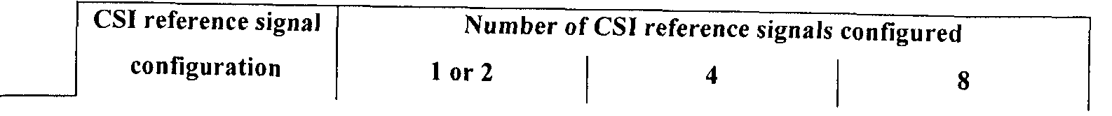
[92] 한편, 상술한 CSI-RS 는 CRS와 별도로 PDSCH에 대한 채널 측정을 목적으로 제안되었으며, CRS와 달리 CSIᅳ RS는 다중 샐 환경에서 셀 간 간섭 (inter-cell interference; ICI)를 줄이기 위하여 최대 32가지의 서로 다른 자원 설정 (configuration)으로 정의될 수 있다. Meanwhile, the above-described CSI-RS has been proposed for channel measurement for PDSCH separately from the CRS. Unlike the CRS, the CSI-RS is used to reduce inter-cell interference (ICI) in a multi-sal environment. Up to 32 different resource configurations can be defined.
[93] CSI-RS (자원) 설정은 안테나 포트 개수에 따라 서로 다르며, 인접 셀 간에는 최대한 다른 (자원) 설정으로 정의되는 CSI-RS가 송신되도록 구성된다. The CSI-RS (resource) configuration is different depending on the number of antenna ports, and configured to transmit CSI-RS defined by a different (resource) configuration as much as possible between adjacent cells.
CSI-RS는 CRS와 달리 최대 8개의 안테나 포트까지 지원하며, 3GPP 표준문서에서는 안테나 포트 15 내지 22까지 총 8개의 안테나 포트를 CSI-RS를 위한 안테나 포트로 할당한다. 아래 표 1 및 표 2는 3GPP 표준문서에서 정의하고 있는 CSI— RS 설정을 나타내며, 특히, 표 1은 일반 (Normal CP)인 경우를, 표 2는 일반 (Extended CP)인 경우를 나타낸다.
[94] 【표 1】 Unlike CRS, CSI-RS supports up to 8 antenna ports, and 3GPP standard documents allocate 8 antenna ports as antenna ports for CSI-RS. Table 1 and Table 2 below show the CSI RS configuration defined in the 3GPP standard document. In particular, Table 1 shows a case of Normal CP, and Table 2 shows a case of Extended CP. [94] [Table 1]
[95] 표 2】 Table 2]
[96] 표 1 및 표 2에서, 는 RE 인덱스를 나타내며, k' 는 부반송파 인덱스를, I'는 0FDM 심볼 인덱스를 나타낸다. 도 11은 현재 3GPP 표준문서에서 정의된 CSI-RS 설정 중 일반 CP인 경우의 CSI-RS 설정 #0을 예시한다. In Table 1 and Table 2, RE represents an RE index, k 'represents a subcarrier index, and I' represents an 0FDM symbol index. FIG. 11 exemplifies CSI-RS configuration # 0 in the case of a general CP among CSI-RS configuration defined in the current 3GPP standard document.
[97] 또한, CSI-RS 서브프레임 설정이 정의될 수 있으며, 이는 서브프레임 단위로 표현되는 주기 ( rcSI-RS )와 서브프레임 오프셋 ( Acs s )으로 구성된다. 아래 표 3은, 3GPP 표준문서에서 정의하고 있는 CSI-RS 서브프레임 설정을 나타낸디-.
[98] 【표 3】 In addition, the CSI-RS subframe configuration may be defined, and is composed of a period ( r c SI - RS ) and a subframe offset (Acs s) expressed in units of subframes. Table 3 below shows CSI-RS subframe configuration defined in 3GPP standard document. [98] [Table 3]
[99] 현재 ZP( zero-power) CSI-RS에 관한 정보는 아래 표 4와 같은 형태로 RRC 계층 신호를 통하여 CSI-RS-Config-rlO 메시지에 포함되어 전송된다. 특히, ZP CSI-RS 자원 설정은 zeroTxPowerSubframeConfig-rlO와 16 비트 사이즈의 비트맵인 zer oTxPower Resour ceConf i gL i s t -r 10≤. 구성된다. 이 증, zeroTxPowerSubframeConf ig-r 10는 표 3에 해당하는 zcsi— RS값을 통해 해당 ZP CSI- RS가 전송되는 주기 및 서브프레임 오프셋을 알려준다. 또한, zeroTxPowerResourceConfigList-rlO은 ZP CSI-RS 설정을 알려주는 정보로서, 상기 비트맵의 각각의 요소는 상기 표 1 또는 상기 표 2에서 CSI-RS를 위한 안테나 포트가 4개인 열 (Column)에 포함된 설정들을 지시한다. 즉, 현재 3GPP 표준문서에 따르면 ZP CSI-RS는' CSI-RS를 위한 안테나 포트가 4개인 경우만으로 정의된다. The information on the current ZP (zero-power) CSI-RS is transmitted as included in the CSI-RS-Config-rlO message through the RRC layer signal as shown in Table 4 below. In particular, the ZP CSI-RS resource configuration includes zeroTxPowerSubframeConfig-rlO and a 16-bit bitmap, zer oTxPower Resour ceConf i gL ist -r 10≤. It is composed. This increase, zeroTxPowerSubframeConf ig-r 10, indicates the period and subframe offset at which the corresponding ZP CSI-RS is transmitted through the z csi—RS values in Table 3. In addition, zeroTxPowerResourceConfigList-rlO is information indicating ZP CSI-RS configuration, and each element of the bitmap is included in a column having four antenna ports for CSI-RS in Table 1 or Table 2. Instruct the settings. That is, according to current 3GPP standard document ZP CSI-RS is defined only when the antenna port for a 'CSI-RS 4 individuals.
[100] 【표 4】 [100] [Table 4]
-- ASNl START ' ; ~ " ' -ASNl START ' ; ~ "'
CSI-RS-Config-rlO ::= SEQUENCE { CSI-RS-Config-rlO :: = SEQUENCE {
csi-RS-rl0 CHOICE { csi-RS-rl0 CHOICE {
zeroTxPowerCSI-RS-rlO CHOICE { zeroTxPowerCSI-RS-rlO CHOICE {
release NULL, release NULL,
setup SEQUENCE { setup SEQUENCE {
zeroTxPo werResourceConfigList-r 10 ΒΓΓ STRING (SIZE (16)), zeroTxPo werResourceConfigList-r 10 ΒΓΓ STRING (SIZE (16)),
zeroTxPowerSubframeConfig-rlO INTEGER (0..154) zeroTxPowerSubframeConfig-rlO INTEGER (0..154)
[101] 참고로, 현재 3GPP 표준문서에 따르면 CQI 인덱스와 이에 대응하는 변조 차수, 코딩 레이트 등은 아래 표 5와 같다. For reference, according to the current 3GPP standard document, the CQI index, corresponding modulation order, coding rate, and the like are shown in Table 5 below.
[102] 【표 5] [102] [Table 5]
[103] 한편, 간섭 측정을 통한 CQI 계산을 위한 동작은 아래와 같다. Meanwhile, an operation for calculating CQI through interference measurement is as follows.
[104] 단말은 CQI 계산 시 필요한 인자로서 SINR을 산출할 필요가 있고, 이 경우 Desired 신호의 수신 전력 측정 (S-measure)을 NZP CSI-RS 등의 RS를 이용하여 수행할 수 있으몌 간섭 전력 측정 (I-measure 혹은 IM( Interference measurement))을 위해 상기 수신한 신호에서 Desired 신호를 제거한 간섭 신호의 전력을 측정한다. The UE needs to calculate the SINR as a necessary factor when calculating the CQI, and in this case, the received power measurement (S-measure) of the Desired signal may be performed by using an RS such as an NZP CSI-RS. For the measurement (I-measure or IM (Interference measurement)), the power of the interference signal obtained by removing the desired signal from the received signal is measured.
[105] CSI 측정을 위한 서브프레임 세트들 Ccsl.0 및 C .1 가 상위 계층 시그널링으로 설정될 수 있으며, 각각의 서브프레임 세트들에 대응하는 서브프레임은 서로 중첩되지 않고 하나의 세트에만 포함된다. 이와 같은 경우,
UE는 S-measure의 경우 특별한 서브프레임 제약 없이 CSI-RS 등의 RS를 통해 수행할 수 있으나, I-measure의 경우 Ccs1'0 및 ^ 1 별로 I-measure를 개별적으로 수행하여 Ccs1.0 및 ^51,1 각각에 대한 두 가지 상이한 CQI계산을 수행하여야 한다. [105] Subframe Sets Ccsl for CSI Measurement. 0 and C. 1 may be set to higher layer signaling, and subframes corresponding to each subframe set are included in only one set without overlapping each other. In this case, The UE may perform the S-measure through RS such as the CSI-RS without special subframe restriction, but in the case of the I-measure, Ccs1 ' 0 and ^ 1 separately perform the I-measure by Ccs1 . Two different CQI calculations should be performed for 0 , ^ 51 , and 1, respectively.
[106] 이하, 하향링크 데이터 채널의 전송 모드에 관하여 예시한다. Hereinafter, a transmission mode of a downlink data channel will be exemplified.
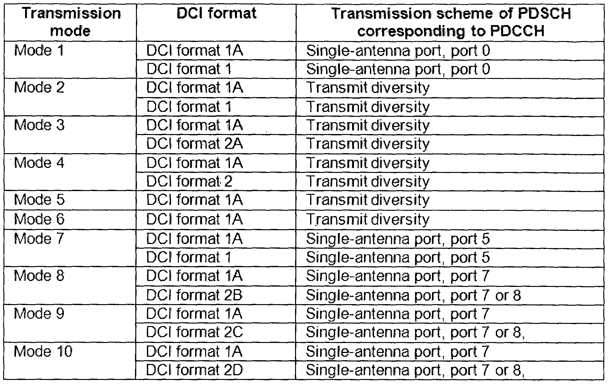
[107] 현재 3GPP LTE 표준문서, 구체적으로 3GPP TS 36.213 문서에서는 아래 표 6 및 표 7와 같이 하향링크 데이터 채널 전송 모드에 관하여 정의하고 있다. 또한, 아래 전송 모드는 상위 계층 시그널링, 즉 RRC 시그널링을 통하여 단말에게 설정된다. The 3GPP LTE standard document, specifically, the 3GPP TS 36.213 document, defines a downlink data channel transmission mode as shown in Tables 6 and 7 below. In addition, the following transmission mode is set to the terminal through higher layer signaling, that is, RRC signaling.
[108] 【표 6】
[108] [Table 6]
[110] 표 6 및 표 7를 참조하면 , 현재 3GPP LTE 표준문서에서는, PDCCH에 마스킹된 R TI의 종류에 따른 하향링크 제어 정보 (Downlink Control Information; DCI) 포맷이 정의되어 있으며, 특히 Cᅳ RNTI와 SPS C-RNTI의 경우, 전송 모드와 이에 대웅하는 DCI 포맷, 즉 전송 모드 기반 DCI 포맷을 도시하고 있다. 또한ᅳ 각각의 전송 모드에 무관하게 적용될 수 있는, 즉 폴백 (Fall-back) 모드를 위한 DCI 포맷 1A가' 정의되어 있다. 상기 표 6은 PDCCH에 마스킹된 RNTI의 종류가 Cᅳ RNTI인 경우를 예시한 것이며 , 상기 표 7는 PDCCH에 마스킹된 RNTI의 종류가 SPS ORNTI인 경우를 예시한 것이다. Referring to Table 6 and Table 7, the current 3GPP LTE standard document, the downlink control information (DCI) format according to the type of R TI masked on the PDCCH is defined, in particular C RNTI In the case of and SPS C-RNTI, a transmission mode and a corresponding DCI format, that is, a transmission mode based DCI format are illustrated. In addition, DCI format 1A 'is defined for fall-back mode that can be applied regardless of each transmission mode. Table 6 illustrates a case where the type of RNTI masked on the PDCCH is C ᅳ RNTI, and Table 7 illustrates a case where the type of the RNTI masked on the PDCCH is SPS ORNTI.
[111] 전송 모드에 관한 동작 예로서, 단말이 표 6에서 C-RNTI로 마스킹된 PDCCH를 블라인드 디코딩한 결과 DCI포맷 1B가 검출된다면, 단일 레이어를 이용한 폐루프 공간 다중화 기법으로 PDSCH가 전송되었다고 가정하여 PDSCH를 디코딩한다. As an operation example of the transmission mode, if the DCI format 1B is detected as a result of the UE blind decoding the PDCCH masked with C-RNTI in Table 6, it is assumed that the PDSCH is transmitted by a closed loop spatial multiplexing technique using a single layer. To decode the PDSCH.
[112] 또한, 상기 표 6 및 표 7 에서 전송 모드 10은 상술한 CoMP 전송 방식의 하향링크 데이터 채널 송신 모드를 의미한다. 표 6을 예를 들어 설명하면, 단말이 C-RNTI로 마스킹된 PDCCH를 블라인드 디코딩한 결과 DCI포맷 2D가 검출된다면 안테나 포트 7 내지 14, 즉 DM-RS에 기반하여 다중 레이어 전송 기법으로 PDSCH가
전송된다는 가정하에 PDSCH를 디코딩한다. 또는 DM-RS 안테나 포트 7 또는 8에 기반하여 단일 안테나 전송 기법으로 PDSCH가 전송된다는 가정하에 PDSCH를 디코딩한다. In addition, the transmission mode 10 in Table 6 and Table 7 refers to the downlink data channel transmission mode of the CoMP transmission scheme described above. Referring to Table 6 as an example, if the DCI format 2D is detected as a result of blind decoding of the PDCCH masked by the C-RNTI, the PDSCH may be transmitted using a multilayer transmission scheme based on antenna ports 7 to 14, that is, DM-RS. The PDSCH is decoded under the assumption that it is transmitted. Alternatively, the PDSCH is decoded on the assumption that the PDSCH is transmitted by a single antenna transmission scheme based on the DM-RS antenna ports 7 or 8.
[113] 반면에, C-RNTI로 마스킹된 PDCCH를 블라인드 디코딩한 결과 DCI포맷 1A가 검출된다면, 해당 서브프레임이 MBSFN 서브프레임인지 여부에 따라 전송 모드가 달라진다. 예를 들어 해당 서브프레임이 비 (非) -MBSFN 서브프레임인 경우 PDSCH는 안테나 포트 0의 CRS에 기반한 단일 안테나 전송 또는 CRS 기반 전송 다이버시티 기법으로 전송되었다는 가정하에 디코딩한다. 또한, 해당 서브프레임이 鹏 SFN 서브프레임인 경우 PDSCH는 안테나 포트 7의 DM-RS에 기반한 단일 안테나 전송이 이루어졌다는 가정하게 디코딩할 수 있다. On the other hand, if the DCI format 1A is detected as a result of blind decoding the PDCCH masked with C-RNTI, the transmission mode varies depending on whether the corresponding subframe is an MBSFN subframe. For example, if the corresponding subframe is a non-MBSFN subframe, the PDSCH is decoded under the assumption that it is transmitted using a single antenna transmission based on CRS of antenna port 0 or a CRS based transmission diversity scheme. In addition, when the corresponding subframe is a 鹏 SFN subframe, the PDSCH may decode assuming that a single antenna transmission based on the DM-RS of the antenna port 7 is performed.
[114] 한편, 최근 3GPP LTE-A 표준에서는, CoMP 방식의 PDSCH 전송인, 전송 모드 10을 위하여, DCI 포맷 2D에 PQI (PDSCH RE Mapping and Quasi-Co-Locat ion Indicator) 필드를 정의하였다. 구체적으로, 상기 PQI 필드는 2 비트 사이즈로 정의되어 총 4개의 스테이트들을 지시하고, 각각의 스테이트에서 지시하는 정보는 CoMP 방식의 PDSCH를 수신하기 위한 파라미터 세트로서 , 구체적인 값들은 상위 계층을 통하여 미리 시그널링된다. ' Meanwhile, in the recent 3GPP LTE-A standard, a PDSCH RE Mapping and Quasi-Co-Locat ion Indicator (PQI) field is defined in DCI format 2D for transmission mode 10, which is a CoMP PDSCH transmission. Specifically, the PQI field is defined in a 2-bit size to indicate a total of four states, and the information indicated in each state is a parameter set for receiving a PDMP of CoMP scheme, and specific values are signaled in advance through an upper layer. do. '
[115] 상기 파라미터 세트에 포함되는 정보는, CRS 안테나 포트의 개수 (crs— PortsCount), CRS의 주파수 천이 값 (crs-FreqShi f t ) , MBSFN 서브프레임 설정 (mbsf n-Subf rameConf igLi st ) , ZP CSI-RS 설정 (csi-RS一 Conf igZPId) , PDSCH 시작 심볼 (pdsch-Start), NZP (Non-ZP) CSI— RS의 QCL (Quasi Co-Location)정보 (qc — CSI-RS-ConfigNZPId) 정보 중 하나 이상이 포함된다. The information included in the parameter set includes the number of CRS antenna ports (crs—PortsCount), the frequency shift value of the CRS (crs-FreqShi ft), the MBSFN subframe configuration (mbsf n-Subf rameConf igLi st), and ZP. CSI-RS configuration (csi-RS 一 Conf igZPId), PDSCH start symbol (pdsch-Start), NZP (Non-ZP) CSI—Quasi Co-Location (QCL) information of RS (qc — CSI-RS-ConfigNZPId) One or more of them are included.
[116] 이하, QCL (Quasi C으 Locat ion)에 관하여 설명한다. Hereinafter, QCL (Quasi C Locat ion) will be described.
[117] 안테나 포트 간에 QCL되어 있다는 것은, 단말이 하나의 안테나 포트로부터 수신하는 신호 (흑은 해당 안테나 포트에 대웅하는 무선 채널)의 광범위 특성들 (large-scale properties)이 다른 하나의 안테나 포트로부터 수신하는 신호 (흑은 해당 안테나 포트에 대웅하는 무선 채널)의 광범위 특성들과 모두 또는 일부가 동일하다고 가정할 수 있다는 것을 의미한다. 여기서, 상기 광범위 특성들은 주파수 오프셋과 관련된 도플러 확산 (Doppler spread) , 도플러 시프트
(Doppler shift), 타이밍 오프셋과 관련된 평균 지연 (average delay), 지연 확산 (delay spread) 등을 포함하고, 나아가 평균 이득 (average gain) 또한 포함할 수 있다. QCL between antenna ports means that the large-scale properties of a signal received by a terminal from one antenna port (black is a wireless channel to the corresponding antenna port) are different from one antenna port. This means that you can assume that all or some of the broad characteristics of the signal you are receiving (black is the radio channel to the corresponding antenna port) are the same. Here, the broad characteristics are Doppler spread, Doppler shift related to frequency offset. (Doppler shift), average delay associated with timing offset, delay spread, and the like, and may also include average gain.
[118] 위 정의에 의하면, 단말은 QCL되지 않은 안테나 포트, 즉 NQCUNon Quasi co-Located)된 안테나 포트들 간에는 광범위 특성들이 동일하다고 가정할 수 없다. 이 경우 단말은 안테나 포트 별로 주파수 오프셋 및 타이밍 오프셋 등을 획득하기 위한 트택킹 (tracking) 절차를 독립적으로 수행하여야 한다. According to the above definition, the UE cannot assume that the wide range characteristics are the same among non-QCL antenna ports, that is, NQCUNon Quasi co-Located antenna ports. In this case, the UE must independently perform a tracking procedure for acquiring a frequency offset and a timing offset for each antenna port.
[119] 반면에, QCL되어 있는 안테나 포트들 간에는 단말이 아래와 같은 동작을 수행할 수 있다는 장점이 있다. On the other hand, there is an advantage that the UE may perform the following operations between the QCL antenna ports.
[120] 1) 단말이 특정 안테나 포트에 대웅하는 무선 채널에 대한 전력 -지연 프로파일 (power-delay profile), 지연 확산 및 도플러 스펙트럼 (Doppler spectrum)와 도플러 확산 추정 결과를, 다른 안테나 포트에 대응하는 무선 채널에 대한 채널 추정 시 사용되는 위너 필터 (Wiener filter) 파라미터 등에 동일하게 적용할 수 있다. 1) The terminal corresponds to a power-delay profile, delay spread, Doppler spectrum, and Doppler spread estimation results for a wireless channel that the terminal corresponds to a different antenna port. The same applies to Wiener filter parameters used for channel estimation for a wireless channel.
[121] 2) 또한, 단말은 상기 특정 안테나 포트에 대한 시간 동기 및 주파수 동기를 획득한 후, 동일한 동기를 다른 안테나 포트에 대하여도 적용할 수 있다. 2) In addition, after acquiring the time synchronization and the frequency synchronization for the specific antenna port, the terminal may apply the same synchronization to other antenna ports.
[122] 3) 마지막으로, 평균 이득에 관하여도 단말은 QCL되어 있는 안테나 포트들 각각에 대한 RSRP (Reference Signal Received Power) 측정값올 평균치로 계산할 수 있다. 3) Finally, regarding the average gain, the UE may calculate a reference signal received power (RSRP) measurement value for each of the QCL antenna ports.
[123] 예를 들어, 단말이 PDCCH (혹은 EPDCCH)를 통해 DM— RS 기반 하향링크 데이터 채널 스케줄링 정보, 예를 들어, DCI 포맷 2D를 수신하면, 단말은 상기 스케줄링 정보에서 지시하는 DM-RS 시퀀스를 통하여 PDSCH에 대한 채널 추정을 수행한 후, 데이터 복조를 수행하는 경우로 가정한다. For example, when the terminal receives DM—RS based downlink data channel scheduling information, for example, DCI format 2D through a PDCCH (or EPDCCH), the terminal indicates a DM-RS sequence indicated by the scheduling information. It is assumed that data demodulation is performed after performing channel estimation on the PDSCH through.
[124] 이와 같은 경우, 단말이 하향링크 데이터 채널 복조를 위한 DM-RS 안테나 포트가 서빙 셀의 CRS 안테나 포트와 QCL되어 있다면, 단말은 해당 DM-RS 안테나 포트를 통한 채널 추정 시 자신의 CRS 안테나 포트로부터 추정했던 무선 채널의 광범위 특성들 (large-scale properties)을 그대로 적용하여 DM-RS 기반 하향링크 데이터 채널 수신 성능을 향상시킬 수가 있다.
[125] 마찬가지로, 단말이 하향링크 데이터 채널 복조를 위한 DM-RS 안테나 포트가 서빙 셀의 CSI-RS 안테나 포트와 QCL되어 있다면, 단말은 해당 DM— RS 안테나 포트를 통한 채널 추정 시 서빙 셀의 CSIᅳ RS 안테나 포트로부터 추정했던 무선 채널의 광범위 특성들 (largeᅳ scale properties)을 그대로 적용하여 DM-RS 기반 하향링크 데이터 채널 수신 성능을 향상시킬 수가 있다. In this case, if the UE is QCLed with the CRS antenna port of the serving cell for the DM-RS antenna port for downlink data channel demodulation, the UE estimates its CRS antenna when channel estimation is performed through the corresponding DM-RS antenna port. DM-RS-based downlink data channel reception performance can be improved by applying large-scale properties of the radio channel estimated from the port. Similarly, if the UE is QCLed with the CSI-RS antenna port of the serving cell for the DM-RS antenna port for downlink data channel demodulation, the UE performs CSI of the serving cell when channel estimation is performed through the corresponding DM—RS antenna port. DM DM-RS-based downlink data channel reception performance can be improved by applying the large scale properties of the radio channel estimated from the RS antenna port.
[126] 한편, LTE 시스템에서는 CoMP 모드인 전송 모드 10으로 하향링크 신호를 송신할 시 , 기지국이 상위 계층 신호를 통하여 QCL 타입 A와 QCL 타입 B 중 하나를 단말에게 설정하도록 정의하고 있다. Meanwhile, in the LTE system, when transmitting a downlink signal in transmission mode 10 of CoMP mode, the base station defines one of the QCL type A and the QCL type B to the UE through an upper layer signal.
[127] 여기서, QCL 타입 A는 CRS 및 CS1-RS및 DM— RS의 안테나 포트가 평균 이득을 제외한 나머지 광범위 특성들이 QCL되어 있다고 가정하는 것으로, 동일 노드 (point)에서 물리 채널 및 신호들이 전송되고 있음을 의미한다. [127] Here, QCL type A assumes that the antenna ports of CRS, CS1-RS, and DM—RS have QCLs except for the average gain, and that the wide range characteristics are QCLed, and physical channels and signals are transmitted at the same node. It means that there is.
[128] 반면에, QCL 타입 B는 DM-RS 및 특정 지시된 CSI-RS의 안테나 포트가 평균 이득을 제외한 나머지 광범위 특성들이 QCL되어 있다고 가정하는 것아다. 특히, QCL 타입 B는 DPS, JT등의 CoMP전송이 가능하도록 단말당 최대 4개까지의 QCL 모드를 상위 계층 메시지를 통해 설정하고, 이 중 어떤 QCL 모드로 하향링크 신호를 수신해야 하는지 동적으로 DCI (downlink control informat ion)를 통해 설정하도록 정의되어 있다. 이러한 정보는 상기 PQI 필드의 파라미터 세트 중 qcl一 CSI-RS-ConfigNZPId에 정의된다. [128] On the other hand, QCL type B does not assume that the antenna ports of the DM-RS and the specific indicated CSI-RS are QCL except for the average gain. In particular, QCL type B sets up to four QCL modes per UE through upper layer messages to enable CoMP transmission of DPS, JT, etc., and which of these QCL modes should dynamically receive downlink signals in DCI. defined via downlink control informat ion. This information is defined in qcl I CSI-RS-ConfigNZPId of the parameter set of the PQI field.
[129] QCL 타입 B가 설정된 경우의 DPS 전송에 관하여, 보다 구체적으로 설명한다. DPS transmission when the QCL type B is set will be described in more detail.
[130] 우선, 개의 안테나 포트들로 구성된 노드 #1는 CSI-RS 자원 (resource) #1를 전송하고, N2개의 안테나 포트들로 구성된 노드 #2는 CSI-RS 자원 (resource) #2를 전송하는 것으로 가정한다. 이 경우, CSI-RS 자원 #1을 상기 PQI의 파라미터 세트 #1에 포함시키고, CSI-RS 자원 #2를 상기 PQI의 파라미터 세트 #2에 포함시킨다. 나아가, 기지국은 노드 #1과 노드 #2의 공통 커버리지 내에 존재하는 단말에게 상위 계층을 통하여 파라미터 세트 #1과 파라미터 세트 #2를 시그널링한다. [130] First, node # 1 consisting of two antenna ports transmits CSI-RS resource # 1, and node # 2 consisting of N 2 antenna ports receives CSI-RS resource # 2. Assume to transmit. In this case, CSI-RS resource # 1 is included in parameter set # 1 of the PQI and CSI-RS resource # 2 is included in parameter set # 2 of the PQI. Furthermore, the base station signals the parameter set # 1 and the parameter set # 2 to the terminal existing within the common coverage of the node # 1 and the node # 2 through the upper layer.
[131] 이후, 기지국이 해당 단말에게 노드 #1을 통해 데이터 (즉, PDSCH) 전송 시 DCI를 이용하여 파라미터 세트 #1을 설정하고, 노드 #2를 통해 데이터 전송시
파라미터 세트 #2를 설정하는 방식으로 DPS를 수행할 수 있다. 단말 입장에서는 DCI를 통해 상기 PQI를 통하여 파라미터 세트 #1을 설정 받으면 CSI-RS 자원 #1과 DM-RS가 QCL되어 있다고 가정하고, 상기 PQI를 통하여 파라미터 세트 #2를 설정 받으면 CSI-RS 자원 #2과 DM-RS가 QCL되어 있다고 가정할 수 있다. Afterwards, the base station sets parameter set # 1 using DCI when transmitting data (that is, PDSCH) to the corresponding terminal through node # 1, and transmits data through node # 2. DPS may be performed by setting parameter set # 2. The UE assumes that the CSI-RS resource # 1 and the DM-RS are QCLed when the parameter set # 1 is set through the PQI through the DCI, and the CSI-RS resource # is set when the parameter set # 2 is set through the PQI. It can be assumed that 2 and DM-RS are QCLed.
[132] 한편, 현재의 무선통신환경은 M2M(Machine-to-Machine) 통신 및 높은 데이터 전송량을 요구하는 다양한 디바이스의 출현 및 보급으로 셀를러 망에 대한 데이터 요구량이 매우 빠르게 증가하고 있다. 높은 데이터 요구량을 만족시키기 위해 통신 기술은 더 많은 주파수 대역을 효율적으로 사용하기 위한 반송파 집성 (carrier aggregation) 기술 등과 한정된 주파수 내에서 데이터 용량을 높이기 위해 다중 안테나 기술, 다중 기지국 협력 기술 등으로 발전하고 있고, 통신 환경은 사용자 주변에 액세스 할 수 있는 노드의 밀도가, 높아지는 방향으로 진화한다. 이러한 높은 밀도의 노드를 갖춘 시스템은 노들 간의 협력에 의해 더 높은 시스템 성능을 보일 수 있다. 이러한 방식은 각 노드가 독립적인 기지국 (Base Station (BS) , Advanced BS (ABS) , Node-B (NB) , eNode-B (eNB) , Access Point (AP) 등)으로 동작하여 서로 협력하지 않을 때보다 훨씬 우수한 성능을 갖는다. On the other hand, the current wireless communication environment is rapidly increasing the data requirements for the cell network due to the emergence and spread of various devices requiring machine-to-machine communication and high data transmission. To meet high data demands, communication technologies are evolving into multi-antenna technology, multi-base station cooperative technology, etc. to increase data capacity within a limited frequency, such as carrier aggregation technology to efficiently use more frequency bands. , The communication environment evolves in the direction of increasing the density of nodes that can be accessed around the user. Systems with such high density nodes can exhibit higher system performance by cooperation between furnaces. In this way, each node operates as an independent base station (Base Station (BS), Advanced BS (ABS), Node-B (NB), eNode-B (eNB), Access Point (AP), etc.) It has much better performance than ever.
[133] 도 12는 차세대 통신 시스템에서 다중 노드 시스템을 예시하는 도면이다. 12 is a diagram illustrating a multi-node system in a next generation communication system.
[134] 도 12를 참조하면, 모든 노드가 하나의 컨트롤러에 의해 송수신을 관리 받아 개별 노드가 하나의 셀의 일부 안테나 집단처럼 동작을 한다면, 이 시스템은 하나의 샐을 형성하는 분산 다중 노드 시스템 (distributed multi node system; DMNS)으로 볼 수 있다. 이 때 개별 노드들은 별도의 Node ID를 부여 받을 수도 있고, 별도의 Node ID없이 셀 내의 일부 안테나처럼 동작할 수도 있다. 그러나, 노드들이 서로 다른 셀 식별자 (Cell identifier; ID)를 갖는다면 이는 다중 셀 시스템으로 볼 수 있다. 이러한 다중 셀이 커버리지에 따라 중첩 형태로 구성된다면 이를 다중 티어 네트워크 (multi— tier network)라고 부른다. Referring to FIG. 12, if all nodes are managed by a controller and each node operates as a group of antennas of one cell, the system may be a distributed multi-node system that forms one cell. It can be seen as a distributed multi node system (DMNS). In this case, individual nodes may be given a separate Node ID, or may operate like some antennas in a cell without a separate Node ID. However, if the nodes have different cell identifiers (IDs), this can be viewed as a multi-cell system. If these multiple cells are configured in overlapping form according to their coverage, this is called a multi-tier network.
[135] 한편 , Node-B, eNode-B, PeNB) , HeNB, 腿 (Remote Radio Head) , 릴레이 및 분산 안테나 등이 노드가 될 수 있으며 하나의 노드에는 최소 하나의 안테나가 설치된다. 노드는 전송 포인트 (Transmission Point)라 불리기도 한다. 노드 (node)는 통상 일정 간격이상으로 떨어진 안테나 그룹을 일컫지만, 본
발명에서는 노드를 간격에 상관없이 임의의 안테나 그룹으로 정의하더라도 적용할 수 있다. On the other hand, Node-B, eNode-B, PeNB), HeNB, 릴레이 (Remote Radio Head), relay and distributed antenna can be a node, at least one antenna is installed in one node. Nodes are also called transmission points. A node usually refers to a group of antennas separated by more than a certain distance. In the present invention, even if the node is defined as an arbitrary antenna group regardless of the interval, it can be applied.
[136] 상술한 다중 노드 시스템 및 릴레이 노드의 도입으로 인하여, 다양한 통신 기법의 적용이 가능해져 채널 품질 개선이 이루어질 수 있지만, 앞서 언급한 MIM0 기법 및 셀 간 협력 통신 기법을 다중 노드 환경에 적용하기 위해서는 새로운 제어 채널의 도입이 요구되고 있다. 이러한 필요로 인해 새롭게 도입이 거론되고 있는 제어 채널이 EPDCCH( Enhanced PDCCH) 이며, 기존의 제어 영역 (이하, PDCCH 영역)이 아닌 데이터 영역 (이하 PDSCH 영역으로 기술)에 할당하는 것으로 결정되었다. 결론적으로, 이러한 EPDCCH를 통해 각 단말 별로 노드에 대한 제어 정보를 전송이 가능해져 기존의 PDCCH 영역이 부족할 수 있는 문제 역시 해결할 수 있다. 참고로, EPDCCH는 기존의 레거시 단말에게는 제공되지 않고, LTE-A 단말만이. 수신할 수 있다. 또한, EPDCCH는 기존 셀 특정 참조 신호인 CRS가 아니라, DM-RS (혹은 CSI- RS)에 기반하여 전송 및 수신이 이루어진다. Due to the introduction of the multi-node system and the relay node described above, various communication techniques can be applied to improve channel quality, but the aforementioned MIM0 technique and inter-cell cooperative communication technique can be applied to a multi-node environment. The introduction of a new control channel is required. Due to this need, the newly introduced control channel is EPDCCH (Enhanced PDCCH), and it has been decided to allocate it to a data region (hereinafter referred to as PDSCH region) instead of an existing control region (hereinafter PDCCH region). In conclusion, it is possible to transmit the control information for the node for each terminal through the EPDCCH can also solve the problem that the existing PDCCH region may be insufficient. For reference, the EPDCCH is not provided to the legacy legacy terminal, only the LTE-A terminal . Can be received. In addition, EPDCCH is transmitted and received based on DM-RS (or CSI-RS), not CRS, which is an existing cell specific reference signal.
[137] 도 13은 EPDCCH와 EPDCCH에 의하여 스케줄링되는 PDSCH를 예시하는 도면이다. FIG. 13 is a diagram illustrating an EPDCCH and a PDSCH scheduled by an EPDCCH.
[138] 도 13을 참조하면, PDCCH 1 및 PDCCH 2는 각각 PDSCH 1 및 PDSCH 2를 스케즐링하고, EPDCCH는 다른 PDSCH를 스케줄링하늪 것을 알 수 있다. 특히, 도 13에서는 EPDCCH가 서브프레임의 4 번째 심볼부터 시작하여 마지막 심볼까지 전송됨을 도시한다. EPDCCH는 일반적으로 데이터를 전송하는 PDSCH 영역을 통해서 전송될 수 있으며, 단말은 자신의 EPDCCH 유무를 검출하기 위하여, EPDCCH 후보를 모니터링한다. 13, it can be seen that PDCCH 1 and PDCCH 2 schedule PDSCH 1 and PDSCH 2, respectively, and EPDCCH schedules another PDSCH. In particular, FIG. 13 shows that the EPDCCH is transmitted from the fourth symbol of the subframe to the last symbol. In general, the EPDCCH may be transmitted through a PDSCH region for transmitting data, and the UE monitors an EPDCCH candidate to detect the presence or absence of its own EPDCCH.
[139] 이하, 반—정적 스케줄링 (Semi-persistent scheduling) 기법에 관하여 설명한다. [139] Hereinafter, a semi-persistent scheduling technique will be described.
[140] 현재 LTE시스템에서 SPS( semi -per si stent scheduling)는 RRC 시그널링으로 어느 서브프레임들에서 (구체적으로, 서브프레임 주기와 오프셋으로) SPS PDSCH 송수신을 수행하여야 하는지를 UE에게 미리 알려주고, 실제 SPS의 활성화 및 해제는 PDCCH를 통해서 수행한다. In the current LTE system, semi-per si stent scheduling (SPS) informs the UE in advance of which subframes (specifically, with subframe periods and offsets) to perform transmission and reception in RRC signaling to the UE in advance. Activation and release of is performed through the PDCCH.
[141] 즉, UE는 RRC 시그널링을 통하여 SPS 정보를 할당 받더라도 바로 SPS 송수신를 수행하는 게 아니라 활성화 (또는 재활성화)을 알리는 PDCCH를 수신
(구체적으로, SPS C-RNTI로 마스킹된 PDCCH를 검출)하면 그 PDCCH에서 지정한 자원 할당 정보 등을 이용하여, 상기 SPS 정보에서 지정한 서브프레임 주기와 오프셋으로 SPS 송수신을 수행하며, SPS 해제를 지시하는 PDCCH를 수신하면 SPS 송수신을 중단한다. In other words, even if the UE receives SPS information through RRC signaling, the UE does not immediately perform transmission / reception of the SPS but receives a PDCCH indicating activation (or reactivation). (Specifically, if the PDCCH masked by the SPS C-RNTI is detected), the SPS is transmitted and received at the subframe period and offset specified in the SPS information using the resource allocation information specified in the PDCCH and instructs to release the SPS. When receiving the PDCCH, the transmission and reception of the SPS is stopped.
[142] 이와 같이 중단된 SPS 송수신은 활성화 (또는 재활성화)을 알리는 PDCCH를 수신하면, 다시 그 PDCCH에서 지정한 자원 할당 정보 등을 이용하여, 상기 SPS 정보에서 지정한 서브프레임 주기와 오프셋으로 SPS송수신을 재개한다. When the suspended SPS transmission / reception receives a PDCCH indicating activation (or reactivation), the SPS transmission / reception is performed at a subframe period and offset specified in the SPS information by using resource allocation information specified in the PDCCH. Resume.
[143] <제 1실시예 > [First Embodiment]
[144] 만일, UE가 상기 QCL 타입 A로 설정된 경우, 특정 PQI 스테이트가 지시하는 CRS 관련 정보, 보다 구체적으로 CRS RE로 인한 RM rate matching) 수행 정보가' 비 (None)-서빙 셀의 정보인 경우가 발생할 수 있다. 이 때 서빙 샐은 non— MBSFN 서브프레임이지만 상기 PQI로부터 지시된 MBSFN 서브프레임정보에 의하면 현재 서브프레임이 MBSFN 서브프레임올 지시하고 있는 경우와 같은 경우라면, 지시된 CRS M정보에 의해서 RM을 수행할 경우, 서빙 셀의 CRS RE가 RM되지 않아 PDSCH RE와 겹치는 문제가 발생할 수 있다. If the UE is set to the QCL type A, CRS related information indicated by a specific PQI state, more specifically, RM rate matching performance information due to a CRS RE is ' None-serving cell information' Cases may occur. At this time, the serving cell is a non—MBSFN subframe, but according to the MBSFN subframe information indicated by the PQI, if the current subframe indicates the MBSFN subframe, the RM is performed by the indicated CRS M information. In this case, since the CRS RE of the serving cell is not RM, a problem of overlapping with the PDSCH RE may occur.
[145] 즉, PDSCH의 특정 RE들이 서빙 셀의 CRS와 겹친다는 의미는, QCL 타입 A의 경우 PDSCH는 서빙 셀이 전송하고 있으므로 서빙 셀이 해당 RE에서 CRS와 PDSCH를 동시에 전송해야 하고 UE는 이를 수신하게 되는 경우가 발생한다는 의미한다. 이 경우 해당 PDSCH RE는 CRS에 의해 심각한 간섭을 받게 된다. That is, the specific REs of the PDSCH overlap with the CRS of the serving cell. In the case of the QCL type A, since the PDSCH is transmitted by the serving cell, the serving cell must simultaneously transmit the CRS and the PDSCH in the corresponding RE. It means that the reception occurs. In this case, the PDSCH RE is severely interfered by the CRS.
[146] 이러한 문제점은 PDSCH가 아닌 EPDCCH에 대해서도 발생할 수 있다. 즉, EPDCCH가 QCL 타입 A로 설정된 경우 특정 PQI를 따르도록 설정될 수 있고, 상기 특정 PQI로부터 지시되는 CRS RM정보가 비―서빙 셀의 정보가 지시될 수 있다. 이 때 서빙 셀 CRS와 EPDCCH사이에 특정 RE에서 층돌이 발생할 수 있다. This problem may occur for EPDCCH other than PDSCH. That is, when the EPDCCH is set to the QCL type A, it may be configured to follow a specific PQI, and CRS RM information indicated by the specific PQI may indicate information of a non-serving cell. At this time, delamination may occur in a specific RE between the serving cell CRS and the EPDCCH.
[147] 이러한 경우에 대하여 다음과 같은 해결책이 가능하다. [147] In this case, the following solution is possible.
[148] 1) 우선, UE는 서빙 샐 CRS와 PDSCH (또는 EPDCCH) RE가 충돌이 되도록 스케줄링 받올 것을 기대하지 않는 것으로 규정할 수 있다. 만일 지시된 CRS RM관련 정보가 비 -서빙 셀의 정보인 경우, 예를 들어 현재 서브프레임이 서빙 셀이 non-MBSFN이고 상기 지시된 CRS RM관련 MBSFN SF정보가 MBSFN인 경우 스케줄링
받지 않을 것이라고 가정할 수 있다. eNB는 PDSCH (또는 EPDCCH)가 QCL 타입 A로 설정된 경우, 서빙 샐이 non-MBSFN 서브프레임이라면 비 -서빙 샐의 CRS RM 정보를 지시하는 PQI를 이용하여 PDSCH (또는 EPDCCH)를 전송할 수가 없다는 것을 의미하며, 비 -서빙 셀의 CRS RM 정보를 지시하는 PQI는 오직 서빙 샐이 MBSFN 서브프레임일 때만 사용 가능하다는 것을 의미한다 . [148] 1) First, the UE may define that the serving cell CRS and the PDSCH (or EPDCCH) RE do not expect to be scheduled to collide. If the indicated CRS RM related information is information of a non-serving cell, for example, if the current subframe is a serving cell non-MBSFN and the indicated CRS RM related MBSFN SF information is MBSFN scheduling It can be assumed that it will not be received. If the PDSCH (or EPDCCH) is set to QCL type A, the eNB means that the PDSCH (or EPDCCH) cannot be transmitted using the PQI indicating the CRS RM information of the non-serving cell if the serving cell is a non-MBSFN subframe. The PQI indicating the CRS RM information of the non-serving cell means that the serving cell can be used only when the serving cell is an MBSFN subframe.
[149] 2) 또는, UE는 서빙 셀 CRS와 PDSCH (또는 EPDCCH)가 특정 RE에서 층돌이 발생하는 경우 해당 RE위치들에 있어서 펑처링 (puncturing)을 적용하는 것이다. 즉, PDSCH (또는 EPDCCH) 수신함에 있어 층돌되는 RE들은 펑처링시켜 제외하고 디코딩을 수행할 수 있다. 이로 인하여, 기지국은 단말의 펑처링 동작을 인지할 수 있으므로, MCS 설정 시 고려할 수 있다. 2) Or, the UE applies puncturing in the corresponding RE positions when serving cells CRS and PDSCH (or EPDCCH) generate stratification at a specific RE. That is, REs stratified in PDSCH (or EPDCCH) reception may be decoded by puncturing. Thus, the base station can recognize the puncturing operation of the terminal, it can be considered when setting the MCS.
[150] 3) 추가적으로, 서빙 셀 CRS와 PDSCH (또는 EPDCCH)가 특정 RE에서 충돌이 발생하는 경우, 기지국도 해당 RE들을 RM(rate matching)하여 PDSCH (또는 EPDCCH)를 전송하되 , UE 역시 해당 RE위치들에 있어서 RM을 추가적으로 수행하는 것으로 정의될 수도 있다. 3) In addition, when a collision occurs between a serving cell CRS and a PDSCH (or EPDCCH) in a specific RE, the base station also transmits the PDSCH (or EPDCCH) by RM matching the corresponding REs, but the UE also corresponds to the RE. It may be defined as additionally performing RM in locations.
[151] 구체적으로, UE가 QCL 타입 A로 설정된 경우 기본적으로 서빙 셀 CRS RE위치들에 있어서는 RM 을 항상 수행하는 것으로 정의될 수 있다. 물론, 기지국도 서빙 셀 CRS RE위치들에는 RM을 적용한다. 즉, PQI등에 의해 지시되는 CRS RM정보가 있을 경우 기지국과 UE는 다중 RM을 수행하는 것으로 볼 수도 있다. In more detail, when the UE is set to QCL type A, it may basically be defined to always perform RM in serving cell CRS RE locations. Of course, the base station also applies RMs to the serving cell CRS RE locations. That is, when there is CRS RM information indicated by PQI, etc., the base station and the UE may be regarded as performing multi-RM.
[152] 상기 PQI 필드에서 지시하는 파라미터 세트는 아래 표 8과 같이 정의될 수 있다. A parameter set indicated by the PQI field may be defined as shown in Table 8 below.
[153] 【표 8】 [153] [Table 8]
PDSCH-RE-MappingQCL-Config-rl 1 ::= SEQUENCE { PDSCH-RE-MappingQCL-Config-rl 1 :: = SEQUENCE {
pdsch-RE-MappingQCL-Configld-rl 1 PDSGH-RE-MappingQCL-Configld-rl 1 , pdsch-RE-MappingQCL-Configld-rl 1 PDSGH-RE-MappingQCL-Configld-rl 1,
pdsch-Start-rl 1 ENUMERATED {reserved, nl, n2, n3, n4, assigned} pdsch-Start-rl 1 ENUMERATED {reserved, nl, n2, n3, n4, assigned}
csi-RS-IdentityZP-rll CSI-RS-WentityZP-rll, csi-RS-IdentityZP-rll CSI-RS-WentityZP-rll,
re-MappingQCL-CSI- S-IdentityNZP-rll CSI-RS-IdentityNZP-rl 1 re-MappingQCL-CSI- S-IdentityNZP-rll CSI-RS-IdentityNZP-rl 1
} }
[154] 상기 표 8에서, pdsch-RE-MappingQCL-Configld-rll는 1~4까지의 값을 갖는 것으로 최대 4개까지의 PQI 스테이트가 존재한다고 가정한다. In Table 8, it is assumed that pdsch-RE-MappingQCL-Configld-rll has a value from 1 to 4, and there are up to 4 PQI states.
[155] 각 PQI 스테이트 별로 PDSCH 시작 심볼 정보 (pdsch-Start-rll), 하나의 ZP CSI-RS 정보 (csi-RS-IdentityZP-rll), QCL및 CRS RM관련 정보 (reᅳ MappingQCL-CSI-
RS-IdentityNZP-rll)가 설정될 수 있다. [155] PDSCH start symbol information (pdsch-Start-rll), one ZP CSI-RS information (csi-RS-IdentityZP-rll), QCL, and CRS RM-related information (re P MappingQCL-CSI-) for each PQI state RS-IdentityNZP-rll) may be set.
[156] 이 때 QCL및 CRS 1 관¾ 정보는, 하나의 특정 NZP CSI-RS 자원 (CSI-RS- IdentityNZP— rll)를 지시하고, QCL 타입 B일 때는 특정 NZP CSI-RS가 DM-RS와 CSI- RS 간 QCL로서 유효하다. At this time, the QCL and CRS 1 management information indicates one specific NZP CSI-RS resource (CSI-RS-IdentityNZP—llll), and when the QCL type B, the specific NZP CSI-RS is associated with the DM-RS. Valid as QCL between CSI and RS.
[157] 추가적으로 상기 특정 NZP CSI-RS는 RRC 계층 시그널링을 통하여 소정의 NZP CSI-RS 자원과 링크될 수 있다. 여기서, NZP CSI-RS에 대한 자원은 아래 표 9와 같이 정의되며, QCL 적용되는 CRS에 관한 정보가 포함된 것을 알 수 있다. 따라서, 본 발명에서는, 링크된 NZP CSI-RS 과 QCL 가정되는 CRS와 상기 특정 NZP CSI- RS간에도 QCL이 적용됨과 동시에, 링크된 NZP CSI-RS 와 QCL 가정되는 CRS의 정보가 해당 PQI 스테이트의 CRS RM정보로도 사용될 수 있도록 디자인 될 수 있다. In addition, the specific NZP CSI-RS may be linked with a predetermined NZP CSI-RS resource through RRC layer signaling. Here, resources for the NZP CSI-RS are defined as shown in Table 9 below, and it can be seen that information on the CRS to which the QCL is applied is included. Therefore, in the present invention, QCL is applied between the linked NZP CSI-RS and QCL hypothesized CRS and the specific NZP CSI-RS, and the information of the linked NZP CSI-RS and QCL hypothesized CRS is the CRS of the corresponding PQI state. It can be designed to be used as RM information.
[158] 【표 9] [158] [Table 9]
CSI- S-ConfigNZP-rll:: = SEQUENCE { CSI- S-ConfigNZP-rll :: = SEQUENCE {
csi-RS-ldentityNZP-rl I CSI-RS-IdentitNZP-rl 1, csi-RS-ldentityNZP-rl I CSI-RS-IdentitNZP-rl 1 ,
antennaPortsCount-rll ENUMERATED (anl, an2, an4, anS>, antennaPortsCount-rll ENUMERATED (anl, an2, an4, anS>,
resourceConfig-rl 1 INTEGER (0..31X resourceConfig-rl 1 INTEGER (0..31X
subframeConfig-rll INTEGER (0..154), subframeConfig-rll INTEGER (0..154),
scramblingldentity-rl 1 INTEGER (0..503), scramblingldentity-rl 1 INTEGER (0..503),
qcl-CRS-Info-rl I SEQUENCE { qcl-CRS-Info-rl I SEQUENCE {
qcl-ScramblingWentit -r iNTEGER (0..503} qcl-ScramblingWentit -r iNTEGER (0..503}
crs-PortsCount-rl I ENUMERATED {nl, n2, n4, spare I }, crs-PortsCount-rl I ENUMERATED {nl, n2, n4, spare I},
mbsfn-SubframeConfig-rl 1 MBSFN-SubframeConfig OPTIONAL, - Need OR mbsfn-SubframeConfig-rl 1 MBSFN-SubframeConfig OPTIONAL,-Need OR
OPTIONAL, -- Need OR OPTIONAL,-Need OR
} }
[159] 만일 QCL 타입 A인 경우, PQI 스테이트에 상기 하나의 NZP CSI-RS 자원 자체는 DM-RS와 CSI-RS 간의 QCL정보로는 적용하지 않도록 하고, 즉 무시하고, 여기에 링크된 NZP CSI-RS 과 QCL 가정되는 CRS에 관한 정보를 통해 이러한 CRS 정보가 해당 PQI 스테이트의 CRS RM정보로도 사용되도록 할 수 있다. In the case of the QCL type A, the one NZP CSI-RS resource itself is not applied to the PQI state as QCL information between the DM-RS and the CSI-RS, that is, ignored and the NZP CSI linked thereto. -RS and QCL The information about the assumed CRS allows this CRS information to be used as the CRS RM information of the corresponding PQI state.
[160] 만일, PDSCH QCL 타입 A이고 EPDCCH QCL 타입 B로 설정된 경우는, PDSCH관련해서는 지시된 NZP CSI-RS 자원은 DM-RS와 CSI-RS 간의 QCL정보로는 적용하지 않도록 하지만, EPDCCH QCL 타입 B를 위해 이 PQI 스테이트가 해당 EPDCCH에 연결되어 있는 경우에는 해당 NZP CSI-RS자원은 EPDCCH 복호를 위한 DM- RS와 CSI-RS 간의 QCL정보로서 의미가 있는 것으로 정의할 수 있다.
[161] 반대로 PDSCH QCL 타입 B이고 EPDCCH QCL 타입 A로 설정된 경우, PDSCH관련해서는 지시된 NZP CSI-RS 자원은 DM-RS와 CSI-RS 간의 QCL정보로서 유효하지만, EPDCCH QCL 타입 A를 위해 이 PQI 스테이트가 해당 EPDCCH에 연결되어 있는 경우에는 해당 NZP CSI-RS 자원 정보는 EPDCCH 복호를 위한 DM-RS와 CSI-RS 간의 QCL정보로서는 무시하는 것으로 정의될 수 있다. If the PDSCH QCL type A is set to the EPDCCH QCL type B, the NZP CSI-RS resource indicated in relation to the PDSCH is not applied as QCL information between the DM-RS and the CSI-RS. When this PQI state is connected to the EPDCCH for B, the NZP CSI-RS resource may be defined as meaningful as QCL information between DM-RS and CSI-RS for EPDCCH decoding. On the contrary, if PDSCH QCL type B is set to EPDCCH QCL type A, the NZP CSI-RS resource indicated in relation to PDSCH is valid as QCL information between DM-RS and CSI-RS, but this PQI is for EPDCCH QCL type A. When the state is connected to the EPDCCH, the corresponding NZP CSI-RS resource information may be defined to be ignored as QCL information between the DM-RS and the CSI-RS for EPDCCH decoding.
[162] 다만, 링크된 NZP CSI-RS 과 QCL 가정되는 CRS관련 정보는 PDSCH 및 EPDCCH 모두에 있어, CRS RM용도로는 항상 적용하여야 한다. However, linked NZP CSI-RS and QCL assumed CRS related information should be applied to CRS RM for both PDSCH and EPDCCH.
[163] 정리하자면, 각 PQI 스테이트 별로 지시되는 NZP CSI-RS 자원은 PDSCH 및 EPDCCH 모두에 대하여 QCL 타입 A인 경우에는 DM-RS와 CSI-RS 간의 QCL정보로서는 무시하도록 하며, 만일 PDSCH 및 EPDCCH 모두에 대하여 QCL 타입 B인 경우에는 DM- RS와 CSI-RS 간의 QCL정보로서 유효한 것으로 적용하도록 한다. 추가적으로, 각 PQI 스테이트 별로 지시되는 NZP CSI— RS와 링크된 NZP CSI-RS 자원이 존재하고, 이러한 NZP CSI-RS자원과 QCL 가정되는 CRS 관련 정보는, PDSCH 및 EPDCCH 모두에 대하여 CRS RM용도로는 항상 적용하여야 한다. [163] In summary, NZP CSI-RS resources indicated for each PQI state are ignored as QCL information between DM-RS and CSI-RS for QCL type A for both PDSCH and EPDCCH. In case of QCL type B, it is applied as valid QCL information between DM-RS and CSI-RS. In addition, there is an NZP CSI-RS resource linked to each PQI state, and there is an NZP CSI-RS resource linked to the RS. The NZP CSI-RS resource and the QCL-related CRS-related information are provided for both the PDSCH and EPDCCH. Always apply.
[164] <제 2 실시예 > [164] <Second Embodiment>
[165] 한편, SPS(semi-persistent scheduling)의 경우에 대한 상기 PQI 필드의 해석 및 관련 동작은 다음과 같은 경우를 고려할 수 있다. Meanwhile, in the case of semi-persistent scheduling (SPS), interpretation and related operations of the PQI field may be considered as follows.
[166] 1. 우선, 상기 표 7를 참조하면, Cc)MP 모드인 전송 모드 10에서는 PDSCH 스케줄링을 위하여 DCI 포맷 2D를 이용하되 폴백 모드로서 DCI 포맷 1A를 사용하는 것으로 정의되어 있다. 따라서, 본 발명에서는, SPS 활성화를 위한 DCI 포맷은 오직 DCI 포맷 1A만 가능한 것으로 정할 수 있다. 즉, DCI 포맷 2D로는 SPS 활성화가 불가능하도록 정의한 경우이다. DCI 포맷 1A에 PQI 필드가 없다면, SPS 활성화는 PQI 필드가 없는 DCI 포맷에서만 가능하도록 정한 것으로 해석될 수도 있다. PQI 필드는 현재 서브프레임의 동적 정보를 나타내는데, SPS의 경우에는 이후 서브프레임들에 대해서도 SPS 비활성화가 되기 전까지 사전에 특정 주기 단위로 반 정적으로 스케줄링이 자동 설정되기 때문에, 현재 활성화 서브프레임의 PQI 필드 정보가 이후에도 계속 적용되도록 하는 것이 부적합할 수 있기 때문이다. 1. First, referring to Table 7, the Cc) MP mode transmit mode 10 is defined to use DCI format 2D for PDSCH scheduling but to use DCI format 1A as a fallback mode. Accordingly, in the present invention, the DCI format for SPS activation may be determined to be only DCI format 1A. That is, it is a case where SPS activation is not possible in DCI format 2D. If there is no PQI field in DCI format 1A, SPS activation may be interpreted as being defined to be possible only in DCI format without PQI field. The PQI field indicates dynamic information of the current subframe. In the case of the SPS, the PQI field of the current active subframe is automatically set in a semi-period period before the SPS is deactivated for the subsequent subframes. It may be inappropriate to keep the information in place afterwards.
[167] 또는, CoMP 모드인 전송 모드 10에서는 SPS 활성화가 블가능한 것으로
규정할 수도 있다. 즉, 전송 모드 10에서는 DCI 포맷 2D 및 DCI 포맷 1A 모두 SPS 활성화를 지원하지 않는 것으로 정의할 수 있다. 다시 말해, SPS에 의한 PDSCH전송을 스케줄하기 위해서는 전송 모드 9 이하로 PDSCH를 스케줄링하여야 한다는 것이다. [167] Alternatively, in transmission mode 10 in CoMP mode, SPS activation may be disabled. It may be prescribed. That is, in transmission mode 10, both DCI format 2D and DCI format 1A may be defined as not supporting SPS activation. In other words, in order to schedule PDSCH transmission by the SPS, PDSCH should be scheduled in transmission mode 9 or less.
[168] 또는, CoMP 모드인 전송 모드 10에서 SPS 활성화를 위한 DCI 포맷은 오직 DCI 포맷 1A만 가능하되, 아래 (1) 내지 (6)과 같은 제약 조건을 둘 수도 있다. Alternatively, the DCI format for SPS activation in CoMP mode transmission mode 10 may be only DCI format 1A, but may have the following constraints (1) to (6).
[169] (1) DCI 포떳 1A가 공통 검색 영역 (혹은 UE 특정 검색 영역)에서 검출되는 경우에만 SPS 활성화 가능 [169] (1) SPS can be activated only when DCI format 1A is detected in a common search area (or UE specific search area)
[170] (2) DCI 포맷 1A가 non-MBSFN 서브프레임 (혹은 MBSFN 서브프레임)에서 검출되는 경우에만 SPS 활성화 가능 [170] (2) SPS can be activated only when DCI format 1A is detected in a non-MBSFN subframe (or MBSFN subframe).
[171] (3) DCI 포맷 1A가 non-MBSFN 서브프레임의 공통 검색 영역 (혹은 UE 특정 검색 영역)에서 검출되는.경우에만 SPS 활성화 가능 [171] (3) SPS can be activated only when DCI format 1A is detected in a common search area (or UE specific search area) of a non-MBSFN subframe.
[172] (4) DCI 포맷 1A가 MBSFN 서브프레임의 공통 검색 영역 (혹은 UE 특정 검색 영역)에서 검출되는 경우에만 SPS 활성화 가능 [172] (4) SPS can be activated only when DCI format 1A is detected in a common search region (or UE specific search region) of an MBSFN subframe
[173] (5) DCI 포맷 1A가 non-MBSFN 서브프레임에서 검출되거나 MBSFN 서브프레임의 공통 검색 영역 (혹은 UE 특정 검색 영역)에서 검출되는 경우에만 SPS 활성화 가능 [173] (5) SPS can be activated only when DCI format 1A is detected in a non-MBSFN subframe or in a common search area (or UE specific search area) of an MBSFN subframe.
[174] (6) DCI 포맷 1A가 MBSFN 서브프레임에서 검출되거나 및 non— MBSFN 서브프레임의 공통 검색 영역 (혹은 UE 특정 검색 영역)에서 검출되는 경우에만 SPS 활성화 가능 [174] (6) SPS can be enabled only when DCI format 1A is detected in the MBSFN subframe and non—in the common search area (or UE specific search area) of the MBSFN subframe.
[175] 물론, 상기 (1) 내지 (6)의 예시들은 PQI 필드가 포함되지 않은 DCI 포맷 1A를 통해서만 SPS 활성화가 가능한 것으로 규정될 수도 있다. Of course, the examples of (1) to (6) may be defined to enable SPS activation only through DCI format 1A without the PQI field.
[176] 2. 한편, 전송 모드 10에서 SPS 활성화는 PQI가 있는 DCI 포맷을 통해서도 가능하되, 해당 PQI 필드의 정보는 오직 현재 SPS 활성화를 지시한 서브프레임에서만 유효하고 그 이후 SPS에 의한 반 정적 스케줄링된 서브프레임들에서는 하향링크 서빙 샐의 PQI 정보를 따르도록 정의할 수도 있다. 2. On the other hand, in transmission mode 10, SPS activation can be performed through DCI format with PQI, and information of the corresponding PQI field is valid only in a subframe indicating the current SPS activation, and then semi-scheduled scheduling by SPS. The subframes may be defined to follow the PQI information of the downlink serving cell.
[177] 이 때, PDSCH 시작 심볼에 관한 정보는 하향링크 서빙 셀에 EPDCCH 혹은 반송파 집성된 다른 서빙 셀 등을 위한 PDSCH 시작 심볼에 관한 정보가 RRC
시그널링으로 설정되어 있는 경우 이를 따르고, 설정되어 있지 않은 경우 하향링크 서빙 셀의 PCFICH정보 (혹은 특정 전송 포인트의 PCFICH정보)를 따르도록 할 수 있다. In this case, the information on the PDSCH start symbol is RRC information on the PDSCH start symbol for the EPDCCH or other carrier cell aggregated carrier in the downlink serving cell If it is set as signaling, this may be followed. If not, it may be followed by PCFICH information (or PCFICH information of a specific transmission point) of the downlink serving cell.
[178] PDSCH 시작 심볼에 관한 정보 이외의 다른 PQI 정보들 중의 전체 흑은 일부 정보들은 SPS 활성화 시에 해당 DCI 포맷의 PQI 필드에서 지시해준 정보들을 이후의 SPS에 의한 반 정적 스케줄링된 서브프레임들에서도 대해서도 계속해서 적용하도록 할 수 있다. 예를 들어, PDSCH 시작 심볼에 관한 정보를 제외하고, 나머지 PQI 정보는 모두 SPS 활성화 시에 지시된 PQI 정보를 지속적으로 따르도록 할 수 있으며, PDSCH 시작 심볼에 관한 정보의 경우는 상술한 바와 같이 하향링크 서빙 샐의 해당 정보를 따르도록 할 수 있다. Some of the black or black information of PQI information other than the PDSCH start symbol may indicate information indicated in a PQI field of a corresponding DCI format at the time of SPS activation even in semi-statically scheduled subframes by the SPS. You can also continue to apply. For example, except for the information on the PDSCH start symbol, all the remaining PQI information may continuously follow the PQI information indicated at the time of SPS activation. In the case of the information on the PDSCH start symbol as described above, You can follow the information in the link serving cell.
[179] 3. 한편, 상기 1 및 2 의 방법을 고정적으로 사용한다면, SPS에 의한 PDSCH스케줄링 측면에서 상당한 제약이 발생할 수 있다. 따라서 보다 유연한 스케줄링을 보장하기 위하여, 아래 a) 내지 b)과 같이 DCI 포맷 별로 다른 규칙을 적용하도록 규정할 수도 있다. 3. On the other hand, if the method of 1 and 2 is fixedly used, considerable constraints may occur in terms of PDSCH scheduling by SPS. Therefore, to ensure more flexible scheduling, it may be specified to apply different rules for each DCI format as shown below a) to b).
[180] a) PQI 필드가 존재하는 DCI 포맷 1A를 수신하여 SPS 활성화가 지시된 경우 혹은 DCI 포맷 1A에 PQI 필드가 존재하지는 않지만 PQI 필드에 있는 내용들 증 전부 혹은 일부에 대한 어떠한 디폴트 정보 (또는 RRC로 설정된 정보)가 DCI 포맷 1A에 설정되어 있는 경우, UE는 해당 PQI 필드가 지시하는 정보 또는 디폴트 정보 (또는 RRC로 설정된 정보)는 이번 서브프레임에 대해서만 적용한다. [180] a) When the SPS activation is indicated by receiving DCI format 1A in which the PQI field exists or there is no PQI field in DCI format 1A, any default information about all or part of the content increase in the PQI field (or If the information set in the RRC is set in the DCI format 1A, the UE applies the information indicated by the corresponding PQI field or the default information (or the information set in the RRC) only for this subframe.
[181] 그러나, PQI 필드가 존재하는 DCI 포맷 2D를 수신하여 SPS 활성화가 지시된 경우, UE는 해당 PQI 필드가 지시하는 정보의 전부 혹은 일부를 이번 서브프레임뿐만 아니라 이후 SPS에 의하여 반 정적으로 스케줄링되는 서브프레임들에 대해서도 계속해서 적용하도록 한다. However, when the SPS activation is indicated by receiving the DCI format 2D in which the PQI field exists, the UE semi-scheduled all or part of the information indicated by the corresponding PQI field not only in this subframe but also later by the SPS. This will continue to apply to subframes.
[182] b) PQI 필드가 존재하는 DCI 포맷 2D를 수신하여 SPS 활성화가 지시된 경우, UE는 해당 PQI 필드가 지시하는 정보의 전부 혹은 일부를 이번 서브프레임에 대해서만 적용한다. [182] b) When the SPS activation is indicated by receiving the DCI format 2D in which the PQI field exists, the UE applies all or part of the information indicated by the corresponding PQI field only to this subframe.
[183] 그러나, PQI 필드가 존재하는 DCI 포맷 1A에 의하여 SPS 활성화가 지시된 경우 혹은 DCI 포맷 1A에 PQI 필드가 존재하지는 않지만 PQI 필드에 있는 내용들
중 전부 흑은 일부에 대한 어떠한 디풀트 정보 (또는 RC로 설정된 정보)가 DCI 포맷 1A에 설정되어 있고 이 DCI 포맷 1A에 의하여 SPS 활성화가 지시된 경우, UE는 해당 PQI 필드가 지시하는 정보 또는 디폴트 정보 (또는 RRC로 설정된 정보)의 전부 혹은 일부를 이번 서브프레임 뿐만 아니라 이후 SPS에 의하여 반 정적으로 스케즐링되는 서브프레임들에 대해서도 계속해서 적용하도록 한다. [183] However, when SPS activation is indicated by DCI format 1A in which the PQI field exists or contents in the PQI field although the PQI field does not exist in DCI format 1A. If any deflated information (or information set to RC) for some of the all blacks is set in DCI format 1A and SPS activation is indicated by this DCI format 1A, the UE indicates information or default indicated by the corresponding PQI field. All or part of the information (or information set in RRC) is continuously applied not only to this subframe but also to subframes semi-scheduled by the SPS later.
[184] 4. SPS에 의한 CoMP 동작을 보다 원활히 지원하기 위해서 다음과 같은 규칙을 정의하는 것을 제안한다. 4. It is proposed to define the following rules to support CoMP operation by SPS more smoothly.
[185] 특정 DCI 포맷에 의해 SPS 활성화가 이루어지고, 이후 SPS에 의한 PDSCH 전송이 매 T ms간격으로 전송되고 있다고 가정하면, 특정 서브프레임 湖의 SPS에 의한 PDSCH 전송 시 그 이전 X ms (예를 들어, X = T-1) 동안에 PQI 필드를 동반한 스케줄링 정보 (즉, DCI 포맷)가 존재한다면 이러한 X ms 내에 가장 최근에 수신한 PQI 필드가 지시하는 정보의 전부 혹은 일부를 특정 서브프레임 #N에서 그대로 따르도록 한다. [185] Assuming that SPS activation is performed by a specific DCI format and that PDSCH transmission by the SPS is transmitted every T ms interval, the previous X ms (for example, PDSCH transmission by the SPS of a specific subframe 湖) For example, if there is scheduling information with the PQI field (ie, DCI format) during X = T-1), all or part of the information indicated by the most recently received PQI field in this X ms is specified in a specific subframe #N. Follow the instructions in.
[186] 혹은, 상기 서브프레임 #1^의 SPS PDSCH 전송 시, 그 이전 X ms동안 SPS PDSCH의 재전송을 위한 스케줄링 정보 (또는 재전송을 위한 스케줄링 정보가 다수 개 존재하는 경우 가장 최근의 스케줄링 정보)가 PQI 필드를 동반하여 수신되었다면, 이 때의 PQI 필드가 지시하는 정보의 전부 혹은 일부를 서브프레임 #N에서 그대로 따르도록 하되, 재전송인 경우로 한정하여 적용할 수도 있다. Alternatively, when transmitting the SPS PDSCH in the subframe # 1 ^, scheduling information for retransmission of the SPS PDSCH (or the latest scheduling information when a plurality of scheduling information for retransmission is present) for the previous X ms. If received along with the PQI field, all or part of the information indicated by the PQI field may be followed in the subframe #N as it is, but may be applied only to the case of retransmission.
[187] 추가적으로, PQI 필드가 지시하는 정보의 전부 혹은 일부는 이후 갱신되지 않는 한 지속적으로 적용될 수 있고, 혹은 .상기 서브프레임 #N시점에만 적용하고 그 이후에는 디폴트로 하향링크 서빙 셀의 관련 정보를 따르도록 하거나 혹은 최초의 SPS 활성화 시점에서 적용했던 PQI 필드가 지시하는 정보의 전부 흑은 일부를 따르는 것으로 정할 수 있다. In addition, all or part of the information indicated by the PQI field may be continuously applied unless it is later updated, or .only applicable to the subframe #N time point, and then the relevant information of the downlink serving cell by default. Or all of the information indicated by the PQI field applied at the time of initial SPS activation may be determined to follow a part of the information.
[188] 또는, 상기 SPS PDSCH의 재전송을 위한 스케줄링 정보에 PQ1 필드가 있는 경우, 이 PQI 필드는 반드시 초기 SPS 활성화를 지시하는 스케줄링 정보에서 PQI 필드가 지시하는 정보의 전부 흑은 일부와 동일한 정보로 설정되도록 제한을 두는 것도 고려할 수 있다. In addition, when the PQ1 field is included in the scheduling information for retransmission of the SPS PDSCH, the PQI field must be the same information as all or part of the information indicated by the PQI field in the scheduling information indicating the initial SPS activation. It may also be considered to limit the set.
[189] 추가적으로, 상기 SPS PDSCH의 재전송을 위한 스케줄링 정보에는 PQI 필드
자체가 포함되지 않도록 정의할 수도 있다. PQI 필드가 없다는 것은 초기 SPS 활성화를 지시하는 스케즐링 정보에 PQI 필드가 있었다면 이 PQI 필드가 지시하는 정보의 전부 혹은 일부를 SPS PDSCH의 재전송의 경우에도 적용하여야 한다는 것을 의미할 수 있다. [189] Additionally, in the scheduling information for retransmission of the SPS PDSCH, a PQI field is included. It can also be defined to not include itself. The absence of the PQI field may mean that if there is a PQI field in the scheduling information indicating the initial SPS activation, all or part of the information indicated by the PQI field should be applied even in case of retransmission of the SPS PDSCH.
[190] 상술한 SPS PDSCH에 관한 스케줄링 정보 (혹은 DCI 포맷)에 관한 해석 및 규칙의 적용 여부는 RRC 신호를 통하여 설정할 수 있다. [190] Whether the interpretation and the rule regarding the scheduling information (or DCI format) for the above-described SPS PDSCH is applied may be set through an RRC signal.
[191] 정리하면, SPS에 의한 지속적인 T ms간격의 PDSCH 전송에 대해서는 더 이상 직접적으로 PQI 필드가 지시하는 정보를 내려줄 수 없다. 따라서, 최근 X ms내에 통상적인 C-RNTI로 마스킹되어 전송되는 스케줄링 정보에서 PQI 필드가 지시하는 정보가 존재한다면 혹은 SPS PDSCH의 재전송을 위한 스케줄링 정보가 PQI 필드를 동반하여 수신되었다면, 이러한 PQI 필드에 따르도록 규정하여, 가장 최근의 순시적인 환경을 현재 서브프레임을 포함하여 이후의 SPS PDSCH 전송 시에도 반영할 수 있다는 장점이 있다. [191] In summary, the PDSCH transmission of the continuous T ms interval by the SPS can no longer be directly indicated by the information indicated by the PQI field. Therefore, if there is information indicated by the PQI field in the scheduling information that is masked and transmitted in the usual C-RNTI within the latest X ms, or if the scheduling information for retransmission of the SPS PDSCH is received along with the PQI field, In this case, the most recent instantaneous environment can be reflected in the subsequent SPS PDSCH transmission including the current subframe.
[192] <제 3 실시여 [192] <the third embodiment
[193] 한편, 위에서는 PQI 필드가 2 비트로서 별도의 필드로 정의된 것으로 기술하였지만, 반드시 이에 한정되는 것은 아니다ᅳ 즉, PQI 필드는 N 비트 사이즈의 필드로 정의될 수 있고, 이 중 일부 비트는 기존과 같이 명시적으로Meanwhile, although the PQI field has been described as being defined as a separate field as 2 bits, the present invention is not necessarily limited thereto. That is, the PQI field may be defined as a field having an N bit size, and some of these bits may be defined. Is explicitly
DCI에 추가하되, 나머지 비트는 기존 필드를 차용하는 형태로 정의할 수도 있다. 예를 들어 N=2인 경우, 새로운 1 비트 필드를 정의하되, 0 또는 1의 값을 갖는 스크램블링 식별자 필드 (nSCID)에 상기 새로운 1 비트 필드를 링크시켜 총 4개의 스테이트로 결합 인코딩하는 방식도 가능하다. In addition to the DCI, the remaining bits may be defined to borrow existing fields. For example, when N = 2, a new 1-bit field may be defined, and the new 1-bit field may be linked to a scrambling identifier field (nSCID) having a value of 0 or 1 to be jointly encoded into a total of 4 states. Do.
[194] 또한, N 비트에 의하여 정의되는 2N개의 스테이트 각각에 대하여, QCL 타입 A 또는 QCL 타입 B를 개별적으로 RRC 시그널링을 통하여 설정하는 방식도 고려할 수 있다. 즉, 상기 2N개의 스테이트 각각에 대하여 해당 스테이트가 QCL 타입 A를 따르는지 QCL 타입 B를 따르는지를 RRC 시그널링을 통해 지정해주는 것이다. 이를 통해 특정 스테이트가 DCI에 의하여 지시되면, QCL 타입 A를 따라 서빙 셀 CRS와 해당 DM-RS간의 QCL이 적용되도록 할 수 있고, QCL 타입 B를 따라 특정 CSI— RS와 해당 DM-RS간의 QCL이 적용되도록 할 수도 있다.
[195] 혹은, 상기 2N개의 스테이트 각각에 대하여 QCL 타입 B로 설정하는 RRC 시그널링이 수신되지 않는다면, 해당 스테이트는 QCL 타입 A로 디폴트 설정이 되도록 하는 방식도 가능하다. 즉, 각 2N개의 스테이트의 디폴트 QCL 타입은 QCL 타입 A인 것이고, 각 스테이트 별로 QCL 타입 B는 추가적으로 설정하는 방식인 것이다. In addition, for each of 2 N states defined by N bits, a method of individually configuring QCL type A or QCL type B through RRC signaling may be considered. That is, for each of the 2 N states, whether the state follows QCL type A or QCL type B is designated through RRC signaling. Through this, if a specific state is indicated by the DCI, the QCL between the serving cell CRS and the corresponding DM-RS may be applied according to the QCL type A, and the QCL between the specific CSI—RS and the corresponding DM-RS is applied according to the QCL type B. It can also be applied. Alternatively, if the RRC signaling for setting the QCL type B is not received for each of the 2 N states, the state may be set to the default setting for the QCL type A. That is, the default QCL type of each of the 2 N states is QCL type A, and the QCL type B is additionally set for each state.
[196] 구체적으로, 특정 스테이트에 NZP CSI-RS 자원 인덱스가 설정된다면, QCL 타입 B를 설정한 것이므로, 해당 NZP CSI-RS와 DM-RS간의 QCL 5 적용된다. 그러나, 특정 스테이트에 NZP CSI-RS 자원 인덱스가 설정되지 않았다면, 해당 스테이트는 디폴트 QCL 타입은 QCL 타입 A가 설정되는 것으로서 UE는 서빙 셀 CRS와 DM-RS와의 QCL을 적용하는 것이다. In detail, if the NZP CSI-RS resource index is configured in a specific state, since the QCL type B is configured, QCL 5 between the corresponding NZP CSI-RS and the DM-RS is applied. However, if the NZP CSI-RS resource index is not configured in a specific state, the state is that the default QCL type is QCL type A, and the UE applies QCL between the serving cell CRS and the DM-RS.
[197] 한편, 본 발명의 제 3 실시예에서는, UE가 QCL과 관련된 최대 타입 개수 (M)를 특정 값 이하로 제한하여, UE의 처리 복잡도를 일정 수준으로 유지하는 것을 제안한다. 바람직하게는, M=4로 설정될 수 있다. Meanwhile, in the third embodiment of the present invention, it is proposed that the UE keeps the processing complexity of the UE at a certain level by limiting the maximum number M associated with the QCL to a specific value or less. Preferably, it may be set to M = 4.
[198] 예를 들어, 상기 2N개의 스테이트들 중 3개의 스테이트들 각각에 대해서, 서로 다른 3개의 NZP CSI-RS 각각에 대한 QCL 타입 B가 상이하게 설정될 수 있다. 즉, 상기 3개의 스테이트들은 모두 QCL 타입 B로 설정되었으나 각각에서의 QCL 링크는 CSI-RSl, CSI-RS2, CSI-RS3이 각 스테이트에서 상이하게 지시될 수 있으므로, 사실상 UE는 서로 다른 3개의 QCL 타입 B를 적용하여 3가지의 서로 다른 광범위 특성 (large— scale propert ies)을 추정하여야 한다. For example, QCL type B for each of three different NZP CSI-RSs may be set differently for each of three states of the 2N states. That is, the three states are all set to QCL type B, but since the QCL links in each of the CSI-RSl, CSI-RS2, and CSI-RS3 may be indicated differently in each state, the UE actually has three different QCLs. Type B should be applied to estimate three different large-scale properies.
[199] 추가적으로, EPDCCH를 위한 EPDCCH QCL 타입이 정의될 수 있고, 이는 EPDCCH QCL 타입 A (즉, 서빙 셀 CRS와 EPDCCH DM-RS간의 QCL) 및 EPDCCH QCL 타입 B (즉, 특정 CSI-RS와 EPDCCH DM-RS간의 QCL)의 두 가지 일 수 있다. 따라서 EPDCCH QCL 타입 A로 설정된 경우라면 이것이 또 다른 QCL 타입으로서 UE는 이를 위한 다른 광범위 특성을 추정하여야 하므로 M=4인 것이 바람직하다. 이는, EPDCCH QCL 타입 A 또는 EPDCCH QCL 타입 B가 각 EPDCCH 세트 별로 독립적으로 설정될 수 있는 경우라도, 추가적으로 또 다른 EPDCCH세트에서는 상기 CSI-RSl, CSI-RS2, CSI- RS3이외의 또 다른 CSI-RS와의 QCL가정은 더 이상 불가한 것으로 제한하는 것으로 볼 수 있다.
[200] 보다 UE의 처리 복잡도를 줄이기 위하여 , M=3과 같이 보다 낮은 값으로 제한할 수도 있다. 이러한 M값은 UE 성능 (capability)으로서 정의될 수 있다. 즉, 각 UE별로 자신의 최대 가능한 M값이 자신의 성능 관련된 파라미터들에 포함되어 제조 /출시될 수 있다. 다시 말해, 어떠한 UE는 M=3을 최대로 가능한 성능을 갖고, 또 다른 UE는 M=4를 최대로 가능한 성능을 가짐을 eNB가 알 수 있도록 하여 , 해당 UE의 M값을 고려하여 eNB는 상기 QCL 타입들을 적절히 상위 계층을 통하여 설정할 수 있을 것이다. [199] In addition, an EPDCCH QCL type for EPDCCH may be defined, which is EPDCCH QCL Type A (ie QCL between serving cell CRS and EPDCCH DM-RS) and EPDCCH QCL Type B (ie, specific CSI-RS and EPDCCH). QCL between DM-RS) may be two types. Therefore, if it is set to EPDCCH QCL type A, this is another QCL type, and it is preferable that M = 4 since the UE has to estimate other broad characteristics for this. This means that even if EPDCCH QCL Type A or EPDCCH QCL Type B can be set independently for each EPDCCH set, another CSI-RS other than CSI-RSl, CSI-RS2, CSI-RS3 in another EPDCCH set. The QCL assumption is that it is no longer possible. In order to reduce processing complexity of the UE more than [200], it may be limited to a lower value such as M = 3. This M value may be defined as UE capability. That is, the maximum possible M value of each UE may be included in its performance related parameters and manufactured / released. In other words, it is possible for an eNB to know that a UE has a maximum possible performance of M = 3 and another UE has a maximum possible performance of M = 4, so that the eNB may consider the M value of the UE. QCL types may be appropriately set through higher layers.
[201] 상기 성능 혹욘 M값을 표현하는 방식은 다양할 수 있다. 예를 들어, 상기 2N개의 스테이트들 전체에 걸쳐, L개의 서로 다른 NZP CSI-RS 자원들만 설정 가능하도록 할 수도 있다. 이 경우 L <= M이 될 것이다. 예를 들어, 만일 L=2이라면, 상기 2N개의 스테이트들을 통해서 설정할 수 있는 서로 다른 NZP CSI-RS 자원 개수는 최대 2개가 되며, CSIᅳ RSI, CSI-RS2가 각각 특정 스테이트에서 지시되지만, 다른 NZP CSI-RS 자원은 지시될 수 없도록 할 수도 있다 The performance may be expressed in various ways. For example, only L different NZP CSI-RS resources may be set over the 2 N states. In this case, L <= M. For example, if L = 2, the number of different NZP CSI-RS resources that can be set through the 2 N states is up to two, and CSI SI RSI and CSI-RS2 are indicated in a specific state, respectively, NZP CSI-RS resources may not be indicated
[202] 도 14는 본 발명의 일 실시예에 따른 통신 장치의 블록 구성도를 예시한다. [202] Figure 14 illustrates a block diagram of a communication device according to an embodiment of the present invention.
[203] 도 14를 참조하면 , 통신 장치 (1400)는 프로세서 (1410), 메모리 (1420), RF 모들 (1430), 디스플레이 모들 (1440) 및 사용자 인터페이스 모듈 (1450)을 포함한다. Referring to FIG. 14, the communication device 1400 includes a processor 1410, a memory 1420, an RF module 1430, a display module 1440, and a user interface module 1450.
[204] 통신 장치 (1400)는 설명의 편의를 위해 도시된 것으로서 일부 모들은 생략될 수 있다. 또한, 통신 장치 (1400)는 필요한 모들을 더 포함할 수 있다. 또한, 통신 장치 (1400)에서 일부 모들은 보다 세분화된 모들로 구분될 수 있다. 프로세서 (1410)는 도면을 참조하여 예시한 본 발명의 실시 예에 따론 동작을 수행하도록 구성된다. 구체적으로, 프로세서 (1410)의 자세한 동작은 도 1 내지 도 13에 기재된 내용을 참조할 수 있다. The communication device 1400 is shown for convenience of description and some models may be omitted. In addition, the communication device 1400 may further include the necessary modules. In addition, some of the hairs in the communication device 1400 may be classified into more granular hairs. The processor 1410 is configured to perform operations according to the embodiment of the present invention illustrated with reference to the drawings. In detail, the detailed operation of the processor 1410 may refer to the contents described with reference to FIGS. 1 to 13.
[205] 메모리 (1420)는 프로세서 (1410)에 연결되며 오퍼레이팅 시스템, 어플리케이션, 프로그램 코드, 데이터 둥을 저장한다. RF 모들 (1430)은 프로세서 (1410)에 연결되며 기저대역 신호를 무선 신호를 변환하거나 무선신호를 기저대역 신호로 변환하는 기능을 수행한다. 이를 위해, RF 모들 (1430)은 아날로그 변환, 증폭, 필터링 및 주파수 상향 변환 또는 이들의 역과정을 수행한다. 디스풀레이 모들 (1440)은 프로세서 (1410)에 연결되며 다양한 정보를
디스플레이한다. 디스플레이 모들 (1440)은 이로 제한되는 것은 아니지만 LCD(Liquid Crystal Display), LED (Light Emitting Diode), 0LED(0rganic Light Emitting Diode)와 같은 잘 알려진 요소를 사용할 수 있다. 사용자 인터페이스 모들 (1450)은 프로세서 (1410)와 연결되며 키패드, 터치 스크린 등과 같은 잘 알려진 사용자 인터페이스의 조합으로 구성될 수 있다. The memory 1420 is connected to the processor 1410 and stores an operating system, an application, a program code, and data data. The RF modules 1430 are connected to the processor 1410 and perform a function of converting a baseband signal into a wireless signal or converting a wireless signal into a baseband signal. To this end, the RF modules 1430 perform analog conversion, amplification, filtering and frequency up-conversion or their reverse processes. The despooled modles 1440 are connected to the processor 1410 and provide various information. Display. The display modules 1440 may use well-known elements such as, but not limited to, a liquid crystal display (LCD), a light emitting diode (LED), and a zero light emitting diode (0LED). The user interface modules 1450 are connected to the processor 1410 and can be configured with a combination of well known user interfaces such as a keypad, touch screen, and the like.
[206] 이상에서 설명된 실시예들은 본 발명의 구성요소들과 특징들이 소정 형태로 결합된 것들이다. 각 구성요소 또는 특징은 별도의 명시적 언급이 없는 한 선택적인 것으로 고려되어야 한다. 각 구성요소 또는 특징은 다른 구성요소나 특징과 결합되지 않은. 형태로 실시될 수 있다. 또한, 일부 구성요소들 및 /또는 특징들을 결합하여 본 발명의 실시예를 구성하는 것도 가능하다. 본 발명의 실시예들에서 설명되는 동작들의 순서는 변경될 수 있다. 어느 실시예의 일부 구성이나 특징은 다른 실시예에 포함될 수 있고 또는 다른 실시예의 대웅하는 구성 또는 특징과 교체될 수 있다. 특허청구범위에서 명시적인 인용 관계가 있지 않은 청구항들을 결합하여 실시예를 구성하거나 출원 후의 보정에 의해 새로운 청구항으로 포함시킬 수 있음은 자명하다 . The embodiments described above are those in which the components and features of the present invention are combined in a predetermined form. Each component or feature is to be considered optional unless stated otherwise. Each component or feature is not combined with another component or feature . It may be implemented in the form. It is also possible to combine some of the components and / or features to form an embodiment of the invention. The order of the operations described in the embodiments of the present invention may be changed. Some configurations or features of one embodiment may be included in another embodiment or may be substituted for components or features of another embodiment. It is obvious that the claims may be combined to form an embodiment by combining claims that do not have an explicit citation relationship in the claims or as new claims by post-application correction.
[207] 본 문서에서 기지국에 의해 수행된다고 설명된 특정 동작은 경우에 따라서는 그 상위 노드 (upper node)에 의해 수행될 수 있다. 즉, 기지국을 포함하는 복수의 네트워크 노드들 (network nodes)로 이루어지는 네트워크에서 단말과의 통신을 위해 수행되는 다양한 동작들은 기지국 또는 기지국 이외의 다른 네트워크 노드들에 의해 수행될 수 있음은 자명하다. 기지국은 고정국 (fixed station), Node B, eNode B(eNB), 억세스 포인트 (access point) 등의 용어에 의해 대체될 수 있다. The specific operation described as performed by the base station in this document may be performed by an upper node in some cases. That is, it is apparent that various operations performed for communication with the terminal in a network including a plurality of network nodes including a base station may be performed by the base station or other network nodes other than the base station. A base station may be replaced by terms such as a fixed station, a Node B, an eNode B (eNB), an access point, and the like.
[208] 본 발명에 따른 실시예는 다양한 수단, 예를 들어, 하드웨어, 펌웨어 (fir歸 are), 소프트웨어 또는 그것들의 결합 등에 의해 구현될 수 있다. 하드웨어에 의한 구현의 경우, 본 발명의 일 실시예는 하나 또는 그 이상의 ASICs(appl icat ion specific integrated circuits), DSPs(digital signal processors) , DSPDs(digital signal processing devices) , PLDs( programmable logic devices) , FPGAs (field programmable gate arrays) , 프로세서, 콘트를러, 마이크로 콘트를러, 마이크로 프로세서 등에 의해 구현될 수 있다.
[209] 펌웨어나 소프트웨어에 의한 구현의 경우, 본 발명의 일 실시예는 이상에서 설명된 기능 또는 동작들을 수행하는 모듈, 절차, 함수 등의 형태로 구현될 수 있다. 소프트웨어 코드는 메모리 유닛에 저장되어 프로세서에 의해 구동될 수 있다. 상기 메모리 유닛은 상기 프로세서 내부 또는 외부에 위치하여, 이미 공지된 다양한 수단에 의해 상기 프로세서와 데이터를 주고 받을 수 있다. An embodiment according to the present invention may be implemented by various means, for example, hardware, firmware, software, or a combination thereof. In the case of a hardware implementation, an embodiment of the present invention may include one or more application specific integrated circuits (ASICs), digital signal processors (DSPs), digital signal processing devices (DSPDs), programmable logic devices (PLDs), Field programmable gate arrays (FPGAs), processors, controllers, microcontrollers, microprocessors, and the like. In the case of implementation by firmware or software, an embodiment of the present invention may be implemented in the form of a module, procedure, function, etc. that performs the functions or operations described above. The software code may be stored in a memory unit and driven by a processor. The memory unit may be located inside or outside the processor, and may exchange data with the processor by various known means.
[210] 본 발명은 본 발명의 특징을 벗어나지 않는 범위에서 다른 특정한 형태로 구체화될 수 있음은 당업자에게 자명하다. 따라서, 상기의 상세한 설명은 모든 면에서 제한적으로 해석되어서는 아니되고 예시적인 것으로 고려되어야 한다. 본 발명의 범위는 첨부된 청구항의 합리적 해석에 의해 결정되어야 하고, 본 발명의 등가적 범위 내에서의 모든 변경은 본 발명의 범위에 포함된다. It is apparent to those skilled in the art that the present invention can be embodied in other specific forms without departing from the features of the present invention. Accordingly, the above detailed description should not be construed as limiting in all aspects and should be considered as illustrative. The scope of the invention should be determined by reasonable interpretation of the appended claims, and all changes within the equivalent scope of the invention are included in the scope of the invention.
【산업상 이용가능성】 Industrial Applicability
[211] 상술한 바와 같은 무선 통신 시스템에서 하향링크 신호 송수신 방법 및 이를 위한 장치는 3GPP LTE 시스템에 적용되는 예를 증심으로 설명하였으나, 3GPP LTE 시스템 이외에도 다양한 무선 통신 시스템에 적용하는 것이 가능하다.
The downlink signal transmission / reception method and apparatus for the same in the above-described wireless communication system have been described as an example of application to the 3GPP LTE system, but it is possible to apply to various wireless communication systems in addition to the 3GPP LTE system.