JP6232768B2 - Illuminated switch - Google Patents

Illuminated switch Download PDF

Info

Publication number
JP6232768B2
JP6232768B2 JP2013127952A JP2013127952A JP6232768B2 JP 6232768 B2 JP6232768 B2 JP 6232768B2 JP 2013127952 A JP2013127952 A JP 2013127952A JP 2013127952 A JP2013127952 A JP 2013127952A JP 6232768 B2 JP6232768 B2 JP 6232768B2
Authority
JP
Japan
Prior art keywords
light
optical pattern
light source
deflection plate
illumination switch
Prior art date
Legal status (The legal status is an assumption and is not a legal conclusion. Google has not performed a legal analysis and makes no representation as to the accuracy of the status listed.)
Active
Application number
JP2013127952A
Other languages
Japanese (ja)
Other versions
JP2015002165A (en
Inventor
拓麻 岩瀬
拓麻 岩瀬
篠原 正幸
正幸 篠原
靖宏 田上
靖宏 田上
奥田 満
満 奥田
Current Assignee (The listed assignees may be inaccurate. Google has not performed a legal analysis and makes no representation or warranty as to the accuracy of the list.)
Omron Corp
Original Assignee
Omron Corp
Priority date (The priority date is an assumption and is not a legal conclusion. Google has not performed a legal analysis and makes no representation as to the accuracy of the date listed.)
Filing date
Publication date
Application filed by Omron Corp filed Critical Omron Corp
Priority to JP2013127952A priority Critical patent/JP6232768B2/en
Priority to CN201420274328.8U priority patent/CN203895304U/en
Priority to CN201410227748.5A priority patent/CN104240997B/en
Publication of JP2015002165A publication Critical patent/JP2015002165A/en
Application granted granted Critical
Publication of JP6232768B2 publication Critical patent/JP6232768B2/en
Active legal-status Critical Current
Anticipated expiration legal-status Critical

Links

Images

Description

本発明は照光スイッチに関する。具体的には、押ボタンの操作によりスイッチ接点の開閉動作とともに内蔵の光源を点灯又は消灯する照光スイッチに関する。   The present invention relates to an illumination switch. Specifically, the present invention relates to an illumination switch that turns on or off a built-in light source together with opening / closing operation of a switch contact by operating a push button.

照光スイッチは、一対のスイッチ接点間を開閉する開閉機構部と光源とをケーシング内に備えており、その前面に押ボタンを有している。そして、押ボタン操作により開閉機構部を動作させてスイッチ接点間を開成又は閉成し、また光源を点灯又は消灯する。このような照光スイッチでは、発光部分(面光源装置)の輝度分布を均一にするために光源と押ボタンとの間に拡散板を配置している。また、照光スイッチは、発光色で照光スイッチの種類や用途などを認識できるよう、光源と押ボタンとの間にカラープレートを備えている。   The illumination switch includes an opening / closing mechanism portion that opens and closes between a pair of switch contacts and a light source in a casing, and has a push button on the front surface thereof. Then, the switch mechanism is operated by a push button operation to open or close the switch contacts, and the light source is turned on or off. In such an illumination switch, a diffusion plate is disposed between the light source and the push button in order to make the luminance distribution of the light emitting portion (surface light source device) uniform. Further, the illumination switch includes a color plate between the light source and the push button so that the type and application of the illumination switch can be recognized by the emission color.

図1は、従来の照光スイッチに内蔵されている発光部分の構成を示す概略図である。複数個の光源11(LED)の前方には乳白色の拡散板12が配置され、さらに拡散板12の前方にカラープレート13が配置されている。   FIG. 1 is a schematic view showing a configuration of a light emitting portion built in a conventional illumination switch. A milky white diffusion plate 12 is disposed in front of the plurality of light sources 11 (LEDs), and a color plate 13 is disposed in front of the diffusion plate 12.

このような面光源装置では、図1に矢印で示すように、光源11から前方へ出射した白色光が、拡散板12を透過する際に拡散されて広がるので、光源11の正面(光源の主光線の出射方向)における輝度が小さくなり、輝度分布の均一化が図られる。   In such a surface light source device, as indicated by an arrow in FIG. 1, white light emitted forward from the light source 11 is diffused and spreads when passing through the diffusion plate 12. The luminance in the direction of light emission) is reduced, and the luminance distribution is made uniform.

しかし、図1のような構造の面光源装置では、拡散板12による光の拡散が不十分で、拡散板12の前面における輝度分布の均一性が低いという問題があった。図2は、約12mmの距離で並んだ2個の光源11の前方に幅が25mmの拡散板12を配置した構造において、拡散板12を透過した直後における光量の分布をシミュレーションにより求めた結果を示す図である。図2の横軸は、光源11間の中央から測った、拡散板12の表面に平行な方向における距離Lxである。図2の縦軸は、拡散板12を透過した直後の光量を示す。この図から分かるように、光源11の正面付近では光量が大きく、光源11どうしの中間や拡散板12の端縁では光量が低下している。そのため、光源11の正面が明るく光って輝度の均一性が悪く、照光スイッチの商品としての見栄えが劣っている。   However, the surface light source device having the structure as shown in FIG. 1 has a problem that the diffusion of light by the diffusion plate 12 is insufficient and the uniformity of the luminance distribution on the front surface of the diffusion plate 12 is low. FIG. 2 shows the result of the simulation of the distribution of light quantity immediately after passing through the diffusion plate 12 in the structure in which the diffusion plate 12 having a width of 25 mm is arranged in front of two light sources 11 arranged at a distance of about 12 mm. FIG. The horizontal axis of FIG. 2 is the distance Lx in the direction parallel to the surface of the diffusion plate 12 measured from the center between the light sources 11. The vertical axis in FIG. 2 indicates the amount of light immediately after passing through the diffusion plate 12. As can be seen from this figure, the amount of light is large near the front of the light source 11, and the amount of light is reduced between the light sources 11 and at the edge of the diffusion plate 12. Therefore, the front surface of the light source 11 shines brightly, the luminance uniformity is poor, and the appearance of the illumination switch as a product is inferior.

なお、上記従来例では、複数個の光源を有する照光スイッチについて述べたが、1個の光源で構成された照光スイッチでも、光源の正面が明るく光って押ボタンの周辺部分が暗くなり、見栄えが悪い。   In the above-described conventional example, an illumination switch having a plurality of light sources has been described. However, even in an illumination switch composed of a single light source, the front surface of the light source shines brightly and the peripheral portion of the push button becomes dark, so that the appearance is good. bad.

別な照光スイッチとしては、特許文献1に開示されたものがある。この照光スイッチでは、光源と押ボタンとの間に少なくとも2枚のフィルタ、例えば第1フィルタと第2フィルタを空間を空けて配置し、光拡散用フィルタを少なくとも二層構造としている。   Another illumination switch is disclosed in Patent Document 1. In this illumination switch, at least two filters, for example, a first filter and a second filter are arranged with a space between the light source and the push button, and the light diffusion filter has at least a two-layer structure.

特許文献1の照光スイッチでは、光拡散用フィルタを少なくとも2枚使用しているので、光拡散用フィルタによる光拡散効果を高めることができ、輝度の均一性を高めることができる。しかし、その反面で、光拡散用フィルタによる光の拡散度合いが大きいため、全体としての輝度が低くなりすぎるという欠点がある。さらに、光拡散用フィルタが2枚以上必要になるので、部材コストが高くつく。また、2枚の光拡散用フィルタ間に空間を必要とするので、照光スイッチの前後方向(つまり、押ボタンの表面に垂直な方向)の長さが大きくなるという不具合がある。   In the illumination switch of Patent Document 1, since at least two light diffusion filters are used, the light diffusion effect by the light diffusion filter can be enhanced, and the luminance uniformity can be enhanced. However, on the other hand, since the degree of light diffusion by the light diffusion filter is large, there is a drawback that the overall luminance becomes too low. Furthermore, since two or more light diffusion filters are required, the member cost is high. In addition, since a space is required between the two light diffusion filters, there is a problem that the length of the illumination switch in the front-rear direction (that is, the direction perpendicular to the surface of the push button) increases.

特開2000−231851号公報JP 2000-231851 A

本発明の目的とするところは、発光部の輝度分布の均一性を高めることができ、しかも、全体としての輝度の低下の小さな照光スイッチを提供することにある。   An object of the present invention is to provide an illumination switch that can improve the uniformity of the luminance distribution of the light emitting section and that has a small decrease in luminance as a whole.

本発明に係る照光スイッチは、押ボタンと、前記押ボタンの操作により接点間を開閉する接点開閉機構部と、前記押ボタンの操作により点灯または消灯する複数個の光源とを備えた照光スイッチにおいて、前記光源に対向させて光偏向プレートを設け、前記光偏向プレートの前記光源と反対側の面の、少なくとも前記光源の主軸付近に共通な一方向に延びた複数条の光学パターンと光透過部とを設けてあり、前記光学パターンは、頂角が67°以上105°以下となる一対の傾斜面を有する断面三角プリズム状に形成され、前記光透過部は、前記光学パターンの稜線または谷線部分に沿って設けられた、平坦面または緩やかな曲面または前記傾斜面よりも緩やかな傾斜角の傾斜面のいずれかによって形成され、複数個の前記光源は、前記光学パターンの延びている方向と直交する方向に沿った間隔が、前記光学パターンの延びている方向に沿った間隔よりも大きくなるように配置されていることを特徴としている。特に、前記光源の主軸付近における前記光学パターンの頂角が、73°以上82°以下もしくは88°以上100°以下であることが好ましい。 An illumination switch according to the present invention is an illumination switch comprising a push button, a contact opening / closing mechanism that opens and closes between contacts by operation of the push button, and a plurality of light sources that are turned on or off by operation of the push button. , is opposed to the light source by providing a light deflecting plate, the light of the light source on the opposite side of the surface of the deflection plate, the plural rows extending in a common direction around the main axis of at least the light source optical science pattern and the light transmitting The optical pattern is formed in a triangular prism shape having a pair of inclined surfaces having an apex angle of 67 ° or more and 105 ° or less, and the light transmission portion is a ridge or valley of the optical pattern. The light source is formed by any one of a flat surface, a gently curved surface, or an inclined surface having a gentler inclination angle than the inclined surface provided along the line portion. Spacing along the direction perpendicular to the direction extending in turn said that you are characterized that are arranged to be greater than the spacing along the direction that extends the optical pattern. In particular, the apex angle of the optical pattern in the vicinity of the principal axis of the light source is preferably 73 ° or more and 82 ° or less, or 88 ° or more and 100 ° or less.

本発明に係る照光スイッチによれば、光学パターンで光を元の方向へ反射させることができるので、光源の正面方向の輝度を小さくすることができる。さらに、光透過部は光源の正面方向へ光を出射させて光源の正面方向の輝度を大きくすることができる。よって、光学パターンの作用と光透過部の作用を調整することにより照光スイッチの輝度分布を均一化することができる。光透過部は、例えば凹凸パターンである光学パターンの頂部又は底部に設けることができる。   According to the illumination switch according to the present invention, the light can be reflected in the original direction by the optical pattern, so that the luminance in the front direction of the light source can be reduced. Furthermore, the light transmission part can emit light in the front direction of the light source to increase the luminance in the front direction of the light source. Therefore, the brightness distribution of the illumination switch can be made uniform by adjusting the action of the optical pattern and the action of the light transmitting portion. The light transmission part can be provided on the top or bottom of the optical pattern which is, for example, an uneven pattern.

本発明に係る照光スイッチのある実施態様では、4個の前記光源が矩形状に配置されている。 In an embodiment of the illumination switch according to the present invention , the four light sources are arranged in a rectangular shape.

本発明に係る照光スイッチの別な実施態様は、前記光偏向プレートの表面において、少なくとも前記光源の主軸から次式:
r=Lz×tanθ
I(θ)=k×sinθ×cosθ/〔tan(θ+Δθ)−tan(θ−Δθ)〕=0.8
ただし、Lzは光源と光偏向プレートとの距離
Δθ=0.1
kはI(0.0001)=1によって決まる値
nは前記光源の指向性を表すパラメータ
で決まる半径rの範囲内に光学パターンを設けていることを特徴としている。少なくともこの半径rの範囲内の光学パターンを最適化しておけば、照光スイッチの輝度分布を均一化することができる。
In another embodiment of the illumination switch according to the present invention, at least from the main axis of the light source on the surface of the light deflection plate, the following formula:
r = Lz × tanθ
I (θ) = k × sin θ × cos n θ / [tan 2 (θ + Δθ) −tan 2 (θ−Δθ)] = 0.8
Where Lz is the distance between the light source and the light deflection plate
Δθ = 0.1
k is a value determined by I (0.0001) = 1
n is characterized in that an optical pattern is provided within a radius r determined by a parameter indicating the directivity of the light source . If the optical pattern within at least the radius r is optimized, the luminance distribution of the illumination switch can be made uniform.

本発明に係る照光スイッチのさらに別な実施態様は、前記光偏向プレートが、透明又は半透明の乳白色材料によって形成されていることを特徴としている。また、前記光偏向プレートに、微細な光拡散材を分散させていてもよい。さらに、前記光偏向プレートの、前記光学パターンを形成された面に対して反対側の面に、光を拡散させるための凹凸を形成してもよい。これらの実施態様によれば、光学パターンに入射した光のうち光学パターンで反射して戻る光の光量を調整することができ、輝度分布をより均一化することができる。   Yet another embodiment of the illumination switch according to the present invention is characterized in that the light deflection plate is made of a transparent or translucent milky white material. Further, a fine light diffusing material may be dispersed in the light deflection plate. Furthermore, unevenness for diffusing light may be formed on the surface of the light deflection plate opposite to the surface on which the optical pattern is formed. According to these embodiments, it is possible to adjust the amount of light reflected and returned from the optical pattern out of the light incident on the optical pattern, and to make the luminance distribution more uniform.

なお、本発明における前記課題を解決するための手段は、以上説明した構成要素を適宜組み合せた特徴を有するものであり、本発明はかかる構成要素の組合せによる多くのバリエーションを可能とするものである。   The means for solving the above-described problems in the present invention has a feature in which the above-described constituent elements are appropriately combined, and the present invention enables many variations by combining such constituent elements. .

図1は、従来の照光スイッチに用いられている面光源装置の概略断面図である。FIG. 1 is a schematic cross-sectional view of a surface light source device used in a conventional illumination switch. 図2は、光源の前方に配置された拡散板を透過した直後における光の光量分布を示す図である。FIG. 2 is a diagram showing a light amount distribution of light immediately after passing through a diffusion plate arranged in front of the light source. 図3は、本発明の実施形態1による照光スイッチの斜視図である。FIG. 3 is a perspective view of the illumination switch according to the first embodiment of the present invention. 図4は、図3に示す照光スイッチの分解斜視図である。FIG. 4 is an exploded perspective view of the illumination switch shown in FIG. 図5は、図3に示す照光スイッチの断面図である。FIG. 5 is a cross-sectional view of the illumination switch shown in FIG. 図6(A)は、照光スイッチに用いられている光偏向プレートの一例を示す平面図である。図6(B)は、図6(A)のA−A線に沿った断面を拡大して示す図である。FIG. 6A is a plan view showing an example of an optical deflection plate used in the illumination switch. FIG. 6B is an enlarged view showing a cross section taken along the line AA in FIG. 図7(A)−図7(D)は、それぞれ異なる形状の光偏向プレートを示す一部拡大断面図である。FIGS. 7A to 7D are partially enlarged cross-sectional views showing differently shaped light deflection plates. 図8(A)−図8(D)は、さらに異なる形状の光偏向プレートを示す一部拡大断面図である。FIGS. 8A to 8D are partially enlarged sectional views showing light deflecting plates having different shapes. 図9(A)−図9(C)は、さらに異なる形状の光偏向プレートを示す一部拡大断面図である。FIGS. 9A to 9C are partially enlarged sectional views showing light deflecting plates having different shapes. 図10(A)は、透明プレートを透過する光源の光の挙動を示す図である。図10(B)は、断面三角形のプリズムを形成されたプリズムプレートを透過する光源の光の挙動を示す図である。FIG. 10A is a diagram illustrating the behavior of light from a light source that passes through a transparent plate. FIG. 10B is a diagram showing the behavior of light from a light source that passes through a prism plate on which a prism having a triangular cross section is formed. 図11は、図10(A)に示した透明プレートを透過した直後の光量分布と、図10(B)に示したプリズムプレートを透過した直後の光量分布と、本発明の実施形態1にかかる光偏向プレートを透過した直後の光量分布を模式的に示す図である。FIG. 11 shows a light amount distribution immediately after passing through the transparent plate shown in FIG. 10A, a light amount distribution immediately after passing through the prism plate shown in FIG. 10B, and the first embodiment of the present invention. It is a figure which shows typically light quantity distribution immediately after permeate | transmitting a light deflection | deviation plate. 図12は、本発明の実施形態1の照光スイッチに用いられている光偏向プレートの、光源の正面近傍における光の挙動を示す図である。FIG. 12 is a diagram illustrating the behavior of light in the vicinity of the front surface of the light source of the light deflection plate used in the illumination switch according to the first embodiment of the present invention. 図13は、光学パターンの頂角とプリズム効率との関係を示す図である。FIG. 13 is a diagram showing the relationship between the apex angle of the optical pattern and the prism efficiency. 図14(A)、図14(B)及び図14(C)は、光学パターンの頂角の定義と、光学パターンの有効斜面率の定義とを説明するための図である。FIG. 14A, FIG. 14B, and FIG. 14C are diagrams for explaining the definition of the apex angle of the optical pattern and the definition of the effective slope ratio of the optical pattern. 図15は、光学パターンの頂角と最低有効斜面率との関係を示す図である。FIG. 15 is a diagram showing the relationship between the apex angle of the optical pattern and the minimum effective slope ratio. 図16(A)は、頂角が90°の光学パターンにおける光の挙動を示す図である。図16(B)は、頂角が75°の光学パターンにおける光の挙動を示す図である。FIG. 16A is a diagram illustrating the behavior of light in an optical pattern having an apex angle of 90 °. FIG. 16B is a diagram illustrating the behavior of light in an optical pattern having an apex angle of 75 °. 図17は、光学パターンを設けておかなければならない領域の求め方を説明するための図である。FIG. 17 is a diagram for explaining how to obtain a region where an optical pattern must be provided. 図18(A)−図18(C)は、光偏向プレートの異なる断面形状を示す概略断面図である。18A to 18C are schematic cross-sectional views showing different cross-sectional shapes of the light deflection plate. 図19は、さらに別な光偏向プレートを示す概略断面図である。FIG. 19 is a schematic cross-sectional view showing still another light deflection plate. 図20(A)−図20(C)は、さらに別な光偏向プレートを示す概略平面図である。20A to 20C are schematic plan views showing still another light deflection plate. 図21(A)及び図21(B)は、さらに別な光偏向プレートを示す概略平面図である。FIGS. 21A and 21B are schematic plan views showing still another light deflection plate. 図22(A)及び図22(B)は、さらに別な光偏向プレートを示す概略平面図である。FIG. 22A and FIG. 22B are schematic plan views showing still another light deflection plate. 図23(A)及び図23(B)は、さらに別な光偏向プレートを示す概略平面図である。FIG. 23A and FIG. 23B are schematic plan views showing still another light deflection plate.

21 照光スイッチ
22 光源
24 光偏向プレート
25 カラープレート
26 押ボタン
30 光学パターン
32、33 光透過部
34 反射シート
21 Illumination switch 22 Light source 24 Light deflection plate 25 Color plate 26 Push button 30 Optical pattern 32, 33 Light transmission part 34 Reflection sheet

以下、添付図面を参照しながら本発明の好適な実施形態を説明する。但し、本発明は以下の実施形態に限定されるものでなく、本発明の要旨を逸脱しない範囲において種々設計変更することができる。   Hereinafter, preferred embodiments of the present invention will be described with reference to the accompanying drawings. However, the present invention is not limited to the following embodiments, and various design changes can be made without departing from the gist of the present invention.

(実施形態1の構造)
以下、図3−図9を参照して本発明の実施形態1による照光スイッチの構造を説明する。図3は本発明の実施形態1による照光スイッチ21の全体斜視図である。図4は、照光スイッチ21の分解斜視図である。図5は、照光スイッチ21の断面図である。また、図6−図9は、種々の光偏向プレート24の構造を示す概略断面図である。
(Structure of Embodiment 1)
Hereinafter, the structure of the illumination switch according to the first embodiment of the present invention will be described with reference to FIGS. FIG. 3 is an overall perspective view of the illumination switch 21 according to the first embodiment of the present invention. FIG. 4 is an exploded perspective view of the illumination switch 21. FIG. 5 is a cross-sectional view of the illumination switch 21. 6 to 9 are schematic cross-sectional views showing the structures of various light deflection plates 24. FIG.

図3及び図4に示すように、この照光スイッチ21では、光源22を内蔵したホルダー23の上方に光偏向プレート24を配置し、その上にカラープレート25を重ね、さらにその上に押ボタン26を配置している。なお、照光スイッチ21の前後方向とは、押ボタン26の表面に垂直な方向であるが、以下の説明においては、図3−図5に描かれた照光スイッチ21の向きに従って、照光スイッチの前方を上方といい、照光スイッチの後方を下方ということがある。   As shown in FIGS. 3 and 4, in the illumination switch 21, a light deflection plate 24 is disposed above a holder 23 containing a light source 22, a color plate 25 is overlaid thereon, and a push button 26 is further formed thereon. Is arranged. In addition, although the front-back direction of the illumination switch 21 is a direction perpendicular to the surface of the push button 26, in the following description, the front of the illumination switch according to the direction of the illumination switch 21 depicted in FIGS. May be referred to as the upper side, and the rear of the illumination switch may be referred to as the lower side.

樹脂製のホルダー23は、ホルダー固定部23aとホルダー可動部23bとからなる。ホルダー固定部23aは、照光スイッチ21を回路基板などに実装する際に、その回路基板などに固定される部分である。ホルダー固定部23aの上面には、小さな光源22が取り付けられている。また、ホルダー固定部23aの上面には、白色樹脂シートなどの反射シート34を敷いている。光源22としては一般に白色LEDや小型ランプが用いられるが、その種類や数は特に限定されるものではない。例えば、光源の種類としては、砲弾型LED、ランプ型LED、LEDチップなどを用いることができる。光源の数も、複数個であってもよく1個であってもよいが、図示例では4個の光源22を矩形状に配置している。   The resin holder 23 includes a holder fixing portion 23a and a holder movable portion 23b. The holder fixing portion 23a is a portion that is fixed to the circuit board or the like when the illumination switch 21 is mounted on the circuit board or the like. A small light source 22 is attached to the upper surface of the holder fixing portion 23a. A reflective sheet 34 such as a white resin sheet is laid on the upper surface of the holder fixing portion 23a. As the light source 22, a white LED or a small lamp is generally used, but the type and number are not particularly limited. For example, as a type of light source, a bullet type LED, a lamp type LED, an LED chip, or the like can be used. Although the number of light sources may be plural or one, in the example shown in the figure, four light sources 22 are arranged in a rectangular shape.

光源22は1個の発光体である必要はなく、複数の発光体からなるもの(例えば、赤、緑、青などの複数個のLEDチップを一体に封止したもの)でもよい。また、発光体を封止した複数個の光源を近接させて配置したもの(複数個の光源で、1個の光源22とみなせるもの)であってもよい。   The light source 22 does not need to be a single light emitter, and may be a light emitter (for example, a plurality of LED chips such as red, green, and blue that are integrally sealed). Alternatively, a plurality of light sources in which the light emitters are sealed are arranged close to each other (a plurality of light sources that can be regarded as one light source 22).

ホルダー可動部23bは、ホルダー固定部23aに組み付けられている。ホルダー可動部23bは、上下に貫通した形状を有しており、ホルダー固定部23aに対して上下にスライド自在となっている。さらに、ホルダー可動部23bは、ホルダー固定部23aとホルダー可動部23bの間に介在するスプリング27によって上方へ弾性的に付勢されている。一方、ホルダー可動部23bの両側面に設けた係合部29がホルダー固定部23aの下面に引っ掛かることでホルダー可動部23bが上方へ抜けて外れないようになっている。   The holder movable part 23b is assembled to the holder fixing part 23a. The holder movable part 23b has a shape penetrating vertically, and is slidable up and down with respect to the holder fixing part 23a. Furthermore, the holder movable part 23b is elastically urged upward by a spring 27 interposed between the holder fixing part 23a and the holder movable part 23b. On the other hand, when the engaging portions 29 provided on both side surfaces of the holder movable portion 23b are hooked on the lower surface of the holder fixing portion 23a, the holder movable portion 23b is prevented from coming off upward.

光偏向プレート24及びカラープレート25はホルダー可動部23bの上面に重ねられ、ホルダー可動部23bに固定された押ボタン26の下面とホルダー可動部23bの上面との間に挟み込まれている。   The light deflection plate 24 and the color plate 25 are overlapped on the upper surface of the holder movable portion 23b, and are sandwiched between the lower surface of the push button 26 fixed to the holder movable portion 23b and the upper surface of the holder movable portion 23b.

しかして、押ボタン26を押すと、ホルダー可動部23bが下方へ押し下げられ、スプリング27が押し縮められる。また、押ボタン26を離すと、押ボタン26及びホルダー可動部23bがスプリング27の弾性反発力によって押し戻され、元の位置に復帰する。   Thus, when the push button 26 is pressed, the holder movable portion 23b is pushed downward, and the spring 27 is compressed. When the push button 26 is released, the push button 26 and the holder movable portion 23b are pushed back by the elastic repulsive force of the spring 27, and return to the original position.

また、ホルダー固定部23aとホルダー可動部23bの間には、一対のスイッチ接点(可動接点と固定接点)間を開閉する接点開閉機構部28が設けられている。押ボタン26を押すとホルダー可動部23bが下降し、それによって接点開閉機構部28が動作して一対のスイッチ接点間が開状態(オフ)から閉状態(オン)に切り替わり、それと同時に光源22が点灯する。そして、押ボタン26及びホルダー可動部23bが元の位置に戻っても、スイッチ接点間は閉状態に保たれ、光源22は点灯状態に保たれる。もう一度押ボタン26を押すとホルダー可動部23bが下降し、それによって接点開閉機構部28が動作して一対のスイッチ接点間が閉状態(オン)から開状態(オフ)に切り替わり、それと同時に光源22が消灯する。そして、押ボタン26及びホルダー可動部23bが元の位置に戻っても、スイッチ接点間は開状態に保たれ、光源22は消灯状態に保たれる。よって、照光スイッチ21が点灯状態であるか消灯状態であるかにより、照光スイッチ21がオン状態であるか、オフ状態であるかを直感的に認識することができる。   Further, a contact opening / closing mechanism 28 that opens and closes a pair of switch contacts (movable contact and fixed contact) is provided between the holder fixing portion 23a and the holder moving portion 23b. When the push button 26 is pressed, the holder movable portion 23b is lowered, whereby the contact opening / closing mechanism portion 28 operates to switch between the pair of switch contacts from the open state (off) to the closed state (on), and at the same time, the light source 22 is turned on. Light. And even if the pushbutton 26 and the holder movable part 23b return to the original position, between the switch contacts is kept in the closed state, and the light source 22 is kept in the lighting state. When the push button 26 is pushed again, the holder movable portion 23b is lowered, whereby the contact opening / closing mechanism portion 28 operates to switch the pair of switch contacts from the closed state (on) to the open state (off), and at the same time, the light source 22 Goes off. And even if the pushbutton 26 and the holder movable part 23b return to the original position, between the switch contacts is kept in an open state, and the light source 22 is kept in an extinguished state. Therefore, whether the illumination switch 21 is on or off can be intuitively recognized depending on whether the illumination switch 21 is in the on state or in the off state.

なお、接点開閉機構部28の具体的な構造は省略する。このような動作をする接点開閉機構部28の構造としては、一般に用いられているものであってもよく、特殊な構造のものであってもよい。また、別な例としては、スイッチ接点間が開状態(オフ)のときに光源22が点灯し、スイッチ接点間が閉状態(オン)のときに光源22が消灯するようになっていてもよい。   The specific structure of the contact opening / closing mechanism 28 is omitted. The structure of the contact opening / closing mechanism 28 that performs such an operation may be a commonly used structure or a special structure. As another example, the light source 22 may be turned on when the switch contacts are open (off), and the light source 22 may be turned off when the switch contacts are closed (on). .

照光スイッチ21内に納められた発光部分(面光源装置)は、光源22と、光源22の前方に位置する光偏向プレート24と、反射シート34からなり、光偏向プレート24は光源22の主軸と直交するように配置されている。図6(A)は、光偏向プレート24の平面図である。図6(B)は図6(A)のA−A線に沿った断面を拡大して示した図である。図6(A)には、併せて光源22の位置を示している。光偏向プレート24は、屈折率が大きな透明材料(ガラス、プラスチックなど)によって形成されている。光偏向プレート24の上面すなわち光源22と反対側の面には、断面略三角形のプリズム状をした多数の光学パターン30が平行に配列している。   The light emitting portion (surface light source device) housed in the illumination switch 21 includes a light source 22, a light deflection plate 24 positioned in front of the light source 22, and a reflection sheet 34, and the light deflection plate 24 is a main axis of the light source 22. It arrange | positions so that it may orthogonally cross. FIG. 6A is a plan view of the light deflection plate 24. FIG. 6B is an enlarged view of a cross section taken along the line AA in FIG. FIG. 6A also shows the position of the light source 22. The light deflection plate 24 is made of a transparent material (glass, plastic, etc.) having a large refractive index. On the upper surface of the light deflection plate 24, that is, the surface opposite to the light source 22, a large number of optical patterns 30 having a substantially triangular cross section are arranged in parallel.

光偏向プレート24の上面に垂直な方向から見て、光源22のX方向における間隔Dxは、光源22のY方向における間隔Dyと等しいか、それよりも大きくなっている。光学パターン30は、光偏向プレート24の一辺と平行な方向(Y方向)に均一な断面形状で延びており、光偏向プレート24の他辺と平行な方向(X方向)に沿って一定ピッチPchで並んでいる。図6(B)に示すように、光偏向プレート24に形成された光学パターン30は、略二等辺三角形の断面形状を有しているが、光学パターン30の頂部(稜線部分)と底部(谷線部分)のうち少なくとも一方に光透過部が形成されている。例えば、図6(B)に示す例では、光学パターン30の頂部に沿って、略円弧状に丸味を帯びた曲面によって光透過部32が形成されており、光学パターン30の底部に沿って、平坦な光透過部33が形成されている。   When viewed from the direction perpendicular to the upper surface of the light deflection plate 24, the distance Dx in the X direction of the light source 22 is equal to or larger than the distance Dy in the Y direction of the light source 22. The optical pattern 30 extends in a uniform cross-sectional shape in a direction (Y direction) parallel to one side of the light deflection plate 24, and has a constant pitch Pch along a direction (X direction) parallel to the other side of the light deflection plate 24. Are lined up. As shown in FIG. 6B, the optical pattern 30 formed on the light deflection plate 24 has a substantially isosceles triangular cross-sectional shape, but the top (ridge line portion) and bottom (valley) of the optical pattern 30. A light transmission portion is formed on at least one of the line portions. For example, in the example shown in FIG. 6B, the light transmission part 32 is formed by a curved surface that is rounded in a substantially arc shape along the top of the optical pattern 30, and along the bottom of the optical pattern 30, A flat light transmission portion 33 is formed.

図6(A)及び図6(B)に示す光偏向プレート24の寸法例を挙げると、つぎの通りである。
X方向における光偏向プレート24の幅: 25mm
光学パターン30の頂角: 90°
光学パターン30の配列ピッチPch: 0.24mm
光透過部32の曲率半径: 0.03mm
An example of the dimensions of the light deflection plate 24 shown in FIGS. 6A and 6B is as follows.
The width of the light deflection plate 24 in the X direction: 25 mm
The apex angle of the optical pattern 30: 90 °
Arrangement pitch Pch of optical pattern 30: 0.24 mm
Radius of curvature of light transmission part 32: 0.03 mm

光偏向プレート24は、図6(B)に示したような断面形状に限らない。例えば、図7(A)に示す例では、円弧状に丸味を帯びた曲面によって光学パターン30の頂部のみに光透過部32を設けている。図7(B)に示す例では、平坦面によって光学パターン30の頂部のみに光透過部32を設けている。図7(C)に示す例では、円弧状に丸味を帯びた曲面によって光学パターン30の底部のみに光透過部33を設けている。図7(D)に示す例では、平坦面によって光学パターン30の底部のみに光透過部33を設けている。   The light deflection plate 24 is not limited to the cross-sectional shape as shown in FIG. For example, in the example shown in FIG. 7A, the light transmission part 32 is provided only on the top of the optical pattern 30 by a curved surface that is rounded in an arc shape. In the example shown in FIG. 7B, the light transmission part 32 is provided only on the top of the optical pattern 30 by a flat surface. In the example shown in FIG. 7C, the light transmitting portion 33 is provided only at the bottom of the optical pattern 30 by a curved surface that is rounded in an arc shape. In the example shown in FIG. 7D, the light transmission part 33 is provided only on the bottom of the optical pattern 30 by a flat surface.

また、図7(A)の光透過部32は、上方へ膨らんだ曲面となっているが、図8(A)のように下方へ窪んだ曲面であってもよい。同様に、図7(C)の光透過部33は、下方へ窪んだ曲面となっているが、図8(D)のように上方へ膨らんだ曲面であってもよい。さらに、光学パターン30の頂部に設けた光透過部32は、図8(B)に示すように、比較的緩やかな傾斜角で上方へ膨出した(あるいは、下方へ窪んだ)略屋根形の傾斜面であってもよい。同様に、光学パターン30の底部に設けた光透過部33も、図8(C)に示すように、比較的緩やかな傾斜角で上方へ膨出した(あるいは、下方へ窪んだ)略屋根形の傾斜面であってもよい。   Moreover, although the light transmission part 32 of FIG. 7 (A) becomes the curved surface which expanded upwards, the curved surface which depressed below like FIG. 8 (A) may be sufficient. Similarly, the light transmitting portion 33 in FIG. 7C has a curved surface that is depressed downward, but may be a curved surface that is swollen upward as illustrated in FIG. 8D. Further, as shown in FIG. 8B, the light transmitting portion 32 provided on the top of the optical pattern 30 has a substantially roof shape that bulges upward (or is depressed downward) at a relatively gentle inclination angle. It may be an inclined surface. Similarly, as shown in FIG. 8C, the light transmitting portion 33 provided at the bottom of the optical pattern 30 also has a substantially roof shape that bulges upward (or is depressed downward) at a relatively gentle inclination angle. It may be an inclined surface.

さらに、図7に示したような頂部の光透過部32と底部の光透過部33を組み合わせてもよい。例えば図9(A)のように曲面状の光透過部32と曲面状の光透過部33を組み合わせて光学パターン30を断面波形状にしたり、図9(B)のように平坦な光透過部32と平坦な光透過部33を組み合わせたり、図9(C)のように平坦な光透過部32と曲面状の光透過部33を組み合わせたり、組合せ方は自由である。   Furthermore, the top light transmitting portion 32 and the bottom light transmitting portion 33 as shown in FIG. 7 may be combined. For example, as shown in FIG. 9A, the curved light transmitting portion 32 and the curved light transmitting portion 33 are combined to make the optical pattern 30 into a cross-sectional wave shape, or as shown in FIG. 9B, a flat light transmitting portion. 32 and the flat light transmission part 33 can be combined, or the flat light transmission part 32 and the curved light transmission part 33 can be combined as shown in FIG.

このように光学パターン30の頂部に曲面や平坦面の光透過部32を設けてあれば、光学パターン30の上にカラープレート25が重ねて置かれた場合でも、頂部が尖ったプリズムのように光学パターン30の先端が潰れることがなく、光学パターン30の強度が高くなる。   In this way, if the light transmitting portion 32 having a curved surface or a flat surface is provided on the top of the optical pattern 30, even when the color plate 25 is placed on the optical pattern 30, it is like a prism with a sharp top. The tip of the optical pattern 30 is not crushed, and the strength of the optical pattern 30 is increased.

カラープレート25は、透明又は半透明のプラスチック又はガラス製のプレートである。カラープレート25は、照光スイッチ21の照光色を決めるものであって、赤、青、緑、黄、橙、アンバー、ピュアホワイトなどに着色されている。カラープレート25は、表面に微細な凹凸を設けるなどの方法によって光を拡散させる機能を有していてもよい。カラープレート25は、光偏向プレート24の凸部31の上に重ねられており、図5に示すように、光偏向プレート24の光学パターン30を形成された面とカラープレート25の下面との間には小さな間隙が形成されている。ただし、光偏向プレート24を通過した後の光をカラープレート25によって広げる必要はないので、カラープレート25と光偏向プレート24の間に空間は必要ない。よって、カラープレート25の下面と光偏向プレート24の光学パターン30を形成された面との距離がゼロであっても差し支えない。カラープレート25には、微細な凹凸などの光拡散機能が付与されていてもよい。押ボタン26は、無着色透明又は無着色半透明のプラスチック成形品であって、ホルダー可動部23bに嵌合するようになっている。   The color plate 25 is a transparent or translucent plastic or glass plate. The color plate 25 determines the illumination color of the illumination switch 21 and is colored red, blue, green, yellow, orange, amber, pure white, or the like. The color plate 25 may have a function of diffusing light by a method such as providing fine irregularities on the surface. The color plate 25 is overlaid on the convex portion 31 of the light deflection plate 24, and as shown in FIG. 5, between the surface on which the optical pattern 30 of the light deflection plate 24 is formed and the lower surface of the color plate 25. A small gap is formed in. However, since it is not necessary to spread the light after passing through the light deflection plate 24 by the color plate 25, no space is required between the color plate 25 and the light deflection plate 24. Therefore, the distance between the lower surface of the color plate 25 and the surface on which the optical pattern 30 of the light deflection plate 24 is formed may be zero. The color plate 25 may be provided with a light diffusion function such as fine unevenness. The push button 26 is a non-colored transparent or non-colored translucent plastic molded product, and is fitted to the holder movable portion 23b.

(実施形態1の光学的作用)
上記のような構造の照光スイッチ21によれば、照光スイッチ21における輝度分布の均一性を高くすることができる。以下、その理由(光学的作用)を説明する。なお、光偏向プレート24及び光学パターン30は、上記のように種々の形状のものを用いることが可能であるが、以下においては、図6(A)及び図6(B)に示した光偏向プレート24を用いた場合について説明する。
(Optical action of Embodiment 1)
According to the illumination switch 21 having the above structure, the uniformity of the luminance distribution in the illumination switch 21 can be increased. The reason (optical action) will be described below. The light deflection plate 24 and the optical pattern 30 can have various shapes as described above. In the following, the light deflection plates shown in FIGS. 6A and 6B are used. A case where the plate 24 is used will be described.

図10(A)は、光源22の前方に配置された平板状の透明プレート41における光の挙動を示す概略図である。図10(B)は、光源22の前方に配置されたプリズムプレート42における光の挙動を示す概略図である。このプリズムプレート42は、光透過部32、33を有しない断面三角形のプリズム43を形成されている。また、図11は、2個の光源22の前方に透明プレート41、又はプリズムプレート42、又は本発明の実施形態1による光偏向プレート24を配置した場合を想定し、透明プレート41又はプリズムプレート42又は光偏向プレート24を透過した直後の光量の分布を模式的に表した図である。図11の横軸は、光源22間の中央からプレート表面と平行な方向に図った距離Lxを示す。図11の縦軸は、プレート表面を通過した直後の光量を表している。ただし、図11の縦軸の光量は、光源22間の中央における光量が1となるように規格化している(光源間の中央における光量との比で表している)。図11の実線eは、光源22の前方に透明プレート41を配置した場合であり、破線fは、光源22の前方にプリズムプレート42を配置した場合であり、太実線gは、光源22の前方に光偏向プレート24を配置した場合である。   FIG. 10A is a schematic diagram illustrating the behavior of light in the flat transparent plate 41 disposed in front of the light source 22. FIG. 10B is a schematic diagram illustrating the behavior of light in the prism plate 42 disposed in front of the light source 22. The prism plate 42 is formed with a prism 43 having a triangular cross section that does not have the light transmitting portions 32 and 33. Further, FIG. 11 assumes that the transparent plate 41 or the prism plate 42 or the light deflection plate 24 according to the first embodiment of the present invention is disposed in front of the two light sources 22, and the transparent plate 41 or the prism plate 42. Or it is the figure which represented typically distribution of the light quantity immediately after permeate | transmitting the light deflection | deviation plate 24. FIG. The horizontal axis in FIG. 11 indicates the distance Lx measured from the center between the light sources 22 in the direction parallel to the plate surface. The vertical axis in FIG. 11 represents the amount of light immediately after passing through the plate surface. However, the light quantity on the vertical axis in FIG. 11 is normalized so that the light quantity at the center between the light sources 22 is 1 (represented by the ratio with the light quantity at the center between the light sources). A solid line e in FIG. 11 is a case where the transparent plate 41 is arranged in front of the light source 22, a broken line f is a case where the prism plate 42 is arranged in front of the light source 22, and a thick solid line g is in front of the light source 22. This is a case where the light deflection plate 24 is arranged.

光源22の前方に透明プレート41を置いた場合には、図10(A)に示す光R1のように、光源22から正面方向へ出射した光R1は大部分が透明プレート41を透過するので、光源22の正面(光源の主光線の出射方向)で光量が最大となり、光源22の正面が明るく光る。ただし、透明プレート41を用いた場合、光源22間の中央における光量に対する光源22の正面における光量の比は光源22の指向特性により異なり、ランバート分布の光源22(指向特性の半値角が60°の光源)では約1.1倍となり、指向特性の半値角が30°の光源22では約1.7倍となる。   When the transparent plate 41 is placed in front of the light source 22, most of the light R1 emitted in the front direction from the light source 22 is transmitted through the transparent plate 41 as shown in FIG. 10A. The amount of light is maximized in front of the light source 22 (the emission direction of the principal ray of the light source), and the front of the light source 22 shines brightly. However, when the transparent plate 41 is used, the ratio of the amount of light at the front of the light source 22 to the amount of light at the center between the light sources 22 varies depending on the directivity of the light source 22, and the light source 22 of Lambertian distribution (the half-value angle of the directivity is 60 °). Light source) is about 1.1 times, and light source 22 with a half-value angle of directivity of 30 ° is about 1.7 times.

光源22の前方にプリズムプレート42を置いた場合には、図10(B)に示す光R1のように、光源22から正面方向へ出射した光R1は大部分がプリズム43により回帰反射して元の方向に戻る。よって、光源22の正面では光がプリズムプレート42を透過しにくくなる。そのため、プリズムプレート42を用いた場合には、図11において破線fで示すように、透明プレート41の場合と反対に光源22の正面で光量が低下して暗くなる。プリズムプレート42を用いた場合の光源正面における光量の低下も、光源22の指向特性によって異なり、指向特性の狭い光源22ほど光源正面における光量の低下がより顕著になる。   When the prism plate 42 is placed in front of the light source 22, most of the light R 1 emitted from the light source 22 in the front direction, like the light R 1 shown in FIG. Return to the direction. Therefore, it is difficult for light to pass through the prism plate 42 in front of the light source 22. Therefore, when the prism plate 42 is used, as indicated by a broken line f in FIG. 11, the light amount is reduced and darkened in front of the light source 22 as opposed to the transparent plate 41. When the prism plate 42 is used, the reduction in the amount of light at the front of the light source also differs depending on the directivity characteristics of the light source 22.

これに対し、光源22の前方に本実施形態の光偏向プレート24を配置した場合には、図12に示すように、光源22から正面方向へ出射した光のうち一部の光R1は光学パターン30によって回帰反射して元の方向に戻る。それと同時に光源22から正面方向へ出射した光のうち一部の光R2は光透過部32、33を透過して光源22の正面方向へ出射される。よって、本実施形態によれば、プリズム状の光学パターン30によって光源22の正面方向の光量を低下させ、それと同時に光透過部32、33によって光源22の正面方向の光量を増加させることができるので、光源22の正面方向における光量の減少と増加を調整することで、図11に示す太実線gのように光量の分布を均一化することができ、照光スイッチ21の輝度分布を均一化することができる。   On the other hand, when the light deflection plate 24 of the present embodiment is disposed in front of the light source 22, as shown in FIG. 12, a part of the light R1 emitted from the light source 22 in the front direction is an optical pattern. 30 returns to the original direction after retroreflection. At the same time, part of the light R2 emitted from the light source 22 in the front direction is transmitted through the light transmission parts 32 and 33 and emitted in the front direction of the light source 22. Therefore, according to the present embodiment, the light amount in the front direction of the light source 22 can be reduced by the prism-shaped optical pattern 30, and at the same time, the light amount in the front direction of the light source 22 can be increased by the light transmitting portions 32 and 33. By adjusting the decrease and increase in the amount of light in the front direction of the light source 22, the distribution of the amount of light can be made uniform as shown by the thick solid line g shown in FIG. 11, and the luminance distribution of the illumination switch 21 can be made uniform. Can do.

すなわち、図11の実線eで示された光量分布のうち光量(比)が1以上の部分を1に近づけて輝度分布を均一化することが困難であることから、本実施形態では、光学パターン30によって光源22の正面方向における光量(比)を大きく減少させた後、光透過部32、33によって光源22の正面方向における光の漏れを大きくし、そのバランスによって輝度分布の均一性を得られるようにしている。また、光学パターン30で回帰反射した光R1は、反射シート34で反射させることによって再利用できるので、照光スイッチ21の発光部分が暗くなりにくい。また、光偏向プレート24の前方に大きな空間を必要としないので、照光スイッチ21のサイズが大きくなるのを防ぐことができる。 That is, in the present embodiment, it is difficult to make the luminance distribution uniform by bringing the portion of the light amount distribution indicated by the solid line e in FIG. After the light amount (ratio) in the front direction of the light source 22 is greatly reduced by 30, the light transmission in the front direction of the light source 22 is increased by the light transmission parts 32 and 33, and the uniformity of the luminance distribution can be obtained by the balance. I am doing so. In addition, since the light R1 that has been retro-reflected by the optical pattern 30 can be reused by being reflected by the reflection sheet 34, the light emitting portion of the illumination switch 21 is unlikely to become dark. Further, since a large space is not required in front of the light deflection plate 24, it is possible to prevent the illumination switch 21 from increasing in size.

つぎに、上記のような作用効果を得るために最適な条件を説明する。まず、光学パターン30の頂角について説明する。図13は、光偏向プレート24に設けた光学パターン30の頂角φとプリズム効率との関係を示す図である(シミュレーションによる)。光学パターン30の頂角φとは、図14(A)及び図14(B)に示すように、光学パターン30の断面において、光透過部32、33以外の斜面どうしのなす角度である。また、図14(C)に示すように、斜面どうしのなす角度がφ1、φ2というように複数存在する場合には、それぞれの角度φ1、φ2を頂角φとみなせばよい(つまり、φ1、φ2がそれぞれ頂角φに関する下記の条件を満たせばよい)。また、入射光量Piの光が光源の主軸にほぼ平行に光学パターン30に入射したとき、そのうちのPrの光量の光が光学パターン30によって元の方向へ反射されたとすれば、その比100×Pr/Pi[%]をプリズム効率という。よって、プリズム効率が100%とは、光源の主軸とほぼ平行に光学パターン30に入射した光がすべて元の方向へ反射される場合であり、プリズム効率が0%とは、光源の主軸とほぼ平行に光学パターン30に入射した光がすべて光学パターン30を透過する場合である。なお、光源は完全な点ではなく発光幅があるので、光源の主軸から多少傾いた光も考慮する必要があり、光源の主軸とほぼ平行な光として、光源の主軸に対して±5°以下の傾きを有する光線も考慮することが望ましい。   Next, optimum conditions for obtaining the above-described effects will be described. First, the apex angle of the optical pattern 30 will be described. FIG. 13 is a diagram showing the relationship between the apex angle φ of the optical pattern 30 provided on the light deflection plate 24 and the prism efficiency (by simulation). As shown in FIGS. 14A and 14B, the apex angle φ of the optical pattern 30 is an angle formed by the slopes other than the light transmitting portions 32 and 33 in the cross section of the optical pattern 30. Further, as shown in FIG. 14C, when there are a plurality of angles between the inclined surfaces, such as φ1 and φ2, the angles φ1 and φ2 may be regarded as the apex angle φ (that is, φ1, Each φ2 should satisfy the following condition regarding the apex angle φ). Further, when light having an incident light amount Pi is incident on the optical pattern 30 substantially parallel to the main axis of the light source, if the light having the light amount Pr is reflected by the optical pattern 30 in the original direction, the ratio is 100 × Pr. / Pi [%] is called prism efficiency. Accordingly, the prism efficiency of 100% is a case where all the light incident on the optical pattern 30 is reflected in the original direction substantially parallel to the main axis of the light source, and the prism efficiency of 0% is substantially the same as the main axis of the light source. This is a case where all the light incident on the optical pattern 30 in parallel passes through the optical pattern 30. Since the light source is not a perfect point and has a light emission width, it is necessary to consider light slightly tilted from the main axis of the light source. As light substantially parallel to the main axis of the light source, ± 5 ° or less with respect to the main axis of the light source It is also desirable to consider light rays having a slope of

明るく光る箇所(すなわち、光源の正面)の光量と暗く見える箇所(すなわち、光源間の中央)の光量との差が20%以上であると、光源の位置が局所的に明るく光って見える(これはLED目玉と呼ばれることがある)。そのため、光偏向プレート24の性能としては、プリズム効率が20%以上であること要求される。図13のシミュレーション結果によれば、光学パターン30の頂角φが67°以上105°以下であればプリズム効率が20%以上であるので、光学パターン30の頂角φを67°以上105°以下とすれば、光源の箇所が局所的に明るく光るのを防ぐことができ、輝度分布を均一化できることが分かる。もちろん、光透過部32、33に引いた接線どうしのなす角度は、上記頂角の角度範囲外となっていても構わない。   If the difference between the amount of light at a brightly lit place (ie, the front of the light source) and the amount of light at the place that appears dark (ie, the center between the light sources) is 20% or more, the position of the light source appears to shine brightly locally (this Is sometimes called the LED eyeball). Therefore, the performance of the light deflection plate 24 is required to have a prism efficiency of 20% or more. According to the simulation result of FIG. 13, since the prism efficiency is 20% or more when the apex angle φ of the optical pattern 30 is 67 ° or more and 105 ° or less, the apex angle φ of the optical pattern 30 is 67 ° or more and 105 ° or less. Then, it can be seen that the location of the light source can be prevented from being brightly lit locally, and the luminance distribution can be made uniform. Of course, the angle formed by the tangent lines drawn to the light transmission parts 32 and 33 may be outside the above-mentioned angle range of the apex angle.

つぎに、図15は、光偏向プレート24に設けた光学パターン30の頂角φと最低有効斜面率との関係を示す図である(シミュレーションによる)。同じ高さで光学パターン30の断面における左右の面に引いた接線どうしのなす角度が67°以上105°以下である領域の水平方向における幅をWa、Wbとし、光学パターン30の配列ピッチ(光学パターン30の幅)をPchとするとき、100×(Wa+Wb)/Pch[%]を有効斜面率と定義する。大雑把にいえば、有効斜面率とは、図14(A)−図14(C)に示すように、光学パターン30のうち光透過部32、33以外の領域の幅(光偏向プレート24の上面と平行な方向における幅)をWa、Wbとするとき、100×(Wa+Wb)/Pch[%]で表される値である。   Next, FIG. 15 is a diagram showing the relationship between the apex angle φ of the optical pattern 30 provided on the light deflection plate 24 and the minimum effective slope ratio (by simulation). Wa and Wb are horizontal widths of the region where the angle formed by the tangent lines drawn on the left and right surfaces in the cross section of the optical pattern 30 at the same height is 67 ° or more and 105 ° or less, and the arrangement pitch of the optical pattern 30 (optical When the width of the pattern 30 is Pch, 100 × (Wa + Wb) / Pch [%] is defined as the effective slope ratio. Roughly speaking, the effective slope ratio is the width of the region other than the light transmitting portions 32 and 33 in the optical pattern 30 (the upper surface of the light deflection plate 24), as shown in FIGS. The width is a value represented by 100 × (Wa + Wb) / Pch [%], where Wa and Wb are the widths in the direction parallel to the direction.

最低有効斜面率とは、プリズム効率から各頂角φにおいて最低必要な有効斜面率を計算したものである。すなわち、上記のように輝度を均一にするためには、光偏向プレート24の性能としてプリズム効率が20%以上であることが必要である。しかし、プリズムの頂角によってプリズム効率が異なるので、プリズム効率を20%以上とするために最低必要な有効斜面率は、プリズムの頂角の関数として決まる。このプリズム効率を20%以上とするために最低必要な有効斜面率を最低有効斜面率という。例えば、プリズム効率が100%である頂角90°のプリズムを考えると、(最低)有効斜面率が20%で光偏向プレートとしてのプリズム効率20%に達する(すなわち、100%×20%=20%)が、プリズム効率が60%である頂角70%のプリズムでは、(最低)有効斜面率が約33%以上ないと光偏向プレートとしてのプリズム効率は20%に達しない(すなわち、60%×33%≒20%)。図15は、プリズムの頂角φとプリズム効率20%を達成するために必要な有効斜面率(最低有効斜面率)との関係を表している。   The minimum effective slope ratio is the minimum effective slope ratio calculated at each apex angle φ from the prism efficiency. That is, in order to make the luminance uniform as described above, it is necessary that the prism efficiency is 20% or more as the performance of the light deflection plate 24. However, since the prism efficiency varies depending on the apex angle of the prism, the minimum effective slope ratio necessary for setting the prism efficiency to 20% or more is determined as a function of the apex angle of the prism. The minimum effective slope ratio necessary for setting the prism efficiency to 20% or more is referred to as the minimum effective slope ratio. For example, when considering a prism with an apex angle of 90 ° having a prism efficiency of 100%, the (lowest) effective slope ratio reaches 20% with an effective slope ratio of 20% (ie, 100% × 20% = 20). However, when the prism efficiency is 60% and the prism has a vertex angle of 70%, the prism efficiency as the light deflection plate does not reach 20% unless the (minimum) effective slope ratio is about 33% or more (that is, 60%). × 33% ≈20%). FIG. 15 shows the relationship between the apex angle φ of the prism and the effective slope ratio (minimum effective slope ratio) necessary to achieve a prism efficiency of 20%.

なお、光学パターン30が一定の断面で一方向に延びている場合には、上記のように光学パターン30などの幅を用いて有効斜面率を定義することができるが、面積を用いれば有効斜面率を一般化することができる。すなわち、頂角が67°以上105°以下である領域の、光偏向プレート24に垂直な方向から見たときの面積の合計をSaとし、光透過部32、33も含めた光学パターン30の、光偏向プレート24に垂直な方向から見たときの面積をSpとするとき、有効斜面率は、100×Sa/Sp[%]と定義することができる。   When the optical pattern 30 extends in one direction with a constant cross section, the effective slope ratio can be defined using the width of the optical pattern 30 or the like as described above. The rate can be generalized. That is, the sum of the areas when the apex angle is 67 ° or more and 105 ° or less when viewed from the direction perpendicular to the light deflection plate 24 is Sa, and the optical pattern 30 including the light transmission portions 32 and 33 includes: When the area when viewed from the direction perpendicular to the light deflection plate 24 is Sp, the effective slope ratio can be defined as 100 × Sa / Sp [%].

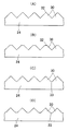
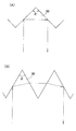
光学パターン30を金型成形する場合には、有効斜面率が低いほうが光学パターン30の製作が容易になる。金型製作をする場合、V溝部分などには必ずアールがつくためである。光学パターン30の有効斜面率が30%以下であれば、通常の機械加工で容易に金型を作製することができる。したがって、光学パターン30の有効斜面率は、図15のハッチング領域にあればよい。よって、図15によれば、光学パターン30の頂角φが73°以上82°以下、あるいは88°以上100°以下であれば、光学パターン用の金型製作が容易になり、また輝度分布の均一化にも寄与できることが分かる。特に、この範囲のうちでも、プリズム頂角φが90°の場合には、図16(A)に示すように1個の光学パターン30で主軸方向の光を回帰反射させることができ、またプリズム頂角φが75°の場合には、図16(B)に示すように2個の光学パターン30で主軸方向の光を回帰反射させることができる。よって、光学パターン30の頂角φが90°又は75°の場合には、光透過部32、33以外の領域において高い効率で光を回帰反射させることができ、光偏向プレート24の設計が容易になる。   When the optical pattern 30 is molded, the optical pattern 30 is easier to manufacture when the effective slope ratio is lower. This is because when the mold is manufactured, the V-groove portion is always rounded. If the effective slope ratio of the optical pattern 30 is 30% or less, the mold can be easily manufactured by ordinary machining. Therefore, the effective slope ratio of the optical pattern 30 may be in the hatched area of FIG. Therefore, according to FIG. 15, when the apex angle φ of the optical pattern 30 is 73 ° or more and 82 ° or less, or 88 ° or more and 100 ° or less, it becomes easy to manufacture a mold for the optical pattern, and the luminance distribution is reduced. It can be seen that it can also contribute to homogenization. Particularly in this range, when the prism apex angle φ is 90 °, the light in the principal axis direction can be recursively reflected by one optical pattern 30 as shown in FIG. When the apex angle φ is 75 °, the light in the principal axis direction can be recursively reflected by the two optical patterns 30 as shown in FIG. Therefore, when the apex angle φ of the optical pattern 30 is 90 ° or 75 °, the light can be recursively reflected with high efficiency in the region other than the light transmitting portions 32 and 33, and the design of the light deflection plate 24 is easy. become.

つぎに、光学パターン30を設ける領域について説明する。光学パターン30は、必ずしも光偏向プレート24の全面に設ける必要はなく、光源の主軸を中心とするある範囲内に設けてあればよい。図17に示す半径rの円形領域35は、光偏向プレート24の上面において最低限光学パターン30を設けておかなければならない領域である。Lzは光源22と光偏向プレート24の上面との間の距離である。θは、光源22から光偏向プレート24の上面のある点に引いた線分が、光源22の主軸となす角度である。   Next, a region where the optical pattern 30 is provided will be described. The optical pattern 30 is not necessarily provided on the entire surface of the light deflection plate 24, and may be provided within a certain range around the main axis of the light source. A circular region 35 having a radius r shown in FIG. 17 is a region where the optical pattern 30 must be provided at least on the upper surface of the light deflection plate 24. Lz is the distance between the light source 22 and the upper surface of the light deflection plate 24. θ is an angle formed by a line segment drawn from the light source 22 to a point on the upper surface of the light deflection plate 24 with the main axis of the light source 22.

光源22からLzだけ離れた平面(光偏向プレート24の上面)において、光源22の主軸とθの角度をなす方向における光量は、つぎのI(θ)で表される。
I(θ)=k×sinθ×cosθ/〔tan(θ+Δθ)−tan(θ−Δθ)〕
ここで、nは光源22の指向性を表すパラメータであって、例えばランバート光ではn=1となる。Δθは微小な角度変化で、0.1°程度であればよい。kは任意の定数であるが、I(0.0001)=1となるように決められる。I(0.0001)=1となるように規格化したとき、光偏向プレート24の上面には、少なくともI(θ)≧0.8を満たす円形領域内に、先に示した頂角と有効斜面率を持つ光学パターン30を設ければよい。したがって、最低限光学パターン30を設けなければならない円形領域35の半径rは、次の2式より定まる。
I(θ)=0.8
r=Lz×tanθ
In a plane (upper surface of the light deflection plate 24) separated from the light source 22 by Lz, the amount of light in a direction that forms an angle θ with the principal axis of the light source 22 is represented by the following I (θ).
I (θ) = k × sin θ × cos n θ / [tan 2 (θ + Δθ) −tan 2 (θ−Δθ)]
Here, n is a parameter representing the directivity of the light source 22, and for example, for Lambertian light, n = 1. Δθ is a slight change in angle and may be about 0.1 °. k is an arbitrary constant, but is determined so that I (0.0001) = 1. When standardized so that I (0.0001) = 1, the top angle of the optical deflection plate 24 and the above-described apex angle and effective are within a circular region satisfying at least I (θ) ≧ 0.8. An optical pattern 30 having a slope ratio may be provided. Therefore, the radius r of the circular region 35 where the optical pattern 30 must be provided at a minimum is determined by the following two formulas.
I (θ) = 0.8
r = Lz × tanθ

上記のような光学パターン30の頂角に関する条件や有効斜面率に関する条件などは、少なくともこの円形領域35内で満たしていればよく、円形領域35の外側では満たしていなくても差し支えない。   The above-described conditions related to the apex angle of the optical pattern 30 and the conditions related to the effective slope ratio may be satisfied at least in the circular region 35, and may not be satisfied outside the circular region 35.

なお、輝度分布の不均一は、光源22の配列ピッチの大きな方向、すなわち図6(A)のX方向で起こりやすい。したがって、光偏向プレート24は、光学パターン30の配列方向が光源22の配列ピッチの大きな方向と平行となるように配置することが好ましい。   Note that the uneven luminance distribution tends to occur in the direction in which the arrangement pitch of the light sources 22 is large, that is, in the X direction in FIG. Accordingly, the light deflection plate 24 is preferably arranged so that the arrangement direction of the optical patterns 30 is parallel to the direction in which the arrangement pitch of the light sources 22 is large.

(その他の変形例) (Other variations)

光学パターン30は、一定のピッチで配列されている必要はない。たとえば、図18(A)に示すように、光学パターン30の配列ピッチが徐々に変化していてもよい。また、光学パターン30の大きさ(断面積)も一定である必要はない。図18(B)に示す例では、頂角が同じ光学パターン30を一定ピッチで配列しているが、光学パターン30の高さが徐々に変化している。また、図18(C)に示す例でも、頂角が同じ光学パターン30を一定ピッチで配列しているが、光学パターン30の頂部に設けた光透過部32の曲率半径を徐々に変化させている。なお、光学パターン30のピッチが大きいと光学パターン30が目に見えるので、光学パターン30のピッチは1mm以下であることが望ましい。また、光学パターン30の断面は左右非対称であっても差し支えない。   The optical patterns 30 need not be arranged at a constant pitch. For example, as shown in FIG. 18A, the arrangement pitch of the optical patterns 30 may be gradually changed. Further, the size (cross-sectional area) of the optical pattern 30 does not have to be constant. In the example shown in FIG. 18B, the optical patterns 30 having the same apex angle are arranged at a constant pitch, but the height of the optical pattern 30 gradually changes. In the example shown in FIG. 18C, the optical patterns 30 having the same apex angle are arranged at a constant pitch, but the radius of curvature of the light transmitting portion 32 provided on the top of the optical pattern 30 is gradually changed. Yes. In addition, since the optical pattern 30 is visible when the pitch of the optical pattern 30 is large, it is desirable that the pitch of the optical pattern 30 is 1 mm or less. Further, the cross section of the optical pattern 30 may be asymmetrical.

また、光偏向プレート24の光学パターン30を設けた面と反対面には、図19に示すように、微細な凹凸などの拡散パターン36を設けてもよい。かかる変形例によれば、光偏向プレート24で回帰反射する光の効率を調整することができるので、輝度分布の微調整を行うことができる。あるいは、光偏向プレート24を透明又は半透明の乳白色材料で成形したり、光偏向プレート24内に微細なビーズなどの拡散材料を分散させたりしてもよい。これらの場合にも、光偏向プレート24の内部で光を拡散させることで回帰反射する光の効率を調整することが可能になり、輝度分布の微調整を行うことができる。   Further, as shown in FIG. 19, a diffusion pattern 36 such as fine irregularities may be provided on the surface opposite to the surface on which the optical pattern 30 of the light deflection plate 24 is provided. According to such a modification, the efficiency of light that is retro-reflected by the light deflection plate 24 can be adjusted, so that the brightness distribution can be finely adjusted. Alternatively, the light deflection plate 24 may be formed of a transparent or translucent milky white material, or a diffusion material such as fine beads may be dispersed in the light deflection plate 24. Also in these cases, it is possible to adjust the efficiency of the light that is recursively reflected by diffusing the light inside the light deflection plate 24, and fine adjustment of the luminance distribution can be performed.

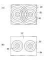
また、図20−図23は、種々の光学パターン30を表している。図20(A)は、2個の光源22が横に並んでいる場合である。この場合には、光源22どうしを結ぶ方向に直交する方向に光学パターン30が延びていることが望ましい。また、図20(B)に示すように、光源22のピッチが短い方向と平行に光学パターン30が配列していても差し支えない。また、図17において説明した光学パターン30の必要な円形領域35の外側であれば光学パターン30のない領域があってもよい。たとえば、図20(C)では、光源22間の中央部に光学パターン30のない領域37を設けている。ただし、光学パターン30のある領域と光学パターン30のない領域をはっきり分けると、その境界が目で見えてしまうので、グラデーションを入れて徐々に光学パターン30をなくすことが望ましい。   20 to 23 show various optical patterns 30. FIG. FIG. 20A shows a case where two light sources 22 are arranged side by side. In this case, it is desirable that the optical pattern 30 extends in a direction orthogonal to the direction connecting the light sources 22. Further, as shown in FIG. 20B, the optical pattern 30 may be arranged in parallel with the direction in which the pitch of the light sources 22 is short. Further, there may be a region without the optical pattern 30 as long as it is outside the necessary circular region 35 of the optical pattern 30 described in FIG. For example, in FIG. 20C, a region 37 without the optical pattern 30 is provided in the central portion between the light sources 22. However, if the region with the optical pattern 30 and the region without the optical pattern 30 are clearly separated, the boundary is visible with eyes, so it is desirable to gradually eliminate the optical pattern 30 by adding gradation.

図21(A)は、四角錐形状(ピラミッド形状)又は四角錐台形状の光学パターン30を格子状に配列したものである。この場合にも、図21(B)のように光学パターン30のない領域37を設けてもよい。このような形状の光学パターン30の場合には、有効斜面率は光偏向プレート24に垂直な方向から見た面積を用いて計算すればよい。   FIG. 21A shows an optical pattern 30 having a quadrangular pyramid shape (pyramid shape) or a quadrangular pyramid shape arranged in a lattice pattern. Also in this case, a region 37 without the optical pattern 30 may be provided as shown in FIG. In the case of the optical pattern 30 having such a shape, the effective slope ratio may be calculated using the area viewed from the direction perpendicular to the light deflection plate 24.

図22(A)又は図22(B)のように光源22が斜めに並んでいる場合には、斜め方向に延びた光学パターン30を斜め方向に配列させてもよい。   When the light sources 22 are arranged obliquely as shown in FIG. 22A or FIG. 22B, the optical patterns 30 extending in the oblique direction may be arranged in the oblique direction.

また、図23(A)に示すように、光源22の主軸位置を中心として同心円状に光学パターン30を配置してもよい。この場合にも、図21(B)のように光学パターン30のない領域37を設けてもよい。   Further, as shown in FIG. 23A, the optical pattern 30 may be arranged concentrically around the main axis position of the light source 22. Also in this case, a region 37 without the optical pattern 30 may be provided as shown in FIG.

Claims (7)

押ボタンと、
前記押ボタンの操作により接点間を開閉する接点開閉機構部と、
前記押ボタンの操作により点灯または消灯する複数個の光源と、
を備えた照光スイッチにおいて、
前記光源に対向させて光偏向プレートを設け、
前記光偏向プレートの前記光源と反対側の面の、少なくとも前記光源の主軸付近に共通な一方向に延びた複数条の光学パターンと光透過部とを設けてあり、
前記光学パターンは、頂角が67°以上105°以下となる一対の傾斜面を有する断面三角プリズム状に形成され、
前記光透過部は、前記光学パターンの稜線または谷線部分に沿って設けられた、平坦面または緩やかな曲面または前記傾斜面よりも緩やかな傾斜角の傾斜面のいずれかによって形成され、
複数個の前記光源は、前記光学パターンの延びている方向と直交する方向に沿った間隔が、前記光学パターンの延びている方向に沿った間隔よりも大きくなるように配置されていることを特徴とする照光スイッチ。
A push button,
A contact opening / closing mechanism that opens and closes the contacts by operating the push button;
A plurality of light sources that are turned on or off by the operation of the push buttons;
In an illuminated switch with
A light deflection plate is provided opposite the light source,
The light source of the light deflection plate opposite to the surface, is provided with at least the light Science in plural rows extending in a common direction around the main axis of the light source pattern and the light transmitting portion,
The optical pattern is formed in a triangular triangular prism shape having a pair of inclined surfaces with an apex angle of 67 ° to 105 °,
The light transmission portion is formed by either a flat surface, a gently curved surface, or an inclined surface having a gentler inclination angle than the inclined surface, provided along a ridge line or a valley line portion of the optical pattern,
The plurality of light sources are arranged such that an interval along a direction orthogonal to an extending direction of the optical pattern is larger than an interval along the extending direction of the optical pattern. Illuminated switch.
4個の前記光源が矩形状に配置されていることを特徴とする、請求項1に記載の照光スイッチ。 The illumination switch according to claim 1, wherein the four light sources are arranged in a rectangular shape . 前記光偏向プレートの表面において、少なくとも前記光源の主軸から次式:
r=Lz×tanθ
I(θ)=k×sinθ×cosθ/〔tan(θ+Δθ)−tan(θ−Δθ)〕=0.8
ただし、Lzは光源と光偏向プレートとの距離
Δθ=0.1
kはI(0.0001)=1によって決まる値
nは前記光源の指向性を表すパラメータ
で決まる半径rの範囲内に光学パターンを設けていることを特徴とする、請求項1に記載の照光スイッチ。
On the surface of the light deflection plate, at least from the main axis of the light source:
r = Lz × tanθ
I (θ) = k × sin θ × cos n θ / [tan 2 (θ + Δθ) −tan 2 (θ−Δθ)] = 0.8
Where Lz is the distance between the light source and the light deflection plate
Δθ = 0.1
k is a value determined by I (0.0001) = 1
The illumination switch according to claim 1, wherein an optical pattern is provided in a range of a radius r determined by a parameter n representing the directivity of the light source .
前記光源の主軸付近における前記光学パターンの頂角が、73°以上82°以下もしくは88°以上100°以下であることを特徴とする、請求項に記載の照光スイッチ。 2. The illumination switch according to claim 1 , wherein an apex angle of the optical pattern in the vicinity of a main axis of the light source is 73 ° to 82 ° or 88 ° to 100 °. 前記光偏向プレートは、透明又は半透明の乳白色材料によって形成されていることを特徴とする、請求項1に記載の照光スイッチ。   The illumination switch according to claim 1, wherein the light deflection plate is made of a transparent or translucent milky white material. 前記光偏向プレートに、微細な光拡散材を分散させていることを特徴とする、請求項1に記載の照光スイッチ。   2. The illumination switch according to claim 1, wherein a fine light diffusing material is dispersed in the light deflection plate. 前記光偏向プレートの、前記光学パターンを形成された面に対して反対側の面に、光を拡散させるための凹凸を形成したことを特徴とする、請求項1に記載の照光スイッチ。   2. The illumination switch according to claim 1, wherein unevenness for diffusing light is formed on a surface of the light deflection plate opposite to the surface on which the optical pattern is formed.
JP2013127952A 2013-06-18 2013-06-18 Illuminated switch Active JP6232768B2 (en)

Priority Applications (3)

Application Number Priority Date Filing Date Title
JP2013127952A JP6232768B2 (en) 2013-06-18 2013-06-18 Illuminated switch
CN201420274328.8U CN203895304U (en) 2013-06-18 2014-05-27 Light irradiation switch
CN201410227748.5A CN104240997B (en) 2013-06-18 2014-05-27 Irradiation is switched

Applications Claiming Priority (1)

Application Number Priority Date Filing Date Title
JP2013127952A JP6232768B2 (en) 2013-06-18 2013-06-18 Illuminated switch

Publications (2)

Publication Number Publication Date
JP2015002165A JP2015002165A (en) 2015-01-05
JP6232768B2 true JP6232768B2 (en) 2017-11-22

Family

ID=51721674

Family Applications (1)

Application Number Title Priority Date Filing Date
JP2013127952A Active JP6232768B2 (en) 2013-06-18 2013-06-18 Illuminated switch

Country Status (2)

Country Link
JP (1) JP6232768B2 (en)
CN (2) CN104240997B (en)

Families Citing this family (2)

* Cited by examiner, † Cited by third party
Publication number Priority date Publication date Assignee Title
JP6232768B2 (en) * 2013-06-18 2017-11-22 オムロン株式会社 Illuminated switch
JP6413852B2 (en) * 2015-03-10 2018-10-31 オムロン株式会社 Push-button switch

Family Cites Families (8)

* Cited by examiner, † Cited by third party
Publication number Priority date Publication date Assignee Title
JPH078805U (en) * 1993-06-29 1995-02-07 第二しなのポリマー株式会社 Directional diffuser and its applications
FR2812966B1 (en) * 2000-08-11 2002-12-20 Telecomm Electronique Aeronaut MULTI-MESSAGE LUMINOUS BUTTON WITH INDEPENDENT LIGHTS, ESPECIALLY FOR AERONAUTICAL EQUIPMENT FACADE, AND BAR CONSISTING OF SUCH BUTTONS
JP2006134715A (en) * 2004-11-05 2006-05-25 Fujikura Ltd Switch structure
JP4826414B2 (en) * 2006-09-28 2011-11-30 オムロン株式会社 Push button switch
US7455416B2 (en) * 2006-11-17 2008-11-25 Ichia Technologies, Inc. Light guide structure and keypad having the same
CN201262908Y (en) * 2008-07-29 2009-06-24 达方电子股份有限公司 Keycap as well as key structure and keyboard with the same
JP5274537B2 (en) * 2010-11-19 2013-08-28 オムロン株式会社 Illuminated pushbutton switch and operation panel
JP6232768B2 (en) * 2013-06-18 2017-11-22 オムロン株式会社 Illuminated switch

Also Published As

Publication number Publication date
CN203895304U (en) 2014-10-22
CN104240997B (en) 2017-08-25
JP2015002165A (en) 2015-01-05
CN104240997A (en) 2014-12-24

Similar Documents

Publication Publication Date Title
CN104696780B (en) Backlight module and light source assembly thereof
US7582913B2 (en) Lens and LED using the lens to achieve homogeneous illumination
KR101264323B1 (en) Plane light emitting back light unit and lamp using point light source
JP5510038B2 (en) Collimated light source and surface light source device
JP5429633B2 (en) Surface light emitting device and liquid crystal display device
JP2005135844A (en) Optical element and backlight device
US10634296B2 (en) Luminous flux control member, light-emitting device, planar light source device, and display device
JP2018061024A (en) Light beam control member, light-emitting device and illuminating device
JPH0868997A (en) Liquid crystal display device
CN105911631B (en) Light guide and light emitting device
JP6232768B2 (en) Illuminated switch
JP7024399B2 (en) Light source unit and lighting equipment
JP6390194B2 (en) Optical element and surface light source device
JP6108104B2 (en) Light deflection plate, surface light source device, and illumination switch
JP2018142418A (en) Light emitting device, surface light source device and display device
TW202001380A (en) Planar lighting device
CN111051769A (en) Light emitting device, surface light source device, and display device
KR101535906B1 (en) Backlight Unit
JP2012164435A (en) Planar light source device and liquid crystal display
JP2012145829A (en) Light-emitting device and luminaire
JP6733317B2 (en) Window lighting equipment
JP6751452B2 (en) Area lighting device
CN111373194B (en) Lighting device
WO2021187571A1 (en) Light flux control member, light-emitting device, area light source device, and display device
JP4725434B2 (en) Prism for switch

Legal Events

Date Code Title Description
A621 Written request for application examination

Free format text: JAPANESE INTERMEDIATE CODE: A621

Effective date: 20160509

A977 Report on retrieval

Free format text: JAPANESE INTERMEDIATE CODE: A971007

Effective date: 20170228

A131 Notification of reasons for refusal

Free format text: JAPANESE INTERMEDIATE CODE: A131

Effective date: 20170307

A521 Written amendment

Free format text: JAPANESE INTERMEDIATE CODE: A523

Effective date: 20170427

TRDD Decision of grant or rejection written
A01 Written decision to grant a patent or to grant a registration (utility model)

Free format text: JAPANESE INTERMEDIATE CODE: A01

Effective date: 20170926

A61 First payment of annual fees (during grant procedure)

Free format text: JAPANESE INTERMEDIATE CODE: A61

Effective date: 20171009

R150 Certificate of patent or registration of utility model

Ref document number: 6232768

Country of ref document: JP

Free format text: JAPANESE INTERMEDIATE CODE: R150