JP6232103B1 - Bathing bath for both baths - Google Patents
Bathing bath for both baths Download PDFInfo
- Publication number
- JP6232103B1 JP6232103B1 JP2016108513A JP2016108513A JP6232103B1 JP 6232103 B1 JP6232103 B1 JP 6232103B1 JP 2016108513 A JP2016108513 A JP 2016108513A JP 2016108513 A JP2016108513 A JP 2016108513A JP 6232103 B1 JP6232103 B1 JP 6232103B1
- Authority
- JP
- Japan
- Prior art keywords
- frame
- bathtub
- chair
- sitting
- sleeping
- Prior art date
- Legal status (The legal status is an assumption and is not a legal conclusion. Google has not performed a legal analysis and makes no representation as to the accuracy of the status listed.)
- Expired - Fee Related
Links
Images
Landscapes
- Devices For Medical Bathing And Washing (AREA)
Abstract
【課題】高齢者や身体障害者などの要介護者の入浴をさせるに際し、1台で寝浴形式でも座浴形式でも利用できる入浴装置を提供する。【解決手段】寝浴用ストレッチャーEに仰臥した入浴者および座浴用椅子Fに座った入浴者の両方とも入浴可能とする入浴装置Aであって、寝浴用の長尺の浴槽Bと、寝浴用ストレッチャーEを浴槽Bの長辺側縁b1に接近させた状態で、浴槽Bを寝浴用ストレッチャーE上の入浴者を入浴させうる高位置まで上昇させ、かつ寝浴用ストレッチャーEを進入退避させることが可能な低位置まで下降させうる浴槽昇降機Cと、浴槽Bの短辺側縁b2の外方に設置された、座浴用椅子Fを搬入搬出する椅子搬出入機Dとを備える。寝浴用ストレッチャーEに仰臥した入浴者および座浴用椅子Fに座った入浴者の両方とも入浴可能とすることができる。【選択図】図1Provided is a bathing apparatus that can be used in a sleeping or sitting mode when one person takes care of a care recipient such as an elderly person or a physically handicapped person. SOLUTION: A bathing apparatus A capable of bathing both a bather lying on a stretcher E for sleeping and a bather sitting on a sitting chair F, and has a long bathtub B for sleeping and a sleeping bath. With the stretcher E approaching the long side edge b1 of the bathtub B, the bathtub B is raised to a high position where the bather on the sleeper stretcher E can take a bath, and the sleeper stretcher E enters and retreats. A bathtub lift C that can be lowered to a low position where it can be moved, and a chair loading / unloading machine D that loads and unloads a seating chair F installed outside the short side edge b2 of the bathtub B. Both the bather who is lying on the sleeping bath stretcher E and the bather who is sitting on the sitting chair F can be made bathable. [Selection] Figure 1
Description
本発明は、寝浴座浴両用入浴装置に関する。さらに詳しくは、高齢者や身体障害者などの要介護者の入浴をさせるに際し寝浴形式でも座浴形式でも行える入浴装置に関する。 [0001] The present invention relates to a bathing apparatus for both bathing and sitting. More particularly, the present invention relates to a bathing apparatus that can be used in the form of a sleeping bath or a sitting bath when bathing a care recipient such as an elderly person or a disabled person.
従来より要介護者用の入浴装置には、座浴形式のもの(特許文献1ほか多数)と、寝浴形式のもの(特許文献2、3ほか多数)とがある。座浴形式とは入浴者が椅子に座った姿勢で浴槽内につかるものであり、寝浴形式とは入浴者がストレッチャーに仰臥した姿勢で浴槽内につかるものである。
Conventionally, there are two types of bathing devices for care recipients: a sitting bath type (
座浴形式の入浴装置は、入浴者が座る椅子と浴槽と椅子を浴槽と洗い場との間で移動させる搬出入機とが必要となる。
寝浴形式の入浴装置は、入浴者が寝るストレッチャーと浴槽とストレッチャーを浴槽に出し入れする浴槽昇降機とが必要となる。また、寝浴用の浴槽は、人の身長より長くなくてはならないので、座浴用の浴槽よりも長いものとなる。
The bathing apparatus of the sitting bath type requires a chair on which a bather sits, a bathtub, and a carry-in / out machine that moves the chair between the bathtub and the washing area.
The bathing apparatus of the sleeping bath type requires a stretcher for a bather to sleep, a bathtub, and a bathtub lift for taking the stretcher into and out of the bathtub. In addition, since the bathing tub must be longer than the height of the person, it is longer than the bathing tub.
座浴用入浴装置と寝浴用入浴装置は要求される機能が異なることから構造も大きさも異なっており、それらは兼用できず個別に設置されるのが普通であった。
しかるに、小規模な介護施設では座浴用入浴装置と寝浴用入浴装置を両方とも設置するスペースが無かったり、費用の面で設置困難なこともある。
The bathing apparatus for sitting bath and the bathing apparatus for sleeping are different in structure and size because they require different functions, and they cannot be used in common and are usually installed individually.
However, in a small-scale care facility, there is no space for installing both a bathing device for sitting bath and a bathing device for sleeping, and it may be difficult to install due to cost.
本発明は上記事情に鑑み、高齢者や身体障害者などの要介護者の入浴をさせるに際し、1台で寝浴形式でも座浴形式でも利用できる入浴装置を提供することを目的とする。 In view of the above circumstances, an object of the present invention is to provide a bathing apparatus that can be used in a single bathing style or a sitting style when bathing a care recipient such as an elderly person or a disabled person.
第1発明の寝浴座浴両用入浴装置は、寝浴用ストレッチャーに仰臥した入浴者および座浴用椅子に座った入浴者の両方とも入浴可能とする入浴装置であって、寝浴用の長尺の浴槽と、前記寝浴用ストレッチャーを前記浴槽の長辺側縁に接近させた状態で、該浴槽を寝浴用ストレッチャー上の入浴者を入浴させうる高位置まで上昇させ、かつ該寝浴用ストレッチャーを進入退避させることが可能な低位置まで下降させうる浴槽昇降機と、前記浴槽の短辺側縁の外方に設置された、座浴用椅子を搬入搬出する椅子搬出入機と、前記椅子搬出入機が、基台と、前記基台上に設けられ、前記浴槽に対して水平方向に移動可能な横移動手段と、前記横移動手段上に設けられ、前記浴槽に対して上下方向に移動可能な昇降手段と、前記昇降手段に取付けられた座浴用椅子を着脱自在に係着する椅子係着部とを備えており、前記横移動手段が、横フレーム機構と該横フレーム機構を作動させる水圧シリンダと前記横フレーム機構の作動をガイドする横ガイド機構とからなり、前記横フレーム機構は、基台上に取付けられた基端フレームと、該基端フレームに対し横移動自在な中間フレームと、該中間フレームに対して横移動自在な先端フレームとからなり、前記横ガイド機構は、前記中間フレームに取付けられたガイドバーが、前記基端フレームに取付けられたガイドローラと前記先端フレームに取付けられたガイドローラで挟まれており、前記先端フレームは前記基端フレームに取付けられた固定ローラでガイドされるガイド構造であり、前記昇降手段が縦フレーム機構と該縦フレーム機構を作動させる水圧シリンダと前記縦フレーム機構の作動をガイドする縦ガイド機構とからなり、前記縦フレーム機構は、下段フレームと該下段フレームに対して昇降自在な上段フレームとからなることを特徴とする。
第2発明の寝浴座浴両用入浴装置は、第1発明において、前記縦ガイド機構は、前記下段フレームに取付けたガイドローラで、前記上段フレームに取付けたガイドバーを挟んでガイドするガイド構造からなり、前記水圧シリンダの駆動源が電池であることを特徴とする。
The bathing apparatus for both bathing and sitting areas according to the first invention is a bathing apparatus that allows both a bather lying on a sleeping stretcher and a bather sitting on a sitting chair, and is a long bathtub for sleeping And with the stretcher for sleeping close to the long side edge of the bathtub, the bathtub is raised to a high position where a bather on the stretcher for sleeping can be bathed, and the stretcher for sleeping is Bathtub elevator which can be lowered to a low position where entry and retraction can be performed, chair carry-in / out machine installed on the outer side of the short side edge of the bathtub, for loading / unloading a seating chair, and the chair carry-in / out machine Are provided on the base, the horizontal movement means provided on the base and movable in the horizontal direction with respect to the bathtub, and provided on the horizontal movement means and movable in the vertical direction with respect to the bathtub. Elevating means and attached to the elevating means A chair engaging portion for detachably attaching the chair for sitting bath, and the lateral movement means guides the operation of the lateral frame mechanism, the hydraulic cylinder for operating the lateral frame mechanism, and the operation of the lateral frame mechanism. The horizontal frame mechanism includes a base frame mounted on a base, an intermediate frame movable laterally with respect to the base frame, and a distal end movable laterally with respect to the intermediate frame. The lateral guide mechanism is configured such that a guide bar attached to the intermediate frame is sandwiched between a guide roller attached to the proximal frame and a guide roller attached to the distal end frame, The frame has a guide structure guided by a fixed roller attached to the base end frame, and the elevating means creates a vertical frame mechanism and the vertical frame mechanism. Consists of a longitudinal guide mechanism for guiding the operation of the hydraulic cylinder and the longitudinal frame mechanism for the vertical frame mechanism is characterized by comprising a vertically movable upper frame to the lower frame and the lower stage frame.
According to a second aspect of the present invention, there is provided a bathing apparatus for both bathing and sitting baths according to the first invention, wherein the vertical guide mechanism is a guide roller that is guided by a guide roller attached to the lower frame, with a guide bar attached to the upper frame interposed therebetween. The drive source of the hydraulic cylinder is a battery.
第1発明によれば、つぎの効果を奏する。
a)浴槽昇降機を使えば、浴槽を寝浴用ストレッチャー上の入浴者を入浴させうる高位置まで上昇させ、かつ寝浴用ストレッチャーを進入退避させることが可能な低位置まで下降させうる。また、搬出入機を使えば、人が座った座浴用椅子を浴槽内へ搬入したり浴槽外へ搬出することができる。このため、寝浴用ストレッチャーに仰臥した入浴者および座浴用椅子に座った入浴者の両方とも入浴可能とすることができる。
b)椅子搬出入機における横移動手段は横フレーム機構を横ガイド機構で案内し、昇降手段は縦フレーム機構を縦ガイド機構で案内する構造なので、水平の維持度も高く垂直の維持度も高い。このため、撓みやこじりによる抵抗は生じない。このため、移動抵抗は非常に小さくなっている。
c)前記横移動手段はガイドバーをガイドローラで挟んでガイドする構造なので、水平の維持度が高く、撓みやこじりによる抵抗は生じない。しかもガイドローラによる転動を用いるので移動抵抗は非常に小さくなっている。このため、水圧シリンダの動力源が電池であっても充分駆動できる。したがって、従来の交流電源を使用する場合に比べて、漏電による感電のおそれがなく、高齢者や身体障害者にとって特に重要な安全性の向上が図られる。
第2発明によれば、昇降手段はガイドバーをガイドローラで挟んでガイドする構造なので、垂直の維持度が高く、撓みやこじりによる抵抗は生じない。しかもガイドローラによる転動を用いるので移動抵抗は非常に小さくなっている。このため、水圧シリンダの動力源が電池であっても充分駆動できる。したがって、従来の交流電源を使用する場合に比べて、漏電による感電のおそれがなく、高齢者や身体障害者にとって特に重要な安全性の向上が図られる。
According to the first invention, the following effects are obtained.
a) If the bathtub elevator is used, the bathtub can be raised to a high position where the bather on the sleeping stretcher can take a bath, and can be lowered to a low position where the sleeping stretcher can enter and retreat. In addition, if a carry-in / out machine is used, a chair for sitting on a person can be carried into the bathtub or carried out of the bathtub. For this reason, both the bather who lies on the stretcher for sleeping and the bather who sits on the chair for sitting can take a bath.
b) Since the horizontal movement means in the chair loading / unloading machine guides the horizontal frame mechanism with the horizontal guide mechanism and the lifting means guides the vertical frame mechanism with the vertical guide mechanism, the horizontal maintenance degree is high and the vertical maintenance degree is also high. . For this reason, no resistance due to bending or twisting occurs. For this reason, the movement resistance is very small.
c) The lateral movement means has a structure in which a guide bar is sandwiched between guide rollers, so that the horizontal maintenance degree is high and resistance due to bending or twisting does not occur. Moreover, since the rolling by the guide roller is used, the movement resistance is very small. For this reason, even if the power source of the hydraulic cylinder is a battery, it can be driven sufficiently. Therefore, compared with the case where a conventional AC power supply is used, there is no fear of electric shock due to electric leakage, and safety that is particularly important for elderly people and persons with physical disabilities can be improved.
According to the second aspect of the present invention, the elevating means has a structure in which the guide bar is sandwiched and guided by the guide roller, so that the degree of vertical maintenance is high and resistance due to bending or twisting does not occur. Moreover, since the rolling by the guide roller is used, the movement resistance is very small. For this reason, even if the power source of the hydraulic cylinder is a battery, it can be driven sufficiently. Therefore, compared with the case where a conventional AC power supply is used, there is no fear of electric shock due to electric leakage, and safety that is particularly important for elderly people and persons with physical disabilities can be improved.
つぎに、本発明の実施形態を図面に基づき説明する。
本発明の入浴装置は、高齢者や身体障害者などの要介護者を寝浴形式でも座浴形式でも入浴させうる寝浴座浴両用入浴装置(以下、入浴装置という)である。
Next, an embodiment of the present invention will be described with reference to the drawings.
The bathing apparatus according to the present invention is a bathing / bathing bathing apparatus (hereinafter referred to as a bathing apparatus) capable of bathing a care recipient such as an elderly person or a physically handicapped person in a sleeping or sitting manner.
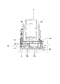
(全体構成)
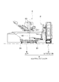
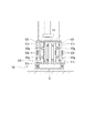
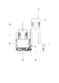
図1および図2に示すように、本実施形態の入浴装置Aは、寝浴用の浴槽Bとこの浴槽Bを昇降させる浴槽昇降機Cと、座浴用椅子を浴槽Bに搬出入させる椅子搬出入機Dとからなる。
なお、要介護者を入浴させるために用いるストレッチャーEと座浴用椅子Fは、本発明の構成要件ではないが、入浴時には利用される。
(overall structure)
As shown in FIGS. 1 and 2, a bathing apparatus A according to the present embodiment includes a bath B for sleeping, a bath elevator C that lifts and lowers the bathtub B, and a chair loading / unloading machine that allows a seating chair to be carried in and out of the bathtub B. D.
The stretcher E and the sitting bath chair F used for bathing care recipients are not constituent elements of the present invention, but are used during bathing.
(浴槽B)
図1および図2に示す浴槽Bは、寝浴用の浴槽である。浴槽には寝浴用の浴槽と座浴用の浴槽の2種類があるが、寝浴用の浴槽は人が仰臥した姿勢で利用するので座浴用の浴槽に比べて長さが長いものが用いられる。なお、座浴には寝浴用の浴槽を使いうることは勿論である。
(Bathtub B)
The bathtub B shown in FIGS. 1 and 2 is a bathing bath. There are two types of bathtubs, a sleeping bath and a sitting bath. However, since the sleeping bath is used in a posture where a person is supine, a bath having a longer length than the sitting bath is used. Of course, a sleeping bath can be used for sitting.
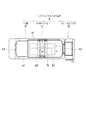
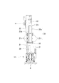
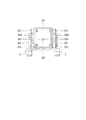
図2に示すように、浴槽Bは平面視で長方形であって、一対の長辺縁b1と一対の短辺縁b2とを有する。長辺縁b1はストレッチャーEが接近する側であり、短辺縁b2は椅子搬出入機Dが設置される側である。
図2に点線図示するように、浴槽Bの下面には浴槽昇降機Cが設置され(図1には示していない)、この浴槽昇降機Cによって浴槽Bが昇降するようになっている。
As shown in FIG. 2, the bathtub B is rectangular in plan view, and has a pair of long side edges b1 and a pair of short side edges b2. The long side edge b1 is the side on which the stretcher E approaches, and the short side edge b2 is the side on which the chair carry-in / out machine D is installed.
2, a bathtub elevator C is installed on the lower surface of the bathtub B (not shown in FIG. 1), and the bathtub B is moved up and down by the bathtub elevator C.
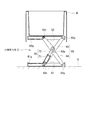
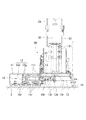
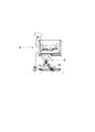
(浴槽昇降機C)
図2および図3に示すように、浴槽昇降機Cは、浴槽Bの下面と床面Gとの間に設置された、浴槽Bを昇降させる昇降機構である。浴槽昇降機Cの基本構成は、床面Gに設置される下フレーム61と浴槽Bの底面に取付けられた上フレーム62と、これら下フレーム61および上フレーム62との間に連結されたパンダグラフ機構63と、このパンタグラフ機構63を伸縮させる水圧シリンダ70とからなる。
(Bathtub elevator C)
As shown in FIGS. 2 and 3, the bathtub elevator C is a lifting mechanism that is installed between the lower surface of the bathtub B and the floor surface G and moves the bathtub B up and down. The basic structure of the bathtub elevator C includes a
パンタグラフ機構63は、第1リンク64と第2リンク65を備えており、両リンク64、65の中間部はピン63pで枢支され、第1リンク64の下端は下フレーム61の一端部にピン64pで枢支され、第2リンク65の上端は上フレーム62の一端部にピン65pで枢支されている。
他方、第1リンク64の上端に軸支されているローラ64rは上フレーム62に形成されたガイド部62g内を転動し、第2リンク65の下端に軸支されているローラ65rは下フレーム61に形成されたガイド部61g内を転動するようになっている。
The
On the other hand, the
そして、水圧シリンダ70のシリンダ部71は第2リンク65に連結され、ロッド72は第1リンク64に連結されている。このため、水圧シリンダ70を伸縮させるとパンタグラフ機構63を構成する第1、第2リンク64、65は開閉動作をして、高さ寸法が高低に変動する。このため、浴槽Bを昇降させることができる。
The
(ストレッチャーE)
図1に示すストレッチャーEは公知のもので、台車81と支柱82とベッド83とからなる。図示のストレッチャーEは例示であって、公知のストレッチャーのどのようなものも本発明に利用できる。
図1に示すストレッチャーEの台車81は、図2に示す浴槽昇降機Cに干渉することなく、下降位置にある浴槽Bの下面に進入でき、この状態でベッド83を浴槽Bの上方に位置させることができる。つまり、図1に示す状態で、浴槽Bを上昇させるとベッド83上に仰臥した要介護者を湯舟につかすことができる。
(Stretcher E)
The stretcher E shown in FIG. 1 is a known one and includes a
The
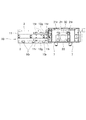
(座浴用の椅子搬出入機D)
椅子搬出入機Dを図4〜図11に基づき説明する。図4および図5は、図1と同様の移動前姿勢を示し、図6〜図8は移動後姿勢を示す。椅子搬出入機Dの基本構成は、横移動手段1と昇降手段2が基台3上に設けられた構造であり、移動前姿勢は横移動手段1が横移動しておらず、昇降手段2が下降している状態をいう。移動後姿勢は横移動手段1が横移動しており、かつ昇降手段2が上昇している状態をいう。
(Chair carry-in / out machine D for sitting bath)
The chair carry-in / out machine D will be described with reference to FIGS. 4 and 5 show the pre-movement postures similar to those in FIG. 1, and FIGS. 6 to 8 show the post-movement postures. The basic structure of the chair loading / unloading machine D is a structure in which the lateral movement means 1 and the lifting / lowering means 2 are provided on the
基台3は、浴槽Bの短辺縁b2の外に付設される。浴槽Bに基台3を付設する際、図1および図2における基台3の右側にスペースを確保する必要は無く、浴室の壁に隣接して基台3を設置することができる。
基台3上には、横移動手段1が設けられており、この横移動手段1上には昇降手段2が設けられている。なお、昇降手段2には、座浴用の椅子Fの椅子係着部7が取付けられている。
The
A lateral movement means 1 is provided on the
横移動手段1は、昇降手段2を浴槽Bに対して接近離間するように移動させる機能を有する。つまり、横移動手段1により昇降手段2は、図13に示す使用位置Uと準備位置Sとの間で移動できる。なお、使用位置Uとは椅子Dを浴槽B内に降ろせる位置であり、準備位置Sとは椅子Dを洗い場に降ろせる位置である。
昇降手段2は、椅子係着部7を降下位置Lと上昇位置Hとの間で昇降させる機能を有している。降下位置Lは浴槽B内や洗い場Cで椅子Dを下した位置であり、上昇位置Hは椅子Dを浴槽Bのヘリを乗り越える位置である。
The lateral movement means 1 has a function of moving the elevating
The elevating means 2 has a function of elevating and lowering the
つぎに、横移動手段1の構成を図4〜図8に基づいて説明する。
横移動手段1は、横フレーム機構と水圧シリンダと横ガイド機構からなる。
横フレーム機構は、図5および図7に示すように、基台3上に取り付けられた基端フレーム11と、中間フレーム12と先端フレーム13とを有している。本実施形態は先端フレーム13を手動で引き出すタイプであるが、動力化する場合は基端フレーム11の基端部(図中の左端)と先端フレーム13の先端部(図中の右端)との間に水圧シリンダを取付ければよい。
Next, the configuration of the lateral movement means 1 will be described with reference to FIGS.
The lateral movement means 1 includes a lateral frame mechanism, a hydraulic cylinder, and a lateral guide mechanism.
As shown in FIGS. 5 and 7, the horizontal frame mechanism has a
横フレーム機構の詳細と横ガイド機構をさらに説明する。
前記基端フレーム11は、左右一対の立板と底板とからなる。この基端フレーム11の左右一対の立板における上段部と下段部のそれぞれにおいて、ガイドローラ11rが複数個づつ取付けられている。複数個のガイドローラ11rは先端フレーム13の移動方向に沿って間隔をあけて取付けられている。
基端フレーム11の底板上には固定ローラ10rが複数個取付けられている。複数個の固定ローラ10rは先端フレーム13の走行方向に沿って設けられており、先端フレーム13を走行自在に支持している。
Details of the lateral frame mechanism and the lateral guide mechanism will be further described.
The
On the bottom plate of the
前記中間フレーム12は、前後2枚の端面板12eを有し、それらの間に上下一対のガイドバー12gを左右に備えて構成されている。
The
前記先端フレーム13は、左右一対の立板と先端側の端面板とからなる。先端フレーム13における左右一対の立板の中段部において、上段部と下段部のそれぞれに、ガイドローラ13rが複数個づつ取付けられている。複数個のガイドローラ13rは先端フレーム13の移動方向に沿って間隔をあけて取付けられている。
The
中間フレーム12のガイドバー12gは基端フレーム11のガイドローラ11rと先端フレーム13のガイドローラ13rで上下から挟まれており、中間フレーム12が基端フレーム11に対し伸縮自在であり、先端フレーム13も固定ローラ10r上で伸縮自在である。本明細書では、この構造を横ガイド機構10という。
The
図7に示すように、先端フレーム13を手動で引き出すと中間フレームにも伸長し、先端フレーム13の先端部はローラ15で支えられ、後端部は中間フレーム12で支えられる。手動で先端フレーム13を押し戻すと、図5に示すように、先端フレーム13も中間フレーム12も基端フレーム11内に収められる。
As shown in FIG. 7, when the
図9の拡大図に示すように、横ガイド機構10は、中間フレーム12に取付けられたガイドバー12gが、基端フレーム11に取付けられたガイドローラ11rと先端フレーム13に取付けられたガイドローラ13rで挟まれており、先端フレーム13は基端フレーム11に取付けられた固定ローラ10rでガイドされるガイド構造である。
As shown in the enlarged view of FIG. 9, the
このように、ガイドバー12gをガイドローラ11r、13rで挟んでガイドする構造なので、水平の維持度も高く垂直の維持度も高い。このため、撓みやこじりによる抵抗は生じない。しかもガイドローラ11r、13rによる転動を用いるので移動抵抗は非常に小さくなっている。このため、人力でも軽い力で動くし、水圧シリンダを使ったとしても電池で充分駆動できる。
As described above, the
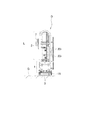
前記横移動手段1の上には、昇降手段2が立設されている。
昇降手段2は、図5、図7および図8に示すように、縦フレーム機構と水圧シリンダと縦ガイド機構からなる。
縦フレーム機構は、下段フレーム21と上段フレーム22と中間フレーム23とから構成されている。下段フレーム21は4枚の板材からなる断面四角形のフレームであり、上段フレーム22も3枚の板材からなる断面U形のフレームである。そして、下段フレーム21の下端と上段フレーム22の上端との間に水圧シリンダ30が取付けられている。
An elevating
As shown in FIGS. 5, 7, and 8, the lifting / lowering means 2 includes a vertical frame mechanism, a hydraulic cylinder, and a vertical guide mechanism.
The vertical frame mechanism includes a
下段フレーム21と上段フレーム22との間には、縦ガイド機構20が設けられている。この縦ガイド機構20は、下段フレーム21側に取付けたガイドローラ21rと中間フレーム23を構成する上下両端の固定板に取付けたガイドバー23bとから構成されている。この中間フレーム23は上段フレーム22の昇降に合わせて昇降するよう上段フレーム22から吊り下げるか、押し材で押し上げるようにされている。
A
上記に加え、上段フレーム22にガイドローラ22rを軸支し、ガイドバー23bを二つのガイドローラ21r、22rで挟むようにしてもよい。
In addition to the above, a
図10の拡大図に示すように、前記縦ガイド機構20は、前記下段フレーム21に取付けたガイドローラ21rでガイドバー23bを案内するか、または、さらに、前記上段フレーム22に取付けたガイドローラ22rで、ガイドバー23bを挟んでガイドするように構成される。
As shown in the enlarged view of FIG. 10, the
このように、ガイドバー23bを一方のをガイドローラ21rで案内するか、あるいは一対のガイドローラ21r、22rで挟んでガイドする構造なので、垂直の維持度が高い。このため、撓みやこじりによる抵抗は生じない。しかもガイドローラ21r、22rによる転動を用いるので移動抵抗は非常に小さくなっている。このため、水圧シリンダ30の動力源が電池であっても充分駆動できる。
Thus, since the
図5および図7に示すように、水圧シリンダ30は、外側シリンダと内側シリンダとロッドの2段式のシリンダで構成されているが、1段構造のシリンダであってもよい。
水圧シリンダ30に多段シリンダ型を用いると、伸長ストロークは大きくとれながら、収縮時の寸法を小さくすることができる。
本実施形態では、ロッド側を下にして下段フレーム21の底端に取付け、シリンダを上段フレーム22の上端に取付けているが、これを逆にしてもよい。
As shown in FIGS. 5 and 7, the
When a multi-stage cylinder type is used for the
In the present embodiment, the rod side is attached to the bottom end of the
水圧シリンダ30を伸長させて、昇降手段2を伸長させた状態が図6および図7に示され、収縮させて昇降手段2を収縮させた状態が図4および図5に示されている。
図6の伸長状態では椅子係着部7は上昇位置Hとなり、図4の収縮状態では椅子係着部7は降下位置Lに対応する。
6 and 7 show a state in which the
In the extended state of FIG. 6, the
図1および図4に示すように、昇降手段2の上段フレーム22の前面(浴槽Bに面する側)には、椅子係着部7が取付けられているので、この椅子係着部7に椅子Dの係着金具を引っ掛けると、椅子Dを上段フレーム22に取付けた状態にできる。
As shown in FIGS. 1 and 4, the
(水圧回路)
浴槽昇降機Cの水圧シリンダ70および昇降手段2の水圧シリンダ30は、加圧媒体に水を使っている。水を使用しているとパッキンの摩耗等が原因で漏洩が生じても、もれ出るのは水だけであるので、油圧シリンダから油漏れが生じたときのような浴室の汚れは生じない。
(Hydraulic circuit)
The
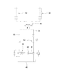
水圧シリンダ30、70の水圧回路を図10に基づき説明する。
40は水タンク、41はポンプ、42はポンプ駆動用モータである。ポンプ41の吐出管は切換弁45を介して、水圧シリンダ30と水圧シリンダ70に選択的に接続される。
The hydraulic circuit of the
40 is a water tank, 41 is a pump, and 42 is a pump drive motor. The discharge pipe of the
水圧シリンダ30、70には供給管51と排出管52が接続されている。供給管51には、逆止弁53が介装されている。この逆止弁53は供給が順方向であり、逆流を阻止するものである。
排出管52には、電磁開閉弁54が介装されている。電磁開閉弁54を閉にして水圧を供給すれば、水圧シリンダ30、70は伸長し、電磁開閉弁54を開にすれば、水圧シリンダ30、70は負荷と自重で収縮する。
A
An electromagnetic opening / closing
水圧シリンダ30の動作と水圧シリンダ70の動作の切替えは、方向切換弁45で行う。方向切換弁45をI位置にすれば水圧シリンダ30が動作し、方向切換弁45をII位置にすれば水圧シリンダ70が動作する。
The operation of the
(使用上の利点)
本発明では、昇降手段2は横移動手段1によって水平移動されるため、従来の水平回動させるものに比べてモーメントが小さく、低圧での昇降動作が可能となる。しかも、水圧シリンダ30、70の水圧回路は閉回路でよいので、使用する水量は少量でよい。このため、水圧ユニットを小型化することができる。
(Usage advantages)
In the present invention, the lifting / lowering means 2 is horizontally moved by the lateral movement means 1, so that the moment is smaller than that of the conventional horizontally rotating means, and the lifting / lowering operation at a low pressure is possible. Moreover, since the hydraulic circuit of the
水圧シリンダ30、70の駆動用モータの電源は電池である。このため、停電時でも水圧シリンダ30、70を駆動することができるので好ましい。また、電池式とすることによって、従来の交流電源を使用する場合に比べて、漏電による感電のおそれがなく、安全性の向上も図られる。
The power source of the drive motor for the
水圧シリンダ30、70の使用水量は少なくてよいので、水タンク40は、椅子搬出入機D用が3リットル位と浴槽昇降機C用が1リットル位のものを合わせて4リットル位で足りる。タンクの個数は1個でも2個でもよい。また、ポンプの吐出能力を小さくしてよいので、ポンプ41やポンプ駆動用モータ42は小型でよく、電池も24V程度の小容量のものでよい。
そして、これらを一体にまとめた水圧駆動ユニット50はコンパクトであるので、図7に示すように、機枠上の空スペース等に設置する事が可能である。
Since the amount of water used by the
And since the
(入浴装置Aの使用方法)
本実施形態に係る入浴装置Aによると、要介護者の入浴を寝浴、座浴両方とも安全かつ容易にし得る。
(How to use bathing apparatus A)
According to the bathing apparatus A according to the present embodiment, bathing by a care recipient can be both safe and easy for both sleeping and sitting.
(寝浴の方法)
図1および図12に示すように、浴槽Bの長辺縁b2にストレッチャーEを近接させて、浴槽昇降機Cで浴槽Bを上昇させると、ストレッチャーE上に仰臥している要介護者を湯舟につけることができる。
入浴が終れば、浴槽Bを下降させ、ストレッチャーEを退避させればよい。
(Method of sleeping)
As shown in FIGS. 1 and 12, when the stretcher E is brought close to the long side edge b <b> 2 of the bathtub B and the bathtub B is raised by the bathtub elevator C, the care recipient who is supine on the stretcher E is shown. Can be attached to a bath.
When bathing is completed, the bathtub B is lowered and the stretcher E is retracted.
(座浴の方法)
図13に示すように、要介護者を着座させる椅子Fを用い、椅子Fの背面側を昇降手段2の前面に向けて配置し、昇降手段2が備える椅子係着部7に椅子Fを係着する。そして、昇降手段2によって椅子Fを上昇させる。
(How to sit down)
As shown in FIG. 13, a chair F on which a care recipient is seated is used, the back side of the chair F is arranged toward the front surface of the elevating
椅子Fが上昇したら、その状態のままで横移動手段1によって椅子Fを水平方向に横移動させる。つまり、図13に示すように、使用位置Uへ水平移動させる。
最後に、昇降手段2によって椅子Fを降下させることにより、椅子Fに着座したままの要介護者を簡単に入浴させることができる。
When the chair F rises, the chair F is moved horizontally in the horizontal direction by the lateral movement means 1 in that state. That is, as shown in FIG.
Finally, by lowering the chair F by the lifting / lowering means 2, the care recipient who is sitting on the chair F can easily take a bath.
本実施形態の入浴装置Aによると、浴槽昇降機Cを使えば、浴槽Bを寝浴用ストレッチャーE上の入浴者を入浴させうる高位置まで上昇させ、かつ寝浴用ストレッチャーEを進入退避させることが可能な低位置まで下降させうる。また、搬出入機Dを使えば、人が座った座浴用椅子Fを浴槽内へ搬入したり浴槽外へ搬出することができる。このため、寝浴用ストレッチャーEに仰臥した入浴者および座浴用椅子Fに座った入浴者の両方とも入浴可能とすることができる。 According to the bathing apparatus A of this embodiment, if the bathtub elevator C is used, the bathtub B is raised to a high position where a bather on the sleeping stretcher E can take a bath, and the sleeping bath stretcher E enters and retreats. Can be lowered to the lowest possible position. Moreover, if the loading / unloading machine D is used, the sitting chair F in which the person sat down can be carried in in a bathtub or carried out of a bathtub. For this reason, both the bather who lies on the stretcher E for sleeping and the bather who sits on the chair F for sitting can be bathed.
本発明の入浴装置は、介護施設や病院などの施設において好適であるが、一般家庭の浴室にも設置できる。 The bathing apparatus of the present invention is suitable for use in facilities such as nursing care facilities and hospitals, but can also be installed in bathrooms of ordinary households.
A 入浴装置
B 浴槽
C 浴槽昇降機
D 椅子搬出入機
1 横移動手段
2 昇降手段
3 基台
7 椅子係着部
10 ガイド機構
11 基端フレーム
12 中間フレーム
13 先端フレーム
15 ローラ
20 縦ガイド機構
21 下段フレーム
22 上段フレーム
23 中間フレーム
30 水圧シリンダ
40 水タンク
41 ポンプ
42 ポンプ駆動用モータ
45 切換弁
50 水圧駆動ユニット
51 供給管
52 排出管
53 逆止弁
54 電磁開閉弁
61 下フレーム
62 上フレーム
63 パンタグラフ機構
64 第1リンク
65 第2リンク
70 水圧シリンダ
71 シリンダ部
72 ロッド
DESCRIPTION OF SYMBOLS A Bathing apparatus B Bathtub C Bathtub elevator D Chair taking in / out
Claims (2)
寝浴用の長尺の浴槽と、
前記寝浴用ストレッチャーを前記浴槽の長辺側縁に接近させた状態で、該浴槽を寝浴用ストレッチャー上の入浴者を入浴させうる高位置まで上昇させ、かつ該寝浴用ストレッチャーを進入退避させることが可能な低位置まで下降させうる浴槽昇降機と、
前記浴槽の短辺側縁の外方に設置された、座浴用椅子を搬入搬出する椅子搬出入機と、
前記椅子搬出入機が、基台と、
前記基台上に設けられ、前記浴槽に対して水平方向に移動可能な横移動手段と、
前記横移動手段上に設けられ、前記浴槽に対して上下方向に移動可能な昇降手段と、
前記昇降手段に取付けられた座浴用椅子を着脱自在に係着する椅子係着部とを備えており、
前記横移動手段が、横フレーム機構と該横フレーム機構を作動させる水圧シリンダと前記横フレーム機構の作動をガイドする横ガイド機構とからなり、
前記横フレーム機構は、基台上に取付けられた基端フレームと、該基端フレームに対し横移動自在な中間フレームと、該中間フレームに対して横移動自在な先端フレームとからなり、
前記横ガイド機構は、前記中間フレームに取付けられたガイドバーが、前記基端フレームに取付けられたガイドローラと前記先端フレームに取付けられたガイドローラで挟まれており、前記先端フレームは前記基端フレームに取付けられた固定ローラでガイドされるガイド構造であり、
前記昇降手段が縦フレーム機構と該縦フレーム機構を作動させる水圧シリンダと前記縦フレーム機構の作動をガイドする縦ガイド機構とからなり、
前記縦フレーム機構は、下段フレームと該下段フレームに対して昇降自在な上段フレームとからなる
ことを特徴とする寝浴座浴両用入浴装置。 A bathing device that allows both a bather lying on a sleeping stretcher and a bather sitting on a sitting chair to take a bath,
A long bathtub for sleeping,
With the sleeping stretcher close to the long side edge of the bathtub, the bathtub is raised to a high position where the bather on the sleeping stretcher can take a bath, and the sleeping stretcher enters and retracts. A bathtub elevator that can be lowered to a low position that can be
A chair loading / unloading machine for loading and unloading a sitting chair, installed outside the short side edge of the bathtub ;
The chair carry-in / out machine has a base,
A lateral movement means provided on the base and movable in a horizontal direction with respect to the bathtub;
Elevating means provided on the lateral movement means and movable in the vertical direction with respect to the bathtub;
A chair engaging part for detachably attaching a sitting chair attached to the elevating means,
The lateral movement means includes a lateral frame mechanism, a hydraulic cylinder that operates the lateral frame mechanism, and a lateral guide mechanism that guides the operation of the lateral frame mechanism.
The horizontal frame mechanism is composed of a base end frame mounted on a base, an intermediate frame movable laterally with respect to the base end frame, and a distal end frame movable laterally with respect to the intermediate frame,
In the lateral guide mechanism, a guide bar attached to the intermediate frame is sandwiched between a guide roller attached to the proximal end frame and a guide roller attached to the distal end frame. It is a guide structure guided by a fixed roller attached to the frame,
The elevating means comprises a vertical frame mechanism, a hydraulic cylinder that operates the vertical frame mechanism, and a vertical guide mechanism that guides the operation of the vertical frame mechanism,
The bathing apparatus for both sitting and sitting baths , wherein the vertical frame mechanism includes a lower frame and an upper frame that is movable up and down with respect to the lower frame .
前記水圧シリンダの駆動源が電池である
ことを特徴とする請求項1記載の寝浴座浴両用入浴装置。 The vertical guide mechanism is a guide roller attached to the lower frame, and has a guide structure that guides with a guide bar attached to the upper frame,
Neyoku sitz bath dual bathing apparatus according to claim 1, wherein the driving source of the hydraulic cylinder is characterized in that it is a battery.
Priority Applications (1)
| Application Number | Priority Date | Filing Date | Title |
|---|---|---|---|
| JP2016108513A JP6232103B1 (en) | 2016-05-31 | 2016-05-31 | Bathing bath for both baths |
Applications Claiming Priority (1)
| Application Number | Priority Date | Filing Date | Title |
|---|---|---|---|
| JP2016108513A JP6232103B1 (en) | 2016-05-31 | 2016-05-31 | Bathing bath for both baths |
Publications (2)
| Publication Number | Publication Date |
|---|---|
| JP6232103B1 true JP6232103B1 (en) | 2017-11-15 |
| JP2017213146A JP2017213146A (en) | 2017-12-07 |
Family
ID=60321136
Family Applications (1)
| Application Number | Title | Priority Date | Filing Date |
|---|---|---|---|
| JP2016108513A Expired - Fee Related JP6232103B1 (en) | 2016-05-31 | 2016-05-31 | Bathing bath for both baths |
Country Status (1)
| Country | Link |
|---|---|
| JP (1) | JP6232103B1 (en) |
Family Cites Families (3)
| Publication number | Priority date | Publication date | Assignee | Title |
|---|---|---|---|---|
| AU521977B2 (en) * | 1977-11-09 | 1982-05-13 | Wright, H.S. | Bathing or shower apparatus |
| JP2002119569A (en) * | 2000-10-18 | 2002-04-23 | Og Giken Co Ltd | Improved type nursing care device |
| JP5963802B2 (en) * | 2014-05-07 | 2016-08-03 | 株式会社Adsムラカミ | Bathing equipment |
-
2016
- 2016-05-31 JP JP2016108513A patent/JP6232103B1/en not_active Expired - Fee Related
Also Published As
| Publication number | Publication date |
|---|---|
| JP2017213146A (en) | 2017-12-07 |
Similar Documents
| Publication | Publication Date | Title |
|---|---|---|
| KR102269093B1 (en) | wheelchair for easy getting on and off | |
| EP3718450A1 (en) | Apparatus for assisting toilet user in standing up | |
| TW200417363A (en) | Fold-up wheelchair and elevating apparatus of the same | |
| JP6232103B1 (en) | Bathing bath for both baths | |
| JP2005204704A (en) | Special bathing system and wheelchair / stretcher | |
| JPH019561Y2 (en) | ||
| JP5963802B2 (en) | Bathing equipment | |
| JP5946898B1 (en) | Bathing equipment | |
| JP6859005B1 (en) | Transfer nursing robot with fixed sitting posture | |
| JP5823886B2 (en) | Bathtub and open / close bathtub | |
| JP2887136B1 (en) | Movement aid | |
| KR102830145B1 (en) | Bathing Device For Preventing Falls Linked To Bed | |
| KR200410118Y1 (en) | Simple mobile bath vehicle for the handicapped person | |
| JPH067713Y2 (en) | Lifting bath equipment | |
| JP3223492U (en) | Elevator | |
| JP3023285B2 (en) | Lift type bathing equipment | |
| JP5938231B2 (en) | Bathtub lift mechanism | |
| JP2003070668A (en) | Bathroom structure | |
| JP2004008678A (en) | Sliding chair system for care | |
| JP2016041159A (en) | Bath apparatus | |
| JP2001087336A (en) | Bathtub for nursing | |
| JP3097276U (en) | Toilet seat lifting device for chair-type toilet | |
| CN115429576A (en) | An electric nursing bed with electric lifting guardrail and toilet seat function | |
| JP5823887B2 (en) | Opening and closing bathtub transfer mechanism | |
| JPH0240981Y2 (en) |
Legal Events
| Date | Code | Title | Description |
|---|---|---|---|
| TRDD | Decision of grant or rejection written | ||
| A01 | Written decision to grant a patent or to grant a registration (utility model) |
Free format text: JAPANESE INTERMEDIATE CODE: A01 Effective date: 20171010 |
|
| A61 | First payment of annual fees (during grant procedure) |
Free format text: JAPANESE INTERMEDIATE CODE: A61 Effective date: 20171020 |
|
| R150 | Certificate of patent or registration of utility model |
Ref document number: 6232103 Country of ref document: JP Free format text: JAPANESE INTERMEDIATE CODE: R150 |
|
| R250 | Receipt of annual fees |
Free format text: JAPANESE INTERMEDIATE CODE: R250 |
|
| R250 | Receipt of annual fees |
Free format text: JAPANESE INTERMEDIATE CODE: R250 |
|
| LAPS | Cancellation because of no payment of annual fees |