JP6232051B2 - Nuclear steam supply system and method - Google Patents
Nuclear steam supply system and method Download PDFInfo
- Publication number
- JP6232051B2 JP6232051B2 JP2015509152A JP2015509152A JP6232051B2 JP 6232051 B2 JP6232051 B2 JP 6232051B2 JP 2015509152 A JP2015509152 A JP 2015509152A JP 2015509152 A JP2015509152 A JP 2015509152A JP 6232051 B2 JP6232051 B2 JP 6232051B2
- Authority
- JP
- Japan
- Prior art keywords
- vessel
- steam
- primary coolant
- reactor
- steam generation
- Prior art date
- Legal status (The legal status is an assumption and is not a legal conclusion. Google has not performed a legal analysis and makes no representation as to the accuracy of the status listed.)
- Expired - Fee Related
Links
Images


Classifications
-
- G—PHYSICS
- G21—NUCLEAR PHYSICS; NUCLEAR ENGINEERING
- G21C—NUCLEAR REACTORS
- G21C15/00—Cooling arrangements within the pressure vessel containing the core; Selection of specific coolants
- G21C15/24—Promoting flow of the coolant
-
- G—PHYSICS
- G21—NUCLEAR PHYSICS; NUCLEAR ENGINEERING
- G21C—NUCLEAR REACTORS
- G21C15/00—Cooling arrangements within the pressure vessel containing the core; Selection of specific coolants
- G21C15/24—Promoting flow of the coolant
- G21C15/26—Promoting flow of the coolant by convection, e.g. using chimneys, using divergent channels
-
- G—PHYSICS
- G21—NUCLEAR PHYSICS; NUCLEAR ENGINEERING
- G21D—NUCLEAR POWER PLANT
- G21D1/00—Details of nuclear power plant
- G21D1/006—Details of nuclear power plant primary side of steam generators
-
- Y—GENERAL TAGGING OF NEW TECHNOLOGICAL DEVELOPMENTS; GENERAL TAGGING OF CROSS-SECTIONAL TECHNOLOGIES SPANNING OVER SEVERAL SECTIONS OF THE IPC; TECHNICAL SUBJECTS COVERED BY FORMER USPC CROSS-REFERENCE ART COLLECTIONS [XRACs] AND DIGESTS
- Y02—TECHNOLOGIES OR APPLICATIONS FOR MITIGATION OR ADAPTATION AGAINST CLIMATE CHANGE
- Y02E—REDUCTION OF GREENHOUSE GAS [GHG] EMISSIONS, RELATED TO ENERGY GENERATION, TRANSMISSION OR DISTRIBUTION
- Y02E30/00—Energy generation of nuclear origin
- Y02E30/30—Nuclear fission reactors
Landscapes
- Physics & Mathematics (AREA)
- Engineering & Computer Science (AREA)
- Plasma & Fusion (AREA)
- General Engineering & Computer Science (AREA)
- High Energy & Nuclear Physics (AREA)
- Heat-Exchange Devices With Radiators And Conduit Assemblies (AREA)
- Structure Of Emergency Protection For Nuclear Reactors (AREA)
Description
関連出願の相互参照
本願は、2012年4月25日出願の米国特許仮出願第61/638,257号の優先権を主張し、その内容全体を参照によって本書に援用する。
本発明は原子力蒸気供給システムに関し、さらに詳しくは、自然重力駆動型冷却材流動循環システムを有する小型モジュール式原子炉のための蒸気供給システムに関する。
This application claims priority to US Provisional Application No. 61 / 638,257, filed Apr. 25, 2012, the entire contents of which are hereby incorporated by reference.
The present invention relates to a nuclear steam supply system, and more particularly to a steam supply system for a small modular reactor having a natural gravity driven coolant flow circulation system.
原子力発電施設用の加圧水型原子炉(PWR)は、原子炉の炉心を冷却するため、および二次冷却材を加熱して、ランキン発電サイクル用の作動流体にすることのできる蒸気を発生させるための両方に、一次冷却材の揚水循環および自然循環の両方を利用している。既存の自然循環PWRは、熱交換装置が原子炉圧力容器と一体化され、その中に配置されるという欠点がある。そのような配置構成は熱交換装置の修理および/または保守点検を難しくするだけでなく、装置を腐食条件にさらすことにもなり、結果的に複雑さを増大させ、原子炉圧力容器への貫通部の数を潜在的に増加させる。加えて、熱交換装置を原子炉圧力容器内に配置することは、原子炉容器の放射性の高い構成部品に近接して熱交換装置を修理するために作業員が受ける放射能レベルに関して問題が生じる。この種の流動循環を利用するシステムで自然循環を達成するために、熱交換器は原子炉容器内に配置すべきであるというのが一般的な見解でもあった。 Pressurized water reactors (PWRs) for nuclear power generation facilities to cool the reactor core and to generate steam that can heat the secondary coolant and make it a working fluid for the Rankine power cycle Both of them use both pumping circulation and natural circulation of the primary coolant. The existing natural circulation PWR has the disadvantage that the heat exchange device is integrated with the reactor pressure vessel and placed therein. Such an arrangement not only makes repair and / or maintenance of the heat exchange device difficult, but also exposes the device to corrosive conditions, resulting in increased complexity and penetration into the reactor pressure vessel. Potentially increasing the number of parts. In addition, placing the heat exchange device within the reactor pressure vessel creates a problem with the level of radioactivity experienced by workers to repair the heat exchange device in close proximity to the highly radioactive components of the reactor vessel. . The general view was that the heat exchanger should be placed in a reactor vessel to achieve natural circulation in a system that utilizes this type of fluid circulation.
改善された原子力蒸気供給システムが望まれている。 An improved nuclear steam supply system is desired.
本発明は、上述した既存の配置構成の欠点を克服する、改善された原子力供給システムを提供する。 The present invention provides an improved nuclear power supply system that overcomes the disadvantages of the existing arrangements described above.
本発明の一実施形態では、自然重力駆動冷却材循環による原子力蒸気供給システムは、内部空洞を形成するシェルを備えた縦方向に細長い原子炉容器と、内部空洞内に配置された核燃料を備えた原子炉炉心と、シェルおよび垂直積層関係に配置された複数の熱交換器部を備えた蒸気発生容器であって、蒸気発生容器のシェルが原子炉容器のシェルとは別個に形成され、流体継手を介して原子炉容器のシェルと一体に流体接続された、蒸気発生容器と、原子炉容器と蒸気発生容器との間に形成された閉ループ一次冷却材システムであって、原子炉圧力容器中を流れて原子炉炉心を冷却すると共に、蒸気発生容器中を流れて熱を、蒸気発生容器中を流れる二次冷却材に伝達する、一次冷却材を有する一次冷却材システムとを含む。一次冷却材システムは、原子炉容器および蒸気発生容器中を流れる一次冷却材の重力駆動循環を誘発するように構成される。二次冷却材は蒸気発生容器の熱交換器部の各々の中を垂直方向に流れ、相を液体から蒸気に変化させる。したがって、一実施形態では、一次冷却材システムはポンプを含まない。原子炉炉心の稼働は、原子炉容器と蒸気発生容器との間の閉ループ一次冷却材システムの一次冷却材の自然循環を引き起こすのに充分な程度まで、一次冷却材を加熱させる。 In one embodiment of the invention, a nuclear steam supply system with natural gravity driven coolant circulation comprises a vertically elongated reactor vessel with a shell forming an internal cavity, and a nuclear fuel disposed within the internal cavity. A steam generation vessel comprising a nuclear reactor core and a plurality of heat exchanger portions arranged in a shell and a vertically stacked relationship, wherein the shell of the steam generation vessel is formed separately from the shell of the reactor vessel, and the fluid coupling And a closed loop primary coolant system formed between the reactor vessel and the steam generation vessel, which is fluidly connected to the reactor vessel shell through the reactor pressure vessel. And a primary coolant system having a primary coolant that flows to cool the reactor core and that transfers heat to the secondary coolant that flows through the steam generation vessel. The primary coolant system is configured to induce a gravity driven circulation of the primary coolant flowing through the reactor vessel and the steam generating vessel. The secondary coolant flows vertically through each of the heat exchanger sections of the steam generating vessel, changing the phase from liquid to steam. Thus, in one embodiment, the primary coolant system does not include a pump. Operation of the reactor core heats the primary coolant to a degree sufficient to cause a natural circulation of the primary coolant in the closed loop primary coolant system between the reactor vessel and the steam generating vessel.
別の実施形態では、自然重力駆動冷却材循環による原子力蒸気供給システムは、第1垂直軸線を有し、かつ内部空洞を形成するシェルを備えた、縦方向に細長い原子炉容器と、流動流体を導通させるために原子炉容器の空洞内に配置された垂直ライザおよびダウンカマであって、相互に流体連通している垂直ライザおよびダウンカマと、原子炉容器の内部空洞内に配置された核燃料を備えた原子炉炉心と、第2垂直軸線と、垂直積層関係に流体接続された複数の熱交換器部を含む円筒形シェルとを有する、縦方向に細長い蒸気発生容器であって、蒸気発生容器のシェルが原子炉容器のシェルとは別個に形成され、流体継手を介して原子炉容器のシェルと一体に流体接続された、蒸気発生容器と、原子炉炉心による加熱のために一次冷却材が原子炉容器のダウンカマおよび垂直ライザを流れ、一次冷却材がさらに蒸気発生容器の熱交換器部を流れて熱を、蒸気発生容器を流れる二次冷却材に伝達する、重力駆動閉流動ループを有する原子炉一次冷却材システムとを含む。二次冷却材は蒸気発生容器の熱交換器部を垂直に流過し、相を液体から蒸気に変化させる。原子炉容器の第1垂直軸線は、蒸気発生容器の第2垂直軸線から側方に偏位する。コンテナシステムを用いて放射性廃棄物を貯蔵するための例示的方法を提供する。方法は、原子炉容器に配置された原子力原子炉炉心で液体一次冷却材を加熱するステップと、加熱された一次冷却材を、原子炉炉心に流体接続された垂直ライザ内で第1垂直方向に原子炉容器中を上方に流過させるステップと、加熱された一次冷却材を原子炉容器の頂部から出口を介して排出するステップと、加熱された一次冷却材を蒸気発生容器の底部で入口を介して受容するステップと、加熱された一次冷却材を垂直ライザ管内で第1垂直方向に蒸気発生容器中を上方に流過させるステップと、加熱された一次冷却材を容器の頂部で受容するステップと、加熱された一次冷却材の流動の方向を第1垂直方向の上向きから第2垂直方向の下向きに上下反転させるステップと、加熱された一次冷却材を蒸気発生容器中を第2垂直方向に下方に流過させ、そこで一次冷却材を冷却させるステップと、冷却された一次冷却材を原子炉容器に還流させるステップと、原子炉容器における加熱ステップを繰り返すステップとを含み、原子炉容器および蒸気発生容器中の一次冷却材の流動は閉循環流動ループを形成する。一実施形態では、方法はさらに、二次冷却材を一次冷却材の第1および第2垂直方向と平行に上方に蒸気発生容器中を流過させるステップを含む。一実施形態では、方法はさらに、二次冷却材が蒸気発生容器の底部に飽和液体として流入するステップと、蒸気発生容器の頂部から過熱蒸気として流出するステップとを含む。 In another embodiment, a nuclear steam supply system with natural gravity driven coolant circulation includes a longitudinally elongated reactor vessel having a first vertical axis and a shell forming an internal cavity, and a flowing fluid. A vertical riser and downcomer disposed in a reactor vessel cavity for electrical conduction, comprising a vertical riser and downcomer in fluid communication with each other, and a nuclear fuel disposed in an interior cavity of the reactor vessel A longitudinally elongated steam generating vessel having a nuclear reactor core, a second vertical axis, and a cylindrical shell including a plurality of heat exchanger portions fluidly connected in a vertical stacking relationship, the steam generating vessel shell Is formed separately from the reactor vessel shell and fluidly connected to the reactor vessel shell through a fluid coupling, and the primary coolant is heated for heating by the reactor core. An atom with a gravity-driven closed flow loop that flows through the downcomer and vertical riser of the furnace vessel, where the primary coolant further flows through the heat exchanger section of the steam generation vessel and transfers heat to the secondary coolant flowing through the steam generation vessel Furnace primary coolant system. The secondary coolant flows vertically through the heat exchanger section of the steam generating vessel and changes the phase from liquid to steam. The first vertical axis of the reactor vessel is offset laterally from the second vertical axis of the steam generating vessel. An exemplary method for storing radioactive waste using a container system is provided. The method includes heating a liquid primary coolant in a nuclear reactor core disposed in a reactor vessel, and the heated primary coolant in a first vertical direction in a vertical riser fluidly connected to the reactor core. Flowing through the reactor vessel upward; discharging the heated primary coolant from the top of the reactor vessel through the outlet; and passing the heated primary coolant through the inlet at the bottom of the steam generating vessel. Receiving the heated primary coolant through the steam generator vessel in a first vertical direction in the vertical riser tube, and receiving the heated primary coolant at the top of the vessel. Reversing the direction of the flow of the heated primary coolant from the upward in the first vertical direction to the downward in the second vertical direction; and passing the heated primary coolant in the steam generating container in the second vertical direction. Down And the step of cooling the primary coolant therethrough, the step of returning the cooled primary coolant to the reactor vessel, and the step of repeating the heating step in the reactor vessel, The primary coolant flow forms a closed circulation flow loop. In one embodiment, the method further includes flowing the secondary coolant through the steam generation vessel upward parallel to the first and second vertical directions of the primary coolant. In one embodiment, the method further includes the steps of secondary coolant flowing into the bottom of the steam generation vessel as a saturated liquid and outflowing as superheated steam from the top of the steam generation vessel.
本発明の利点および態様は以下を含む。 Advantages and aspects of the present invention include:
地下深部の炉心:原子炉の炉心は、大型PWRおよびBWR原子炉で原子炉の完全性の維持における有効性が数十年にわたって実証されたASME規格の材料から作られた厚壁の原子炉容器(RV)内で地下深部に存在する。原子炉冷却材によって湿潤される全ての表面は、RVにおける主要な腐食源およびクラッドの蓄積を排除するステンレス鋼またはインコネルから作られる。 Deep underground core: The core of the reactor is a thick-walled reactor vessel made of ASME standard material that has been proven in large PWR and BWR reactors for decades in the effectiveness of maintaining the integrity of the reactor. It exists in the deep underground in (RV). All surfaces wetted by the reactor coolant are made from stainless steel or Inconel, which eliminates major corrosion sources and cladding buildup in RV.
原子炉冷却材の重力駆動循環:本開示に係る原子力蒸気供給システムは、原子炉冷却材が炉心を循環するためにいかなる能動部品(すなわち原子炉冷却材ポンプ)にも依存しない。代わりに、RV、蒸気発生器の熱交換器、およびその他の各種機器中の原子炉冷却材の流動は、一次ループの高温および低温セグメント間の流水の密度差によって生成される圧力水頭によって生じる。原動力としての重力の信頼性は、その本質的安全性を裏付ける。原子炉冷却材の移動にポンプ、弁、またはいかなる種類の運動機械も不要である。 Gravity-driven circulation of reactor coolant: The nuclear steam supply system according to the present disclosure does not rely on any active components (ie, reactor coolant pump) for the reactor coolant to circulate through the core. Instead, the flow of reactor coolant in RVs, steam generator heat exchangers, and various other equipment is caused by pressure heads generated by the density difference of the flowing water between the hot and cold segments of the primary loop. The reliability of gravity as a driving force supports its intrinsic safety. No pumps, valves, or any kind of exercise machine are needed to move the reactor coolant.
自力起動が可能(外部電源への無依存):外部電源は、原子力蒸気供給システムを起動または停止させるのに必須ではない。作動停止中の原子炉残留熱の排除もまた重力駆動循環によって引き起こされる。こうして、原子力発電所の主要な関心事である、現場の緊急停止電力供給の必要性は排除される。実際、原子力蒸気供給システムは、正常および事故の両方の条件下でその稼働要件を満たすために、重力を(そして重力だけを)原動力として使用する。 Self-starting is possible (independent of external power supply): External power supply is not essential for starting or stopping the nuclear steam supply system. The elimination of reactor residual heat during shutdown is also caused by gravity driven circulation. This eliminates the need for an on-site emergency shutdown power supply, which is a major concern for nuclear power plants. In fact, the nuclear steam supply system uses gravity (and gravity alone) as the driving force to meet its operational requirements under both normal and accident conditions.
原子炉炉心の上および周囲における大量貯水の確保:本発明の原子力蒸気供給システムの原子炉容器(RV)はその頂部以外に貫通部を持たず、それは、全ての正常な熱排除経路が失われる仮説的な想定事象下でさえも、炉心が大量の貯水中に浸漬され続けることを意味する。 Ensuring a large amount of water storage on and around the reactor core: The nuclear reactor vessel (RV) of the nuclear steam supply system of the present invention has no penetrations beyond its top, which loses all normal heat rejection paths This means that even under hypothetical hypothetical events, the core continues to be immersed in a large amount of stored water.
原子炉容器(RV)における大きい貫通部が無い:RVにおける全ての貫通部はRVの頂部に配置され、サイズは小さい。原子炉冷却材システムにおける大きい配管の不在は、「大破断」冷却材喪失事故(LOCA)事象の潜在的可能性を排除する。 There are no large penetrations in the reactor vessel (RV): all penetrations in the RV are located on top of the RV and are small in size. The absence of large piping in the reactor coolant system eliminates the potential for a “large break” loss of coolant accident (LOCA) event.
全ての重要部品への容易なアクセス性:いわゆる「一体型」原子炉システムとは対照的に、蒸気発生器および制御棒駆動システムは、RVの外側の容易にアクセスできる高さに配置され、予防保守および修理を簡便に実行される作業にする。蒸気発生器は一部の実施形態では、予熱器、蒸気発生器、および上に加圧器が搭載された過熱器を含む、単一ループから構成される。ループ内の熱交換器、すなわち予熱器、蒸気発生器、および過熱器は、管に簡便にアクセスしかつ差し込むために、熱交換器管板および/または管束へのアクセスをもたらす、適切に配置されたマンホールのような設計上の特徴を組み込んでいる。熱交換装置を原子力蒸気供給システムにおける原子炉空洞の苛酷な環境の外側に配置する決定は、過去30年にわたるPWR蒸気発生器の低い信頼性、およびそれらを交換するために業界によって負担される莫大な費用によって特徴付けられてきた。 Easy access to all critical components: In contrast to the so-called “integrated” reactor system, the steam generator and control rod drive system are located at an easily accessible height outside the RV and prevent Make maintenance and repair work easy to perform. The steam generator, in some embodiments, consists of a single loop that includes a preheater, a steam generator, and a superheater with a pressurizer mounted thereon. The heat exchangers in the loop, i.e., preheater, steam generator, and superheater, are suitably arranged to provide access to the heat exchanger tubesheet and / or tube bundle for convenient access and plugging into the tube. It incorporates design features such as manholes. The decision to place heat exchange equipment outside the harsh environment of the reactor cavity in the nuclear steam supply system has made the PWR steam generators less reliable over the past 30 years and the huge burden imposed by the industry to replace them Has been characterized by significant costs.
RVフランジは、RV円筒の外周を越えるその突出を最小化するリバースジョイントを特徴とする。この設計革新は、スタックをRVノズルに直接接続すること、すなわちgorging to forging接続を可能にし、それらの間の配管を排除する。この設計上の特徴は、大管破断LOCAの危険性を排除する。 The RV flange features a reverse joint that minimizes its protrusion beyond the outer periphery of the RV cylinder. This design innovation allows a stack to be connected directly to the RV nozzle, ie a gorging to forging connection, eliminating the piping between them. This design feature eliminates the risk of large tube breakage LOCA.
原子炉冷却材としての脱塩水:原子炉冷却材は、温度の上昇によるその強い負の反応性勾配のため、臨界安全性を高める脱塩水である。ホウ酸塩水の除去もまた、一次冷却材中のホウ素レベルを維持および管理するために必要なシステムおよび機器を除去することによって、原子力蒸気供給システム(NSSS)を簡素化する。純水および耐食性一次冷却材ループは、RVにおけるクラッドの蓄積を最小化するのに役立つ。 Demineralized water as reactor coolant: Reactor coolant is demineralized water that increases critical safety due to its strong negative reactivity gradient with increasing temperature. The removal of borate water also simplifies the nuclear steam supply system (NSSS) by removing the systems and equipment necessary to maintain and manage the boron level in the primary coolant. Pure water and corrosion resistant primary coolant loops help minimize clad buildup in the RV.
改善された蒸気サイクルの信頼性:蒸気サイクルの信頼性は、高圧タービンを完全に省くことによって改善される。むしろ、サイクル蒸気は低圧タービンに送られる前に過熱される。ランキン効率の損失は0.5パーセント未満である。電力サイクルの信頼性の向上および簡素化に関する利益はかなり大きい。 Improved steam cycle reliability: Steam cycle reliability is improved by eliminating the high pressure turbine completely. Rather, the cycle steam is superheated before being sent to the low pressure turbine. Rankine efficiency loss is less than 0.5 percent. The benefits associated with improving and simplifying power cycle reliability are substantial.
圧力制御:加圧器は従来の加熱/急冷要素(圧力制御のための水/蒸気)を含む。一連の電熱器が加圧器部に取り付けられ、それは、一次冷却材の一部を沸騰させ、かつ加圧器の頂部のヘッド付近に滞留する蒸気泡を発生させることによって、圧力を増大させるように働く。噴霧塔が加圧器の頂部ヘッド付近に配置され、それは蒸気泡に水を噴霧し、それによって蒸気を凝縮して、蒸気泡を低減させる。蒸気泡のサイズの増大/縮小は、原子炉冷却材システム内の一次冷却材の圧力を増大/低減させるように働く。1つの例示的実施形態では、加圧器によって維持される一次冷却材圧力は、約2,250psiとすることができるが、それに限定されない。 Pressure control: The pressurizer includes conventional heating / quenching elements (water / steam for pressure control). A series of electric heaters are attached to the pressurizer section, which serves to increase the pressure by boiling a portion of the primary coolant and generating vapor bubbles that reside near the head at the top of the pressurizer. . A spray tower is located near the top head of the pressurizer, which sprays water onto the steam bubbles, thereby condensing the steam and reducing the steam bubbles. Increasing / decreasing the size of the steam bubbles serves to increase / decrease the pressure of the primary coolant in the reactor coolant system. In one exemplary embodiment, the primary coolant pressure maintained by the pressurizer can be about 2,250 psi, but is not limited thereto.
代替的実施形態では、窒素式加圧器システムを使用することができる。この実施形態では、加圧器は、加圧器に流体連結された外部高圧窒素タンクから制御された窒素圧を加えることによって、原子炉容器の圧力を制御するように働く。窒素圧制御原子炉は他の型の原子炉で使用されてきており、迅速な応答プロファイルを持ち長年の成功稼働経験を有する。 In an alternative embodiment, a nitrogen pressurizer system can be used. In this embodiment, the pressurizer serves to control the reactor vessel pressure by applying a controlled nitrogen pressure from an external high pressure nitrogen tank fluidly coupled to the pressurizer. Nitrogen pressure controlled reactors have been used in other types of reactors and have a rapid response profile and many years of successful operational experience.
原子炉内の燃料破損の防止:稼働中の全燃料破損の70パーセント以上は、フレッティング(繰返し衝撃による腐食)損傷から発生することが知られており、それはグリッドストラップによる燃料棒の「ピンジング」の結果である。グリッドストラップの振動は、燃料の周囲の乱流のレベルに直接関係する。本発明の原子力蒸気供給システムでは、レイノルズ数は、今日の典型的な稼働中のPWRのレイノルズ数の約20パーセントである。低いレイノルズ数は、燃料棒に対するピンジング作用の緩和(腐食率は衝撃速度の約4.8乗で変化する)、およびしたがってフレッティング損傷率の劇的低下と解釈される。本発明の原子力蒸気供給システムに選択される低い燃焼レベル(現在稼働している原子炉の約60と比較して、(1MTU当たり45GWDの範囲)もまた、燃料被覆材の脆性を改善するのに役立ち、したがって燃料棒の損耗を防止する。 Prevention of fuel failure in the reactor: More than 70 percent of all fuel failure during operation is known to result from fretting damage, which is “pinning” fuel rods by grid straps. Is the result of Grid strap vibration is directly related to the level of turbulence around the fuel. In the nuclear steam delivery system of the present invention, the Reynolds number is about 20 percent of the Reynolds number of today's typical operating PWR. A low Reynolds number is interpreted as a relaxation of the pinning action on the fuel rods (corrosion rate varies by about 4.8th power of impact) and thus a dramatic reduction in fretting damage rate. The low combustion level selected for the nuclear steam supply system of the present invention (in the range of 45 GWD per MTU) compared to about 60 for currently operating reactors also improves fuel brittleness. Useful, thus preventing fuel rod wear.
自己遮蔽の増大:本発明の原子力蒸気供給システム(NSSS)における一次流体の重力駆動循環は、別の顕著な利益をNSSSから生じる放射線量の劇的低減の形で生み出す。これは、炉心の炉水の酸素の中性子衝撃によって生じる窒素(N−16)同位体が、格納容器から発する放射線の大きな原因である高ガンマエネルギ放出N−16同位体を生成するためである。しかし、N−16は半減期がわずか7.4秒であり、それは、一次水が蒸気発生器の頂部まで移動するのに要する時間の4分の1に満たない。したがって、N−16の量は7超の半減期で減少し、それは事実上、極小値まで減少することを意味する。スコーピング計算は、NSSSの蒸気発生器の頂部からの放射線量を同様の大きさの揚水型PWRより3桁以上小さくすることができることを示唆している。したがって、放射線の遮蔽のために本発明のNSSS用の厚いコンクリートの格納容器を建造する必要が無い。鉄筋コンクリートの格納容器を現場で建造する代わりに、航空機の衝突に耐えることのできる、工場で製作された鋼製格納容器が配置され、それはより適切であり、かつより経済的である。 Increased self-shielding: Gravity-driven circulation of the primary fluid in the nuclear steam supply system (NSSS) of the present invention creates another significant benefit in the form of a dramatic reduction in radiation dose resulting from NSSS. This is because the nitrogen (N-16) isotope produced by the neutron bombardment of oxygen in the reactor core water produces a high gamma energy emitting N-16 isotope that is a major source of radiation emanating from the containment vessel. However, N-16 has a half-life of only 7.4 seconds, which is less than a quarter of the time it takes for the primary water to travel to the top of the steam generator. Thus, the amount of N-16 decreases with a half-life greater than 7, which means that it effectively decreases to a local minimum. Scoping calculations suggest that the radiation dose from the top of the NSSS steam generator can be more than three orders of magnitude smaller than similarly sized pumped PWRs. Therefore, it is not necessary to build a thick concrete containment vessel for NSSS of the present invention to shield radiation. Instead of building a reinforced concrete containment in the field, a factory-made steel containment that can withstand aircraft crashes is deployed, which is more appropriate and more economical.
本発明の例示的実施形態の特徴を、以下の図面に関連して説明する。これらの図において、類似の要素には類似の記号が付けられている。 Features of exemplary embodiments of the invention are described with reference to the following drawings. In these figures, similar elements are labeled with similar symbols.
全ての図面は概略図であって、必ずしも正確な縮尺ではない。 All drawings are schematic and are not necessarily to scale.
本発明の特徴および利点について、本明細書で例示的実施形態を参照することによって例証し説明する。例示的実施形態のこの説明は、明細書全体の一部とみなされる添付の図面に関連して読むように意図されている。本書に開示する実施形態の説明において、方向または向きの言及は単に、説明の便宜を図ることを意図するにすぎず、いかなる形でも本発明の範囲を限定することを意図するものではない。「下方」、「上方」、「水平」、「垂直」、「より上」、「より下」、「上向き」、「下向き」、「頂部」、および「底部」のような相対的用語およびそれらの派生語(例えば「水平に」、「下向きに」、「上向きに」等)は、そのとき説明されているか、あるいは説明している図面に示されている向きを指していると解釈すべきである。これらの相対的用語は、単に説明の便宜を図るものであって、装置を特定の向きに構築または操作することを要求するものではない。「取り付けられた」、「付着された」、「接続された」、「連結された」、「相互接続された」のような用語等は、明示的にそうでないことが記載されない限り、構造物が直接的にまたは介在構造物を介して間接的に相互に固定されまたは取り付けられる関係のみならず、可動または不動の取付け状態または関係をも指す。したがって、開示は明示的に、単独でまたは他の特徴と組み合わせて存在することのできる特徴の一部の可能な非限定的組合せを例証するそのような例示的実施形態に限定されない。 The features and advantages of the invention are illustrated and described herein by reference to exemplary embodiments. This description of the exemplary embodiments is intended to be read in conjunction with the accompanying drawings, which are considered part of the entire specification. In the description of the embodiments disclosed herein, references to directions or orientations are merely intended for convenience of description and are not intended to limit the scope of the invention in any way. Relative terms such as “down”, “up”, “horizontal”, “vertical”, “above”, “below”, “upward”, “downward”, “top”, and “bottom” and those Derivatives of (eg “horizontal”, “downwardly”, “upwardly”, etc.) should be interpreted as referring to the orientation described at the time or shown in the drawings being described It is. These relative terms are merely for convenience of explanation and do not require that the device be constructed or operated in a particular orientation. Terms such as “attached”, “attached”, “connected”, “coupled”, “interconnected”, etc., unless otherwise stated explicitly Refers to not only a relationship that is fixed or attached to each other directly or indirectly via an intervening structure, but also a movable or immovable attachment state or relationship. Accordingly, the disclosure is not explicitly limited to such exemplary embodiments that illustrate some possible non-limiting combinations of features that may exist alone or in combination with other features.
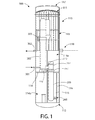
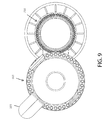
図1〜図6を参照すると、本開示に係る原子力加圧水型原子炉(PWR)のための蒸気供給システムが示されている。熱水力的観点から、システムは、原子炉容器200と、原子炉容器に流体連結された蒸気発生容器300とを一般的に含む蒸気発生器組立体100を含む。蒸気発生容器および原子炉容器は縦方向に細長い別個の構成部品であり、それらは油圧で密結合されているが、容器の間を流れる一次ループ冷却材(すなわち原子炉冷却材)の熱交換を除いては熱的に分離された、それ自体個別の容器である。本書でさらに説明する通り、蒸気発生容器300は一実施形態では、予熱器320と、主蒸気発生器330と、二次冷却材ループを流れる水のような流体を入口301で蒸気発生容器300に流入する液体から出口302で蒸気発生容器から流出する過熱蒸気に変換する過熱器350とを含む。二次冷却材ループの水は、一部の実施形態で電力を生産するためにタービン発電設備を駆動するのに使用される、ランキンサイクル流体とすることができる。
Referring to FIGS. 1-6, a steam supply system for a nuclear pressurized water reactor (PWR) according to the present disclosure is shown. From a hydro-hydraulic point of view, the system includes a
蒸気発生容器300はさらに、一次冷却材流体の所定の圧力を維持する加圧器380を含む。加圧器は、蒸気発生容器300の上に取り付けられた圧力容器であり、蒸気発生器内の一次冷却材圧力の制御を可能にするように動作する液体/気体界面(すなわち一次冷却材の水/不活性ガス)を維持するように設計されている。一実施形態では、図示する通り、加圧器380は蒸気発生容器300の上に直接取り付けることもでき、容器の頂端を油圧で密閉するための容器の一体的な単一の構造部品を形成する。上述した3つの熱交換器および加圧器の集合を「スタック」と呼ぶことがある。
The
図1を参照すると、原子炉容器200および蒸気発生容器300は蒸気発生器封じ込め容器110に格納されている。封じ込め容器110は、頂部111、底部112、およびそれらの間に延びる円筒状側壁113から構成された適切な工場製作鋼製容器とすることができる。一部の実施形態では、封じ込め容器の地表面より上に位置する部分は、航空機の衝突に耐えるのを助けるように延性リブ付き鋼で作製してよい。封じ込め容器110の頂部111の上に間隔を置いて配置されるミサイルシールド117は、封じ込め容器の一部分として、または封じ込め容器110を包囲する別個の封じ込め囲い構造体(図示せず)として設けてよい。水平隔壁114は封じ込め容器を上部114aおよび下部114bに分割する。隔壁114は封じ込め容器内の床を画定する。一実施形態では、図示するように、原子炉容器200の大部分は下部114bに配置することができ、蒸気発生容器300は上部114aに配置することができる。
Referring to FIG. 1, the
様々な実施形態で、封じ込め容器110は、地上に、部分的に地下に、または完全に地下に設置することができる。特定の実施形態では、封じ込め容器110は、原子力燃料原子炉炉心(例えば燃料カートリッジ230)を含む下部114bの少なくとも一部分または全部が地面の下に位置するように、配置することができる。一実施形態では、原子炉容器200全体および蒸気発生容器300の一部分は、最大限の安全のために完全に地下に位置する。封じ込め容器110の円筒状のシェルまたは側壁113は、図1に示すように、封じ込め容器の地上および地下に位置する部分の境界を設けるために、周方向に溶接またはボルト締結されるフランジ継手119によって接合される、上部および下部に水平分割することができる。他の実施形態では、上部および下部はフランジを使用することなく溶接することができる。
In various embodiments, the
一実施形態では、例えば封じ込め容器110は、160MW(メガワット)のモジュール式原子力発電施設の場合、約200フィート以上の代表的高さを有することができるが、それに限定されない。この発電施設の非限定的な代表的直径は約45フィートである。システム構成部品の構成および寸法に応じて、封じ込め容器は任意の適切な高さおよび直径を持つことができる。
In one embodiment, for example, the
封じ込め容器110はさらに、一実施形態では、増強された放射線遮蔽および原子炉炉心用の容易にアクセス可能な冷却材の予備的貯蔵を提供するために冠水した円筒状外接壁包囲体116によって画定される、ウェット原子炉ウェル115を含む。一実施形態では、壁包囲体116は、図示するように原子炉容器200の外周に延びるステンレス鋼の円筒状壁から形成することができる。包囲体116を構築するために、他の適切な材料を使用してよい。ウェット原子炉ウェル115は、封じ込め容器110の下部114bに配置される。下部114bはさらに、包囲体116に隣接して、冠水(すなわち水)使用済み燃料プール118を含むことができる。一実施形態では、図1に示すように、使用済み燃料プール118および壁包囲体116の両方が図1に示すように水平隔壁114の下に配置される。
The
一実施形態では、図1に示すように、壁包囲体116は隔壁114の上に延びることができ、原子炉容器と蒸気発生容器との間の入口/出口ノズル接続は、壁包囲体の貫通によって行うことができる。
In one embodiment, as shown in FIG. 1, the
さらに図1に示すように、原子炉容器200および蒸気発生容器300は両方とも、封じ込め容器110の接地面積および直径を低減するために、図示するように垂直方向に配向することが好ましい。封じ込め容器110は、原子炉容器および蒸気発生容器の両方、ならびに任意の他の装備を格納するのに充分大きい直径を有する。封じ込め容器110は、電力生産用のタービン発電設備を駆動するためにランキンサイクルに関連する第2冷却材ループ流体の流れのための水および蒸気の入口および出口貫通部を除き、完全に格納された蒸気発生器を提供するように、原子炉容器および蒸気発生容器を完全に格納するのに充分大きい高さを有することが好ましい。
As further shown in FIG. 1, both the
図2は、一次冷却材ループ内の一次冷却材(例えば水)の流れまたは循環を示す。一実施形態では、一次冷却材流は、原子炉容器200で加熱され、次いで蒸気発生容器300で、熱がタービン発電(T−G)設備を駆動するランキンサイクルの二次冷却材ループに伝達されるときに冷却されるので、冷却材の温度および対応する密度の変化に依存する重力駆動式である。冷却材の変化する異なる密度(すなわち高温−低密度および低温−高密度)によって生じる圧力水頭は、流れ方向矢印によって示されるように、原子炉容器−蒸気発生容器システム中の流れまたは循環を誘発する。利点は、重力駆動一次冷却材の循環は冷却材ポンプまたは機械類を必要とせず、よって結果的にコスト(資本、運営、および維持)が節減され、システムの電力消費が低減し、よってPWRシステムのエネルギ変換効率が増大することであり、それに加えて本書に記載する他の利点もある。
FIG. 2 illustrates the flow or circulation of the primary coolant (eg, water) within the primary coolant loop. In one embodiment, the primary coolant stream is heated in the
原子炉容器200は、2012年8月3日に出願した本願と同一出願人による米国特許出願第13/577,163号に開示された、重力駆動循環システムを備えた原子炉容器と同様とすることができ、その内容全体を参照によって本書に援用する。
The
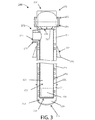
図3を参照すると、1つの非限定実施例における原子炉容器200は、一体的に溶接された半球形底部ヘッド203および取外し可能な半球形頂部ヘッド202を備えた円筒状側壁シェル201から構成された、ASME規格第3章分類1の厚壁筒形圧力容器である。シェル201は、本書に記載する通り、原子炉炉心、原子炉シュラウド、および他の装備を保持するように構成された内部空洞208を画定する。一実施形態では、原子炉容器シェル201の上端部は、頂部ヘッド202に溶接された同様のフランジ205にボルトで締結されたテーパ付きハブフランジ204(当業界で「溶接ネック」フランジとしても知られる)を具備することができる。一実施形態では、頂部ヘッド202は、あらゆる運転モードで高結合性二重ガスケットシールを確立するために予張力を加えた1組の合金ボルト(図示せず)を介して、(円筒状原子炉容器シェルに対しても突合せ溶接される)「頂部フランジ」に固定される。頂部ヘッド202のボルト締結接続は、原子炉炉心のような原子炉容器内部へのアクセスを容易にする。
Referring to FIG. 3, a
2つの相フランジ204、205の間で圧縮される2つの同心状の自己緊塞ガスケット206は、頂部ヘッド202とシェル201との間の接続部における原子炉容器200の漏れ密封性をもたらす。稼働条件下の漏れ密封性は、本書でさらに説明する通り、システムにおける一次冷却材の流体の流れ構成によってもたらされる、フランジ継手の軸対称性加熱によって保証される。頂部ヘッド202は制御棒を挿入するための垂直貫通部207を含み、かつさらに、関連する制御棒駆動体を取り付けるための基礎としても役立つことができ、それらは両方とも描かれておらず、これ以上詳述しないが、当業界では周知である。
Two concentric self-sealing gaskets 206 that are compressed between the two
引き続き図3を参照すると、原子炉容器200は、燃料カートリッジ230によって画定される原子炉炉心を収容する円筒状原子炉シュラウド220を含む。原子炉シュラウド220は、原子炉容器のシェル部を横方向に2つの同心状に配設された空間に分割する。すなわち(1)原子炉シュラウドの外面とシェル201の内面との間に形成され、一次冷却材が原子炉容器に流入するための環状ダウンカマ222を画定する外環221、および(2)原子炉炉心における核分裂によって加熱され、原子炉容器から流出する一次冷却材のためのライザカラム224を画定する通路223である。原子炉シュラウド220は細長く、原子炉容器の垂直軸線VA1に沿って軸線方向に延び、高さを画定し、開口底部225および閉鎖頂部226を含む。一実施形態では、本書でさらに説明する通り、頂部226は、ライザカラム224を上昇流動してきた一次冷却材を蒸気発生容器300に向かわせる、頂部流れ遮断板227によって閉鎖することができる。一実施形態では、原子炉シュラウド220の底部225は、原子炉容器200の底部ヘッド203から垂直方向に離して配置され、底部フロープレナム228を画定する。底部フロープレナム228は環状ダウンカマ222から一次冷却材を捕集し、冷却材の流れを原子炉シュラウド220の開口底部225によって形成されるライザカラム224の入口に向かわせる(例えば図2参照)。
With continued reference to FIG. 3, the
燃料カートリッジ230および原子炉シュラウド220は両方とも、炉心支持構造体(「CSS」)によって支持され、それは一実施形態では、原子炉シュラウドおよび原子炉容器200のシェル201の間に渡され、それらに取り付けられた複数の側方支持部材250を含む。周方向および垂直方向の両方に間隔を置いて配置された適切な数の支持部材が、燃料カートリッジ230および原子炉シュラウド220の総合重量を支持するために必要に応じて設けられる。一実施形態では、原子炉シュラウド220の底部は、シュラウドが垂直軸線方向に(すなわち垂直軸線VA1と平行に)熱的に成長することを不当に束縛することなく可能にするために、原子炉容器200に固定されない。
Both the
原子炉シュラウド220は一実施形態では、ステンレス鋼のような、しかしそれに制限されない耐食性材料から作ることのできる二重壁のシリンダである。原子炉シュラウド220のこの二重壁構成は、それを越える熱の流れを遅らせるよう設計された断熱構造体を形成し、かつ図1〜図3に示すように一実施形態ではシュラウドの底端部に位置することが好ましい燃料カートリッジ230(「炉心」)における核分裂によって加熱された一次冷却材(すなわち水)の上昇流のための平滑な垂直ライザカラム224を形成する。原子炉シュラウド220内の燃料カートリッジ230の上の垂直空間は、相互接続された制御棒セグメントと共に、原子炉の稼働中に流れに誘発される振動からそれらを保護するように働く1組の「非セグメントバフル」を含むこともできる。原子炉シュラウド220は、金属疲労から破損を誘発することがある機械的振動による損傷を防止するために、支持部材250により原子炉容器によって側方に支持される。
The
一実施形態の燃料カートリッジ230は直立燃料アセンブリを包含する単一自律的構造体であり、相対的に深い水のプレナムが燃料カートリッジの下に位置するように、底部ヘッド203の上に間隔を置いて配置された原子炉容器200の領域に配置される。燃料カートリッジ230は原子炉シュラウド220によって断熱されるので、核燃料炉心で核分裂反応によって生じる熱の大部分は、燃料カートリッジおよび隣接するライザカラム224の上部を流れる一次冷却材を加熱するのに使用される。燃料カートリッジ230は、一次冷却材をカートリッジ中に完全に上昇流動させるように(流れ方向矢印を参照)、円筒状の側壁231、開口頂部233、および開口底部234を含む開放円筒状構造体である。一実施形態では、側壁231は、適切な手段によって一体に接合される反射体の複数の弓状セグメントによって形成することができる。燃料カートリッジ230の開放内部には、核燃料棒を保持するため、かつ必要に応じて核分裂反応を制御する制御棒を炉心内に挿入するために、支持グリッド232が充填される。
The
簡潔に述べると、稼働中に、高温の原子炉一次冷却材は、図2および図3に示すように、隣接する蒸気発生容器300で冷却するために、低流れ抵抗性の出口ノズル270を介して原子炉容器200から流出する。冷却された原子炉一次冷却材は蒸気発生容器300から流出し、入口ノズル271を介して原子炉容器200内に流入する。原子炉容器における内部配管および配置構成は、冷却された原子炉冷却材を下降させて環状ダウンカマ222に向かわせる。原子炉容器200の高さは、重力によって作動する熱サイホン作用(密度差駆動流)として一般的に知られている熱水塔および冷水塔の密度差のおかげで再循環する原子炉一次冷却材の適切なレベルの乱流を支持するように選択することが好ましい。一実施形態では、原子炉一次冷却材の循環は、充分な乱流および安定した水力性能を確実にするように(適切な余裕をもって)決定された、熱サイホン作用によって生じる8psi超の圧力によって駆動される。
Briefly, during operation, the high temperature reactor primary coolant passes through a low flow
図1および図3を参照すると、原子炉容器シェル201の頂部は、原子炉支持フランジ280と呼ばれることがある塊状の上部支持鍛造体に溶接される。支持フランジ280は、原子炉容器200およびウェット原子炉ウェル115より上の内部構成部品の重量を支持する。一実施形態では、支持フランジは、図示するように原子炉容器の周りに周方向に間隔を置いて配置されかつ原子炉容器およびフランジの両方に溶接された、複数の突耳281によって構造的に強化され補強される。支持フランジは、原子炉容器200の自重を封じ込め容器110に移動させる水平隔壁114と接触係合する。稼働中に原子炉が加熱するときの原子炉容器の半径方向および軸線方向の熱膨張(すなわち成長の大部分は水平隔壁114から主として下向きである)は制約を受けない。しかし、隔壁114より上に突出する封じ込め容器110の部分は、蒸気発生容器30の上向きの成長と調和して上向きに自由に成長し、蒸気発生容器と原子炉容器との間の軸方向の膨張差を最小化する。原子炉容器および蒸気発生容器は加熱されたときに略同一の率で高さが熱成長するように構成され構造化されるので、この配置構成は、原子炉容器と蒸気発生容器との間の一次冷却材流体継手273における潜在的熱膨張応力を最小化するのに役立つ。
With reference to FIGS. 1 and 3, the top of the
支持フランジ280は、図1および図2に示すように、原子炉容器200の頂部ヘッド202から隔壁114より上の蒸気発生容器300に流体接続を行うことを可能にする充分な距離を置いて、原子炉容器シェル201に垂直方向下方に配置される。原子炉容器200が封じ込め容器110の内部に取り付けられたときに、原子炉容器の頂部ヘッド202および一次冷却材流体継手273(複合入口−出口フローノズル270/271、および図4に示す蒸気発生容器300の入口−出口フローノズル371/370によって集合的に形成される)は、原子炉ウェル115より上に配置される。これは、蒸気発生器ヘッダへの接続のため、および設計安全システム(例えば制御棒等)が想定される様々な事故シナリオに対応するための場所を提供する。しかし、原子炉容器シェル201の大部分は、図1に示すように隔壁114より下に配置させ、ウェット原子炉ウェル115に浸漬させることができる。
The
原子炉容器200の底部領域は、地震事象に耐えるように、原子炉シェル201と円筒状包囲体116の原子炉ウェル115内面との間の空間にわたる側方制震システム260(図1に概略的に示す)によって拘束される。制震設計は、原子炉容器200の自由軸線方向(すなわち垂直軸線VA1に沿った長手方向)および直径方向の熱膨張を可能にするように構成される。原子炉ウェル115は、原子炉の内容物のエンタルピを急激に上昇させることが想定される(仮説的、非機械的)事故に対する徹底した防御を提供するために、発電運転中は冠水される。原子炉は漏れまたは破断による炉心の水の喪失を防止するように設計され、かつ原子炉ウェルは冠水されるので、溶融燃料(コリウム)による原子炉容器の溶け落ちの可能性は低い。
The bottom region of the
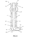
図3および図4を参照すると、複合入口−出口フローノズル270/271は、外側入口ノズル270および内側出口ノズル271を含む2つの同心状中空鍛造体から構成される。出口ノズル271は、原子炉シュラウド220(原子炉容器シェル201の内部)に溶接された一端と、蒸気発生容器300の入口ノズル371に溶接された反対側の端とを有する。入口ノズル270は、原子炉容器シェル201に溶接された一端と、蒸気発生容器300の出口ノズル370に溶接された反対側の端とを有する。流れ遮断板227は、原子炉容器から出ていく高温の一次冷却材の水が環状体221内に逆流できないことを確実にするのに役立つ。本実施形態では、原子炉容器の出口ノズル271および蒸気発生容器の入口ノズル371は各々、原子炉容器の入口ノズル270および蒸気発生容器の出口ノズル270より小さい直径を有する。複合入口−出口フローノズル270/271は封じ込め容器110の隔壁114より上に位置する。蒸気発生容器300の入口ノズル371および出口ノズル370は集合的に、蒸気発生容器のための同心配列嵌め合い複合入口/出口ノズル371/370を画定する。
With reference to FIGS. 3 and 4, the composite inlet-
「大破断」冷却材喪失事故(LOCA)事象の潜在的危険性を生み出す、原子炉一次冷却材システムにおける大きい配管の長いループを回避するために、原子炉容器200の複合入口−出口フローノズル270/271および蒸気発生容器の複合入口/出口ノズル371/370は両方とも、それぞれの容器のシェルに意図的に非常に密に結合され、シェルより半径方向にわずかに突出する。これは、図1および図2に示すように、入口/出口ノズルを介して原子炉容器200を蒸気発生容器300に直接結合することを可能にする。図3に示すように、原子炉容器の複合入口−出口フローノズル270/271は、支持フランジ280の半径方向の突出を超えない距離だけ、シェル201から半径方向に突出することが好ましい。原子炉容器200と蒸気発生容器300との間の入口/出口ノズル接続の全長は、特定の実施形態では、原子炉容器と蒸気発生容器との間の長い距離の大きい冷却材配管を排除するために、原子炉容器200および/または蒸気発生容器300の直径以下であることが好ましい。一実施形態では、原子炉容器200と蒸気発生容器300との間のノズル接続は、エルボまたはベンドを使用せず、直線状である。
In order to avoid long loops of large piping in the reactor primary coolant system, which creates the potential risk of a “large break” loss of coolant accident (LOCA) event, the combined inlet-
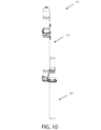
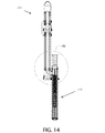
次に、蒸気発生容器300についてさらに詳しく説明する。図1〜図5を参照すると、一実施形態の蒸気発生容器300は、垂直軸線VA2を画定する円筒状シェル312を有する、垂直に配向された細長い構造体とすることができる。一実施形態では、蒸気発生容器の垂直軸線VA2は、蒸気発生容器が原子炉容器に横方向に隣接して配置されるように、原子炉容器200の垂直軸線VA2から水平方向に偏位する。一実施形態では、蒸気発生容器300は、少なくとも原子炉容器200の高さと同程度の高さを有する。蒸気発生容器は、下から上に予熱器320、主蒸気発生器330、過熱器350、および加圧器380を含み、これらを支持する。一実施形態では、予熱器320は蒸気発生器部330の底部によって形成され、したがって別個の管板を含まない。蒸気発生器組立体100の特定の配列および構成では、予熱器320は、システムの熱水力設計によっては省いてよい。
Next, the
一実施形態では、蒸気発生容器200は、本書に記載する原子炉容器支持体280と同様とすることのできるガセット支持フランジ400を含む。蒸気発生容器はシェル312に溶接し、図1に示すように隔壁114から支持することができる。
In one embodiment, the
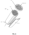
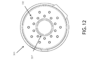
予熱器320、蒸気発生器330、および過熱器350は、各々が複数の平行直管332(すなわち管束)を有し、各管束の先端または端部に管を支持する管板333が配置されて成る、管状熱交換器である。一実施形態では、予熱器320、蒸気発生器330、および過熱器350は、二次冷却材(ランキンサイクル)が原子炉一次冷却材とは平行であるが逆の方向に流れる、平行向流型熱交換器配列を形成するように配置される(例えば図4および図5参照)。三つ組の上述した管状熱交換器(すなわち予熱器、蒸気発生器、および過熱器)は、管側(原子炉一次冷却材)およびシェル側(相を液体から過熱気体に変化させるランキンサイクルの作動流体を形成する二次冷却材)の両方で直列に流体接続される。
Each of the
蒸気発生容器300は、頂部310、底部311、軸線方向に延びる円筒状シェル312、およびシェル312と同心状に整列しかつ容器の中心線CL2上に位置する内部ライザ管337を含む。管332は、予熱器320、蒸気発生器330、および過熱器350を含む蒸気発生容器300の断面でライザ管とシェル312との間に、ライザ管337の外側の周りに周方向に配設される。一実施形態では、ライザ管337は、蒸気発生容器300の頂部から底部まで、予熱器320、蒸気発生器330、および過熱器350に関連付けられる管板333の全部に完全に延びて、原子炉容器200と加圧器380との間の連続した原子炉一次冷却材流路を形成する。
Steam generating
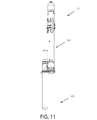
一実施形態では、蒸気発生容器は、上部過熱器部351と、ボルト締結フランジ継手352などによって蒸気発生器部に着脱自在に取り付けられる下部蒸気発生器部331とを含む。これは、蒸気発生器部331(蒸気発生器330および予熱器320を含むことができる)および過熱器部351(過熱器35および加圧器380を含むことができる)を別々に製作して、発電所敷地に輸送し、そこで組み立てることを可能にする。
In one embodiment, the steam generating container includes an upper superheater portion 351 and a lower steam generator portion 331 that is detachably attached to the steam generator portion by a bolt fastening flange joint 352 or the like. This is because the steam generator section 331 (which can include the
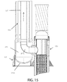
下部蒸気発生器部331は、上部過熱器部351の下部フランジチャネル335にボルトで締結された上部フランジチャネル334で頂部を終端して、集合的にフランジ継手352および中間プレナム339を形成する(図2参照)。蒸気発生器部331の底部は、図4に最もよく示すように、底部ヘッド336bで終端する。底部ヘッド336bはライザ管337とシェル312との間に環状空間を画定し、それは、一次冷却材を捕集して蒸気発生容器300から原子炉容器200に向かわせる底部プレナム338を形成する。底部ヘッド336bは、シェル312およびライザ管337と直角に配置される入口−出口フローノズル371/370を形成する。入口ノズル371は、一次冷却材の方向を水平から垂直に変えるために、エルボ371aによってライザ管337に流体連結することができる。
The lower steam generator section 331 terminates at the top with an
上部過熱器部351は、上述の通り、底部を下部フランジチャネル334で終端する。過熱器部351は、図2および図5に示すように、その上に加圧器380が配置され、それはライザ管337の頂部または出口および過熱器管332への入口の両方と流体連通する。一実施形態では、加圧器380は蒸気発生容器300のシェル312に直接取り付けられ、シェルの頂部ヘッド336aを形成する。一実施形態では、加圧器はドーム形または半球形のヘッドを有し、シェル312に溶接するか、あるいは代替的に、他の可能な実施形態ではボルトで締結することができる。加圧器380は、ライザ管337を上昇してくる原子炉一次冷却材を捕集して一次冷却材を過熱器管332に分配する、上部プレナムを形成する。加圧器380は、原子炉一次冷却材の圧力制御用の加熱/急冷要素381(すなわち水/蒸気)を含む。図2および図5に概略的に示すように、要素381は加圧器部に設置された一連の電熱器383を含み、それらは、一次冷却材の一部を沸騰させかつ加圧器の頂部のヘッド付近(破線で表される液体/気体界面340より上)に存在する蒸気泡を形成することによって、圧力を高めるように働く。水噴霧塔384は加圧器の頂部ヘッド336a付近に位置し、水を蒸気泡に噴射し、それによって蒸気を凝縮させ、蒸気泡の大きさを低減させる。蒸気泡のサイズの増大/縮小は、原子炉冷却材システム内の一次冷却材の圧力を増大/低減させるように働く。1つの例示的実施形態では、加圧器380および加熱/急冷要素381によって維持される代表的な一次冷却材圧力は約2,250psiとすることができるが、それに限定されない。
The upper superheater portion 351 terminates at the bottom with a
代替的実施形態では、上述の通り、液体/気体界面340は、加圧器380に接続された供給タンク(図示せず)によって供給される窒素(N2)のような不活性ガスと、液体一次冷却材との間に形成される。
In an alternative embodiment, as described above, the liquid /
加圧器380は、図示する通り溶接接続または代替的に一部の実施形態におけるボルト締結を含め、いずれかの適切な手段によって、図5に示す最上位または入口管板333より上の過熱器部351の頂部に接続することができる。一実施形態では、図2および図5に示す通り、加圧器380はドーム形または半球型の頂部またはヘッドを有することができる。
The
一実施形態では、過熱器管332の外面は、気体状過熱蒸気媒体の低下した熱伝達率を補償するために、一体的フィンを含むことができる。過熱器管束は、蒸気流が管束内の管を横切るのではなく、管に沿って平行な向流であることを確実にすることによって、(すなわち上昇流に微小水滴が同伴し続けることによって)腐食を防止する。
In one embodiment, the outer surface of the
図2および図4〜図5を参照すると、中間プレナム339を回って上昇流動する蒸気を運び、上部および下部フランジチャネル334、335をバイパスするために、少なくとも1つの略U字形蒸気バイパス配管ループ303が設けられる。蒸気配管ループ303は蒸気発生容器300のシェルに近接して配置され、かつできるだけ短くすることが好ましい。
With reference to FIGS. 2 and 4-5, at least one generally U-shaped steam
1つの非限定実施形態では、蒸気発生容器300はステンレス鋼のような耐食性金属から作ることができる。
In one non-limiting embodiment, the
次に、原子炉一次冷却材およびランキンサイクル用の二次冷却材の流路について説明する。図2および図3は蒸気発生器組立体100の原子炉一次冷却材の流路を示す。図4〜図5は主として、蒸気発生容器300中のランキンサイクルの二次冷却材の流路を示す。冷却された一次冷却材(「低温」)は出口ノズル370を介して蒸気発生容器300から流出し、外側入口ノズル270を介して原子炉容器200に流入する。一次冷却材は環状ダウンカマ222中を下方に流れ、ライザカラム224の底部に流入する。一次冷却材は燃料カートリッジ230中を上方に流れ、燃料炉心の対流および熱伝導によって加熱される。今加熱された、すなわち「高温」の一次冷却材は外側入口ノズル270を介して原子炉容器200を出て、入口ノズル371を介して蒸気発生容器300に入る。高温の一次冷却材はライザ管337内を垂直方向に上向きに流れ、「スタック」の頂部で加圧器380内に送られる。高温の一次冷却材は方向を逆転し、蒸気発生容器200中を下降し始める。高温の一次冷却材は最初に、シェル側でスタック内の下の蒸気発生器230から上方に流れる飽和蒸気(二次冷却材)を有する管束の管側で、過熱器350中を下降する。飽和蒸気は過熱状態になり、蒸気発生容器300から流出する。今温度が下がっていく高温の冷却材は蒸気発生容器300中を下降し続け、次に管側で蒸気発生器330中を進む。シェル側では、一次冷却材が熱を二次冷却材に渡してさらに冷却されるにつれて、液体二次冷却材は相変化を受け、蒸気に変化する。今さらに冷却された一次冷却材は管側で予熱器320中を下降し、蒸気発生器の上流の管束のシェル側の二次冷却材に遭遇してそれを予熱する。今冷却された一次冷却材は蒸気発生容器300および原子炉容器200中の閉流動ループを完了し、入口ノズル270を介して再び原子炉容器に流入する。
Next, the flow path of the reactor primary coolant and the secondary coolant for the Rankine cycle will be described. 2 and 3 show the reactor primary coolant flow path of the
一実施形態では、例示的非限定的な原子炉容器の「高温」出口温度は、約575°Fから約600°Fまでの範囲とすることができる。例示的非限定的な原子炉容器の「低温」入口温度は、約350°Fから385°Fまでの範囲とすることができる。例示的な原子炉容器の動作圧力は、加圧器380によって維持される約2,250psi(1平方インチ当たりポンド圧力)とすることができる。特定用途の熱伝達要件およびランキンサイクル側の蒸気生成動作パラメータに応じて、他の適切な流れの温度および圧力を使用することができる。一実施形態では、原子炉容器一次冷却材は非ホウ酸塩含有脱塩水とすることができる。
In one embodiment, an exemplary non-limiting reactor vessel “hot” outlet temperature can range from about 575 ° F. to about 600 ° F. An exemplary non-limiting reactor vessel “cold” inlet temperature can range from about 350 ° F. to 385 ° F. An exemplary reactor vessel operating pressure may be about 2,250 psi (pound pressure per square inch) maintained by the
1つの例示的実施形態では、蒸気発生容器のシェル312は、508型炭素鋼のような鋼製とすることができる。管312がインコネルから作製される場合、管板333は、インコネルを被覆した同じ鋼から作製することができる。
In one exemplary embodiment, the steam generating
本発明について、当業者がそれを容易に作製しかつ使用することができるように、充分に詳細に説明しかつ例証したので、本発明の精神および範囲から逸脱することなく、様々な変形、変化、および改善は容易に明らかになるはずである。 Since the present invention has been described and illustrated in sufficient detail to enable those skilled in the art to make and use it, various modifications and changes can be made without departing from the spirit and scope of the invention. , And improvements should be readily apparent.
Claims (42)
前記内部空洞内に配置された核燃料を備えた原子炉炉心と、
第2シェルおよび垂直積層関係に配置された複数の熱交換器部を備えた蒸気発生容器であって、前記蒸気発生容器の前記第2シェルが前記原子炉容器の前記第1シェルとは別個に形成され、流体継手を介して前記原子炉容器の前記第1シェルと一体に流体接続された、前記蒸気発生容器と、
前記原子炉容器と前記蒸気発生容器との間に形成された閉ループ一次冷却材システムであって、前記原子炉容器中を流れて前記原子炉炉心を冷却すると共に、前記蒸気発生容器中を流れて熱を、前記蒸気発生容器中を流れる二次冷却材に伝達する、一次冷却材を有する前記閉ループ一次冷却材システムと、
を備え、
前記原子炉容器は、第1出口ノズルと、前記第1出口ノズルと同心状に整列した第1入口ノズルとを含み、
前記蒸気発生容器は、第2出口ノズルと、前記第2出口ノズルと同心状に整列した第2入口ノズルとを含み、
前記原子炉容器の前記第1出口ノズルは、前記第1入口ノズル内に配置され、かつ前記蒸気発生容器の前記第2入口ノズルと流体接続され、
前記蒸気発生容器の前記第2入口ノズルは、前記第2出口ノズル内に配置され、
前記第2出口ノズルは、前記原子炉容器の前記第1入口ノズルと流体接続され、
前記閉ループ一次冷却材システムは、前記原子炉容器および前記蒸気発生容器中を流れる前記一次冷却材の循環が高温の前記一次冷却材密度と低温の前記一次冷却材の密度の差により生成される圧力水頭によって生じるように構成され、
前記二次冷却材は、前記蒸気発生容器の前記複数の熱交換器部の各々の中を前記縦方向に流れ、相を液体から蒸気に変化させ、
前記蒸気発生容器の前記複数の熱交換器部の各々は、下部蒸気発生部および前記下部蒸気発生部の上に配置された上部過熱器部を含み、前記上部過熱器部は、前記二次冷却材を過熱蒸気状態まで加熱するように動作可能であり、
前記蒸気発生容器は、前記下部蒸気発生部の頂部管板と前記上部過熱器部の底部管板との間に配置された中間フロープレナムを含み、前記一次冷却材は、前記上部過熱器部から前記下部蒸気発生部まで前記中間フロープレナム中を流れる、冷却材循環による原子力蒸気供給システム。 A longitudinally elongated reactor vessel with a first shell forming an internal cavity;
A nuclear reactor core with nuclear fuel disposed in the internal cavity;
A steam generation vessel comprising a second shell and a plurality of heat exchanger portions arranged in a vertically stacked relationship, wherein the second shell of the steam generation vessel is separate from the first shell of the reactor vessel The steam generating vessel formed and fluidly connected integrally with the first shell of the reactor vessel via a fluid coupling;
A closed-loop primary coolant system formed between the reactor vessel and the steam generation vessel, wherein the system cools the reactor core through the reactor vessel and flows through the steam generation vessel. The closed-loop primary coolant system with a primary coolant that transfers heat to a secondary coolant flowing in the steam generating vessel;
With
The reactor vessel includes a first outlet nozzle and a first inlet nozzle that is concentrically aligned with the first outlet nozzle;
The steam generation vessel includes a second outlet nozzle and a second inlet nozzle that is concentrically aligned with the second outlet nozzle;
The first outlet nozzle of the reactor vessel is disposed in the first inlet nozzle and fluidly connected to the second inlet nozzle of the steam generating vessel;
The second inlet nozzle of the steam generating container is disposed in the second outlet nozzle;
The second outlet nozzle is fluidly connected to the first inlet nozzle of the reactor vessel ;
Before Symbol closed loop primary coolant system, circulation of the primary coolant flowing through the reactor vessel and the steam generating vessel is generated by the difference in density of the high temperature of the primary coolant density and low temperature of the primary coolant Configured to be generated by pressure head,
The secondary coolant flows in the longitudinal direction through each of the plurality of heat exchanger parts of the steam generation container, and changes the phase from liquid to steam ,
Each of the plurality of heat exchanger parts of the steam generation container includes a lower steam generation part and an upper superheater part disposed on the lower steam generation part, and the upper superheater part includes the secondary cooling Operable to heat the material to a superheated steam state,
The steam generation container includes an intermediate flow plenum disposed between a top tube plate of the lower steam generation unit and a bottom tube plate of the upper superheater unit, and the primary coolant is supplied from the upper superheater unit. wherein Ru flows the in the intermediate flow plenum to the lower steam generator, the nuclear steam supply system by the coolant circulation.
前記一次冷却材は管側の前記複数の熱交換器部の各々の管中を下方に流れ、
前記二次冷却材は平行直交流型配置構成の前記複数の熱交換器部の各々のシェル側の管の間を上方に流れる、請求項1に記載のシステム。 Each of the plurality of heat exchanger portions includes a pair of vertically spaced tube plates and a tube bundle including the plurality of vertically oriented tubes extending between the tube plates. ,
The primary coolant flows downward in each tube of the plurality of heat exchanger sections on the tube side,
The system of claim 1, wherein the secondary coolant flows upward between the shell side tubes of each of the plurality of heat exchanger sections in a parallel cross flow configuration.
流動流体を導通させるために前記原子炉容器の前記内部空洞内に配置された垂直ライザおよびダウンカマであって、相互に流体連通している前記垂直ライザおよび前記ダウンカマと、
前記原子炉容器の前記内部空洞内に配置された核燃料を備えた原子炉炉心と、
第2垂直軸線と、垂直積層関係に流体接続された複数の熱交換器部を含む円筒形シェルとを有する、前記縦方向に細長い蒸気発生容器であって、前記蒸気発生容器の前記円筒形シェルが前記原子炉容器の前記シェルとは別個に形成され、流体継手を介して前記原子炉容器の前記シェルと一体に流体接続された、蒸気発生容器と、
前記原子炉炉心による加熱のために一次冷却材が前記原子炉容器の前記ダウンカマおよび前記垂直ライザを流れ、前記一次冷却材がさらに前記蒸気発生容器の前記複数の熱交換器部を流れて熱を、前記蒸気発生容器を流れる二次冷却材に伝達する、閉流動ループを有する原子炉一次冷却材システムと、
を備え、
前記原子炉容器は、第1出口ノズルと、前記第1出口ノズルと同心状に整列した第1入口ノズルとを含み、
前記蒸気発生容器は、第2出口ノズルと、前記第2出口ノズルと同心状に整列した第2入口ノズルとを含み、
前記原子炉容器の前記第1出口ノズルは、前記第1入口ノズル内に配置され、かつ前記蒸気発生容器の前記第2入口ノズルと流体接続され、
前記蒸気発生容器の前記第2入口ノズルは、前記第2出口ノズル内に配置され、
前記第2出口ノズルは、前記原子炉容器の前記第1入口ノズルと流体接続され、
前記一次冷却材システムは、前記原子炉容器および前記蒸気発生容器中を流れる前記一次冷却材の循環が高温の前記一次冷却材密度と低温の前記一次冷却材の密度の差により生成される圧力水頭によって生じるように構成され、
前記二次冷却材は前記蒸気発生容器の前記複数の熱交換器部を前記縦方向に流過して、相を液体から蒸気に変化させ、
前記原子炉容器の前記第1垂直軸線は前記蒸気発生容器の前記第2垂直軸線から側方に偏位し、
前記蒸気発生容器の前記複数の熱交換器部の各々は、下部蒸気発生部および前記下部蒸気発生部の上に配置された上部過熱器部を含み、前記上部過熱器部は、前記二次冷却材を過熱蒸気状態まで加熱するように動作可能であり、
前記蒸気発生容器は、前記下部蒸気発生部の頂部管板と前記上部過熱器部の底部管板との間に配置された中間フロープレナムを含み、前記一次冷却材は、前記上部過熱器部から前記下部蒸気発生部まで前記中間フロープレナム中を流れる、冷却材循環による原子力蒸気供給システム。 A longitudinally elongated reactor vessel with a shell having a first vertical axis and forming an internal cavity;
A vertical riser and a downcomer disposed in the internal cavity of the reactor vessel for conducting a flowing fluid, wherein the vertical riser and the downcomer are in fluid communication with each other;
A nuclear reactor core with nuclear fuel disposed within the internal cavity of the reactor vessel;
A longitudinally elongate steam generating vessel having a second vertical axis and a cylindrical shell including a plurality of heat exchanger portions fluidly connected in a vertically stacked relationship, wherein the cylindrical shell of the steam generating vessel A steam generating vessel formed separately from the shell of the reactor vessel and fluidly connected integrally with the shell of the reactor vessel via a fluid coupling;
A primary coolant flows through the downcomer and the vertical riser of the reactor vessel for heating by the reactor core, and the primary coolant further flows through the plurality of heat exchanger sections of the steam generation vessel to generate heat. A reactor primary coolant system having a closed flow loop that communicates to a secondary coolant flowing through the steam generating vessel;
With
The reactor vessel includes a first outlet nozzle and a first inlet nozzle that is concentrically aligned with the first outlet nozzle;
The steam generation vessel includes a second outlet nozzle and a second inlet nozzle that is concentrically aligned with the second outlet nozzle;
The first outlet nozzle of the reactor vessel is disposed in the first inlet nozzle and fluidly connected to the second inlet nozzle of the steam generating vessel;
The second inlet nozzle of the steam generating container is disposed in the second outlet nozzle;
The second outlet nozzle is fluidly connected to the first inlet nozzle of the reactor vessel ;
Before SL primary coolant system pressure circulation of the primary coolant flowing through the reactor vessel and the steam generating vessel is generated by the difference in density of the high temperature of the primary coolant density and low temperature of the primary coolant Configured to be produced by water heads,
The secondary coolant flows through the plurality of heat exchanger parts of the steam generation container in the longitudinal direction, and changes the phase from liquid to steam,
The first vertical axis of the reactor vessel is laterally offset from the second vertical axis of the steam generating vessel ;
Each of the plurality of heat exchanger parts of the steam generation container includes a lower steam generation part and an upper superheater part disposed on the lower steam generation part, and the upper superheater part includes the secondary cooling Operable to heat the material to a superheated steam state,
The steam generation container includes an intermediate flow plenum disposed between a top tube plate of the lower steam generation unit and a bottom tube plate of the upper superheater unit, and the primary coolant is supplied from the upper superheater unit. wherein Ru flows the in the intermediate flow plenum to the lower steam generator, the nuclear steam supply system by the coolant circulation.
前記一次冷却材は管側の前記複数の熱交換器部の各々の管中を下方に流れ、
前記二次冷却材は平行直交流型配置構成の前記複数の熱交換器部の各々のシェル側の管の間を上方に流れる、請求項20に記載のシステム。 Each of the plurality of heat exchanger portions includes a pair of vertically spaced tube plates and a tube bundle including the plurality of vertically oriented tubes extending between the tube plates. ,
The primary coolant flows downward in each tube of the plurality of heat exchanger sections on the tube side,
21. The system of claim 20 , wherein the secondary coolant flows upward between the shell side tubes of each of the plurality of heat exchanger sections in a parallel cross flow arrangement.
前記複数の熱交換器部の各々の前記複数の管は、前記蒸気発生容器の前記円筒形シェルと前記中央ライザ管との間で前記中央ライザ管の周囲に周方向間隔配置パターンで配設される、請求項34に記載のシステム。 The steam generation vessel includes a longitudinally extending central riser tube fluidly coupled to the reactor vessel, and the primary coolant flows upward from the reactor vessel into the central riser tube;
The plurality of tubes of each of the plurality of heat exchanger portions are disposed in a circumferentially spaced pattern around the central riser tube between the cylindrical shell of the steam generation vessel and the central riser tube. 35. The system of claim 34 .
加熱された前記一次冷却材を、前記原子炉炉心に流体接続された垂直ライザ内で第1垂直方向に前記原子炉容器中を上方に流過させるステップと、
加熱された前記一次冷却材を前記原子炉容器の頂部から原子炉容器出口ノズルを介して排出するステップと、
加熱された前記一次冷却材を蒸気発生容器の底部で前記原子炉容器出口ノズルと結合されている蒸気発生容器入口ノズルを介して受容するステップと、
加熱された前記一次冷却材を垂直ライザ管内で前記第1垂直方向に前記蒸気発生容器中を上方に流過させるステップと、
加熱された前記一次冷却材を前記蒸気発生容器の頂部で受容するステップと、
加熱された前記一次冷却材の流動の方向を前記第1垂直方向の上向きから第2垂直方向の下向きに上下反転させるステップと、
加熱された前記一次冷却材を前記蒸気発生容器中を前記第2垂直方向に下方に流過させ、そこで前記一次冷却材を冷却させるステップと、
冷却された前記一次冷却材を前記原子炉容器に原子炉容器入口ノズルと結合されている蒸気発生容器出口ノズルを介して還流させるステップと、
前記原子炉容器における前記加熱するステップを繰り返すステップと、
を含む方法であって、
前記原子炉容器出口ノズルは、前記原子炉容器入口ノズル内に同心状に配置され、
前記蒸気発生容器入口ノズルは、前記蒸気発生容器出口ノズル内に同心状に配置され、
前記原子炉容器によって排出される前記一次冷却材は、前記原子炉容器に還流される前記一次冷却材の内部を流過し、
前記原子炉容器および前記蒸気発生容器中の前記一次冷却材の流れが閉循環流動ループを形成し、
前記方法は、二次冷却材を、前記一次冷却材の前記第1垂直方向および前記第2垂直方向と平行に、前記蒸気発生容器中を上方に流過させるステップをさらに含み、
前記蒸気発生容器は、複数の熱交換器部を備え、
前記蒸気発生容器の前記複数の熱交換器部の各々は、下部蒸気発生部および前記下部蒸気発生部の上に配置された上部過熱器部を含み、前記上部過熱器部は、前記二次冷却材を過熱蒸気状態まで加熱するように動作可能であり、
前記蒸気発生容器は、前記下部蒸気発生部の頂部管板と前記上部過熱器部の底部管板との間に配置された中間フロープレナムを含み、前記一次冷却材は、前記上部過熱器部から前記下部蒸気発生部まで前記中間フロープレナム中を流れる、加圧水型原子炉システムで蒸気を発生させる方法。 Heating the liquid primary coolant in a reactor core disposed in the reactor vessel;
Flowing the heated primary coolant upward in the reactor vessel in a first vertical direction in a vertical riser fluidly connected to the reactor core;
Discharging the heated primary coolant from the top of the reactor vessel through a reactor vessel outlet nozzle;
A step of receiving through the steam generating vessel inlet nozzle coupled with heated said primary coolant at the bottom of the steam generator vessel and the reactor vessel outlet nozzles,
Allowing the heated primary coolant to flow upwardly through the steam generating vessel in the first vertical direction in a vertical riser tube;
Receiving the heated primary coolant at the top of the steam generating vessel;
Reversing the direction of flow of the heated primary coolant from the first vertical direction upward to the second vertical direction downward;
Allowing the heated primary coolant to flow downward in the steam generating vessel in the second vertical direction, where the primary coolant is cooled;
Refluxing the cooled primary coolant to the reactor vessel via a steam generating vessel outlet nozzle coupled to a reactor vessel inlet nozzle;
Repeating the heating step in the reactor vessel;
The A including method,
The reactor vessel outlet nozzle is disposed concentrically within the reactor vessel inlet nozzle,
The steam generation container inlet nozzle is disposed concentrically within the steam generation container outlet nozzle,
The primary coolant discharged by the reactor vessel flows through the interior of the primary coolant that is recirculated to the reactor vessel ;
Flow of the primary coolant before Symbol reactor vessel and the steam generator in the container to form a closed circulating fluidized loop,
The method further includes flowing a secondary coolant upward in the steam generation vessel in parallel with the first vertical direction and the second vertical direction of the primary coolant;
The steam generation container includes a plurality of heat exchanger units,
Each of the plurality of heat exchanger parts of the steam generation container includes a lower steam generation part and an upper superheater part disposed on the lower steam generation part, and the upper superheater part includes the secondary cooling Operable to heat the material to a superheated steam state,
The steam generation container includes an intermediate flow plenum disposed between a top tube plate of the lower steam generation unit and a bottom tube plate of the upper superheater unit, and the primary coolant is supplied from the upper superheater unit. A method of generating steam in a pressurized water reactor system that flows through the intermediate flow plenum to the lower steam generator .
Applications Claiming Priority (3)
| Application Number | Priority Date | Filing Date | Title |
|---|---|---|---|
| US201261638257P | 2012-04-25 | 2012-04-25 | |
| US61/638,257 | 2012-04-25 | ||
| PCT/US2013/038289 WO2013163475A1 (en) | 2012-04-25 | 2013-04-25 | Nuclear steam supply system |
Publications (2)
| Publication Number | Publication Date |
|---|---|
| JP2015521278A JP2015521278A (en) | 2015-07-27 |
| JP6232051B2 true JP6232051B2 (en) | 2017-11-15 |
Family
ID=49483904
Family Applications (1)
| Application Number | Title | Priority Date | Filing Date |
|---|---|---|---|
| JP2015509152A Expired - Fee Related JP6232051B2 (en) | 2012-04-25 | 2013-04-25 | Nuclear steam supply system and method |
Country Status (8)
| Country | Link |
|---|---|
| US (1) | US9852820B2 (en) |
| EP (1) | EP2842135B1 (en) |
| JP (1) | JP6232051B2 (en) |
| KR (1) | KR101630428B1 (en) |
| CN (1) | CN104508754B (en) |
| ES (1) | ES2687524T3 (en) |
| RU (1) | RU2014147151A (en) |
| WO (1) | WO2013163475A1 (en) |
Families Citing this family (21)
| Publication number | Priority date | Publication date | Assignee | Title |
|---|---|---|---|---|
| WO2015061641A1 (en) * | 2013-10-24 | 2015-04-30 | Holtec International | Steam generator for nuclear steam supply system |
| US11901088B2 (en) | 2012-05-04 | 2024-02-13 | Smr Inventec, Llc | Method of heating primary coolant outside of primary coolant loop during a reactor startup operation |
| US12512230B2 (en) | 2012-05-04 | 2025-12-30 | Smr Inventec, Llc | Passively-cooled spent nuclear fuel pool system |
| FR3022676B1 (en) * | 2014-06-23 | 2019-07-26 | Dcns | NUCLEAR REACTOR STRUCTURE |
| RU2608826C2 (en) * | 2015-06-01 | 2017-01-25 | Российская Федерация, от имени которой выступает Государственная корпорация по атомной энергии "Росатом" - Госкорпорация "Росатом" | Device for passive protection of nuclear reactor |
| KR101897984B1 (en) * | 2015-06-11 | 2018-09-13 | 한국원자력연구원 | Module type nuclear reactor and nuclear power plant having the same |
| KR101626270B1 (en) * | 2016-02-26 | 2016-05-31 | 문인득 | Apparatus for installing u-shaped module pipe on the closure loop of reactor coolant system |
| CN105679382A (en) * | 2016-03-25 | 2016-06-15 | 上海核工程研究设计院 | Nuclear power station primary loop main equipment direct connecting manner |
| DE102016206906A1 (en) * | 2016-04-22 | 2017-10-26 | Areva Gmbh | Passive level control system |
| KR101744318B1 (en) * | 2016-07-27 | 2017-06-07 | 한국전력기술 주식회사 | Externally Integrated Once-Through Steam generator Small Modular Reactor |
| US10706973B2 (en) * | 2017-05-02 | 2020-07-07 | Ge-Hitachi Nuclear Energy Americas Llc | Very simplified boiling water reactors for commercial electricity generation |
| WO2019067819A1 (en) * | 2017-09-28 | 2019-04-04 | Westinghouse Electric Company Llc | Plate type nuclear micro reactor |
| KR102049954B1 (en) * | 2017-10-26 | 2019-11-28 | 한국원자력연구원 | Connecting apparatus for steam generator and integral reactor including the same |
| RU2687054C1 (en) * | 2018-06-06 | 2019-05-07 | федеральное государственное автономное образовательное учреждение высшего образования "Национальный исследовательский ядерный университет "МИФИ" (НИЯУ МИФИ) | Nuclear reactor |
| CZ308993B6 (en) * | 2020-05-07 | 2021-11-10 | Witkowitz Atomica A.S. | An energy source using low-enriched nuclear fuel to produce heat |
| CN112098131B (en) * | 2020-09-15 | 2021-12-24 | 上海交通大学 | A steam generator simulation device for simulating the non-uniform inflow of nuclear main pump inlet |
| KR102310443B1 (en) * | 2020-11-25 | 2021-10-08 | 한국수력원자력 주식회사 | Apparatus for injecting steam |
| CN113654016B (en) * | 2021-09-18 | 2023-03-14 | 中国核动力研究设计院 | Steam generator steam generation assembly, leakage detection method and device |
| CN114255892B (en) * | 2021-12-21 | 2025-05-06 | 中国船舶重工集团公司第七一九研究所 | A nuclear steam supply system |
| CN114596974B (en) * | 2021-12-28 | 2024-07-16 | 中核武汉核电运行技术股份有限公司 | Split type plug transmission device |
| CN115031214B (en) * | 2022-06-14 | 2024-04-02 | 中国核动力研究设计院 | External direct-current efficient steam generator with built-in voltage stabilizing function |
Family Cites Families (21)
| Publication number | Priority date | Publication date | Assignee | Title |
|---|---|---|---|---|
| US828714A (en) | 1906-03-27 | 1906-08-14 | William F Cook | Tube well strainer. |
| GB1115075A (en) * | 1964-06-29 | 1968-05-22 | Atomic Energy Authority Uk | Improvements in and relating to vapour generators |
| FR2265152A1 (en) * | 1974-03-20 | 1975-10-17 | Commissariat Energie Atomique | Pressure water nuclear reactor - with external heat exchangers and pumps for use as steam generator on a ship |
| DE2706216A1 (en) * | 1977-02-14 | 1978-08-17 | Kraftwerk Union Ag | BURST-PROOF NUCLEAR REACTOR PLANT WITH PRESSURE WATER REACTOR |
| FR2434461A1 (en) | 1978-06-23 | 1980-03-21 | Bretagne Atel Chantiers | NEW SUPPORT AND PROTECTION DEVICE FOR NUCLEAR BOILERS |
| JPS5810675A (en) * | 1981-07-13 | 1983-01-21 | 株式会社日立製作所 | Reactor |
| JPS6230996A (en) * | 1985-08-02 | 1987-02-09 | 株式会社東芝 | Cooling device for liquid-metal cooling type nuclear reactor |
| US4753771A (en) * | 1986-02-07 | 1988-06-28 | Westinghouse Electric Corp. | Passive safety system for a pressurized water nuclear reactor |
| DE3620672A1 (en) * | 1986-06-20 | 1987-12-23 | Wilhelm Odendahl | Dual-cycle nuclear reactor |
| JP2537538B2 (en) * | 1988-06-16 | 1996-09-25 | 株式会社日立製作所 | Natural circulation type reactor |
| US5158742A (en) * | 1991-12-11 | 1992-10-27 | General Electric Company | Reactor steam isolation cooling system |
| JP2999053B2 (en) * | 1992-02-27 | 2000-01-17 | 三菱重工業株式会社 | Pressurized water reactor plant |
| JP2963586B2 (en) * | 1992-09-24 | 1999-10-18 | 株式会社日立製作所 | Steam generator |
| CA2150275C (en) | 1995-05-26 | 2008-10-14 | Norman J. Spinks | Passive emergency water system for water-cooled nuclear reactors |
| US5828714A (en) * | 1996-12-19 | 1998-10-27 | Westinghouse Electric Corporation | Enhanced passive safety system for a nuclear pressurized water reactor |
| JP2002333288A (en) * | 2001-05-08 | 2002-11-22 | Mitsubishi Heavy Ind Ltd | Steam generator |
| JP2005274337A (en) * | 2004-03-24 | 2005-10-06 | Mitsubishi Heavy Ind Ltd | Nuclear reactor |
| JP4592773B2 (en) * | 2008-02-29 | 2010-12-08 | 株式会社東芝 | Static cooling decompression system and pressurized water nuclear plant |
| WO2011097597A1 (en) * | 2010-02-05 | 2011-08-11 | Smr, Llc | Nuclear reactor system having natural circulation of primary coolant |
| US9177674B2 (en) * | 2010-09-27 | 2015-11-03 | Bwxt Nuclear Energy, Inc. | Compact nuclear reactor |
| US9343187B2 (en) * | 2010-09-27 | 2016-05-17 | Bwxt Nuclear Energy, Inc. | Compact nuclear reactor with integral steam generator |
-
2013
- 2013-04-25 CN CN201380024421.1A patent/CN104508754B/en not_active Expired - Fee Related
- 2013-04-25 US US14/397,135 patent/US9852820B2/en not_active Expired - Fee Related
- 2013-04-25 RU RU2014147151A patent/RU2014147151A/en not_active Application Discontinuation
- 2013-04-25 JP JP2015509152A patent/JP6232051B2/en not_active Expired - Fee Related
- 2013-04-25 WO PCT/US2013/038289 patent/WO2013163475A1/en not_active Ceased
- 2013-04-25 EP EP13781452.1A patent/EP2842135B1/en active Active
- 2013-04-25 ES ES13781452.1T patent/ES2687524T3/en active Active
- 2013-04-25 KR KR1020147032909A patent/KR101630428B1/en not_active Expired - Fee Related
Also Published As
| Publication number | Publication date |
|---|---|
| WO2013163475A1 (en) | 2013-10-31 |
| EP2842135A4 (en) | 2016-03-02 |
| JP2015521278A (en) | 2015-07-27 |
| RU2014147151A (en) | 2016-06-10 |
| CN104508754A (en) | 2015-04-08 |
| US20150110236A1 (en) | 2015-04-23 |
| ES2687524T3 (en) | 2018-10-25 |
| CN104508754B (en) | 2017-04-05 |
| EP2842135A1 (en) | 2015-03-04 |
| KR101630428B1 (en) | 2016-06-14 |
| US9852820B2 (en) | 2017-12-26 |
| EP2842135B1 (en) | 2018-07-11 |
| KR20150023285A (en) | 2015-03-05 |
Similar Documents
| Publication | Publication Date | Title |
|---|---|---|
| JP6232051B2 (en) | Nuclear steam supply system and method | |
| US11120920B2 (en) | Steam generator for nuclear steam supply system | |
| US20120307956A1 (en) | Nuclear reactor system having natural circulation of primary coolant | |
| US11901088B2 (en) | Method of heating primary coolant outside of primary coolant loop during a reactor startup operation | |
| US11935663B2 (en) | Control rod drive system for nuclear reactor | |
| KR20130118862A (en) | Compact nuclear reactor with integral steam generator | |
| US10720249B2 (en) | Passive reactor cooling system | |
| JP2014512013A (en) | Integrated compact pressurized water reactor | |
| EP3005373A1 (en) | Passive reactor cooling system | |
| US20200388411A1 (en) | Nuclear steam supply system | |
| US12512230B2 (en) | Passively-cooled spent nuclear fuel pool system | |
| US20240266081A1 (en) | Nuclear fuel core and methods of fueling and/or defueling a nuclear reactor, control rod drive system for nuclear reactor, shutdown system for nuclear steam supply system, nuclear reactor shroud, and/or loss-of-coolant accident reactor cooling system | |
| Singh et al. | On the Thermal-Hydraulic Essentials of the H oltec I nherently S afe M odular U nderground R eactor (HI-SMUR) System | |
| KR20250109727A (en) | Safety condenser and reactor containing same | |
| Park et al. | Mechanical Design Features of PGSFR NSSS |
Legal Events
| Date | Code | Title | Description |
|---|---|---|---|
| A131 | Notification of reasons for refusal |
Free format text: JAPANESE INTERMEDIATE CODE: A131 Effective date: 20151201 |
|
| A521 | Request for written amendment filed |
Free format text: JAPANESE INTERMEDIATE CODE: A523 Effective date: 20160223 |
|
| A131 | Notification of reasons for refusal |
Free format text: JAPANESE INTERMEDIATE CODE: A131 Effective date: 20160809 |
|
| A521 | Request for written amendment filed |
Free format text: JAPANESE INTERMEDIATE CODE: A523 Effective date: 20161107 |
|
| A02 | Decision of refusal |
Free format text: JAPANESE INTERMEDIATE CODE: A02 Effective date: 20170404 |
|
| A521 | Request for written amendment filed |
Free format text: JAPANESE INTERMEDIATE CODE: A523 Effective date: 20170712 |
|
| A911 | Transfer to examiner for re-examination before appeal (zenchi) |
Free format text: JAPANESE INTERMEDIATE CODE: A911 Effective date: 20170816 |
|
| TRDD | Decision of grant or rejection written | ||
| A01 | Written decision to grant a patent or to grant a registration (utility model) |
Free format text: JAPANESE INTERMEDIATE CODE: A01 Effective date: 20171017 |
|
| A61 | First payment of annual fees (during grant procedure) |
Free format text: JAPANESE INTERMEDIATE CODE: A61 Effective date: 20171020 |
|
| R150 | Certificate of patent or registration of utility model |
Ref document number: 6232051 Country of ref document: JP Free format text: JAPANESE INTERMEDIATE CODE: R150 |
|
| R250 | Receipt of annual fees |
Free format text: JAPANESE INTERMEDIATE CODE: R250 |
|
| R250 | Receipt of annual fees |
Free format text: JAPANESE INTERMEDIATE CODE: R250 |
|
| R250 | Receipt of annual fees |
Free format text: JAPANESE INTERMEDIATE CODE: R250 |
|
| R250 | Receipt of annual fees |
Free format text: JAPANESE INTERMEDIATE CODE: R250 |
|
| LAPS | Cancellation because of no payment of annual fees |