JP6232044B2 - Photonic needle system using measurement integration time based on needle displacement rate - Google Patents
Photonic needle system using measurement integration time based on needle displacement rate Download PDFInfo
- Publication number
- JP6232044B2 JP6232044B2 JP2015501014A JP2015501014A JP6232044B2 JP 6232044 B2 JP6232044 B2 JP 6232044B2 JP 2015501014 A JP2015501014 A JP 2015501014A JP 2015501014 A JP2015501014 A JP 2015501014A JP 6232044 B2 JP6232044 B2 JP 6232044B2
- Authority
- JP
- Japan
- Prior art keywords
- instrument
- tissue
- guidance system
- mode
- image
- Prior art date
- Legal status (The legal status is an assumption and is not a legal conclusion. Google has not performed a legal analysis and makes no representation as to the accuracy of the status listed.)
- Active
Links
Images

Classifications
-
- A—HUMAN NECESSITIES
- A61—MEDICAL OR VETERINARY SCIENCE; HYGIENE
- A61B—DIAGNOSIS; SURGERY; IDENTIFICATION
- A61B34/00—Computer-aided surgery; Manipulators or robots specially adapted for use in surgery
- A61B34/20—Surgical navigation systems; Devices for tracking or guiding surgical instruments, e.g. for frameless stereotaxis
-
- A—HUMAN NECESSITIES
- A61—MEDICAL OR VETERINARY SCIENCE; HYGIENE
- A61B—DIAGNOSIS; SURGERY; IDENTIFICATION
- A61B5/00—Measuring for diagnostic purposes; Identification of persons
- A61B5/0033—Features or image-related aspects of imaging apparatus, e.g. for MRI, optical tomography or impedance tomography apparatus; Arrangements of imaging apparatus in a room
- A61B5/0035—Features or image-related aspects of imaging apparatus, e.g. for MRI, optical tomography or impedance tomography apparatus; Arrangements of imaging apparatus in a room adapted for acquisition of images from more than one imaging mode, e.g. combining MRI and optical tomography
-
- A—HUMAN NECESSITIES
- A61—MEDICAL OR VETERINARY SCIENCE; HYGIENE
- A61B—DIAGNOSIS; SURGERY; IDENTIFICATION
- A61B5/00—Measuring for diagnostic purposes; Identification of persons
- A61B5/0059—Measuring for diagnostic purposes; Identification of persons using light, e.g. diagnosis by transillumination, diascopy, fluorescence
- A61B5/0071—Measuring for diagnostic purposes; Identification of persons using light, e.g. diagnosis by transillumination, diascopy, fluorescence by measuring fluorescence emission
-
- A—HUMAN NECESSITIES
- A61—MEDICAL OR VETERINARY SCIENCE; HYGIENE
- A61B—DIAGNOSIS; SURGERY; IDENTIFICATION
- A61B5/00—Measuring for diagnostic purposes; Identification of persons
- A61B5/0059—Measuring for diagnostic purposes; Identification of persons using light, e.g. diagnosis by transillumination, diascopy, fluorescence
- A61B5/0075—Measuring for diagnostic purposes; Identification of persons using light, e.g. diagnosis by transillumination, diascopy, fluorescence by spectroscopy, i.e. measuring spectra, e.g. Raman spectroscopy, infrared absorption spectroscopy
-
- A—HUMAN NECESSITIES
- A61—MEDICAL OR VETERINARY SCIENCE; HYGIENE
- A61B—DIAGNOSIS; SURGERY; IDENTIFICATION
- A61B5/00—Measuring for diagnostic purposes; Identification of persons
- A61B5/0059—Measuring for diagnostic purposes; Identification of persons using light, e.g. diagnosis by transillumination, diascopy, fluorescence
- A61B5/0082—Measuring for diagnostic purposes; Identification of persons using light, e.g. diagnosis by transillumination, diascopy, fluorescence adapted for particular medical purposes
- A61B5/0084—Measuring for diagnostic purposes; Identification of persons using light, e.g. diagnosis by transillumination, diascopy, fluorescence adapted for particular medical purposes for introduction into the body, e.g. by catheters
-
- A—HUMAN NECESSITIES
- A61—MEDICAL OR VETERINARY SCIENCE; HYGIENE
- A61B—DIAGNOSIS; SURGERY; IDENTIFICATION
- A61B5/00—Measuring for diagnostic purposes; Identification of persons
- A61B5/06—Devices, other than using radiation, for detecting or locating foreign bodies ; Determining position of diagnostic devices within or on the body of the patient
- A61B5/065—Determining position of the probe employing exclusively positioning means located on or in the probe, e.g. using position sensors arranged on the probe
- A61B5/066—Superposing sensor position on an image of the patient, e.g. obtained by ultrasound or x-ray imaging
-
- A—HUMAN NECESSITIES
- A61—MEDICAL OR VETERINARY SCIENCE; HYGIENE
- A61B—DIAGNOSIS; SURGERY; IDENTIFICATION
- A61B5/00—Measuring for diagnostic purposes; Identification of persons
- A61B5/68—Arrangements of detecting, measuring or recording means, e.g. sensors, in relation to patient
- A61B5/6846—Arrangements of detecting, measuring or recording means, e.g. sensors, in relation to patient specially adapted to be brought in contact with an internal body part, i.e. invasive
- A61B5/6847—Arrangements of detecting, measuring or recording means, e.g. sensors, in relation to patient specially adapted to be brought in contact with an internal body part, i.e. invasive mounted on an invasive device
- A61B5/6848—Needles
-
- A—HUMAN NECESSITIES
- A61—MEDICAL OR VETERINARY SCIENCE; HYGIENE
- A61B—DIAGNOSIS; SURGERY; IDENTIFICATION
- A61B5/00—Measuring for diagnostic purposes; Identification of persons
- A61B5/74—Details of notification to user or communication with user or patient; User input means
- A61B5/742—Details of notification to user or communication with user or patient; User input means using visual displays
- A61B5/7425—Displaying combinations of multiple images regardless of image source, e.g. displaying a reference anatomical image with a live image
-
- A—HUMAN NECESSITIES
- A61—MEDICAL OR VETERINARY SCIENCE; HYGIENE
- A61B—DIAGNOSIS; SURGERY; IDENTIFICATION
- A61B6/00—Apparatus or devices for radiation diagnosis; Apparatus or devices for radiation diagnosis combined with radiation therapy equipment
- A61B6/12—Arrangements for detecting or locating foreign bodies
-
- A—HUMAN NECESSITIES
- A61—MEDICAL OR VETERINARY SCIENCE; HYGIENE
- A61B—DIAGNOSIS; SURGERY; IDENTIFICATION
- A61B6/00—Apparatus or devices for radiation diagnosis; Apparatus or devices for radiation diagnosis combined with radiation therapy equipment
- A61B6/52—Devices using data or image processing specially adapted for radiation diagnosis
- A61B6/5211—Devices using data or image processing specially adapted for radiation diagnosis involving processing of medical diagnostic data
- A61B6/5217—Devices using data or image processing specially adapted for radiation diagnosis involving processing of medical diagnostic data extracting a diagnostic or physiological parameter from medical diagnostic data
-
- A—HUMAN NECESSITIES
- A61—MEDICAL OR VETERINARY SCIENCE; HYGIENE
- A61B—DIAGNOSIS; SURGERY; IDENTIFICATION
- A61B34/00—Computer-aided surgery; Manipulators or robots specially adapted for use in surgery
- A61B34/20—Surgical navigation systems; Devices for tracking or guiding surgical instruments, e.g. for frameless stereotaxis
- A61B2034/2046—Tracking techniques
- A61B2034/2048—Tracking techniques using an accelerometer or inertia sensor
-
- A—HUMAN NECESSITIES
- A61—MEDICAL OR VETERINARY SCIENCE; HYGIENE
- A61B—DIAGNOSIS; SURGERY; IDENTIFICATION
- A61B34/00—Computer-aided surgery; Manipulators or robots specially adapted for use in surgery
- A61B34/20—Surgical navigation systems; Devices for tracking or guiding surgical instruments, e.g. for frameless stereotaxis
- A61B2034/2046—Tracking techniques
- A61B2034/2051—Electromagnetic tracking systems
-
- A—HUMAN NECESSITIES
- A61—MEDICAL OR VETERINARY SCIENCE; HYGIENE
- A61B—DIAGNOSIS; SURGERY; IDENTIFICATION
- A61B34/00—Computer-aided surgery; Manipulators or robots specially adapted for use in surgery
- A61B34/20—Surgical navigation systems; Devices for tracking or guiding surgical instruments, e.g. for frameless stereotaxis
- A61B2034/2046—Tracking techniques
- A61B2034/2061—Tracking techniques using shape-sensors, e.g. fiber shape sensors with Bragg gratings
-
- A—HUMAN NECESSITIES
- A61—MEDICAL OR VETERINARY SCIENCE; HYGIENE
- A61B—DIAGNOSIS; SURGERY; IDENTIFICATION
- A61B90/00—Instruments, implements or accessories specially adapted for surgery or diagnosis and not covered by any of the groups A61B1/00 - A61B50/00, e.g. for luxation treatment or for protecting wound edges
- A61B90/36—Image-producing devices or illumination devices not otherwise provided for
- A61B90/37—Surgical systems with images on a monitor during operation
- A61B2090/376—Surgical systems with images on a monitor during operation using X-rays, e.g. fluoroscopy
-
- A—HUMAN NECESSITIES
- A61—MEDICAL OR VETERINARY SCIENCE; HYGIENE
- A61B—DIAGNOSIS; SURGERY; IDENTIFICATION
- A61B5/00—Measuring for diagnostic purposes; Identification of persons
- A61B5/68—Arrangements of detecting, measuring or recording means, e.g. sensors, in relation to patient
- A61B5/6846—Arrangements of detecting, measuring or recording means, e.g. sensors, in relation to patient specially adapted to be brought in contact with an internal body part, i.e. invasive
- A61B5/6847—Arrangements of detecting, measuring or recording means, e.g. sensors, in relation to patient specially adapted to be brought in contact with an internal body part, i.e. invasive mounted on an invasive device
- A61B5/6852—Catheters
-
- A—HUMAN NECESSITIES
- A61—MEDICAL OR VETERINARY SCIENCE; HYGIENE
- A61B—DIAGNOSIS; SURGERY; IDENTIFICATION
- A61B90/00—Instruments, implements or accessories specially adapted for surgery or diagnosis and not covered by any of the groups A61B1/00 - A61B50/00, e.g. for luxation treatment or for protecting wound edges
- A61B90/30—Devices for illuminating a surgical field, the devices having an interrelation with other surgical devices or with a surgical procedure
-
- A—HUMAN NECESSITIES
- A61—MEDICAL OR VETERINARY SCIENCE; HYGIENE
- A61B—DIAGNOSIS; SURGERY; IDENTIFICATION
- A61B90/00—Instruments, implements or accessories specially adapted for surgery or diagnosis and not covered by any of the groups A61B1/00 - A61B50/00, e.g. for luxation treatment or for protecting wound edges
- A61B90/36—Image-producing devices or illumination devices not otherwise provided for
- A61B90/361—Image-producing devices, e.g. surgical cameras
Landscapes
- Health & Medical Sciences (AREA)
- Life Sciences & Earth Sciences (AREA)
- Engineering & Computer Science (AREA)
- Medical Informatics (AREA)
- Surgery (AREA)
- Veterinary Medicine (AREA)
- Animal Behavior & Ethology (AREA)
- Physics & Mathematics (AREA)
- Public Health (AREA)
- General Health & Medical Sciences (AREA)
- Biomedical Technology (AREA)
- Heart & Thoracic Surgery (AREA)
- Molecular Biology (AREA)
- Biophysics (AREA)
- Pathology (AREA)
- Nuclear Medicine, Radiotherapy & Molecular Imaging (AREA)
- Radiology & Medical Imaging (AREA)
- Human Computer Interaction (AREA)
- Optics & Photonics (AREA)
- High Energy & Nuclear Physics (AREA)
- Robotics (AREA)
- Gynecology & Obstetrics (AREA)
- Spectroscopy & Molecular Physics (AREA)
- Physiology (AREA)
- Computer Vision & Pattern Recognition (AREA)
- Investigating Or Analysing Materials By Optical Means (AREA)
- Endoscopes (AREA)
- Investigating, Analyzing Materials By Fluorescence Or Luminescence (AREA)
- Measuring And Recording Apparatus For Diagnosis (AREA)
- Apparatus For Radiation Diagnosis (AREA)
Description
本発明は、体において器具を誘導するためのシステムに関する。 The present invention relates to a system for guiding an instrument in the body.
体に器具を誘導することを含む処置を実行するとき、器具の位置に関する視覚的なフィードバックが処置を実行している人に与えられることが有利である。更に、処置を実行している人は、どのタイプの組織が器具の箇所に存在するかに関する情報から利益を得ることができる。 When performing a procedure that includes guiding the instrument to the body, it is advantageous that visual feedback regarding the position of the instrument is provided to the person performing the procedure. Furthermore, the person performing the procedure can benefit from information regarding what type of tissue is present at the site of the instrument.
針は、手術前画像に基づき体内における特定の位置に配置される多くのデバイス又は器具の1つである。画像は、磁気共鳴撮像、コンピュータ断層撮影といったさまざまなモダリティ(撮像技術)で得られ、又は例えばXperCT(TM)といった画像再構成で得られる。配置の1つの目標は、配置の間、針の経路を慎重に選択することにより、周囲組織に対する損傷を最小化することである。 A needle is one of many devices or instruments that are placed at specific locations in the body based on pre-operative images. Images can be obtained with various modalities (imaging techniques) such as magnetic resonance imaging, computed tomography, or image reconstruction such as XperCT (TM). One goal of placement is to minimize damage to surrounding tissue by careful selection of the needle path during placement.
X線器具誘導を用いると、例えば蛍光透視の下での器具誘導のほぼリアルタイムなモニタリングを可能にすることができる。光学針は、誘導及び情報として組織フィードバックを提供するよう構成されるデバイスの1つの例である。光学針は、組織に対して光学的信号を送信し、及びこれを受信する。これらの2つの技術を組み合わせることにより、体に対する器具先端の位置及びその位置での組織情報の表示が可能である。 Using X-ray instrument guidance can allow near real-time monitoring of instrument guidance, for example under fluoroscopy. An optical needle is one example of a device configured to provide tissue feedback as guidance and information. The optical needle transmits and receives optical signals to the tissue. By combining these two techniques, it is possible to display the position of the instrument tip with respect to the body and the tissue information at that position.
光学的信号を用いて組織情報を得るため、光学スペクトルが取得され、組織情報を作成するために処理されなければならない。更に、この情報は、X線端末又は他のタイプの撮像デバイスに送られ、画像における器具位置にリンクされ、最終的に表示されなければならない。これらすべてのステップは、大量の時間を必要とし、表示されたデータがもはや、実際の位置を表していない場合がある。特に器具が比較的急速に前進されるとき、組織情報は遅れている場合がある。 In order to obtain tissue information using optical signals, an optical spectrum must be acquired and processed to create tissue information. In addition, this information must be sent to an X-ray terminal or other type of imaging device, linked to the instrument position in the image, and finally displayed. All these steps are time consuming and the displayed data may no longer represent the actual location. The tissue information may be delayed, especially when the instrument is advanced relatively quickly.
本発明の発明者は、改良されたシステム及び方法が有益であると理解し、結論的に本発明を考案した。 The inventor of the present invention has realized that the improved system and method are beneficial and has devised the present invention in conclusion.
ユーザに対して改良された画像フィードバックを実現することは、有利である。移動の間、結合された組織情報及び器具位置の表示を可能にすることも、望ましい。一般に、本発明は、好ましくは、単独で又は任意の組合せにおいて、上述の不利な点の1つ又は複数を緩和、軽減又は除去しようとするものである。特に、本発明の目的は、従来技術における上述した問題又は他の問題を解決する方法を提供することである。 It would be advantageous to achieve improved image feedback for the user. It would also be desirable to allow the display of combined tissue information and instrument position during movement. In general, the present invention preferably seeks to mitigate, alleviate or eliminate one or more of the above-mentioned disadvantages, alone or in any combination. In particular, the object of the present invention is to provide a method for solving the above-mentioned problems or other problems in the prior art.
これらの懸念の1つ又は複数を好適に解決するため、本発明の第1の側面において、体における器具を誘導する誘導システムが与えられ、このシステムは、上記体の内部の画像を形成するよう構成される医療撮像デバイスと、器具から組織信号を受信するよう構成される組織タイプ決定デバイスであって、上記器具からの上記組織信号に基づき、組織タイプを示すパラメータのセットを決定するよう構成される、組織タイプ決定デバイスとを有し、上記組織タイプ決定デバイスが、組織タイプ決定が第1の精度を用いて実行される第1のモード及び組織タイプ決定が上記第1の精度より高い第2の精度を用いて実行される第2のモードという2つのモードにおいて動作可能であり、上記誘導システムは、上記器具の位置を決定し、位置のシーケンスを格納するよう構成され、上記誘導システムが、上記体の内部の画像と上記器具の記録された位置で表示される組織タイプを示す上記パラメータのセットとを組み合わせたディスプレイ画像を確立するよう構成され、上記誘導システムが更に、上記ディスプレイ画像を表示するよう構成される表示デバイスを有する。第1の側面によるシステムは、1つの画像において器具位置及び組織情報の視覚的なフィードバックをユーザに提供する。組織タイプ決定はわずらわしいので、組織タイプ情報が現在の位置からかなり離れた位置に表示されるというのは通常リスクである。 In order to suitably solve one or more of these concerns, in a first aspect of the invention, a guidance system for guiding an instrument in the body is provided, which system forms an image of the interior of the body. A medical imaging device configured and a tissue type determination device configured to receive a tissue signal from an instrument configured to determine a set of parameters indicative of the tissue type based on the tissue signal from the instrument A first mode in which the tissue type determination is performed with a first accuracy and a second tissue type determination is higher than the first accuracy. Operating in two modes, the second mode being performed with the accuracy of the instrument, the guidance system determines the position of the instrument and The guidance system is configured to establish a display image that combines an image of the interior of the body and the set of parameters indicating the tissue type displayed at the recorded location of the instrument. And the guidance system further comprises a display device configured to display the display image. The system according to the first aspect provides the user with visual feedback of instrument position and tissue information in one image. Since tissue type determination is cumbersome, it is usually a risk for tissue type information to be displayed at a location that is significantly distant from the current location.
この器具は本書では、介入デバイスとすることができる。器具又は介入デバイスは、光源から介入デバイスの遠位端部の出口位置まで光子を誘導する第1のガイドであって、上記光子が、出口位置から放出可能な、第1のガイドと、介入デバイスの遠位端部の入口位置から光学検出器へと光子を誘導する第2のガイドとを有することができる。 This instrument can be an interventional device herein. The instrument or interventional device is a first guide for guiding photons from a light source to an exit location at the distal end of the interventional device, wherein the photon can be emitted from the exit location, and the interventional device A second guide for directing photons from the entry location at the distal end of the photon to the optical detector.
1つの特定の実施形態において、第1のガイド及び第2のガイドは1つのガイドとすることができる点を理解されたい。例えば、第1のガイドが第2のガイドと同一とすることができる。別の特定の実施形態において、第1のガイド及び第2のガイドは、2つの別々のガイドである。 It should be understood that in one particular embodiment, the first guide and the second guide can be a single guide. For example, the first guide can be the same as the second guide. In another specific embodiment, the first guide and the second guide are two separate guides.
介入デバイスは、従来技術において一般に知られており、内視鏡、カテーテル、生検針のいずれか一つを含むことができる。介入デバイスにおいて光ファイバを一体化することは、組織サンプルの光学特性の検査を可能にし、正常な組織からの病理学組織の区別を可能にすることができる。特定の実施形態において、拡散反射分光学(DRS)及び/又は蛍光分光法に適した介入デバイスが与えられる。介入デバイスが、蛍光分光法に関して適用できなければならないという制約は、介入デバイスに何らかの付加的な制約を課す点に留意されたい。例えば、蛍光分光法に使用されるファイバは、それ自身あまりに多くの自己蛍光を生み出してはならない。源及び検出器にそれぞれ接続されるファイバに関するファイバ端の間の分離は、DRSに関する同じ距離と比較してより短い場合がある。 Intervention devices are generally known in the art and can include any one of an endoscope, a catheter, and a biopsy needle. Integrating the optical fiber in the interventional device can allow examination of the optical properties of the tissue sample and can distinguish pathological tissue from normal tissue. In certain embodiments, an interventional device suitable for diffuse reflectance spectroscopy (DRS) and / or fluorescence spectroscopy is provided. Note that the constraint that the interventional device must be applicable with respect to fluorescence spectroscopy imposes some additional constraints on the interventional device. For example, a fiber used for fluorescence spectroscopy must not itself produce too much autofluorescence. The separation between fiber ends for fibers connected to the source and detector, respectively, may be shorter compared to the same distance for DRS.
本発明による別の実施形態において、出口位置及び入力位置は空間的に切り離され、介入デバイスの遠位端部が関連付けられるサンプルに隣接して配置されるとき、入力位置が、出口位置から発される弾道光子により横切られないよう、出口位置及び入力位置は空間的に方向付けられる。少なくとも実際的な観点から、入力位置が、出口位置から発される弾道光子により横切られない点を理解されたい。すべての実際的な目的のため、入力位置にあたる弾道光子の数は、ゼロではないが、ごくわずかである。 In another embodiment according to the present invention, the exit position and the input position are spatially separated and the input position is emitted from the exit position when the distal end of the interventional device is positioned adjacent to the associated sample. The exit position and the input position are spatially oriented so that they are not crossed by the ballistic photons. It should be understood that at least from a practical point of view, the input position is not traversed by ballistic photons emitted from the exit position. For all practical purposes, the number of ballistic photons at the input position is not zero, but very small.
システムは、少なくとも2つのレベルの算出精度を提供する。その結果、器具が大きく移動される期間において、精度が減らされ、これにより、計算時間が低下される。精度レベルが、異なる態様において規定されることもできる。1つは、信号におけるノイズのレベルを決定することである。ここで、低レベルの精度は、高レベルのノイズを可能にし、高レベルの精度は、低レベルのノイズだけを可能にする。高精度モードにおいて、低精度モードにおけるノイズレベルの相対閾値が10%〜80%で規定される。例えば、20%から50%、30%から40%、10%から20%、20%から30%、30%から40%、40%から50%、50%から60%、60%から70%、70%から80%、又は他の任意の適切な値とすることができる。他の実施形態において、精度のレベルは、光学的信号のスペクトルからパラメータを決定するのに使用される複数の繰り返しにより規定されることができる。これは、以下関連する実施形態において説明される。 The system provides at least two levels of calculation accuracy. As a result, the accuracy is reduced during the period in which the instrument is moved greatly, thereby reducing the computation time. The accuracy level can also be defined in different ways. One is to determine the level of noise in the signal. Here, a low level of accuracy allows a high level of noise, and a high level of accuracy allows only a low level of noise. In the high accuracy mode, the relative threshold of the noise level in the low accuracy mode is defined as 10% to 80%. For example, 20% to 50%, 30% to 40%, 10% to 20%, 20% to 30%, 30% to 40%, 40% to 50%, 50% to 60%, 60% to 70%, It can be 70% to 80%, or any other suitable value. In other embodiments, the level of accuracy can be defined by multiple iterations used to determine a parameter from the spectrum of the optical signal. This is described in the related embodiments below.
いかなる手順の間も、針先端の位置に関する正確な知識は重要である。しかし、画像に対する適切な誘導は、利用可能ではない場合がある。例えば、CT誘導された生検の場合、得られる画像の数は、患者への放射線被曝に関する懸念が原因で制限される。正確な情報の不足が原因で、誤った組織が目標とされる場合、不正確な診断のリスク又は反復的な手順に関する必要性が存在する。これは、患者に対する追加的なリスク及び費用の増加を含む。 During any procedure, accurate knowledge of the needle tip position is important. However, appropriate guidance for the image may not be available. For example, in the case of a CT-guided biopsy, the number of images obtained is limited due to concerns regarding radiation exposure to the patient. If the wrong organization is targeted due to lack of accurate information, there is a need for inaccurate diagnostic risks or iterative procedures. This includes additional risk and cost increases for the patient.
手術前画像に対する針先端の位置を追跡する1つの方法は、患者に対して外部の針の部分に標識を配置し、様々なセンサを用いてリアルタイムにこの標識を追跡することである。針ジオメトリの評価が与えられると、計算された針先端位置が、手術前画像に対してリアルタイムにマッピングされることができる。例えば、針の光学追跡は、2つ又はこれ以上の撮像カメラを用いる視覚的な標識を用いて実行されることができる。代替的に、電磁気(EM)ナビゲーションは、針上に配置されて、針に対して外部のセンサのセットにより追跡される小さいEMコイル標識を用いて実行されることができる。 One way to track the position of the needle tip relative to the pre-operative image is to place a marker on the portion of the needle external to the patient and track this marker in real time using various sensors. Given the evaluation of the needle geometry, the calculated needle tip position can be mapped in real time to the pre-operative image. For example, optical tracking of the needle can be performed using visual markings using two or more imaging cameras. Alternatively, electromagnetic (EM) navigation can be performed using small EM coil markings placed on the needle and tracked by a set of sensors external to the needle.
先端の位置及び方向が重要である一方、器具を作動している人にとっては、器具の前の組織に関するリアルタイム情報も重要である。 While the position and orientation of the tip is important, real-time information about the tissue in front of the instrument is also important for the person operating the instrument.
有利なことに、誘導システムは、器具の現在の速度を決定する器具速度アナライザを更に有することができる。器具の現在の速度が速度閾値を上回る場合、組織タイプ決定デバイスは、第1のモードにおいて作動され、器具の現在の速度が速度閾値以下である場合、組織タイプ決定デバイスは、第2のモードにおいて作動される。移動速度の自動的な検出を提供することにより、ユーザは、精度レベルを選択しなければならない負担から軽減される。例えば、手順の間、システムとの相互作用を望まない人により器具が作動されるとき、これは役立つ。 Advantageously, the guidance system can further comprise an instrument speed analyzer that determines the current speed of the instrument. If the current speed of the instrument is above the speed threshold, the tissue type determination device is activated in the first mode, and if the current speed of the instrument is less than or equal to the speed threshold, the tissue type determination device is in the second mode. Actuated. By providing automatic detection of travel speed, the user is relieved from the burden of having to select an accuracy level. This is useful, for example, when the instrument is activated by a person who does not wish to interact with the system during the procedure.
有利なことに、速度閾値は、0.5mm/秒から100mm/秒の範囲にあり、例えば、1mm/秒から20mm/秒、1.5mm/秒から5mm/秒、2mm/秒から3mm/秒、0.5mm/秒から1mm/秒、1mm/秒から1.5mm/秒、1.5mm/秒から2mm/秒、2mm/秒から3mm/秒、3mm/秒から5mm/秒、5mm/秒から10mm/秒、10mm/秒から15mm/秒、15mm/秒から25mm/秒、25mm/秒から50mm/秒、例えば約1mm/秒とすることができる。閾値は、手順の前又は手順の間にオペレータにより手動で選択されることができる。 Advantageously, the velocity threshold is in the range of 0.5 mm / sec to 100 mm / sec, for example 1 mm / sec to 20 mm / sec, 1.5 mm / sec to 5 mm / sec, 2 mm / sec to 3 mm / sec. 0.5 mm / second to 1 mm / second, 1 mm / second to 1.5 mm / second, 1.5 mm / second to 2 mm / second, 2 mm / second to 3 mm / second, 3 mm / second to 5 mm / second, 5 mm / second To 10 mm / second, 10 mm / second to 15 mm / second, 15 mm / second to 25 mm / second, 25 mm / second to 50 mm / second, for example about 1 mm / second. The threshold can be manually selected by the operator before or during the procedure.
有利なことに、誘導システムは更に、組織タイプ決定デバイスが第1のモード又は第2のモードにおいて作動するように指示する組織タイプ決定モード信号を、組織タイプ決定デバイスに供給する入力デバイスを有することができる。ユーザがシステムの処理の完全な制御を持ちたい状況において、ユーザが、いつでも精度レベルを手動でセットすることができるよう、入力デバイスを提供することは有利である。 Advantageously, the guidance system further comprises an input device that supplies a tissue type determination mode signal to the tissue type determination device that instructs the tissue type determination device to operate in the first mode or the second mode. Can do. It is advantageous to provide an input device so that the user can manually set the accuracy level at any time in situations where the user wishes to have complete control of the processing of the system.
上述したように、医療撮像デバイスはX線デバイスを有する。これは、容易に受け入れられる画像を提供する一般の医療撮像デバイスであり、斯かる器具を作動させる人は、斯かる画像を解釈するために用いる。 As described above, the medical imaging device has an X-ray device. This is a common medical imaging device that provides an easily acceptable image, and the person operating such an instrument uses it to interpret the image.
有利なことに、組織タイプ決定デバイスは、光学端末であり、この端末は、光スペクトルを得て、組織タイプを示すパラメータのセットを決定するため、光スペクトルを処理する。組織パラメータを決定するために光学的信号を使用することは、組織を調査する非侵襲的な方法である。光学的信号を用いると、組織への更なる損傷が回避される。 Advantageously, the tissue type determination device is an optical terminal, which processes the optical spectrum to obtain an optical spectrum and determine a set of parameters indicative of the tissue type. Using optical signals to determine tissue parameters is a non-invasive way of examining tissue. Using optical signals avoids further damage to the tissue.
誘導システムは更に、組織タイプ決定デバイスが、第1のモード又は第2のモードにおいて作動するかをユーザに対して伝達するモードインジケータを有することができる。どのモードが提供されるかに関する情報をユーザに提供することにより、ユーザのナレッジベースが増加され、ユーザは、表示される情報が所与の質又は確かさを持つことに気づく。 The guidance system may further include a mode indicator that communicates to the user whether the tissue type determination device operates in the first mode or the second mode. By providing the user with information regarding which modes are provided, the user's knowledge base is increased and the user is aware that the information displayed has a given quality or certainty.
ある実施形態において、誘導システムは、組織タイプを示すパラメータのセット及び器具の位置のシーケンスに関する信号を受信するよう構成されるプロセッサを有することができる。このプロセッサは、ディスプレイ画像を確立するよう構成される。プロセッサは、本書において表される処理の異なる部分の算出及び決定を実行するよう、方法のソフトウェア実現を実行する適合されるデジタルプロセッサでもよい。 In certain embodiments, the guidance system can include a processor configured to receive signals relating to a set of parameters indicative of tissue type and a sequence of instrument positions. The processor is configured to establish a display image. The processor may be a digital processor adapted to perform a software implementation of the method to perform calculations and determinations of different parts of the processing represented herein.
組織タイプ決定デバイスは光学端末とすることができ、誘導システムは、光学端末から拡散反射スペクトル及び/又は蛍光分光法スペクトル及び/又はラマンスペクトルを得るよう構成されることができる。光は、可視、紫外(UV)、近赤外線(NIR)、赤外線(IR)、X線を含む波長間隔を有する電磁放射線として広く解釈されることができる。光学という用語は、光に関することとして理解されたい。 The tissue type determination device can be an optical terminal and the guidance system can be configured to obtain a diffuse reflectance spectrum and / or a fluorescence spectroscopy spectrum and / or a Raman spectrum from the optical terminal. Light can be broadly interpreted as electromagnetic radiation having wavelength intervals including visible, ultraviolet (UV), near infrared (NIR), infrared (IR), and X-rays. The term optics should be understood as relating to light.
光スペクトルは、光の複数の波長に関連づけられる情報、例えば光の複数の波長に関して与えられる、強度パラメータ、吸収パラメータ、散乱パラメータ又は透過パラメータであると理解されたい。連続スペクトルは、スペクトル情報を表す。しかし、離散的な波長で光に関連づけられる情報が、光スペクトルを表す点を更に理解されたい。 It should be understood that the light spectrum is information related to multiple wavelengths of light, such as intensity parameters, absorption parameters, scattering parameters or transmission parameters, given for multiple wavelengths of light. The continuous spectrum represents spectral information. However, it should be further understood that the information associated with light at discrete wavelengths represents the light spectrum.
分光計は、従来技術において一般的なものとして理解される。分光計が、波長を選択する手段、例えば、透過フィルタ又は格子を有することを理解されたい。代替的に、例えば発光ダイオード若しくはレーザといった波長に特有の光源又は波長特有の光学検出器が使用されることができる。スペクトル濾過は、システムにおいて異なる位置で行われることができる。例えば、それは、第2の光源及び介入デバイスの間で行われることができ、それは介入デバイスにおいて行われることができ、又は、それは介入デバイス及び光学検出器の間で行われることができる。 A spectrometer is understood as common in the prior art. It should be understood that the spectrometer has a means for selecting a wavelength, such as a transmission filter or grating. Alternatively, a wavelength specific light source, such as a light emitting diode or laser, or a wavelength specific optical detector can be used. Spectral filtration can be performed at different locations in the system. For example, it can be performed between the second light source and the interventional device, it can be performed at the interventional device, or it can be performed between the interventional device and the optical detector.
ある実施形態において、組織タイプを示すパラメータのセットの決定は、数学モデルに対してデータを適合させ、例えばPCA又は部分的な最小二乗法判別分析といった多変量統計解析を実行することを有する。多変量解析は、従来技術において一般に知られており、主成分分析(PCA)及び最小二乗法判別分析を含む点を理解されたい。 In certain embodiments, determining a set of parameters indicative of tissue type comprises fitting data to a mathematical model and performing a multivariate statistical analysis such as PCA or partial least square discriminant analysis. It should be understood that multivariate analysis is generally known in the prior art and includes principal component analysis (PCA) and least squares discriminant analysis.
本発明の第2の側面は、組織タイプと体における器具位置とを含む画像を表示する方法に関し、この方法は、各時間Tiでの上記体の内部の画像のシーケンスを記録するステップと、上記体の内部の各画像において器具位置を決定するステップと、時間Ttでの上記器具の先端での組織パラメータと、Ttに近い時間Tiでの上記器具位置に基づき推定された器具位置とを決定するステップであって、上記器具の先端での組織パラメータの決定が、第1の作動モードにおいて第1の算出精度で実行され、上記器具の先端での組織パラメータの決定が、第2の作動モードにおいて第2の算出精度で実行され、上記第2の算出精度が、上記第1の算出精度より高い、ステップと、時間Ttでの上記体の内部の現在の画像と、上記器具の先端での組織パラメータの表示との組み合わせである画像をディスプレイユニットに表示するステップとを有する。 A second aspect of the present invention relates to a method for displaying an image including a tissue type and an instrument position in the body, the method recording a sequence of images inside the body at each time Ti; Determining an instrument position in each image inside the body, a tissue parameter at the tip of the instrument at time Tt, and an estimated instrument position based on the instrument position at time Ti close to Tt Determining the tissue parameter at the tip of the instrument in the first operating mode with a first calculation accuracy, and determining the tissue parameter at the tip of the instrument in the second operating mode. Executed at a second calculation accuracy, wherein the second calculation accuracy is higher than the first calculation accuracy, a step, a current image inside the body at time Tt, and a set at the tip of the instrument And a step of displaying the combined image is the display parameters on the display unit.
体の内部の画像の連続又はシーケンスを記録することにより、これらの画像が、ユーザに表示されることができる。その結果、ユーザは、体の内部における器具の位置を視覚的に検査することができる。これは、体における器具の位置をユーザが特定することを可能にする。この方法は、各画像において体における器具の位置を決定する。これらの画像は、時間Tiで記録される。画像の間の間隔は、一定でとすることができ、又は変動を持つことができる。ユーザは通常、もっとも最近表示される画像に最も興味を示す。この方法を用いて、組織パラメータが決定される。この決定は、画像間の間隔より長い時間がかかる場合がある。これにより、最新の画像を表示しているとき組織情報が利用可能でない場合がある。すると、この方法は、最近利用可能な組織情報を適切な位置に表示する。この方法は、作動モードに基づき、特定の精度で組織パラメータを決定するステップを含む。第1のモードでは、第2のモードより短い時間で組織パラメータが利用可能になる。ただし、精度は低い。この低い精度は、特定の状況では受け入れられる。 By recording a sequence or sequence of images inside the body, these images can be displayed to the user. As a result, the user can visually inspect the position of the instrument within the body. This allows the user to locate the instrument on the body. This method determines the position of the instrument in the body in each image. These images are recorded at time Ti. The spacing between images can be constant or can vary. The user is usually most interested in the most recently displayed image. Using this method, tissue parameters are determined. This determination may take longer than the interval between images. As a result, tissue information may not be available when displaying the latest image. Then, this method displays recently available organization information at an appropriate position. The method includes determining tissue parameters with specific accuracy based on the mode of operation. In the first mode, tissue parameters can be used in a shorter time than in the second mode. However, the accuracy is low. This low accuracy is acceptable in certain situations.
第2の態様による方法は、第1の側面に記載されるシステムを作動することにおいて有利である。この方法は、器具が比較的速く移動される期間において算出時間を減らすため、組織タイプパラメータの決定が適切なレベルで実行されることを確実にする態様を提供する。 The method according to the second aspect is advantageous in operating the system described in the first aspect. This method provides a way to ensure that tissue type parameter determination is performed at an appropriate level to reduce computation time during periods when the instrument is moved relatively quickly.
この方法は、上記第1の算出精度を用いるとき、上記組織パラメータの決定に関するアルゴリズムが、第1の数の繰り返しを含み、上記第2の算出精度を用いるとき、上記組織パラメータの決定に関するアルゴリズムが、第2の数の繰り返しを含み、上記第1の数の繰り返しは、上記第2の数の繰り返しより少ないことを含む。 In this method, when the first calculation accuracy is used, the algorithm related to the determination of the tissue parameter includes a first number of iterations, and when using the second calculation accuracy, the algorithm related to the determination of the tissue parameter is , Including a second number of repetitions, wherein the first number of repetitions includes less than the second number of repetitions.
ある実施形態において、組織タイプを示すパラメータのセットの決定は、例えばPCA又は部分的な最小二乗法判別分析といった多変量統計解析を実行することを有する。 In certain embodiments, determining a set of parameters indicative of tissue type comprises performing a multivariate statistical analysis such as PCA or partial least squares discriminant analysis.
本発明の第3の側面は、体において器具を誘導するシステムに使用する器具に関し、上記器具が、光学プローブ有し、上記誘導システムは、上記体の内部の画像を形成するよう構成される医療撮像デバイスと、上記器具から組織信号を受信するよう構成される組織タイプ決定デバイスであって、上記器具からの上記組織信号に基づき、組織タイプを示すパラメータのセットを決定するよう構成され、組織タイプ決定が第1の精度を用いて実行される第1のモード及び組織タイプ決定が上記第1の精度より高い第2の精度を用いて実行される第2のモードの2つのモードにおいて動作可能である、組織タイプ決定デバイスとを有し、上記誘導システムが、上記器具の位置を決定し、位置のシーケンスを格納するよう構成され、上記誘導システムは、上記体の内部の画像と、上記器具の上記記録された位置で表示される組織タイプを示す上記パラメータのセットとを組み合わせたディスプレイ画像を確立するよう構成されており、上記誘導システムが更に、上記ディスプレイ画像を表示するよう構成される、ディスプレイデバイスを有する。スクリーン上で検出可能及び表示可能である一方、組織タイプ決定に関する信号を関連するシステムに提供するデバイスをユーザに提供する点で、この器具は有利である。これは、ユーザにとって重要な器具位置及び組織パラメータの両方に関する情報をユーザに提供する。 A third aspect of the present invention relates to an instrument for use in a system for guiding an instrument in a body, the instrument having an optical probe, wherein the guidance system is configured to form an image of the interior of the body. An imaging device and a tissue type determination device configured to receive a tissue signal from the instrument, wherein the tissue type is configured to determine a set of parameters indicative of the tissue type based on the tissue signal from the instrument Operable in two modes: a first mode in which the determination is performed with a first accuracy and a second mode in which a tissue type determination is performed with a second accuracy higher than the first accuracy. A tissue type determination device, wherein the guidance system is configured to determine a position of the instrument and store a sequence of positions, the guidance system , Configured to establish a display image combining an image of the interior of the body and the set of parameters indicating the tissue type displayed at the recorded location of the instrument, the guidance system further comprising: A display device configured to display the display image. The instrument is advantageous in that it provides the user with a device that can be detected and displayed on the screen while providing signals related to tissue type determination to the associated system. This provides the user with information regarding both instrument location and tissue parameters that are important to the user.
第2の態様による方法は、ソフトウェアにおいて実現されることができ、第1の側面によるシステムを制御するのに使用されることができる。これは、デジタルプロセッサ上で実行されるソフトウェア実現による方法として表されることができる。このソフトウェア実現による方法は、組織タイプと体における器具位置とを含む画像を表示するステップを有し、各時間Tiでの上記体の内部の画像のシーケンスを記録するステップと、上記体の内部の各画像において器具位置を決定するステップと、時間Ttでの上記器具の先端での組織パラメータと、Ttに近い時間Tiでの上記器具位置に基づき推定された器具位置とを決定するステップであって、上記器具の先端での組織パラメータの決定が、第1の作動モードにおいて第1の算出精度で実行され、上記器具の先端での組織パラメータの決定が、第2の作動モードにおいて第2の算出精度で実行され、上記第2の算出精度が、上記第1の算出精度より高い、ステップと、時間Ttでの上記体の内部の現在の画像と、上記器具の先端での組織パラメータの表示との組み合わせである画像をディスプレイユニットに表示するステップとを有する。ソフトウェアは、例えばCDROM、DVD、メモリースティック、ハードドライブといった担体において提供されることができるか、又はサーバ等からのダウンロードによりアクセス可能である。 The method according to the second aspect can be implemented in software and can be used to control the system according to the first aspect. This can be represented as a software implementation method running on a digital processor. The software-implemented method comprises displaying an image including a tissue type and an instrument position in the body, recording a sequence of images inside the body at each time Ti, Determining an instrument position in each image; determining a tissue parameter at the tip of the instrument at time Tt and an instrument position estimated based on the instrument position at time Ti close to Tt; The tissue parameter determination at the tip of the instrument is performed with a first calculation accuracy in a first operating mode, and the tissue parameter determination at the tip of the instrument is a second calculation in a second operation mode. At a step, wherein the second calculation accuracy is higher than the first calculation accuracy, the current image inside the body at time Tt, and the tip of the instrument. And a step of displaying the combined image is the display of the tissue parameters on a display unit. The software can be provided on a carrier such as a CDROM, DVD, memory stick, hard drive, or can be accessed by downloading from a server or the like.
一般に、本発明のさまざまな側面は、本発明の範囲内で可能な任意の態様において組み合わされ及び結合されることができる。本発明のこれら及び他の側面、特徴及び/又は利点が、以下に説明される実施形態を参照して明らかとなり、説明されることになる。 In general, the various aspects of the invention may be combined and combined in any manner possible within the scope of the invention. These and other aspects, features and / or advantages of the present invention will become apparent and will be elucidated with reference to the embodiments described hereinafter.
本発明の実施形態が、例示にすぎないものを介して、図面を参照して、説明されることになる。 Embodiments of the present invention will now be described with reference to the drawings by way of example only.
本発明の実施形態が、体14において器具12を誘導する誘導システム10を示す図1に示される。誘導システム10は、体14の内部の画像を形成するよう構成される医療撮像デバイス18を有する。誘導システム10は、器具12から組織信号を受信するよう構成される組織タイプ決定デバイス16を有する。組織タイプ決定デバイス16は、器具12からの組織信号に基づき、組織タイプを示すパラメータのセットを決定するよう構成される。組織タイプ決定デバイス16は、2つのモードにおいて動作可能である。第1のモードは、組織タイプ決定が、第1の精度を用いて実行されるモードであり、第2のモードは、組織タイプ決定が、第1の精度より高い第2の精度で行われるモードである。誘導システム10は、器具12の位置を決定し、位置のシークエンスを格納するよう構成される。誘導システム10は、体14の内部の画像と、器具の記録された位置で表示される組織タイプを示すパラメータのセットとを組み合わせてディスプレイ画像を確立するよう構成される。誘導システム10は、ディスプレイ画像を表示するよう構成される表示デバイス22を有する。誘導システム10は、画像処理ステップを実行するように適合又は構成される画像処理デバイス20を有する。
An embodiment of the present invention is shown in FIG. 1 showing a
システムは、異なるセンサ及び検出器からのデータを記録する。このデータは、ユーザへのリアルタイム表示、及び後の分析のためという2つの目的で使用される。リアルタイム表示に関して、できるだけ速く処理されたデータを表示する必要性が存在する。器具12が速く移動されないとき、データを処理するためのより多くの時間が存在し、結果としてより高い精度が実現されることができる。これは、器具12を用いる人がゆっくり器具を動かす、又はできるだけ静かに器具を保持するとき、可能である。
The system records data from different sensors and detectors. This data is used for two purposes: real-time display to the user and for later analysis. With respect to real-time display, there is a need to display processed data as fast as possible. When the
器具12は、ハンドヘルドであるか、誘導システムもしくはこの一部により支持されるか、又はロボットアーム等に付けられることができる。
The
器具12は、組織に光学的信号を供給し、リターン信号を受信するための光学部品を有する。リターン信号は、組織タイプ決定デバイス16に送信される。
The
本発明は、光学端末が組織タイプ決定デバイスとして使用されることを提案する。このデバイスは、器具12を制御し、受信される測定値を処理する。光学端末は、少なくとも2つの異なるモードにおいて作動する。(1)光学的信号のスペクトル分析の速い、しかし精度の低い処理を提供する高速低精度モード、及び(2)低速高精度モードである。器具が前進されるとき、第1の作動モードが、光学端末において使用され、器具が実質的に同じ位置にあるようなより静止した位相の間、第2モードが、光学端末において使用される。
The present invention proposes that the optical terminal is used as a tissue type determination device. This device controls the
作動モードは、撮像デバイス20/18の画像において検出される器具12の移動から決定されることができる。移動の速度が特定の閾値を越える場合、第1の作動モードが選択され、そうでない場合、第2のモードが選択される。代替的に、第2のモードに切り替えるための信号が与えられない限り、光学端末は、第1のモード(速いモード)において作動される。これは、ユーザにより提供される信号とすることができる。異なるユーザは、自律性のレベルに関して、異なる好みを持つことができる。
The mode of operation can be determined from the movement of the
撮像デバイスは好ましくは、体14の内部の画像を記録することができるX線デバイスである。針追跡デバイスは例えば、Racadio, J. M.、D. Babicその他による、「Live 3D Guidance in the Interventional Radiology Suite」、Am. J. Roentgenol. 189(6):W357-364、2007に記載される。光学端末及び介入的なプローブは例えば、R. Nachabeその他による、「Estimation of biological chromophores using diffuse optical spectroscopy: benefit of extending the UV-VIS wavelength range to include 1000 to 1600 nm」、Biomedical Optics Express 18 (2010) p1432に記載される。
The imaging device is preferably an X-ray device capable of recording images inside the
以下に、組織パラメータを決定する2つの異なる態様が述べられる。これらの方法は、別々に、又は、組み合わせて使用されることができる。組織の光学調査に関する他の方法が、本発明に関連して使用されることもできる。 In the following, two different aspects of determining tissue parameters are described. These methods can be used separately or in combination. Other methods for optical examination of tissue can also be used in connection with the present invention.
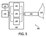
図5は、光源104、光学検出器106及び介入デバイス112を含む分光計102を有する装置の概略的な表示を示す。ここで、介入デバイス112は、例えば光導波路のような光学要素といった1つ又は複数のガイドを持つ。これは、介入デバイスの遠位端部で光を放出するよう、光源104からの光を介入デバイスの遠位端部へと誘導することができ、更に、介入デバイスの遠位端部から戻る光を光学式検出器106へと誘導することができる。光ガイドは、関連付けられる組織サンプル116に光が入ることを可能にし、この光ガイドは更に、関連付けられる組織サンプルを出る光が、光学検出器に集められ及び導かれることを可能にする。この装置はこうして、関連付けられる組織サンプル116の光スペクトルを表す測定データの入手を可能にする。光学検出器106は、測定されたデータを得るよう、プロセッサ110により制御されることができる。プロセッサは、データベース114に対するアクセスを持つことができる。特定の実施形態において、装置はデータベース114にアクセスするよう更に構成される。ここで、このデータベースは、コラーゲン及び/又はエラスチンといった生体分子の光スペクトル、異なる発色団の複数の光スペクトルといった光スペクトルを表す所定のデータを有する。これは、第1のパラメータ、ゆがみパラメータ及び第2のパラメータのいずれか一つをプロセッサがより好適に決定することを可能にすることができる。
FIG. 5 shows a schematic representation of an apparatus having a
特定の図示された実施形態では、第2の光源108も存在する。この実施形態において、第1の光源104は、拡散反射分光学(DRS)に適したランプであり、第2の光源108は、蛍光分光法に適したレーザである。代替的な実施形態において、単一光源だけが存在することができる。これは例えば、放出される周波数の範囲を制限し、これにより帯域幅を狭くし、これにより蛍光分光法を行うのに適切な帯域幅を得るのに役立つ、切り替え可能なフィルタと組み合わせて使用されることができる単一のランプである。
In the particular illustrated embodiment, a second
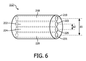
図6は、介入デバイス112の実施形態の斜視図を示す。この介入デバイスは、第1のガイド219、第2のガイド221、第3のガイド223及び第4のガイド225を有する。この図は、第1のガイドの遠位端部にある出口位置219と、第2のガイドの遠位端部にある入力位置221とを示す。同様に、第3のガイドの遠位端部に出口位置223があり、第4のガイドの遠位端部に入力位置225があることが示される。図面は、大きさ通りには描かれていない。第1、第2、第3及び第4のガイドは、光ファイバ、光導波路といった光ガイドであると理解される。更に、第1のガイド218にある出口位置219及び第2のガイド220にある入力位置221の間の距離d1が示される。更に、第3のガイド222にある出口位置223及び第4のガイド224にある入力位置225の間の距離d2が示される。特定の実施形態において、介入デバイスが、拡散反射分光学に関するd1を最適化するよう構築されることができる点に留意されたい。別の特定の実施形態において、介入デバイスは、蛍光分光法に関するd2を最適化するよう構築されることができる。
FIG. 6 shows a perspective view of an embodiment of the
特定の実施形態において、例えば介入デバイス112といった光学プローブが提供される。これは、例えば分光計102といった光学端末に接続されることができる光ファイバ218、220、222、224を持つ針である。光学端末は、光学プローブの遠位端部にファイバの1つを介して光が提供されることを可能にする光源104を含む。散乱された光は、別のファイバにより集められ、検出器106の方へ誘導される。光学端末は、組織サンプルにおける自己蛍光を誘導するため、450nmより低い波長を持つレーザ源108を含むこともできる。例えば測定されたデータの第1及び/又は第2のセットといった得られたデータは、専用のアルゴリズムを用いてプロセッサ110により処理される。例えば、源として機能する少なくとも1つのファイバを通り光は遠位先端から放出され(coupled out of)、波長は例えば500〜1600nmからスイープされるか、又は広帯域光源が使用される。対応する波長依存の反射は、少なくとも1つの他のファイバにより測定され、このファイバは、源から空間的に距離d1離される。この距離は、少なくとも0.5、少なくとも1、少なくとも2mmで、又は少なくとも5mmである。「検出」ファイバで測定される反射光の量は、プローブされる構造(例えば組織サンプル)の吸収及び散乱特性により決定される。この信号から、我々は、例えば血液、水、脂肪、コラーゲン、胆汁、ベータカロチンといった発色団の濃度だけでなく、血液の酸化及び散乱パラメータを演繹することができる。自己蛍光は、励起ファイバのごく近傍に、例えば距離d2内にあるファイバを通り測定される。この距離d2は例えば、5mm未満であり、2mm未満であり、1mm未満であり、0.5mm未満であり、又は0.25mm未満である。測定された自己蛍光は散乱及び吸収に関して修正され、その結果、推定された固有の蛍光が得られる。これから、NADH、FAD、コラーゲン及びエラスチンといった蛍光団の濃度が測定されることができる。
In certain embodiments, an optical probe, such as the
特定の実施形態において、この装置は、組込形シャッタを持つハロゲン広帯域光源の形の光源104、4つのガイドを持つ介入デバイス112、あるスパンの波長にわたり光を分解することができる光学検出器106を有する。あるスパンの波長は例えば、400nmから1700nmまでといった、波長スペクトルの可視及び赤外線領域に実質的にある。この装置は更に、465nm以下の波長に関して光を拒絶するフィルタを有することができる。このフィルタは、拡散反射分光学の間、光学検出器で2次光を拒絶するため、光学検出器106の前に配置されることができる。介入デバイス112は、光源に接続される第1のガイドと、光学検出器106に接続される第2のガイドとを持つ。第1の(放出)ガイド218にある出口位置219と第2の(収集)ガイド220にある出口位置221との間の中心間距離d1は、ミリメートルの範囲にあり、例えば、少なくとも1mm、又は少なくとも2mm、例えば2.48mmとすることができる。すべてのガイドは、ミクロンの範囲におけるコア直径の低OHファイバであり、例えば200ミクロンのコア直径である。VIS―NIRファイバとも呼ばれる低OHを含むファイバは通常、光スペクトルの可視及び(VIS)近赤外線(NIR)部分に適している。
In certain embodiments, the apparatus includes a
代替的な実施形態において、複数の光学検出器が適用される。例えば、異なる長さ領域において、それぞれ実質的に波長スペクトルの可視及び赤外線領域において、例えば400nmから1100nmの、及び800nmから1700nmの光を分解することができる2つの光学検出器である。 In an alternative embodiment, multiple optical detectors are applied. For example, two optical detectors capable of resolving light of, for example, 400 nm to 1100 nm and 800 nm to 1700 nm in different length regions, substantially in the visible and infrared regions of the wavelength spectrum, respectively.
特定の実施形態において、拡散反射分光学が、光スペクトルを表す測定されたデータの第1のセットを得るのに使用され、蛍光分光法が、光スペクトルを表す測定されたデータの第2のセットを得るのに使用される。他の光学的方法も想定されることができる。例えば、蛍光分光法測定、複数の光ファイバを用いることによる拡散光学的断層撮影法、差分経路長分光学、又はラマン分光学である。 In certain embodiments, diffuse reflectance spectroscopy is used to obtain a first set of measured data representing the light spectrum, and fluorescence spectroscopy is used to obtain a second set of measured data representing the light spectrum. Used to get. Other optical methods can also be envisaged. For example, fluorescence spectroscopy measurement, diffusion optical tomography using a plurality of optical fibers, differential path length spectroscopy, or Raman spectroscopy.
好ましくは、光学端末は、蛍光刺激波長が変化されることを可能にする。これは、切替えられるか若しくはマルチプレクス化される(例えば、周波数変調される)複数の源を用いて、又は調整可能な源を用いて実現されることができる。異なる励起波長で異なる蛍光発光スペクトルを測定することは、コラーゲン及びエラスチン(及びさらに異なるタイプのコラーゲン)を識別するのに可能性として重要な情報を提供する。 Preferably, the optical terminal allows the fluorescence stimulation wavelength to be changed. This can be achieved using multiple sources that are switched or multiplexed (eg, frequency modulated), or using adjustable sources. Measuring different fluorescence emission spectra at different excitation wavelengths provides potentially important information for distinguishing collagen and elastin (and even different types of collagen).
2光子蛍光励起が利用されることもできる。これは、1光子励起より深い浸透深さの利益を持つことができる。2光子蛍光測定で探査されるボリュームは、赤外線において拡散反射測定に関して探査されるボリュームに一層類似する場合がある。 Two-photon fluorescence excitation can also be utilized. This can have the advantage of deeper penetration depth than one-photon excitation. The volume probed with two-photon fluorescence measurements may be more similar to the volume probed for diffuse reflectance measurements in the infrared.
器具の前の組織の光学解析を実行するため、3つのステップが実行されなければならない。第1のステップにおいて、分光測定が実行される。光、即ち光学的信号が、器具の遠位端部に送信され、そこで、光は、組織と相互作用する。器具の光ガイドに達する光が再度、分光計に対して誘導される。分光計は、信号をスペクトルに変える。すべてのこれらの要素は、高速な態様の測定に関して時間でおよそ0.2sであり、正確で高い信号対ノイズレベルに関して1s〜2sである。第2のステップにおいて、測定されたスペクトルは、組織パラメータに変換される。このステップは、適合の精度に応じて、速いモードで0.2sから、正確なモードで1s〜3sの間まで変動することができる。第3のステップにおいて、光情報が、撮像デバイス20に送信される。そこでは、データが、器具先端の位置にリンクされ、画像において表示される。
In order to perform an optical analysis of the tissue in front of the instrument, three steps must be performed. In the first step, spectroscopic measurements are performed. Light, an optical signal, is transmitted to the distal end of the instrument, where the light interacts with the tissue. Light reaching the instrument light guide is again directed to the spectrometer. The spectrometer turns the signal into a spectrum. All these factors are approximately 0.2 s in time for fast mode measurements and 1 s to 2 s for accurate and high signal-to-noise levels. In the second step, the measured spectrum is converted into tissue parameters. This step can vary from 0.2 s in fast mode to between 1 s and 3 s in accurate mode, depending on the accuracy of the fit. In the third step, optical information is transmitted to the
生理的パラメータを抽出する代わりに、我々は、第1のモードにおいて特長抽出を行うこともできる。これは、スペクトルが物理モデルにより適合されるのではなく、アルゴリズムが、特定の波長又は複数の別々の波長バンドでのスペクトルにおける変化に基づかれることを意味する。 Instead of extracting physiological parameters, we can also perform feature extraction in the first mode. This means that the spectrum is not fitted by a physical model, but the algorithm is based on changes in the spectrum at a specific wavelength or multiple separate wavelength bands.
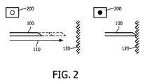
好ましい実施形態において、「速いモード」での光学解析は、器具の速い前進の間、精細な誘導に関して最適化される。これは、選択された組織パラメータの主な変化に関するフィードバックを与え、いつ「正確なモード」での静かな測定に切り替えるかの意志決定を行うための基礎をオペレータに与える。図2を参照されたい。例えば、器具(100)の速い前進(110)の間、速いモードで得られる光学スペクトルは、単純なバイナリ信号(200)に変換されることができる。例えば、組織境界に達したかを示すYes/Noである。これは、X線画像誘導下では可視でない組織境界(120)に対する器具の精細な誘導を可能にする。これは、腫瘍/正常組織、又は切除された/非切除された組織、又は血管の壁の境界を含むことができる。 In a preferred embodiment, optical analysis in “fast mode” is optimized for fine guidance during fast advancement of the instrument. This gives feedback on the main changes in the selected tissue parameters and gives the operator a basis for making a decision when to switch to a quiet measurement in the “accurate mode”. Please refer to FIG. For example, during a fast advance (110) of the instrument (100), the optical spectrum obtained in the fast mode can be converted into a simple binary signal (200). For example, Yes / No indicating whether the organization boundary has been reached. This allows fine guidance of the instrument to the tissue boundary (120) that is not visible under x-ray image guidance. This can include tumor / normal tissue, or resected / non-resected tissue, or blood vessel wall boundaries.
一旦組織境界に達すると、オペレータに対するフィードバックは、音響及び/又は光学信号(200)を有することができる。これにより、これらの信号が、画像ディスプレイ22にリンクされることができる。
Once the tissue boundary is reached, the feedback to the operator can have an acoustic and / or optical signal (200). Thereby, these signals can be linked to the
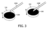
別の実施形態では、器具が固定された位置に配置されるとき、光学端末、即ち組織タイプ決定デバイスの異なる動作モードが使用されることができる。これにより、体の動きが原因による器具先端のターゲット位置からの小さな変位が監視される。例えば、図3を参照し、肺又は心臓の近くの経皮的介入の間、特に、目標が小さいとき、例えば、サイズにおいてわずか2、3ミリメートルの病変のとき、呼吸又は心臓の鼓動が原因の組織運動(310)は、目標(300)から、器具(100A)を変位させることができる。 In another embodiment, different modes of operation of the optical terminal, i.e. the tissue type determination device, can be used when the instrument is placed in a fixed position. This monitors small displacements of the instrument tip from the target position due to body movement. For example, referring to FIG. 3, during percutaneous intervention near the lungs or heart, especially when the target is small, eg, only a few millimeters in size, due to breathing or heart beat Tissue movement (310) can displace instrument (100A) from target (300).
組織タイプ決定デバイスの動作モード(「速い」、「正確」又は更なるモード)は、組織識別の所望の精度と目標での運動の速度との間の最適なバランスを確実にするよう選択されることができる。例えば、光学解析から得られる信号が、組織情報に基づき目標での器具(100A)の位置を検査することを可能にする。これは、必要であれば、医師が位置を精細に調整することを可能にする(100B)。速い光学フィードバックを用いて器具位置を精細に調整することができることは、体における運動に支配される位置で生検を行うのに特に有益である。 The operating mode (“fast”, “accurate” or further mode) of the tissue type determination device is selected to ensure an optimal balance between the desired accuracy of tissue identification and the speed of movement at the target. be able to. For example, the signal obtained from the optical analysis allows the position of the instrument (100A) at the target to be inspected based on the tissue information. This allows the doctor to fine tune the position if necessary (100B). The ability to finely adjust the instrument position using fast optical feedback is particularly beneficial for performing biopsies at motion-dominated positions in the body.
高及び低精度モードを実現する1つの方法は、非常に短い測定時間を使用し、最後のx測定の加重平均を行うことである。加重は、(現在の器具先端位置の最も近くで実行された)ごく最近の測定が、軌道に沿って更に行われる測定より高い重みを持つことを確実にする。この方法を用いると、ゆっくり器具を動かす場合、高い精度を自動的に得ることができ、更に、ほぼ連続的なライン状の測定が得られる。高い精度ボタンは、複数の測定にわたり平均化することにより、結果を改善することができる。平均化することは、自動的に採用されることもできる。例えば、低い血液含有を持つ組織では、信号対ノイズ比は非常に高いので、血液の豊富な組織において必要とされるほど多くの測定にわたり平均化する必要がない。 One way to achieve the high and low accuracy modes is to use a very short measurement time and perform a weighted average of the last x measurement. The weighting ensures that the most recent measurement (performed near the current instrument tip position) has a higher weight than the measurements made further along the trajectory. With this method, a high accuracy can be automatically obtained when moving the instrument slowly, and an almost continuous linear measurement is obtained. High accuracy buttons can improve results by averaging over multiple measurements. Averaging can also be employed automatically. For example, in tissues with low blood content, the signal to noise ratio is so high that it does not need to be averaged over as many measurements as are required in blood rich tissues.
「低精度モード」及び「高精度モード」の間の切り替えを決めるため、我々は、以下の方法を使用することができる。 To determine the switch between “low accuracy mode” and “high accuracy mode”, we can use the following method.
撮像モダリティからの情報(例えば、画像における器具の追跡から、我々は、挿入速度を決めることができ、これが特定の値以下にあるとき、我々は第2のモードを使用する等)。 Information from the imaging modality (eg, from tracking the instrument in the image, we can determine the insertion speed, when this is below a certain value we use the second mode, etc.).
医師の決定。 Doctor's decision.
スペクトルからの情報。 Information from the spectrum.
更に、この決定は、他のパラメータに基づかれることができる。例えば、別の測定モダリティからの情報、電磁追跡、ファイバーブラッグ格子による光学形状センシングに基づかれることができる。FBGは、特定の比較的狭い範囲の波長において光を反射し、他の範囲において光を透過するより長い光ファイバのセグメントである。特定の狭い波長範囲における光の反射は、特定の間隔でファイバーコアの屈折率に周期的変動を加えることにより実現される。これは、波長特有の誘電体ミラーを生み出す。FBGの別の実施形態では、変動が、ファイバの全ての長さに沿って実行されることができる。PercuNavを持つiU22 xMATRIX超音波システムは、電磁気追跡を利用するシステムの例である。 Furthermore, this determination can be based on other parameters. For example, it can be based on information from another measurement modality, electromagnetic tracking, optical shape sensing with a fiber Bragg grating. An FBG is a longer segment of optical fiber that reflects light at certain relatively narrow ranges of wavelengths and transmits light at other ranges. Reflection of light in a specific narrow wavelength range is achieved by adding periodic variations in the refractive index of the fiber core at specific intervals. This creates a wavelength specific dielectric mirror. In another embodiment of the FBG, the variation can be performed along the entire length of the fiber. The iU22 xMATRIX ultrasound system with PercuNav is an example of a system that utilizes electromagnetic tracking.
更に、小型カメラが提供されることができる。これを通して、ファイバが器具挿入の間、誘導される。カメラは、ファイバの動きを介して器具移動を検出することができる。我々はより簡単な移動検出のため、ファイバ上に小さいストライプを加えた。 In addition, a small camera can be provided. Through this, the fiber is guided during instrument insertion. The camera can detect instrument movement via fiber movement. We added a small stripe on the fiber for easier movement detection.
別の実施形態は、器具が加速度計を具備する場合である。加速に関する所定の閾値に基づき、このシステムは、あるモードから別のモードへと切り替える。 Another embodiment is where the instrument comprises an accelerometer. Based on a predetermined threshold for acceleration, the system switches from one mode to another.
更に、誘導システムは、器具の現在の速度を決定する器具速度アナライザを有することができる。もし、現在の器具の速度が速度閾値を超える場合、組織タイプ決定デバイスは第1のモードで作動され、現在の器具の速度が速度閾値以下である場合、組織タイプ決定デバイスは第2のモードで作動される。これは、画像処理デバイスが、2つ又はこれ以上の画像から器具速度を抽出することを可能にする。速度閾値に関して、現在1〜2mmの解像度が、位置において必要とされる。遅いモード又は高い精度モードでは、測定時間及び分析に、約1秒かかる。閾値は、正確なモードが使用されることができる1mm/s未満と選択されることができる。閾値は、ユーザによりセットされる要件に基づき、0.5mm/秒から100mm/秒の範囲とすることができる。現在のところ好ましい閾値は、1mm/秒から20mm/秒の範囲にある。閾値は、システムの入力デバイスを介して、ユーザによりセットされることができる。これにより、システムを用いる人が、その人の好みに基づき、より高い次元へとシステムの処理を制御することが可能にされる。 In addition, the guidance system can have an instrument speed analyzer that determines the current speed of the instrument. If the current instrument speed exceeds the speed threshold, the tissue type determination device is operated in the first mode, and if the current instrument speed is less than or equal to the speed threshold, the tissue type determination device is in the second mode. Actuated. This allows the image processing device to extract instrument speed from two or more images. With respect to the speed threshold, currently a resolution of 1-2 mm is required at the position. In slow or high accuracy mode, the measurement time and analysis takes about 1 second. The threshold can be selected to be less than 1 mm / s where the exact mode can be used. The threshold can range from 0.5 mm / second to 100 mm / second based on the requirements set by the user. The presently preferred threshold is in the range of 1 mm / second to 20 mm / second. The threshold can be set by the user via the input device of the system. This allows a person using the system to control the processing of the system to a higher dimension based on his / her preference.
また、将来、コンピュータの速度が増加し、検出器の感度がより向上することを考慮すれば、低速度は、1sから0.5sへと下がることもあろう。 Also, considering the future increase in computer speed and better detector sensitivity, the low speed may drop from 1 s to 0.5 s.
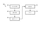
図4は、組織タイプ及び体における器具位置を有する画像を表示する方法44のステップを概略的に示す。方法44は、各時間Tiでの体の内部の画像のシーケンスを記録するステップを有する。方法44は、体の内部の各画像において器具位置を決定するステップを有する。方法44は、時間Ttでの器具の先端での組織パラメータと、時間Ttに近いTiでの器具位置に基づき、推定された器具位置とを決定するステップを含む。方法44は、器具の先端での組織パラメータの決定が、第1の作動モードにおいて第1の算出精度で実行され、器具の先端での組織パラメータの決定が、第2の作動モードにおいて第2の算出精度で実行され、第2の算出精度が、第1の算出精度より高いという、ステップを有する。方法44は、体の内部の現在画像と時間Ttでの器具の先端での組織パラメータの表示との組合せである画像をディスプレイユニットに表示するステップを有する。
FIG. 4 schematically illustrates the steps of a
上述したように、算出精度の適合は、運動の間の組織パラメータの更新を可能にし、任意の所与の時間にて最も可能性のある情報をユーザに提供する。 As described above, the adaptation of the calculation accuracy allows for the updating of tissue parameters during exercise and provides the user with the most likely information at any given time.
本発明が図面及び前述の説明において詳細に図示され及び説明されたが、斯かる図示及び説明は、説明的又は例示的であると考えられ、本発明を限定するものではない。本発明は、開示された実施形態に限定されるものではない。図面、開示及び添付された請求項の研究から、開示された実施形態に対する他の変形が、請求項に記載の本発明を実施する当業者により理解され、実行されることができる。請求項において、単語「有する」は他の要素又はステップを除外するものではなく、不定冠詞「a」又は「an」は複数性を除外するものではない。シングルプロセッサ又は他のユニットが、請求項に記載される複数のアイテムの機能を満たすことができる。特定の手段が相互に異なる従属項に記載されるという単なる事実は、これらの手段の組み合わせが有利に使用されることができないことを意味するものではない。コンピュータープログラムは、他のハードウェアと共に又はその一部として光学的記憶媒体又は固体媒体といった適切な媒体に格納/配布されることができるが、インターネット又は他の有線若しくは無線通信システムを介してといった他の形式で配布されることもできる。請求項における任意の参照符号は、発明の範囲を限定するものとして解釈されるべきではない。 While the invention has been illustrated and described in detail in the drawings and foregoing description, such illustration and description are to be considered illustrative or exemplary and not restrictive. The invention is not limited to the disclosed embodiments. From studying the drawings, disclosure and appended claims, other variations to the disclosed embodiments can be understood and implemented by those skilled in the art practicing the claimed invention. In the claims, the word “comprising” does not exclude other elements or steps, and the indefinite article “a” or “an” does not exclude a plurality. A single processor or other unit may fulfill the functions of several items recited in the claims. The mere fact that certain measures are recited in mutually different dependent claims does not indicate that a combination of these measured cannot be used to advantage. The computer program can be stored / distributed on suitable media, such as optical storage media or solid media, together with or as part of other hardware, but others such as via the Internet or other wired or wireless communication systems. It can also be distributed in the form of Any reference signs in the claims should not be construed as limiting the scope.
Claims (14)
前記体の内部の画像を形成するよう構成される医療撮像デバイスと、
器具から組織信号を受信するよう構成される組織タイプ決定デバイスであって、前記器具からの前記組織信号に基づき、組織パラメータを決定するよう構成される、組織タイプ決定デバイスとを有し、
前記誘導システムは、前記器具の位置を決定し、前記位置を記録するよう構成され、
前記誘導システムが、前記体の内部の画像と前記器具の記録された位置で表示される前記組織パラメータとを組み合わせたディスプレイ画像を確立するよう構成され、
前記誘導システムが更に、前記ディスプレイ画像を表示するよう構成される表示デバイスとを有する、誘導システムにおいて、
前記組織タイプ決定デバイスは、組織タイプ決定が第1の算出精度を用いて実行される第1のモード及び組織タイプ決定が前記第1の算出精度より高い第2の算出精度を用いて実行される第2のモードという2つのモードにおいて動作可能である、誘導システム。 A guidance system for guiding an instrument in the body,
A medical imaging device configured to form an image of the interior of the body;
A tissue type determination device configured to receive a tissue signal from an instrument, wherein the tissue type determination device is configured to determine a tissue parameter based on the tissue signal from the instrument;
The guidance system determines the position of the instrument is configured to record the position,
The guidance system is configured to establish a display image that combines an image of the interior of the body and the tissue parameter displayed at a recorded location of the instrument;
A guidance device further comprising a display device configured to display the display image;
The tissue type determination device performs the first mode in which the tissue type determination is performed using the first calculation accuracy and the second calculation accuracy in which the tissue type determination is higher than the first calculation accuracy. A guidance system operable in two modes, the second mode.
前記誘導システムが、各時間Tiでの前記体の内部の画像のシーケンスを記録するステップと、
前記誘導システムが、前記体の内部の各画像において器具位置を決定するステップと、
前記誘導システムが、時間Ttでの前記器具の先端での組織パラメータと、Ttに近い時間Tiでの前記器具位置に基づき推定された器具位置とを決定するステップであって、
前記器具の先端での組織パラメータの決定が、第1の作動モードにおいて第1の算出精度で実行され、前記器具の先端での組織パラメータの決定が、第2の作動モードにおいて第2の算出精度で実行され、前記第2の算出精度が、前記第1の算出精度より高い、ステップと、
前記誘導システムが、時間Ttでの前記体の内部の現在の画像と、前記器具の先端での組織パラメータの表示との組み合わせである画像をディスプレイユニットに表示するステップとを有する、方法。 In a method of operating a guidance system for displaying an image including a tissue type and an instrument position in a body,
The guidance system recording a sequence of images inside the body at each time Ti;
The guidance system determining an instrument position in each image inside the body;
Said guidance system determining a tissue parameter at the tip of said instrument at time Tt and an estimated instrument position based on said instrument position at time Ti close to Tt, comprising:
Tissue parameter determination at the instrument tip is performed with a first calculation accuracy in a first operating mode, and tissue parameter determination at the instrument tip is a second calculation accuracy in a second operation mode. The second calculation accuracy is higher than the first calculation accuracy, and
The guidance system comprises displaying on the display unit an image that is a combination of a current image of the interior of the body at time Tt and a display of tissue parameters at the tip of the instrument.
各時間Tiでの前記体の内部の画像のシーケンスを記録するステップと、
前記体の内部の各画像において器具位置を決定するステップと、
時間Ttでの前記器具の先端での組織パラメータと、Ttに近い時間Tiでの前記器具位置に基づき推定された器具位置とを決定するステップであって、
前記器具の先端での組織パラメータの決定が、第1の作動モードにおいて第1の算出精度で実行され、前記器具の先端での組織パラメータの決定が、第2の作動モードにおいて第2の算出精度で実行され、前記第2の算出精度が、前記第1の算出精度より高い、ステップと、
時間Ttでの前記体の内部の現在の画像と、前記器具の先端での組織パラメータの表示との組み合わせである画像をディスプレイユニットに表示するステップとを有する、方法。 A software-implemented method executed on a processor for displaying an image including a tissue type and an instrument position in the body, comprising:
Recording a sequence of images inside the body at each time Ti;
Determining an instrument position in each image inside the body;
Determining a tissue parameter at the tip of the instrument at time Tt and an estimated instrument position based on the instrument position at time Ti close to Tt, comprising:
Tissue parameter determination at the instrument tip is performed with a first calculation accuracy in a first operating mode, and tissue parameter determination at the instrument tip is a second calculation accuracy in a second operation mode. The second calculation accuracy is higher than the first calculation accuracy, and
Displaying on the display unit an image that is a combination of a current image inside the body at time Tt and a display of tissue parameters at the tip of the instrument.
Applications Claiming Priority (3)
| Application Number | Priority Date | Filing Date | Title |
|---|---|---|---|
| US201261614558P | 2012-03-23 | 2012-03-23 | |
| US61/614,558 | 2012-03-23 | ||
| PCT/IB2013/051900 WO2013140293A1 (en) | 2012-03-23 | 2013-03-11 | Photonic needle system with measurement integration times depending on needle displacement speed |
Publications (3)
| Publication Number | Publication Date |
|---|---|
| JP2015518384A JP2015518384A (en) | 2015-07-02 |
| JP2015518384A5 JP2015518384A5 (en) | 2016-04-28 |
| JP6232044B2 true JP6232044B2 (en) | 2017-11-15 |
Family
ID=48444438
Family Applications (1)
| Application Number | Title | Priority Date | Filing Date |
|---|---|---|---|
| JP2015501014A Active JP6232044B2 (en) | 2012-03-23 | 2013-03-11 | Photonic needle system using measurement integration time based on needle displacement rate |
Country Status (6)
| Country | Link |
|---|---|
| US (1) | US10383584B2 (en) |
| EP (1) | EP2827792B1 (en) |
| JP (1) | JP6232044B2 (en) |
| CN (1) | CN104244861B (en) |
| RU (1) | RU2014142631A (en) |
| WO (1) | WO2013140293A1 (en) |
Families Citing this family (8)
| Publication number | Priority date | Publication date | Assignee | Title |
|---|---|---|---|---|
| JP6232044B2 (en) | 2012-03-23 | 2017-11-15 | コーニンクレッカ フィリップス エヌ ヴェKoninklijke Philips N.V. | Photonic needle system using measurement integration time based on needle displacement rate |
| EP2884900B1 (en) | 2012-08-17 | 2018-03-07 | Koninklijke Philips N.V. | Camera-based visual adustment of a movable x-ray imaging system |
| CN114795471B (en) | 2015-04-06 | 2026-02-27 | 直观外科手术操作公司 | Systems and methods for registration compensation in image-guided surgery |
| WO2017214599A1 (en) * | 2016-06-11 | 2017-12-14 | Boston Scientific Scimed Inc. | Systems and methods for monitoring tissue ablation using tissue autofluorescence |
| EP3579781B1 (en) | 2017-02-09 | 2020-07-15 | Koninklijke Philips N.V. | Position detection based on tissue discrimination |
| DE102017114077A1 (en) * | 2017-06-26 | 2018-12-27 | Otto-Von-Guericke-Universität Magdeburg | Minimally invasive examination device |
| EP3560415A1 (en) * | 2018-04-24 | 2019-10-30 | Koninklijke Philips N.V. | Tumor margin assessment |
| US11406334B2 (en) | 2018-08-31 | 2022-08-09 | Philips Image Guided Therapy Corporation | Intravascular device movement speed guidance and associated devices, systems, and methods |
Family Cites Families (16)
| Publication number | Priority date | Publication date | Assignee | Title |
|---|---|---|---|---|
| DE69531994T2 (en) * | 1994-09-15 | 2004-07-22 | OEC Medical Systems, Inc., Boston | SYSTEM FOR POSITION DETECTION BY MEANS OF A REFERENCE UNIT ATTACHED TO A PATIENT'S HEAD FOR USE IN THE MEDICAL AREA |
| US6432065B1 (en) | 1999-12-17 | 2002-08-13 | Ethicon Endo-Surgery, Inc. | Method for using a surgical biopsy system with remote control for selecting and operational mode |
| US6766185B2 (en) * | 2000-05-22 | 2004-07-20 | The Board Of Trustees Of The Leland Stanford Junior University | Transmission line techniques for MRI catheter coil miniaturization and tuning |
| CA2533161C (en) | 2003-07-24 | 2013-04-23 | Dune Medical Devices Ltd. | Method and apparatus for examining a substance,particularly tissue, to characterize its type |
| WO2007075091A2 (en) | 2005-12-29 | 2007-07-05 | Rikshospitalet - Radiumhospitalet Hf | Method and apparatus for determining local tissue impedance for positioning of a needle |
| WO2007109540A2 (en) | 2006-03-17 | 2007-09-27 | The General Hospital Corporation | Arrangement, method and computer-accessible medium for identifying characteristics of at least a portion of a blood vessel contained within a tissue using spectral domain low coherence interferometry |
| EP2091416A1 (en) | 2006-12-06 | 2009-08-26 | Koninklijke Philips Electronics N.V. | Obtaining optical tissue properties |
| US20110313299A1 (en) * | 2007-04-30 | 2011-12-22 | Prescient Medical, Inc. | Several measurement modalities in a catheter-based system |
| RU2010130474A (en) | 2007-12-21 | 2012-01-27 | Конинклейке Филипс Электроникс, Н.В. (Nl) | SYNCHRONOUS INTERVENTIONAL SCANNER |
| EP2259716B1 (en) * | 2008-03-03 | 2014-07-02 | Koninklijke Philips N.V. | Biopsy guidance by image-based x-ray guidance system and photonic needle |
| EP2249737B1 (en) | 2008-03-03 | 2020-07-01 | Koninklijke Philips N.V. | Biopsy guidance by electromagnetic tracking and photonic needle |
| WO2010048309A2 (en) | 2008-10-22 | 2010-04-29 | Naviscan, Inc. | A near real-time viewer for pet-guided tissue interventions |
| GB2467340B (en) * | 2009-01-30 | 2013-11-13 | Lein Applied Diagnostics Ltd | Signal sample trigger apparatus, data acquisition system and method of sampling an analogue signal |
| CN102458229B (en) | 2009-06-10 | 2015-07-22 | 皇家飞利浦电子股份有限公司 | Algorithm for photonic needle console |
| US9339348B2 (en) * | 2011-08-20 | 2016-05-17 | Imperial Colege of Science, Technology and Medicine | Devices, systems, and methods for assessing a vessel |
| JP6232044B2 (en) | 2012-03-23 | 2017-11-15 | コーニンクレッカ フィリップス エヌ ヴェKoninklijke Philips N.V. | Photonic needle system using measurement integration time based on needle displacement rate |
-
2013
- 2013-03-11 JP JP2015501014A patent/JP6232044B2/en active Active
- 2013-03-11 US US14/383,716 patent/US10383584B2/en active Active
- 2013-03-11 RU RU2014142631A patent/RU2014142631A/en not_active Application Discontinuation
- 2013-03-11 WO PCT/IB2013/051900 patent/WO2013140293A1/en not_active Ceased
- 2013-03-11 CN CN201380016077.1A patent/CN104244861B/en active Active
- 2013-03-11 EP EP13722821.9A patent/EP2827792B1/en active Active
Also Published As
| Publication number | Publication date |
|---|---|
| EP2827792B1 (en) | 2017-05-10 |
| US20150080711A1 (en) | 2015-03-19 |
| CN104244861B (en) | 2017-09-08 |
| WO2013140293A1 (en) | 2013-09-26 |
| RU2014142631A (en) | 2016-05-20 |
| CN104244861A (en) | 2014-12-24 |
| US10383584B2 (en) | 2019-08-20 |
| EP2827792A1 (en) | 2015-01-28 |
| JP2015518384A (en) | 2015-07-02 |
Similar Documents
| Publication | Publication Date | Title |
|---|---|---|
| JP6232044B2 (en) | Photonic needle system using measurement integration time based on needle displacement rate | |
| JP5658747B2 (en) | Recalibration of recorded images during intervention using a needle device | |
| US11406367B2 (en) | System with photonic biopsy device for obtaining pathological information | |
| JP6734052B2 (en) | Integrated delayed optical feedback in image guidance | |
| US7539530B2 (en) | Method and system for spectral examination of vascular walls through blood during cardiac motion | |
| US20170020460A1 (en) | System and method for assessing a cancer status of biological tissue | |
| US20120101372A1 (en) | Diagnosis support apparatus, diagnosis support method, lesioned part detection apparatus, and lesioned part detection method | |
| EP2805304B1 (en) | Imaging apparatus | |
| JP2011512979A (en) | Image-based X-ray guidance system and biopsy guidance with a light needle | |
| WO2010143119A2 (en) | Algorithm for photonic needle console | |
| US20170273671A1 (en) | Side-looking lung biopsy device | |
| WO2020239974A2 (en) | Intravascular optical device |
Legal Events
| Date | Code | Title | Description |
|---|---|---|---|
| A521 | Request for written amendment filed |
Free format text: JAPANESE INTERMEDIATE CODE: A523 Effective date: 20160310 |
|
| A621 | Written request for application examination |
Free format text: JAPANESE INTERMEDIATE CODE: A621 Effective date: 20160310 |
|
| A977 | Report on retrieval |
Free format text: JAPANESE INTERMEDIATE CODE: A971007 Effective date: 20161221 |
|
| A131 | Notification of reasons for refusal |
Free format text: JAPANESE INTERMEDIATE CODE: A131 Effective date: 20170202 |
|
| RD04 | Notification of resignation of power of attorney |
Free format text: JAPANESE INTERMEDIATE CODE: A7424 Effective date: 20170214 |
|
| A521 | Request for written amendment filed |
Free format text: JAPANESE INTERMEDIATE CODE: A523 Effective date: 20170421 |
|
| TRDD | Decision of grant or rejection written | ||
| A01 | Written decision to grant a patent or to grant a registration (utility model) |
Free format text: JAPANESE INTERMEDIATE CODE: A01 Effective date: 20170928 |
|
| A61 | First payment of annual fees (during grant procedure) |
Free format text: JAPANESE INTERMEDIATE CODE: A61 Effective date: 20171020 |
|
| R150 | Certificate of patent or registration of utility model |
Ref document number: 6232044 Country of ref document: JP Free format text: JAPANESE INTERMEDIATE CODE: R150 |
|
| R250 | Receipt of annual fees |
Free format text: JAPANESE INTERMEDIATE CODE: R250 |
|
| R250 | Receipt of annual fees |
Free format text: JAPANESE INTERMEDIATE CODE: R250 |
|
| R250 | Receipt of annual fees |
Free format text: JAPANESE INTERMEDIATE CODE: R250 |
|
| R250 | Receipt of annual fees |
Free format text: JAPANESE INTERMEDIATE CODE: R250 |
|
| R250 | Receipt of annual fees |
Free format text: JAPANESE INTERMEDIATE CODE: R250 |
|
| R250 | Receipt of annual fees |
Free format text: JAPANESE INTERMEDIATE CODE: R250 |