JP6230121B2 - Blender, beverage production equipment, and mixed liquid production method - Google Patents
Blender, beverage production equipment, and mixed liquid production method Download PDFInfo
- Publication number
- JP6230121B2 JP6230121B2 JP2014066315A JP2014066315A JP6230121B2 JP 6230121 B2 JP6230121 B2 JP 6230121B2 JP 2014066315 A JP2014066315 A JP 2014066315A JP 2014066315 A JP2014066315 A JP 2014066315A JP 6230121 B2 JP6230121 B2 JP 6230121B2
- Authority
- JP
- Japan
- Prior art keywords
- liquid
- tank
- syrup
- concentration
- water
- Prior art date
- Legal status (The legal status is an assumption and is not a legal conclusion. Google has not performed a legal analysis and makes no representation as to the accuracy of the status listed.)
- Active
Links
- 239000007788 liquid Substances 0.000 title claims description 414
- 238000004519 manufacturing process Methods 0.000 title claims description 65
- 235000013361 beverage Nutrition 0.000 title claims description 39
- XLYOFNOQVPJJNP-UHFFFAOYSA-N water Substances O XLYOFNOQVPJJNP-UHFFFAOYSA-N 0.000 claims description 155
- 238000002156 mixing Methods 0.000 claims description 77
- 238000011144 upstream manufacturing Methods 0.000 claims description 61
- 238000000034 method Methods 0.000 claims description 51
- 239000000203 mixture Substances 0.000 claims description 25
- CURLTUGMZLYLDI-UHFFFAOYSA-N Carbon dioxide Chemical compound O=C=O CURLTUGMZLYLDI-UHFFFAOYSA-N 0.000 claims description 16
- 239000011259 mixed solution Substances 0.000 claims description 12
- 238000007599 discharging Methods 0.000 claims description 11
- 238000012805 post-processing Methods 0.000 claims description 10
- 229910002092 carbon dioxide Inorganic materials 0.000 claims description 8
- 239000001569 carbon dioxide Substances 0.000 claims description 8
- 238000003860 storage Methods 0.000 claims description 3
- 241000995051 Brenda Species 0.000 claims 1
- 235000020357 syrup Nutrition 0.000 description 294
- 239000006188 syrup Substances 0.000 description 294
- 238000002360 preparation method Methods 0.000 description 41
- 238000001514 detection method Methods 0.000 description 15
- 238000012545 processing Methods 0.000 description 7
- 239000002994 raw material Substances 0.000 description 5
- 230000001954 sterilising effect Effects 0.000 description 5
- 239000002699 waste material Substances 0.000 description 5
- CZMRCDWAGMRECN-UGDNZRGBSA-N Sucrose Chemical compound O[C@H]1[C@H](O)[C@@H](CO)O[C@@]1(CO)O[C@@H]1[C@H](O)[C@@H](O)[C@H](O)[C@@H](CO)O1 CZMRCDWAGMRECN-UGDNZRGBSA-N 0.000 description 4
- 229930006000 Sucrose Natural products 0.000 description 4
- 238000010790 dilution Methods 0.000 description 4
- 239000012895 dilution Substances 0.000 description 4
- 230000005484 gravity Effects 0.000 description 4
- 238000004659 sterilization and disinfection Methods 0.000 description 4
- 239000005720 sucrose Substances 0.000 description 4
- 238000007664 blowing Methods 0.000 description 3
- 230000007423 decrease Effects 0.000 description 3
- 238000010586 diagram Methods 0.000 description 3
- 230000000844 anti-bacterial effect Effects 0.000 description 2
- 239000007864 aqueous solution Substances 0.000 description 2
- 239000003899 bactericide agent Substances 0.000 description 2
- 238000004140 cleaning Methods 0.000 description 2
- 235000015203 fruit juice Nutrition 0.000 description 2
- 230000004043 responsiveness Effects 0.000 description 2
- 239000011550 stock solution Substances 0.000 description 2
- 238000005406 washing Methods 0.000 description 2
- 230000000903 blocking effect Effects 0.000 description 1
- 238000001816 cooling Methods 0.000 description 1
- 238000007865 diluting Methods 0.000 description 1
- 239000012530 fluid Substances 0.000 description 1
- 230000000717 retained effect Effects 0.000 description 1
- 239000007787 solid Substances 0.000 description 1
- 239000000243 solution Substances 0.000 description 1
- 238000010408 sweeping Methods 0.000 description 1
- 230000002463 transducing effect Effects 0.000 description 1
Images


Landscapes
- Non-Alcoholic Beverages (AREA)
- Accessories For Mixers (AREA)
Description
本発明は、液体を混合するブレンダ、ブレンダを備えた飲料製造設備、および混合液を製造する方法に関する。 The present invention relates to a blender for mixing a liquid, a beverage production facility equipped with a blender, and a method for producing a mixed liquid.
飲料を製造する設備に備えられ、飲料の原材料である濃縮シロップと希釈水とを混合するブレンダが知られている(例えば、特許文献1)。ブレンダにより混合された液体に対して、必要に応じて炭酸ガスの吹き込み等の後工程を行うことにより、飲料が製造される。 A blender that is provided in a facility for producing a beverage and mixes a concentrated syrup, which is a raw material of the beverage, and dilution water is known (for example, Patent Document 1). Beverages are manufactured by performing post-processes, such as blowing of carbon dioxide gas, as necessary for the liquid mixed by the blender.
代表的なブレンダであるGOブレンダ(Gravity Orifice Blender)は、シロップのタンク内の液位と水のタンク内の液位とをそれぞれ一定に制御し、それぞれのタンクから弁を介して所定の流量だけ払い出された液体を混合タンク内で混合する。 A typical blender, GO Blender (Gravity Orifice Blender), controls the liquid level in the tank of syrup and the liquid level in the tank of water, respectively, and only a predetermined flow rate from each tank through a valve. Mix the dispensed liquid in the mixing tank.
飲料製造設備を構成する配管やタンクの内部は定期的に洗浄、殺菌される。その洗浄、殺菌には、熱水や殺菌剤を含む水が使われ、殺菌剤をリンスするのにも水が使われる。 Pipes and tanks that make up beverage production equipment are regularly cleaned and sterilized. For cleaning and sterilization, hot water or water containing a bactericide is used, and water is also used to rinse the bactericide.
洗浄、殺菌後に配管やタンク内から水を抜いたとしても、配管の屈曲部等、配管内には相当量の水が残存する。そういった水がシロップに混入されることで、シロップタンク内のシロップ濃度が規定値よりも低くなったとする。そうすると、シロップタンクと水タンクとから所定流量で払い出された液を混合した際に、混合液の濃度が所定の値を下回ってしまう。 Even if water is drained from the pipe or tank after cleaning and sterilization, a considerable amount of water remains in the pipe, such as a bent part of the pipe. It is assumed that the syrup concentration in the syrup tank is lower than the specified value due to such water being mixed into the syrup. As a result, when the liquid discharged from the syrup tank and the water tank at a predetermined flow rate is mixed, the concentration of the mixed liquid falls below a predetermined value.
それを避けるため、設備の始業に際して例えば10分の間、水が混入したシロップをドレンから排出することが通例である。ドレンからは、当初、配管内に残存している水が排出される。その水は、ある時点から次第にシロップに置き換わる。所定時間、ドレンからシロップと水の混合液を捨てることにより、水からシロップへの置換が完了してから本稼働させるのである。 In order to avoid this, it is customary to discharge the syrup mixed with water from the drain for 10 minutes at the start of the facility. From the drain, water remaining in the pipe is discharged at the beginning. The water gradually replaces the syrup from some point. By discarding the mixed solution of syrup and water from the drain for a predetermined time, the operation from the water to the syrup is completed and the operation is started.
上記では、配管内に残存する水がシロップに完全に置き換わるまでドレンからの排出を行うため、水が混入してはいるものの、混合液の所定の濃度には達しているシロップも捨てられることとなる。そのシロップを捨てることなく製品に利用しようとすれば、供給されるシロップの濃度を連続的に検知し、検知された濃度に応じてシロップと水との混合比率を変更することが考えられる。あるいは混合液の濃度をフィードバックして混合比率を一定に制御することも考えられる。 In the above, since the drainage is performed until the water remaining in the pipe is completely replaced by the syrup, the syrup that has reached the predetermined concentration of the mixed liquid although water is mixed is discarded. Become. In order to use the syrup in a product without throwing it away, it is conceivable to continuously detect the concentration of the supplied syrup and change the mixing ratio of syrup and water according to the detected concentration. Alternatively, the mixing ratio may be controlled to be constant by feeding back the concentration of the mixed solution.
しかし、濃度の検知に要する時間、検知された濃度に応じて制御される弁の動作時間を考慮すると、濃度変化に応答性よく追従することが難しい。そのため、所定の濃度の混合液を得ることが難しい。 However, considering the time required for concentration detection and the valve operation time controlled in accordance with the detected concentration, it is difficult to follow the concentration change with good responsiveness. For this reason, it is difficult to obtain a liquid mixture having a predetermined concentration.
同じことは、始業時に限らず、終業時や運転中にも言え、濃度変化に応答性よく追従することが難しい。 The same is true not only at the start of work, but also at the end of work or during operation, and it is difficult to follow changes in concentration with good responsiveness.
そこで、本発明は、所定の濃度の混合液を得ることができ、それによって原材料の廃棄量を確実に抑えて歩留まりを向上させることができるブレンダ、ブレンダを備えた飲料製造設備、および混合液製造方法を提供することを目的とする。 Therefore, the present invention provides a blender capable of obtaining a liquid mixture having a predetermined concentration, thereby reliably reducing the amount of raw materials discarded and improving the yield, beverage production equipment equipped with the blender, and liquid mixture production It aims to provide a method.
本発明は、第1液体と第2液体とを混合するブレンダであって、第1液体を受け入れて貯留する第1液体タンクと、第2液体を受け入れて貯留する第2液体タンクと、第1液体タンクから払い出される第1液体、および第2液体タンクから払い出される第2液体が混合される混合部と、第1液体タンクの第1液体の濃度を検知するタンク濃度計と、第1液体タンクへと第1液体を導入する導入部を通じた第1液体タンクへの第1液体の受け入れあるいは受入停止を切り替える受入切替弁と、第1液体タンクの第1液体の貯留あるいは払い出しを切り替える払出切替弁と、を備え、導入部に設けられるドレンと、導入部における第1液体の濃度を検知する導入部濃度計と、を備えることを特徴とする。 The present invention is a blender that mixes a first liquid and a second liquid, the first liquid tank that receives and stores the first liquid, the second liquid tank that receives and stores the second liquid, and the first liquid tank. A mixing unit in which the first liquid dispensed from the liquid tank and the second liquid dispensed from the second liquid tank are mixed, a tank concentration meter for detecting the concentration of the first liquid in the first liquid tank, and the first liquid tank A receiving switching valve for switching the first liquid tank to accept or stop receiving the first liquid through the introduction section for introducing the first liquid into the throat, and a dispensing switching valve for switching the storage or dispensing of the first liquid in the first liquid tank And a drain provided in the introduction part, and an introduction part concentration meter for detecting the concentration of the first liquid in the introduction part .
本発明では、第1液体の濃度が、混合液製造の始業時において、第1液体の供給源から供給される第1液体に規定の濃度である規定濃度から低い方向に逸脱した場合に、払出切替弁を閉じたまま、第1液体タンク内に所定の量だけ液を受け入れてから、受入切替弁を閉じることで、第1液体タンク内の液を出入りのない状態とし、その状態で第1液体タンク内の液の濃度をタンク濃度計で検知することができる。そして、検知された濃度に基づいて混合部における第1液体と第2液体との混合比率を設定することができる。 In the present invention, when the concentration of the first liquid, during opening of the mixture produced, deviates from the normal concentration is the concentration specified in the first liquid supplied from a source of the first liquid in the lower direction, payout With the switching valve closed, a predetermined amount of liquid is received in the first liquid tank, and then the receiving switching valve is closed, so that the liquid in the first liquid tank does not go in and out, and the first liquid tank is in that state. The concentration of the liquid in the liquid tank can be detected with a tank concentration meter. And the mixing ratio of the 1st liquid in the mixing part and the 2nd liquid can be set based on the detected density | concentration.
ここで、第1液体タンクに液の出入りがなく安定した状態で、タンク濃度計により第1液体タンク内の液の濃度が正確に検知されるので、検知された濃度に基づいて混合比率を設定することにより、所定の濃度の混合液を確実に得ることができる。 Here, since the concentration of the liquid in the first liquid tank is accurately detected by the tank concentration meter in a stable state with no liquid entering and leaving the first liquid tank, the mixing ratio is set based on the detected concentration. By doing so, a liquid mixture with a predetermined concentration can be obtained reliably.
以上によれば、規定の濃度から逸脱した液を無駄にすることなく製品に利用することができるので、歩留まりを向上させることができる。 According to the above, since the liquid deviating from the prescribed concentration can be used in the product without being wasted, the yield can be improved.
第1液体タンクへの液の受け入れ、第1液体タンクの液濃度の検知、および混合比率の設定は、繰り返し行うことができる。繰り返しの回数は、規定濃度に満たない液の総量と、第1液体タンクの容量とに応じて定まる。 Receipt of the liquid into the first liquid tank, detection of the liquid concentration in the first liquid tank, and setting of the mixing ratio can be performed repeatedly. The number of repetitions is determined according to the total amount of liquid that does not reach the specified concentration and the capacity of the first liquid tank.
タンク濃度計により第1液体の規定の濃度が検知されれば、第1液体タンクおよび第2液体タンクのそれぞれに液を連続して受け入れ、各タンクから払い出された液を混合する連続運転に移行することができる。 When the specified concentration of the first liquid is detected by the tank concentration meter, the liquid is continuously received in each of the first liquid tank and the second liquid tank, and the liquid discharged from each tank is mixed. Can be migrated.
本発明における第1液体は、例えば、シロップや果汁である。 The first liquid in the present invention is, for example, syrup or fruit juice.
本発明における第2液体は、典型的には水である。第2液体はシロップや果汁であってもよい。 The second liquid in the present invention is typically water. The second liquid may be syrup or fruit juice.
第1液体および第2液体に加えて、他の原材料も混合されるように構成することもできる。 In addition to the first liquid and the second liquid, other raw materials can also be mixed.
本発明のブレンダは、導入部に設けられるドレンと、導入部における第1液体の濃度を検知する導入部濃度計と、を備える。 Blender of the present invention, a drain that is provided in the introduction, the introduction portion densitometer for detecting the density of the first liquid in the inlet portion, Ru comprising a.
例えば始業時において、導入部に残存する水から第1液体への置換の開始が検知されるまでの間はドレンから水を排出し、置換の開始が検知されたならば、その後に到来する第1液体を含む液を排出することなく第1液体タンク内に受け入れて製品に利用する。 For example, at the start of work, water is discharged from the drain until the start of replacement of the water remaining in the introduction portion with the first liquid is detected. The liquid containing one liquid is received in the first liquid tank without being discharged and used for the product.
導入部濃度計により水から第1液体への置換開始を捉えたならば即、ドレンからの排出を止めて第1液体タンクへと液を受け入れることにより、第1液体の濃度が混合液の所定濃度以上である限り、第1液体を少しも無駄にすることなく製品に利用することができる。また、第1液体の受け入れ当初より、第1液体を含む液を第1液体タンクに受け入れることができるので、第1液体タンクに定量だけ受け入れて濃度を検知し、混合比率を設定する処理を繰り返す回数を減らすことができる。 As soon as the introduction of the replacement from water to the first liquid is detected by the introduction unit concentration meter, the discharge from the drain is stopped and the liquid is received into the first liquid tank, so that the concentration of the first liquid becomes a predetermined value of the mixed liquid. As long as the concentration is equal to or higher than the concentration, the first liquid can be used in the product without any waste. In addition, since the liquid containing the first liquid can be received in the first liquid tank from the beginning of receiving the first liquid, only the fixed amount is received in the first liquid tank, the concentration is detected, and the process of setting the mixing ratio is repeated. The number of times can be reduced.
本発明のブレンダは、第1液体タンクから払い出される第1液体の流量を定める第1計量弁と、第2液体タンクから払い出される第2液体の流量を定める第2計量弁と、を備え、第1計量弁および第2計量弁の少なくとも一方における流量が変更可能であることが好ましい。 The blender of the present invention includes a first metering valve for determining a flow rate of the first liquid discharged from the first liquid tank, and a second metering valve for determining a flow rate of the second liquid discharged from the second liquid tank, It is preferable that the flow rate in at least one of the first metering valve and the second metering valve can be changed.
第1第1計量弁および第2計量弁の少なくとも一方の開度を変更することなどによって、第1計量弁および第2計量弁の少なくとも一方における流量を変更することにより、混合比率を設定することができる。 Setting the mixing ratio by changing the flow rate in at least one of the first metering valve and the second metering valve, such as by changing the opening of at least one of the first first metering valve and the second metering valve. Can do.
本発明のブレンダは、タンク濃度計により検知された濃度に基づいて第1計量弁および第2計量弁の少なくとも一方の開度を取得する開度取得部を備えることが好ましい。 The blender of the present invention preferably includes an opening degree obtaining unit that obtains an opening degree of at least one of the first metering valve and the second metering valve based on the concentration detected by the tank densitometer.
開度取得部により、弁開度を自動的に、容易に取得することができる。 The valve opening can be automatically and easily acquired by the opening acquiring unit.
本発明のブレンダにおいて、第1液体タンクは、導入部により第1液体が導入される上流タンクと、上流タンクの下流側に連結される下流タンクとを含んで構成され、上流タンクは、下流タンクに比べて貯留可能な量が大であり、タンク濃度計は、上流タンクの第1液体の濃度を検知し、受入切替弁は、上流タンクへの第1液体の受け入れあるいは受入停止を切り替え、払出切替弁は、上流タンクの第1液体の貯留あるいは払い出しを切り替えることが好ましい。 In the blender of the present invention, the first liquid tank includes an upstream tank into which the first liquid is introduced by the introduction portion, and a downstream tank connected to the downstream side of the upstream tank, and the upstream tank is a downstream tank. The tank concentration meter detects the concentration of the first liquid in the upstream tank, and the acceptance switching valve switches between accepting or stopping acceptance of the first liquid in the upstream tank, and dispensing it. The switching valve preferably switches between storing and discharging the first liquid in the upstream tank.
上記の構成では、第1液体の受け入れを上流タンクに、第1液体の払い出しを下流タンクに分担させる。 In the above configuration, the reception of the first liquid is shared by the upstream tank, and the discharge of the first liquid is shared by the downstream tank.
そうすると、上流タンク内に液を受け入れてタンク濃度計により濃度を検知し、その検知濃度に基づいて下流タンクの液と第2液体タンクの液との混合比率を割り出すことができる。それを終えたら、上流タンクから下流タンクへと液を移送して、設定した混合比率で液の混合を行う。 Then, the liquid is received in the upstream tank, the concentration is detected by the tank densitometer, and the mixing ratio of the liquid in the downstream tank and the liquid in the second liquid tank can be determined based on the detected concentration. After that, the liquid is transferred from the upstream tank to the downstream tank, and the liquid is mixed at the set mixing ratio.
ここで、上流タンクの貯留可能な量(容量)が下流タンクに比べて大であることにより、液の受け入れおよび液の払い出しの双方を下流タンクが担う場合と比べて、液受け入れ、濃度検知、混合比率設定の処理が繰り返される回数を少なくすることができる。 Here, since the amount (capacity) that can be stored in the upstream tank is larger than that in the downstream tank, compared with the case where the downstream tank takes both liquid reception and liquid discharge, liquid reception, concentration detection, The number of times the mixing ratio setting process is repeated can be reduced.
そのため、繰り返される処理の次のサイクルに移る前に、一旦液の受け入れを停止する操作や、計器等の動作確認などに要する手間を低減できる。 Therefore, it is possible to reduce time and effort required for temporarily stopping the reception of the liquid and confirming the operation of the instrument and the like before moving on to the next cycle of the repeated processing.
上記構成において、上流タンクの第1液体を循環させる循環経路を備え、タンク濃度計は、循環経路を流れる第1液体の濃度を検知することが好ましい。 In the above configuration, it is preferable that a circulation path for circulating the first liquid in the upstream tank is provided, and the tank concentration meter detects the concentration of the first liquid flowing in the circulation path.
その場合、タンク濃度計として、配管に設置可能な汎用の濃度計を用いることができる。 In that case, a general-purpose concentration meter that can be installed in the pipe can be used as the tank concentration meter.
本発明の飲料製造設備は、上述のブレンダと、ブレンダにより混合された混合液を容器に充填する、あるいは、混合液に炭酸ガスを吹き込む後工程装置と、を備える、ことを特徴とする。 The beverage production facility of the present invention is characterized by comprising the blender described above and a post-process device that fills a container with the mixed liquid mixed by the blender or blows carbon dioxide into the mixed liquid .
本発明の飲料製造設備は、ブレンダから後工程装置へと混合液を送り出す送出経路に、送出経路濃度計を備えることが好ましい。 The beverage production facility of the present invention preferably includes a delivery path densitometer on the delivery path for sending the mixed solution from the blender to the post-processing apparatus.
送出経路濃度計による濃度に基づいて、送出経路に残存する水と液との置換状況を検知することができる。それにより、後工程においても、液を無駄なく使用して歩留まりを向上させることが可能となる。 Based on the concentration by the delivery path densitometer, it is possible to detect the replacement status of water and liquid remaining in the delivery path. As a result, the yield can be improved by using the liquid without waste even in the post-process.
本発明の混合液製造方法は、第1液体と第2液体とを混合して混合液体を製造する方法であって、第1液体を所定の量だけ第1液体タンクに受け入れる第1ステップと、第1液体タンクの第1液体の濃度を検知する第2ステップと、検知された濃度に基づいて、第1液体タンクから払い出される第1液体と、第2液体との混合比率を設定する第3ステップと、混合比率にて第1液体および第2液体を混合する第4ステップと、を含むことを特徴とする。
また、本発明の混合液製造方法は、上述のブレンダを使用した混合液製造方法としても特定できる。
つまり、本発明の混合液製造方法は、以下の構成のブレンダを使用する。
第1液体と第2液体とを混合するブレンダであって、第1液体を受け入れて貯留する第1液体タンクと、第2液体を受け入れて貯留する第2液体タンクと、第1液体タンクから払い出される第1液体、および第2液体タンクから払い出される第2液体が混合される混合部と、第1液体タンクの第1液体の濃度を検知するタンク濃度計と、第1液体タンクへと第1液体を導入する導入部を通じた第1液体タンクへの第1液体の受け入れあるいは受入停止を切り替える受入切替弁と、第1液体タンクの第1液体の貯留あるいは払い出しを切り替える払出切替弁と、導入部に設けられるドレンと、導入部における第1液体の濃度を検知する導入部濃度計と、を備えたブレンダ。
このブレンダを使用する場合、本発明の混合液製造方法は、受入切替弁を用いて、導入部を通じ、第1液体を所定の量だけ第1液体タンクに受け入れる第1ステップと、タンク濃度計を用いて第1液体タンクの第1液体の濃度を検知する第2ステップと、検知された濃度に基づいて、払出切替弁を用いて第1液体タンクから払い出される第1液体と、第2液体タンクから払い出される第2液体との混合比率を設定する第3ステップと、混合比率にて第1液体および第2液体を混合部において混合する第4ステップと、を含むことを特徴とする。
The mixed liquid production method of the present invention is a method for producing a mixed liquid by mixing a first liquid and a second liquid, wherein the first liquid is received in a first liquid tank by a predetermined amount; A second step of detecting the concentration of the first liquid in the first liquid tank; and a third step of setting a mixing ratio of the first liquid dispensed from the first liquid tank and the second liquid based on the detected concentration. And a fourth step of mixing the first liquid and the second liquid at a mixing ratio.
Moreover, the liquid mixture manufacturing method of this invention can be specified also as a liquid mixture manufacturing method using the above-mentioned blender.
That is, the blended liquid manufacturing method of the present invention uses a blender having the following configuration.
A blender for mixing the first liquid and the second liquid, the first liquid tank for receiving and storing the first liquid, the second liquid tank for receiving and storing the second liquid, and the first liquid tank being dispensed. The first liquid to be mixed with the first liquid and the second liquid dispensed from the second liquid tank, the tank concentration meter for detecting the concentration of the first liquid in the first liquid tank, and the first liquid tank. An acceptance switching valve that switches between receiving and stopping the reception of the first liquid into the first liquid tank through the introducing section that introduces liquid, a dispensing switching valve that switches between storing and dispensing the first liquid in the first liquid tank, and an introducing section A blender comprising: a drain provided in the inlet; and an inlet concentration meter that detects the concentration of the first liquid in the inlet.
When this blender is used, the mixed liquid manufacturing method of the present invention includes a first step of receiving a predetermined amount of the first liquid into the first liquid tank through the introduction section using the acceptance switching valve, and a tank densitometer. A second step of detecting the concentration of the first liquid in the first liquid tank, a first liquid discharged from the first liquid tank using the discharge switching valve based on the detected concentration, and a second liquid tank A third step of setting a mixing ratio with the second liquid dispensed from the first and a fourth step of mixing the first liquid and the second liquid in the mixing unit at the mixing ratio.
本発明によれば、第1液体の濃度が規定の濃度から逸脱した際に、第1ステップにより第1液体タンク内に所定の量だけ貯留された液の濃度を、第2ステップにより検知することができる。そして、検知された濃度に基づいて第1液体と第2液体との混合比率を設定することができる(第3ステップ)。 According to the present invention, when the concentration of the first liquid deviates from the prescribed concentration, the second step detects the concentration of the liquid stored in the first liquid tank by a predetermined amount in the first step. Can do. Then, the mixing ratio of the first liquid and the second liquid can be set based on the detected concentration (third step).
ここで、第1液体タンクに液の出入りがなく安定した状態で、第1液体タンク内の液の濃度が正確に検知されるので、検知された濃度に基づいて混合比率を設定することにより、所定の濃度の混合液を確実に得ることができる(第4ステップ)。 Here, since the concentration of the liquid in the first liquid tank is accurately detected in a stable state with no liquid entering and leaving the first liquid tank, by setting the mixing ratio based on the detected concentration, A liquid mixture having a predetermined concentration can be obtained reliably (fourth step).
以上によれば、規定の濃度から逸脱した液を無駄にすることなく製品に利用することができるので、歩留まりを向上させることができる。 According to the above, since the liquid deviating from the prescribed concentration can be used in the product without being wasted, the yield can be improved.
本発明の混合液製造方法においては、第1液体タンクへと第1液体を導入する導入部の内部に存在する水を第1液体で置換する際に、第1ステップから第4ステップまでを行うことができる。 In the mixed liquid manufacturing method of the present invention, the first step to the fourth step are performed when the water present in the introduction portion for introducing the first liquid into the first liquid tank is replaced with the first liquid. be able to.
上記構成において、第1ステップから第4ステップまでを行う前に、第1液体タンクへと第1液体を導入する導入部の液濃度の上昇が導入部濃度計により検知されるまで水をドレンから排出するステップを含むことが好ましい。 In the above configuration, before performing the first step to the fourth step, water is drained from the drain until an increase in the liquid concentration of the introduction unit that introduces the first liquid into the first liquid tank is detected by the introduction unit concentration meter. Preferably, the method includes a discharging step.
導入部の液濃度が上昇することをもって、導入部に存在する水から第1液体への置換開始が捉えられるので、後続の第1液体を含む液を排出することなく第1液体タンク内に受け入れて製品に利用することができる。 As the liquid concentration in the introduction part rises, the start of replacement of the water present in the introduction part with the first liquid is caught, so that the liquid containing the subsequent first liquid is received in the first liquid tank without being discharged. Can be used for products.
導入部の液濃度の上昇は、例えば、導入部内の検知された液濃度が所定の閾値以上となったことに基づいて検知することができる。 An increase in the liquid concentration in the introduction unit can be detected based on, for example, that the detected liquid concentration in the introduction unit has reached a predetermined threshold value or more.
水から第1液体への置換が開始された直後を捉えるために、閾値は0に近い値に設定されることが好ましい。そうるすと、導入部の液濃度が少しでも上昇したならば即、ドレンからの排出を止めて第1液体タンクへの受け入れに移行することができる。 In order to capture immediately after the replacement of water with the first liquid is started, the threshold value is preferably set to a value close to zero. If it does so, if the liquid density | concentration of an introducing | transducing part raises even a little, it will be immediately possible to stop discharge | emission from a drain and to transfer to reception to a 1st liquid tank.
なお、液濃度の上昇率が所定の閾値以上となったことに基づいて、導入部の液濃度の上昇を検知することもできる。 It should be noted that an increase in the liquid concentration in the introduction portion can be detected based on the increase rate in the liquid concentration being equal to or greater than a predetermined threshold value.
本発明の混合液製造方法においては、第1液体タンクへと第1液体を導入する導入部の内部に存在する第1液体を水で置換する際、第1ステップから第4ステップまでを行うことができる。 In the mixed liquid manufacturing method of the present invention, when replacing the first liquid existing in the introduction part for introducing the first liquid into the first liquid tank with water, the first step to the fourth step are performed. Can do.
上記構成において、第1液体タンクへと第1液体を導入する導入部の液濃度の下降が導入部濃度計により検知されるまで、第1ステップから第4ステップまでを行うことが好ましい。 In the above configuration, it is preferable to perform the first step to the fourth step until a decrease in the liquid concentration of the introduction part that introduces the first liquid into the first liquid tank is detected by the introduction part concentration meter .
本発明の混合液製造方法においては、第1液体タンクへと導入される第1液体の濃度の変化が生じた際に、第1ステップから第4ステップまでを行うことができる。 In the mixed liquid manufacturing method of the present invention, the first step to the fourth step can be performed when the concentration of the first liquid introduced into the first liquid tank changes.
本発明の混合液製造方法において、第3ステップでは、第1液体タンクから払い出される第1液体の流量、および第2液体の流量に基づいて混合比率を設定することができる。 In the mixed liquid manufacturing method of the present invention, in the third step, the mixing ratio can be set based on the flow rate of the first liquid discharged from the first liquid tank and the flow rate of the second liquid.
本発明の混合液製造方法において、第1液体タンクから払い出される第1液体の流量よりも、第2液体の流量が大であり、第2液体の流量を一定とし、第1液体タンクから払い出される第1液体の流量を可変に制御することで混合比率を設定することが好ましい。 In the mixed liquid manufacturing method of the present invention, the flow rate of the second liquid is larger than the flow rate of the first liquid discharged from the first liquid tank, the flow rate of the second liquid is constant, and the flow rate is discharged from the first liquid tank. It is preferable to set the mixing ratio by variably controlling the flow rate of the first liquid.
第2液体に比べて流量が小さい第1液体の流量を変更することで、全体的な流れにさほど影響を与えることなく、所定の濃度の混合液を得ることができる。 By changing the flow rate of the first liquid whose flow rate is smaller than that of the second liquid, it is possible to obtain a liquid mixture having a predetermined concentration without significantly affecting the overall flow.
本発明によれば、所定の濃度の混合液を得ることができ、それによって原材料の廃棄量を確実に抑えて歩留まりを向上させることができる。 According to the present invention, it is possible to obtain a liquid mixture having a predetermined concentration, thereby reliably reducing the amount of raw materials discarded and improving the yield.
以下、添付図面を参照しながら、本発明の実施形態について説明する。
〔第1実施形態〕
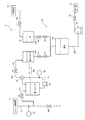
図1に示す飲料製造装置1は、原材料であるシロップおよび水から飲料を製造する。
飲料製造装置1は、シロップ供給源11と、水供給源12と、シロップと水とを混合するブレンダ20と、ブレンダ20にシロップを導入するための導入経路13と、導入経路13に設けられるドレン14と、ブレンダ20により混合された液に対して冷却、炭酸ガスの吹き込み、容器への充填等の後工程を行う後工程装置15と、ブレンダ20により作られた混合液を後工程装置15に向けて送り出す送液ポンプ16とを備える。
飲料製造設備1を構成する各要素同士は、配管により接続される。
Hereinafter, embodiments of the present invention will be described with reference to the accompanying drawings.
[First Embodiment]
A beverage production apparatus 1 shown in FIG. 1 produces a beverage from syrup and water as raw materials.
The beverage production apparatus 1 includes a
Each element which comprises the drink manufacturing equipment 1 is connected by piping.
導入経路13は、シロップ供給源11とブレンダ20のシロップタンク21とを接続する。
ドレン14は、導入経路13内に残存する水をシロップタンク21へと送ることなく、図示しないタンクへと排出させる。ドレン14は、ドレン弁141の操作により開閉される。
The
The
ブレンダ20は、シロップタンク21と、水タンク22と、シロップ計量弁23と、水計量弁24と、混合タンク25とを備える。
シロップタンク21は、シロップ供給源11から供給されたシロップを貯留する。
シロップ供給源11とシロップタンク21との間には、シロップタンク21へのシロップの受け入れを許容する場合(開)と、遮断する場合(閉)とに切り替えられるシロップ受入切替弁17が設けられる。
水タンク22は、シロップを希釈するために水供給源12から供給された水を貯留する。
水供給源12と水タンク22との間には、水タンク22への水の供給を許容する場合(開)と、遮断する場合(閉)とに切り替えられる水受入切替弁18が設けられる。
The
The
Between the
The
Between the
ブレンダ20は、GOブレンダであり、シロップタンク21内の液位と水タンク22内の液位とをそれぞれ一定に制御し、それぞれのタンク21,22から計量弁23,24を介して所定の流量だけ払い出されたシロップと水とを混合タンク25内で混合する。
本実施形態では、シロップの流量に比べて水の流量の方が大きい。シロップと水とは、例えば、1:4の割合で混合される。
なお、シロップと水とを1:1の割合で混合することもできる。
The
In this embodiment, the flow rate of water is larger than the flow rate of syrup. Syrup and water are mixed in a ratio of 1: 4, for example.
In addition, syrup and water can also be mixed in the ratio of 1: 1.
シロップタンク21には、貯留した液を重力により混合タンク25内へと払い出すための払出経路210が接続される。
水タンク22には、貯留した水を重力により混合タンク25内へと払い出すための払出経路220が接続される。
なお、シロップタンク21および水タンク22のそれぞれの液の払い出しには、重力のみならず圧力も加担する。
シロップの払出経路210に位置するシロップ計量弁23は、開度が可変であり、設定された開度に応じた所定の流量でシロップを通過させる。
払出経路210においてシロップ計量弁23の前段には、シロップタンク21内に液を貯留する場合(閉)と、シロップタンク21内から液を払い出す場合(開)とに切り替えられるシロップ払出切替弁27が設けられる。
ここで、シロップ払出切替弁27およびシロップ計量弁23を一体の弁として構成することもできる。つまり、シロップ払出切替弁27およびシロップ計量弁23を設ける代わりに、シロップを計量するとともに、シロップの貯留/払い出しを切り替える弁を設けることができる。
The
The
Note that not only gravity but also pressure is applied to the dispensing of the liquid from the
The
In the
Here, the syrup
水の払出経路210に位置する水計量弁24は、開度が可変であり、設定された開度に応じた所定の流量で水を通過させる。
払出経路220において水計量弁24の前段には、水タンク22内に液を貯留する場合(閉)と、水タンク22内から液を払い出す場合(開)とに切り替えられる水払出切替弁28が設けられる。
ここで、水払出切替弁28および水計量弁24を一体の弁として構成することもできる。つまり、水払出切替弁28および水計量弁24を設ける代わりに、水を計量するとともに、水の貯留/払い出しを切り替える弁を設けることができる。
The
In the
Here, the water
シロップ受入切替弁17、水受入切替弁18、シロップ払出切替弁27、および水払出切替弁28は、原則、ブレンダ20の起動/停止に連動される。
つまり、ブレンダ20が起動されると、これらの弁17,18,27,28は開いた状態に切り替えられ、ブレンダ20が停止されると、これらの弁17,18,27,28は閉じた状態に切り替えられる。
In principle, the syrup
That is, when the
混合タンク25は、シロップタンク21および水タンク22内からそれぞれ払い出されて混合された液を貯留する。
混合タンク25には、貯留した液を下流側へと払い出すための払出経路250が接続される。
混合タンク25と後工程装置15との間(本実施形態では送液ポンプ16と後工程装置15との間)には、混合タンク25内に液を貯留する場合(閉)と、混合タンク25内から液を払い出す場合(開)とに切り替えられる払出切替弁29が設けられる。
The mixing
A
When the liquid is stored in the mixing tank 25 (closed) between the mixing
本実施形態の飲料製造設備1は、製品である飲料を一定の濃度で製造する。
本実施形態における濃度は、ブリックス(Brix)を意味する。ブリックスとは、液体中の可溶性固体の重量含有率のことをいう。シロップ(ショ糖水溶液)におけるブリックスは、ショ糖水溶液の単位重量(例えば100g)に含まれるショ糖の重量をいう。
シロップ供給源11から供給されるシロップ(原液)は、規定の濃度(ブリックス)を示す。この原液シロップに、飲料製造設備1の洗浄、殺菌等に用いられた後そのまま導入経路13内に残存する水が混入することで、規定の濃度よりも低い濃度のシロップがシロップタンク21に導入されることがある。しかし、そのシロップの濃度が製品に定められるショ糖の濃度(製品濃度)以上であれば、原液の規定濃度よりは低くても製品に利用可能である。
The beverage production facility 1 of the present embodiment produces a beverage that is a product at a constant concentration.
The concentration in the present embodiment means Brix. Brix refers to the weight content of soluble solids in a liquid. Brix in syrup (sucrose aqueous solution) refers to the weight of sucrose contained in a unit weight (for example, 100 g) of the sucrose aqueous solution.
The syrup (stock solution) supplied from the
本実施形態の飲料製造設備1は、シロップを無駄なく製品に利用するために、シロップの濃度(ブリックス)を検知する第1ブリックス計31および第2ブリックス計32を備える。
第1ブリックス計31は、導入経路13内を流れる液のブリックスを検知する。
第2ブリックス計32は、シロップタンク21内に貯留された液のブリックスを検知する。
これらのブリックス計31,32としては、液の屈折率あるいは密度の測定値に基づいてブリックスを算出するものを用いることができる。
本実施形態において、単に「液」と言う場合は、場所や、水およびシロップの置換状況に応じて、シロップ、シロップおよび水の混合液、および水のうちのいずれかを意味する。
The beverage production facility 1 of the present embodiment includes a
The
The
As these
In the present embodiment, the term “liquid” simply means any one of syrup, a mixed solution of syrup and water, and water depending on the place and the replacement status of water and syrup.
以下、第1ブリックス計31および第2ブリックス計32が示す値を適宜参照して行う飲料製造設備1の始業に際して行われる処理(図2)について説明する。
Hereinafter, the process (FIG. 2) performed at the time of the start of the beverage manufacturing equipment 1 performed by referring to the values indicated by the
[始業処理]
始業に際して、第1始業準備段階S10および第2始業準備段階S20を行う。
始業前において、飲料製造設備1の配管内やタンク内には、飲料製造設備1の洗浄、あるいは殺菌のすすぎに用いられた清浄な水が存在する。
飲料を製造するにあたり、ドレン弁141を開くことでドレン14からの水の排出を開始するとともに、ブレンダ20を起動し、シロップ供給源11からシロップタンク21へのシロップの受け入れを開始する(ステップS11)。
ブレンダ20は、シロップタンク21および水タンク22のそれぞれの液位を一定に制御しながら、計量弁23,24の開度に従った流量でシロップおよび水を混合タンク25内へと払い出して混合する。
[Starting process]
At the start of work, a first start-up preparation stage S10 and a second start-up preparation stage S20 are performed.
Before the start of work, clean water used for washing or sterilizing the beverage production facility 1 is present in the pipes and tanks of the beverage production facility 1.
In manufacturing the beverage, the
The
ブレンダ20の運転中、シロップ供給源11から供給されるシロップは、導入経路13、シロップタンク21、混合タンク25、および後工程装置15へと順次、水を追い込みながら下流へと送られる。
したがって、供給されたシロップが導入経路13における第1ブリックス計31の検知箇所に到達するまでは、第1ブリックス計31は0に近い値を検知する。第1ブリックス計31により閾値以上の値が検知されるまでの間は(ステップS12でY)、ドレン14からの水の排出を続ける。
During the operation of the
Therefore, the
シロップ供給源11から供給されたシロップの流れは、水と置換されながら導入経路13内を進む。少量のシロップを含む液が第1ブリックス計31による検知箇所に到達すると、第1ブリックス計31により、0を超えた所定の閾値以上の濃度が検知される(ステップS12でY)。
つまり、検知箇所では水と同視しうる状態を脱してシロップへの置換が開始されたことが検知されたことになる。後続の液にはシロップが含まれる。
本実施形態では、次の第2始業準備段階S20において、その液に含まれるシロップを捨てることなく製品に利用する。
The flow of syrup supplied from the
In other words, it has been detected that the replacement with the syrup is started at the detection location while leaving the state that can be equated with water. Subsequent liquids contain syrup.
In the present embodiment, in the next second start-up preparation stage S20, the syrup contained in the liquid is used in the product without being discarded.
そのため、導入経路13のドレン弁141を閉じて液の排出を停止する(ステップS13)。
ステップS13では、シロップ受入切替弁17を閉じてシロップタンク21へのシロップの受け入れを停止しておく。
水の排出を完了したら、一旦、ブレンダ20を停止する。
Therefore, the
In step S13, the syrup
When the discharge of water is completed, the
次いで、第2始業準備段階S20に移行する。
第2始業準備段階S20に移行する前までに、シロップタンク21および混合タンク25のそれぞれの液を排出させておく。
第2始業準備段階S20では、まず、シロップ受入切替弁17を開き、シロップタンク21内の規定の液位までシロップを受け入れたら、シロップ受入切替弁17を再び閉じて受け入れを停止する(ステップS21)。
そして、シロップタンク21内に貯留された液の濃度を第2ブリックス計32によって検知する(ステップS22)。
ここで、受け入れ開始直後は、依然として水に近い状態の液がシロップタンク21へと流入するが、継続して流入する液がシロップタンク21内に貯留される過程で、シロップタンク21内の液の濃度は上昇する。シロップタンク21内に貯留された液の濃度が、シロップタンク21内に供給されるシロップの規定濃度(シロップ供給源11と同様)には満たなくても、製品濃度には達しているのであれば、その液と、希釈する水との混合比率を変更することで、シロップタンク21内の液を製品に利用可能である。
Next, the process proceeds to the second start-up preparation stage S20.
The liquids in the
In the second start-up preparation stage S20, first, the syrup
Then, the concentration of the liquid stored in the
Here, immediately after the start of acceptance, the liquid in a state close to water still flows into the
そのため、第2ブリックス計32により検知されたシロップタンク21内の液の濃度に基づいて、希釈水と混合したときに所定の製品濃度を得ることのできるシロップ計量弁23の開度を算出する(ステップS23)。
つまり、シロップタンク21内の液の濃度が規定よりも薄いので、シロップ計量弁23の開度を大きくすることによって、混合タンク25内に送られるシロップを水に対して増量する。ここで、水に比べて流量が小さいシロップの計量弁23の開度を変えることで、飲料製造設備1内の全体の流れにさほど影響を与えることなく、所定の製品濃度の混合液を作ることができる。
シロップ計量弁23の開度は、第2ブリックス計32により検知された濃度に応じて自動的に演算を行う演算部34によって算出することもできる。
Therefore, based on the concentration of the liquid in the
That is, since the concentration of the liquid in the
The opening degree of the
製品濃度を得るために必要な開度が算出されたならば、その開度でシロップ計量弁23を設定する(ステップS24)。
If the opening required to obtain the product concentration is calculated, the
次いで、ブレンダ20を起動して、シロップタンク21内の液と水タンク22内の水とをそれぞれ払い出しながら混合タンク25内でブレンドする(ステップS25)。その間は、シロップ受入切替弁17を閉じたままシロップの受け入れをしない。このときブレンダ20は、シロップタンク21内の液位を一定に制御することを行わない。
シロップと異なり濃度変化のない水は、ステップS21においてシロップをシロップタンク21に所定の液位まで受け入れるまでに、水タンク22に所定の液位まで受け入れておく。以降は、ブレンダ20の運転に伴って、水受入切替弁18、水払出切替弁28、および水計量弁24が制御されることで、水タンク22内の水位が一定に保たれることとなる。
Next, the
Unlike syrup, water having no change in concentration is received in the
シロップタンク21内の液の払い出しが完了すると(ステップS26)、混合タンク25内には、所定の製品濃度の混合液が貯留されているので、混合液を後工程装置15に送ることで、製品に利用することができる。
When the dispensing of the liquid in the
その後は、上記のステップS21に戻り、ステップS21〜S26を繰り返す。なお、ステップS26を終えた後、ブレンダ20を一旦停止し、各種の弁やブリックス計31,32の状態を確認してからステップS21に戻ってもよい。
ステップS21〜S26を繰り返した回数の分だけ、混合タンク25内に製品濃度の混合液が作られるので、その都度、混合タンク25内から後工程装置15へと払い出して、製品に利用する。
After that, it returns to said step S21 and repeats step S21-S26. In addition, after finishing step S26, the
Since a liquid mixture having a product concentration is produced in the
ステップS21〜S26を2回以上繰り返すうち、水からシロップへの置換が完全に終了した後は、シロップタンク21内には、水が混入していないシロップが貯留される。それによって、ステップS22で、第2ブリックス計32により規定濃度(あるいは規定濃度の許容範囲の値)が検知されれば(ステップS22でY)、第2始業準備段階S20を終了する。
While the steps S21 to S26 are repeated two or more times, after the replacement of water with syrup is completed, syrup in which no water is mixed is stored in the
以上で始業準備を終えたならば、通常の製造工程に移行する。このとき、シロップタンク21内に規定の液位まで貯留されている規定濃度のシロップをそのまま使用する。
シロップ受入切替弁17を開いてシロップの受け入れを再開し、シロップタンク21と水タンク22のそれぞれの液位を一定に保つ通常のモードでブレンダ20を運転させることにより、シロップと水とを連続的に混合して飲料を製造することができる。
After completing the start-up preparation, the process shifts to a normal manufacturing process. At this time, the syrup having the specified concentration stored in the
The syrup
以上で説明したように、本実施形態では、第1ブリックス計31により検知された濃度に基づいて導入経路13内の水からシロップへの置換の開始が検知されると、その後に続く液を捨てることなくシロップタンク21内に受け入れて製品に利用するので、歩留まりを向上させることができる。
ここで、シロップを含む液を利用するにあたり、シロップタンク21内に液を定量だけ受け入れて貯留している。そのため、シロップの出入りがなく安定した状態で、第2ブリックス計32によりシロップタンク21内の液の濃度が正確に検知される。したがって、検知されたシロップタンク21内の液の濃度が製品濃度以上である限り、検知された濃度に基づいてシロップと水との混合比率を変更することで、所定の製品濃度である混合液を確実に得ることができる。このとき、混合タンク25内で混合される水の量とシロップの量とを所定の混合比率に合致させることができる限り、シロップおよび水のそれぞれの払い出しのタイミングや流量は任意である。水の量とシロップの量とを所定の混合比率に合致させるために、シロップおよび水のそれぞれの払い出す時間や、シロップ計量弁23および水計量弁24の開度を適宜に設定することができる。
As described above, in this embodiment, when the start of replacement of water in the
Here, when using the liquid containing syrup, the liquid is received and stored in the
第1ブリックス計31において閾値以上の濃度が検知された後(第2始業準備段階S20)、シロップタンク21内に受け入れられた液の濃度は、当初は製品濃度よりも薄くても、シロップタンク21の規定液位にまでシロップが貯留される過程で製品濃度になることが多いので、シロップを少しも無駄にすることなく製品に利用することができる。
After the concentration above the threshold is detected in the first Brix meter 31 (second start-up preparation stage S20), the concentration of the liquid received in the
また、本実施形態の飲料製造設備1は、既存の導入経路13およびブレンダ20に、第1ブリックス計31および第2ブリックス計32を設けるだけで容易に構成することができる。第1ブリックス計31および第2ブリックス計32以外の装置を新たに設置する必要がないので、飲料製造設備1の設置に必要なスペースを既存設備と同等に抑えることができる。また、装置コストも抑えることができる。
In addition, the beverage production facility 1 of the present embodiment can be easily configured by simply providing the
ところで、本実施形態は、飲料製造設備1の終業に際して配管やタンク内のシロップが水に置換される際や、製造工程においてブレンダ20を連続運転させている最中に、供給されるシロップの濃度に変動が生じた際にも有効である。
By the way, this embodiment is the density | concentration of the syrup supplied when the syrup in a piping or a tank is substituted by water at the time of the end of the drink manufacturing equipment 1, or while the
[終業処理]
まず、図3を参照し、飲料製造設備1の終業に際して行われる処理について説明する。
終業に際して、第1終業準備段階S30および第2終業準備段階S40を行う。
終業にあたり、シロップ供給源11から導入経路13へのシロップの導入を止めて、水の供給源から導入経路13へと清浄な水を導入することで、下流に向けて水でシロップを追い込む(ステップS31)。
[End-of-day treatment]
First, with reference to FIG. 3, the process performed at the time of the end of the beverage manufacturing equipment 1 is demonstrated.
At the end of work, the first work preparation stage S30 and the second work preparation stage S40 are performed.
At the end of work, the introduction of syrup from the
そして、ブレンダ20により、シロップタンク21および水タンク22のそれぞれの液位を一定に制御しつつ、混合された液を下流へと送りながら、第1ブリックス計31により導入経路13内の液濃度を検知する(ステップS32)。
第1ブリックス計31により、規定濃度を下回る値が検知されるまでの間は(ステップS32でY)、導入経路13よりも下流側に製造時と同様の濃度の液が存在しているので、その液を使用して飲料を製造する。
The
Until the value below the specified concentration is detected by the first Brix meter 31 (Y in step S32), a liquid having a concentration similar to that at the time of manufacture is present downstream from the
その後、第1ブリックス計31により、規定濃度を下回る値が検知される(ステップS32でY)。つまり、検知箇所においてシロップから水への置換が開始されたことが検知されたことになる。検知箇所よりも上流側の液には水が混入されている。
第1ブリックス計31により規定濃度を下回る値が検知されると、シロップ受入切替弁17を閉じてシロップタンク21へのシロップの受け入れを停止する(ステップS33)。その時点では、導入経路13よりも下流側でなおも製造時と同様の濃度の液が存在している。そのため、シロップタンク21および混合タンク25内の液を払い出して下流側へと送り、飲料の製造を続ける(ステップS34)。
下流側への送液を完了したら、一旦、ブレンダ20の運転を停止する(ステップS35)。
Thereafter, the
If the
When the liquid feeding to the downstream side is completed, the operation of the
次に、第2終業準備段階S40に移行する。第2終業準備段階S40では、規定濃度よりも薄いシロップであっても捨てることなく製品に利用する。
第2終業準備段階S40では、上述した第2始業準備段階S20とほぼ同様の処理を行うことができる。
まず、シロップタンク21内の規定の液位までシロップを受け入れる(ステップS41)。
そして、シロップタンク21内に貯留された液の濃度を第2ブリックス計32によって検知する(ステップS42)。
ここで、シロップタンク21内に流入するシロップの濃度は次第に下がるが、規定濃度よりも薄くても、製品濃度以上の濃度である限り、その液と、希釈する水との混合比率を変更することで、シロップタンク21内の液を製品に利用可能である。
Next, the process proceeds to the second end work preparation stage S40. In the second end-of-work preparation stage S40, even a syrup thinner than the specified concentration is used for a product without being discarded.
In the second end work preparation stage S40, substantially the same processing as in the second start work preparation stage S20 described above can be performed.
First, the syrup is received to a prescribed liquid level in the syrup tank 21 (step S41).
And the density | concentration of the liquid stored in the
Here, the concentration of the syrup flowing into the
そのため、第2ブリックス計32により検知されたシロップタンク21内の液の濃度に基づいて、希釈水と混合したときに所定の製品濃度を得ることのできるシロップ計量弁23の開度を算出する(ステップS43)。
そして、算出された開度でシロップ計量弁23を設定する(ステップS44)。
Therefore, based on the concentration of the liquid in the
Then, the
次いで、ブレンダ20を起動し、シロップタンク21内の液と水タンク22内の水とをそれぞれ払い出しながら混合タンク25内でブレンドする(ステップS45)。その間は、シロップ受入切替弁17を閉じたままシロップの受け入れをしない。このときブレンダ20は、シロップタンク21内の液位を一定に制御することを行わない。一方、水タンク22内の水位は一定に制御してもよいし、シロップタンク21と同様、一定に制御しなくてもよい。
Next, the
シロップタンク21内の液の払い出しが完了すると(ステップS46)、混合タンク25内には、所定の製品濃度の混合液が貯留されているので、混合液を後工程装置15に送ることで、製品に利用することができる。
When the dispensing of the liquid in the
その後は、上記のステップS41に戻り、第2ブリックス計32により検知された濃度が製品濃度を下回るまで、ステップS41〜S46を繰り返す。なお、ステップS46を終えた後、ブレンダ20を一旦停止し、各種の弁やブリックス計31,32の状態を確認してからステップS41に戻ってもよい。
ステップS41〜S46を繰り返した回数の分だけ、混合タンク25内に製品濃度の混合液が作られるので、その都度、混合タンク25内から後工程装置15へと払い出して、製品に利用する。
After that, it returns to said step S41 and repeats steps S41-S46 until the density | concentration detected by the
Since a liquid mixture having a product concentration is produced in the
以上で終業準備を終えたならば、通常の終業運転に移行する。終業運転では、シロップタンク21および混合タンク25のそれぞれの液を排出させた後、導入経路13から水を導入してブレンダ20の内部のシロップを洗い流す。その後、必要に応じて殺菌工程を行う。
Once the end-of-day preparations are completed, the system shifts to normal end-of-day operation. In the end-of-day operation, after each liquid in the
以上の通り、終業に際して、第1ブリックス計31により検知された濃度に基づいてシロップから水への置換の開始が検知されると、検知箇所よりも下流側にある規定濃度の液を製品に利用するのは勿論のこと、検知箇所よりも上流側にある規定濃度には満たない液をも製品に利用することにより、歩留まりを向上させることができる。
ここで、規定濃度よりも薄い液を利用するにあたり、始業時と同様に、シロップタンク21内に液を定量だけ受け入れて貯留するので、シロップの出入りがなく安定した状態で、第2ブリックス計32によりシロップタンク21内の液の濃度が正確に検知される。したがって、検知された濃度に基づいてシロップと水との混合比率を変更することで、所定の製品濃度である混合液を確実に得ることができる。
As described above, at the end of work, when the start of replacement of syrup with water is detected based on the concentration detected by the
Here, when using the liquid thinner than the specified concentration, since the liquid is received and stored in the
[連続運転中の処理]
次に、図4を参照し、ブレンダ20の連続運転中にシロップの濃度に変動が生じた場合に行われる処理について説明する。
その処理は、上述した始業処理(図2)あるいは終業処理(図3)とほぼ同様に行うことができる。
例えばシロップ供給源11におけるシロップの調合に不具合が生じると、規定濃度よりも濃いあるいは薄いシロップが過渡的に導入経路13に供給されることがある。そのとき、規定濃度に設定された許容範囲を逸脱した濃度が第1ブリックス計31により検知される(ステップS51)。
シロップの濃度が規定濃度に回復されるまで、以下の調整処理により対応する。
[Processing during continuous operation]
Next, with reference to FIG. 4, the process performed when the syrup density fluctuates during the continuous operation of the
The process can be performed in substantially the same manner as the start-up process (FIG. 2) or the end-of-work process (FIG. 3) described above.
For example, when a problem occurs in the preparation of syrup in the
The following adjustment processing is used until the syrup density is restored to the specified density.
まず、シロップ受入切替弁17を閉じてシロップタンク21へのシロップの受け入れを停止する(ステップS52)。その時点では、導入経路13よりも下流側では正常な濃度の液が存在しているので、シロップタンク21および混合タンク25内の液を払い出して下流側へと送り、飲料の製造を続ける(ステップS53)。
下流側への送液を完了したら、一旦、ブレンダ20の運転を停止する(ステップS54)。
First, the syrup
When the liquid feeding to the downstream side is completed, the operation of the
次に、シロップタンク21内の規定の液位までシロップを受け入れる(ステップS61)。このステップS61以降、ステップS66までは、上述した始業処理のステップS21〜S26(図2)あるいは終業処理のステップS41〜S46(図3)と同様に行う。第2ブリックス計32により検知される濃度が規定濃度よりも薄い場合には、始業処理のステップS21〜S26に該当し、第2ブリックス計32により検知される濃度が規定濃度よりも濃い場合には、終業処理のステップS41〜S46に該当する。
そして、第2ブリックス計32により規定濃度(あるいは規定濃度の許容範囲の値)が検知されると(ステップS62でY)、濃度変動に対する調整処理を終えて連続運転に復帰する。このとき、シロップタンク21内に規定の液位まで貯留されている規定濃度のシロップをそのまま使用する。
Next, the syrup is received to a prescribed liquid level in the syrup tank 21 (step S61). Step S61 and subsequent steps are performed in the same manner as steps S21 to S26 (FIG. 2) of the start work process or steps S41 to S46 (FIG. 3) of the end work process. When the density detected by the
When the
以上の通り、シロップの濃度が変動した場合にも、シロップを廃棄することなく製品に使用して歩留まりを向上させることができる。 As described above, even when the concentration of syrup varies, the yield can be improved by using it in a product without discarding the syrup.
〔第2実施形態〕
次に、図5および図6を参照し、本発明の第2実施形態について説明する。
以降の各実施形態では、第1実施形態との相違する点を中心に説明する。第1実施形態と同様の構成には同じ符号を付している。
第2実施形態に係る飲料製造設備4のブレンダ40は、シロップを貯留するシロップタンク400を備える。シロップタンク400は、上流シロップタンク41と、第1実施形態のシロップタンク21と同様の下流シロップタンク42とから構成される。
本実施形態は、下流シロップタンク42を備える既存のブレンダ(第1実施形態のブレンダ20と同様)の構成を変更することなく、上流シロップタンク41の追加により実施可能である。
[Second Embodiment]
Next, a second embodiment of the present invention will be described with reference to FIGS.
In the following embodiments, differences from the first embodiment will be mainly described. The same code | symbol is attached | subjected to the structure similar to 1st Embodiment.
The
This embodiment can be implemented by adding the
上流シロップタンク41は、導入経路13によりシロップ供給源11と接続される。
上流シロップタンク41には、上流シロップタンク41外に取り出した液を上流シロップタンク41内に還流させる循環経路R1と、上流シロップタンク41内に貯留された液を下流シロップタンク42に向けて払い出すための払出経路R2とが設けられる。
上流シロップタンク41の容量は、下流シロップタンク42の容量よりも大きい。本実施形態の上流シロップタンク41の容量は、下流シロップタンク42の容量の数倍である。
The
In the
The capacity of the
循環経路R1には、液を送り出すポンプ46と、方向切替弁47と、第1ブリックス計31とが設けられる。
方向切替弁47は、上流シロップタンク41内に液を留める場合(閉)と、上流シロップタンク41内から液を取り出して循環させる場合(開)とに切り替えられる。
第1ブリックス計31は、循環経路R1を流れる液の濃度を検知する。
The circulation path R <b> 1 is provided with a
The
The
払出経路R2は、循環経路R1から分岐している。分岐点に設けられた方向切替弁47により、上流シロップタンク41に貯留された液を循環経路R1に流すのか、あるいは払出経路R2に流すのかを切り替えられるようになっている。
The payout route R2 branches off from the circulation route R1. A
上流シロップタンク41は、下流シロップタンク42の前段に設置されており、循環経路R1および払出経路R2により下流シロップタンク42と連結される。上流シロップタンク41と下流シロップタンク42とは互いに近接して設置されている。そのため、方向切替弁47から下流シロップタンク42までの区間を、例えばガスを押し込んだりピグで掃行することによって水が存在しない状態にすることができる。また、方向切替弁47から下流シロップタンク42までの区間は短いので、その区間に水が残存したままであっても、その水は、混合比率に実質的に影響しない。
The
図6を参照し、飲料製造設備4の始業に際して行われる処理について説明する。
その処理は、シロップを受け入れて液の濃度を第2ブリックス計32により検知するまでは、第1実施形態の始業処理(図2)と同様である。
With reference to FIG. 6, the process performed at the start of the
The processing is the same as the start processing (FIG. 2) of the first embodiment until the syrup is received and the concentration of the liquid is detected by the
[始業処理]
飲料製造設備4の始業に際して、図6に示すように、第1始業準備段階S70および第2始業準備段階S80を行う。
始業にあたり、ドレン弁141を開くことでドレン14からの水の排出を開始するとともに、ブレンダ40を起動し、シロップ供給源11からシロップタンク400(上流シロップタンク41および下流シロップタンク42)へのシロップの受け入れを開始する(ステップS71)。
このとき、上流シロップタンク内の液が払出経路R2を通じて下流シロップタンク42へと流れるように、方向切替弁47を切り替える。
[Starting process]
At the start of the
At the start of work, the
At this time, the
ブレンダ40の運転中、シロップ供給源11から供給されるシロップは、導入経路13、上流シロップタンク41、下流シロップタンク42、混合タンク25、および後工程装置15へと順次、水を追い込みながら下流へと送られる。
導入経路13に設けられた第1ブリックス計31により閾値以上の値が検知されるまでの間は(ステップS72でY)、ドレン14からの水の排出を続ける。
During the operation of the
Until the value above the threshold is detected by the
少量のシロップを含む液が第1ブリックス計31による検知箇所に到達すると、第1ブリックス計31により、0を超えた所定の閾値以上の濃度が検知される(ステップS72でY)。
すると、ドレン弁141を閉じて液の排出を停止するとともに、シロップタンク400へのシロップの受け入れを停止する(ステップS73)。
水の排出を完了したら、一旦、ブレンダ40を停止する。
When the liquid containing a small amount of syrup reaches the detection location by the
Then, the
When the water discharge is completed, the
次いで、第2始業準備段階S80に移行する。第2始業準備段階S80では、上流シロップタンク内の液が循環経路R1を通じて循環されるように、方向切替弁47を切り替える(ステップS81)。そして、上流シロップタンク41内の規定の液位までシロップを受け入れる(ステップS82)。
そして、循環経路R1により循環される上流シロップタンク41の液の濃度を第2ブリックス計32によって検知する(ステップS83)。本実施形態の第2ブリックス計32は循環経路R1に設けられているので、上流シロップタンク41の液の濃度は、循環経路R1において検知される。
Next, the process proceeds to the second start-up preparation stage S80. In the second start preparation stage S80, the
And the density | concentration of the liquid of the
続いて、第2ブリックス計32により検知された濃度に基づいて、希釈水と混合したときに所定の製品濃度を得ることのできるシロップ計量弁23の開度を算出する(ステップS84)。その開度でシロップ計量弁23を設定する(ステップS85)。
Subsequently, based on the concentration detected by the
以上により、設定した混合比率でシロップと水をブレンドする準備が整うので、方向切換弁47を切り替えることで、払出経路R2を通じて上流シロップタンクと下流シロップタンク42とを連結する(ステップS87)。
そして、ブレンダ40を起動し、ポンプ46により上流シロップタンク41から下流シロップタンク42へと送液しながら、下流シロップタンク42内の液と水タンク22内の水とをそれぞれ払い出しながら混合タンク25内で混合する(ステップS88)。その間は、上流シロップタンク41のシロップ受入切替弁171を閉じたまま、上流シロップタンク41へのシロップの受け入れをしない。
As described above, preparation for blending syrup and water at the set mixing ratio is completed, so that the upstream syrup tank and the
Then, the
下流シロップタンク42内の液の払い出しが完了すると(ステップS89)、混合タンク25内には所定の製品濃度の混合液が貯留されているので、混合液を後工程装置15に送ることで、製品に利用することができる。
When the dispensing of the liquid in the
その後は、上記のステップS82に戻り、ステップS82〜S89を繰り返す。なお、ステップS88を終えた後、ブレンダ40を一旦停止し、各種の弁やブリックス計31,32の状態を確認してからステップS21に戻る。
After that, it returns to said step S82 and repeats step S82-S89. In addition, after finishing step S88, the
ステップS82〜S89を行ううちに、水からシロップへの置換が完全に終了した後は、上流シロップタンク41内には、水が混入していないシロップが貯留される。それによって、ステップS82で、第2ブリックス計32により規定濃度(あるいは規定濃度の許容範囲の値)が検知されれば、第2始業準備段階S80を終了する。
After completing the replacement of water with syrup while performing steps S82 to S89, the
以上で始業準備を終えたならば、通常の製造工程に移行する。このとき、上流シロップタンク41内に規定の液位まで貯留されている規定濃度のシロップをそのまま使用する。
シロップ受入切替弁17を開いて上流シロップタンク41へのシロップの受け入れを再開し、移送先である下流シロップタンク42と水タンク22のそれぞれの液位を一定に保つ通常のモードでブレンダ40を運転させることにより、シロップと水とを連続的に混合して飲料を製造することができる。
After completing the start-up preparation, the process shifts to a normal manufacturing process. At this time, a syrup having a prescribed concentration stored in the
Open the syrup
終業処理、および連続運転中に濃度が変動した場合の処理についても、第1実施形態で説明した処理とほぼ同様にして行うことができる。 The end-of-day process and the process when the concentration fluctuates during continuous operation can be performed in substantially the same manner as the process described in the first embodiment.
本実施形態では、上述のように、下流シロップタンク42の数倍の容量を有する上流シロップタンク41内にシロップを受け入れて第2ブリックス計32により濃度を検知し、その検知濃度に基づいて下流シロップタンク42の計量弁23の開度を割り出す。それを終えたら、上流シロップタンク41から下流シロップタンク42へと液を移送して、設定した混合比率でシロップと水とのブレンドを行う。
以上の処理を1回行うことで、第1実施形態のシロップタンク21にシロップを定量だけ繰り返し受け入れては、濃度検知、および開度算出する処理を行う場合の数回分の処理が一括して行われることとなる。すなわち、1つのシロップタンク21のみを備える第1実施形態において第2始業準備段階S20が繰り返される回数に比べて、本実施形態において第2始業準備段階S80が繰り返される回数は少ない。
そのため、第2始業準備段階のサイクル(S81〜S88)を終えて次のサイクルに移る前に、一旦、ブレンダ40を停止させる操作、計器等の動作確認に要する手間を低減できる。
In the present embodiment, as described above, the syrup is received in the
By performing the above process once, when the
Therefore, before the cycle (S81 to S88) of the second start-up preparation stage is finished and the operation proceeds to the next cycle, it is possible to reduce time and effort required to stop the
上流シロップタンク41の容量は、水からシロップへの置換に際して生じる規定濃度よりも薄いシロップの想定される総量と同じ程度に設定されていると、上流シロップタンク41にシロップを定量だけ繰り返し受け入れては、濃度検知、および開度算出する処理を繰り返す回数を極力抑えることができる。
If the capacity of the
さらに、本実施形態では、上流シロップタンク41内の液濃度を直接検知するのではなく、上流シロップタンク41に設けた循環経路R1において液濃度を検知する。それにより、配管に設置可能な汎用のブリックス計32を用いることができる。そういったブリックス計32は安価かつ容易に入手できる。
Further, in this embodiment, the liquid concentration in the
〔第3実施形態〕
次に、図7および図8を参照し、本発明の第3実施形態について説明する。
第3実施形態の飲料製造設備5は、ブレンダ20と、後工程装置であるカーボネータ50とを備える。
ブレンダ20とカーボネータ50とは、一体型のユニットを構成しており、シロップと水のブレンドと炭酸ガス吹き込みとを連携して行う。
[Third Embodiment]
Next, a third embodiment of the present invention will be described with reference to FIGS.
The beverage production facility 5 of the third embodiment includes a
The
カーボネータ50は、ノズル51と、炭酸ガスが封入されたカーボネータタンク52とを備える。
ノズル51は、ブレンダ20から送られた混合液をカーボネータタンク52に向けて取り込む。
カーボネータタンク52は、混合液に対して炭酸ガスを吹き込む。
カーボネータタンク52の上流側にはドレン521が設けられ、下流側にはドレン522が設けられる。
The
The
The
A
混合タンク25の払出経路250とカーボネータタンク52の上流側とは送出経路R3により接続される。送出経路R3の途上には、送液ポンプ16と、エアや水との熱交換により混合液を冷却するプレートフィンタイプのクーラ53と、ノズル51とが設けられる。
The
第3実施形態は、ブレンダ20により混合された液に、送出経路R3内に残存する水が混入することを防ぐ。
そのために、飲料製造設備5は、第1ブリックス計31および第2ブリックス計32に加えて、送出経路R3に設けられる第3ブリックス計33を備える。
第3ブリックス計33により、送出経路R3を流れる液の濃度を検知する。
The third embodiment prevents water remaining in the delivery path R3 from being mixed into the liquid mixed by the
Therefore, in addition to the
The
図8を参照し、飲料製造設備5の始業に際して行われる処理について説明する。
本実施形態では、ブレンダ20とカーボネータ50とを連系をとって動作させる。
第1ブリックス計31が示す値を参照する第1始業準備段階S10と、第2ブリックス計32が示す値を参照して繰り返される第2始業準備段階S20は、第1実施形態(図2)と同様に行われる。
ここで、第1始業準備段階S10を終えてブレンダ20を一旦停止させた後、第2始業準備段階S20の初回を開始する際、ドレン521を開いてカーボネータ50の使用準備S90を開始する(ステップS91)。この時点で、送出経路R3にはシロップが混入していない水が存在すると想定される。
初回の第2始業準備段階S20においてブレンダ20が運転されると、水およびシロップの混合液が混合タンク25から払い出される。その混合液により、送出経路R3内の水が下流側へと追い込まれる。水を追う混合液が送出経路R3における第3ブリックス計33の検知箇所に到達するまでは、第3ブリックス計33は0に近い値を検知する。第3ブリックス計33により混合液の規定濃度が検知されるまでの間は(ステップS92でY)、ドレン521からの水の排出を続ける。
With reference to FIG. 8, the process performed at the start of the beverage production facility 5 will be described.
In the present embodiment, the
The first start-up preparation stage S10 referring to the value indicated by the
Here, after finishing the first start-up preparation stage S10 and temporarily stopping the
When the
混合液が第3ブリックス計33による検知箇所に到達すると、第3ブリックス計33により、混合液の規定濃度が検知される(ステップS92でY)。すると、ドレン521を閉じる(ステップS93)。これによってカーボネータタンク52への混合液の受け入れを開始し、送液ポンプ16、クーラ53およびカーボネータ50を起動する(ステップS94)。
以降、カーボネータ50は、ブレンダ20から連続して混合液を受け入れ、混合液に炭酸ガスを吹き込む。
When the mixed solution reaches the detection position by the
Thereafter, the
本実施形態では、第3ブリックス計33により得られる送出経路R3内の液の濃度に基づいて、送出経路R3内における水から混合液への置換を検知しており、検知するまではドレン521から水だけを廃棄し、検知後はドレン521を閉じる。つまり、ブレンダ20とカーボネータ50との間の配管内に残存する水をドレン521から廃棄することで、ブレンダ20からカーボネータ50へと混合液だけを渡し、製品に利用することができる。
In this embodiment, based on the concentration of the liquid in the delivery path R3 obtained by the
なお、ドレン521を開いてカーボネータ50の使用準備S90を開始するタイミングは、上記のように第2始業準備段階S20の初回開始時には限らず、適宜設定できる。
The timing for opening the
終業時には、第3ブリックス計33により送出経路R3内の液濃度の下降を検知することで、送出経路R3内の混合液から水への置換を検知することができるので、検知するまでの間は混合液を廃棄せずに製品に利用することができる。
また、連続運転時に第3ブリックス計33により濃度の変動が検知された際には、規定濃度から逸脱している間に限り液を廃棄することで、廃棄量を抑えて歩留まりを向上させることができる。
At the end of work, the
In addition, when a change in concentration is detected by the
上記以外にも、本発明の主旨を逸脱しない限り、上記実施の形態で挙げた構成を取捨選択したり、他の構成に適宜変更することが可能である。 In addition to the above, the configurations described in the above embodiments can be selected or modified as appropriate to other configurations without departing from the gist of the present invention.
1,4,5 飲料製造装置
11 シロップ供給源
12 水供給源
13 導入経路(導入部)
14 ドレン
15 後工程装置
16 送液ポンプ
17 シロップ受入切替弁
18 水受入切替弁
20 ブレンダ
21 シロップタンク
22 水タンク
23 シロップ計量弁
24 水計量弁
25 混合タンク
27 シロップ払出切替弁
28 水払出切替弁
29 払出切替弁
31 第1ブリックス計(導入部濃度計)
32 第2ブリックス計(タンク濃度計)
33 第3ブリックス計(送出経路濃度計)
34 演算部
40 ブレンダ
41 上流シロップタンク(上流タンク)
42 下流シロップタンク(下流タンク)
46 ポンプ
47 方向切替弁
50 カーボネータ
51 ノズル
52 カーボネータタンク
53 クーラ
141 ドレン弁
171 シロップ受入切替弁
210 払出経路
220 払出経路
250 払出経路
400 シロップタンク
521 ドレン
522 ドレン
R1 循環経路
R2 払出経路
R3 送出経路
S10 第1始業準備段階
S20 第2始業準備段階
S21 ステップ(第1ステップ)
S22 ステップ(第2ステップ)
S24 ステップ(第3ステップ)
S25 ステップ(第4ステップ)
S30 第1終業準備段階
S40 第2終業準備段階
S70 第1始業準備段階
S80 第2始業準備段階
1,4,5
14
32 Second Brix meter (tank concentration meter)
33 Third Brix meter (delivery route densitometer)
34
42 Downstream syrup tank (downstream tank)
46
S22 step (second step)
S24 step (third step)
S25 step (fourth step)
S30 First business preparation stage S40 Second business preparation stage S70 First business preparation stage S80 Second business preparation stage
Claims (15)
前記第1液体を受け入れて貯留する第1液体タンクと、
前記第2液体を受け入れて貯留する第2液体タンクと、
前記第1液体タンクから払い出される前記第1液体、および前記第2液体タンクから払い出される前記第2液体が混合される混合部と、
前記第1液体タンクの前記第1液体の濃度を検知するタンク濃度計と、
前記第1液体タンクへと前記第1液体を導入する導入部を通じた前記第1液体タンクへの前記第1液体の受け入れあるいは受入停止を切り替える受入切替弁と、
前記第1液体タンクの前記第1液体の貯留あるいは払い出しを切り替える払出切替弁と、
前記導入部に設けられるドレンと、
前記導入部における前記第1液体の濃度を検知する導入部濃度計と、を備える、
ことを特徴とするブレンダ。 A blender for mixing the first liquid and the second liquid,
A first liquid tank for receiving and storing the first liquid;
A second liquid tank for receiving and storing the second liquid;
A mixing unit in which the first liquid dispensed from the first liquid tank and the second liquid dispensed from the second liquid tank are mixed;
A tank concentration meter for detecting the concentration of the first liquid in the first liquid tank;
An acceptance switching valve that switches between accepting or stopping acceptance of the first liquid into the first liquid tank through an introduction section for introducing the first liquid into the first liquid tank;
A dispensing switching valve that switches between storing and dispensing the first liquid in the first liquid tank ;
Drain provided in the introduction part;
An introduction unit concentration meter for detecting the concentration of the first liquid in the introduction unit,
Brenda characterized by that.
前記第2液体タンクから払い出される液の流量を定める第2計量弁と、を備え、
前記第1計量弁および前記第2計量弁の少なくとも一方における流量が変更可能である、請求項1に記載のブレンダ。 A first metering valve for determining a flow rate of liquid dispensed from the first liquid tank;
A second metering valve for determining a flow rate of the liquid discharged from the second liquid tank,
The first is the flow rate in at least one of the metering valve and the second metering valve is changeable, blender according to claim 1.
請求項2に記載のブレンダ。 An opening degree obtaining unit for obtaining an opening degree in at least one of the first metering valve and the second metering valve based on the concentration detected by the tank densitometer;
The blender according to claim 2 .
前記導入部により前記第1液体が導入される上流タンクと、前記上流タンクの下流側に連結される下流タンクとを含んで構成され、
前記上流タンクは、前記下流タンクに比べて貯留可能な量が大であり、
前記タンク濃度計は、前記上流タンクの前記第1液体の濃度を検知し、
前記受入切替弁は、前記上流タンクへの前記第1液体の受け入れあるいは受入停止を切り替え、
前記払出切替弁は、前記上流タンクの前記第1液体の貯留あるいは払い出しを切り替える、請求項1から3のいずれか一項に記載のブレンダ。 The first liquid tank is
An upstream tank into which the first liquid is introduced by the introduction unit, and a downstream tank connected to a downstream side of the upstream tank,
The upstream tank has a larger storable amount than the downstream tank,
The tank concentration meter detects the concentration of the first liquid in the upstream tank,
The acceptance switching valve switches between accepting the first liquid to the upstream tank or stopping acceptance;
The blender according to any one of claims 1 to 3 , wherein the discharge switching valve switches the storage or discharge of the first liquid in the upstream tank.
前記タンク濃度計は、前記循環経路を流れる前記第1液体の濃度を検知する、
請求項4に記載のブレンダ。 A circulation path for circulating the first liquid in the upstream tank;
The tank concentration meter detects a concentration of the first liquid flowing in the circulation path;
The blender according to claim 4 .
前記ブレンダにより混合された混合液を容器に充填する、あるいは、前記混合液に炭酸ガスを吹き込む後工程装置と、を備える、ことを特徴とする飲料製造設備。 The blender according to any one of claims 1 to 5 ,
A beverage manufacturing facility comprising: a mixed solution mixed by the blender in a container; or a post-process device that blows carbon dioxide into the mixed solution .
請求項6に記載の飲料製造設備。 A delivery path densitometer is provided in the delivery path for delivering the mixed liquid from the blender to the post-processing device.
The beverage production facility according to claim 6 .
前記受入切替弁を用いて、前記導入部を通じ、前記第1液体を所定の量だけ前記第1液体タンクに受け入れる第1ステップと、
前記タンク濃度計を用いて前記第1液体タンクの前記第1液体の濃度を検知する第2ステップと、
検知された前記濃度に基づいて、
前記払出切替弁を用いて前記第1液体タンクから払い出される前記第1液体と、前記第2液体タンクから払い出される前記第2液体との混合比率を設定する第3ステップと、
前記混合比率にて前記第1液体および前記第2液体を前記混合部において混合する第4ステップと、を含む、
ことを特徴とする混合液製造方法。 Using the blender according to any one of claims 1 to 5, a method for producing a liquid mixture by mixing the second liquid with the first liquid,
Using said receiving switching valve, through the inlet portion, a first step of receiving said first liquid to the first liquid tank by a predetermined amount,
A second step of detecting the concentration of the first liquid in the first liquid tank using the tank concentration meter ;
Based on the detected concentration,
A third step of setting a mixing ratio of the first liquid dispensed from the first liquid tank using the dispense switching valve and the second liquid dispensed from the second liquid tank ;
And a fourth step of mixing the first liquid and the second liquid in the mixing unit at the mixing ratio.
A mixed liquid manufacturing method characterized by the above.
前記第1ステップから前記第4ステップまでを行う、
請求項8に記載の混合液製造方法。 When replacing the water present inside the introduction portion for introducing the first liquid into the first liquid reservoir with the first liquid,
Performing the first step to the fourth step;
The method for producing a mixed liquid according to claim 8 .
前記第1液体タンクへと前記第1液体を導入する前記導入部の液濃度の上昇が前記導入部濃度計により検知されるまで前記水を前記ドレンから排出するステップを含む、
請求項9に記載の混合液製造方法。 Before performing the first step to the fourth step,
Comprising the step of discharging the water from the drain to rise in the liquid concentration of the introducing portion for introducing the first liquid into the first liquid tank is detected by the inlet portion densitometer,
The method for producing a mixed liquid according to claim 9 .
前記第1ステップから前記第4ステップまでを行う、
請求項8から10のいずれか一項に記載の混合液製造方法。 The first liquid present in the interior of the inlet portion for introducing the first liquid into the first liquid tank when replacing with water,
Performing the first step to the fourth step;
The method for producing a mixed liquid according to any one of claims 8 to 10 .
前記第1ステップから前記第4ステップまでを行う、
請求項11に記載の混合液製造方法。 To the lowered liquid concentration of the introducing portion for introducing the first liquid into the first liquid tank is detected by the inlet portion densitometer,
Performing the first step to the fourth step;
The method for producing a mixed liquid according to claim 11 .
前記第1ステップから前記第4ステップまでを行う、
請求項8から12のいずれか一項に記載の混合液製造方法。 When a change in the concentration of the first liquid introduced into the first liquid tank occurs,
Performing the first step to the fourth step;
Mixture The process according to any one of claims 8 to 12.
前記第1液体タンクから払い出される前記第1液体の流量、および前記第2液体の流量に基づいて前記混合比率を設定する、
請求項8から13のいずれか一項に記載の混合液製造方法。 In the third step,
Setting the mixing ratio based on the flow rate of the first liquid dispensed from the first liquid tank and the flow rate of the second liquid;
Mixture The process according to any one of claims 8 13.
前記第2液体の流量を一定とし、前記第1液体タンクから払い出される前記第1液体の流量を可変に制御することで前記混合比率を設定する、
請求項8から14のいずれか一項に記載の混合液製造方法。 The flow rate of the second liquid is greater than the flow rate of the first liquid dispensed from the first liquid tank;
The flow rate of the second liquid is constant, and the mixing ratio is set by variably controlling the flow rate of the first liquid dispensed from the first liquid tank;
Mixture The process according to any one of claims 8 14.
Priority Applications (1)
| Application Number | Priority Date | Filing Date | Title |
|---|---|---|---|
| JP2014066315A JP6230121B2 (en) | 2014-03-27 | 2014-03-27 | Blender, beverage production equipment, and mixed liquid production method |
Applications Claiming Priority (1)
| Application Number | Priority Date | Filing Date | Title |
|---|---|---|---|
| JP2014066315A JP6230121B2 (en) | 2014-03-27 | 2014-03-27 | Blender, beverage production equipment, and mixed liquid production method |
Publications (2)
| Publication Number | Publication Date |
|---|---|
| JP2015188791A JP2015188791A (en) | 2015-11-02 |
| JP6230121B2 true JP6230121B2 (en) | 2017-11-15 |
Family
ID=54423790
Family Applications (1)
| Application Number | Title | Priority Date | Filing Date |
|---|---|---|---|
| JP2014066315A Active JP6230121B2 (en) | 2014-03-27 | 2014-03-27 | Blender, beverage production equipment, and mixed liquid production method |
Country Status (1)
| Country | Link |
|---|---|
| JP (1) | JP6230121B2 (en) |
Families Citing this family (2)
| Publication number | Priority date | Publication date | Assignee | Title |
|---|---|---|---|---|
| JP6899760B2 (en) * | 2017-12-18 | 2021-07-07 | 三菱重工機械システム株式会社 | Liquid mixer |
| CN112547383A (en) * | 2020-11-17 | 2021-03-26 | 成都市绿色快线环保科技有限公司 | Plate medicament spraying device and spraying liquid mixing system |
Family Cites Families (9)
| Publication number | Priority date | Publication date | Assignee | Title |
|---|---|---|---|---|
| JPS5660684A (en) * | 1979-10-23 | 1981-05-25 | Japan Organo Co Ltd | Neutralization of acidic liquid with alkaline liquid |
| JPS6157227A (en) * | 1984-08-30 | 1986-03-24 | Toshiba Corp | Liquid preparation apparatus |
| JPH0446814Y2 (en) * | 1986-09-22 | 1992-11-05 | ||
| JPH0282733U (en) * | 1988-12-15 | 1990-06-26 | ||
| JPH06295388A (en) * | 1993-04-08 | 1994-10-21 | Kubota Corp | Bag-in-box sellout processor for cup type automatic beverage vending machine |
| JP2002131303A (en) * | 2000-10-24 | 2002-05-09 | Nittetu Chemical Engineering Ltd | Compounding method for recovered solvent |
| JP2005052803A (en) * | 2003-08-07 | 2005-03-03 | Tamura Teco:Kk | Method for washing inside face of production line, and device therefor |
| JP5243847B2 (en) * | 2008-05-29 | 2013-07-24 | 高砂熱学工業株式会社 | Discharge system |
| JP5266563B2 (en) * | 2009-06-24 | 2013-08-21 | ミテコ アクチエンゲゼルシャフト | Equipment and method for the continuous production of liquid mixtures |
-
2014
- 2014-03-27 JP JP2014066315A patent/JP6230121B2/en active Active
Also Published As
| Publication number | Publication date |
|---|---|
| JP2015188791A (en) | 2015-11-02 |
Similar Documents
| Publication | Publication Date | Title |
|---|---|---|
| US10676336B2 (en) | Beverage supplying device | |
| US9402408B2 (en) | Machine for making and dispensing semiliquid and/or semisolid products | |
| CN101610971B (en) | Beverage proportioning | |
| US20190070643A1 (en) | Beverage dispenser cleaning methods and apparatus | |
| US20130341285A1 (en) | Assuring threshold ozone concentration in water delivered to an exit point | |
| US11273418B2 (en) | Mixing ring for dissolving a portion of solute in a portion of solvent, system and method for dissolving a portion of solute in a portion of solvent | |
| US20160067660A1 (en) | Apparatus, method and system for providing an auxiliary flush to a central chemical dispensing system | |
| JP6230121B2 (en) | Blender, beverage production equipment, and mixed liquid production method | |
| AU2011292451B2 (en) | Method and apparatus for a sanitizable mixing nozzle | |
| JP2009537401A (en) | Method and apparatus for controlling foaming of a charge placed in a bottle or equivalent container | |
| US20200216998A1 (en) | Additive dispensing system for a washing machine appliance | |
| JP2019509224A (en) | Container filling device | |
| JP5034592B2 (en) | Beverage supply equipment | |
| RU2491603C1 (en) | Unit and method for continuous drink preparation | |
| US9422659B2 (en) | Washing machine appliance and a method of operating the same | |
| FI105659B (en) | Apparatus for cleaning one or more parts of a food processing plant | |
| JP2007045496A (en) | Drink supplier | |
| CN114516610B (en) | Device for filling containers with filling products | |
| JP6899760B2 (en) | Liquid mixer | |
| TWI785941B (en) | Liquid food manufacturing device | |
| JP4523610B2 (en) | Detergent supply device | |
| JP2009106184A (en) | Cleaning system | |
| JP3746257B2 (en) | Liquid mixing method and apparatus | |
| JP6220321B6 (en) | Production equipment and production method for carbonated beverages | |
| JP6220321B2 (en) | Production equipment and production method for carbonated beverages |
Legal Events
| Date | Code | Title | Description |
|---|---|---|---|
| A625 | Written request for application examination (by other person) |
Free format text: JAPANESE INTERMEDIATE CODE: A625 Effective date: 20160902 |
|
| A711 | Notification of change in applicant |
Free format text: JAPANESE INTERMEDIATE CODE: A712 Effective date: 20170317 |
|
| A977 | Report on retrieval |
Free format text: JAPANESE INTERMEDIATE CODE: A971007 Effective date: 20170426 |
|
| A131 | Notification of reasons for refusal |
Free format text: JAPANESE INTERMEDIATE CODE: A131 Effective date: 20170516 |
|
| A521 | Request for written amendment filed |
Free format text: JAPANESE INTERMEDIATE CODE: A523 Effective date: 20170712 |
|
| TRDD | Decision of grant or rejection written | ||
| A01 | Written decision to grant a patent or to grant a registration (utility model) |
Free format text: JAPANESE INTERMEDIATE CODE: A01 Effective date: 20171003 |
|
| A61 | First payment of annual fees (during grant procedure) |
Free format text: JAPANESE INTERMEDIATE CODE: A61 Effective date: 20171012 |
|
| R150 | Certificate of patent or registration of utility model |
Ref document number: 6230121 Country of ref document: JP Free format text: JAPANESE INTERMEDIATE CODE: R150 |