JP6227159B2 - Side grinding drill with continuously variable angle - Google Patents
Side grinding drill with continuously variable angle Download PDFInfo
- Publication number
- JP6227159B2 JP6227159B2 JP2016553696A JP2016553696A JP6227159B2 JP 6227159 B2 JP6227159 B2 JP 6227159B2 JP 2016553696 A JP2016553696 A JP 2016553696A JP 2016553696 A JP2016553696 A JP 2016553696A JP 6227159 B2 JP6227159 B2 JP 6227159B2
- Authority
- JP
- Japan
- Prior art keywords
- grinding head
- tube body
- joint
- outer tube
- sleeve
- Prior art date
- Legal status (The legal status is an assumption and is not a legal conclusion. Google has not performed a legal analysis and makes no representation as to the accuracy of the status listed.)
- Active
Links
- ATQUFXWBVZUTKO-UHFFFAOYSA-N CC1=CCCC1 Chemical compound CC1=CCCC1 ATQUFXWBVZUTKO-UHFFFAOYSA-N 0.000 description 1
Images


Classifications
-
- A—HUMAN NECESSITIES
- A61—MEDICAL OR VETERINARY SCIENCE; HYGIENE
- A61B—DIAGNOSIS; SURGERY; IDENTIFICATION
- A61B17/00—Surgical instruments, devices or methods, e.g. tourniquets
- A61B17/16—Bone cutting, breaking or removal means other than saws, e.g. Osteoclasts; Drills or chisels for bones; Trepans
- A61B17/1613—Component parts
- A61B17/1631—Special drive shafts, e.g. flexible shafts
-
- A—HUMAN NECESSITIES
- A61—MEDICAL OR VETERINARY SCIENCE; HYGIENE
- A61B—DIAGNOSIS; SURGERY; IDENTIFICATION
- A61B17/00—Surgical instruments, devices or methods, e.g. tourniquets
- A61B17/16—Bone cutting, breaking or removal means other than saws, e.g. Osteoclasts; Drills or chisels for bones; Trepans
- A61B17/1613—Component parts
- A61B17/1633—Sleeves, i.e. non-rotating parts surrounding the bit shaft, e.g. the sleeve forming a single unit with the bit shaft
-
- A—HUMAN NECESSITIES
- A61—MEDICAL OR VETERINARY SCIENCE; HYGIENE
- A61B—DIAGNOSIS; SURGERY; IDENTIFICATION
- A61B17/00—Surgical instruments, devices or methods, e.g. tourniquets
- A61B17/32—Surgical cutting instruments
-
- A—HUMAN NECESSITIES
- A61—MEDICAL OR VETERINARY SCIENCE; HYGIENE
- A61B—DIAGNOSIS; SURGERY; IDENTIFICATION
- A61B17/00—Surgical instruments, devices or methods, e.g. tourniquets
- A61B17/32—Surgical cutting instruments
- A61B17/320016—Endoscopic cutting instruments, e.g. arthroscopes, resectoscopes
- A61B17/32002—Endoscopic cutting instruments, e.g. arthroscopes, resectoscopes with continuously rotating, oscillating or reciprocating cutting instruments
-
- A—HUMAN NECESSITIES
- A61—MEDICAL OR VETERINARY SCIENCE; HYGIENE
- A61C—DENTISTRY; APPARATUS OR METHODS FOR ORAL OR DENTAL HYGIENE
- A61C1/00—Dental machines for boring or cutting ; General features of dental machines or apparatus, e.g. hand-piece design
- A61C1/08—Machine parts specially adapted for dentistry
- A61C1/18—Flexible shafts; Clutches or the like; Bearings or lubricating arrangements; Drives or transmissions
- A61C1/188—Means for allowing non driven rotation of the tool relative to the handle, e.g. toolswivel
-
- A—HUMAN NECESSITIES
- A61—MEDICAL OR VETERINARY SCIENCE; HYGIENE
- A61C—DENTISTRY; APPARATUS OR METHODS FOR ORAL OR DENTAL HYGIENE
- A61C3/00—Dental tools or instruments
- A61C3/02—Tooth drilling or cutting instruments; Instruments acting like a sandblast machine
-
- A—HUMAN NECESSITIES
- A61—MEDICAL OR VETERINARY SCIENCE; HYGIENE
- A61B—DIAGNOSIS; SURGERY; IDENTIFICATION
- A61B17/00—Surgical instruments, devices or methods, e.g. tourniquets
- A61B17/16—Bone cutting, breaking or removal means other than saws, e.g. Osteoclasts; Drills or chisels for bones; Trepans
- A61B17/1613—Component parts
- A61B17/1622—Drill handpieces
-
- A—HUMAN NECESSITIES
- A61—MEDICAL OR VETERINARY SCIENCE; HYGIENE
- A61B—DIAGNOSIS; SURGERY; IDENTIFICATION
- A61B17/00—Surgical instruments, devices or methods, e.g. tourniquets
- A61B17/28—Surgical forceps
- A61B17/29—Forceps for use in minimally invasive surgery
- A61B2017/2926—Details of heads or jaws
- A61B2017/2927—Details of heads or jaws the angular position of the head being adjustable with respect to the shaft
Description
本発明は、医療装置に関し、特に、整形外科手術に用いられる連続可変角度部を含む側方研削ドリル及びその駆動部品に関する。 The present invention relates to a medical device, and more particularly, to a side grinding drill including a continuously variable angle portion used for orthopedic surgery and a driving part thereof.
整形外科手術では、身体内の骨組織を研削する必要が時々ある。先行技術では、研削ヘッドは、通常、研削のため回転するように直接電源ハンドルにより駆動される。研削ヘッドは電源ハンドルにより直接駆動されて、研削ヘッドは人体内へ延長する必要があるため、研削ヘッドが観察しづらい手術箇所に達した場合、研削ヘッドを制御することが難しい。特に様々な位置で研削する必要がある場合、研削ヘッドを変更して研削する必要がある位置を収容するようにすることは難しい。そのような研削ヘッドは不便であり、手術の効率が悪くなる。 In orthopedic surgery, it is sometimes necessary to grind bone tissue within the body. In the prior art, the grinding head is usually driven by a direct power handle to rotate for grinding. Since the grinding head is directly driven by the power supply handle and the grinding head needs to be extended into the human body, it is difficult to control the grinding head when the grinding head reaches a surgical site that is difficult to observe. Especially when it is necessary to grind at various positions, it is difficult to change the grinding head to accommodate the positions that need to be ground. Such a grinding head is inconvenient and makes surgery less efficient.
上記を解決するために、柔軟な研削ヘッドが出てきた。研削ヘッドは、研削する必要がある位置の変更に応じて傾斜する動作を行うように制御できる。研削ヘッドは、接続及び駆動するために自在継手を含む構成となっている。この構成は複雑であり、その製造工程も複雑である。この構成では研削工具の半径は大きくなっているが、ところが上記の整形外科手術では研削工具の全体が小さい外径であることが通常必要である。そうでなければ、研削工具が手術箇所に到達できない、又は手術中に動作の干渉が起こり得る。その一方で、この構成では、自在継手を含む接続構成を使用して研削ヘッド及び内側チューブの間の傾斜動作及び回転の伝達を実施できるが、このような構成は複雑で安定的に制御できない。更に、この構成は、傾斜動作のみ実施することができ、円周方向に研削する必要のある部分の変化に対応する適当な動作を実施できなく、研削工具及び駆動ハンドルの両方が一体的に方向を変更しなければならなく、その結果、不便になる。更に、傾斜動作を駆動するための駆動部は比較的原始的なため、研削工具がコンパクトであることを影響する。 To solve the above, a flexible grinding head has emerged. The grinding head can be controlled to perform a tilting action in response to a change in position where grinding is necessary. The grinding head is configured to include a universal joint for connection and driving. This configuration is complicated and the manufacturing process is also complicated. In this configuration, the radius of the grinding tool is large. However, in the above orthopedic surgery, it is usually necessary that the entire grinding tool has a small outer diameter. Otherwise, the grinding tool cannot reach the surgical site or there may be operational interference during the operation. On the other hand, in this configuration, a connection configuration including a universal joint can be used to implement tilting motion and rotation transmission between the grinding head and the inner tube, but such a configuration is complex and cannot be stably controlled. In addition, this configuration can only perform tilting operations, cannot perform appropriate operations corresponding to changes in the part that needs to be ground in the circumferential direction, and both the grinding tool and the drive handle are integrally oriented. Has to be changed, which results in inconvenience. Furthermore, the drive for driving the tilting movement is relatively primitive, which affects the compactness of the grinding tool.
この結果、連続可変角度部を含む側方研削ドリルを提供する必要があり、この側方研削ドリルは、研削ヘッドの位置を長手方向及び円周方向に手術中に調整できて、手術箇所に良好に適用できて高い精度で外科手術の効率を改善して、術後の回復時間を短縮して、患者の痛みを軽減すると同時に治療費を削減する。更に、連続可変角度部を含む側方研削ドリルの全体が取外し可能で、簡単な構成であり、伝達用チェーンは短く、安定した制御が容易で、手術の効率を改善する。 As a result, there is a need to provide a side grinding drill that includes a continuously variable angle section, and this side grinding drill can adjust the position of the grinding head in the longitudinal and circumferential directions during surgery and is good for the surgical site. Improve surgical efficiency with high accuracy, reduce postoperative recovery time, reduce patient pain and reduce treatment costs at the same time. Further, the entire side grinding drill including the continuously variable angle portion can be removed and has a simple structure, the transmission chain is short, stable control is easy, and the efficiency of the operation is improved.
上記に基づいて、本発明では連続可変角度部を含む側方研削ドリルを提供して、この側方研削ドリルは、研削ヘッドの位置を手術中に長手方向及び円周方向に調整ことができて、手術箇所に良好に適用できて高い精度で外科手術の効率を改善して、術後の回復時間を短縮して、患者の痛みを軽減すると同時に治療費を削減する。更に、連続可変角度部を含む側方研削ドリル全体が取外し可能で、簡単な構成であり、伝達用チェーンは短く、安定した制御が容易で、手術の効率を改善する。 Based on the above, the present invention provides a side grinding drill including a continuously variable angle portion, and this side grinding drill can adjust the position of the grinding head in the longitudinal direction and the circumferential direction during surgery. Can be successfully applied to the surgical site, improve the efficiency of surgery with high accuracy, shorten post-operative recovery time, reduce patient pain and reduce treatment costs. Further, the entire side grinding drill including the continuously variable angle portion can be removed and has a simple structure, the transmission chain is short, stable control is easy, and the efficiency of the operation is improved.
本発明による連続可変角度部を含む側方研削ドリルであって、チューブ本体部品と、前記チューブ本体部品の前端に配置されている研削ヘッドであって、自身の軸周りに傾斜及び回転するように駆動されるように構成されている前記研削ヘッドと、を備え、前記チューブ本体部品は外側チューブ本体と前記外側チューブ本体の内側に同軸に配置されている内側チューブ本体とを含み、前記内側チューブ本体は前記外側チューブ本体と前記研削ヘッドと回転可能に嵌合するように構成されて、伝達を達成するように前記研削ヘッドの末端は前記内側チューブ本体に円周方向に沿って関節でつながれて、柔軟な伝達部は少なくとも前記内側チューブ本体の前端に配置されて、前記柔軟な伝達部は前記研削ヘッドの前記末端に関節でつながれるように構成されてトルクを伝達可能に構成されることを特徴とする。 A side grinding drill including a continuously variable angle portion according to the present invention, comprising a tube body part and a grinding head disposed at a front end of the tube body part, wherein the grinding head is inclined and rotated about its own axis. The grinding head configured to be driven, wherein the tube body component includes an outer tube body and an inner tube body disposed coaxially within the outer tube body, the inner tube body Is configured to rotatably fit with the outer tube body and the grinding head, and the distal end of the grinding head is articulated along the circumferential direction to the inner tube body to achieve transmission, A flexible transmission portion is disposed at least at the front end of the inner tube body so that the flexible transmission portion is articulated to the distal end of the grinding head. Is constructed, characterized in that it is capable of transmitting constituting the torque.
更に、開口端を含む関節溝が前記研削ヘッドの前記末端に形成されて、棒状関節部が前記柔軟な伝達部の前端に設けられて、前記棒状関節部は前記柔軟な伝達部と回転可能に嵌合して前記関節溝と関節でつながれて嵌合するように構成されることを特徴とする。 Further, a joint groove including an open end is formed at the end of the grinding head, and a rod-shaped joint portion is provided at a front end of the flexible transmission portion, so that the rod-shaped joint portion can rotate with the flexible transmission portion. It is configured to be fitted and connected with the joint groove and the joint.
更に、関節溝が前記研削ヘッドの前記末端に形成されて、棒状関節部が前記柔軟な伝達部の前端に設けられて、前記棒状関節部は前記柔軟な伝達部と回転可能に嵌合して前記関節溝と関節でつながれて嵌合するように構成されて、前記棒状関節部及び前記柔軟な伝達部はT字型の構成を形成することを特徴とする。 Further, a joint groove is formed at the end of the grinding head, a rod-shaped joint portion is provided at the front end of the flexible transmission portion, and the rod-shaped joint portion is rotatably fitted to the flexible transmission portion. The rod-shaped joint part and the flexible transmission part are formed in a T-shaped configuration, and are configured to be connected to the joint groove with a joint.
更に、前記柔軟な伝達部及び前記棒状関節部の間の接続の根元はT字型の平面でくびれていることを特徴とする。 Furthermore, the base of the connection between the flexible transmission part and the rod-shaped joint part is narrowed by a T-shaped plane.
更に、研削ヘッドハンドルが前記研削ヘッドに設けられて、前記関節溝は前記研削ヘッドハンドルの前記末端に配置されて、前記外側チューブ本体の前記前端は1つの自由度で研削ヘッド取付被覆に関節でつながれて、前記研削ヘッドハンドルは前記研削ヘッド取付被覆の内側に配置されて、1つの自由度で前記研削ヘッド取付被覆と回転可能に嵌合するように構成されて、前記研削ヘッドは前記研削ヘッド取付被覆から延出している研削ブレードを有し、前記柔軟な伝達部は前記内側チューブ本体の前記前端に連結されて、前記棒状関節部は前記柔軟な伝達部の前記前端に一体的に形成されることを特徴とする。 Further, a grinding head handle is provided on the grinding head, the joint groove is disposed at the distal end of the grinding head handle, and the front end of the outer tube body is articulated to the grinding head mounting cover in one degree of freedom. The grinding head handle is disposed inside the grinding head mounting sheath and is configured to rotatably fit with the grinding head mounting sheath in one degree of freedom, wherein the grinding head is configured as the grinding head. A grinding blade extending from the mounting sheath, wherein the flexible transmission portion is connected to the front end of the inner tube body, and the bar joint is formed integrally with the front end of the flexible transmission portion. It is characterized by that.
更に、前記外側チューブ本体は前記円周方向に沿って回転駆動されるように構成されて、それにより前記研削ヘッド取付被覆と前記研削ヘッドとが回転駆動されるように構成されることを特徴とする。 Further, the outer tube main body is configured to be rotationally driven along the circumferential direction, whereby the grinding head mounting cover and the grinding head are configured to be rotationally driven. To do.
更に、連続可変角度部を含む前記側方研削ドリルであって、前記連続可変角度部を含む前記側方研削ドリルは連結ハンドルと駆動部品とを更に含み、前記駆動部品は、前記研削ヘッド取付被覆が傾斜するように駆動させる傾斜駆動部品及び前記外側チューブ本体を前記円周方向に沿って回転するように駆動させる方向駆動部品を含む。 Further, the side grinding drill including a continuously variable angle portion, wherein the side grinding drill including the continuously variable angle portion further includes a connection handle and a driving component, and the driving component includes the grinding head mounting cover. A tilt driving component that drives the outer tube body to tilt, and a direction driving component that drives the outer tube body to rotate along the circumferential direction.
前記傾斜駆動部品は往復中間部と往復駆動部とを含み、前記研削ヘッド取付被覆が傾斜するように駆動可能な形態で、前記往復中間部の前記前端は前記研削ヘッド取付被覆に接続されて、前記往復中間部の前記後端は、前記往復駆動部と少なくとも軸方向に駆動可能に嵌合されて、前記往復駆動部は、前記往復駆動部が前記連結ハンドルに対して移動可能な形態で、前記連結ハンドルと嵌合する。 The inclined drive component includes a reciprocating intermediate portion and a reciprocating drive portion, and the front end of the reciprocating intermediate portion is connected to the grinding head mounting cover in a form that can be driven so that the grinding head mounting cover is inclined, The rear end of the reciprocating intermediate portion is fitted to the reciprocating drive portion so as to be driven at least in the axial direction, and the reciprocating drive portion is configured such that the reciprocating drive portion is movable with respect to the connection handle. Mates with the connecting handle.
前記方向駆動部品は、前記外側チューブ本体に同軸に固定されている連結スリーブと、前記連結スリーブの外側に配置される駆動スリーブと、を含み、前記駆動スリーブは、前記連結スリーブと前記円周方向において固定されて、前記連結スリーブに対して前記軸方向に摺動可能であり、前記駆動スリーブは、前記軸方向に沿って摺動するように構成されて、前記連結ハンドルと係合又は脱着して前記円周方向において制限又は解除を実現することを特徴とする。 The directional drive component includes a connection sleeve fixed coaxially to the outer tube body, and a drive sleeve disposed outside the connection sleeve, the drive sleeve including the connection sleeve and the circumferential direction. The drive sleeve is configured to slide along the axial direction and is engaged with or detached from the connection handle. The restriction or release is realized in the circumferential direction.
更に、前記駆動スリーブには後方への仮締め力が備えられて、前記後方への仮締め力により前記駆動スリーブを前記連結ハンドルの前記前端の近くに配置させて前記連結ハンドルと前記円周方向において係合させて、前記往復中間部の前記末端は移行スリーブと軸方向に固定して接続されて、半径方向駆動アームが前記移行スリーブの外円に配置されて、前記半径方向駆動アームは1つの自由度で前記往復駆動部と回転可能に嵌合するように構成されて、
前記往復駆動部は、雌ねじを含む往復駆動スリーブであり、前記雌ねじは前記連結ハンドルに設けられている雄ねじと合い、くびれ部分が前記駆動スリーブの前記後端に設けられて、前記往復駆動スリーブの前記前端は前記駆動スリーブの前記くびれ部分の外円の外側に配置されて、前記往復駆動スリーブの前記後端は前記連結ハンドルの外側に配置されていることを特徴とする。
Further, the drive sleeve is provided with a rearward temporary fastening force, and the drive sleeve is disposed near the front end of the connection handle by the rearward temporary fastening force, so that the connection handle and the circumferential direction are arranged. The distal end of the reciprocating intermediate portion is axially fixedly connected to the transition sleeve, a radial drive arm is disposed on the outer circle of the transition sleeve, and the radial drive arm is 1 It is configured to be rotatably fitted with the reciprocating drive unit with two degrees of freedom,
The reciprocating drive unit is a reciprocating drive sleeve including a female screw, the female screw is fitted with a male screw provided on the connection handle, and a constricted portion is provided on the rear end of the driving sleeve, The front end is disposed outside an outer circle of the constricted portion of the drive sleeve, and the rear end of the reciprocating drive sleeve is disposed outside the connection handle.
本発明は、更に連続可変角度部を含む側方研削ドリルを開示して、前記連続可変角度部を含む側方研削ドリルは、チューブ本体部品と、前記チューブ本体部品の前端に配置されている研削ヘッドであって、自身の軸周りに傾斜及び回転するように駆動されるように構成されている前記研削ヘッドと、を備え、前記チューブ本体部品は外側チューブ本体と前記外側チューブ本体の内側に同軸に配置されている内側チューブ本体とを含み、前記内側チューブ本体は前記外側チューブ本体と前記研削ヘッドと回転可能に嵌合するように構成されて、前記外側チューブ本体の前記前端は1つの自由度で研削ヘッド取付被覆と関節でつながれて、研削ヘッドハンドルが前記研削ヘッドに設けられて、1つの自由度で前記研削ヘッドハンドルと回転可能に嵌合するように構成される位置制限リングが前記研削ヘッドハンドルに設けられて、前記研削ヘッドハンドルは軸方向位置制限の形態で前記位置制限リングを介して前記研削ヘッド取付被覆の内側に配置されることを特徴とする。 The present invention further discloses a side grinding drill including a continuously variable angle portion, and the side grinding drill including the continuously variable angle portion includes a tube body part and a grinding disposed at a front end of the tube body part. And a grinding head configured to be driven to tilt and rotate about its own axis, wherein the tube body component is coaxial with the outer tube body and the inner side of the outer tube body The inner tube body is configured to rotatably fit with the outer tube body and the grinding head, the front end of the outer tube body having one degree of freedom. The grinding head mounting cover is articulated with the grinding head handle, and the grinding head handle is provided on the grinding head so that it can rotate with the grinding head handle in one degree of freedom. A position limit ring configured to mate is provided on the grinding head handle, the grinding head handle being disposed inside the grinding head mounting sheath via the position limit ring in the form of an axial position limit. It is characterized by that.
更に、前記研削ヘッド取付被覆は外側スリーブと前記外側スリーブ内に配置される内側スリーブとを含み、前記位置制限リングには2つの放射対称な位置制限突起部が設けられて、前記研削ヘッドハンドルの外円には環状の位置制限溝が設けられて、前記位置制限溝は位置制限リングを所定の位置に配置して軸方向に余分な移動用空間を含むように構成されて、前記内側スリーブには2つの放射対称な軸方向開口溝が設けられて、前記外側スリーブには前記外側スリーブを放射状に通る位置制限貫通孔が設けられて、前記外側スリーブは軸方向に開口を有する開口スリーブであり、前記研削ヘッドハンドルは前記内側スリーブの内側に配置されて、前記位置制限リングの2つの位置制限突起部は前記軸方向開口溝に沿って嵌合されて、一方の前記位置制限突起部は前記位置制限貫通孔内に挿入されて、他方の前記位置制限突起部は前記外側スリーブの前記内側壁に当接することを特徴とする。 Further, the grinding head mounting covering includes an outer sleeve and an inner sleeve disposed in the outer sleeve, and the position limiting ring is provided with two radially symmetrical position limiting protrusions, An annular position restriction groove is provided in the outer circle, and the position restriction groove is configured to dispose a position restriction ring at a predetermined position so as to include an extra movement space in the axial direction. Is provided with two radially symmetric axial opening grooves, the outer sleeve is provided with a position-limiting through-hole that passes radially through the outer sleeve, and the outer sleeve is an opening sleeve having an opening in the axial direction. The grinding head handle is disposed inside the inner sleeve, and the two position limiting protrusions of the position limiting ring are fitted along the axial opening groove, The serial position limiting protrusion being inserted into said position limiting through-hole, the other of said position limiting protrusion, characterized in that contact with the inner wall of the outer sleeve.
更に、本発明は連続可変角度部を含む前記側方研削ドリルを開示して、前記連続可変角度部を含む前記側方研削ドリルは、チューブ本体部品と、前記チューブ本体部品の前端に配置されている研削ヘッドであって、自身の軸周りで傾斜及び回転するように駆動されるように構成されている前記研削ヘッドと、を備え、前記チューブ本体部品は外側チューブ本体と前記外側チューブ本体の内側に同軸に配置される内側チューブ本体とを含み、前記内側チューブ本体は前記外側チューブ本体と前記研削ヘッドと回転可能に嵌合するように構成されて、前記外側チューブ本体の前記前端は1つの自由度で研削ヘッド取付被覆と関節でつながれて、前記研削ヘッドは前記研削ヘッド取付被覆に取り付けられて前記研削ヘッド取付被覆と前記円周方向に沿って回転可能に嵌合するように構成されて、前記研削ヘッドは前記研削ヘッド取付被覆から延出している研削ブレードを有し、関節の回転方向に傾斜するように前記研削ヘッド取付被覆を駆動するように構成される往復中間部が前記研削ヘッド取付被覆に設けられて、前記往復中間部は前記研削ヘッド取付被覆の傾斜動作の方向への移動用空間を少なくとも有することを特徴とする。 Further, the present invention discloses the side grinding drill including a continuously variable angle portion, and the side grinding drill including the continuously variable angle portion is disposed at a tube body part and a front end of the tube body part. A grinding head configured to be driven to tilt and rotate about its own axis, the tube body component being an outer tube body and an inner side of the outer tube body An inner tube body disposed coaxially with the inner tube body, wherein the inner tube body is configured to rotatably engage the outer tube body and the grinding head, and the front end of the outer tube body is one free. The grinding head is jointed with the grinding head mounting sheath at a degree, and the grinding head is attached to the grinding head mounting sheath in the circumferential direction with the grinding head mounting sheath. The grinding head has a grinding blade extending from the grinding head mounting sheath and drives the grinding head mounting sheath to tilt in the rotational direction of the joint. A reciprocating intermediate portion configured to be provided is provided on the grinding head mounting cover, and the reciprocating intermediate portion has at least a space for moving the grinding head mounting cover in a direction of an inclination operation.
更に、前記往復中間部は前記内側チューブ本体と前記外側チューブ本体との間に配置されている中間チューブ本体であり、前記中間チューブ本体及び前記内側チューブ本体と前記中間チューブ本体及び前記外側チューブ本体との間に基本的な移動用空間があり、前記研削ヘッド取付被覆を傾斜するように駆動するときに前記中間チューブ本体により起こる放射状の変位を前記基本的な移動用空間は収容して、前記中間チューブ本体の前記前端は前方へ延長して傾斜関節部を形成して、前記傾斜連結部は前記研削ヘッド取付被覆と関節でつながれるように使用されて、前記傾斜関節部は剛性であることを特徴とする。 Further, the reciprocating intermediate portion is an intermediate tube body disposed between the inner tube body and the outer tube body, and the intermediate tube body, the inner tube body, the intermediate tube body, and the outer tube body, There is a basic movement space between the two, and the basic movement space accommodates radial displacement caused by the intermediate tube body when the grinding head mounting cover is driven to tilt, The front end of the tube body extends forward to form an inclined joint, and the inclined connecting portion is used to be jointed with the grinding head mounting cover, and the inclined joint is rigid. Features.
本発明は更に連続可変角度部を含む側方研削ドリルを開示して、前記連続可変角度部を含む側方研削ドリルは、チューブ本体部品と、前記チューブ本体部品の前端に配置されている研削ヘッドであって、自身の軸周りで傾斜及び回転するように駆動されるように構成されている前記研削ヘッドと、を備え、前記チューブ本体部品は外側チューブ本体と前記外側チューブ本体の内側に同軸に配置されている内側チューブ本体とを含み、前記内側チューブ本体は前記外側チューブ本体と前記研削ヘッドと回転可能に嵌合するように構成されて、前記外側チューブ本体の前記前端には前記研削ヘッドを取り付けて研削ヘッドが傾斜するように駆動するように構成される研削ヘッド取付被覆が設けられて、前記研削ヘッド取付被覆の前記後端及び前記外側チューブ本体の前記前端は1つの自由度で関節でつながれた構成を、関節ジョイント及び関節溝が相互に接続する形態で、形成して、前記研削ヘッド取付被覆と関節でつながれる前記外側チューブ本体の部分は厚くされていることを特徴とする。 The present invention further discloses a side grinding drill including a continuously variable angle portion, and the side grinding drill including the continuously variable angle portion includes a tube body component and a grinding head disposed at a front end of the tube body component. The grinding head configured to be tilted and rotated about its own axis, wherein the tube body component is coaxial with the outer tube body and the inner side of the outer tube body. An inner tube body disposed, wherein the inner tube body is configured to rotatably fit with the outer tube body and the grinding head, and the grinding head is disposed at the front end of the outer tube body. A grinding head mounting sheath configured to be mounted and driven to tilt the grinding head is provided, the rear end of the grinding head mounting sheath and the The outer tube body jointed with the grinding head mounting sheath by forming the joint of the front end of the side tube body jointed with one degree of freedom in a form in which joint joints and joint grooves are connected to each other The portion is characterized by being thickened.
更に、前記外側チューブ本体の前記前端には前記研削ヘッド取付被覆と関節でつながれるために適応する外側チューブ関節部が固定して接続されて、2つの曲線状の関節ジョイントは前記外側チューブ関節部の前記前端面に放射状に反対側に形成されて、2つの曲線状の関節溝は、前記研削ヘッド取付被覆の前記末端面に放射状に反対側に形成されて、2つの曲線状の前記関節ジョイントを挿入して1つの自由度の関節でつながれた構成を形成するように構成されて、前記外側チューブ関節部は2つの曲線状の前記関節ジョイントの間に配置されて前記内側チューブ本体が通るチャネルを形成することを特徴とする。 Further, an outer tube joint portion adapted to be jointed with the grinding head mounting cover is fixedly connected to the front end of the outer tube body, and two curved joint joints are connected to the outer tube joint portion. Two curvilinear joint grooves are formed radially opposite to the front end surface of the grinding head mounting cover, and two curvilinear joint joints are formed radially opposite to the end surface of the grinding head mounting coating. And the outer tube joint is disposed between two curvilinear articulated joints through which the inner tube body passes. It is characterized by forming.
本発明は更に研削する配向を変化させる連続可変角度部を含む前記側方研削ドリルを駆動する駆動部品を開示して、前記駆動部品は、連結ハンドルと、傾斜するように連続可変角度部を含む前記側方研削ドリルの研削ヘッドを駆動する傾斜駆動部品と、を備え、前記傾斜駆動部品は往復中間部及び往復駆動部を含み、前記往復中央部の前記前端は、前記研削ヘッドが傾斜するように駆動可能な形態に、前記研削ヘッドに接続されて、前記往復中央部の前記後端は、前記往復駆動部と少なくとも前記軸方向に駆動可能に嵌合されて、前記往復駆動部は、前記往復駆動部が前記連結ハンドルに対して移動可能なように、前記連結ハンドルと係合することを特徴とする。 The present invention further discloses a driving part for driving the side grinding drill including a continuously variable angle part for changing a grinding orientation, and the driving part includes a connecting handle and a continuously variable angle part to be inclined. An inclination driving part for driving a grinding head of the side grinding drill, wherein the inclination driving part includes a reciprocating intermediate part and a reciprocating driving part, and the grinding head is inclined at the front end of the reciprocating center part. Connected to the grinding head, and the rear end of the reciprocating central portion is fitted to the reciprocating drive portion so as to be drivable at least in the axial direction, and the reciprocating drive portion is The reciprocating drive unit is engaged with the connection handle so as to be movable with respect to the connection handle.
更に、前記駆動部品は、方向駆動部品を更に備えて、前記方向駆動部品は、連続可変角度部を含む前記側方研削ドリルの前記外側チューブ本体に同軸に固定されている連結スリーブと、前記連結スリーブの外側に配置されている駆動スリーブと、を含み、前記駆動スリーブは前記連結スリーブに前記円周方向において固定されて前記連結スリーブに対して前記軸方向に摺動可能であり、前記駆動スリーブは、前記軸方向に沿って摺動して、前記連結ハンドルと係合及び脱着するように構成されて、前記円周方向において制限及び解除を実現することを特徴とする。 The drive component further includes a direction drive component, the direction drive component being coaxially fixed to the outer tube body of the side grinding drill including a continuously variable angle portion, and the connection A drive sleeve disposed outside the sleeve, the drive sleeve being fixed to the connecting sleeve in the circumferential direction and slidable in the axial direction with respect to the connecting sleeve; Is configured to slide along the axial direction to engage and disengage from the connection handle, and to achieve restriction and release in the circumferential direction.
更に、前記駆動スリーブには後方への仮締め力が備えられて、前記後方への仮締め力により前記駆動スリーブを前記連結ハンドルの前記前端の近くに配置させて前記連結ハンドルと前記円周方向において係合させて、前記中間チューブの前記末端は移行スリーブと軸方向に固定して接続されて、前記移行スリーブの外円に半径方向駆動アームが配置されて、前記半径方向駆動アームは1つの自由度で前記往復駆動部と回転可能に嵌合するように構成されて、前記往復駆動部は、雌ねじを含む往復駆動スリーブで、前記雌ねじは前記連結ハンドルに設けられている雄ねじと係合して、前記くびれ部分は前記駆動スリーブの前記後端に設けられて、前記往復駆動スリーブの前記前端は前記駆動スリーブの前記くびれ部分の外円の外側に配置されて、前記往復駆動スリーブの前記後端は前記連結ハンドルの外側に配置されていることを特徴とする。 Further, the drive sleeve is provided with a rearward temporary fastening force, and the drive sleeve is disposed near the front end of the connection handle by the rearward temporary fastening force, so that the connection handle and the circumferential direction are arranged. The distal end of the intermediate tube is axially fixedly connected to the transition sleeve, and a radial drive arm is disposed on an outer circle of the transition sleeve, the radial drive arm being one The reciprocating drive unit is configured to be rotatably fitted to the reciprocating drive unit with a degree of freedom. The reciprocating drive unit is a reciprocating drive sleeve including a female screw, and the female screw is engaged with a male screw provided on the connection handle. The constricted portion is provided at the rear end of the drive sleeve, and the front end of the reciprocating drive sleeve is disposed outside an outer circle of the constricted portion of the drive sleeve. It said rear end of said reciprocating drive sleeve is characterized in that it is disposed outside of the connecting handle.
本発明は次の有利な効果がある。本発明の連続可変角度部を含む側方研削ドリルは直接関節でつながれた構成を採用して、内側チューブ本体及び研削ヘッドの間の伝達を伝えて、傾斜動作を実施できる。柔軟な伝達構成は、傾斜及び駆動により起こる軸ずれを補償するために使用される。伝達構成は簡単で、伝達サイクルは短いため、安定した制御を促進して、手術の効率を改善する。更に、研削ヘッドを傾斜及び円周位置の両方に調整できる構成では、研削ヘッドを自在に方向調整できることが達成されて、手術箇所の変更に応じて研削ヘッドを長手方向及び円周方向に調整できる。このことは、手術箇所に対して高い適応性を有し、手術の操作の効率を改善するように高い精度を有して、術後の回復時間を短縮して、患者の痛みを軽減すると同時に治療費を削減する。 The present invention has the following advantageous effects. The side grinding drill including the continuously variable angle portion of the present invention adopts a directly articulated configuration to transmit the transmission between the inner tube body and the grinding head, and can perform the tilting operation. A flexible transmission arrangement is used to compensate for off-axis caused by tilt and drive. Since the transmission configuration is simple and the transmission cycle is short, it promotes stable control and improves the efficiency of the operation. Further, in the configuration in which the grinding head can be adjusted to both the inclination and the circumferential position, it is possible to freely adjust the direction of the grinding head, and the grinding head can be adjusted in the longitudinal direction and the circumferential direction according to the change of the surgical site. . This is highly adaptable to the surgical site, has high precision to improve the efficiency of the operation of the surgery, shortens post-operative recovery time and reduces patient pain. Reduce treatment costs.
下記の実施例及び添付の1d図面を参照して本発明を下記に記載する。
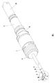
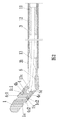
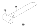
図1は、本発明の一実施例による連続可変角度部を含む側方研削ドリルを示す概略図である。図2は、本発明の一実施例による連続可変角度部を含む側方研削ドリルの前端の部分を示す概略図である。図3は、本発明の一実施例による連続可変角度部を含む側方研削ドリルの後端の部分を示す概略図である。図4は、図1の円Aに含まれる部分の詳細図である。図5は、本発明の一実施例による研削ヘッドを示す概略図である。図6は、本発明の一実施例による柔軟な伝達部を示す概略図である。図に示すように、本発明の連続可変角度部を含む側方研削ドリル、つまり医療研削ドリルは、チューブ本体部品及びチューブ本体部品の前端に配置されている研削ヘッド1を含み、研削ヘッド1は自身の軸の周りで傾斜して回転するように駆動されるように構成されて、チューブ本体部品は外側チューブ本体3及び内側チューブ本体11を含む。内側チューブ本体11は、外側チューブ本体3の内側に同軸に配置されて、外側チューブ本体3及び研削ヘッド11と回転可能に嵌まるように構成される。研削ヘッド1の末端は内側チューブ本体11に円周方向に沿って伝達する形態で関節でつながれて、柔軟な伝達部13は内側チューブ本体11の前端に少なくとも配置されて、柔軟な伝達部13は研削ヘッド1の末端に関節でつながれるように構成されてトルクを伝送することができる。ここに記載する傾斜とは、チューブ本体部品の軸に対して所定の角度で回転することを意味する。ここで記載する自身の軸で回転する研削ヘッドとは、研削ヘッドは研削するように回転駆動されることを意味する。研削ヘッドは、使用するときにチューブ本体部品と同軸になるように調整可能で、作業状況となった後、必要に応じて、研削用の適当な傾斜角度の位置に調節できる。研削ヘッドは、傾斜後、研削を行っても良い。伝達手段は、柔軟な伝達部を介して伝達軸の変化に適応する。
FIG. 1 is a schematic view showing a side grinding drill including a continuously variable angle portion according to an embodiment of the present invention. FIG. 2 is a schematic view showing a front end portion of a side grinding drill including a continuously variable angle portion according to an embodiment of the present invention. FIG. 3 is a schematic view showing a rear end portion of a side grinding drill including a continuously variable angle portion according to an embodiment of the present invention. 4 is a detailed view of a portion included in a circle A in FIG. FIG. 5 is a schematic view showing a grinding head according to an embodiment of the present invention. FIG. 6 is a schematic diagram illustrating a flexible transmission unit according to an embodiment of the present invention. As shown in the drawing, a side grinding drill including a continuously variable angle portion of the present invention, that is, a medical grinding drill, includes a tube body part and a grinding head 1 disposed at a front end of the tube body part. Configured to be driven to tilt and rotate about its own axis, the tube body component includes an
実施例では、研削ヘッド1の末端に開口端がある関節溝1dが形成されて、柔軟な伝達部13の前端には棒状関節部13aが設けられている。棒状関節部13aは、柔軟な伝達部と回転可能に嵌まり、関節溝と関節でつながれて嵌るように構成されている。柔軟な伝達部13が研削ヘッドの傾斜動作の後に研削ヘッドの自身の軸の周りの回転しているところにはまることに加えて、関節溝1d及び棒状関節部13aの間にある少しの移動用空間に傾斜動作後に生じる長さにおける差がはまり、それにより回転が滑らかになり、内側チューブ本体11及び柔軟な伝達部13は外側チューブ本体2から取り外すことができて、組立及び分解に便利となる。
In the embodiment, a joint groove 1 d having an open end is formed at the end of the grinding head 1, and a rod-shaped
実施例では、棒状関節部13a及び柔軟な伝達部13はT字型の構成を形成する。この構成により、関節でつながれた構成の伝達の強さを保証できるだけではなく、傾斜用の関節でつながれた箇所が内側に厚くされた後も外側チューブ本体3を滑らかに通すことができる。勿論、このような構成の関節部は、開口が無い関節溝にも使用可能である。
In the embodiment, the rod-shaped
実施例では、柔軟な伝達部及び棒状関節部の間の接続の根元はT字型の平面においてくびれている。棒状関節部13aが関節溝1dに関節でつながれた後、棒状関節部13aが関節溝1dから横方向に及び回転するように動くときに、このような構成は関節溝の構成に適応できて関節溝1dの溝壁と干渉しないようにできる。
In an embodiment, the base of the connection between the flexible transmission and the bar joint is constricted in a T-shaped plane. After the rod-shaped
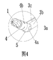
実施例では、研削ヘッドハンドル1aが研削ヘッド1に設けられており、関節溝1dは研削ヘッドハンドル1aの末端に配置されている。外側チューブ本体3の前端には研削ヘッド取付被覆4が一つの自由度の形態で関節でつながれており、研削ヘッドハンドル1aは、研削ヘッド取付被覆4の内側に配置されて、一つの自由度の形態で研削ヘッド取付被覆4と回転可能にはまるように構成されて、研削ヘッド1は研削ヘッド取付被覆4から延長している研削ブレードを有する。一つの自由度で回転可能に嵌まる形態とは、この構成を達成できるあらゆる機械的手段が可能であり、軸方向機械的移動制限を含む。研削ヘッドハンドル1aの構成は、取付及び組み立てに便利で、構成の小型化も保証できて、この分野に適当であり、研削ヘッドは研削ヘッド取付被覆4により駆動できて傾斜動作を実施できる。柔軟な伝達部13は、良好な適合で、ねじ接続又はロッキング接続を介して内側チューブ本体11の前端に接続されて、柔軟な伝達部は必要に応じて取り替えることができて、工具の長期間操作を保証する。棒状関節部13aは柔軟な伝達部13の前端に一体的に形成されている。一つの自由度の形態での関節とは、互いに関節でつながれている部分の間の相対移動が関節の伝達方向に限定されていることを意味して、関節手段は軸部を有する既存の関節でつながれた構成でも良い。このような構成は小さい傾向がある為、一部分に関節溝を設けて、別の部分に関節溝と合う棒状構成又は2つの放射状に対称的なボールの構成に加工することは適切である。図4に示すように、2つの曲線状の関節ジョイント3aは外側チューブ本体3の前端面に半径方向に反対側に形成されて、2つの曲線状の関節溝4aは研削ヘッド取付被覆4の末端面に半径方向に反対側に形成されて、2つの曲線状の関節溝4aは2つの曲線状の関節ジョイント3aを挿入するように構成されて、1つの自由度の関節でつながれた構成を形成している。このように、この構成は簡素で、加工しやすく、関節部が回転するようにたわみ、簡単に分解できる。更に、この構成では、外側チューブ本体の軸と関節部の軸とを同じ平面に配置している。
In the embodiment, the grinding head handle 1a is provided in the grinding head 1, and the joint groove 1d is disposed at the end of the grinding head handle 1a. The front end of the
図に示すように、研削ヘッドハンドル1aは柔軟な伝達部13と関節でつながれた後に軸方向移動用空間を有しており、完全に開口する関節でつながれた構成を形成して、その構成は棒状関節部13aを関節溝1dに直接挿入して形成されて、研削ヘッドハンドル1a及び棒状関節部13aの間の相対的移動を滑らかにする軸方向移動用空間を有して、内側チューブ本体11及び柔軟な伝達部13をいつでも引き出すことができて、掃除及び維持を容易にする。この構成は既存の技術にある自在軸部構成を取り除いて、構成の小型化及び容積の減少を達成して、深く狭い箇所により適している。
As shown in the figure, the grinding head handle 1a has a space for axial movement after it is jointed with the
実施例では、外側チューブ本体は円周方向に沿って回転駆動するように構成されており、そのため研削ヘッド取付被覆及び研削ヘッドは回転駆動するように構成されている。ここに記載する回転とは、研削ヘッド1全体がチューブ本体部品の軸周りで回転して、自在に研削することを達成して、つまり2つの自由度として、傾斜動作及び円周動作を達成できて、それらを組み合わせることができ、異なる方向への複数の作業条件を構成する。研削ヘッドは使用するときにチューブ本体部品と同軸になるように調整できて、作業状況になると、必要に応じて研削に適した傾斜角度となる位置に調整できる。 In the embodiment, the outer tube main body is configured to be rotationally driven along the circumferential direction, and therefore the grinding head mounting cover and the grinding head are configured to be rotationally driven. The rotation described here means that the grinding head 1 as a whole rotates around the axis of the tube body part to achieve free grinding, that is, it can achieve tilting operation and circumferential operation as two degrees of freedom. They can be combined and constitute multiple working conditions in different directions. The grinding head can be adjusted so as to be coaxial with the tube main body part when used, and can be adjusted to a position where an inclination angle suitable for grinding is obtained if necessary.
実施例では、連続可変角度部を含む側方研削ドリルは連結ハンドル9及び駆動部品を更に含む。駆動部品は、検索ヘッド取付被覆4を駆動して傾斜させる傾斜駆動部品及び外側チューブ本体を駆動して円周方向に沿って回転させる方向駆動部品を含む。
In an embodiment, the side grinding drill including the continuously variable angle portion further includes a connecting
傾斜駆動部品は往復中央部及び往復駆動部8を含む。往復中央部の前端は研削ヘッド取付被覆4に接続されて、研削ヘッド取付被覆4が傾斜するように駆動可能であり、研削ヘッド取付被覆4を駆動して傾斜関節方向に回転させて、研削ヘッド1を駆動させて傾斜動作を実施する。往復中央部の後端は、往復駆動部8と少なくとも軸方向に駆動可能に嵌められている。往復駆動部8は、往復駆動部8が連結ハンドル9に対して相対移動可能な形態で、連結ハンドル9と嵌まっており、往復中央部を駆動して往復動作を実施するようにして、研削ヘッド取付被覆4の傾斜動作を達成する。往復駆動部8は、往復駆動部8が連結ハンドル9に対して相対移動可能な形態で、連結ハンドル9と嵌まるか、又はねじ込まれるか、又は他の往復動作の形態で嵌められて、いつでも配置され得る。
The tilt drive component includes a reciprocating central portion and a
方向駆動部品は、研削工具の外側チューブ本体に同軸に固定されている連結スリーブ6と、連結スリーブの外側に配置されている駆動スリーブ7とを含む。駆動スリーブは連結スリーブに対して円周方向に固定されて、連結スリーブに対して軸方向に摺動可能である。外側チューブ本体3は連結スリーブ6に溶接により接続される。連結スリーブ6が駆動スリーブ7に対して相対的に摺動することは、軸方向に平坦なキー(axial flat key)又はスプラインの連係にて達成できるが、ここで説明はされていない。駆動スリーブ7は軸方向に沿って摺動するように構成されて、連結ハンドル9と係合又は解除して、円周方向において制限又は開放されることを達成する。この構成では、連結ハンドル9の前端に端面スプラインを設けることができ、駆動スリーブ7の後端にも端面スプラインを設けることができる。駆動スリーブ7が外力により軸方向に摺動するように駆動されるときに、駆動スリーブ7は手動で駆動できて、連結スリーブ6が回転するように駆動して、外側チューブ本体3を回転するように駆動して、研削ヘッドに回転を実施させる。自在な方向への作用は、回転を研削ヘッド1の自身の軸周りの回転及び傾斜動作と組み合わせることで達成できる。
The directional drive component includes a
実施例では、駆動スリーブ7には後方への仮締め力が備えられて、仮締め力により駆動スリーブ7は連結ハンドル9の前端の近くに配置されて、円周方向において連結ハンドル9と係合する。仮締め力は、バネ又はスナップスプリングにより実現できる。上記の係合は仮締め力により実現され、実行時の間違った動作及び取り外しの問題を回避する。図に示すように、駆動スリーブ7の内側の円にバネ穴が配置されて、柱状バネが連結スリーブ6の外側に配置されて、柱状バネの2つの端は連結スリーブ6の外円に形成されている外側ボス及び駆動スリーブ7の内側の円に形成されている内側ボスのそれぞれに対して押し当てられている。往復中央部の末端は移行スリーブ15と軸方向に固定して接続されている。半径方向駆動アーム15aは、移行スリーブ15の外円に配置されている。半径方向駆動アーム15aは、1つの自由度の形態で往復駆動部8と回転可能に嵌まるように構成されている。図に示すように、半径方向駆動アーム15aは、ねじ山で往復駆動部8と合う押さえスリーブ16を介して軸方向に固定されている。往復駆動部8は雌ねじを有する往復駆動スリーブであり、雌ねじは連結ハンドル9に設けられた雄ねじと合う。くびれ部分は駆動スリーブの後端に配置されている。往復駆動スリーブの前端は駆動スリーブのくびれ部分の外円の外側に配置されている。往復駆動スリーブの後端は連結ハンドルの外側に配置されている。往復駆動スリーブを回転して半径方向駆動アーム15aを駆動して往復動作を実施させることで、既存の技術で起こる一時停止及び移行を回避するように滑らかで正確な動作を達成できる。同時に、ねじ山係合により、部品は小型で完全性を有するようになる。駆動スリーブ7の後端にはくびれ部分が設けられている。往復駆動スリーブの前端は、駆動スリーブ7のくびれ部分の外円の外側に配置されている。往復駆動スリーブの前端の内側の円には段が形成されている。段は押さえカバーに接続して、円形の溝を形成する。図に示すように、半径方向駆動アーム15aは円形の溝内に挿入されて嵌合構成となり、この構成は軸方向に固定されて円周方向に摺動可能である。もちろん、複数の半径方向駆動アーム15aが円周方向に沿って配置されても良い。図に示すように、対称的に配置されている2つの半径方向駆動アームは駆動力を均等に伝達できる。半径方向駆動アームは、駆動スリーブ及び連結ハンドル9の間に配置されて、駆動スリーブ及び往復駆動スリーブの間に配置されているため、動作を干渉しないように、半径方向駆動アームは駆動スリーブ7及び連結ハンドル9の間の端面スプラインには近づけないべきである。図に示すように、往復駆動スリーブの後端は連結ハンドル9の外側に配置されている。連結ハンドルの外側に配置されている往復駆動スリーブの後端は、ねじにより連結ハンドルと嵌まり、動作をしやすくしている。
In the embodiment, the
連続可変角度部を含む側方研削ドリルの末端には、電源に接続しているコネクタ10が設けられている。連結ハンドル9の内側面には、コネクタ10を支持するために図3に示す支持移行スリーブ17が支持体として設けられている。支持移行スリーブ17の前端は移行スリーブ15の外側に配置されて移行スリーブ15と回転可能に嵌まり、支持移行スリーブ17の後端は密閉移行スリーブ18の内側に回転可能に嵌まるように配置される。密閉移行スリーブ18は回転可能に嵌まり、必要な密閉リング及び滑り軸受が設けられているが、ここでは記載していない。
A
本発明は、連続可変角度部を含む側方研削ドリルの特別な実施例も記載しており、連続可変角度部を含む側方研削ドリルであって、チューブ本体部品と、前記チューブ本体部品の前端に配置されている研削ヘッド1であって、自身の軸周りに傾斜及び回転するように駆動されるように構成されている前記研削ヘッドと、を備え、前記チューブ本体部品は外側チューブ本体3と前記外側チューブ本体3の内側に同軸に配置されている内側チューブ本体11とを含み、前記内側チューブ本体11は前記外側チューブ本体3と前記研削ヘッド1と回転可能に嵌合するように構成されて、前記外側チューブ本体の前記前端は1つの自由度で研削ヘッド取付被覆4と関節でつながれて、研削ヘッドハンドル1aが前記研削ヘッド1に設けられて、1つの自由度で前記研削ヘッドハンドル1aと回転可能に嵌合するように構成される位置制限リング1cが前記研削ヘッドハンドル1aに設けられて、前記研削ヘッドハンドル1aは軸方向位置制限の形態で前記位置制限リング1cを介して前記研削ヘッド取付被覆4の内側に配置されることを特徴とする。上記のように、構成は簡単で、分解及び組立も容易である。研削ヘッドハンドル1aは研削ヘッド取付被覆4内に直接挿入することができて、軸方向の位置を制限することを実現する。円形の溝に挿入する形態は、1つの自由度で回転可能に嵌まる形態で殆ど使用できる。
The invention also describes a special embodiment of a side grinding drill including a continuously variable angle part, a side grinding drill including a continuously variable angle part, comprising a tube body part and a front end of said tube body part The grinding head 1 arranged to be driven to tilt and rotate about its own axis, the tube body part being an
実施例では、研削ヘッド取付被覆4は、外側スリーブ及び外側スリーブ内に配置されている内側スリーブ4cを含む。移動制限リング1cには2つの放射対称な移動制限突起部1c1、1c2が設けられている。研削ヘッドハンドル1aの外円には、環状移動制限溝1bが設けられて、環状移動制限溝1bは移動制限リング1cを所定の位置に置いて基本的な移動用空間を含むように構成されて、移動制限リング1cを環状移動制限溝1b内に挿入することにより1つの自由度で回転可能な嵌合が達成される。内側スリーブ4cには、2つの放射対称な軸方向開口溝4c1、4c2が設けられている。外側スリーブには、外側スリーブを軸方向に通っている移動制限貫通孔4bが設けられている。外側スリーブは、軸方向に開口がある開口スリーブである。研削ヘッドハンドル1aは、内側スリーブ4cの内側に配置されて、移動制限リング1cの2つの移動制限突起部1c1、1c2が軸方向に開口している溝に沿って嵌まっていて、一方の移動制限突起部1c1は移動制限貫通孔内に挿入されて、もう一方の移動制限突起部1c2は外側スリーブの内側壁に当接する。研削ヘッド取付被覆4の外側スリーブは軸方向の開口を有し、移動制限リング1cを固定するために放射状に弾性である。図2に示すように、外側スリーブの軸方向開口は、移動制限貫通孔に対して45度の角度で外側スリーブに配置されている。取り付けるときに、研削ヘッドハンドル1a及び移動制限リング1cは内側スリーブ4c内に一緒に配置されて、2つの移動制限突起部1c1、1c2は放射状に制限されて圧縮され、移動制限リング1cが取付位置に摺動すると、一方の移動制限突起部1c1は移動制限突起部1c1の移動制限貫通孔内に挿入されて、軸方向への移動制限が実現される。取り外すとき、移動制限貫通孔内の移動制限突起部1c1は放射状に押されて、移動制限リング1c(位置制限リングとは開口しているリングで、環状位置制限溝1b内に取り付けて変形するのに便利なものである)自身及び外側スリーブは変形できて、移動制限突起部1c1は移動制限貫通孔4bの内径から半径方向に内側に取りはずすことができ、研削ヘッドハンドルを取り外すことができる。図に示すように、外側スリーブは軸方向開口が設けられているだけではなく、円周方向において円周溝も設けられている。円周溝は軸方向開口溝の縁に開口があり、組み立て及び分解における難しさを減少させる。
In an embodiment, the grinding
本実施例による連続可変角度部を含む側方研削ドリルは上記の課題を解決する手段と組み合わせて使用して、より高い効果を得ることができる。 The side grinding drill including the continuously variable angle portion according to the present embodiment can be used in combination with the means for solving the above-described problems, thereby obtaining a higher effect.
本発明は更に連続可変角度部を含む前記側方研削ドリルを記載して、連続可変角度部を含む前記側方研削ドリルはチューブ本体部品と、前記チューブ本体部品の前端に配置されている研削ヘッド1であって、自身の軸周りで傾斜及び回転するように駆動されるように構成されている前記研削ヘッドと、を備え、前記チューブ本体部品は外側チューブ本体3と前記外側チューブ本体の内側に同軸に配置される内側チューブ本体11とを含み、前記内側チューブ本体11は前記外側チューブ本体3と前記研削ヘッド1と回転可能に嵌合するように構成されて、前記外側チューブ本体3の前記前端は1つの自由度で研削ヘッド取付被覆4と関節でつながれて、前記研削ヘッド1は前記研削ヘッド取付被覆4に取り付けられて前記研削ヘッド取付被覆4と前記円周方向に沿って回転可能に嵌合するように構成されて、前記研削ヘッド1は前記研削ヘッド取付被覆4から延出している研削ブレードを有し、関節の回転方向に傾斜するように前記研削ヘッド取付被覆を駆動するように構成される往復中間部が前記研削ヘッド取付被覆4に設けられて、前記往復中間部は前記研削ヘッド取付被覆の傾斜動作の方向への移動用空間を少なくとも有することを特徴として、移動用空間は研削ヘッド取付被覆4が直接関節でつながれた後に前記研削ヘッド取付被覆4の傾斜動作により起こる往復駆動部の放射状動作を収容する。上記により、構成は簡単で有用である。
The present invention further describes the side grinding drill including a continuously variable angle portion, wherein the side grinding drill including the continuously variable angle portion is a tube body part and a grinding head disposed at a front end of the tube body part. 1 and the grinding head configured to be driven to tilt and rotate about its own axis, the tube body part being located inside the
実施例では、往復中央部は内側チューブ本体11及び外側チューブ本体3の間に配置されている中間チューブ本体12であり、中間チューブ本体12と内側チューブ本体11との間及び中間チューブ本体12と外側チューブ本体3との間に基本的な移動用空間がある。この基本的な移動用空間は、研削ヘッド取付被覆4が傾斜しているときに中間チューブ本体により起こる放射状の変位を収容する。中間チューブ本体12の前端は前側へ延長して傾斜関節部5を形成して、傾斜関節部5は研削ヘッド取付被覆と関節でつながれるように使用されて、傾斜関節部5は剛性である。このように、中間チューブ本体12は基本的な移動用空間を用いて研削ヘッド取付被覆が傾斜しているときの小さな基本的な変位を収容することができて、傾斜関節の剛性な構成は研削ヘッド取付被覆を傾斜するように滑らかに駆動できる。構成は簡単及びコンパクトで、複雑な構成による容量の増量を回避でき、手術の成功を保証する。図に示すように、傾斜関節部5は剛性であり、厚みのある構成である。
In the embodiment, the reciprocating central portion is an
傾斜関節部5は中間チューブ本体に固定して接続されているパップジョイント(pup joint)に形成されて、傾斜関節部5は直接中間チューブ本体に形成することもできて、これにより本発明の目的は影響されない。本実施例は上記の技術的な課題解決手段と組み合わすことができるため、中間チューブ本体12のレール端は上記移行スリーブ15に軸方向に固定して接続されて、移行スリーブ15の外円には半径方向駆動アーム15aが設けられている。実施例では、移行スリーブ15は中間チューブ本体12に溶接により接続されて、移行スリーブ15及び半径方向駆動アーム15aは一体的に形成されている。半径方向駆動アーム15aは1つの自由度の形態で往復駆動部と回転可能に嵌合して、前方及び後方駆動を達成できる。これにより、構成は簡単でコンパクトで、組み立て及び分解に便利である。
The inclined joint 5 can be formed in a pup joint that is fixedly connected to the intermediate tube body, and the inclined joint 5 can also be formed directly in the intermediate tube body. Is not affected. Since this embodiment can be combined with the above technical problem solving means, the rail end of the
本発明は連続可変角度部を含む側方研削ドリルの特別な実施例も記載して、側方研削ドリルはチューブ本体部品及びチューブ本体部品の前端に配置された研削ヘッド1を含み、研削ヘッドは自身の軸の周りで傾斜及び回転して駆動するように構成されて、チューブ本体部品は外側チューブ本体3及び外側チューブ本体3の内側に同軸に配置される内側チューブ本体11を含む。内側チューブ本体11は、外側チューブ本体3及び研削ヘッド1と回転可能に嵌るように構成される。外側チューブ本体3の前端には研削ヘッド取付被覆4が設けられている。研削ヘッド取付被覆4は、研削ヘッド1が取り付けられるように構成されて、研削ヘッド1が傾斜して駆動するように構成される。研削ヘッド取付被覆4の後端及び外側チューブ本体の前端は1つの自由度の関節でつながれた構成を、関節ジョイント及び関節溝が相互に接続している形態で、形成して、研削ヘッド取付被覆4と関節でつながれる外側チューブ本体3の一部が厚くなる。この様な設計では関節でつながれた構成が十分な厚さを有して強度が増加して、関節でつながれた構成の中間には狭い通路ができている。厚くした構成は、曲がる部分が研削のときにより大きな横に曲がるモーメントに耐えることを促進して、手術の成功を保証する。
The invention also describes a special embodiment of a side grinding drill including a continuously variable angle part, the side grinding drill comprising a tube body part and a grinding head 1 arranged at the front end of the tube body part, Constructed to drive tilted and rotated about its own axis, the tube body component includes an
実施例では、研削ヘッド取付被覆4と関節でつながれる外側チューブ本体3の部分には、外側チューブ本体3の前端が固定されて接続されるように外側チューブ関節部3bが設けられている。外側チューブ本体3は外側チューブ関節部3bとねじ山又は溶接により接続できるが、上記についてはここには記載はない。2つの曲線状の関節ジョイント3aは外側チューブ関節部3bの前端面3cに放射状に反対側に形成されている。2つの曲線状の関節溝4aは、研削ヘッド取付被覆4の末端面に放射状に反対側に形成されて、2つの曲線状の関節ジョイント3aが挿入されるように構成されて、1つの自由度の関節でつながれた構成を形成する。外側チューブ関節部3bは2つの曲線状の関節ジョイント3aの間に配置されて、内側チューブ本体11が通るチャネルを形成する。外側チューブ関節部3bは、チャネルの半径方向内側へ厚くなっている。内側チューブ本体11(柔軟な伝達部13を含む)の頭部の特別な形は、曲線状の複数の関節ジョイントの間の狭いチャネル(厚くなることで起こる)を通れるように設計されて、2つの曲線状の関節ジョイント及び前の研削ヘッドから遠ざけられて回転駆動するように自在継手を形成している。この構成では、関節ジョイントは厚くなっていて、外側チューブ関節部3b及び外側チューブ本体3の接続構成が使用されているため、強度を増加させるだけでなく、組み立ても促進される。
In the embodiment, an outer tube
本発明は、研削の配向を変化させるように連続可変角度部を含む側方研削ドリルを駆動する駆動部品も記載して、連続可変角度部を含む側方研削ドリルは連結ハンドル9及び傾斜するように連続可変角度部を含む側方研削ドリルの研削ヘッド1を駆動する傾斜駆動部品を含む。傾斜駆動部品は往復中央部及び往復駆動部8を含む。往復中央部の前端は研削ヘッド1に接続されて、研削ヘッド1が傾斜するように駆動可能である形態であり、往復中央部の後端は少なくとも軸方向に往復駆動部8と駆動可能に嵌合している。往復駆動部8は連結ハンドル9と嵌合しており、往復駆動部は連結ハンドルに対して相対的に移動可能な形態となっている。
The present invention also describes a drive component that drives a side grinding drill that includes a continuously variable angle portion to change the grinding orientation so that the side grinding drill that includes a continuously variable angle portion tilts with the connecting
駆動部品は方向駆動部品を更に含む。方向駆動部品は、連続可変角度部を含む側方研削ドリルの外側チューブ本体3に同軸に固定されている連結スリーブ6と、連結スリーブ6の外側に配置されている駆動スリーブ7とを含む。駆動スリーブ7は円周方向に連結スリーブ6に固定されて、軸方向に連結スリーブ6に対して摺動可能である。そして、駆動スリーブ7は軸方向に沿って摺動するように構成されて、接続ハンドル9と係合又は脱着して円周方向における制限及び解除を実現する。
The drive component further includes a directional drive component. The direction drive component includes a
駆動スリーブ7には後方への仮締め力が備えられて、それにより駆動スリーブ7が接続ハンドル9の前端に近接して円周方向において接続ハンドル9と係合するようになる。中間チューブの末端は移行スリーブ15と軸方向に固定されて接続される。半径方向駆動アーム15aは移行スリーブ15の外円に配置されて、半径方向駆動アーム15aは1つの自由度で往復駆動部8と回転可能に嵌合するように構成される。往復駆動部8は雌ねじを有する往復駆動スリーブであり、雌ねじは接続ハンドル9に設けられる雄ねじと合う。くびれ部分は駆動スリーブ7の後端に配置されて、往復駆動スリーブの前端は駆動スリーブ7のくびれ部分の外円の外側に配置されて、往復駆動スリーブの後端は接続ハンドル9の外側に配置される。
The
上記の本発明の好ましい実施例はそれぞれ1つの技術的な解決となり得る。当業者は、上記の全ての好ましい実施例を組み合わせて、本発明の目的を達成することができると理解すべきである。つまり前述の構成は独立して技術的な解決となるか、又は、ここには記載されていないが、組み合わせて本発明の側方研削ドリルに適用できる。 Each of the preferred embodiments of the present invention described above can be a technical solution. It should be understood by those skilled in the art that all the preferred embodiments described above can be combined to achieve the objectives of the present invention. In other words, the above-described configuration is an independent technical solution, or although not described here, can be combined and applied to the side grinding drill of the present invention.
上記は本発明の詳細な好ましい実施例であり、本発明の範囲を制限するとみなされるべきではない。なお、本発明の当業者には、本発明の範囲及び範疇から逸脱することなく、変形例及び改良例は明らかとなるだろう。従って、本発明の範囲は添付の請求の範囲により規定される。
The above are detailed preferred embodiments of the present invention and should not be construed as limiting the scope of the invention. It will be apparent to those skilled in the art that modifications and improvements can be made without departing from the scope and scope of the invention. Accordingly, the scope of the invention is defined by the appended claims.
Claims (9)
チューブ本体部品と、
前記チューブ本体部品の前端に配置されている研削ヘッドであって、自身の軸周りに傾斜及び回転するように駆動されるように構成されている前記研削ヘッドと、
を備え、
前記チューブ本体部品は外側チューブ本体と前記外側チューブ本体の内側に同軸に配置されている内側チューブ本体とを含み、前記内側チューブ本体は前記外側チューブ本体と前記研削ヘッドと回転可能に嵌合するように構成されて、
少なくとも前記内側チューブ本体の前端に配置されている柔軟な伝達部が、前記研削ヘッドの末端に関節でつながれるように、かつ、トルクを伝達可能に構成され、当該構成により、前記研削ヘッドの前記末端は、伝達する形態で前記内側チューブ本体に円周方向に沿って関節でつながれ、
開口端を含む関節溝が前記研削ヘッドの前記末端に形成されて、
棒状関節部が前記柔軟な伝達部の前端に設けられて、前記棒状関節部は前記柔軟な伝達部と回転可能に嵌合して前記関節溝と関節でつながれて嵌合するように構成されることを特徴とする。 A side grinding drill including a continuously variable angle part,
Tube body parts,
A grinding head disposed at a front end of the tube body component, the grinding head configured to be driven to tilt and rotate about its own axis;
With
The tube body component includes an outer tube body and an inner tube body coaxially disposed inside the outer tube body, and the inner tube body is rotatably fitted to the outer tube body and the grinding head. Composed of
A flexible transmission portion disposed at least at the front end of the inner tube main body is configured to be jointed to the distal end of the grinding head and capable of transmitting torque. The end is articulated along the circumferential direction to the inner tube body in a transmitting manner,
A joint groove including an open end is formed at the end of the grinding head;
A rod-shaped joint portion is provided at a front end of the flexible transmission portion, and the rod-shaped joint portion is configured to be rotatably fitted to the flexible transmission portion and to be coupled by fitting with the joint groove. It is characterized by that.
前記棒状関節部及び前記柔軟な伝達部はT字型の構成を形成することを特徴とする。 The side grinding drill including the continuously variable angle portion according to claim 1,
The rod-shaped joint part and the flexible transmission part form a T-shaped configuration.
前記柔軟な伝達部及び前記棒状関節部の間の接続の根元はT字型の平面でくびれていることを特徴とする。 The side grinding drill including the continuously variable angle portion according to claim 2,
The base of the connection between the flexible transmission part and the rod-shaped joint part is narrowed by a T-shaped plane.
研削ヘッドハンドルが前記研削ヘッドに設けられて、前記関節溝は前記研削ヘッドハンドルの前記末端に配置されて、前記外側チューブ本体の前記前端は1つの自由度で研削ヘッド取付被覆に関節でつながれて、前記研削ヘッドハンドルは前記研削ヘッド取付被覆の内側に配置されて、1つの自由度で前記研削ヘッド取付被覆と回転可能に嵌合するように構成されて、前記研削ヘッドは前記研削ヘッド取付被覆から延出している研削ブレードを有し、前記柔軟な伝達部は前記内側チューブ本体の前記前端に連結されて、前記棒状関節部は前記柔軟な伝達部の前記前端に一体的に形成されることを特徴とする。 The side grinding drill including the continuously variable angle portion according to claim 1 or 2,
A grinding head handle is provided on the grinding head, the joint groove is disposed at the distal end of the grinding head handle, and the front end of the outer tube body is articulated to the grinding head mounting sheath in one degree of freedom. The grinding head handle is disposed inside the grinding head mounting sheath and is configured to rotatably fit with the grinding head mounting sheath in one degree of freedom; The flexible transmission part is connected to the front end of the inner tube body, and the bar joint is formed integrally with the front end of the flexible transmission part. It is characterized by.
前記外側チューブ本体は前記円周方向に沿って回転駆動されるように構成されて、それにより前記研削ヘッド取付被覆と前記研削ヘッドとが回転駆動されるように構成されることを特徴とする。 The side grinding drill including the continuously variable angle portion according to claim 4,
The outer tube main body is configured to be rotationally driven along the circumferential direction, whereby the grinding head mounting cover and the grinding head are configured to be rotationally driven.
前記連続可変角度部を含む前記側方研削ドリルは連結ハンドルと駆動部品とを更に含み、
前記駆動部品は、前記研削ヘッド取付被覆が傾斜するように駆動させる傾斜駆動部品及び前記外側チューブ本体を前記円周方向に沿って回転するように駆動させる方向駆動部品を含み、
前記傾斜駆動部品は往復中間部と往復駆動部とを含み、
前記研削ヘッド取付被覆が傾斜するように駆動可能な形態で、前記往復中間部の前記前端は前記研削ヘッド取付被覆に接続されて、
前記往復中間部の後端は、前記往復駆動部と少なくとも軸方向に駆動可能に嵌合されて、
前記往復駆動部は、前記往復駆動部が前記連結ハンドルに対して移動可能な形態で、前記連結ハンドルと嵌合して、
前記方向駆動部品は、前記外側チューブ本体に同軸に固定されている連結スリーブと、前記連結スリーブの外側に配置される駆動スリーブと、を含み、
前記駆動スリーブは、前記連結スリーブと前記円周方向において固定されて、前記連結スリーブに対して前記軸方向に摺動可能であり、
前記駆動スリーブは、前記軸方向に沿って摺動するように構成されて、前記連結ハンドルと係合又は脱着して前記円周方向において制限又は解除を実現することを特徴とする。 The side grinding drill including the continuously variable angle portion according to claim 5,
The side grinding drill including the continuously variable angle portion further includes a connection handle and a driving component,
The drive component includes a tilt drive component that drives the grinding head mounting sheath to tilt, and a direction drive component that drives the outer tube body to rotate along the circumferential direction,
The tilt drive component includes a reciprocating intermediate portion and a reciprocating drive portion,
In a form that can be driven so that the grinding head mounting cover is inclined, the front end of the reciprocating intermediate portion is connected to the grinding head mounting cover,
The rear end of the reciprocating intermediate part is fitted with the reciprocating drive part so as to be driven at least in the axial direction,
The reciprocating drive unit is fitted with the connection handle in a form in which the reciprocation drive unit is movable with respect to the connection handle,
The directional drive component includes a connection sleeve fixed coaxially to the outer tube body, and a drive sleeve disposed outside the connection sleeve,
The drive sleeve is fixed in the circumferential direction with the connection sleeve, and is slidable in the axial direction with respect to the connection sleeve;
The drive sleeve is configured to slide along the axial direction, and is configured to engage or disengage from the connection handle to achieve restriction or release in the circumferential direction.
前記駆動スリーブには後方への仮締め力が備えられて、前記後方への仮締め力により前記駆動スリーブを前記連結ハンドルの前記前端の近くに配置させて前記連結ハンドルと前記円周方向において係合させて、
前記往復中間部の前記末端は移行スリーブと軸方向に固定して接続されて、半径方向駆動アームが前記移行スリーブの外円に配置されて、前記半径方向駆動アームは1つの自由度で前記往復駆動部と回転可能に嵌合するように構成されて、
前記往復駆動部は、雌ねじを含む往復駆動スリーブであり、前記雌ねじは前記連結ハンドルに設けられている雄ねじと合い、
くびれ部分が前記駆動スリーブの後端に設けられて、前記往復駆動スリーブの前記前端は前記駆動スリーブの前記くびれ部分の外円の外側に配置されて、前記往復駆動スリーブの前記後端は前記連結ハンドルの外側に配置されていることを特徴とする。 The side grinding drill including the continuously variable angle portion according to claim 6,
The drive sleeve is provided with a rearward fastening force, and the drive sleeve is arranged near the front end of the connection handle by the rearward fastening force to engage the connection handle in the circumferential direction. Combined
The end of the reciprocating intermediate portion is fixedly connected to the transition sleeve in an axial direction, a radial drive arm is disposed on the outer circle of the transition sleeve, and the radial drive arm is reciprocated in one degree of freedom. It is configured to fit rotatably with the drive,
The reciprocating drive unit is a reciprocating drive sleeve including a female screw, and the female screw is fitted with a male screw provided on the connection handle,
A constricted portion is provided at the rear end of the drive sleeve, the front end of the reciprocating drive sleeve is disposed outside an outer circle of the constricted portion of the drive sleeve, and the rear end of the reciprocating drive sleeve is the connection It is arranged outside the handle.
チューブ本体部品と、
前記チューブ本体部品の前端に配置されている研削ヘッドであって、自身の軸周りで傾斜及び回転するように駆動されるように構成されている前記研削ヘッドと、
を備え、
前記チューブ本体部品は外側チューブ本体と前記外側チューブ本体の内側に同軸に配置されている内側チューブ本体とを含み、前記内側チューブ本体は前記外側チューブ本体と前記研削ヘッドと回転可能に嵌合するように構成されて、
前記外側チューブ本体の前記前端には前記研削ヘッドを取り付けて研削ヘッドが傾斜するように駆動するように構成される研削ヘッド取付被覆が設けられ、前記研削ヘッド取付被覆の後端と前記外側チューブ本体の前記前端は1つの自由度で関節でつながれており、該後端と該前端が関節でつながれた構成は、前記外側チューブ本体に形成された関節ジョイント及び前記研削ヘッド取付被覆に形成された関節溝が相互に接続する形態で、形成されており、前記研削ヘッド取付被覆と関節でつながれる前記外側チューブ本体の部分は厚くされており、
少なくとも前記内側チューブ本体の前端に配置されている柔軟な伝達部が、前記研削ヘッドの末端に関節でつながれるように、かつ、トルクを伝達可能に構成され、当該構成により、前記研削ヘッドの前記末端は、伝達する形態で前記内側チューブ本体に円周方向に沿って関節でつながれ、
開口端を含む関節溝が前記研削ヘッドの前記末端に形成されて、
棒状関節部が前記柔軟な伝達部の前端に設けられて、前記棒状関節部は前記柔軟な伝達部と回転可能に嵌合して前記関節溝と関節でつながれて嵌合するように構成されることを特徴とする。 A side grinding drill including a continuously variable angle part,
Tube body parts,
A grinding head disposed at a front end of the tube body component, the grinding head configured to be driven to tilt and rotate about its own axis;
With
The tube body component includes an outer tube body and an inner tube body coaxially disposed inside the outer tube body, and the inner tube body is rotatably fitted to the outer tube body and the grinding head. Composed of
Said outer to said front end of the tube body the grinding head mounted configured grinding head is driven so as to be inclined grinding head mounted coating provided et al is, the outer tube and the end after the grinding head mounted cover The front end of the main body is articulated with one degree of freedom, and the configuration in which the rear end and the front end are articulated is formed in the joint joint formed on the outer tube main body and the grinding head mounting cover. The joint groove is formed in a form to be connected to each other, and the portion of the outer tube body that is jointed with the grinding head mounting cover is thickened,
A flexible transmission portion disposed at least at the front end of the inner tube main body is configured to be jointed to the distal end of the grinding head and capable of transmitting torque. The end is articulated along the circumferential direction to the inner tube body in a transmitting manner,
A joint groove including an open end is formed at the end of the grinding head;
A rod-shaped joint portion is provided at a front end of the flexible transmission portion, and the rod-shaped joint portion is configured to be rotatably fitted to the flexible transmission portion and to be coupled by fitting with the joint groove. It is characterized by that.
前記研削ヘッド取付被覆と関節でつながれる前記外側チューブ本体の前記部分には、前記外側チューブ本体の前記前端に固定して接続する外側チューブ関節部が設けられて、2つの曲線状の関節ジョイントは前記外側チューブ関節部の前端面に放射状に反対側に形成されて、2つの曲線状の関節溝は、前記研削ヘッド取付被覆の末端面に放射状に反対側に形成されて、2つの曲線状の前記関節ジョイントを挿入して1つの自由度の関節でつながれた構成を形成するように構成されて、
前記外側チューブ関節部は2つの曲線状の前記関節ジョイントの間に配置されて前記内側チューブ本体が通るチャネルを形成して、前記外側チューブ関節部はチャネル内で放射状に内側に厚くなることを特徴とする。
The side grinding drill including the continuously variable angle portion according to claim 8,
The portion of the outer tube body that is articulated with the grinding head mounting sheath is provided with an outer tube joint that is fixedly connected to the front end of the outer tube body, and the two curved joint joints are is formed on the opposite side to the radially before the end surface of the outer tube joint, the two curved joint groove, said formed opposite radially on the end face end of the grinding head mounted cover, the two curved Configured to insert the joint joint to form a jointed joint with one degree of freedom;
The outer tube joint is disposed between two curved joints to form a channel through which the inner tube body passes, and the outer tube joint is thickened radially inward in the channel. And
Applications Claiming Priority (7)
| Application Number | Priority Date | Filing Date | Title |
|---|---|---|---|
| CN201310632414 | 2013-11-29 | ||
| CN201310632414.1 | 2013-11-29 | ||
| CN201310641876.X | 2013-12-03 | ||
| CN201310641876.XA CN104605913B (en) | 2013-11-29 | 2013-12-03 | Medical grinding knife tool |
| CN201410041760.7 | 2014-01-28 | ||
| CN201410041760.7A CN103767759B (en) | 2014-01-28 | 2014-01-28 | Medical grinding cutter |
| PCT/CN2014/087552 WO2015078229A1 (en) | 2013-11-29 | 2014-09-26 | Electrodeless variable angle sideways drill grinding head and drive components thereof |
Related Child Applications (2)
| Application Number | Title | Priority Date | Filing Date |
|---|---|---|---|
| JP2017110056A Division JP6303048B2 (en) | 2013-11-29 | 2017-06-02 | Side grinding drill with continuously variable angle |
| JP2017110065A Division JP6410876B2 (en) | 2013-11-29 | 2017-06-02 | Side grinding drill including continuously variable angle part and its driving parts |
Publications (2)
| Publication Number | Publication Date |
|---|---|
| JP2016537167A JP2016537167A (en) | 2016-12-01 |
| JP6227159B2 true JP6227159B2 (en) | 2017-11-08 |
Family
ID=53198402
Family Applications (3)
| Application Number | Title | Priority Date | Filing Date |
|---|---|---|---|
| JP2016553696A Active JP6227159B2 (en) | 2013-11-29 | 2014-09-26 | Side grinding drill with continuously variable angle |
| JP2017110056A Active JP6303048B2 (en) | 2013-11-29 | 2017-06-02 | Side grinding drill with continuously variable angle |
| JP2017110065A Active JP6410876B2 (en) | 2013-11-29 | 2017-06-02 | Side grinding drill including continuously variable angle part and its driving parts |
Family Applications After (2)
| Application Number | Title | Priority Date | Filing Date |
|---|---|---|---|
| JP2017110056A Active JP6303048B2 (en) | 2013-11-29 | 2017-06-02 | Side grinding drill with continuously variable angle |
| JP2017110065A Active JP6410876B2 (en) | 2013-11-29 | 2017-06-02 | Side grinding drill including continuously variable angle part and its driving parts |
Country Status (6)
| Country | Link |
|---|---|
| US (1) | US10178998B2 (en) |
| EP (3) | EP3000417B1 (en) |
| JP (3) | JP6227159B2 (en) |
| KR (3) | KR101740976B1 (en) |
| ES (1) | ES2775187T3 (en) |
| WO (1) | WO2015078229A1 (en) |
Families Citing this family (23)
| Publication number | Priority date | Publication date | Assignee | Title |
|---|---|---|---|---|
| WO2016008880A1 (en) | 2014-07-14 | 2016-01-21 | KB Medical SA | Anti-skid surgical instrument for use in preparing holes in bone tissue |
| US10765438B2 (en) | 2014-07-14 | 2020-09-08 | KB Medical SA | Anti-skid surgical instrument for use in preparing holes in bone tissue |
| KR102547935B1 (en) * | 2016-06-24 | 2023-06-27 | 삼성디스플레이 주식회사 | Grinding device for substrate |
| US11207081B2 (en) | 2016-10-21 | 2021-12-28 | University Of Louisville Research Foundation, Inc. | Systems and methods for intramedullary preparations |
| WO2018180242A1 (en) | 2017-03-31 | 2018-10-04 | Nttテクノクロス株式会社 | Behavior specifying device, behavior specifying method and program |
| JP7250758B2 (en) | 2017-08-10 | 2023-04-03 | プロ-デツクス・インコーポレイテツド | Articulation tool for endoscopic placement of fasteners |
| DE102017010033A1 (en) * | 2017-10-27 | 2019-05-02 | Joimax Gmbh | Medical device |
| CN108261225A (en) * | 2018-03-12 | 2018-07-10 | 武汉多可特医疗器械有限公司 | A kind of medical curved grinder heads with LED light |
| KR102089782B1 (en) * | 2018-05-02 | 2020-03-16 | 고려대학교 산학협력단 | Surgical awl |
| DE202019105420U1 (en) * | 2019-10-01 | 2019-11-13 | Richard Wolf Gmbh | Endoscopic instrument |
| CN111658062B (en) * | 2020-06-30 | 2021-06-04 | 重庆西山科技股份有限公司 | Elbow pipe grinding tool with angle-adjustable tool bit |
| CN113069199B (en) * | 2021-03-29 | 2022-04-29 | 温州医科大学附属第二医院(温州医科大学附属育英儿童医院) | Clamping device for kirschner wire |
| CN113456164B (en) * | 2021-06-30 | 2023-04-25 | 重庆西山科技股份有限公司 | Direction-changing grinding tool with bending part and compound surgical instrument |
| DE102021119386A1 (en) | 2021-07-27 | 2023-02-02 | Aesculap Ag | Bendable shaft for a medical hand instrument |
| CN113558718B (en) * | 2021-07-31 | 2023-11-03 | 任晓东 | External shock wave therapeutic device |
| CN113855115B (en) * | 2021-10-29 | 2023-06-09 | 温州医科大学附属第一医院 | Connecting rod type endoscopic instrument with changeable angle |
| CN114129200B (en) * | 2021-12-07 | 2024-03-26 | 山东威瑞外科医用制品有限公司 | Clamp head handle |
| DE102022107972A1 (en) | 2022-04-04 | 2023-10-05 | Aesculap Ag | Medical tool system |
| DE102022107970A1 (en) | 2022-04-04 | 2023-10-05 | Aesculap Ag | Flexible surgical tool with integrated bearing assembly |
| CN114831680A (en) * | 2022-06-02 | 2022-08-02 | 北京天星博迈迪医疗器械有限公司 | Full suture anchor implantation device |
| DE102022119983A1 (en) | 2022-08-09 | 2024-02-15 | Aesculap Ag | Medical motor handpiece with angle adjusting ring and medical hand instrument |
| DE102022119982A1 (en) | 2022-08-09 | 2024-02-15 | Aesculap Ag | Motor handpiece with rotatable control element and medical hand instrument |
| DE102022119979A1 (en) | 2022-08-09 | 2024-02-15 | Aesculap Ag | Medical motor handpiece for 2-in-1 operation and medical hand instrument with 2-in-1 operation |
Family Cites Families (23)
| Publication number | Priority date | Publication date | Assignee | Title |
|---|---|---|---|---|
| JPH01119241A (en) | 1987-10-30 | 1989-05-11 | Olympus Optical Co Ltd | Surgical incision instrument |
| US5752973A (en) | 1994-10-18 | 1998-05-19 | Archimedes Surgical, Inc. | Endoscopic surgical gripping instrument with universal joint jaw coupler |
| WO1999021686A1 (en) | 1997-10-28 | 1999-05-06 | Romolo Bertani | Device for supporting a mandrel with angular transmission |
| US6740090B1 (en) | 2000-02-16 | 2004-05-25 | Trans1 Inc. | Methods and apparatus for forming shaped axial bores through spinal vertebrae |
| US6783533B2 (en) | 2001-11-21 | 2004-08-31 | Sythes Ag Chur | Attachable/detachable reaming head for surgical reamer |
| US8221424B2 (en) * | 2004-12-20 | 2012-07-17 | Spinascope, Inc. | Surgical instrument for orthopedic surgery |
| WO2005062827A2 (en) * | 2003-12-19 | 2005-07-14 | Spinascope Inc. | Dissecting high speed burr for spinal surgery |
| US7210881B2 (en) | 2003-12-30 | 2007-05-01 | Greenberg Alex M | Sleeved stop for a drill bit |
| US7503921B2 (en) * | 2004-01-13 | 2009-03-17 | Symmetry Medical, Inc. | Variable angle orthopaedic reamer driver |
| US8784421B2 (en) | 2004-03-03 | 2014-07-22 | Boston Scientific Scimed, Inc. | Apparatus and methods for removing vertebral bone and disc tissue |
| DE502007003014D1 (en) * | 2007-07-20 | 2010-04-15 | Wolf Gmbh Richard | Endoscopic instrument |
| CN201346224Y (en) | 2009-01-19 | 2009-11-18 | 梁雄 | Reciprocating type bone saw |
| CN201394046Y (en) | 2009-04-29 | 2010-02-03 | 李庆波 | Eccentric amplifier |
| DE102009042491A1 (en) | 2009-05-29 | 2010-12-02 | Aesculap Ag | Surgical instrument for use as shaver, has zone arranged in area of distal section, and drive element rotatably supported in shaft, where flexible section of element exhibits length in axial direction, which corresponds to length of zone |
| SI2437627T1 (en) | 2009-06-05 | 2014-06-30 | Alpinestars Research Srl | Airbag system for motorcycle riders |
| US8568417B2 (en) * | 2009-12-18 | 2013-10-29 | Charles River Engineering Solutions And Technologies, Llc | Articulating tool and methods of using |
| CN102210604B (en) | 2010-04-02 | 2013-01-09 | 北京市春立正达医疗器械股份有限公司 | Medical grater |
| JP5680925B2 (en) * | 2010-09-30 | 2015-03-04 | Ntn株式会社 | Remote control type actuator |
| US9308013B2 (en) | 2010-11-03 | 2016-04-12 | Gyrus Ent, L.L.C. | Surgical tool with sheath |
| EP2706931B1 (en) * | 2011-05-12 | 2015-04-15 | NLT Spine Ltd. | Tissue disruption device |
| CN103768859A (en) | 2012-10-22 | 2014-05-07 | 蔡锐 | Cutting fluid circulating filtration equipment |
| CN203388927U (en) | 2013-07-29 | 2014-01-15 | 重庆西山科技有限公司 | Joint surgery grinding knife |
| CN103767759B (en) * | 2014-01-28 | 2015-04-15 | 重庆西山科技有限公司 | Medical grinding cutter |
-
2014
- 2014-09-26 KR KR1020157034145A patent/KR101740976B1/en active IP Right Grant
- 2014-09-26 KR KR1020177012399A patent/KR102050221B1/en active IP Right Grant
- 2014-09-26 EP EP14866116.8A patent/EP3000417B1/en active Active
- 2014-09-26 EP EP17179219.5A patent/EP3260061B1/en active Active
- 2014-09-26 WO PCT/CN2014/087552 patent/WO2015078229A1/en active Application Filing
- 2014-09-26 JP JP2016553696A patent/JP6227159B2/en active Active
- 2014-09-26 ES ES17179219T patent/ES2775187T3/en active Active
- 2014-09-26 US US14/894,939 patent/US10178998B2/en active Active
- 2014-09-26 EP EP17179220.3A patent/EP3260062B1/en active Active
- 2014-09-26 KR KR1020177012397A patent/KR102050216B1/en active IP Right Grant
-
2017
- 2017-06-02 JP JP2017110056A patent/JP6303048B2/en active Active
- 2017-06-02 JP JP2017110065A patent/JP6410876B2/en active Active
Also Published As
| Publication number | Publication date |
|---|---|
| US10178998B2 (en) | 2019-01-15 |
| KR20170054566A (en) | 2017-05-17 |
| ES2775187T3 (en) | 2020-07-24 |
| EP3260062B1 (en) | 2019-04-03 |
| JP2016537167A (en) | 2016-12-01 |
| EP3000417A4 (en) | 2017-01-18 |
| KR20170056020A (en) | 2017-05-22 |
| JP6303048B2 (en) | 2018-03-28 |
| JP2017170183A (en) | 2017-09-28 |
| EP3260061A1 (en) | 2017-12-27 |
| EP3260061B1 (en) | 2020-01-08 |
| KR102050216B1 (en) | 2019-11-29 |
| EP3000417B1 (en) | 2018-09-19 |
| EP3000417A1 (en) | 2016-03-30 |
| JP6410876B2 (en) | 2018-10-24 |
| KR20160003220A (en) | 2016-01-08 |
| EP3260062A1 (en) | 2017-12-27 |
| JP2017192742A (en) | 2017-10-26 |
| WO2015078229A1 (en) | 2015-06-04 |
| KR102050221B1 (en) | 2019-11-29 |
| KR101740976B1 (en) | 2017-05-29 |
| US20160106442A1 (en) | 2016-04-21 |
Similar Documents
| Publication | Publication Date | Title |
|---|---|---|
| JP6410876B2 (en) | Side grinding drill including continuously variable angle part and its driving parts | |
| CN106214214B (en) | Medical grinding knife tool | |
| US7300431B2 (en) | Remote controlled device for tool rotating | |
| JPH05507859A (en) | Dental instrument drive device with rotating and rotating reciprocating functions | |
| US11357529B2 (en) | Rotary oscillating and reciprocating surgical tool | |
| CN103767759A (en) | Medical grinding cutter | |
| CN112472005A (en) | Detachable endoscope with adjustable bending angle | |
| US20190117249A1 (en) | Rotary oscillating/reciprocating surgical tool | |
| WO2017092578A1 (en) | Laterally bendable grinding knife for medical use | |
| JP2016507342A (en) | Replaceable debrider blade module with latch mechanism | |
| CN105433989A (en) | Surgery operation instrument bending device and surgery operation instrument | |
| CN110974460A (en) | Oral tool transmission assembly and dental implanter with same | |
| CN116158853B (en) | Surgical robot instrument driving mechanism and surgical robot | |
| US20220338895A1 (en) | Rotary oscillating and reciprocating surgical tool | |
| EP3920812A1 (en) | Rotary oscillating and reciprocating surgical tool |
Legal Events
| Date | Code | Title | Description |
|---|---|---|---|
| A621 | Written request for application examination |
Free format text: JAPANESE INTERMEDIATE CODE: A621 Effective date: 20160513 |
|
| A131 | Notification of reasons for refusal |
Free format text: JAPANESE INTERMEDIATE CODE: A131 Effective date: 20170307 |
|
| A521 | Request for written amendment filed |
Free format text: JAPANESE INTERMEDIATE CODE: A523 Effective date: 20170602 |
|
| A131 | Notification of reasons for refusal |
Free format text: JAPANESE INTERMEDIATE CODE: A131 Effective date: 20170620 |
|
| A521 | Request for written amendment filed |
Free format text: JAPANESE INTERMEDIATE CODE: A523 Effective date: 20170907 |
|
| TRDD | Decision of grant or rejection written | ||
| A01 | Written decision to grant a patent or to grant a registration (utility model) |
Free format text: JAPANESE INTERMEDIATE CODE: A01 Effective date: 20170926 |
|
| A61 | First payment of annual fees (during grant procedure) |
Free format text: JAPANESE INTERMEDIATE CODE: A61 Effective date: 20171010 |
|
| R150 | Certificate of patent or registration of utility model |
Ref document number: 6227159 Country of ref document: JP Free format text: JAPANESE INTERMEDIATE CODE: R150 |
|
| R250 | Receipt of annual fees |
Free format text: JAPANESE INTERMEDIATE CODE: R250 |
|
| R250 | Receipt of annual fees |
Free format text: JAPANESE INTERMEDIATE CODE: R250 |
|
| R250 | Receipt of annual fees |
Free format text: JAPANESE INTERMEDIATE CODE: R250 |
|
| R250 | Receipt of annual fees |
Free format text: JAPANESE INTERMEDIATE CODE: R250 |