EP3000417A1 - Electrodeless variable angle sideways drill grinding head and drive components thereof - Google Patents
Electrodeless variable angle sideways drill grinding head and drive components thereof Download PDFInfo
- Publication number
- EP3000417A1 EP3000417A1 EP14866116.8A EP14866116A EP3000417A1 EP 3000417 A1 EP3000417 A1 EP 3000417A1 EP 14866116 A EP14866116 A EP 14866116A EP 3000417 A1 EP3000417 A1 EP 3000417A1
- Authority
- EP
- European Patent Office
- Prior art keywords
- grinding head
- tube body
- sleeve
- driving
- grinding
- Prior art date
- Legal status (The legal status is an assumption and is not a legal conclusion. Google has not performed a legal analysis and makes no representation as to the accuracy of the status listed.)
- Granted
Links
- 230000005540 biological transmission Effects 0.000 claims abstract description 54
- 230000033001 locomotion Effects 0.000 claims abstract description 36
- 230000007704 transition Effects 0.000 claims description 23
- 230000008859 change Effects 0.000 claims description 7
- 238000006073 displacement reaction Methods 0.000 claims description 4
- 230000008719 thickening Effects 0.000 claims description 2
- 238000001356 surgical procedure Methods 0.000 abstract description 24
- 230000002980 postoperative effect Effects 0.000 abstract description 4
- 238000011084 recovery Methods 0.000 abstract description 4
- 238000010586 diagram Methods 0.000 description 12
- 230000009471 action Effects 0.000 description 4
- 230000000399 orthopedic effect Effects 0.000 description 3
- 238000003466 welding Methods 0.000 description 3
- 238000005452 bending Methods 0.000 description 2
- 238000005516 engineering process Methods 0.000 description 2
- 238000009434 installation Methods 0.000 description 2
- 230000006978 adaptation Effects 0.000 description 1
- 230000003044 adaptive effect Effects 0.000 description 1
- 230000009286 beneficial effect Effects 0.000 description 1
- 210000000988 bone and bone Anatomy 0.000 description 1
- 238000004140 cleaning Methods 0.000 description 1
- 230000000694 effects Effects 0.000 description 1
- 230000007774 longterm Effects 0.000 description 1
- 238000012423 maintenance Methods 0.000 description 1
- 238000004519 manufacturing process Methods 0.000 description 1
- 238000000034 method Methods 0.000 description 1
- 238000003825 pressing Methods 0.000 description 1
- 230000008569 process Effects 0.000 description 1
- 230000009467 reduction Effects 0.000 description 1
- 230000004044 response Effects 0.000 description 1
Images
Classifications
-
- A—HUMAN NECESSITIES
- A61—MEDICAL OR VETERINARY SCIENCE; HYGIENE
- A61B—DIAGNOSIS; SURGERY; IDENTIFICATION
- A61B17/00—Surgical instruments, devices or methods, e.g. tourniquets
- A61B17/16—Bone cutting, breaking or removal means other than saws, e.g. Osteoclasts; Drills or chisels for bones; Trepans
- A61B17/1613—Component parts
- A61B17/1631—Special drive shafts, e.g. flexible shafts
-
- A—HUMAN NECESSITIES
- A61—MEDICAL OR VETERINARY SCIENCE; HYGIENE
- A61B—DIAGNOSIS; SURGERY; IDENTIFICATION
- A61B17/00—Surgical instruments, devices or methods, e.g. tourniquets
- A61B17/16—Bone cutting, breaking or removal means other than saws, e.g. Osteoclasts; Drills or chisels for bones; Trepans
- A61B17/1613—Component parts
- A61B17/1633—Sleeves, i.e. non-rotating parts surrounding the bit shaft, e.g. the sleeve forming a single unit with the bit shaft
-
- A—HUMAN NECESSITIES
- A61—MEDICAL OR VETERINARY SCIENCE; HYGIENE
- A61B—DIAGNOSIS; SURGERY; IDENTIFICATION
- A61B17/00—Surgical instruments, devices or methods, e.g. tourniquets
- A61B17/32—Surgical cutting instruments
-
- A—HUMAN NECESSITIES
- A61—MEDICAL OR VETERINARY SCIENCE; HYGIENE
- A61B—DIAGNOSIS; SURGERY; IDENTIFICATION
- A61B17/00—Surgical instruments, devices or methods, e.g. tourniquets
- A61B17/32—Surgical cutting instruments
- A61B17/320016—Endoscopic cutting instruments, e.g. arthroscopes, resectoscopes
- A61B17/32002—Endoscopic cutting instruments, e.g. arthroscopes, resectoscopes with continuously rotating, oscillating or reciprocating cutting instruments
-
- A—HUMAN NECESSITIES
- A61—MEDICAL OR VETERINARY SCIENCE; HYGIENE
- A61C—DENTISTRY; APPARATUS OR METHODS FOR ORAL OR DENTAL HYGIENE
- A61C1/00—Dental machines for boring or cutting ; General features of dental machines or apparatus, e.g. hand-piece design
- A61C1/08—Machine parts specially adapted for dentistry
- A61C1/18—Flexible shafts; Clutches or the like; Bearings or lubricating arrangements; Drives or transmissions
- A61C1/188—Means for allowing non driven rotation of the tool relative to the handle, e.g. toolswivel
-
- A—HUMAN NECESSITIES
- A61—MEDICAL OR VETERINARY SCIENCE; HYGIENE
- A61C—DENTISTRY; APPARATUS OR METHODS FOR ORAL OR DENTAL HYGIENE
- A61C3/00—Dental tools or instruments
- A61C3/02—Tooth drilling or cutting instruments; Instruments acting like a sandblast machine
-
- A—HUMAN NECESSITIES
- A61—MEDICAL OR VETERINARY SCIENCE; HYGIENE
- A61B—DIAGNOSIS; SURGERY; IDENTIFICATION
- A61B17/00—Surgical instruments, devices or methods, e.g. tourniquets
- A61B17/16—Bone cutting, breaking or removal means other than saws, e.g. Osteoclasts; Drills or chisels for bones; Trepans
- A61B17/1613—Component parts
- A61B17/1622—Drill handpieces
-
- A—HUMAN NECESSITIES
- A61—MEDICAL OR VETERINARY SCIENCE; HYGIENE
- A61B—DIAGNOSIS; SURGERY; IDENTIFICATION
- A61B17/00—Surgical instruments, devices or methods, e.g. tourniquets
- A61B17/28—Surgical forceps
- A61B17/29—Forceps for use in minimally invasive surgery
- A61B2017/2926—Details of heads or jaws
- A61B2017/2927—Details of heads or jaws the angular position of the head being adjustable with respect to the shaft
Definitions
- the present invention relates to a medical device, and more particularly, to a lateral grinding drill with continuously variable angle used in orthopedics surgery and a driving component.
- the grinding head is generally driven by a power handle directly to rotate for grinding. Since the grinding head is directly driven by the power handle, and the grinding head is required to extend into the human body, it is difficult to control the grinding head when the grinding head reaches a surgery site that is difficult to observe. Especially when different positions are required to be grinded, the grinding head is hard to be changed to accommodate the positions required to be grinded. Such grinding head is inconvenient to use, causing a low efficiency of the surgery.
- the grinding head can be controlled to perform pitching action in response to changes in positions required to be grinded.
- the grinding head has a structure with a universal joint for connecting and driving.
- the structure is complex and its manufacturing process is also complex. With the structure, the radius of the grinding tool is increased, while the above orthopedic surgery generally requires the whole of the grinding tool have a small external diameter, otherwise the grinding tool cannot reach the surgery position, or motion interference can happen during the surgery.
- a connection structure with a universal joint can be used to implement pitching motion and rotating transmission between the grinding head and the inner tube, but such structure is complex and cannot be controlled stablely.
- the structure can only implement the pitching action, and cannot implement adaptive operations corresponding to the change of the portion required to be grinded in circumferential direction, so that both the grinding tool and the driving handle should change direction integrally, resulting in inconvenience for use.
- the driving part for driving the pitching action is relatively primitive, which affects the compactness of the grinding tool.
- a lateral grinding drill with continuously variable angle which can adjust the position of the grinding head in longitudinal direction and circumferential direction during surgery, have a good adaptability for the surgery position and good accuracy to improve the efficiency in surgery operation, and shorten postoperative recovery time, to alleviate the suffering of the patients while reducing treatment cost.
- the whole of the lateral grinding drill with continuously variable angle is detachable, with a simple structure, in which, the transmission chain is short that it is easy for stable control to improve the efficiency of the surgery.
- the present invention provide a lateral grinding drill with continuously variable angle, which can adjust the position of the grinding head in longitudinal direction and circumferential direction during surgery, have a good adaptability for the surgery position and good accuracy to improve the efficiency in surgery operation, and shorten postoperative recovery time, to alleviate the suffering of the patients while reducing treatment cost.
- the whole of the lateral grinding drill with continuously variable angle is detachable, with a simple structure, in which, the transmission chain is short that it is easy for stable control to improve the efficiency of the surgery.
- the lateral grinding drill with continuously variable angle includes a tube body component and a grinding head arranged at the front end of the tube body component, the grinding head being configured to be driven to pitch and rotate on its own axis
- the tube body component includes an outer tube body and an inner tube body which is coaxially arranged inside the outer tube body and configured to be rotatablely fit with the outer tube body and the grinding head
- the tail end of the grinding head is articulated to the inner tube body to achieve transmission along the circumferential direction
- a flexible transmission part is arranged at least on the front end of the inner tube body, which is configured to be articulated to the tail end of the grinding head and be able to transmit torque.
- an articulation groove with an opening end is formed at the tail end of the grinding head, and the front end of the flexible transmission part is provided with a rod-shaped articulation portion which is configured to be rotatablely fit with the flexible transmission part and articulated and fit with the articulation groove.
- an articulation groove is formed at the tail end of the grinding head, the front end of the flexible transmission part is provided with a rod-shaped articulation portion which is configured to be rotatablely fit with the flexible transmission part and articulated and fit with the articulation groove, the rod-shaped articulation portion and the flexible transmission part form a T-shaped structure.
- the root of the connection between the flexible transmission part and the rod-shaped articulation portion is necking on the T-shaped plane.
- the grinding head is provided with a grinding head handle, and the articulation groove is located on the tail end of the grinding head handle; the front end of the outer tube body is articulated with a grinding head mount sheath in a single degree of freedom mode, the grinding head handle is arranged inside the grinding head mount sheath and configure to be rotatablely fit with the grinding head mount sheath in a single degree of freedom mode, and the grinding head has a grinding blade extending out of the grinding head mount sheath; and the flexible transmission part is connected to the front end of the inner tube body, and the rod-shaped articulation portion is integrally formed on the front end of the flexible transmission part.
- outer tube body is configured to be driven to rotate along the circumferential direction, so that the grinding head mount sheath and grinding head are configured to be driven to revolute.
- the lateral grinding drill with continuously variable angle further includes a connection handle and a driving component
- the driving component includes a pitching driving component for driving the grinding head mount sheath to pitch and a direction driving component for driving the outer tube body to rotate along the circumferential direction.
- the pitching driving component includes a reciprocating middle part and a reciprocating driving part, the front end of the reciprocating middle part is connected to the grinding head mount sheath in a form that the grinding head mount sheath is drivable to pitch, the back end of the reciprocating middle part is drivablely fit with the reciprocating driving part at least in the axial direction, and the reciprocating driving part is fit with the connection handle in a form that the reciprocating driving part is movable relative to the connection handle connection handle.
- the direction driving component includes a connection sleeve coaxially fixed to the outer tube body, and a driving sleeve arranged outside the connection sleeve, the driving sleeve is fixed to the connection sleeve in the circumferential direction and is slidable to the connection sleeve in the axial direction, and the driving sleeve is configured to slide along the axial direction to engage with or disengage from the connection handle to achieve limiting or releasing in the circumferential direction.
- the driving sleeve is provided with a backward pretightening force which makes the driving sleeve be close to the front end of the connection handle and engage with the connection handle in the circumferential direction;
- the tail end of the reciprocating middle part is axially fixedly connected with a transition sleeve, a radial driving arm is arranged on the outer circle of the transition sleeve, and the radial driving arm is configured to be rotatablely fit with the reciprocating driving part in a single degree of freedom mode;
- the reciprocating driving part is a reciprocating driving sleeve with internal threads which match with external threads provided on the connection handle; and a necking portion is arranged on the back end of the driving sleeve, the front end of the reciprocating driving sleeve is arranged outside the outer circle of the necking portion of driving sleeve, and the back end of the reciprocating driving sleeve is arranged outside the connection handle.
- the present invention also discloses a lateral grinding drill with continuously variable angle, including a tube body component and a grinding head arranged at the front end of the tube body component, the grinding head being configured to be driven to pitch and rotate on its own axis, the tube body component including an outer tube body and an inner tube body which is coaxially arranged inside the outer tube body and configured to be rotatablely fit with the outer tube body and the grinding head, the front end of the outer tube body being articulated with a grinding head mount sheath in a single degree of freedom mode, the grinding head being provided with a grinding head handle, the grinding head handle is provided with a position-limiting ring which is configured to be rotatablely fit with the grinding head handle in a single degree of freedom mode, and the grinding head handle is arranged inside the grinding head mount sheath through the position-limiting ring in an axial position-limiting form.
- the grinding head mount sheath includes an outer sleeve and an inner sleeve arranged inside the outer sleeve, the position-limiting ring is provided with two radially symmetric position-limiting bulges, the outer circle of the grinding head handle is provided with an annular position-limiting groove configured to make the position-limiting ring into place and have extra movement space in radial direction, the inner sleeve is provided with two radially symmetric axial opening grooves, the outer sleeve is provided with a position-limiting through hole radially passing through the outer sleeve, and the outer sleeve is an opening sleeve with an axial opening; and the grinding head handle is arranged inside the inner sleeve, two position-limiting bulges of the position-limiting ring are fit along the axial opening grooves, one of the position-limiting bulges is inserted into the position-limiting through hole, and the other position-limiting bulge abuts on the inner wall of the outer sle
- the present invention also discloses a lateral grinding drill with continuously variable angle, including a tube body component and a grinding head arranged at the front end of the tube body component, the grinding head being configured to be driven to pitch and rotate on its own axis, the tube body component including an outer tube body and an inner tube body which is coaxially arranged inside the outer tube body and configured to be rotatablely fit with the outer tube body and the grinding head, the front end of the outer tube body being articulated with a grinding head mount sheath in a single degree of freedom mode, the grinding head being mounted on the grinding head mount sheath and configure to be rotatablely fit with the grinding head mount sheat along the circumferential direction, and the grinding head having a grinding blade extending out of the grinding head mount sheath; and the grinding head mount sheath is provided with a reciprocating middle part configured to drive the grinding head mount sheath to pitch in the rotation direction of the articulation, and the reciprocating middle part at least has movement space in the direction of the pitching motion of the grinding head
- the reciprocating middle part is a middle tube body located between the inner tube body and the outer tube body, there is radical movement space between the middle tube body and the inner tube body, and between the middle tube body and the outer tube body, the radical movement space accommodates the radial displacement caused by the middle tube body when the grinding head mount sheath is driven to pitch; and the front end of the middle tube body extends forward to form a pitching articulation part which is used to be articulated with the grinding head mount sheath, and the pitching articulation part is rigid.
- the present invention also discloses a lateral grinding drill with continuously variable angle, including a tube body component and a grinding head arranged at the front end of the tube body component, the grinding head being configured to be driven to pitch and rotate on its own axis, the tube body component including an outer tube body and an inner tube body which is coaxially arranged inside the outer tube body and configured to be rotatablely fit with the outer tube body and the grinding head, the front end of the outer tube body is provided with a grinding head mount sheath configured to mount the grinding head and drive the grinding head to pitch, the back end of the grinding head mount sheath and the front end of the outer tube body forms an articulated structure of a single degree of freedom in a form that an articulation joint and an articulation groove are interconnected with each other, and a portion of the outer tube body to be articulated with the grinding head mount sheath is thickened.
- the front end of the outer tube body is fixedly connected with a outer tube articulation part adapted to be articulated with the grinding head mount sheath, two curved articulation joints are radially oppositely formed on the front end face of the outer tube articulation part, and two curved articulation grooves are radially oppositely formed on the tail end face of the grinding head mount sheath and configured for inserting the two curved articulation joints to form an articulated structure of a single degree of freedom; and the outer tube articulation part is located between the two curved articulation joints to form a channel through which the inner tube body passes.
- the present invention also discloses a driving component for driving a lateral grinding drill with continuously variable angle to change grinding orientation, including a connection handle and a pitching driving component for driving the grinding head of the lateral grinding drill with continuously variable angle to pitch, wherein the pitching driving component includes a reciprocating middle part and a reciprocating driving part, the front end of the reciprocating middle part is connected to the grinding head in a form that the grinding head is drivable to pitch, the back end of the reciprocating middle part is drivablely fit with the reciprocating driving part at least in the axial direction, and the reciprocating driving part is fit with the connection handle in a form that the reciprocating driving part is movable relative to the connection handle connection handle.
- the pitching driving component includes a reciprocating middle part and a reciprocating driving part, the front end of the reciprocating middle part is connected to the grinding head in a form that the grinding head is drivable to pitch, the back end of the reciprocating middle part is drivablely fit with the reciprocating driving part at least in the
- the driving component further includes a direction driving component
- the direction driving component includes a connection sleeve coaxially fixed to the outer tube body of the lateral grinding drill with continuously variable angle, and a driving sleeve arranged outside the connection sleeve, the driving sleeve is fixed to the connection sleeve in the circumferential direction and is slidable to the connection sleeve in the axial direction, and the driving sleeve is configured to slide along the axial direction to engage with or disengage from the connection handle to achieve limiting or releasing in the circumferential direction.
- the driving sleeve is provided with a backward pretightening force which makes the driving sleeve be close to the front end of the connection handle and engage with the connection handle in the circumferential direction;
- the tail end of the middle tube is axially fixedly connected with a transition sleeve, a radial driving arm is arranged on the outer circle of the transition sleeve, and the radial driving arm is configured to be rotatablely fit with the reciprocating driving part in a single degree of freedom mode;
- the reciprocating driving part is a reciprocating driving sleeve with internal threads which match with external threads provided on the connection handle; and a necking portion is arranged on the back end of the driving sleeve, the front end of the reciprocating driving sleeve is arranged outside the outer circle of the necking portion of driving sleeve, and the back end of the reciprocating driving sleeve is arranged outside the connection handle.
- the present invention has the following beneficial effects.
- the lateral grinding drill with continuously variable angle according to the present invention adopts a direct articulated structure to transmit the transmission between the inner tube body and the grinding head, and can implement pitching motion.
- a flexible transmission structure is used to compensate the axis deviation caused by the pitching and driving.
- the transmission structure is simple, and the transmission cycle is short, which facilitates stable control to improve the efficiency of the surgery.
- the structure which can adjust the grinding head in both the pitching and circumferential positions it achieves the universal direction adjustment of the grinding head, so that the grinding head can be adjusted in the longitudinal and circumferential positions according to the change of the surgery site, which can have a good adaptability for the surgery position and good accuracy to improve the efficiency in surgery operation, and shorten postoperative recovery time, to alleviate the suffering of the patients while reducing treatment cost.
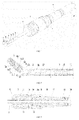
- FIG. 1 is a schematic diagram showing a lateral grinding drill with continuously variable angle according to one embodiment of the present invention
- FIG. 2 is a schematic diagram showing the section of the front end of the lateral grinding drill with continuously variable angle according to one embodiment of the present invention
- FIG. 3 is a schematic diagram showing the section of the back end of the lateral grinding drill with continuously variable angle according to one embodiment of the present invention
- FIG. 4 is a detailed diagram of the portion contained in circle A of FIG. 1
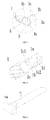
- FIG. 5 is a schematic diagram showing a grinding head according to one embodiment of the present invention
- FIG. 6 is a schematic diagram showing a flexible transmission part according to one embodiment of the present invention.
- the lateral grinding drill with continuously variable angle includes a tube body component and a grinding head 1 arranged at the front end of the tube body component, the grinding head 1 being configured to be driven to pitch and rotate on its own axis
- the tube body component includes an outer tube body 3 and an inner tube body 11 which is coaxially arranged inside the outer tube body 3 and configured to be rotatablely fit with the outer tube body 3 and the grinding head 11, the tail end of the grinding head 1 is articulated to the inner tube body 11 along the circumferential direction in a form of transmission, and a flexible transmission part 13 is arranged at least on the front end of the inner tube body 11 , which is configured to be articulated to the tail end of the grinding head 1 and be able to transmit torque.
- the pitching described here means rotating at a certain angle to the axis of the tube body component.
- the grinding head rotating on its own axis described here means the grinding head is driven to rotate for grinding.
- the grinding head can be adjusted to be coaxial with the tube body component when it is used, and can be adjusted to a position of suitable pitch angle for grinding according to the need after it enters into a working circumstance.
- the grinding head may carry out grinding after pitching.
- the transmission means adapting the change of the transmission axis through the flexible transmission part.
- an articulation groove Id with an opening end is formed at the tail end of the grinding head 1, and the front end of the flexible transmission part 13 is provided with a rod-shaped articulation portion 13a which is configured to be rotatablely fit with the flexible transmission part and articulated and fit with the articulation groove.
- the flexible transmission part 13 In addition to having the flexible transmission part 13 to fit the rotation of the grinding head on its own axis driven after the pitching operation, there is some movement space between the articulation groove Id and the rod-shaped articulation portion 13a to fit the length difference generated after the pitching operation, so the rotation may be smooth, and the inner tube body 11 and the flexible transmission part 13 can be drew form the outer tube body 2 to be convenient for assembly and disassemble.
- the rod-shaped articulation portion 13a and the flexible transmission part 13 form a T-shaped structure. In this way, it may not only ensure the transmission strength of the articulated structure, but also make the outer tube body 3 pass smoothly after its articulated position for pitching has been thickened inwards.
- the articulation portion of such structure can also be available for an articulation groove without an opening.
- the root of the connection between the flexible transmission part and the rod-shaped articulation portion is necking on the T-shaped plane.
- Such structure can be adapted to the structure of the articulation groove and not interfere with the groove wall of the articulation groove Id, when the rod-shaped articulation portion 13a moves laterally and rotationally from the articulation groove Id after the rod-shaped articulation portion 13a being articulated to the articulation groove Id.
- the grinding head 1 is provided with a grinding head handle 1a, and the articulation groove Id is located on the tail end of the grinding head handle 1a.
- the front end of the outer tube body 3 is articulated with a grinding head mount sheath 4 in a single degree of freedom mode
- the grinding head handle 1a is arranged inside the grinding head mount sheath 4 and configure to be rotatablely fit with the grinding head mount sheath 4 in a single degree of freedom mode
- the grinding head 1 has a grinding blade extending out of the grinding head mount sheath 4.
- the fit mode of rotatablely fiting in a single degree of freedom can be any mechanical means which can achieve this structure, including axial mechanical position-limiting.
- the flexible transmission part 13 is connected to the front end of the inner tube body 11 through threaded connection or locking connection, with a good adaptation, and the flexible transmission part can be replaced according to needs to ensure the long-term operation of the tool.
- the rod-shaped articulation portion 13a is integrally formed on the front end of the flexible transmission part 13. The articulation in a single degree of freedom mode means that the relative motion between the parts articulated together is limited in the transmission direction of the articulation, and the means for articulation can be an existing articulated structure with shaft.
- the grinding head handle 1a has axial movement space after being articulated to the flexible transmission part 13, to form a complete open articulated structure which is formed by inserting the rod-shaped articulation portion 13a into the articulation groove Id directly and has axial movement space to make the relative movement between the grinding head handle 1a and the rod-shaped articulation portion 13a smooth, so that the inner tube body 11 and the flexible transmission part 13 can be drawn out at any time to facilitate cleaning and maintenance.
- This structure removes the universal shaft structure of the existing technologies, achieves the compactness of the structure and reduction of the volume, and is more applicable for deep and narrow space.
- the outer tube body is configured to be driven to ratate along the circumferential direction, so that the grinding head mount sheath and grinding head are configured to be driven to revolute.
- the revolution described here means the whole grinding head 1 rotates around the axis of the tube body component in order to achieve universal grinding, that is, pitching motion and circumferential motion can be achieved, as two degrees of freedom, and can be combined to form a plurality of working conditions in different directions.
- the grinding head can be adjusted to be coaxial with the tube body component when it is used, and can be adjusted to a position of suitable pitch angle for grinding according to the need after it enters into a working circumstance.
- the lateral grinding drill with continuously variable angle further includes a connection handle 9 and a driving component
- the driving component includes a pitching driving component for driving the grinding head mount sheath 4 to pitch and a direction driving component for driving the outer tube body to rotate along the circumferential direction.
- the pitching driving component includes a reciprocating middle part and a reciprocating driving part 8, the front end of the reciprocating middle part is connected to the grinding head mount sheath 4 in a form that the grinding head mount sheath 4 is drivable to pitch, in order to drive the grinding head mount sheath 4 to rotate in the pitching articulation direction, to drive the grinding head 1 to implement pitching motion.
- the back end of the reciprocating middle part is drivablely fit with the reciprocating driving part 8 at least in the axial direction, and the reciprocating driving part 8 is fit with the connection handle 9 in a form that the reciprocating driving part 8 is movable relative to the connection handle connection handle 9, in order to drive the reciprocating middle part to implement reciprocating motion to achieve the pitching motion of the grinding head mount sheath 4.
- the reciprocating driving part 8 may be fit with the connection handle 9 in a form that the reciprocating driving part 8 is movable relative to the connection handle connection handle 9, or through thread fitting or in a form of other reciprocating motions and being positioned at any time.
- the direction driving component includes a connection sleeve 6 coaxially fixed to the outer tube body of the grinding tool, and a driving sleeve 7 arranged outside the connection sleeve, the driving sleeve is fixed to the connection sleeve in the circumferential direction and is slidable to the connection sleeve in the axial direction.
- the outer tube body 3 is connected to the connection sleeve 6 by welding.
- the relative sliding of the connection sleeve 6 to the driving sleeve 7 can be achieved by an axial flat key or the cooperation of splines, it is not explained here.
- the driving sleeve 7 is configured to slide along the axial direction to engage with or disengage from the connection handle 9 to achieve limiting or releasing in the circumferential direction.
- the front end of the connection handle 9 can be provided with end face splines
- the tail end of the driving sleeve 7 is also provided with end face splines.
- the driving sleeve 7 can be manually driven to drive the connection sleeve 6 to rotate, so as to drive the outer tube body 3 to rotate, and make the grinding head to implement revolution.
- the function of universal direction can be achieved by combining the revolution with the rotation of the grinding head 1 on its axis and the pitching motion.
- the driving sleeve 7 is provided with a backward pretightening force which makes the driving sleeve 7 be close to the front end of the connection handle 9 and engage with the connection handle 9 in the circumferential direction.
- the pretightening force may be achieved by a spring or snap spring. The engagement is achieved by the pretightening force to avoid the mistake operation and the detachment problem at runtime.
- a spring cavity is arranged on the inner circle of the driving sleeve 7
- a columnar spring is arranged outside of the connection sleeve 6, two ends of the columnar spring press against an outer boss formed on the outer circle of the connection sleeve 6, and an inner boss formed on the inner circle of the driving sleeve 7 respectively.
- the tail end of the reciprocating middle part is axially fixedly connected with a transition sleeve 15
- a radial driving arm 15a is arranged on the outer circle of the transition sleeve 15, and the radial driving arm 15a is configured to be rotatablely fit with the reciprocating driving part 8 in a single degree of freedom mode.
- the radial driving arm 15a is axially fixed through a pressing sleeve 16 matching with the reciprocating driving part 8 in screw thread.
- the reciprocating driving part 8 is a reciprocating driving sleeve with internal threads which match with external threads provided on the connection handle 9.
- a necking portion is arranged on the back end of the driving sleeve, the front end of the reciprocating driving sleeve is arranged outside the outer circle of the necking portion of driving sleeve, and the back end of the reciprocating driving sleeve is arranged outside the connection handle.
- the back end of the driving sleeve 7 is provided with the necking portion, the front end of the reciprocating driving sleeve is arranged outside the outer circle of the necking portion of driving sleeve 7, a step is formed on the inner circle of the front end of the reciprocating driving sleeve, the step is connected to a press cover to form a circular groove.
- the radial driving arm 15a is inserted into the circular groove to form a fitting structure which is fixed in the axial direction and slidable in the circumferential direction.
- two radial driving arms arranged symmetrically can transmit driving force uniformly.
- the radial driving arm is located between the driving sleeve and the connection connection handle 9, and between the driving sleeve and the reciprocating driving sleeve, so the radial driving arm should be kept away from the end face splines between the driving sleeve 7 and the connection handle 9, to avoid motion interference.
- the back end of the reciprocating driving sleeve is arranged outside the connection handle 9, as shown in the figures, the back end of the reciprocating driving sleeve is arranged outside the connection handle and is fit with the connection handle by threads, facilitating the operation.
- the tail end of the lateral grinding drill with continuously variable angle is provided with a connector 10 connected with the power supply, and the inner surface of the connection handle 9 is provided with a support as the supporting transition sleeve 17 shown in FIG. 3 , for supporting the connector 10.
- the front end of the supporting transition sleeve 17 is arranged outside and rotatably fit with the transition sleeve 15, and the back end of the supporting transition sleeve 17 is arranged inside and rotatably fit with the seal transition sleeve 18.
- the seal transition sleeve 18 is in a rotatable fit, and provided with a necessary seal ring and slide bearing, and it is not explained here.
- the present invention also discloses a special embodiment of a lateral grinding drill with continuously variable angle, including a tube body component and a grinding head 1 arranged at the front end of the tube body component, the grinding head being configured to be driven to pitch and rotate on its own axis, the tube body component including an outer tube body 3 and an inner tube body 11 which is coaxially arranged inside the outer tube body 3 and configured to be rotatablely fit with the outer tube body 3 and the grinding head 1, the front end of the outer tube body being articulated with a grinding head mount sheath 4 in a single degree of freedom mode, the grinding head 1 being provided with a grinding head handle 1a, the grinding head handle 1a is provided with a position-limiting ring 1c which is configured to be rotatablely fit with the grinding head handle 1a in a single degree of freedom mode, and the grinding head handle 1a is arranged inside the grinding head mount sheath 4 through the position-limiting ring 1c in an axial position-limiting form.
- the grinding head handle 1a can be inserted into the grinding head mount sheath 4 directly to achieve axial position-limiting.
- the mode of inserting into a circular groove can be mostly used in the form of rotatable fit in a single degree of freedom.
- the grinding head mount sheath 4 includes an outer sleeve and an inner sleeve 4c arranged inside the outer sleeve, the position-limiting ring 1c is provided with two radially symmetric position-limiting bulges 1c1, 1c2, the outer circle of the grinding head handle 1a is provided with an annular position-limiting groove 1b configured to make the position-limiting ring 1c into place and have radical movement space, and the rotatable fit in a single degree of freedom is achieved by inserting the position-limiting ring 1c into the annular position-limiting groove 1b.
- the inner sleeve 4c is provided with two radially symmetric axial opening grooves 4c1, 4c2, the outer sleeve is provided with a position-limiting through hole 4b radially passing through the outer sleeve, and the outer sleeve is an opening sleeve with an axial opening.
- the grinding head handle 1a is arranged inside the inner sleeve 4c, two position-limiting bulges 1c1, 1c2 of the position-limiting ring 1c are fit along the axial opening grooves, one position-limiting bulge 1c1 is inserted into the position-limiting through hole, and the other position-limiting bulge 1c2 abuts on the inner wall of the outer sleeve.
- the outer sleeve of the grinding head mount sheath 4 has an axial opening, so it has radial elasticity to secure the position-limiting ring 1c. As shown in FIG. 2 , the axial opening of the outer sleeve is arranged on the outer sleeve at an angle of 45° to the position-limiting through hole.
- the grinding head handle 1a and the position-limiting ring 1c are arranged inside the inner sleeve 4c together, two position-limiting bulges 1c1, 1c2 are radially limited and compressed, and when the position-limiting ring 1c slides into the installation position, one position-limiting bulge 1c1 is inserted into the position-limiting through hole of the position-limiting bulge 1c1, to achieve axial position-limiting.
- the position-limiting bulge 1c1 in the position-limiting through hole is radially pressed, the position-limiting ring 1c (the position-limiting ring is an opening ring which is convenient to install into the annular position-limiting groove 1b and convenient to deform) itself and the outer sleeve can be deformed, the position-limiting bulge 1c1 can be radially inwardly disengaged from the inside diameter of the position-limiting through hole 4b, and the grinding head handle can be removed.
- the outer sleeve is not only provided with an axial opening, but also provided with a circumferential groove in the circumferential direction.
- the circumferential groove has an opening at the edge of the axial opening groove to reduce difficulty of assembly and disassembly.
- the lateral grinding drill with continuously variable angle according to this embodiment can be combined with the above technical solution for use, to obtain the better effect.
- the present invention also discloses a lateral grinding drill with continuously variable angle, including a tube body component and a grinding head arranged at the front end of the tube body component, the grinding head 1 being configured to be driven to pitch and rotate on its own axis, the tube body component including an outer tube body 3 and an inner tube body 11 which is coaxially arranged inside the outer tube body 3 and configured to be rotatablely fit with the outer tube body 3 and the grinding head 1, the front end of the outer tube body 3 being articulated with a grinding head mount sheath 4 in a single degree of freedom mode, the grinding head 1 being mounted on the grinding head mount sheath 4 and configure to be rotatablely fit with the grinding head mount sheath 4 along the circumferential direction, and the grinding head 1 having a grinding blade extending out of the grinding head mount sheath 4; and the grinding head mount sheath 4 is provided with a reciprocating middle part configured to drive the grinding head mount sheath to pitch in the rotation direction of the articulation, and the reciprocating middle part at least has
- the reciprocating middle part is a middle tube body 12 located between the inner tube body 11 and the outer tube body 3, there is radical movement space between the middle tube body 12 and the inner tube body 11, and between the middle tube body 12 and the outer tube body 3, the radical movement space accommodates the radial displacement caused by the middle tube body when the grinding head mount sheath 4 is pitching; and the front end of the middle tube body 12 extends forward to form a pitching articulation part 5 which is used to be articulated with the grinding head mount sheath, and the pitching articulation part 5 is rigid.
- the middle tube body 12 can use the radical movement space to accommodate the small radical displacement when the grinding head mount sheath is pitching, and the rigid structure of the pitching articulation part can smoothly drive the grinding head mount sheath to pitch.
- the structure is simple and compact to avoid the increase in volume caused by a complex structure, to ensure the success of the surgery.
- the pitching articulation part 5 is rigid, and is a thickened structure.
- the pitching articulation part 5 is formed on a pup joint which is fixedly connected to the middle tube body, and the pitching articulation part 5 can be also formed in the middle tube body directly, which does not affect the purpose of the present invention. Since this embodiment can be combined with the above technical solutions, the rail end of the middle tube body 12 is axially fixedly connected to the above transition sleeve 15, the outer circle of the transition sleeve 15 is provided with a radial driving arm 15a.
- the transition sleeve 15 is connected with the middle tube body 12 by welding, and the transition sleeve 15 and the radial driving arm 15a are formed integrally.
- the radial driving arm 15a is rotatably fit with the reciprocating driving part in a single degree of freedom mode to achieve forward and backward driving. In this way, the structure is simple and compact, and is convenient for assembly and disassembly.
- the present invention also discloses a special embodiment of a lateral grinding drill with continuously variable angle, including a tube body component and a grinding head 1 arranged at the front end of the tube body component, the grinding head being configured to be driven to pitch and rotate on its own axis, the tube body component including an outer tube body 3 and an inner tube body 11 which is coaxially arranged inside the outer tube body 3 and configured to be rotatablely fit with the outer tube body 3 and the grinding head 1, the front end of the outer tube body 3 is provided with a grinding head mount sheath 4 configured to mount the grinding head 1 and drive the grinding head 1 to pitch, the back end of the grinding head mount sheath 4 and the front end of the outer tube body forms an articulated structure of a single degree of freedom in a form that an articulation joint and an articulation groove are interconnected with each other, and a portion of the outer tube body 3 to be articulated with the grinding head mount sheath 4 is thickened.
- Such design make the articulated structure have enough thickness to increase the strength, and there
- the portion of the outer tube body 3 to be articulated with the grinding head mount sheath 4 is provided with an outer tube articulation part 3b for the fixed connection of the front end of the outer tube body 3, and the outer tube body 3 can be connected to the outer tube articulation part 3b through screw threads or by welding, which is not explained here.
- Two curved articulation joints 3a are radially oppositely formed on the front end face 3c of the outer tube articulation part 3b, and two curved articulation grooves 4a are radially oppositely formed on the tail end face of the grinding head mount sheath 4 and configured for inserting the two curved articulation joints 3a to form an articulated structure of a single degree of freedom.
- the outer tube articulation part 3b is located between the two curved articulation joints 3a to form a channel through which the inner tube body 11 passes.
- the outer tube articulation part 3b is thickened in the channel radially inwards.
- the special shape of the head of the inner tube body 11 (including the flexible transmission part 13) is designed so that it can pass through the narrow channel (caused by thickening) between the curved articulation joints, be kept away from the two curved articulation joints and the front grinding head to form a universal joint to rotation drive.
- the articulation joint is thickened, and the connection structure of the outer tube articulation part 3b and the outer tube body 3 is used, so it not only increases the strength, but also facilitates assembly.
- the present invention also discloses a driving component for driving a lateral grinding drill with continuously variable angle to change grinding orientation, including a connection handle 9 and a pitching driving component for driving the grinding head 1 of the lateral grinding drill with continuously variable angle to pitch, wherein the pitching driving component includes a reciprocating middle part and a reciprocating driving part 8, the front end of the reciprocating middle part is connected to the grinding head 1 in a form that the grinding head 1 is drivable to pitch, the back end of the reciprocating middle part is drivablely fit with the reciprocating driving part 8 at least in the axial direction, and the reciprocating driving part 8 is fit with the connection handle 9 in a form that the reciprocating driving part is movable relative to the connection handle connection handle.
- the pitching driving component includes a reciprocating middle part and a reciprocating driving part 8
- the front end of the reciprocating middle part is connected to the grinding head 1 in a form that the grinding head 1 is drivable to pitch
- the back end of the reciprocating middle part is drivablely
- the driving component further includes a direction driving component
- the direction driving component includes a connection sleeve 6 coaxially fixed to the outer tube body 3 of the lateral grinding drill with continuously variable angle, and a driving sleeve 7 arranged outside the connection sleeve 6, the driving sleeve 7 is fixed to the connection sleeve 6 in the circumferential direction and is slidable to the connection sleeve 6 in the axial direction, and the driving sleeve 7 is configured to slide along the axial direction to engage with or disengage from the connection handle 9 to achieve limiting or releasing in the circumferential direction.
- the driving sleeve 7 is provided with a backward pretightening force which makes the driving sleeve 7 be close to the front end of the connection handle 9 and engage with the connection handle 9 in the circumferential direction;
- the tail end of the middle tube is axially fixedly connected with a transition sleeve 15, a radial driving arm 15a is arranged on the outer circle of the transition sleeve 15, and the radial driving arm 15a is configured to be rotatablely fit with the reciprocating driving part 8 in a single degree of freedom mode;
- the reciprocating driving part 8 is a reciprocating driving sleeve with internal threads which match with external threads provided on the connection handle 9; and a necking portion is arranged on the back end of the driving sleeve 7, the front end of the reciprocating driving sleeve is arranged outside the outer circle of the necking portion of driving sleeve 7, and the back end of the reciprocating driving sleeve is arranged outside the connection handle 9.
Landscapes
- Health & Medical Sciences (AREA)
- Life Sciences & Earth Sciences (AREA)
- Surgery (AREA)
- Veterinary Medicine (AREA)
- Animal Behavior & Ethology (AREA)
- General Health & Medical Sciences (AREA)
- Public Health (AREA)
- Oral & Maxillofacial Surgery (AREA)
- Dentistry (AREA)
- Nuclear Medicine, Radiotherapy & Molecular Imaging (AREA)
- Engineering & Computer Science (AREA)
- Biomedical Technology (AREA)
- Heart & Thoracic Surgery (AREA)
- Medical Informatics (AREA)
- Molecular Biology (AREA)
- Orthopedic Medicine & Surgery (AREA)
- Epidemiology (AREA)
- Surgical Instruments (AREA)
- Finish Polishing, Edge Sharpening, And Grinding By Specific Grinding Devices (AREA)
Abstract
Description
- The present invention relates to a medical device, and more particularly, to a lateral grinding drill with continuously variable angle used in orthopedics surgery and a driving component.
- The bone tissue in the body sometimes needs to be grinded in orthopedic surgery. In the prior art, the grinding head is generally driven by a power handle directly to rotate for grinding. Since the grinding head is directly driven by the power handle, and the grinding head is required to extend into the human body, it is difficult to control the grinding head when the grinding head reaches a surgery site that is difficult to observe. Especially when different positions are required to be grinded, the grinding head is hard to be changed to accommodate the positions required to be grinded. Such grinding head is inconvenient to use, causing a low efficiency of the surgery.
- In order to solve the above problem, a flexible grinding head appeared. The grinding head can be controlled to perform pitching action in response to changes in positions required to be grinded. The grinding head has a structure with a universal joint for connecting and driving. The structure is complex and its manufacturing process is also complex. With the structure, the radius of the grinding tool is increased, while the above orthopedic surgery generally requires the whole of the grinding tool have a small external diameter, otherwise the grinding tool cannot reach the surgery position, or motion interference can happen during the surgery. Meanwhile, in the structure, a connection structure with a universal joint can be used to implement pitching motion and rotating transmission between the grinding head and the inner tube, but such structure is complex and cannot be controlled stablely. In addition, the structure can only implement the pitching action, and cannot implement adaptive operations corresponding to the change of the portion required to be grinded in circumferential direction, so that both the grinding tool and the driving handle should change direction integrally, resulting in inconvenience for use. Further, the driving part for driving the pitching action is relatively primitive, which affects the compactness of the grinding tool.
- As a result, there is a requirement to provide a lateral grinding drill with continuously variable angle, which can adjust the position of the grinding head in longitudinal direction and circumferential direction during surgery, have a good adaptability for the surgery position and good accuracy to improve the efficiency in surgery operation, and shorten postoperative recovery time, to alleviate the suffering of the patients while reducing treatment cost. In addition, the whole of the lateral grinding drill with continuously variable angle is detachable, with a simple structure, in which, the transmission chain is short that it is easy for stable control to improve the efficiency of the surgery.
- Based on this, the present invention provide a lateral grinding drill with continuously variable angle, which can adjust the position of the grinding head in longitudinal direction and circumferential direction during surgery, have a good adaptability for the surgery position and good accuracy to improve the efficiency in surgery operation, and shorten postoperative recovery time, to alleviate the suffering of the patients while reducing treatment cost. In addition, the whole of the lateral grinding drill with continuously variable angle is detachable, with a simple structure, in which, the transmission chain is short that it is easy for stable control to improve the efficiency of the surgery.
- The lateral grinding drill with continuously variable angle according to the present invention includes a tube body component and a grinding head arranged at the front end of the tube body component, the grinding head being configured to be driven to pitch and rotate on its own axis, wherein the tube body component includes an outer tube body and an inner tube body which is coaxially arranged inside the outer tube body and configured to be rotatablely fit with the outer tube body and the grinding head, the tail end of the grinding head is articulated to the inner tube body to achieve transmission along the circumferential direction, and a flexible transmission part is arranged at least on the front end of the inner tube body, which is configured to be articulated to the tail end of the grinding head and be able to transmit torque.
- Further, an articulation groove with an opening end is formed at the tail end of the grinding head, and the front end of the flexible transmission part is provided with a rod-shaped articulation portion which is configured to be rotatablely fit with the flexible transmission part and articulated and fit with the articulation groove.
- Further, an articulation groove is formed at the tail end of the grinding head, the front end of the flexible transmission part is provided with a rod-shaped articulation portion which is configured to be rotatablely fit with the flexible transmission part and articulated and fit with the articulation groove, the rod-shaped articulation portion and the flexible transmission part form a T-shaped structure.
- Further, the root of the connection between the flexible transmission part and the rod-shaped articulation portion is necking on the T-shaped plane.
- Further, the grinding head is provided with a grinding head handle, and the articulation groove is located on the tail end of the grinding head handle; the front end of the outer tube body is articulated with a grinding head mount sheath in a single degree of freedom mode, the grinding head handle is arranged inside the grinding head mount sheath and configure to be rotatablely fit with the grinding head mount sheath in a single degree of freedom mode, and the grinding head has a grinding blade extending out of the grinding head mount sheath; and the flexible transmission part is connected to the front end of the inner tube body, and the rod-shaped articulation portion is integrally formed on the front end of the flexible transmission part.
- Further, the outer tube body is configured to be driven to rotate along the circumferential direction, so that the grinding head mount sheath and grinding head are configured to be driven to revolute.
- Further, the lateral grinding drill with continuously variable angle further includes a connection handle and a driving component, and the driving component includes a pitching driving component for driving the grinding head mount sheath to pitch and a direction driving component for driving the outer tube body to rotate along the circumferential direction.
- The pitching driving component includes a reciprocating middle part and a reciprocating driving part, the front end of the reciprocating middle part is connected to the grinding head mount sheath in a form that the grinding head mount sheath is drivable to pitch, the back end of the reciprocating middle part is drivablely fit with the reciprocating driving part at least in the axial direction, and the reciprocating driving part is fit with the connection handle in a form that the reciprocating driving part is movable relative to the connection handle connection handle.
- The direction driving component includes a connection sleeve coaxially fixed to the outer tube body, and a driving sleeve arranged outside the connection sleeve, the driving sleeve is fixed to the connection sleeve in the circumferential direction and is slidable to the connection sleeve in the axial direction, and the driving sleeve is configured to slide along the axial direction to engage with or disengage from the connection handle to achieve limiting or releasing in the circumferential direction.
- Further, the driving sleeve is provided with a backward pretightening force which makes the driving sleeve be close to the front end of the connection handle and engage with the connection handle in the circumferential direction; the tail end of the reciprocating middle part is axially fixedly connected with a transition sleeve, a radial driving arm is arranged on the outer circle of the transition sleeve, and the radial driving arm is configured to be rotatablely fit with the reciprocating driving part in a single degree of freedom mode; the reciprocating driving part is a reciprocating driving sleeve with internal threads which match with external threads provided on the connection handle; and a necking portion is arranged on the back end of the driving sleeve, the front end of the reciprocating driving sleeve is arranged outside the outer circle of the necking portion of driving sleeve, and the back end of the reciprocating driving sleeve is arranged outside the connection handle.
- The present invention also discloses a lateral grinding drill with continuously variable angle, including a tube body component and a grinding head arranged at the front end of the tube body component, the grinding head being configured to be driven to pitch and rotate on its own axis, the tube body component including an outer tube body and an inner tube body which is coaxially arranged inside the outer tube body and configured to be rotatablely fit with the outer tube body and the grinding head, the front end of the outer tube body being articulated with a grinding head mount sheath in a single degree of freedom mode, the grinding head being provided with a grinding head handle, the grinding head handle is provided with a position-limiting ring which is configured to be rotatablely fit with the grinding head handle in a single degree of freedom mode, and the grinding head handle is arranged inside the grinding head mount sheath through the position-limiting ring in an axial position-limiting form.
- Further, the grinding head mount sheath includes an outer sleeve and an inner sleeve arranged inside the outer sleeve, the position-limiting ring is provided with two radially symmetric position-limiting bulges, the outer circle of the grinding head handle is provided with an annular position-limiting groove configured to make the position-limiting ring into place and have extra movement space in radial direction, the inner sleeve is provided with two radially symmetric axial opening grooves, the outer sleeve is provided with a position-limiting through hole radially passing through the outer sleeve, and the outer sleeve is an opening sleeve with an axial opening; and the grinding head handle is arranged inside the inner sleeve, two position-limiting bulges of the position-limiting ring are fit along the axial opening grooves, one of the position-limiting bulges is inserted into the position-limiting through hole, and the other position-limiting bulge abuts on the inner wall of the outer sleeve.
- The present invention also discloses a lateral grinding drill with continuously variable angle, including a tube body component and a grinding head arranged at the front end of the tube body component, the grinding head being configured to be driven to pitch and rotate on its own axis, the tube body component including an outer tube body and an inner tube body which is coaxially arranged inside the outer tube body and configured to be rotatablely fit with the outer tube body and the grinding head, the front end of the outer tube body being articulated with a grinding head mount sheath in a single degree of freedom mode, the grinding head being mounted on the grinding head mount sheath and configure to be rotatablely fit with the grinding head mount sheat along the circumferential direction, and the grinding head having a grinding blade extending out of the grinding head mount sheath; and the grinding head mount sheath is provided with a reciprocating middle part configured to drive the grinding head mount sheath to pitch in the rotation direction of the articulation, and the reciprocating middle part at least has movement space in the direction of the pitching motion of the grinding head mount sheath.
- Further, the reciprocating middle part is a middle tube body located between the inner tube body and the outer tube body, there is radical movement space between the middle tube body and the inner tube body, and between the middle tube body and the outer tube body, the radical movement space accommodates the radial displacement caused by the middle tube body when the grinding head mount sheath is driven to pitch; and the front end of the middle tube body extends forward to form a pitching articulation part which is used to be articulated with the grinding head mount sheath, and the pitching articulation part is rigid.
- The present invention also discloses a lateral grinding drill with continuously variable angle, including a tube body component and a grinding head arranged at the front end of the tube body component, the grinding head being configured to be driven to pitch and rotate on its own axis, the tube body component including an outer tube body and an inner tube body which is coaxially arranged inside the outer tube body and configured to be rotatablely fit with the outer tube body and the grinding head, the front end of the outer tube body is provided with a grinding head mount sheath configured to mount the grinding head and drive the grinding head to pitch, the back end of the grinding head mount sheath and the front end of the outer tube body forms an articulated structure of a single degree of freedom in a form that an articulation joint and an articulation groove are interconnected with each other, and a portion of the outer tube body to be articulated with the grinding head mount sheath is thickened.
- Further, the front end of the outer tube body is fixedly connected with a outer tube articulation part adapted to be articulated with the grinding head mount sheath, two curved articulation joints are radially oppositely formed on the front end face of the outer tube articulation part, and two curved articulation grooves are radially oppositely formed on the tail end face of the grinding head mount sheath and configured for inserting the two curved articulation joints to form an articulated structure of a single degree of freedom; and the outer tube articulation part is located between the two curved articulation joints to form a channel through which the inner tube body passes.
- The present invention also discloses a driving component for driving a lateral grinding drill with continuously variable angle to change grinding orientation, including a connection handle and a pitching driving component for driving the grinding head of the lateral grinding drill with continuously variable angle to pitch, wherein the pitching driving component includes a reciprocating middle part and a reciprocating driving part, the front end of the reciprocating middle part is connected to the grinding head in a form that the grinding head is drivable to pitch, the back end of the reciprocating middle part is drivablely fit with the reciprocating driving part at least in the axial direction, and the reciprocating driving part is fit with the connection handle in a form that the reciprocating driving part is movable relative to the connection handle connection handle.
- Further, the driving component further includes a direction driving component, the direction driving component includes a connection sleeve coaxially fixed to the outer tube body of the lateral grinding drill with continuously variable angle, and a driving sleeve arranged outside the connection sleeve, the driving sleeve is fixed to the connection sleeve in the circumferential direction and is slidable to the connection sleeve in the axial direction, and the driving sleeve is configured to slide along the axial direction to engage with or disengage from the connection handle to achieve limiting or releasing in the circumferential direction.
- Further, the driving sleeve is provided with a backward pretightening force which makes the driving sleeve be close to the front end of the connection handle and engage with the connection handle in the circumferential direction; the tail end of the middle tube is axially fixedly connected with a transition sleeve, a radial driving arm is arranged on the outer circle of the transition sleeve, and the radial driving arm is configured to be rotatablely fit with the reciprocating driving part in a single degree of freedom mode; the reciprocating driving part is a reciprocating driving sleeve with internal threads which match with external threads provided on the connection handle; and a necking portion is arranged on the back end of the driving sleeve, the front end of the reciprocating driving sleeve is arranged outside the outer circle of the necking portion of driving sleeve, and the back end of the reciprocating driving sleeve is arranged outside the connection handle.
- The present invention has the following beneficial effects. The lateral grinding drill with continuously variable angle according to the present invention adopts a direct articulated structure to transmit the transmission between the inner tube body and the grinding head, and can implement pitching motion. A flexible transmission structure is used to compensate the axis deviation caused by the pitching and driving. The transmission structure is simple, and the transmission cycle is short, which facilitates stable control to improve the efficiency of the surgery. In addition, with the structure which can adjust the grinding head in both the pitching and circumferential positions, it achieves the universal direction adjustment of the grinding head, so that the grinding head can be adjusted in the longitudinal and circumferential positions according to the change of the surgery site, which can have a good adaptability for the surgery position and good accuracy to improve the efficiency in surgery operation, and shorten postoperative recovery time, to alleviate the suffering of the patients while reducing treatment cost.
- The present invention will be described below by reference to the following embodiments taken in conjunction with the accompanying drawings.
-
FIG. 1 is a schematic diagram showing a lateral grinding drill with continuously variable angle according to one embodiment of the present invention. -
FIG. 2 is a schematic diagram showing the section of the front end of the lateral grinding drill with continuously variable angle according to one embodiment of the present invention. -
FIG. 3 is a schematic diagram showing the section of the back end of the lateral grinding drill with continuously variable angle according to one embodiment of the present invention. -
FIG. 4 is a detailed diagram of the portion contained in circle A ofFIG. 1 . -
FIG. 5 is a schematic diagram showing a grinding head according to one embodiment of the present invention. -
FIG. 6 is a schematic diagram showing a flexible transmission part according to one embodiment of the present invention. -
FIG. 1 is a schematic diagram showing a lateral grinding drill with continuously variable angle according to one embodiment of the present invention;FIG. 2 is a schematic diagram showing the section of the front end of the lateral grinding drill with continuously variable angle according to one embodiment of the present invention;FIG. 3 is a schematic diagram showing the section of the back end of the lateral grinding drill with continuously variable angle according to one embodiment of the present invention;FIG. 4 is a detailed diagram of the portion contained in circle A ofFIG. 1 ;FIG. 5 is a schematic diagram showing a grinding head according to one embodiment of the present invention; andFIG. 6 is a schematic diagram showing a flexible transmission part according to one embodiment of the present invention. As shown in the figures, the lateral grinding drill with continuously variable angle according to the present invention, i.e., medical grinding tool, includes a tube body component and agrinding head 1 arranged at the front end of the tube body component, the grindinghead 1 being configured to be driven to pitch and rotate on its own axis, wherein the tube body component includes anouter tube body 3 and aninner tube body 11 which is coaxially arranged inside theouter tube body 3 and configured to be rotatablely fit with theouter tube body 3 and thegrinding head 11, the tail end of the grindinghead 1 is articulated to theinner tube body 11 along the circumferential direction in a form of transmission, and aflexible transmission part 13 is arranged at least on the front end of theinner tube body 11 , which is configured to be articulated to the tail end of the grindinghead 1 and be able to transmit torque. The pitching described here means rotating at a certain angle to the axis of the tube body component. The grinding head rotating on its own axis described here means the grinding head is driven to rotate for grinding. The grinding head can be adjusted to be coaxial with the tube body component when it is used, and can be adjusted to a position of suitable pitch angle for grinding according to the need after it enters into a working circumstance. The grinding head may carry out grinding after pitching. The transmission means adapting the change of the transmission axis through the flexible transmission part. - In the embodiment, an articulation groove Id with an opening end is formed at the tail end of the
grinding head 1, and the front end of theflexible transmission part 13 is provided with a rod-shaped articulation portion 13a which is configured to be rotatablely fit with the flexible transmission part and articulated and fit with the articulation groove. In addition to having theflexible transmission part 13 to fit the rotation of the grinding head on its own axis driven after the pitching operation, there is some movement space between the articulation groove Id and the rod-shaped articulation portion 13a to fit the length difference generated after the pitching operation, so the rotation may be smooth, and theinner tube body 11 and theflexible transmission part 13 can be drew form the outer tube body 2 to be convenient for assembly and disassemble. - In the embodiment, the rod-
shaped articulation portion 13a and theflexible transmission part 13 form a T-shaped structure. In this way, it may not only ensure the transmission strength of the articulated structure, but also make theouter tube body 3 pass smoothly after its articulated position for pitching has been thickened inwards. Of course, the articulation portion of such structure can also be available for an articulation groove without an opening. - In the embodiment, the root of the connection between the flexible transmission part and the rod-shaped articulation portion is necking on the T-shaped plane. Such structure can be adapted to the structure of the articulation groove and not interfere with the groove wall of the articulation groove Id, when the rod-shaped
articulation portion 13a moves laterally and rotationally from the articulation groove Id after the rod-shapedarticulation portion 13a being articulated to the articulation groove Id. - In the embodiment, the grinding
head 1 is provided with a grinding head handle 1a, and the articulation groove Id is located on the tail end of the grinding head handle 1a. The front end of theouter tube body 3 is articulated with a grindinghead mount sheath 4 in a single degree of freedom mode, the grinding head handle 1a is arranged inside the grindinghead mount sheath 4 and configure to be rotatablely fit with the grindinghead mount sheath 4 in a single degree of freedom mode, and the grindinghead 1 has a grinding blade extending out of the grindinghead mount sheath 4. The fit mode of rotatablely fiting in a single degree of freedom can be any mechanical means which can achieve this structure, including axial mechanical position-limiting. With the structure of the grinding head handle 1a, it is convenient for installation and assembly, can assure the structure compactness, and is appropriate for this filed, and the grinding head can be driven by the grindinghead mount sheath 4 to implement pitching action. Theflexible transmission part 13 is connected to the front end of theinner tube body 11 through threaded connection or locking connection, with a good adaptation, and the flexible transmission part can be replaced according to needs to ensure the long-term operation of the tool. The rod-shapedarticulation portion 13a is integrally formed on the front end of theflexible transmission part 13. The articulation in a single degree of freedom mode means that the relative motion between the parts articulated together is limited in the transmission direction of the articulation, and the means for articulation can be an existing articulated structure with shaft. Since such structure tends to be small, it is appropriate to provide an articulation groove on a part, and process a rod-shaped structure matching with the articulation groove or two radially symmetric ball structures on another part. As shown inFIG. 4 , twocurved articulation joints 3a are radially oppositely formed on the front end face of theouter tube body 3, and twocurved articulation grooves 4a are radially oppositely formed on the tail end face of the grindinghead mount sheath 4 and configured for inserting the twocurved articulation joints 3a to form an articulated structure of a single degree of freedom. In this way, it is simple in structure, convenient for processing, flexible for the articulation to rotate, and easy to disassemble. In addition, this structure makes the axis of the outer tube body and the axis of the articulation be located on the same plane. - As shown in the figures, the grinding head handle 1a has axial movement space after being articulated to the
flexible transmission part 13, to form a complete open articulated structure which is formed by inserting the rod-shapedarticulation portion 13a into the articulation groove Id directly and has axial movement space to make the relative movement between the grinding head handle 1a and the rod-shapedarticulation portion 13a smooth, so that theinner tube body 11 and theflexible transmission part 13 can be drawn out at any time to facilitate cleaning and maintenance. This structure removes the universal shaft structure of the existing technologies, achieves the compactness of the structure and reduction of the volume, and is more applicable for deep and narrow space. - In the embodiment, the outer tube body is configured to be driven to ratate along the circumferential direction, so that the grinding head mount sheath and grinding head are configured to be driven to revolute. The revolution described here means the whole grinding
head 1 rotates around the axis of the tube body component in order to achieve universal grinding, that is, pitching motion and circumferential motion can be achieved, as two degrees of freedom, and can be combined to form a plurality of working conditions in different directions. The grinding head can be adjusted to be coaxial with the tube body component when it is used, and can be adjusted to a position of suitable pitch angle for grinding according to the need after it enters into a working circumstance. - In the embodiment, the lateral grinding drill with continuously variable angle further includes a
connection handle 9 and a driving component, and the driving component includes a pitching driving component for driving the grindinghead mount sheath 4 to pitch and a direction driving component for driving the outer tube body to rotate along the circumferential direction. - The pitching driving component includes a reciprocating middle part and a
reciprocating driving part 8, the front end of the reciprocating middle part is connected to the grindinghead mount sheath 4 in a form that the grindinghead mount sheath 4 is drivable to pitch, in order to drive the grindinghead mount sheath 4 to rotate in the pitching articulation direction, to drive the grindinghead 1 to implement pitching motion. The back end of the reciprocating middle part is drivablely fit with thereciprocating driving part 8 at least in the axial direction, and thereciprocating driving part 8 is fit with the connection handle 9 in a form that thereciprocating driving part 8 is movable relative to the connection handle connection handle 9, in order to drive the reciprocating middle part to implement reciprocating motion to achieve the pitching motion of the grindinghead mount sheath 4. Thereciprocating driving part 8 may be fit with the connection handle 9 in a form that thereciprocating driving part 8 is movable relative to the connection handle connection handle 9, or through thread fitting or in a form of other reciprocating motions and being positioned at any time. - The direction driving component includes a
connection sleeve 6 coaxially fixed to the outer tube body of the grinding tool, and a drivingsleeve 7 arranged outside the connection sleeve, the driving sleeve is fixed to the connection sleeve in the circumferential direction and is slidable to the connection sleeve in the axial direction. Theouter tube body 3 is connected to theconnection sleeve 6 by welding. The relative sliding of theconnection sleeve 6 to the drivingsleeve 7 can be achieved by an axial flat key or the cooperation of splines, it is not explained here. The drivingsleeve 7 is configured to slide along the axial direction to engage with or disengage from the connection handle 9 to achieve limiting or releasing in the circumferential direction. In this structure, the front end of the connection handle 9 can be provided with end face splines, and the tail end of the drivingsleeve 7 is also provided with end face splines. When the drivingsleeve 7 is driven by external force to axially slide, the drivingsleeve 7 can be manually driven to drive theconnection sleeve 6 to rotate, so as to drive theouter tube body 3 to rotate, and make the grinding head to implement revolution. The function of universal direction can be achieved by combining the revolution with the rotation of the grindinghead 1 on its axis and the pitching motion. - In the embodiment, the driving
sleeve 7 is provided with a backward pretightening force which makes the drivingsleeve 7 be close to the front end of theconnection handle 9 and engage with the connection handle 9 in the circumferential direction. The pretightening force may be achieved by a spring or snap spring. The engagement is achieved by the pretightening force to avoid the mistake operation and the detachment problem at runtime. As shown in the figures, a spring cavity is arranged on the inner circle of the drivingsleeve 7, a columnar spring is arranged outside of theconnection sleeve 6, two ends of the columnar spring press against an outer boss formed on the outer circle of theconnection sleeve 6, and an inner boss formed on the inner circle of the drivingsleeve 7 respectively. The tail end of the reciprocating middle part is axially fixedly connected with atransition sleeve 15, aradial driving arm 15a is arranged on the outer circle of thetransition sleeve 15, and theradial driving arm 15a is configured to be rotatablely fit with thereciprocating driving part 8 in a single degree of freedom mode. As shown in the figures, theradial driving arm 15a is axially fixed through apressing sleeve 16 matching with thereciprocating driving part 8 in screw thread. Thereciprocating driving part 8 is a reciprocating driving sleeve with internal threads which match with external threads provided on theconnection handle 9. A necking portion is arranged on the back end of the driving sleeve, the front end of the reciprocating driving sleeve is arranged outside the outer circle of the necking portion of driving sleeve, and the back end of the reciprocating driving sleeve is arranged outside the connection handle. Through rotating the reciprocating driving sleeve and driving theradial driving arm 15a to implement reciprocating motion, it can achieve smooth and accurate operations to avoid pause and transition in the existing technologies. Meanwhile, the screw thread fitting makes the components have compactedness and integrity. The back end of the drivingsleeve 7 is provided with the necking portion, the front end of the reciprocating driving sleeve is arranged outside the outer circle of the necking portion of drivingsleeve 7, a step is formed on the inner circle of the front end of the reciprocating driving sleeve, the step is connected to a press cover to form a circular groove. As shown in the figures, theradial driving arm 15a is inserted into the circular groove to form a fitting structure which is fixed in the axial direction and slidable in the circumferential direction. Of course, there may be a plurality ofradial driving arms 15a arranged along the circumferential direction. As shown in the figures, two radial driving arms arranged symmetrically can transmit driving force uniformly. The radial driving arm is located between the driving sleeve and theconnection connection handle 9, and between the driving sleeve and the reciprocating driving sleeve, so the radial driving arm should be kept away from the end face splines between the drivingsleeve 7 and theconnection handle 9, to avoid motion interference. The back end of the reciprocating driving sleeve is arranged outside theconnection handle 9, as shown in the figures, the back end of the reciprocating driving sleeve is arranged outside the connection handle and is fit with the connection handle by threads, facilitating the operation. - The tail end of the lateral grinding drill with continuously variable angle is provided with a
connector 10 connected with the power supply, and the inner surface of theconnection handle 9 is provided with a support as the supportingtransition sleeve 17 shown inFIG. 3 , for supporting theconnector 10. The front end of the supportingtransition sleeve 17 is arranged outside and rotatably fit with thetransition sleeve 15, and the back end of the supportingtransition sleeve 17 is arranged inside and rotatably fit with theseal transition sleeve 18. Theseal transition sleeve 18 is in a rotatable fit, and provided with a necessary seal ring and slide bearing, and it is not explained here. - The present invention also discloses a special embodiment of a lateral grinding drill with continuously variable angle, including a tube body component and a grinding
head 1 arranged at the front end of the tube body component, the grinding head being configured to be driven to pitch and rotate on its own axis, the tube body component including anouter tube body 3 and aninner tube body 11 which is coaxially arranged inside theouter tube body 3 and configured to be rotatablely fit with theouter tube body 3 and the grindinghead 1, the front end of the outer tube body being articulated with a grindinghead mount sheath 4 in a single degree of freedom mode, the grindinghead 1 being provided with a grinding head handle 1a, the grinding head handle 1a is provided with a position-limiting ring 1c which is configured to be rotatablely fit with the grinding head handle 1a in a single degree of freedom mode, and the grinding head handle 1a is arranged inside the grindinghead mount sheath 4 through the position-limiting ring 1c in an axial position-limiting form. In this way, the structure is simple, and is easy for disassembly and assembly. The grinding head handle 1a can be inserted into the grindinghead mount sheath 4 directly to achieve axial position-limiting. The mode of inserting into a circular groove can be mostly used in the form of rotatable fit in a single degree of freedom. - In the embodiment, the grinding
head mount sheath 4 includes an outer sleeve and an inner sleeve 4c arranged inside the outer sleeve, the position-limiting ring 1c is provided with two radially symmetric position-limiting bulges 1c1, 1c2, the outer circle of the grinding head handle 1a is provided with an annular position-limiting groove 1b configured to make the position-limiting ring 1c into place and have radical movement space, and the rotatable fit in a single degree of freedom is achieved by inserting the position-limiting ring 1c into the annular position-limiting groove 1b. The inner sleeve 4c is provided with two radially symmetric axial opening grooves 4c1, 4c2, the outer sleeve is provided with a position-limiting throughhole 4b radially passing through the outer sleeve, and the outer sleeve is an opening sleeve with an axial opening. The grinding head handle 1a is arranged inside the inner sleeve 4c, two position-limiting bulges 1c1, 1c2 of the position-limiting ring 1c are fit along the axial opening grooves, one position-limiting bulge 1c1 is inserted into the position-limiting through hole, and the other position-limiting bulge 1c2 abuts on the inner wall of the outer sleeve. The outer sleeve of the grindinghead mount sheath 4 has an axial opening, so it has radial elasticity to secure the position-limiting ring 1c. As shown inFIG. 2 , the axial opening of the outer sleeve is arranged on the outer sleeve at an angle of 45° to the position-limiting through hole. When installing, the grinding head handle 1a and the position-limiting ring 1c are arranged inside the inner sleeve 4c together, two position-limiting bulges 1c1, 1c2 are radially limited and compressed, and when the position-limiting ring 1c slides into the installation position, one position-limiting bulge 1c1 is inserted into the position-limiting through hole of the position-limiting bulge 1c1, to achieve axial position-limiting. When removing, the position-limiting bulge 1c1 in the position-limiting through hole is radially pressed, the position-limiting ring 1c (the position-limiting ring is an opening ring which is convenient to install into the annular position-limiting groove 1b and convenient to deform) itself and the outer sleeve can be deformed, the position-limiting bulge 1c1 can be radially inwardly disengaged from the inside diameter of the position-limiting throughhole 4b, and the grinding head handle can be removed. As shown in the figures, the outer sleeve is not only provided with an axial opening, but also provided with a circumferential groove in the circumferential direction. The circumferential groove has an opening at the edge of the axial opening groove to reduce difficulty of assembly and disassembly. - The lateral grinding drill with continuously variable angle according to this embodiment can be combined with the above technical solution for use, to obtain the better effect.
- The present invention also discloses a lateral grinding drill with continuously variable angle, including a tube body component and a grinding head arranged at the front end of the tube body component, the grinding head 1 being configured to be driven to pitch and rotate on its own axis, the tube body component including an outer tube body 3 and an inner tube body 11 which is coaxially arranged inside the outer tube body 3 and configured to be rotatablely fit with the outer tube body 3 and the grinding head 1, the front end of the outer tube body 3 being articulated with a grinding head mount sheath 4 in a single degree of freedom mode, the grinding head 1 being mounted on the grinding head mount sheath 4 and configure to be rotatablely fit with the grinding head mount sheath 4 along the circumferential direction, and the grinding head 1 having a grinding blade extending out of the grinding head mount sheath 4; and the grinding head mount sheath 4 is provided with a reciprocating middle part configured to drive the grinding head mount sheath to pitch in the rotation direction of the articulation, and the reciprocating middle part at least has movement space in the direction of the pitching motion of the grinding head mount sheath, to accommodate the radial movement of the reciprocating driving part caused by the pitching motion of the grinding head mount sheath 4 after being articulated directly, to avoid interference. In this way, the structure is simple and useful.
- In the embodiment, the reciprocating middle part is a
middle tube body 12 located between theinner tube body 11 and theouter tube body 3, there is radical movement space between themiddle tube body 12 and theinner tube body 11, and between themiddle tube body 12 and theouter tube body 3, the radical movement space accommodates the radial displacement caused by the middle tube body when the grindinghead mount sheath 4 is pitching; and the front end of themiddle tube body 12 extends forward to form apitching articulation part 5 which is used to be articulated with the grinding head mount sheath, and the pitchingarticulation part 5 is rigid. In this way, themiddle tube body 12 can use the radical movement space to accommodate the small radical displacement when the grinding head mount sheath is pitching, and the rigid structure of the pitching articulation part can smoothly drive the grinding head mount sheath to pitch. The structure is simple and compact to avoid the increase in volume caused by a complex structure, to ensure the success of the surgery. As shown in the figures, the pitchingarticulation part 5 is rigid, and is a thickened structure. - The pitching
articulation part 5 is formed on a pup joint which is fixedly connected to the middle tube body, and the pitchingarticulation part 5 can be also formed in the middle tube body directly, which does not affect the purpose of the present invention. Since this embodiment can be combined with the above technical solutions, the rail end of themiddle tube body 12 is axially fixedly connected to theabove transition sleeve 15, the outer circle of thetransition sleeve 15 is provided with aradial driving arm 15a. In the embodiment, thetransition sleeve 15 is connected with themiddle tube body 12 by welding, and thetransition sleeve 15 and theradial driving arm 15a are formed integrally. Theradial driving arm 15a is rotatably fit with the reciprocating driving part in a single degree of freedom mode to achieve forward and backward driving. In this way, the structure is simple and compact, and is convenient for assembly and disassembly. - The present invention also discloses a special embodiment of a lateral grinding drill with continuously variable angle, including a tube body component and a grinding
head 1 arranged at the front end of the tube body component, the grinding head being configured to be driven to pitch and rotate on its own axis, the tube body component including anouter tube body 3 and aninner tube body 11 which is coaxially arranged inside theouter tube body 3 and configured to be rotatablely fit with theouter tube body 3 and the grindinghead 1, the front end of theouter tube body 3 is provided with a grindinghead mount sheath 4 configured to mount the grindinghead 1 and drive the grindinghead 1 to pitch, the back end of the grindinghead mount sheath 4 and the front end of the outer tube body forms an articulated structure of a single degree of freedom in a form that an articulation joint and an articulation groove are interconnected with each other, and a portion of theouter tube body 3 to be articulated with the grindinghead mount sheath 4 is thickened. Such design make the articulated structure have enough thickness to increase the strength, and there is a narrow passage in the middle of the articulated structure. The thickened structure facilitates the bending portion to bear greater lateral bending moment during grinding, to ensure the success of the surgery. - In the embodiment, the portion of the
outer tube body 3 to be articulated with the grindinghead mount sheath 4 is provided with an outertube articulation part 3b for the fixed connection of the front end of theouter tube body 3, and theouter tube body 3 can be connected to the outertube articulation part 3b through screw threads or by welding, which is not explained here. Twocurved articulation joints 3a are radially oppositely formed on thefront end face 3c of the outertube articulation part 3b, and twocurved articulation grooves 4a are radially oppositely formed on the tail end face of the grindinghead mount sheath 4 and configured for inserting the twocurved articulation joints 3a to form an articulated structure of a single degree of freedom. The outertube articulation part 3b is located between the twocurved articulation joints 3a to form a channel through which theinner tube body 11 passes. The outertube articulation part 3b is thickened in the channel radially inwards. The special shape of the head of the inner tube body 11 (including the flexible transmission part 13) is designed so that it can pass through the narrow channel (caused by thickening) between the curved articulation joints, be kept away from the two curved articulation joints and the front grinding head to form a universal joint to rotation drive. In this structure, the articulation joint is thickened, and the connection structure of the outertube articulation part 3b and theouter tube body 3 is used, so it not only increases the strength, but also facilitates assembly. - The present invention also discloses a driving component for driving a lateral grinding drill with continuously variable angle to change grinding orientation, including a
connection handle 9 and a pitching driving component for driving the grindinghead 1 of the lateral grinding drill with continuously variable angle to pitch, wherein the pitching driving component includes a reciprocating middle part and areciprocating driving part 8, the front end of the reciprocating middle part is connected to the grindinghead 1 in a form that the grindinghead 1 is drivable to pitch, the back end of the reciprocating middle part is drivablely fit with thereciprocating driving part 8 at least in the axial direction, and thereciprocating driving part 8 is fit with the connection handle 9 in a form that the reciprocating driving part is movable relative to the connection handle connection handle. - Further, the driving component further includes a direction driving component, the direction driving component includes a
connection sleeve 6 coaxially fixed to theouter tube body 3 of the lateral grinding drill with continuously variable angle, and a drivingsleeve 7 arranged outside theconnection sleeve 6, the drivingsleeve 7 is fixed to theconnection sleeve 6 in the circumferential direction and is slidable to theconnection sleeve 6 in the axial direction, and the drivingsleeve 7 is configured to slide along the axial direction to engage with or disengage from the connection handle 9 to achieve limiting or releasing in the circumferential direction. - Further, the driving
sleeve 7 is provided with a backward pretightening force which makes the drivingsleeve 7 be close to the front end of theconnection handle 9 and engage with the connection handle 9 in the circumferential direction; the tail end of the middle tube is axially fixedly connected with atransition sleeve 15, aradial driving arm 15a is arranged on the outer circle of thetransition sleeve 15, and theradial driving arm 15a is configured to be rotatablely fit with thereciprocating driving part 8 in a single degree of freedom mode; thereciprocating driving part 8 is a reciprocating driving sleeve with internal threads which match with external threads provided on theconnection handle 9; and a necking portion is arranged on the back end of the drivingsleeve 7, the front end of the reciprocating driving sleeve is arranged outside the outer circle of the necking portion of drivingsleeve 7, and the back end of the reciprocating driving sleeve is arranged outside theconnection handle 9. - Each of the above preferred embodiments of the present invention can form a single technical solution, and it should be understood for those skilled in the art that all the above preferred embodiments can be combined to achieve the purpose of the present invention, that is, the aforementioned structures can be independently formed a technical solution or be combined to be applied in the lateral grinding drill of the present invention, which is not explained here.
- The above are preferred embodiments of the present invention described in detail, and should not be deemed as limitations to the scope of the present invention. It should be noted that variations and improvements will become apparent to those skilled in the art to which the present invention pertains without departing from its spirit and scope. Therefore, the scope of the present invention is defined by the appended claims.
Claims (17)
- A lateral grinding drill with continuously variable angle, comprising a tube body component and a grinding head arranged at the front end of the tube body component, the grinding head being configured to be driven to pitch and rotate on its own axis, wherein the tube body component comprises an outer tube body and an inner tube body which is coaxially arranged inside the outer tube body and configured to be rotatablely fit with the outer tube body and the grinding head, the tail end of the grinding head is articulated to the inner tube body along the circumferential direction in a form of transmission, and a flexible transmission part is arranged at least on the front end of the inner tube body, which is configured to be articulated to the tail end of the grinding head and be able to transmit torque.
- The lateral grinding drill with continuously variable angle of claim 1, wherein an articulation groove with an opening end is formed at the tail end of the grinding head, and the front end of the flexible transmission part is provided with a rod-shaped articulation portion which is configured to be rotatablely fit with the flexible transmission part and articulated and fit with the articulation groove.
- The lateral grinding drill with continuously variable angle of claim 1, wherein an articulation groove is formed at the tail end of the grinding head, the front end of the flexible transmission part is provided with a rod-shaped articulation portion which is configured to be rotatablely fit with the flexible transmission part and articulated and fit with the articulation groove, the rod-shaped articulation portion and the flexible transmission part form a T-shaped structure.
- The lateral grinding drill with continuously variable angle of claim 3, wherein the root of the connection between the flexible transmission part and the rod-shaped articulation portion is necking on the T-shaped plane.
- The lateral grinding drill with continuously variable angle of claim 2 or 3, wherein the grinding head is provided with a grinding head handle, and the articulation groove is located on the tail end of the grinding head handle; the front end of the outer tube body is articulated with a grinding head mount sheath in a single degree of freedom mode, the grinding head handle is arranged inside the grinding head mount sheath and configure to be rotatablely fit with the grinding head mount sheath in a single degree of freedom mode, and the grinding head has a grinding blade extending out of the grinding head mount sheath; and the flexible transmission part is connected to the front end of the inner tube body, and the rod-shaped articulation portion is integrally formed on the front end of the flexible transmission part.
- The lateral grinding drill with continuously variable angle of claim 5, wherein the outer tube body is configured to be driven to rotate along the circumferential direction, so that the grinding head mount sheath and grinding head are configured to be driven to revolute.
- The lateral grinding drill with continuously variable angle of claim 6, further comprises a connection handle and a driving component, wherein driving component comprises a pitching driving component for driving the grinding head mount sheath to pitch and a direction driving component for driving the outer tube body to rotate along the circumferential direction;
the pitching driving component comprises a reciprocating middle part and a reciprocating driving part, the front end of the reciprocating middle part is connected to the grinding head mount sheath in a form that the grinding head mount sheath is drivable to pitch, the back end of the reciprocating middle part is drivablely fit with the reciprocating driving part at least in the axial direction, and the reciprocating driving part is fit with the connection handle in a form that the reciprocating driving part is movable relative to the connection handle connection handle; and
the direction driving component comprises a connection sleeve coaxially fixed to the outer tube body, and a driving sleeve arranged outside the connection sleeve, the driving sleeve is fixed to the connection sleeve in the circumferential direction and is slidable to the connection sleeve in the axial direction, and the driving sleeve is configured to slide along the axial direction to engage with or disengage from the connection handle to achieve limiting or releasing in the circumferential direction. - The lateral grinding drill with continuously variable angle of claim 7, wherein the driving sleeve is provided with a backward pretightening force which makes the driving sleeve be close to the front end of the connection handle and engage with the connection handle in the circumferential direction; the tail end of the reciprocating middle part is axially fixedly connected with a transition sleeve, a radial driving arm is arranged on the outer circle of the transition sleeve, and the radial driving arm is configured to be rotatablely fit with the reciprocating driving part in a single degree of freedom mode; the reciprocating driving part is a reciprocating driving sleeve with internal threads which match with external threads provided on the connection handle; and a necking portion is arranged on the back end of the driving sleeve, the front end of the reciprocating driving sleeve is arranged outside the outer circle of the necking portion of driving sleeve, and the back end of the reciprocating driving sleeve is arranged outside the connection handle.
- A lateral grinding drill with continuously variable angle, comprising a tube body component and a grinding head arranged at the front end of the tube body component, the grinding head being configured to be driven to pitch and rotate on its own axis, the tube body component including an outer tube body and an inner tube body which is coaxially arranged inside the outer tube body and configured to be rotatablely fit with the outer tube body and the grinding head, the front end of the outer tube body being articulated with a grinding head mount sheath in a single degree of freedom mode, the grinding head being provided with a grinding head handle, the grinding head handle is provided with a position-limiting ring which is configured to be rotatablely fit with the grinding head handle in a single degree of freedom mode, and the grinding head handle is arranged inside the grinding head mount sheath through the position-limiting ring in an axial position-limiting form.
- The lateral grinding drill with continuously variable angle of claim 9, wherein the grinding head mount sheath comprises an outer sleeve and an inner sleeve arranged inside the outer sleeve, the position-limiting ring is provided with two radially symmetric position-limiting bulges, the outer circle of the grinding head handle is provided with an annular position-limiting groove configured to make the position-limiting ring into place and have radical movement space, the inner sleeve is provided with two radially symmetric axial opening grooves, the outer sleeve is provided with a position-limiting through hole radially passing through the outer sleeve, and the outer sleeve is an opening sleeve with an axial opening; and the grinding head handle is arranged inside the inner sleeve, two position-limiting bulges of the position-limiting ring are fit along the axial opening grooves, one of the position-limiting bulges is inserted into the position-limiting through hole, and the other position-limiting bulge abuts on the inner wall of the outer sleeve.
- A lateral grinding drill with continuously variable angle, comprising a tube body component and a grinding head arranged at the front end of the tube body component, the grinding head being configured to be driven to pitch and rotate on its own axis, the tube body component including an outer tube body and an inner tube body which is coaxially arranged inside the outer tube body and configured to be rotatablely fit with the outer tube body and the grinding head, the front end of the outer tube body being articulated with a grinding head mount sheath in a single degree of freedom mode, the grinding head being mounted on the grinding head mount sheath and configure to be rotatablely fit with the grinding head mount sheat along the circumferential direction, and the grinding head having a grinding blade extending out of the grinding head mount sheath; and the grinding head mount sheath is provided with a reciprocating middle part configured to drive the grinding head mount sheath to pitch in the rotation direction of the articulation, and the reciprocating middle part at least has movement space in the direction of the pitching motion of the grinding head mount sheath.
- The lateral grinding drill with continuously variable angle of claim 11, wherein the reciprocating middle part is a middle tube body located between the inner tube body and the outer tube body, there is radical movement space between the middle tube body and the inner tube body, and between the middle tube body and the outer tube body, the radical movement space accommodates the radial displacement caused by the middle tube body when the grinding head mount sheath is driven to pitch; and the front end of the middle tube body extends forward to form a pitching articulation part which is used to be articulated with the grinding head mount sheath, and the pitching articulation part is rigid.
- A lateral grinding drill with continuously variable angle, comprising a tube body component and a grinding head arranged at the front end of the tube body component, the grinding head being configured to be driven to pitch and rotate on its own axis, the tube body component including an outer tube body and an inner tube body which is coaxially arranged inside the outer tube body and configured to be rotatablely fit with the outer tube body and the grinding head, the front end of the outer tube body is provided with a grinding head mount sheath configured to mount the grinding head and drive the grinding head to pitch, the back end of the grinding head mount sheath and the front end of the outer tube body forms an articulated structure of a single degree of freedom in a form that an articulation joint and an articulation groove are interconnected with each other, and a portion of the outer tube body to be articulated with the grinding head mount sheath is thickened.
- The lateral grinding drill with continuously variable angle of claim 13, wherein the portion of the outer tube body to be articulated with the grinding head mount sheath is provided with an outer tube articulation part for the fixed connection of the front end of the outer tube body, two curved articulation joints are radially oppositely formed on the front end face of the outer tube articulation part, and two curved articulation grooves are radially oppositely formed on the tail end face of the grinding head mount sheath and configured for inserting the two curved articulation joints to form an articulated structure of a single degree of freedom; and the outer tube articulation part is located between the two curved articulation joints to form a channel through which the inner tube body passes, and the thickening of the outer tube articulation part is radially inward in the channel.
- A driving component for driving a lateral grinding drill with continuously variable angle to change grinding orientation, comprising a connection handle and a pitching driving component for driving the grinding head of the lateral grinding drill with continuously variable angle to pitch, wherein the pitching driving component comprises a reciprocating middle part and a reciprocating driving part, the front end of the reciprocating middle part is connected to the grinding head in a form that the grinding head is drivable to pitch, the back end of the reciprocating middle part is drivablely fit with the reciprocating driving part at least in the axial direction, and the reciprocating driving part is fit with the connection handle in a form that the reciprocating driving part is movable relative to the connection handle connection handle.
- The driving component of claim 15, further comprises a direction driving component, the direction driving component comprises a connection sleeve coaxially fixed to the outer tube body of the lateral grinding drill with continuously variable angle, and a driving sleeve arranged outside the connection sleeve, the driving sleeve is fixed to the connection sleeve in the circumferential direction and is slidable to the connection sleeve in the axial direction, and the driving sleeve is configured to slide along the axial direction to engage with or disengage from the connection handle to achieve limiting or releasing in the circumferential direction.
- The driving component of claim 16, wherein the driving sleeve is provided with a backward pretightening force which makes the driving sleeve be close to the front end of the connection handle and engage with the connection handle in the circumferential direction; the tail end of the middle tube is axially fixedly connected with a transition sleeve, a radial driving arm is arranged on the outer circle of the transition sleeve, and the radial driving arm is configured to be rotatablely fit with the reciprocating driving part in a single degree of freedom mode; the reciprocating driving part is a reciprocating driving sleeve with internal threads which match with external threads provided on the connection handle; and a necking portion is arranged on the back end of the driving sleeve, the front end of the reciprocating driving sleeve is arranged outside the outer circle of the necking portion of driving sleeve, and the back end of the reciprocating driving sleeve is arranged outside the connection handle.
Priority Applications (2)
| Application Number | Priority Date | Filing Date | Title |
|---|---|---|---|
| EP17179220.3A EP3260062B1 (en) | 2013-11-29 | 2014-09-26 | Lateral grinding drill with continuously variable angle and driving component thereof |
| EP17179219.5A EP3260061B1 (en) | 2013-11-29 | 2014-09-26 | Lateral grinding drill with continuously variable angle and driving component thereof |
Applications Claiming Priority (4)
| Application Number | Priority Date | Filing Date | Title |
|---|---|---|---|
| CN201310632414 | 2013-11-29 | ||
| CN201310641876.XA CN104605913B (en) | 2013-11-29 | 2013-12-03 | Medical grinding knife tool |
| CN201410041760.7A CN103767759B (en) | 2014-01-28 | 2014-01-28 | Medical grinding cutter |
| PCT/CN2014/087552 WO2015078229A1 (en) | 2013-11-29 | 2014-09-26 | Electrodeless variable angle sideways drill grinding head and drive components thereof |
Related Child Applications (4)
| Application Number | Title | Priority Date | Filing Date |
|---|---|---|---|
| EP17179219.5A Division EP3260061B1 (en) | 2013-11-29 | 2014-09-26 | Lateral grinding drill with continuously variable angle and driving component thereof |
| EP17179219.5A Division-Into EP3260061B1 (en) | 2013-11-29 | 2014-09-26 | Lateral grinding drill with continuously variable angle and driving component thereof |
| EP17179220.3A Division EP3260062B1 (en) | 2013-11-29 | 2014-09-26 | Lateral grinding drill with continuously variable angle and driving component thereof |
| EP17179220.3A Division-Into EP3260062B1 (en) | 2013-11-29 | 2014-09-26 | Lateral grinding drill with continuously variable angle and driving component thereof |
Publications (3)
| Publication Number | Publication Date |
|---|---|
| EP3000417A1 true EP3000417A1 (en) | 2016-03-30 |
| EP3000417A4 EP3000417A4 (en) | 2017-01-18 |
| EP3000417B1 EP3000417B1 (en) | 2018-09-19 |
Family
ID=53198402
Family Applications (3)
| Application Number | Title | Priority Date | Filing Date |
|---|---|---|---|
| EP17179219.5A Active EP3260061B1 (en) | 2013-11-29 | 2014-09-26 | Lateral grinding drill with continuously variable angle and driving component thereof |
| EP14866116.8A Active EP3000417B1 (en) | 2013-11-29 | 2014-09-26 | Electrodeless variable angle sideways drill grinding head and drive components thereof |
| EP17179220.3A Active EP3260062B1 (en) | 2013-11-29 | 2014-09-26 | Lateral grinding drill with continuously variable angle and driving component thereof |
Family Applications Before (1)
| Application Number | Title | Priority Date | Filing Date |
|---|---|---|---|
| EP17179219.5A Active EP3260061B1 (en) | 2013-11-29 | 2014-09-26 | Lateral grinding drill with continuously variable angle and driving component thereof |
Family Applications After (1)
| Application Number | Title | Priority Date | Filing Date |
|---|---|---|---|
| EP17179220.3A Active EP3260062B1 (en) | 2013-11-29 | 2014-09-26 | Lateral grinding drill with continuously variable angle and driving component thereof |
Country Status (6)
| Country | Link |
|---|---|
| US (1) | US10178998B2 (en) |
| EP (3) | EP3260061B1 (en) |
| JP (3) | JP6227159B2 (en) |
| KR (3) | KR101740976B1 (en) |
| ES (1) | ES2775187T3 (en) |
| WO (1) | WO2015078229A1 (en) |
Cited By (1)
| Publication number | Priority date | Publication date | Assignee | Title |
|---|---|---|---|---|
| EP3525683A4 (en) * | 2016-10-21 | 2020-07-29 | University of Louisville Research Foundation, Inc. | Systems and methods for intramedullary preparations |
Families Citing this family (23)
| Publication number | Priority date | Publication date | Assignee | Title |
|---|---|---|---|---|
| CN107072673A (en) | 2014-07-14 | 2017-08-18 | Kb医疗公司 | Anti-skidding operating theater instruments for preparing hole in bone tissue |
| US10765438B2 (en) | 2014-07-14 | 2020-09-08 | KB Medical SA | Anti-skid surgical instrument for use in preparing holes in bone tissue |
| KR102547935B1 (en) * | 2016-06-24 | 2023-06-27 | 삼성디스플레이 주식회사 | Grinding device for substrate |
| EP3603388A4 (en) | 2017-03-31 | 2020-12-16 | NTT Technocross Corporation | Behavior specifying device, behavior specifying method and program |
| WO2019032729A1 (en) * | 2017-08-10 | 2019-02-14 | Pro-Dex, Inc. | Articulating tool for endoscopic placement of fasteners |
| DE102017010033A1 (en) * | 2017-10-27 | 2019-05-02 | Joimax Gmbh | Medical device |
| CN108261225B (en) * | 2018-03-12 | 2024-05-14 | 武汉多可特医疗器械有限公司 | Medical bending and grinding machine head with LED lamp |
| KR102089782B1 (en) * | 2018-05-02 | 2020-03-16 | 고려대학교 산학협력단 | Surgical awl |
| DE202019105420U1 (en) * | 2019-10-01 | 2019-11-13 | Richard Wolf Gmbh | Endoscopic instrument |
| CN110978295A (en) * | 2019-12-31 | 2020-04-10 | 三一汽车制造有限公司 | Milling device and wet spraying machine |
| CN113303864B (en) * | 2020-06-30 | 2023-03-14 | 重庆西山科技股份有限公司 | Elbow pipe grinding tool with angle-adjustable tool bit |
| CN113069199B (en) * | 2021-03-29 | 2022-04-29 | 温州医科大学附属第二医院(温州医科大学附属育英儿童医院) | Clamping device for kirschner wire |
| CN113456164B (en) * | 2021-06-30 | 2023-04-25 | 重庆西山科技股份有限公司 | Direction-changing grinding tool with bending part and compound surgical instrument |
| DE102021119386A1 (en) | 2021-07-27 | 2023-02-02 | Aesculap Ag | Bendable shaft for a medical hand instrument |
| CN113558718B (en) * | 2021-07-31 | 2023-11-03 | 任晓东 | External shock wave therapeutic device |
| CN113855115B (en) * | 2021-10-29 | 2023-06-09 | 温州医科大学附属第一医院 | Connecting rod type endoscopic instrument with changeable angle |
| CN114129200B (en) * | 2021-12-07 | 2024-03-26 | 山东威瑞外科医用制品有限公司 | Clamp head handle |
| DE102022107972A1 (en) | 2022-04-04 | 2023-10-05 | Aesculap Ag | Medical tool system |
| DE102022107970A1 (en) | 2022-04-04 | 2023-10-05 | Aesculap Ag | Flexible surgical tool with integrated bearing assembly |
| CN114831680A (en) * | 2022-06-02 | 2022-08-02 | 北京天星博迈迪医疗器械有限公司 | Full suture anchor implantation device |
| DE102022119983A1 (en) | 2022-08-09 | 2024-02-15 | Aesculap Ag | Medical motor handpiece with angle adjusting ring and medical hand instrument |
| DE102022119979A1 (en) | 2022-08-09 | 2024-02-15 | Aesculap Ag | Medical motor handpiece for 2-in-1 operation and medical hand instrument with 2-in-1 operation |
| DE102022119982A1 (en) | 2022-08-09 | 2024-02-15 | Aesculap Ag | Motor handpiece with rotatable control element and medical hand instrument |
Family Cites Families (23)
| Publication number | Priority date | Publication date | Assignee | Title |
|---|---|---|---|---|
| JPH01119241A (en) | 1987-10-30 | 1989-05-11 | Olympus Optical Co Ltd | Surgical incision instrument |
| US5752973A (en) | 1994-10-18 | 1998-05-19 | Archimedes Surgical, Inc. | Endoscopic surgical gripping instrument with universal joint jaw coupler |
| AU4569697A (en) * | 1997-10-28 | 1999-05-17 | Romolo Bertani | Device for supporting a mandrel with angular transmission |
| US6740090B1 (en) | 2000-02-16 | 2004-05-25 | Trans1 Inc. | Methods and apparatus for forming shaped axial bores through spinal vertebrae |
| US6783533B2 (en) * | 2001-11-21 | 2004-08-31 | Sythes Ag Chur | Attachable/detachable reaming head for surgical reamer |
| WO2005062827A2 (en) | 2003-12-19 | 2005-07-14 | Spinascope Inc. | Dissecting high speed burr for spinal surgery |
| US8221424B2 (en) * | 2004-12-20 | 2012-07-17 | Spinascope, Inc. | Surgical instrument for orthopedic surgery |
| US7210881B2 (en) | 2003-12-30 | 2007-05-01 | Greenberg Alex M | Sleeved stop for a drill bit |
| US7503921B2 (en) * | 2004-01-13 | 2009-03-17 | Symmetry Medical, Inc. | Variable angle orthopaedic reamer driver |
| US8784421B2 (en) | 2004-03-03 | 2014-07-22 | Boston Scientific Scimed, Inc. | Apparatus and methods for removing vertebral bone and disc tissue |
| EP2016913B1 (en) | 2007-07-20 | 2010-03-03 | Richard Wolf GmbH | Endoscopic instrument |
| CN201346224Y (en) | 2009-01-19 | 2009-11-18 | 梁雄 | Reciprocating type bone saw |
| CN201394046Y (en) | 2009-04-29 | 2010-02-03 | 李庆波 | Eccentric amplifier |
| DE202009012796U1 (en) | 2009-05-29 | 2009-11-26 | Aesculap Ag | Surgical instrument |
| US9332794B2 (en) | 2009-06-05 | 2016-05-10 | Alpinestars Research Srl | Airbag system for motorcycle drivers |
| US8568417B2 (en) * | 2009-12-18 | 2013-10-29 | Charles River Engineering Solutions And Technologies, Llc | Articulating tool and methods of using |
| CN102210604B (en) | 2010-04-02 | 2013-01-09 | 北京市春立正达医疗器械股份有限公司 | Medical grater |
| JP5680925B2 (en) | 2010-09-30 | 2015-03-04 | Ntn株式会社 | Remote control type actuator |
| US9308013B2 (en) | 2010-11-03 | 2016-04-12 | Gyrus Ent, L.L.C. | Surgical tool with sheath |
| WO2012153319A1 (en) * | 2011-05-12 | 2012-11-15 | Non-Linear Technologies Ltd. | Tissue disruption device and corresponding methods |
| CN103768859A (en) | 2012-10-22 | 2014-05-07 | 蔡锐 | Cutting fluid circulating filtration equipment |
| CN203388927U (en) | 2013-07-29 | 2014-01-15 | 重庆西山科技有限公司 | Joint surgery grinding knife |
| CN103767759B (en) * | 2014-01-28 | 2015-04-15 | 重庆西山科技有限公司 | Medical grinding cutter |
-
2014
- 2014-09-26 JP JP2016553696A patent/JP6227159B2/en active Active
- 2014-09-26 ES ES17179219T patent/ES2775187T3/en active Active
- 2014-09-26 WO PCT/CN2014/087552 patent/WO2015078229A1/en active Application Filing
- 2014-09-26 EP EP17179219.5A patent/EP3260061B1/en active Active
- 2014-09-26 US US14/894,939 patent/US10178998B2/en active Active
- 2014-09-26 KR KR1020157034145A patent/KR101740976B1/en active IP Right Grant
- 2014-09-26 KR KR1020177012399A patent/KR102050221B1/en active IP Right Grant
- 2014-09-26 KR KR1020177012397A patent/KR102050216B1/en active IP Right Grant
- 2014-09-26 EP EP14866116.8A patent/EP3000417B1/en active Active
- 2014-09-26 EP EP17179220.3A patent/EP3260062B1/en active Active
-
2017
- 2017-06-02 JP JP2017110065A patent/JP6410876B2/en active Active
- 2017-06-02 JP JP2017110056A patent/JP6303048B2/en active Active
Non-Patent Citations (1)
| Title |
|---|
| See references of WO2015078229A1 * |
Cited By (2)
| Publication number | Priority date | Publication date | Assignee | Title |
|---|---|---|---|---|
| EP3525683A4 (en) * | 2016-10-21 | 2020-07-29 | University of Louisville Research Foundation, Inc. | Systems and methods for intramedullary preparations |
| US11207081B2 (en) | 2016-10-21 | 2021-12-28 | University Of Louisville Research Foundation, Inc. | Systems and methods for intramedullary preparations |
Also Published As
| Publication number | Publication date |
|---|---|
| JP6410876B2 (en) | 2018-10-24 |
| KR20170054566A (en) | 2017-05-17 |
| KR101740976B1 (en) | 2017-05-29 |
| ES2775187T3 (en) | 2020-07-24 |
| JP6303048B2 (en) | 2018-03-28 |
| US20160106442A1 (en) | 2016-04-21 |
| WO2015078229A1 (en) | 2015-06-04 |
| US10178998B2 (en) | 2019-01-15 |
| JP2017192742A (en) | 2017-10-26 |
| KR102050216B1 (en) | 2019-11-29 |
| EP3260061A1 (en) | 2017-12-27 |
| EP3260061B1 (en) | 2020-01-08 |
| JP6227159B2 (en) | 2017-11-08 |
| KR20170056020A (en) | 2017-05-22 |
| EP3000417A4 (en) | 2017-01-18 |
| EP3260062B1 (en) | 2019-04-03 |
| EP3000417B1 (en) | 2018-09-19 |
| KR20160003220A (en) | 2016-01-08 |
| JP2016537167A (en) | 2016-12-01 |
| EP3260062A1 (en) | 2017-12-27 |
| JP2017170183A (en) | 2017-09-28 |
| KR102050221B1 (en) | 2019-11-29 |
Similar Documents
| Publication | Publication Date | Title |
|---|---|---|
| EP3260062B1 (en) | Lateral grinding drill with continuously variable angle and driving component thereof | |
| CN103767759B (en) | Medical grinding cutter | |
| CN107334507B (en) | Medical grinding knife tool | |
| WO2017092578A1 (en) | Laterally bendable grinding knife for medical use | |
| EP3700439B1 (en) | Rotary oscillating and linearly reciprocating surgical tool | |
| US8474118B2 (en) | Insertion tool for tangless spiral coil insert | |
| EP2789300A3 (en) | Apparatus for endoscopic procedures | |
| JP2020530332A5 (en) | ||
| CN203970439U (en) | The deflecting device of surgical operating instrument and surgical operating instrument | |
| CN107595394B (en) | Surgical instrument quick-change mechanism | |
| CN105433989A (en) | Surgery operation instrument bending device and surgery operation instrument | |
| KR101434861B1 (en) | Apparatus for transferring driving force | |
| CN105902295B (en) | Deflecting abrasive drilling power handle and its component | |
| CN210408533U (en) | Flexible direction-changing medical grinding cutter | |
| CN113069199B (en) | Clamping device for kirschner wire | |
| CN215228325U (en) | Angle adjusting structure for Kirschner wire clamping device | |
| CN216455374U (en) | Bending machine head and bending machine | |
| CN109223096B (en) | Medical grinding tool capable of preventing rotation from being blocked | |
| CN209996421U (en) | Medical grinding cutter |
Legal Events
| Date | Code | Title | Description |
|---|---|---|---|
| PUAI | Public reference made under article 153(3) epc to a published international application that has entered the european phase |
Free format text: ORIGINAL CODE: 0009012 |
|
| 17P | Request for examination filed |
Effective date: 20151125 |
|
| AK | Designated contracting states |
Kind code of ref document: A1 Designated state(s): AL AT BE BG CH CY CZ DE DK EE ES FI FR GB GR HR HU IE IS IT LI LT LU LV MC MK MT NL NO PL PT RO RS SE SI SK SM TR |
|
| AX | Request for extension of the european patent |
Extension state: BA ME |
|
| A4 | Supplementary search report drawn up and despatched |
Effective date: 20161221 |
|
| RIC1 | Information provided on ipc code assigned before grant |
Ipc: A61C 3/00 20060101ALI20161215BHEP Ipc: A61B 17/32 20060101ALI20161215BHEP Ipc: A61B 17/16 20060101AFI20161215BHEP |
|
| DAX | Request for extension of the european patent (deleted) | ||
| 17Q | First examination report despatched |
Effective date: 20171027 |
|
| GRAP | Despatch of communication of intention to grant a patent |
Free format text: ORIGINAL CODE: EPIDOSNIGR1 |
|
| INTG | Intention to grant announced |
Effective date: 20180507 |
|
| GRAS | Grant fee paid |
Free format text: ORIGINAL CODE: EPIDOSNIGR3 |
|
| GRAA | (expected) grant |
Free format text: ORIGINAL CODE: 0009210 |
|
| AK | Designated contracting states |
Kind code of ref document: B1 Designated state(s): AL AT BE BG CH CY CZ DE DK EE ES FI FR GB GR HR HU IE IS IT LI LT LU LV MC MK MT NL NO PL PT RO RS SE SI SK SM TR |
|
| REG | Reference to a national code |
Ref country code: GB Ref legal event code: FG4D |
|
| REG | Reference to a national code |
Ref country code: CH Ref legal event code: EP Ref country code: FR Ref legal event code: PLFP Year of fee payment: 5 |
|
| REG | Reference to a national code |
Ref country code: DE Ref legal event code: R096 Ref document number: 602014032784 Country of ref document: DE |
|
| REG | Reference to a national code |
Ref country code: AT Ref legal event code: REF Ref document number: 1042329 Country of ref document: AT Kind code of ref document: T Effective date: 20181015 |
|
| REG | Reference to a national code |
Ref country code: IE Ref legal event code: FG4D |
|
| REG | Reference to a national code |
Ref country code: NL Ref legal event code: MP Effective date: 20180919 |
|
| PG25 | Lapsed in a contracting state [announced via postgrant information from national office to epo] |
Ref country code: LT Free format text: LAPSE BECAUSE OF FAILURE TO SUBMIT A TRANSLATION OF THE DESCRIPTION OR TO PAY THE FEE WITHIN THE PRESCRIBED TIME-LIMIT Effective date: 20180919 Ref country code: RS Free format text: LAPSE BECAUSE OF FAILURE TO SUBMIT A TRANSLATION OF THE DESCRIPTION OR TO PAY THE FEE WITHIN THE PRESCRIBED TIME-LIMIT Effective date: 20180919 Ref country code: BG Free format text: LAPSE BECAUSE OF FAILURE TO SUBMIT A TRANSLATION OF THE DESCRIPTION OR TO PAY THE FEE WITHIN THE PRESCRIBED TIME-LIMIT Effective date: 20181219 Ref country code: GR Free format text: LAPSE BECAUSE OF FAILURE TO SUBMIT A TRANSLATION OF THE DESCRIPTION OR TO PAY THE FEE WITHIN THE PRESCRIBED TIME-LIMIT Effective date: 20181220 Ref country code: NO Free format text: LAPSE BECAUSE OF FAILURE TO SUBMIT A TRANSLATION OF THE DESCRIPTION OR TO PAY THE FEE WITHIN THE PRESCRIBED TIME-LIMIT Effective date: 20181219 Ref country code: SE Free format text: LAPSE BECAUSE OF FAILURE TO SUBMIT A TRANSLATION OF THE DESCRIPTION OR TO PAY THE FEE WITHIN THE PRESCRIBED TIME-LIMIT Effective date: 20180919 Ref country code: FI Free format text: LAPSE BECAUSE OF FAILURE TO SUBMIT A TRANSLATION OF THE DESCRIPTION OR TO PAY THE FEE WITHIN THE PRESCRIBED TIME-LIMIT Effective date: 20180919 |
|
| REG | Reference to a national code |
Ref country code: LT Ref legal event code: MG4D |
|
| PG25 | Lapsed in a contracting state [announced via postgrant information from national office to epo] |
Ref country code: HR Free format text: LAPSE BECAUSE OF FAILURE TO SUBMIT A TRANSLATION OF THE DESCRIPTION OR TO PAY THE FEE WITHIN THE PRESCRIBED TIME-LIMIT Effective date: 20180919 Ref country code: AL Free format text: LAPSE BECAUSE OF FAILURE TO SUBMIT A TRANSLATION OF THE DESCRIPTION OR TO PAY THE FEE WITHIN THE PRESCRIBED TIME-LIMIT Effective date: 20180919 Ref country code: LV Free format text: LAPSE BECAUSE OF FAILURE TO SUBMIT A TRANSLATION OF THE DESCRIPTION OR TO PAY THE FEE WITHIN THE PRESCRIBED TIME-LIMIT Effective date: 20180919 |
|
| REG | Reference to a national code |
Ref country code: AT Ref legal event code: MK05 Ref document number: 1042329 Country of ref document: AT Kind code of ref document: T Effective date: 20180919 |
|
| PG25 | Lapsed in a contracting state [announced via postgrant information from national office to epo] |
Ref country code: CZ Free format text: LAPSE BECAUSE OF FAILURE TO SUBMIT A TRANSLATION OF THE DESCRIPTION OR TO PAY THE FEE WITHIN THE PRESCRIBED TIME-LIMIT Effective date: 20180919 Ref country code: IT Free format text: LAPSE BECAUSE OF FAILURE TO SUBMIT A TRANSLATION OF THE DESCRIPTION OR TO PAY THE FEE WITHIN THE PRESCRIBED TIME-LIMIT Effective date: 20180919 Ref country code: RO Free format text: LAPSE BECAUSE OF FAILURE TO SUBMIT A TRANSLATION OF THE DESCRIPTION OR TO PAY THE FEE WITHIN THE PRESCRIBED TIME-LIMIT Effective date: 20180919 Ref country code: NL Free format text: LAPSE BECAUSE OF FAILURE TO SUBMIT A TRANSLATION OF THE DESCRIPTION OR TO PAY THE FEE WITHIN THE PRESCRIBED TIME-LIMIT Effective date: 20180919 Ref country code: AT Free format text: LAPSE BECAUSE OF FAILURE TO SUBMIT A TRANSLATION OF THE DESCRIPTION OR TO PAY THE FEE WITHIN THE PRESCRIBED TIME-LIMIT Effective date: 20180919 Ref country code: PL Free format text: LAPSE BECAUSE OF FAILURE TO SUBMIT A TRANSLATION OF THE DESCRIPTION OR TO PAY THE FEE WITHIN THE PRESCRIBED TIME-LIMIT Effective date: 20180919 Ref country code: IS Free format text: LAPSE BECAUSE OF FAILURE TO SUBMIT A TRANSLATION OF THE DESCRIPTION OR TO PAY THE FEE WITHIN THE PRESCRIBED TIME-LIMIT Effective date: 20190119 Ref country code: EE Free format text: LAPSE BECAUSE OF FAILURE TO SUBMIT A TRANSLATION OF THE DESCRIPTION OR TO PAY THE FEE WITHIN THE PRESCRIBED TIME-LIMIT Effective date: 20180919 Ref country code: ES Free format text: LAPSE BECAUSE OF FAILURE TO SUBMIT A TRANSLATION OF THE DESCRIPTION OR TO PAY THE FEE WITHIN THE PRESCRIBED TIME-LIMIT Effective date: 20180919 |
|
| REG | Reference to a national code |
Ref country code: CH Ref legal event code: PL |
|
| PG25 | Lapsed in a contracting state [announced via postgrant information from national office to epo] |
Ref country code: PT Free format text: LAPSE BECAUSE OF FAILURE TO SUBMIT A TRANSLATION OF THE DESCRIPTION OR TO PAY THE FEE WITHIN THE PRESCRIBED TIME-LIMIT Effective date: 20190119 Ref country code: SM Free format text: LAPSE BECAUSE OF FAILURE TO SUBMIT A TRANSLATION OF THE DESCRIPTION OR TO PAY THE FEE WITHIN THE PRESCRIBED TIME-LIMIT Effective date: 20180919 Ref country code: SK Free format text: LAPSE BECAUSE OF FAILURE TO SUBMIT A TRANSLATION OF THE DESCRIPTION OR TO PAY THE FEE WITHIN THE PRESCRIBED TIME-LIMIT Effective date: 20180919 |
|
| REG | Reference to a national code |
Ref country code: BE Ref legal event code: MM Effective date: 20180930 |
|
| REG | Reference to a national code |
Ref country code: DE Ref legal event code: R097 Ref document number: 602014032784 Country of ref document: DE |
|
| REG | Reference to a national code |
Ref country code: IE Ref legal event code: MM4A |
|
| PG25 | Lapsed in a contracting state [announced via postgrant information from national office to epo] |
Ref country code: LU Free format text: LAPSE BECAUSE OF NON-PAYMENT OF DUE FEES Effective date: 20180926 |
|
| PLBE | No opposition filed within time limit |
Free format text: ORIGINAL CODE: 0009261 |
|
| STAA | Information on the status of an ep patent application or granted ep patent |
Free format text: STATUS: NO OPPOSITION FILED WITHIN TIME LIMIT |
|
| PG25 | Lapsed in a contracting state [announced via postgrant information from national office to epo] |
Ref country code: IE Free format text: LAPSE BECAUSE OF NON-PAYMENT OF DUE FEES Effective date: 20180926 Ref country code: DK Free format text: LAPSE BECAUSE OF FAILURE TO SUBMIT A TRANSLATION OF THE DESCRIPTION OR TO PAY THE FEE WITHIN THE PRESCRIBED TIME-LIMIT Effective date: 20180919 Ref country code: MC Free format text: LAPSE BECAUSE OF FAILURE TO SUBMIT A TRANSLATION OF THE DESCRIPTION OR TO PAY THE FEE WITHIN THE PRESCRIBED TIME-LIMIT Effective date: 20180919 |
|
| 26N | No opposition filed |
Effective date: 20190620 |
|
| PG25 | Lapsed in a contracting state [announced via postgrant information from national office to epo] |
Ref country code: BE Free format text: LAPSE BECAUSE OF NON-PAYMENT OF DUE FEES Effective date: 20180930 Ref country code: LI Free format text: LAPSE BECAUSE OF NON-PAYMENT OF DUE FEES Effective date: 20180930 Ref country code: CH Free format text: LAPSE BECAUSE OF NON-PAYMENT OF DUE FEES Effective date: 20180930 |
|
| PG25 | Lapsed in a contracting state [announced via postgrant information from national office to epo] |
Ref country code: SI Free format text: LAPSE BECAUSE OF FAILURE TO SUBMIT A TRANSLATION OF THE DESCRIPTION OR TO PAY THE FEE WITHIN THE PRESCRIBED TIME-LIMIT Effective date: 20180919 |
|
| PG25 | Lapsed in a contracting state [announced via postgrant information from national office to epo] |
Ref country code: MT Free format text: LAPSE BECAUSE OF NON-PAYMENT OF DUE FEES Effective date: 20180926 |
|
| PG25 | Lapsed in a contracting state [announced via postgrant information from national office to epo] |
Ref country code: TR Free format text: LAPSE BECAUSE OF FAILURE TO SUBMIT A TRANSLATION OF THE DESCRIPTION OR TO PAY THE FEE WITHIN THE PRESCRIBED TIME-LIMIT Effective date: 20180919 |
|
| PG25 | Lapsed in a contracting state [announced via postgrant information from national office to epo] |
Ref country code: MK Free format text: LAPSE BECAUSE OF NON-PAYMENT OF DUE FEES Effective date: 20180919 Ref country code: HU Free format text: LAPSE BECAUSE OF FAILURE TO SUBMIT A TRANSLATION OF THE DESCRIPTION OR TO PAY THE FEE WITHIN THE PRESCRIBED TIME-LIMIT; INVALID AB INITIO Effective date: 20140926 Ref country code: CY Free format text: LAPSE BECAUSE OF FAILURE TO SUBMIT A TRANSLATION OF THE DESCRIPTION OR TO PAY THE FEE WITHIN THE PRESCRIBED TIME-LIMIT Effective date: 20180919 |
|
| P01 | Opt-out of the competence of the unified patent court (upc) registered |
Effective date: 20230518 |
|
| PGFP | Annual fee paid to national office [announced via postgrant information from national office to epo] |
Ref country code: GB Payment date: 20230704 Year of fee payment: 10 |
|
| PGFP | Annual fee paid to national office [announced via postgrant information from national office to epo] |
Ref country code: DE Payment date: 20230626 Year of fee payment: 10 |
|
| PGFP | Annual fee paid to national office [announced via postgrant information from national office to epo] |
Ref country code: FR Payment date: 20240604 Year of fee payment: 11 |