JP6224995B2 - FOCUS ADJUSTMENT DEVICE, IMAGING DEVICE, FOCUS ADJUSTMENT METHOD, AND PROGRAM - Google Patents
FOCUS ADJUSTMENT DEVICE, IMAGING DEVICE, FOCUS ADJUSTMENT METHOD, AND PROGRAMInfo
- Publication number
- JP6224995B2 JP6224995B2 JP2013234312A JP2013234312A JP6224995B2 JP 6224995 B2 JP6224995 B2 JP 6224995B2 JP 2013234312 A JP2013234312 A JP 2013234312A JP 2013234312 A JP2013234312 A JP 2013234312A JP 6224995 B2 JP6224995 B2 JP 6224995B2
- Authority
- JP
- Japan
- Prior art keywords
- focus
- evaluation value
- sampling interval
- focus adjustment
- acquired
- Prior art date
- Legal status (The legal status is an assumption and is not a legal conclusion. Google has not performed a legal analysis and makes no representation as to the accuracy of the status listed.)
- Expired - Fee Related
Links
Images


Description
本発明は、焦点調節装置、撮像装置、焦点調節方法、及びプログラムに関する。 The present invention relates to a focus adjustment device, an imaging device, a focus adjustment method, and a program.
デジタルカメラやビデオカメラにおいては、CCDやCMOS等のセンサからの出力信号を利用し、被写体の焦点評価値に応じた信号を検出して合焦させるコントラスト検出式のオートフォーカス(以下、AF)方法が一般的に利用されている。この方法では、フォーカスレンズを所定の移動範囲にわたって光軸方向に移動させながら、被写体の焦点評価値を順次検出(AFスキャン動作)し、焦点評価値が最大となるフォーカスレンズ位置を合焦位置として検出する。 In digital cameras and video cameras, a contrast detection type autofocus (hereinafter referred to as AF) method that uses an output signal from a sensor such as a CCD or CMOS to detect and focus a signal according to the focus evaluation value of the subject. Is commonly used. In this method, the focus evaluation value of the subject is sequentially detected (AF scan operation) while moving the focus lens in the optical axis direction over a predetermined movement range, and the focus lens position where the focus evaluation value is maximized is set as the in-focus position. To detect.
また、焦点評価値を得る際のデジタルフィルタの評価帯域や、合焦位置の内挿計算を行うためのサンプリング間隔を選択することで、より高精度な合焦制御を行う撮像装置が知られている。 There is also known an imaging apparatus that performs higher-precision focusing control by selecting an evaluation band of a digital filter for obtaining a focus evaluation value and a sampling interval for performing interpolation calculation of an in-focus position. Yes.
特許文献1では、焦点評価値を計算する際のデジタルフィルタの評価帯域を複数設け、それぞれの焦点評価値を計算する。そして、信頼性の高い評価値に対応するデジタルフィルタの中から、最も高帯域のデジタルフィルタを選択することで、ベストピント補正量が小さくなり、高精度な焦点検出が可能である。
In
特許文献2では、光学データと撮影時の設定パラメータ(Fナンバー等)、デジタルフィルタの評価帯域から、最適なサンプリング間隔を設定することで、内挿計算時の合焦精度を高めることが可能である。
In
しかしながら、上述の特許文献1に開示された従来技術では、最も高帯域のデジタルフィルタを選択するため、サンプリング間隔に比して、評価値形状が急峻過ぎ、合焦精度が低下してしまう可能性がある。
However, in the conventional technique disclosed in
また、特許文献2に開示された従来技術では、サンプリング間隔の設定を行う際に予測する評価値形状が、光学設計値とデジタルフィルタの評価帯域から行われるため、実測で得られる評価値形状と一致せず、十分に高精度な焦点検出ができない可能性がある。
In the prior art disclosed in
本発明はこのような状況に鑑みてなされたものであり、焦点調節制御の精度を向上させる技術を提供することを目的とする。 The present invention has been made in view of such a situation, and an object thereof is to provide a technique for improving the accuracy of focus adjustment control.
上記課題を解決するために、本発明は、焦点調節部材の位置を移動させることにより焦点調節を行う焦点調節手段と、撮像素子の出力信号に基づいて焦点評価値を取得する評価値取得手段と、前記焦点調節手段に前記焦点調節部材の位置を第1のサンプリング間隔で移動させ、前記評価値取得手段に各位置に対応する焦点評価値を取得させる制御手段と、前記各位置に対応する焦点評価値に基づき、前記評価値取得手段により取得される焦点評価値の最大値からの変化の急峻性の指標となる、前記焦点調節部材の位置の移動量を取得する移動量取得手段と、前記移動量に基づいて第2のサンプリング間隔を決定する決定手段と、前記焦点調節部材の前記第2のサンプリング間隔での各位置に対応する焦点評価値に基づいて、合焦位置を検出する検出手段と、を備えることを特徴とする焦点調節装置を提供する。 In order to solve the above-described problems, the present invention provides a focus adjustment unit that performs focus adjustment by moving the position of a focus adjustment member, and an evaluation value acquisition unit that acquires a focus evaluation value based on an output signal of an image sensor. , Control means for causing the focus adjustment means to move the position of the focus adjustment member at a first sampling interval and causing the evaluation value acquisition means to acquire a focus evaluation value corresponding to each position; and a focus corresponding to each position. Based on the evaluation value, the movement amount acquisition means for acquiring the movement amount of the position of the focus adjustment member, which is an index of the steepness of change from the maximum value of the focus evaluation value acquired by the evaluation value acquisition means, An in-focus position is detected based on determination means for determining a second sampling interval based on the amount of movement, and a focus evaluation value corresponding to each position of the focus adjustment member at the second sampling interval. Providing the focusing apparatus characterized by comprising: a detecting means.
なお、その他の本発明の特徴は、添付図面及び以下の発明を実施するための形態における記載によって更に明らかになるものである。 Other features of the present invention will become more apparent from the accompanying drawings and the following description of the preferred embodiments.
本発明によれば、焦点調節制御の精度を向上させることが可能となる。 According to the present invention, it is possible to improve the accuracy of focus adjustment control.
以下、添付図面を参照して、本発明の実施形態を説明する。なお、本発明の技術的範囲は、特許請求の範囲によって確定されるのであって、以下の個別の実施形態によって限定されるわけではない。また、実施形態の中で説明されている特徴の組み合わせすべてが、本発明に必須とは限らない。 Embodiments of the present invention will be described below with reference to the accompanying drawings. The technical scope of the present invention is determined by the claims, and is not limited by the following individual embodiments. In addition, not all combinations of features described in the embodiments are essential to the present invention.
[第1の実施形態]
以下に、第1の実施形態を、図1A〜図8及び図11〜図13に基づいて詳細に説明する。図2は、焦点調節装置を有する撮像装置1の概略構成を示すブロック図である。撮像装置1は、例えば、デジタルスチルカメラやデジタルビデオカメラであってもよいが、これに限るものではない。例えば、入射する光学像をエリアセンサなどの2次元配列された固体センサを用いて光電変換により電気的な画像として取得するものであれば、いかなる装置に対しても本発明を適用することが可能である。
[First Embodiment]
Below, 1st Embodiment is described in detail based on FIG. 1A-FIG. 8 and FIG. 11-FIG. FIG. 2 is a block diagram illustrating a schematic configuration of the
図2において、2はズームレンズ群、3はフォーカスレンズ群(焦点調節部材)であり、これらで撮影光学系を構成している。4は撮影光学系を透過する光束の量を制御する光量調節機能(露出制御機能)を有する絞りである。31はズームレンズ群2、フォーカスレンズ群3、及び絞り4などを含むレンズ鏡筒である。
In FIG. 2, 2 is a zoom lens group, 3 is a focus lens group (focus adjustment member), and these constitute a photographing optical system.
5は撮影光学系を透過した被写体像が結像し、これを光電変換するCCD等の固体センサ(以下CCD)である。固体センサは、CMOSでも良い。CCDは、本実施形態では、撮像素子を形成する。
6はCCD5によって光電変換された電気信号を受けて各種の画像処理を施すことにより所定の画像信号を生成する撮像回路を示している。7は撮像回路6により生成されたアナログ画像信号をデジタル画像信号に変換するA/D変換回路である。
8はA/D変換回路7から出力されるデジタル画像信号を一時的に記憶するバッファメモリ等のメモリ(SDRAM)である。SDRAM8は、本実施形態での、記憶部を形成する。SDRAM8は、CCD5の撮像領域の一部領域の出力信号を記録することができる。後述するスキャンAF処理回路14は、SDRAM8で記録された出力信号をMPU15を介して取得することにより、焦点検出を行うことができる。9はSDRAM8に記憶された画像信号を読み出してこれをアナログ信号に変換するとともに再生出力に適する形態の画像信号に変換するD/A変換回路である。
10は画像信号を表示する液晶表示装置(LCD)等の画像表示装置(以下LCD)である。12は半導体メモリ等からなる画像データを記録する記録用メモリである。11は、復号化処理や伸長処理等を施す伸長回路を含む圧縮伸長回路である。圧縮伸長回路11は、SDRAM8に一時記憶された画像信号を読み出して、記録用メモリ12に対する記録に適した形態にするために画像データの圧縮処理や符号化処理を施す圧縮回路も含む。また、圧縮伸長回路11は、記録用メモリ12に記録された画像データの再生表示等をするのに必要な処理を行うように構成される。
13はA/D変換回路7からの出力を受けて自動露出(AE)処理を行うAE処理回路である。14はA/D変換回路7からの出力を受けてオートフォーカス(AF)処理を行うスキャンAF処理回路である。
15は撮像装置1の制御を行う演算用のメモリを内蔵したMPUである。16は所定のタイミング信号を発生するタイミングジェネレータ(以下、TG)である。
17はCCDドライバである。21は絞り4を駆動する絞り駆動モータである。18は絞り駆動モータ21を駆動制御する第1モータ駆動回路である。22はフォーカスレンズ群3を駆動するフォーカス駆動モータである。19はフォーカス駆動モータ22を駆動制御する第2モータ駆動回路である。23はズームレンズ群2を駆動するズーム駆動モータである。20はズーム駆動モータ23を駆動制御する第3モータ駆動回路である。
24は各種のスイッチ群からなる操作スイッチ(SW)である。25は各種制御等を行うプログラムや各種動作を行わせるために使用するデータ等が予め記憶されている電気的に書き換え可能な読み出し専用メモリであるEEPROMである。26は電池、28はストロボ発光部、27はストロボ発光部28の閃光発光を制御するスイッチング回路、29はAF動作のOK・NGを表示するためのLEDなどの表示素子である。
An operation switch (SW) 24 includes various switch groups. An
なお、画像データ等の記録媒体である記録用メモリは、フラッシュメモリ等の固定型の半導体メモリであり、カード形状やスティック形状を持つ。また、撮像装置1に対して着脱自在に形成されるカード型フラッシュメモリ等の半導体メモリの他、ハードディスクやフレキシブルディスク等の磁気記録媒体等、様々な形態のものが採用可能である。
A recording memory that is a recording medium for image data or the like is a fixed semiconductor memory such as a flash memory, and has a card shape or a stick shape. In addition to a semiconductor memory such as a card-type flash memory that is detachably formed with respect to the
また、操作スイッチ24は、主電源スイッチ、レリーズスイッチ、再生スイッチ、ズームスイッチ、AF評価値信号のモニターへの表示をON/OFFするためのスイッチ等を含む。主電源スイッチは、撮像装置1を起動させ、電源供給を行うためのものである。レリーズスイッチは、撮像装置1に撮影動作(記録動作)等を開始させる。再生スイッチは、撮像装置1に再生動作を開始させる。ズームスイッチは、撮影光学系のズームレンズ群2を移動させズームを行わせる。レリーズスイッチは、撮影動作に先立って行われるAE処理、AF処理を開始させる指示信号を発生する第1ストローク(以下、SW1)と実際の露光動作を開始させる指示信号を発生する第2ストローク(以下、SW2)との二段スイッチにより構成される。
The
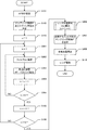
次に、図1Aを参照して、上記構成を有する撮像装置1による合焦動作(AF動作)について説明する。図1Aは、撮像装置1のAF動作手順を示すフローチャートである。この動作に関する制御プログラムは、MPU15によって実行される。撮像装置1がAF動作を開始すると、本フローチャートの処理が開始する。
Next, with reference to FIG. 1A, the focusing operation (AF operation) by the
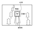
S101で、MPU15は、AF枠を設定する。例えば、MPU15は、図3に示すように、画像全領域の中で、AFを行う枠の位置と大きさを設定する。AF枠の位置と大きさは、撮影モードに応じて、任意に決められてよい。図3は、顔検知モードで人間の顔に合わせてAF枠が設定された時の概念図である。MPU15は、この時のAF枠の位置と大きさを記憶する。
In S101, the
S102で、MPU15は、S101で設定したAF枠でAFスキャン(焦点検出動作)を行うための、サンプリング間隔P(フォーカスレンズ群3のスキャン間隔)と、スキャン回数Nを決定する。
In S102, the
なお、一般的に、複数回、サンプリング間隔を変化させて合焦位置探索を行う場合は、始めにサンプリング間隔を広く設定し、おおまかな合焦位置を見つける(粗スキャン)。そして、その後に、粗スキャンで見つけた合焦位置付近を粗スキャン時よりも細かなサンプリング間隔でスキャンする(密スキャン)。 In general, when a focus position search is performed by changing the sampling interval a plurality of times, first, the sampling interval is set wide to find a rough focus position (rough scan). Thereafter, the vicinity of the in-focus position found by the coarse scan is scanned at a finer sampling interval than during the coarse scan (fine scan).
S103で、MPU15は、スキャン回数をカウントするための変数nを1に初期化する。
In S103, the
S104で、MPU15は、第2モータ駆動回路19を制御することにより、フォーカスレンズ群3をスキャン開始位置に移動させる。そして、MPU15は、スキャンAF処理回路14を用いることにより現在のスキャン位置における焦点評価値Ev[1]を算出して記憶する。
In S104, the
S105で、MPU15は、nに1を加算する。S106で、MPU15は、n>Nであるか否かを判定する。n>Nでない場合、処理はS104に戻り、MPU15は、第2モータ駆動回路19を制御することにより、フォーカスレンズ群3をサンプリング間隔Pだけ移動させ、焦点評価値Ev[n]を算出する。これにより、スキャン開始位置からスキャン終了位置までの各スキャン位置における焦点評価値Ev[n](n=1,2,3,...,N)が得られる。
In S105, the
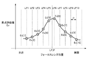
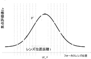
各スキャン位置に対応するフォーカスレンズ位置LP[n]と、焦点評価値Ev[n]との関係を図6に示す。図6は、フォーカスレンズ群3をフォーカスレンズ位置LP1からLP10までサンプリング間隔Pで移動させた時の、焦点評価値Ev[n]の変化を表している。焦点評価値Evは、合焦状態に近いほど大きい値をとるパラメータであり、図6では、フォーカスレンズ位置LP6が最も合焦位置に近い。この場合、内挿計算(詳細は後述)によって求められたLP6付近の位置LP_Pにフォーカスレンズ群3を駆動させることで、ピントの合った画像を取得することができる。
FIG. 6 shows the relationship between the focus lens position LP [n] corresponding to each scan position and the focus evaluation value Ev [n]. FIG. 6 shows a change in the focus evaluation value Ev [n] when the
S107で、MPU15は、焦点評価値の最大値に対応するフォーカスレンズ位置と、焦点評価値の変曲点に対応するフォーカスレンズ位置との間の距離(レンズ位置距離i)を算出する。算出処理(レンズ位置距離iは2つの位置間でのレンズの移動量に相当するため、「移動量取得処理」とも呼ぶ)の詳細については、図1Bを参照して後述する。
In S107, the
S108で、MPU15は、P’=(i×M)Pにより、サンプリング間隔P’を算出する。ここで、サンプリング間隔P’は、最終的な合焦位置であるフォーカスレンズ位置LP_Pを算出するためのサンプリング間隔である。また、Mは係数である。係数Mの大きさは、フォーカスレンズ位置LP_Pの内挿計算方法(後述)に応じて変化してもよいし、実験的に、最も合焦精度の良くなるサンプリング間隔とその時のレンズ位置距離iの大きさから求められる値でもよい。また、i×Mの値が実際のサンプリング間隔で実現不可能な時には、i×Mの四捨五入([i×M+0.5])によりP’をPの整数倍にしてもよい。或いは、フォーカスレンズ群3を再度駆動することにより、(i×M)Pにより算出されたサンプリング間隔P’で焦点評価値を取得し直してもよい。
In S108, the
直線近似による内挿計算時のサンプリング間隔と合焦精度の関係を図11に示した。図11では、図6のように焦点評価値Evが得られていた場合を想定しており、点線はノイズが無い場合のサンプリング間隔と合焦精度の関係を示し、実線はノイズがある場合のサンプリング間隔と合焦精度の関係を示す。図11のグラフにおいて、縦軸は、下に行くほど合焦精度が高い。実際の焦点評価値Evは、CCD5に乗るセンサノイズの影響を受け、関数的な変化にはならないので、実際に得られる評価値形状は、図11の実線に近い形状をとる。また、サンプリング間隔が小さい程、一点一点の焦点評価値Evのバラつきに、内挿計算結果が影響を受け易くなるので、図11の実線に示すように、サンプリング間隔が狭い場合に合焦精度が悪化する。図11において、極小値に対応するサンプリング間隔P’は、ノイズ量によって変化しない。そのため、サンプリング間隔P’で内挿計算を行うことにより、合焦精度を向上させることができる。
FIG. 11 shows the relationship between the sampling interval and the focusing accuracy at the time of interpolation calculation by linear approximation. In FIG. 11, it is assumed that the focus evaluation value Ev is obtained as shown in FIG. 6, the dotted line shows the relationship between the sampling interval and the focusing accuracy when there is no noise, and the solid line shows the case when there is noise. The relationship between sampling interval and focusing accuracy is shown. In the graph of FIG. 11, the vertical axis shows higher focusing accuracy as it goes down. Since the actual focus evaluation value Ev is affected by sensor noise on the
一般的に、直線近似による内挿計算では、最も合焦精度の良くなるサンプリング間隔は、前述したレンズ位置距離iの大きさと相関があり、そのサンプリング間隔の大きさは、レンズ位置距離iの1.4倍程度である。即ち、前述の係数Mは1.4とすることができる。図12に示すように、レンズ位置距離iから設定されたサンプリング間隔P’を用いる場合、通常、十字と三角で示した位相の他に、円で示した位相でも、算出されるフォーカスレンズ位置LP_Pが実際の合焦位置に近くなる。このように、レンズ位置距離iのM倍の大きさのサンプリング間隔P’を用いると、直線近似によって作られる3点の重心が常に合焦位置付近を捉えるので、図11に示すように合焦精度が良くなる。 In general, in the interpolation calculation by linear approximation, the sampling interval with the best focusing accuracy is correlated with the lens position distance i described above, and the size of the sampling interval is 1 of the lens position distance i. About 4 times. That is, the above-mentioned coefficient M can be set to 1.4. As shown in FIG. 12, when the sampling interval P ′ set from the lens position distance i is used, the calculated focus lens position LP_P is usually calculated using a phase indicated by a circle in addition to a phase indicated by a cross and a triangle. Becomes close to the actual in-focus position. As described above, when a sampling interval P ′ having a size M times the lens position distance i is used, the center of gravity of the three points created by the linear approximation always captures the vicinity of the in-focus position. Accuracy is improved.
図1Aに戻り、S109で、MPU15は、S108で算出されたサンプリング間隔P’で内挿計算を行い、フォーカスレンズ位置LP_Pを求める。直線近似による内挿計算の方法の一例を、図7を参照しながら説明する。直線近似による方法は、高次近似による合焦点検出方法よりも演算負荷が少ない。また、直線近似による方法は、合焦位置付近の焦点評価値形状にバラつきが多い場合でも、焦点評価値の最大値付近のレンズ位置を検出できるため、ノイズに強いという利点がある。
Returning to FIG. 1A, in S109, the
図7は、図6の合焦位置付近を拡大した図である。この時、フォーカスレンズ位置LP_Pを求める方法は種々あるが、本実施形態は、直線近似によるフォーカスレンズ位置LP_Pの算出方法に関するものである。以下、直線近似により得られるフォーカスレンズ位置LP_Pを、合焦位置LP_P又は補間合焦位置LP_Pと呼ぶ場合もある。 FIG. 7 is an enlarged view of the vicinity of the in-focus position in FIG. At this time, there are various methods for obtaining the focus lens position LP_P, but this embodiment relates to a method for calculating the focus lens position LP_P by linear approximation. Hereinafter, the focus lens position LP_P obtained by linear approximation may be referred to as a focus position LP_P or an interpolation focus position LP_P.
直線近似によって、補間合焦位置LP_Pを求める一例について説明する。補間合焦位置LP_Pを求める際には、まず、MPU15は、焦点評価値の最大値(図7ではEv[6])、2番目に大きい値(Ev[5])、3番目に大きい値(Ev[7])と、そのレンズ位置LP6、LP5、L7を検出する。この時、まず、Ev[6]とEv[7]を通る直線L1の式を求める。L1は、横軸をx、縦軸をyとすると、L1は、
L1:y=((Ev[7]−Ev[6])/(LP7−LP6))×x+((LP7×Ev[6]−LP6×Ev[7])/(LP7−LP6))
で求めることができる。
An example of obtaining the interpolation focus position LP_P by linear approximation will be described. When obtaining the interpolation focus position LP_P, first, the
L1: y = ((Ev [7] −Ev [6]) / (LP7−LP6)) × x + ((LP7 × Ev [6] −LP6 × Ev [7]) / (LP7−LP6))
Can be obtained.
次に、L1と傾きの符合が逆で、Ev[5]を通る直線L2の式を求める。同様に、横軸をx、縦軸をyとすると、L2は、
L2:y=−((Ev[7]−Ev[6])/(LP7−LP6))×x+Ev[5]+((Ev[7]−Ev[6])/(LP7−LP6))×LP5
で求めることができる。
Next, an equation of a straight line L2 passing through Ev [5] with the sign of the slope of L1 being opposite is obtained. Similarly, if the horizontal axis is x and the vertical axis is y, L2 is
L2: y = − ((Ev [7] −Ev [6]) / (LP7−LP6)) × x + Ev [5] + ((Ev [7] −Ev [6]) / (LP7−LP6)) × LP5
Can be obtained.
この時の、L1とL2の交点のx座標が補間合焦位置LP_Pとなる。つまり、
LP_P=(Ev[5]+((Ev[7]−Ev[6])/(LP7−LP6))×LP5−((LP7×Ev[6]−LP6×Ev[7])/(LP7−LP6)))/(2×((Ev[7]−Ev[6])/(LP7−LP6)))
となる。ここでは、3点から直線近似を行う方法を示したが、4点から行ってもよい。或いは、図8に示すように、最大値から三番目に大きい値までが一列に並んでいる場合には、最大値Ev[6]をとるレンズ位置LP6の位置をLP_Pとするような、場合分けを行ってもよい。
At this time, the x coordinate of the intersection of L1 and L2 becomes the interpolation focus position LP_P. That means
LP_P = (Ev [5] + ((Ev [7] −Ev [6]) / (LP7−LP6)) × LP5 − ((LP7 × Ev [6] −LP6 × Ev [7]) / (LP7− LP6))) / (2 × ((Ev [7] -Ev [6]) / (LP7-LP6)))
It becomes. Here, a method of performing linear approximation from three points is shown, but it may be performed from four points. Alternatively, as shown in FIG. 8, when the maximum value to the third largest value are arranged in a line, the lens position LP6 taking the maximum value Ev [6] is set to LP_P. May be performed.
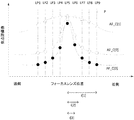
図4は、焦点評価値Ev[n]を取得した際のサンプリング間隔Pよりも、内挿計算を行う際のサンプリング間隔P’が大きい場合の処理の概念図である。この例では、各フォーカスレンズ位置LP[n]での焦点評価値Ev[n]が取得されている。従来では、各レンズ位置LP5、LP6、LP7とその評価値Ev[5]、Ev[6]、Ev[7]を使用して、図7のように内挿計算が行われていた。それに対し、本実施形態では、レンズ位置距離iの定数倍(もしくは、それに一番近い整数)であるサンプリング間隔P’で内挿計算を行うことにより、LP_Pを求める。図4では、各レンズ位置LP1、LP5、LP9とその評価値Ev[1]、Ev[5]、Ev[9]を用いる。この時、位相違いの各レンズ位置LP2、LP6、LP10とその評価値Ev[2]、Ev[6]、Ev[10]を用いてもよい。或いは、位相違いで算出された複数のLP_Pの平均値を最終的なLP_Pとしてもよい。なお、位相が異なるということは、サンプリング間隔P’でのサンプリング(評価値取得)の開始位置が異なるということである。 FIG. 4 is a conceptual diagram of processing when the sampling interval P ′ when performing the interpolation calculation is larger than the sampling interval P when the focus evaluation value Ev [n] is acquired. In this example, the focus evaluation value Ev [n] at each focus lens position LP [n] is acquired. Conventionally, interpolation calculation is performed as shown in FIG. 7 using the lens positions LP5, LP6, LP7 and their evaluation values Ev [5], Ev [6], Ev [7]. On the other hand, in this embodiment, LP_P is obtained by performing interpolation calculation at a sampling interval P ′ that is a constant multiple of the lens position distance i (or an integer closest thereto). In FIG. 4, the lens positions LP1, LP5, LP9 and their evaluation values Ev [1], Ev [5], Ev [9] are used. At this time, the lens positions LP2, LP6, LP10 having different phases and the evaluation values Ev [2], Ev [6], Ev [10] may be used. Or it is good also considering the average value of several LP_P calculated by phase difference as final LP_P. Note that the difference in phase means that the start positions of sampling (acquisition of evaluation values) at the sampling interval P ′ are different.
位相違いの内挿計算結果の平均値を用いることで、より合焦精度が向上する理由を、図13を用いて説明する。一般に、最初に焦点評価値を取得する際のサンプリング間隔をP、内挿計算により合焦位置を算出する際のサンプリング間隔をP’とすると、n=P’/P通りの位相で合焦位置LP_P’を算出することができる。この時の、サンプリング位相nと、LP_P’の関係を、図13に示した。縦軸が0の位置が実際の合焦位置を示しているので、複数位相での内挿計算結果を平均すると、より実際の合焦位置に近づく可能性を高めることができる。 The reason why the focusing accuracy is further improved by using the average value of the interpolation calculation result of the phase difference will be described with reference to FIG. In general, assuming that the sampling interval when acquiring the focus evaluation value for the first time is P and the sampling interval when calculating the focus position by interpolation calculation is P ′, the focus position is n = P ′ / P phases. LP_P ′ can be calculated. The relationship between the sampling phase n and LP_P ′ at this time is shown in FIG. Since the position where the vertical axis is 0 indicates the actual in-focus position, the average of interpolation calculation results in a plurality of phases can increase the possibility of approaching the actual in-focus position.
図1Aに戻り、S110で、MPU15は、第2モータ駆動回路19を制御することにより、S109で求めた合焦位置LP_Pへフォーカスレンズ群3を移動させる。これにより、一連のAF動作が終了する。
Returning to FIG. 1A, in S110, the
次に、図1B及び図5を参照して、レンズ位置距離iの算出方法について詳細に説明する。S151で、MPU15は、dx[1]=Ev[2]−Ev[1]により、焦点評価値Ev[1]の微分値dx[1]を計算する。
Next, a method for calculating the lens position distance i will be described in detail with reference to FIGS. 1B and 5. In S151, the
S152で、MPU15は、微分値の最大値Max_dx及び最小値0_dxを共に|dx[1]|に初期化する。また、MPU15は、Max_dx及び0_dxに対応するフォーカスレンズ位置を示す変数Max_xdx及び0_xdxを1に初期化する。S153で、MPU15は、変数nを2に初期化する。
In S152, the
S153からS160で、MPU15は、dx[n]=Ev[n+1]−Ev[n]により、dx[2]からdx[N−1]を計算する。ここで、Nは図1AのS102で決定した値であり、本実施形態では10である。また、MPU15は、Max_dx及び0_dxを随時更新する(S155及びS157の条件分岐参照)。
In S153 to S160, the
図5の上側は、図1AのS104で算出されたEv[1]からEv[10]を示し、図5の下側は、図1BのS151及びS154で算出されたdx[1]からdx[9]を示す。図5の下側に示すようなdx[1]からdx[9]が得られた場合、最終的に、Max_dx=|dx[3]|、0_dx=|dx[6]|となる。また、図1BのS156及びS158に示すように、MPU15は、Max_dx及び0_dxを更新する際に、Max_xdx及び0_xdxもその時点のnで更新する。従って、最終的には、Max_xdx=3、0_xdx=6となる。
The upper side of FIG. 5 shows Ev [1] to Ev [10] calculated in S104 of FIG. 1A, and the lower side of FIG. 5 shows dx [1] to dx [1] calculated in S151 and S154 of FIG. 9]. When dx [9] is obtained from dx [1] as shown in the lower part of FIG. 5, Max_dx = | dx [3] | and 0_dx = | dx [6] | are finally obtained. As shown in S156 and S158 of FIG. 1B, when the
S161で、MPU15は、i=|Max_xdx−0_xdx|により、焦点評価値の最大値に対応するフォーカスレンズ位置と、焦点評価値の変曲点に対応するフォーカスレンズ位置との間の距離である、レンズ位置距離iを算出する。図5の例では、i=3が得られる。
In S161, the
なお、上の説明では、Max_xdx及び0_xdxは、Max_dx及び0_dxの更新時のnの値であるものとした。しかしながら、MPU15は、Max_xdx及び0_xdxを、焦点評価値の最大値又は変曲点を含む複数の点に基づく線形補間等によって求めてもよい。例えば、図5の例では、焦点評価値の真の最大値は、n=6の位置ではなく、n=6とn=7の間の位置にあると考えられる。そこで、MPU15は、dx[5]、dx[6]、及びdx[7]と、これらに対応するn=5,6,7とに基づき、高次近似や線形補間などにより0_xdxの値を求めることができる。この場合、レンズ位置距離iは、整数ではなく小数の値になる可能性がある。
In the above description, it is assumed that Max_xdx and 0_xdx are the values of n when Max_dx and 0_dx are updated. However, the
また、上の説明では、微分値を用いて焦点評価値の変曲点を算出する方法を挙げたが、二次微分の極小値を用いてもよい。また、評価値の裾野(合焦位置から遠い)部分では、微分値が小さい値をとるので、焦点評価値の変化量が一定以下と続く場合には、変曲点の演算から除外するなどしてもよい。 In the above description, the method of calculating the inflection point of the focus evaluation value using the differential value has been described. However, the minimum value of the secondary differential may be used. Also, at the base of the evaluation value (far from the in-focus position), the differential value takes a small value, so if the amount of change in the focus evaluation value continues below a certain value, it is excluded from the inflection point calculation. May be.
以上説明したように、第1の実施形態によれば、撮像装置1は、サンプリング間隔P及びスキャン回数Nにより、N個の焦点評価値Ev[n]を取得する。そして、撮像装置1は、焦点評価値の最大値に対応するフォーカスレンズ位置と、焦点評価値の変曲点に対応するフォーカスレンズ位置との間の距離である、レンズ位置距離iを算出する。そして、撮像装置1は、レンズ位置距離i及び係数Mに基づいてサンプリング間隔P’を算出し、サンプリング間隔P’に基づく補間演算により最終的な合焦位置を算出する。
As described above, according to the first embodiment, the
レンズ位置距離iは、焦点評価値の形状(急峻性)を示す指標であり、フォーカスレンズ群3の移動量(2つの位置間の距離)に相当する。このような性質を持つレンズ位置距離iに基づいてサンプリング間隔P’を決定することにより、合焦位置の補間演算の精度が向上する。従って、本実施形態によれば、焦点調節制御の精度を向上させることが可能となる。 The lens position distance i is an index indicating the shape (steepness) of the focus evaluation value, and corresponds to the amount of movement of the focus lens group 3 (distance between two positions). By determining the sampling interval P ′ based on the lens position distance i having such properties, the accuracy of the in-focus position interpolation calculation is improved. Therefore, according to the present embodiment, it is possible to improve the accuracy of the focus adjustment control.
なお、上記の説明では、焦点評価値の形状(急峻性)を示す指標として、焦点評価値の最大値に対応するフォーカスレンズ位置と、焦点評価値の変曲点に対応するフォーカスレンズ位置との間の距離である、レンズ位置距離iを用いた。しかしながら、代わりに、例えば焦点評価値の半値幅に対応するレンズ位置距離を指標として用いてもよい。合焦位置の補間演算の精度が向上するようなサンプリング間隔P’を決定する際に利用可能な指標であれば、いかなる指標を用いても構わない。 In the above description, as an index indicating the shape (steepness) of the focus evaluation value, the focus lens position corresponding to the maximum value of the focus evaluation value and the focus lens position corresponding to the inflection point of the focus evaluation value. The lens position distance i, which is the distance between them, was used. However, instead, for example, the lens position distance corresponding to the half-value width of the focus evaluation value may be used as an index. Any index may be used as long as it is an index that can be used when determining the sampling interval P ′ that improves the accuracy of the interpolation calculation of the in-focus position.
[第2の実施形態]
以下、図9及び図10を参照して、第2の実施形態にについて説明する。第2の実施形態では、複数帯域での焦点評価値の計算が行われる。本実施形態において、撮像装置1の基本的な構成は、第1の実施形態と同様である(図2参照)。
[Second Embodiment]
Hereinafter, the second embodiment will be described with reference to FIGS. 9 and 10. In the second embodiment, calculation of focus evaluation values in a plurality of bands is performed. In the present embodiment, the basic configuration of the
図9を参照して、撮像装置1による合焦動作(AF動作)について説明する。図9は、撮像装置1のAF動作手順を示すフローチャートである。図9において、図1Aと同一又は同様の処理が行われるステップには図1Aと同一の符号を付し、説明を省略する。
With reference to FIG. 9, the focusing operation (AF operation) by the
S901で、MPU15は、フィルタの番号を示す変数kを1に初期化する。撮像装置1は、通過帯域が異なるK個のフィルタを有し、焦点評価値の計算は、これらのフィルタのうちのいずれかによって処理された信号に基づいて行われる。本実施形態では、K=3とする。
In step S901, the
S902で、MPU15は、k番目のフィルタ(フィルタ[k])を選択する。S903で、MPU15は、スキャンAF処理回路14を用いることにより、焦点評価値AF_C[k][n]を算出する。ここでの処理は、図1AのS104と概ね同じであるが、フィルタ[k]により処理された信号に基づいて演算が行われる点がS104と異なる。
In S902, the
S904で、MPU15は、kに1を加算する。S905で、MPU15は、k>Kであるか否かを判定する。k>Kでない場合、処理はS902に戻り、MPU15は、他のフィルタを選択して、同様の処理を繰り返す。
In S904, the
S901からS905、S105、及びS106の処理により、図10に示すような焦点評価値が取得される。一般的に、低帯域のフィルタ処理を行うと、AF_C[1]のように、焦点評価値の変化量が少なく、広いフォーカスレンズ位置で焦点評価値の変化を検出することができるなだらかな評価値形状が得られる。逆に、高帯域のフィルタ処理を行うと、AF_C[3]のように、合焦位置付近で、焦点評価値の変化量が大きくなり、急峻な評価値形状が得られる。 A focus evaluation value as shown in FIG. 10 is acquired by the processing from S901 to S905, S105, and S106. In general, when low-band filter processing is performed, a gentle evaluation value that can detect a change in the focus evaluation value at a wide focus lens position with a small amount of change in the focus evaluation value as in AF_C [1]. A shape is obtained. Conversely, when high-band filter processing is performed, as in AF_C [3], the amount of change in the focus evaluation value increases near the in-focus position, and a steep evaluation value shape is obtained.
S906で、MPU15は、レンズ位置距離i[k](k=1〜K)を算出する。ここでの処理は、図1AのS107と概ね同じであるが、K個のフィルタそれぞれについて、対応する焦点評価値AF_C[k][n](n=1〜N)に基づいてレンズ位置距離が算出される。図10に示すように、高帯域で計算された評価値ほど形状が急峻になるので、レンズ位置距離i[k]は小さい値をとる。なお、第1の実施形態で説明した通り、線形補間などを行う場合はレンズ位置距離i[k]は小数になる場合もあり、図10においては、i[2]は小数である。
In S906, the
S907で、MPU15は、S906で算出されたレンズ位置距離i[k]に基づき、合焦位置の算出時に使用するフィルタ及びサンプリング間隔P’を決定する。この選択について、図10を用いて説明する。図10のように、サンプリング間隔Pで、3種類のフィルタ帯域での焦点評価値がそれぞれ得られたとする。この時、i[1]、i[2]、i[3]は、それぞれ図10の下に示す値になる。この時、第1の実施形態で述べたように、合焦位置計算に用いるサンプリング間隔P’は、
P’=(i[k]×M)P (M=定数)
であり、i[k]×Mは整数である方がよい。図10の例では、M=1.4の場合、k=2の時に、i[k]×M=2(即ち、P’=2P)となる。そこで、MPU15は、フィルタ[2]を選択し、サンプリング間隔P’=2Pとする。より一般的に言えば、MPU15は、各フィルタに対応するP’のうち、Pの整数倍に最も近いものを最終的なP’として決定する。但し、Pの整数倍に最も近いものがPの完全な整数倍でない場合は、MPU15は、Pの整数倍に最も近く、且つPの完全な整数倍であるものを、最終的なP’として決定する。
In S907, the
P ′ = (i [k] × M) P (M = constant)
I [k] × M should be an integer. In the example of FIG. 10, when M = 1.4, when k = 2, i [k] × M = 2 (ie, P ′ = 2P). Therefore, the
S908で、MPU15は、S907で選択されたフィルタに対応して取得された焦点評価値を、S907で決定されたサンプリング間隔P’で内挿計算を行い、フォーカスレンズ位置LP_Pを求める。ここでの具体的な計算方法は、図1AのS109と同様である。
In S908, the
このように、MPU15は、定数Mとレンズ位置距離i[k]の乗算の値が最も整数値に近くなるという条件に基づき、フィルタと、サンプリング間隔P’とを決定する。条件を満たすフィルタが複数存在する場合は、MPU15は、P’が最も小さくなるフィルタを選択してもよい。或いは、MPU15は、これら複数のフィルタそれぞれを用いてS908で合省位置の算出を行い、その平均値を最終的な合焦位置としてもよい。また、P’が2以上の場合には、第1の実施形態で述べたように、MPU15は、S908での合焦位置算出の際に、複数の位相で計算を行い、その平均値を最終的な合焦位置としてもよい。
As described above, the
以上説明したように、第2の実施形態によれば、撮像装置1は、複数帯域で焦点評価値の計算を行い、合焦精度を最も向上させる帯域のフィルタを選択する。これにより、焦点調節制御の精度を向上させることが可能となる。
As described above, according to the second embodiment, the
[その他の実施形態]
上記の実施形態では、被写体の合焦状態の変化を、フォーカスレンズ群3の移動により実現した。しかしながら、合焦状態の変化を実現する方法については、これに限らない。例えば、フォーカスレンズ群3ではなくCCD5を移動させることにより合焦状態の変化を実現してもよい。この場合、CCD5が焦点調節部材としての役割を果たす。また、光線の入射角度情報(ライトフィールド情報)を取得できる撮像装置であれば、再構成処理により合焦状態の変化を実現してもよい。
[Other Embodiments]
In the above embodiment, the change of the focus state of the subject is realized by the movement of the
また、本発明は、以下の処理を実行することによっても実現される。即ち、上述した実施形態の機能を実現するソフトウェア(プログラム)を、ネットワーク又は各種記憶媒体を介してシステム或いは装置に供給し、そのシステム或いは装置のコンピュータ(又はCPUやMPU等)がプログラムを読み出して実行する処理である。 The present invention can also be realized by executing the following processing. That is, software (program) that realizes the functions of the above-described embodiments is supplied to a system or apparatus via a network or various storage media, and a computer (or CPU, MPU, etc.) of the system or apparatus reads the program. It is a process to be executed.
Claims (10)
撮像素子の出力信号に基づいて焦点評価値を取得する評価値取得手段と、
前記焦点調節手段に前記焦点調節部材の位置を第1のサンプリング間隔で移動させ、前記評価値取得手段に各位置に対応する焦点評価値を取得させる制御手段と、
前記各位置に対応する焦点評価値に基づき、前記評価値取得手段により取得される焦点評価値の最大値からの変化の急峻性の指標となる、前記焦点調節部材の位置の移動量を取得する移動量取得手段と、
前記移動量に基づいて第2のサンプリング間隔を決定する決定手段と、
前記焦点調節部材の前記第2のサンプリング間隔での各位置に対応する焦点評価値に基づいて、合焦位置を検出する検出手段と、
を備えることを特徴とする焦点調節装置。 Focus adjusting means for adjusting the focus by moving the position of the focus adjusting member;
Evaluation value acquisition means for acquiring a focus evaluation value based on an output signal of the image sensor;
Control means for causing the focus adjustment means to move the position of the focus adjustment member at a first sampling interval, and for causing the evaluation value acquisition means to acquire a focus evaluation value corresponding to each position;
Based on the focus evaluation value corresponding to each position, the amount of movement of the position of the focus adjustment member, which is an indicator of the steepness of change from the maximum value of the focus evaluation value acquired by the evaluation value acquisition means, is acquired Movement amount acquisition means;
Determining means for determining a second sampling interval based on the amount of movement;
Detection means for detecting a focus position based on a focus evaluation value corresponding to each position at the second sampling interval of the focus adjustment member;
A focus adjusting apparatus comprising:
ことを特徴とする請求項1に記載の焦点調節装置。 The detection means moves the position of the focus adjustment member at the second sampling interval in the focus adjustment means, and causes the evaluation value acquisition means to acquire a focus evaluation value corresponding to each position, thereby adjusting the focus adjustment. The focus adjustment apparatus according to claim 1, wherein a focus evaluation value corresponding to each position of the member at the second sampling interval is acquired.
前記検出手段は、前記焦点調節部材の前記第1のサンプリング間隔での各位置に対応する焦点評価値から、前記焦点調節部材の前記第2のサンプリング間隔での各位置に対応する焦点評価値を取得する
ことを特徴とする請求項1に記載の焦点調節装置。 The determining means determines the second sampling interval so that the second sampling interval is an integral multiple of the first sampling interval;
The detection means obtains a focus evaluation value corresponding to each position of the focus adjustment member at the second sampling interval from a focus evaluation value corresponding to each position of the focus adjustment member at the first sampling interval. The focus adjustment apparatus according to claim 1, wherein the focus adjustment apparatus is obtained.
前記決定手段は、
前記複数の帯域それぞれが選択された状態で前記評価値取得手段により取得された焦点評価値に基づいて前記移動量取得手段により取得された各移動量について、第2のサンプリング間隔を決定し、
前記複数の帯域それぞれに対応する第2のサンプリング間隔のうち、前記第1のサンプリング間隔の整数倍に最も近いものを選択し、前記第1のサンプリング間隔の整数倍であって当該選択した第2のサンプリング間隔に最も近い値を、最終的な前記第2のサンプリング間隔として決定し、
前記検出手段は、前記最終的な第2のサンプリング間隔に対応する帯域が選択された状態で前記評価値取得手段により取得された焦点評価値に基づいて、前記合焦位置を検出する
ことを特徴とする請求項1に記載の焦点調節装置。 Filter means for selecting one of a plurality of bands and passing the selected band of the output signal of the image sensor;
The determining means includes
A second sampling interval is determined for each movement amount acquired by the movement amount acquisition unit based on the focus evaluation value acquired by the evaluation value acquisition unit in a state where each of the plurality of bands is selected,
The second sampling interval corresponding to each of the plurality of bands is selected to be the closest to an integer multiple of the first sampling interval, and is an integer multiple of the first sampling interval and the selected second A value closest to the sampling interval is determined as the final second sampling interval,
The detection means detects the in-focus position based on a focus evaluation value acquired by the evaluation value acquisition means in a state where a band corresponding to the final second sampling interval is selected. The focus adjusting apparatus according to claim 1.
異なる複数の位置を開始位置として、各開始位置について前記焦点調節部材の前記第2のサンプリング間隔での各位置に対応する焦点評価値を取得し、
前記各開始位置について、前記焦点調節部材の前記第2のサンプリング間隔での各位置に対応する焦点評価値に基づいて、合焦位置を検出し、
前記各開始位置に対応する合焦位置の平均値を最終的な前記合焦位置として検出する
ことを特徴とする請求項1乃至4のいずれか1項に記載の焦点調節装置。 The detection means includes
Using a plurality of different positions as start positions, a focus evaluation value corresponding to each position at the second sampling interval of the focus adjustment member is obtained for each start position,
For each start position, a focus position is detected based on a focus evaluation value corresponding to each position at the second sampling interval of the focus adjustment member;
The focus adjustment apparatus according to any one of claims 1 to 4, wherein an average value of focus positions corresponding to the start positions is detected as the final focus position.
ことを特徴とする請求項1乃至5のいずれか1項に記載の焦点調節装置。 The movement amount acquisition means includes the position of the focus adjustment member corresponding to the maximum value of the focus evaluation value acquired by the evaluation value acquisition means and the focus adjustment member corresponding to the inflection point of the change of the focus evaluation value. The focus adjustment apparatus according to claim 1, wherein a distance from the position of the focus position is acquired as the amount of movement.
ことを特徴とする請求項1乃至6のいずれか1項に記載の焦点調節装置。 The movement amount acquisition unit acquires, as the movement amount, a distance between positions of the focus adjustment member corresponding to a half-value width of the focus evaluation value acquired by the evaluation value acquisition unit. The focus adjustment apparatus according to any one of 1 to 6.
前記撮像素子と、
を備えることを特徴とする撮像装置。 The focus adjustment device according to any one of claims 1 to 7,
The imaging element;
An imaging apparatus comprising:
前記焦点調節装置の焦点調節手段が、焦点調節部材の位置を移動させることにより焦点調節を行う焦点調節工程と、
前記焦点調節装置の評価値取得手段が、撮像素子の出力信号に基づいて焦点評価値を取得する評価値取得工程と、
前記焦点調節装置の制御手段が、前記焦点調節工程により前記焦点調節部材の位置を第1のサンプリング間隔で移動させ、前記評価値取得工程により各位置に対応する焦点評価値を取得する制御工程と、
前記焦点調節装置の移動量取得手段が、前記各位置に対応する焦点評価値に基づき、前記評価値取得工程により取得される焦点評価値の最大値からの変化の急峻性の指標となる、前記焦点調節部材の位置の移動量を取得する移動量取得工程と、
前記焦点調節装置の決定手段が、前記移動量に基づいて第2のサンプリング間隔を決定する決定工程と、
前記焦点調節装置の検出手段が、前記焦点調節部材の前記第2のサンプリング間隔での各位置に対応する焦点評価値に基づいて、合焦位置を検出する検出工程と、
を備えることを特徴とする焦点調節方法。 A focus adjustment method using a focus adjustment device,
A focus adjusting step in which the focus adjusting means of the focus adjusting device adjusts the focus by moving the position of the focus adjusting member;
An evaluation value acquisition unit for acquiring an evaluation value based on an output signal of the image sensor, wherein the evaluation value acquisition unit of the focus adjustment device,
A control step in which the control means of the focus adjustment apparatus moves the position of the focus adjustment member at a first sampling interval by the focus adjustment step, and acquires a focus evaluation value corresponding to each position by the evaluation value acquisition step; ,
The movement amount acquisition means of the focus adjustment device is an index of steepness of change from the maximum value of the focus evaluation value acquired by the evaluation value acquisition step based on the focus evaluation value corresponding to each position. A movement amount acquisition step of acquiring a movement amount of the position of the focus adjustment member;
A determination step in which a determination unit of the focus adjustment apparatus determines a second sampling interval based on the movement amount;
A detecting step in which the detection means of the focus adjustment device detects a focus position based on a focus evaluation value corresponding to each position of the focus adjustment member at the second sampling interval;
A focus adjustment method comprising:
Priority Applications (1)
| Application Number | Priority Date | Filing Date | Title |
|---|---|---|---|
| JP2013234312A JP6224995B2 (en) | 2013-11-12 | 2013-11-12 | FOCUS ADJUSTMENT DEVICE, IMAGING DEVICE, FOCUS ADJUSTMENT METHOD, AND PROGRAM |
Applications Claiming Priority (1)
| Application Number | Priority Date | Filing Date | Title |
|---|---|---|---|
| JP2013234312A JP6224995B2 (en) | 2013-11-12 | 2013-11-12 | FOCUS ADJUSTMENT DEVICE, IMAGING DEVICE, FOCUS ADJUSTMENT METHOD, AND PROGRAM |
Publications (2)
| Publication Number | Publication Date |
|---|---|
| JP2015094859A JP2015094859A (en) | 2015-05-18 |
| JP6224995B2 true JP6224995B2 (en) | 2017-11-01 |
Family
ID=53197292
Family Applications (1)
| Application Number | Title | Priority Date | Filing Date |
|---|---|---|---|
| JP2013234312A Expired - Fee Related JP6224995B2 (en) | 2013-11-12 | 2013-11-12 | FOCUS ADJUSTMENT DEVICE, IMAGING DEVICE, FOCUS ADJUSTMENT METHOD, AND PROGRAM |
Country Status (1)
| Country | Link |
|---|---|
| JP (1) | JP6224995B2 (en) |
Family Cites Families (7)
| Publication number | Priority date | Publication date | Assignee | Title |
|---|---|---|---|---|
| JP3103587B2 (en) * | 1990-04-25 | 2000-10-30 | オリンパス光学工業株式会社 | Automatic focusing device |
| JP3547777B2 (en) * | 1993-11-19 | 2004-07-28 | 富士写真フイルム株式会社 | Auto focus device |
| JP2009048136A (en) * | 2007-08-23 | 2009-03-05 | Fujifilm Corp | Focusing device and focusing method |
| JP5106143B2 (en) * | 2008-01-21 | 2012-12-26 | キヤノン株式会社 | Automatic focus adjustment device and automatic focus adjustment method thereof |
| JP5417899B2 (en) * | 2009-02-27 | 2014-02-19 | 株式会社ニコン | Focus detection apparatus and imaging apparatus |
| KR101085925B1 (en) * | 2010-03-23 | 2011-11-23 | 삼성전자주식회사 | Image pickup apparatus to perform auto focusing function by using plurality of band pass filters and auto focusing method applied the same |
| JP5762156B2 (en) * | 2011-06-08 | 2015-08-12 | キヤノン株式会社 | IMAGING DEVICE, FOCUS ADJUSTMENT METHOD, AND PROGRAM |
-
2013
- 2013-11-12 JP JP2013234312A patent/JP6224995B2/en not_active Expired - Fee Related
Also Published As
| Publication number | Publication date |
|---|---|
| JP2015094859A (en) | 2015-05-18 |
Similar Documents
| Publication | Publication Date | Title |
|---|---|---|
| JP5609270B2 (en) | IMAGING DEVICE, IMAGING SYSTEM, IMAGING DEVICE CONTROL METHOD, AND PROGRAM | |
| JP5621325B2 (en) | FOCUS CONTROL DEVICE, FOCUS CONTROL METHOD, LENS DEVICE, FOCUS LENS DRIVING METHOD, AND PROGRAM | |
| JP2011248159A (en) | Imaging apparatus, imaging system, imaging apparatus control method and program | |
| JP2006301378A (en) | Imaging apparatus | |
| JP6116277B2 (en) | Imaging apparatus and control method thereof | |
| WO2018096816A1 (en) | Focus adjustment device, control method for focus adjustment device, and storage medium on which focus adjustment program is recorded | |
| JP4700993B2 (en) | Imaging device | |
| JP2013218297A (en) | Focus adjustment device and focus adjustment method | |
| JP5769773B2 (en) | Camera system and focus detection pixel correction method | |
| JP5106143B2 (en) | Automatic focus adjustment device and automatic focus adjustment method thereof | |
| JP6478534B2 (en) | Focus control device, imaging device, interchangeable lens, focus control method, and focus control program | |
| JP2011191617A (en) | Imaging device | |
| JP6220144B2 (en) | Focus adjustment apparatus and control method thereof | |
| JP6224995B2 (en) | FOCUS ADJUSTMENT DEVICE, IMAGING DEVICE, FOCUS ADJUSTMENT METHOD, AND PROGRAM | |
| JP2014102290A (en) | Automatic focusing apparatus | |
| US11399130B2 (en) | Focus adjustment device and focus adjustment method | |
| JP7039326B2 (en) | Focus adjustment device and control method of focus adjustment device | |
| JP2018101110A (en) | Focus detection device | |
| JP2019008005A (en) | Control device, imaging apparatus, control method, program, and storage medium | |
| US9832364B2 (en) | Automatic focal adjustment apparatus and method of controlling automatic focal adjustment apparatus, and image capture apparatus | |
| JP6351310B2 (en) | Imaging apparatus, control method therefor, program, and storage medium | |
| JP2010078681A (en) | Automatic focus adjustment device and method, and program | |
| JP2009198975A (en) | Focus adjustment device and focus adjustment method therefor | |
| JP5106146B2 (en) | Automatic focus adjustment device | |
| JP6366374B2 (en) | Focus detection apparatus and control method thereof |
Legal Events
| Date | Code | Title | Description |
|---|---|---|---|
| A621 | Written request for application examination |
Free format text: JAPANESE INTERMEDIATE CODE: A621 Effective date: 20161109 |
|
| A977 | Report on retrieval |
Free format text: JAPANESE INTERMEDIATE CODE: A971007 Effective date: 20170731 |
|
| TRDD | Decision of grant or rejection written | ||
| A01 | Written decision to grant a patent or to grant a registration (utility model) |
Free format text: JAPANESE INTERMEDIATE CODE: A01 Effective date: 20170908 |
|
| A61 | First payment of annual fees (during grant procedure) |
Free format text: JAPANESE INTERMEDIATE CODE: A61 Effective date: 20171006 |
|
| R151 | Written notification of patent or utility model registration |
Ref document number: 6224995 Country of ref document: JP Free format text: JAPANESE INTERMEDIATE CODE: R151 |
|
| LAPS | Cancellation because of no payment of annual fees |