JP6223107B2 - Image processing apparatus, image processing method, and program - Google Patents
Image processing apparatus, image processing method, and program Download PDFInfo
- Publication number
- JP6223107B2 JP6223107B2 JP2013210404A JP2013210404A JP6223107B2 JP 6223107 B2 JP6223107 B2 JP 6223107B2 JP 2013210404 A JP2013210404 A JP 2013210404A JP 2013210404 A JP2013210404 A JP 2013210404A JP 6223107 B2 JP6223107 B2 JP 6223107B2
- Authority
- JP
- Japan
- Prior art keywords
- density
- adjustment
- input
- point
- image processing
- Prior art date
- Legal status (The legal status is an assumption and is not a legal conclusion. Google has not performed a legal analysis and makes no representation as to the accuracy of the status listed.)
- Active
Links
- 238000012545 processing Methods 0.000 title claims description 110
- 238000003672 processing method Methods 0.000 title claims description 5
- 238000000034 method Methods 0.000 claims description 30
- 238000010586 diagram Methods 0.000 description 11
- 230000006870 function Effects 0.000 description 8
- 238000006243 chemical reaction Methods 0.000 description 6
- 238000002360 preparation method Methods 0.000 description 4
- 238000003705 background correction Methods 0.000 description 3
- 239000003086 colorant Substances 0.000 description 3
- 238000012423 maintenance Methods 0.000 description 3
- 238000013459 approach Methods 0.000 description 2
- 230000000694 effects Effects 0.000 description 2
- 238000007796 conventional method Methods 0.000 description 1
- 238000012937 correction Methods 0.000 description 1
- 238000013500 data storage Methods 0.000 description 1
- 238000001514 detection method Methods 0.000 description 1
- 239000004973 liquid crystal related substance Substances 0.000 description 1
- 239000011159 matrix material Substances 0.000 description 1
- 230000002093 peripheral effect Effects 0.000 description 1
- 230000001629 suppression Effects 0.000 description 1
Images


Classifications
-
- H—ELECTRICITY
- H04—ELECTRIC COMMUNICATION TECHNIQUE
- H04N—PICTORIAL COMMUNICATION, e.g. TELEVISION
- H04N1/00—Scanning, transmission or reproduction of documents or the like, e.g. facsimile transmission; Details thereof
- H04N1/46—Colour picture communication systems
- H04N1/56—Processing of colour picture signals
- H04N1/60—Colour correction or control
- H04N1/6027—Correction or control of colour gradation or colour contrast
-
- H—ELECTRICITY
- H04—ELECTRIC COMMUNICATION TECHNIQUE
- H04N—PICTORIAL COMMUNICATION, e.g. TELEVISION
- H04N1/00—Scanning, transmission or reproduction of documents or the like, e.g. facsimile transmission; Details thereof
- H04N1/40—Picture signal circuits
- H04N1/407—Control or modification of tonal gradation or of extreme levels, e.g. background level
-
- H—ELECTRICITY
- H04—ELECTRIC COMMUNICATION TECHNIQUE
- H04N—PICTORIAL COMMUNICATION, e.g. TELEVISION
- H04N1/00—Scanning, transmission or reproduction of documents or the like, e.g. facsimile transmission; Details thereof
- H04N1/46—Colour picture communication systems
- H04N1/56—Processing of colour picture signals
- H04N1/60—Colour correction or control
- H04N1/6058—Reduction of colour to a range of reproducible colours, e.g. to ink- reproducible colour gamut
- H04N1/6063—Reduction of colour to a range of reproducible colours, e.g. to ink- reproducible colour gamut dependent on the contents of the image to be reproduced
- H04N1/6066—Reduction of colour to a range of reproducible colours, e.g. to ink- reproducible colour gamut dependent on the contents of the image to be reproduced dependent on the gamut of the image to be reproduced
-
- H—ELECTRICITY
- H04—ELECTRIC COMMUNICATION TECHNIQUE
- H04N—PICTORIAL COMMUNICATION, e.g. TELEVISION
- H04N2201/00—Indexing scheme relating to scanning, transmission or reproduction of documents or the like, and to details thereof
- H04N2201/0077—Types of the still picture apparatus
- H04N2201/0082—Image hardcopy reproducer
-
- H—ELECTRICITY
- H04—ELECTRIC COMMUNICATION TECHNIQUE
- H04N—PICTORIAL COMMUNICATION, e.g. TELEVISION
- H04N2201/00—Indexing scheme relating to scanning, transmission or reproduction of documents or the like, and to details thereof
- H04N2201/0077—Types of the still picture apparatus
- H04N2201/0094—Multifunctional device, i.e. a device capable of all of reading, reproducing, copying, facsimile transception, file transception
Description
本発明は、画像データに対して濃度調整処理を実行する画像処理装置及び画像処理方法ならびにプログラムに関する。 The present invention relates to an image processing apparatus, an image processing method, and a program for executing density adjustment processing on image data.
コンピュータ上で作成されたデジタルデータをプリンタや複合機(以下「MFP」と呼ぶ)で出力する際、出力の濃度特性を調整するために濃度調整機能が利用されている。 When digital data created on a computer is output by a printer or a multifunction peripheral (hereinafter referred to as “MFP”), a density adjustment function is used to adjust the density characteristics of the output.
濃度調整機能には、入力された色信号別に濃度特性の傾きを変化させて実施する一律調整や、複数の濃度域に対して濃度域毎に独立に調整を行う濃度域別調整がある。濃度域別調整は、色信号別に濃度域を全濃度域の他にそれぞれ低・高と分け、色・濃度域ごとに独立に濃度の調整を行うものであり、ユーザによる調整の自由度の向上を実現するのに有効な手法である。 The density adjustment function includes a uniform adjustment performed by changing the gradient of the density characteristic for each input color signal, and an adjustment for each density area in which a plurality of density areas are independently adjusted for each density area. The adjustment by density range is to divide the density range for each color signal into low and high in addition to the total density range, and adjust the density independently for each color and density range, improving the degree of freedom of adjustment by the user This is an effective technique for realizing the above.
複数の濃度域に対して濃度調整を行う際、調整設定値によっては隣接濃度域で階調反転が生じることがある。これは、隣接する濃度域のそれぞれの調整設定値が影響しあうためである。特許文献1は、隣接濃度域において濃度の反転が起こらないよう、濃度が反転している濃度部分に対して出力濃度値を単調増加にすることで、濃度の反転を防止する技術が記載されている。
When density adjustment is performed for a plurality of density areas, gradation inversion may occur in adjacent density areas depending on the adjustment setting value. This is because the adjustment setting values of the adjacent density regions influence each other.
しかしながら、従来技術では、調整特性に反転が発生していないかを検出する検出処理が入るため、処理が複雑になってしまうという課題がある。 However, the conventional technique has a problem that the process becomes complicated because a detection process for detecting whether or not the adjustment characteristic is reversed is included.
本発明は、上記課題を解決するためになされたものであり、その目的は、複数の濃度域に対して独立して濃度調整をする際に簡易な構成で階調性の維持を容易に実装可能な画像処理装置及び画像処理方法を提供することである。 The present invention has been made to solve the above-described problems, and its object is to easily implement the maintenance of gradation with a simple configuration when performing density adjustment independently for a plurality of density regions. An image processing apparatus and an image processing method are provided.
本発明に係る画像処理装置は、複数の濃度域に対して濃度調整が可能な画像処理装置であって、ユーザの指示に基づき、複数の濃度域のそれぞれの濃度域に対して調整レベルを入力する入力手段と、前記入力手段によって調整レベルが入力された複数の濃度域の組み合わせに応じて、濃度調整に使用する濃度特性における制御点を決定する決定手段と、前記入力手段によって入力された調整レベルに基づき、前記濃度調整に使用する濃度特性の制御点の出力濃度レベルを調整する調整手段と、前記調整手段によって出力濃度レベルが調整された制御点の間を補間することで濃度特性を生成する生成手段とを有し、前記決定手段は、前記入力手段によって調整レベルが入力された複数の濃度域が互いに隣接する濃度域の場合、前記濃度域において隣接する側に位置する濃度域の端点以外の点から前記制御点を決定することを特徴とする。 An image processing apparatus according to the present invention is an image processing apparatus capable of adjusting a density for a plurality of density areas, and inputs an adjustment level for each density area of the plurality of density areas based on a user instruction. Input means, a determining means for determining a control point in the density characteristic used for density adjustment according to a combination of a plurality of density areas whose adjustment levels are input by the input means, and an adjustment input by the input means Based on the level, the density characteristic is generated by interpolating between the adjustment means for adjusting the output density level of the density characteristic control point used for the density adjustment and the control point whose output density level is adjusted by the adjustment means. And generating means for determining, when the plurality of density ranges whose adjustment levels are input by the input means are adjacent to each other, And determining said control point from a point other than the end points of the concentration zone located on the side adjacent.
本発明によれば複数の濃度域に対して独立に濃度調整する際に、簡易な構成で階調性の維持を容易に実装可能とすることができる。 According to the present invention, it is possible to easily implement gradation maintenance with a simple configuration when density adjustment is performed independently for a plurality of density ranges.
以下、本発明を実施するための形態について図面を用いて説明する。 Hereinafter, embodiments for carrying out the present invention will be described with reference to the drawings.
<実施形態1>
本実施形態では画像処理装置としてカラースキャナを有するMFPを対象として説明する。
<
In the present embodiment, an MFP having a color scanner as an image processing apparatus will be described.
図1は、本実施形態の画像処理装置のコントローラ構成を説明するためのブロック図である。コントローラはスキャナ部112やプリンタ部113と電気的に接続されており、一方でLAN115を介してネットワークと接続されている。これにより画像データやデバイス情報の入出力が可能となっている。
FIG. 1 is a block diagram for explaining a controller configuration of the image processing apparatus according to the present embodiment. The controller is electrically connected to the
CPU101は、画像処理装置の全体の制御及び演算処理等を行う中央処理装置であり、ROM102に格納されたプログラムに基づき後述に示す各処理を実行する。ROM102は、読み出し専用メモリであり、画像処理装置を起動するための起動プログラムやプリンタエンジンの制御を行うプログラム等の記憶領域である。
The
RAM103は、ランダムアクセスメモリであり、CPU101が動作するためのシステムワークメモリで、様々な処理毎にプログラムやデータがロードされ実行される。また、RAM103は、受信した画像データのデータ記憶領域として利用することも可能である。外部記憶装置104は、例えば、ハードディスク等から構成されており、データをスプールしたり、プログラムや各情報ファイル・画像データが格納されたり、作業用の領域として利用されたりする。
A
表示部105は、例えば、液晶等による表示を行うものであり、装置の設定状態や、現在の装置内部の処理、エラー状態などの表示に使用される。操作部106は、設定の変更やリセットを行うために使用されるものであり、表示部105とともに濃度調整設定等、出力時の印刷設定のための操作画面等の表示も可能である。
The
ネットワークインターフェース111は、画像処理装置をネットワークに接続するためのインターフェースである。システムバス114は、上述の構成要素間のデータ通路となるべきものである。
The
次にホストコンピュータからネットワークを介して送信された描画コマンドを受信し印刷を行う処理について説明する。ホストコンピュータ上で動作するアプリケーションは、ページレイアウト文書やワードプロセッサ文書、グラフィック文書などを作成する。これらアプリケーションは作成したデジタル文書データをプリンタドライバに送信し、プリンタドライバはデジタル文書データに基づいた描画コマンドを生成する。ここで生成される描画コマンドとしては、PDL(Page Description Language)と呼ばれるページ画像データを作成するためのページ記述言語が一般的である。描画コマンドには通常、イメージやグラフィックス、テキスト等のデータの描画命令が含まれている。上記生成された描画コマンドはネットワークI/F111を介し画像処理装置に伝送される。
Next, processing for receiving a drawing command transmitted from the host computer via the network and performing printing will be described. An application running on the host computer creates a page layout document, a word processor document, a graphic document, and the like. These applications transmit the created digital document data to the printer driver, and the printer driver generates a drawing command based on the digital document data. As a drawing command generated here, a page description language called PDL (Page Description Language) for creating page image data is generally used. The drawing command usually includes a drawing command for data such as images, graphics, and text. The generated drawing command is transmitted to the image processing apparatus via the network I /
ホストコンピュータより送信された描画コマンドはPDL処理部107において解析処理が行われることにより描画オブジェクトが生成され、更にラスタライズ処理が行われることでビットマップ画像データが生成される。次に生成されたビットマップ画像データは画像処理部108においてプリンタ部113に転送可能な画像フォーマットに変換される。なおホストコンピュータや操作部106で濃度調整等の印刷設定がなされている場合、画像処理部108はその設定を反映した画像処理を実施する。このように生成された画像データをプリンタI/F110を介し、プリンタ部113に転送することで紙面に画像を出力する。以上説明した処理によりホストコンピュータからの描画コマンドを画像として印刷するPDLプリント処理が完了する。
The drawing command transmitted from the host computer is analyzed by the
次にスキャナ部112から入力されるビットマップ画像について印刷を行う処理について説明する。スキャナ部112は紙やフィルムに印刷された画像を光学的に走査し、その反射光や透過光の強度を測り、アナログ−デジタル変換することでビットマップ画像を読み込む。ここで取得されるビットマップ画像は一般的にRGB画像となる。
Next, processing for printing a bitmap image input from the
上記スキャナ部112より伝送されたビットマップ画像は、画像処理部108においてプリンタ部113に転送可能な画像フォーマットに変換される。この際も操作部106で濃度調整等の印刷設定がなされている場合、画像処理部108はその設定を反映した画像処理を実施する。このように生成された画像データをプリンタI/F110を介し、プリンタ部113に転送することで紙面に画像を出力する。以上説明した処理によりスキャナ等の画像入力装置から入力されるビットマップ画像を印刷するコピー処理が完了する。
The bitmap image transmitted from the
次に画像処理部108で行われる処理の詳細についての説明をする。
Next, details of processing performed by the
図2は画像処理部108によるコピー処理及びPDLプリント処理の動作の概要を説明するためのブロック図である。画像処理部108は、コピー処理特有のブロックと、コピー処理およびPDLプリント処理に共通するブロックとを持つ。
FIG. 2 is a block diagram for explaining an outline of operations of the copy processing and the PDL print processing by the
まず、コピー処理特有のブロックについて説明する。コピー処理時、シェーディング補正処理部203はスキャナ部112で読み取られた多値の画像データ(スキャナデータ201)に対してシェーディング補正を実施する。入力色変換処理部204は補正された画像データに対して、スキャナ固有の色空間から共通のRGB色空間への変換を行う。本実施形態において本色空間変換は、あらかじめ定義付けられた3x3のマトリクス演算によって実施される。
First, a block specific to copy processing will be described. During the copy process, the shading
ここでプリンタ部113への入力が、シアン(C)、マゼンタ(M)、イエロー(Y)、ブラック(K)の4色の現像剤に対応する画像データである場合の動作を記述する。
The operation when the input to the
なお、以降で説明する処理はコピー処理およびPDLプリント処理に共通する処理である。出力色変換処理部205は入力された共通のRGB色空間のビットマップ画像をルックアップテーブル(LUT)等を用いてCMYK色空間の濃度画像データに変換する。ここで生成される濃度画像データは各画素に多値のレベルを取るCMYKデータとなる。もちろん現像剤の種類に応じてCMYKデータではなくても良い。
The processes described below are processes common to the copy process and the PDL print process. The output color
濃度調整処理部206は必要に応じて濃度調整の設定を反映して、上記のようにして生成された濃度画像データの濃度特性を調整する。調整は通常、濃度特性を示す濃度特性データを生成し、濃度特性データと濃度画像データとに基づいて行われる。濃度特性データとしては、例えば濃度調整テーブルと呼ばれる1D−LUTが用いられる。濃度調整処理部206の処理の詳細に関しては後述する。
The density
次にγ補正処理部207は、濃度画像データの濃度階調をプリンタ部113の出力濃度階調特性に応じて補正し、補正された濃度画像データを中間調処理部208に送る。
Next, the γ
プリンタ部113は通常、2、4、16階調等、低階調のみ出力可能であることが多い。従って、少ない階調数しか出力できないプリンタ部113においても安定した中間調表現を可能とすることが可能なように中間調処理部208で中間調処理を行う。中間調処理部208は濃度画像データに中間調処理を行いハーフトーン画像である印刷用データに変換する。中間調処理部208はプリンタI/F110を介して印刷用データ209をプリンタ部113に転送し、プリンタ部113はプリント処理を実施する。
In many cases, the
次に、PDLプリント処理の説明をする。PDLプリント処理時、画像処理部108はPDL処理部107がPDLデータ202をラスタライズした画像データを受け取り、処理を行う。PDLプリント処理時はスキャナで読み取られた画像に対する処理、すなわち、シェーディング補正処理、入力色変換処理は不要なため、これらの処理ブロックでの処理は実施されない。
Next, the PDL print process will be described. During the PDL print processing, the
画像処理部108は出力色変換処理部205以降の処理を実施することで出力された印刷用データ209をプリンタ部113に転送し、プリンタ部113はプリント処理を実施する。
The
次に濃度調整処理部206の処理の詳細を説明する。まず図3、図4及び図5を使用して、濃度域別調整処理の概要を説明する。
Next, details of the processing of the density
図3は濃度調整処理部206で作成される濃度調整テーブルの一例を示した図である。濃度調整テーブルは、入力濃度信号値に対しての出力濃度信号値を対応づけたテーブルとなる。本例では入力濃度信号値軸を分割することでそれぞれ低・中・高濃度域といった3つの領域に分割している。ここで入出力濃度信号値を8ビットとした場合、低濃度域を0〜100、中濃度域を80〜180、高濃度域を160〜255のように各濃度域とする。なお分割数や各濃度域の範囲はこの限りではない。また、図3の濃度調整テーブルは低濃度域と中濃度域が一部オーバーラップしており、中濃度域と高濃度域が一部オーバーラップしている。すなわち、隣接濃度域がオーバーラップしている例を示している。
FIG. 3 is a diagram showing an example of a density adjustment table created by the density
図4はホストコンピュータのモニタや操作部106が表示する濃度域別調整処理の調整画面を一例である。C、M、Y、Kそれぞれに対してタブ401、402、403、404のように調整画面が分かれている。なおモノクロ機の場合はKだけでよい。本例ではCに対する調整画面を表示しており、低濃度域405、中濃度域406、高濃度域407のそれぞれの濃度域に対して「薄く」〜「濃く」の数段階の調整レベルの中から適切なレベルを選択可能である。
FIG. 4 shows an example of an adjustment screen for adjustment processing for each density area displayed on the monitor of the host computer or the
図5は、各濃度域の調整を行った場合の濃度調整テーブルの例を示す図である。図5(a)では、低濃度域の調整値を「濃く」の方向に調整した場合の濃度調整テーブルを示しており、図5(b)では低濃度域の調整値を「薄く」の方向に調整した場合の濃度調整テーブルを示している。 FIG. 5 is a diagram illustrating an example of a density adjustment table when each density area is adjusted. FIG. 5A shows a density adjustment table when the adjustment value of the low density region is adjusted in the “dark” direction, and FIG. 5B shows the adjustment value of the low density region in the “light” direction. The density adjustment table when adjusted is shown.
同様に、図5(c)では中濃度域の調整値を「濃く」の方向に調整した場合の濃度調整テーブルを示しており、図5(d)では中濃度域の調整値を「薄く」の方向に調整した場合の濃度調整テーブルを示している。また、図5(e)では、高濃度領域の調整値を「濃く」の方向に調整した場合の濃度調整テーブルを示しており、図5(f)では高濃度領域の調整値を「薄く」の方向に調整した場合の濃度調整テーブルを示している。 Similarly, FIG. 5C shows a density adjustment table when the adjustment value of the medium density region is adjusted in the direction of “dark”, and in FIG. 5D, the adjustment value of the medium density region is “light”. The density adjustment table when adjusted in the direction is shown. FIG. 5E shows a density adjustment table when the adjustment value of the high density region is adjusted in the direction of “dark”. In FIG. 5F, the adjustment value of the high density region is “light”. The density adjustment table when adjusted in the direction is shown.
このような調整は、C、M、Y、Kそれぞれに対して行われ、作成された濃度調整テーブルを濃度調整処理部206が濃度画像データに対して適用することで調整処理がなされる。
Such adjustment is performed for each of C, M, Y, and K, and adjustment processing is performed by the density
なお調整レベルは例えば「濃く」「薄く」それぞれの方向に2段階ずつ設定されており、レベルが大きくなるほど調整カーブが大きくなり、0に近づくほどリニアに近づく。 For example, the adjustment level is set in two steps in each of “dark” and “light” directions, and the adjustment curve increases as the level increases, and approaches linear as it approaches zero.
以下、濃度調整処理部206での濃度調整テーブルの作成方法について説明する。本実施形態では濃度域ごとに制御点を用いて濃度調整を行う。また、調整する濃度域の組み合わせにより制御点を選択的に使用する。
Hereinafter, a method for creating a density adjustment table in the density
図6に本実施形態における濃度調整テーブル作成の際に使用する濃度調整の制御点の例を示す。 FIG. 6 shows an example of density adjustment control points used when creating the density adjustment table in this embodiment.
本例ではそれぞれ低・中・高濃度域に対して、始点・中間点・終点を設定している。すなわち、低濃度域の始点・中間点・終点をそれぞれ、601、602、604としている。また中濃度域の始点・中間点・終点をそれぞれ、603、605、607とし、高濃度域の始点・中間点・終点をそれぞれ606、608、609としている。本実施形態においては、これらの各濃度域の始点・中間点・終点を総称して制御点と称する。各濃度域の中間点は、各濃度域の始点と終点との間の点のことであり、必ずしも始点と終点との間の真ん中の点でなくてよい。本実施形態では、濃度レベルの調整が行われる場合には、各濃度域の中間点の濃度レベルの調整が行われることになる。換言すれば、本実施形態では、制御点のうち、各濃度域の始点および終点については濃度レベルの調整は行われない。以下、より詳細な例を用いて説明する。 In this example, a start point, an intermediate point, and an end point are set for the low, middle, and high density regions, respectively. That is, the start point, the intermediate point, and the end point of the low density region are set to 601, 602, and 604, respectively. In addition, the start point, the intermediate point, and the end point of the medium density region are set to 603, 605, and 607, respectively, and the start point, the intermediate point, and the end point of the high density region are set to 606, 608, and 609, respectively. In the present embodiment, the start point, the intermediate point, and the end point of each density region are collectively referred to as a control point. The intermediate point of each density range is a point between the start point and the end point of each density range, and does not necessarily have to be the middle point between the start point and the end point. In the present embodiment, when the density level is adjusted, the density level at the midpoint of each density area is adjusted. In other words, in the present embodiment, the density level is not adjusted for the start point and the end point of each density area among the control points. Hereinafter, a more detailed example will be described.
表1は、図4で示したような濃度域別調整処理の調整画面より設定を入力された際、濃度調整テーブルを作成するために使用する制御点(使用制御点)の組み合わせを示した制御点選択テーブルである。表1に示すような制御点選択テーブルは予め設定されており、濃度調整テーブルの作成時にRAM103に一時的に読み出される。
Table 1 is a control showing combinations of control points (use control points) used to create a density adjustment table when settings are input from the adjustment screen of the adjustment process for each density area as shown in FIG. It is a point selection table. A control point selection table as shown in Table 1 is set in advance, and is temporarily read into the

制御点選択テーブルより、例えば中濃度域のみ調整を行った場合、使用される制御点は、低濃度域始点601、中濃度域始点603、中濃度域中間点605、中濃度域終点607、高濃度域終点609となる。一方、低濃度域及び、中濃度域の調整を行った場合、使用される制御点は、低濃度域始点601、低濃度域中間点602、中濃度域中間点605、中濃度域終点607、高濃度域終点609となる。このように、制御点選択テーブルは、例えば単一の濃度域のみの調整を行う場合には、該当する濃度域の始点、中間点、および終点と、濃度域全体の始点および出点となる低濃度域始点および高濃度域終点とが使用制御点として選択されることを規定する。
From the control point selection table, for example, when only the middle density area is adjusted, the control points used are the low density area start
一方、隣接する複数の濃度域の調整を行う場合には、調整対象の濃度域を一つの濃度域とみなす。そして、制御点選択テーブルは、一つにみなした調整対象の濃度域の始点および終点と、調整対象の濃度域に含まれる中間点と、濃度域全体の始点および出点となる低濃度域始点および高濃度域終点とが使用制御点として選択されることを規定する。例えば、低濃度域及び中濃度域の調整を行う場合、低濃度域と中濃度域とを一つの濃度域とみなす。そして、その一つの濃度域の始点及び終点である、低濃度域の始点601と中濃度域の終点607とを選択する。また、その一つの濃度域に含まれる各濃度域の中間点である、低濃度域中間点602と中濃度域中間点605とを選択する。そして、濃度域全体の始点および終点となる低濃度域始点601と高濃度域終点609とを選択する。なお、本例で示すように、低濃度域始点601のように重複して選択される点も存在する。
On the other hand, when adjusting a plurality of adjacent density ranges, the density range to be adjusted is regarded as one density range. Then, the control point selection table includes the start point and end point of the density range to be adjusted, the intermediate point included in the density range to be adjusted, and the low density range start point that is the start point and the start point of the entire density range. And that the high concentration range end point is selected as the use control point. For example, when adjusting the low concentration region and the medium concentration region, the low concentration region and the medium concentration region are regarded as one concentration region. Then, a
なお、表1には示していないが、制御点選択テーブルは各濃度域の範囲を規定する情報を含んでいることができる。 Although not shown in Table 1, the control point selection table can include information defining the range of each density range.
表2は濃度調整を行った際の、それぞれの濃度域の中間点の調整値の例を示した中間点調整テーブルである。表2に示すような中間点調整テーブルは予め設定されており、濃度調整テーブルの作成時にRAM103に一時的に読み出される。
Table 2 is an intermediate point adjustment table showing an example of adjustment values of intermediate points in the respective density regions when density adjustment is performed. An intermediate point adjustment table as shown in Table 2 is set in advance, and is temporarily read into the
表2では調整レベルを「濃い(+)」「薄い(−)」方向にそれぞれ2段階ずつ設定可能な例を示している。もちろん、調整レベルの段階数や調整値はこの限りではない。表2の例では、例えば低濃度域中間点の調整レベルが+2に設定されている場合、入力信号値50(調整レベル0と同じである)が出力信号値85で出力されるように調整される。なお調整レベルが0の際は、濃度調整がなされないため制御点として使用されない。なお、表2に示す中間点調整テーブルは、全ての色に対して共通のテーブルであってもよいし、各色ごとに個別の設定がされたテーブルを用意してもよい。
Table 2 shows an example in which the adjustment level can be set in two steps in the “dark (+)” and “light (−)” directions. Of course, the number of adjustment levels and the adjustment value are not limited to this. In the example of Table 2, for example, when the adjustment level at the midpoint of the low density region is set to +2, the input signal value 50 (which is the same as the adjustment level 0) is adjusted to be output at the
図7は濃度調整テーブルの作成処理の手順を示したフローチャートである。以下、フローチャートで示す処理はROM102に記憶され、RAM103に一時的に読み出されたプログラムをCPU101が実行することで実現される。
FIG. 7 is a flowchart showing the procedure of the density adjustment table creation process. Hereinafter, the processing shown in the flowchart is realized by the
まず、ステップS701で濃度調整処理部206は操作部106より入力された濃度調整の設定情報を取得する。ここで取得される濃度調整の設定情報は、図4に示すような設定画面を介してユーザから入力されたものである。濃度調整の設定情報には、例えば調整色と調整濃度域と調整濃度域の調整レベルとが含まれる。調整色とは、調整対象として指定された色である。調整濃度域とは、調整対象として指定された濃度域のことである。前述のように、調整濃度域として単一の濃度域が指定されてもよいし、複数の濃度域が指定されてもよい。
First, in step S <b> 701, the density
次に、ステップS702で濃度調整処理部206は、ステップS701で取得した設定情報に含まれる調整色のうち、未選択の調整色を選択する。以下、ステップS703からステップS706の処理は、ステップS702で選択した調整色に対して行われる。
In step S702, the density
次にステップS703で濃度調整処理部206は、ステップS701で取得した設定情報に含まれる調整濃度域に応じて、表1の制御点選択テーブルより濃度調整テーブル作成に使用する使用制御点についての情報を取得する。
Next, in step S703, the density
ステップS704で濃度調整処理部206は、ステップS701で取得した設定情報に含まれる調整濃度域及び調整レベルに応じて、表2の中間点調整テーブルより、使用される濃度域の中間点の調整値を取得する。
In step S704, the density
ステップS705で濃度調整処理部206は、ステップS704で濃度レベルが調整された中間点を含む、ステップS703で使用制御点として選択された使用制御点間を線形補間することで、線形補間テーブルを作成する。
In step S705, the density
最後にS705で濃度調整処理部206は、ステップS704で作成された線形補間テーブルに対して移動平均を取ることで濃度調整テーブルを作成する。
Finally, in step S705, the density
移動平均は例えば下記式(1)で示されるようなものである。線形補間テーブルをf(x)、作成する濃度調整テーブルをg(x)とし、移動平均幅をwとすると、 The moving average is, for example, as shown by the following formula (1). If the linear interpolation table is f (x), the density adjustment table to be created is g (x), and the moving average width is w,
となる。 It becomes.
図8に本実施形態における濃度調整テーブル作成の概要を示す。図8(a)は中濃度域に関して+2に調整した際の線形補間テーブルの例である。中濃度域のみの調整であるため、使用される制御点は表1の制御点選択テーブルより、低濃度域始点、中濃度域始点、中濃度域中間点、中濃度域終点、高濃度域終点となる。また「+2」の調整であるため、表2の中間点調整テーブルより、中濃度中間点に関して入力信号値130を出力信号値158となるよう調整を行う。制御点間を線形補間することで、図8(a)に見られるような線形補間テーブルを作成する。 一方、図8(b)は低濃度域及び中濃度域に関してそれぞれ「+2」の調整を行った際の線形補間テーブルの例である。低濃度域及び中濃度域の調整であるため、使用される制御点は制御点選択テーブルより、低濃度域始点、低濃度域中間点、中濃度域中間点、中濃度域終点、高濃度域終点となる。またそれぞれ+2の調整であるため、中間点調整テーブルより、低濃度域中間点に関しては入力信号値50を出力信号値85、中濃度域中間点に関して入力信号値130を出力信号値158となるよう調整を行う。制御点間を線形補間することで、図8(b)に見られるような線形補間テーブルが作成する。
FIG. 8 shows an outline of density adjustment table creation in the present embodiment. FIG. 8A shows an example of a linear interpolation table when the medium density range is adjusted to +2. Since the adjustment is only for the middle density area, the control points used are the low density area start point, middle density area start point, middle density area middle point, middle density area end point, and high density area end point from the control point selection table in Table 1. It becomes. Further, since the adjustment is “+2”, the
なおステップS704では、制御点間を線形補間することで、濃度調整テーブルの元となる線形補間テーブルを作成しているが、ベジェ曲線を使った補間等も考えられる。 In step S704, a linear interpolation table as a basis of the density adjustment table is created by linearly interpolating between control points, but interpolation using a Bezier curve or the like is also conceivable.
次に、図7に戻って説明を続ける。ステップS707で濃度調整処理部206は、未選択の調整色があるかを判定する。未選択の調整色がある場合、濃度調整処理部206は未選択の調整色に対してステップS703からステップS706の処理を行う。未選択の調整色がない場合、濃度調整処理部206は処理を終了する。
Next, returning to FIG. In step S707, the density
なお上記実施形態において、濃度レベルの調整は、各濃度域の中間点について行われる例を説明した。換言すれば、各濃度域の始点及び終点については調整を行わない例について説明した。これにより、例えば図4に示すように、ユーザは例えば調整濃度域とその濃度レベルを指定するという簡易な設定で濃度調整をすることができる。また、このように、本実施形態においては高濃度域の調整を行っても高濃度域終点に関しては調整を行わない。高濃度域終点に関して調整を行わない理由は、例えば、最大入力濃度信号値で描画される文字等に関して、高濃度域の濃度調整を「薄い」方向に調整しても、中間調処理の影響を受けないよう考慮しているためである。 In the above-described embodiment, the example in which the density level is adjusted at the midpoint of each density area has been described. In other words, the example in which the start point and the end point of each density area are not adjusted has been described. As a result, for example, as shown in FIG. 4, the user can adjust the density with a simple setting of designating an adjustment density range and its density level, for example. As described above, in this embodiment, even if the high density area is adjusted, the high density area end point is not adjusted. The reason for not adjusting the end point of the high density area is that, for example, even if the density adjustment of the high density area is adjusted in the “thin” direction for characters drawn with the maximum input density signal value, the effect of halftone processing is not affected. It is because it is considered not to receive.
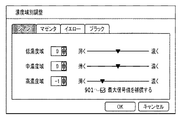
一方、上記のような最大入力濃度信号値で描画される画像に関しても濃度を薄くしたい場合が考えられる。図9は本実施形態において操作部106が表示する濃度域別調整の調整画面の例であり、最大入力濃度信号値での描画を補償するか否かの選択が可能な調整画面の一例である。図中901で示されるように最大信号値を補償するか否かを選択可能としている。すなわち、最大入力濃度信号値を補償する場合は高濃度域終点の調整は行われず、最大入力濃度信号値を補償しない場合は高濃度域終点の調整は行われることとなる。なお高濃度域終点の調整に関しては、高濃度域においての調整レベルの設定を中間点と終点の同時に設定することでより容易に調整が可能となる。
On the other hand, there may be a case where it is desired to reduce the density of an image drawn with the maximum input density signal value as described above. FIG. 9 is an example of an adjustment screen for adjustment by density region displayed by the
表3に高濃度域終点の調整が行われる際の、それぞれ中間点の調整値を示した中間点調整テーブルの例を示す。表3は、表2の中間点調整テーブルに、高濃度域終点の調整レベルが追加された例である。表3の高濃度域終点は、高濃度域の濃度を薄くする設定がされた場合に調整値を下げるように設定がされている。 Table 3 shows an example of the intermediate point adjustment table showing the adjustment values of the intermediate points when the high density area end point is adjusted. Table 3 is an example in which the adjustment level of the high density area end point is added to the midpoint adjustment table of Table 2. The end point of the high density area in Table 3 is set so that the adjustment value is lowered when the density of the high density area is set to be thin.
また図10に最大入力濃度信号値を補償する場合、しない場合の濃度調整テーブル作成の概要を示す。図10(a)は最大入力濃度信号値を補償する場合、すなわち高濃度域終点の調整を行わない場合の、線形補間テーブルである。一方、図10(b)は最大入力濃度信号値を補償しない場合、すなわち高濃度域終点の調整を行った場合の、線形補間テーブルである。 FIG. 10 shows an outline of density adjustment table creation when the maximum input density signal value is compensated or not. FIG. 10A is a linear interpolation table when the maximum input density signal value is compensated, that is, when the adjustment of the high density area end point is not performed. On the other hand, FIG. 10B is a linear interpolation table when the maximum input density signal value is not compensated, that is, when the high density area end point is adjusted.
本実施形態では、選択的に制御点を使用し、使用する制御点間を線形で補間することで、隣接するそれぞれの調整設定値が影響しあうことで発生し得る階調段差を抑制することが可能である。また本実施形態では隣接する濃度域がオーバーラップしている例を説明したが、濃度域の組み合わせによっては使用しない制御点を設定できる。例えば、低濃度域と中濃度域との隣接する2つの濃度域を調整する場合、オーバーラップしている箇所の始点と終点は使用されない。すなわち、前述したように、低濃度域と中濃度域とを一つの濃度域として扱うので、低濃度域終点および中濃度域始点は、使用する制御点として選択されない。従って、オーバーラップ領域があっても、オーバーラップ領域が無くても本実施形態は有効である。例えば本実施形態で言えば、低濃度域終点を中濃度域始点より大きく設定しオーバーラップ領域を設けたが、低濃度域終点を中濃度域始点より小さくしても本実施形形態の有効性は失われない。 In this embodiment, by selectively using control points and linearly interpolating between the control points to be used, it is possible to suppress gradation steps that may occur due to the influence of adjacent adjustment setting values. Is possible. In this embodiment, an example in which adjacent density regions overlap has been described. However, depending on the combination of density regions, control points that are not used can be set. For example, when adjusting two adjacent density regions, a low concentration region and a medium concentration region, the start point and the end point of the overlapping portion are not used. That is, as described above, since the low density area and the middle density area are handled as one density area, the low density area end point and the middle density area start point are not selected as control points to be used. Therefore, the present embodiment is effective even if there is an overlap region or no overlap region. For example, in the present embodiment, the low density area end point is set larger than the middle density area start point and the overlap area is provided. However, the effectiveness of the present embodiment can be achieved even if the low density area end point is made smaller than the middle density area start point. Will not be lost.
なお、オーバーラップ領域を設けるということは、オーバーラップ領域を設けない場合と比べて各濃度域の領域を大きく設定していることになる。各濃度域の領域が大きくなるほど調整できる幅が広がるので、画像の表現度が向上する。また、例えばオーバーラップ領域を設けない場合には、低濃度域終点及び中濃度域始点に対応する信号値については、低濃度域の調整、中濃度域の調整、低濃度域及び中濃度域の調整のいずれの場合においても調整することができない。しかしながら、オーバーラップ領域を設けることで低濃度域終点及び中濃度域始点に対応する信号値についても低濃度域の調整、中濃度域の調整、低濃度域及び中濃度域の調整のいずれの場合おいても調整することができる。従って、オーバーラップ領域を設ける利点はあるものの、前述したように、本実施形態はオーバーラップ領域がなくても適用可能である。 The provision of the overlap region means that the region of each density region is set larger than in the case where the overlap region is not provided. The larger the area of each density area, the wider the adjustable range, so that the degree of image representation is improved. For example, when the overlap area is not provided, the signal values corresponding to the low density area end point and the middle density area start point are adjusted for the low density area, the middle density area, the low density area and the middle density area. In either case of adjustment, it cannot be adjusted. However, by providing an overlap area, the signal values corresponding to the end point of the low density area and the start point of the middle density area can be adjusted either in the low density area, in the middle density area, or in the low density area or the middle density area. Can also be adjusted. Therefore, although there is an advantage of providing an overlap region, as described above, the present embodiment can be applied without an overlap region.
また、本実施形態では、中間点調整テーブルにおいて、低濃度域の中間点における最大調整時の出力信号を、低濃度域の終点の出力信号(=低濃度域の終点の入力信号)より小さい値にしている。すなわち、隣接濃度域のうち、低い方の濃度域の中間点の最大濃度レベルの出力信号を、その低い方の濃度域終点の出力信号より小さい値にしている。また、低濃度域の中間点における最大調整時の出力信号を、中濃度域の中間点における最小調整時の出力信号より小さい値にしている。すなわち、すなわち、隣接濃度域のうち、低い方の濃度域の中間点の最大濃度レベルの出力信号を、高い方の濃度域の中間点の最小濃度レベルの出力信号より小さい値にしている。このような中間点調整テーブルを用意することで容易に階調反転の発生を抑制できる。例えば、本実施形態において低濃度域制御点の最大調整出力信号は表2より85であるが、この値は低濃度域終点の出力信号(=低濃度域の終点の入力信号)の100より小さくなっている。また中濃度域中間点の最小調整時の出力信号の100よりも小さい値になっている。このため階調の反転は起きないよう制御されている。 In the present embodiment, in the intermediate point adjustment table, the output signal at the time of maximum adjustment at the intermediate point in the low density region is smaller than the output signal at the end point in the low density region (= the input signal at the end point in the low density region). I have to. That is, the output signal of the maximum density level at the midpoint of the lower density area in the adjacent density areas is set to a value smaller than the output signal of the lower density area end point. Further, the output signal at the maximum adjustment at the middle point in the low density region is set to a value smaller than the output signal at the minimum adjustment at the middle point in the middle density region. In other words, the output signal of the maximum density level at the midpoint of the lower density range in the adjacent density ranges is set to a value smaller than the output signal of the minimum density level at the midpoint of the higher density range. By preparing such an intermediate point adjustment table, occurrence of gradation inversion can be easily suppressed. For example, in this embodiment, the maximum adjustment output signal of the low density area control point is 85 from Table 2, but this value is smaller than 100 of the output signal of the low density area end point (= the input signal of the end point of the low density area). It has become. Further, the value is smaller than 100 of the output signal at the time of the minimum adjustment of the middle point in the middle density range. For this reason, control is performed so that gradation inversion does not occur.
なお、同様な制御として中濃度域中間点の最大調整時の出力信号を中濃度域終点の出力信号(=中濃度域の終点の入力信号)及び、高濃度域中間点の最小調整時の出力信号より小さい値にしておくことで階調反転の発生の抑制を可能とする。 As a similar control, the output signal at the maximum adjustment of the intermediate point in the middle density range is the output signal at the end point of the intermediate density range (= the input signal at the end point of the intermediate density range) and the output at the minimum adjustment of the intermediate point in the high density range. By making the value smaller than the signal, the occurrence of gradation inversion can be suppressed.
以上のように本実施形態によれば複数の濃度域に対して独立に濃度調整する際に、各濃度域に制御点を設定する。そして、調整を行う濃度域の組み合わせにより制御点を選択的に使用することで濃度反転の抑制と階調性の維持が簡易な構成で容易に実装可能となる。また、本実施形態では前述したような制御点選択テーブルと中間点調整テーブルを設けることで階調反転が生じないので、反転が生じているかを検出する処理も不要となる。 As described above, according to the present embodiment, when adjusting the density independently for a plurality of density areas, a control point is set for each density area. Further, by selectively using the control points according to the combination of density areas to be adjusted, it is possible to easily implement the suppression of density inversion and the maintenance of gradation properties with a simple configuration. Further, in the present embodiment, since the gradation inversion does not occur by providing the control point selection table and the intermediate point adjustment table as described above, it is not necessary to detect whether the inversion has occurred.
なお、本実施形態では制御点選択テーブルと中間点調整テーブルなど、テーブル形式のものを例に挙げて説明したが、調整濃度域と調整レベルに対応する調整値(濃度値)とが得られるものであればどのようなものであってもよい。 In this embodiment, a table format such as a control point selection table and an intermediate point adjustment table has been described as an example. However, an adjustment value (density value) corresponding to an adjustment density range and an adjustment level can be obtained. Anything may be used.
また、本実施形態では、各濃度域の個別の中間点については、濃度域の中間値の信号値に対応させている例を説明したが、必ずしも中間値でなくてもよい。 In the present embodiment, an example is described in which each intermediate point in each density region is associated with a signal value of an intermediate value in the density region. However, the intermediate point may not necessarily be an intermediate value.
<実施形態2>
実施形態1においては制御点として、各濃度域に対して始点・中間点・終点を設定し、濃度域調整の際には調整を行う濃度域の組み合わせにより制御点を選択的に使用する例を説明した。実施形態2では、更に制御点を追加することでハイライト部・シャドウ部といった、より階調再現性の求められる濃度域の濃度調整に関して容易に階調性の維持を可能とする画像処理装置を説明する。
<Embodiment 2>
In the first embodiment, the start point, the intermediate point, and the end point are set as the control points for each density area, and the control points are selectively used by combining the density areas to be adjusted when adjusting the density area. explained. In the second exemplary embodiment, an image processing apparatus that can easily maintain gradation with respect to density adjustment in a density range where more gradation reproducibility is required, such as a highlight part and a shadow part, by adding control points. explain.
実施形態2に係る画像処理装置のコントローラ構成は図1で示された実施形態1と同様のものになる。 The controller configuration of the image processing apparatus according to the second embodiment is the same as that of the first embodiment shown in FIG.
図11に実施形態2における濃度調整テーブル作成の際に使用する濃度調整の制御点の例を示す。図11において、それぞれ低・中・高濃度域に対して、始点・中間点・終点と設定されているものは、実施形態1の図6で説明した制御点と同じものとなる。一方、実施形態2では低濃度域及び高濃度域に対して、それぞれ低濃度域補助点1101、高濃度域補助点1102を追加する。低濃度域補助点1101、高濃度域補助点1102も制御点の一種である。
FIG. 11 shows an example of density adjustment control points used when creating the density adjustment table in the second embodiment. In FIG. 11, the start point, the intermediate point, and the end point set for the low, middle, and high density regions are the same as the control points described in FIG. On the other hand, in the second embodiment, a low concentration region auxiliary point 1101 and a high concentration region
実施形態2における濃度調整テーブルを作成するために使用する制御点の組み合わせを示した制御点選択テーブルを表4に示す。 Table 4 shows a control point selection table showing combinations of control points used for creating the density adjustment table in the second embodiment.
表4に示される制御点選択テーブルより、例えば低濃度域の調整を行った場合、低濃度域始点601・低濃度域中間点602・低濃度域終点604を使用するとともに低濃度域補助点1101も使用する。同様に高濃度域の調整を行った場合、高濃度域始点606・高濃度域中間点608・高濃度域終点609を使用するとともに高濃度域補助点1102も使用する。
From the control point selection table shown in Table 4, for example, when the low density area is adjusted, the low density area start
実施形態1において例えば低濃度域の調整を行った場合、低濃度域始点と低濃度域中間点との間は線形により補間処理がなされた濃度調整テーブルが作成される。しかしながらハイライト部はより高い階調再現性を求められる領域であり、線形による補間では調整が困難となるケースもある。これに対して実施形態2では、このような高い階調再現性を求められる領域に補助点を設定することでより詳細な濃度調整を可能にする。本実施形態では、低濃度補助点は低濃度域中間点よりも低い濃度を調整し、高濃度補助点は高濃度域中間点よりも高い濃度を調整する。 In the first embodiment, for example, when adjustment of the low density region is performed, a density adjustment table in which interpolation processing is linearly performed between the low density region start point and the low density region intermediate point is created. However, the highlight portion is a region where higher gradation reproducibility is required, and there are cases where adjustment is difficult by linear interpolation. On the other hand, in the second embodiment, more detailed density adjustment can be performed by setting auxiliary points in such areas where high gradation reproducibility is required. In this embodiment, the low density auxiliary point adjusts a density lower than the low density area intermediate point, and the high density auxiliary point adjusts a density higher than the high density area intermediate point.
なお各濃度域において、調整レベルの設定は補助点と中間点は同時に設定することでより容易に調整が可能となる。また、ユーザは、例えば実施形態1と同様に図4に示すような操作画面を介して調整濃度域と調整レベルとを入力すればよい。なお、図示しないが、図9に示す階調補償の例と同様にして、補助点を使うか否かをユーザからの指示に基づいて決定してもよい。 In each density region, the adjustment level can be adjusted more easily by setting the auxiliary point and the intermediate point at the same time. Further, the user may input the adjustment density range and the adjustment level via the operation screen as shown in FIG. Although not shown, whether to use the auxiliary points may be determined based on an instruction from the user in the same manner as the gradation compensation example shown in FIG.
表5は実施形態2における濃度調整を行った際の、それぞれ中間点の調整値を示した中間点調整テーブルである。 Table 5 is an intermediate point adjustment table showing adjustment values of intermediate points when density adjustment is performed in the second embodiment.
すなわち、低濃度域の調整レベルを「濃い(+)」に「+2」とした場合、低濃度域補助点も低濃度域中間点も調整レベル「+2」となり、それぞれ調整レベルが36、85となる。同様に、低濃度域の調整レベルを「薄い(−)」に「−2」とした場合、低濃度域補助点も低濃度域中間点も調整レベル「−2」となり、それぞれ調整レベルが4、20となる。 That is, when the adjustment level of the low density region is set to “+2” to “dark (+)”, both the low density region auxiliary point and the low density region intermediate point become the adjustment level “+2”, and the adjustment levels are 36 and 85, respectively. Become. Similarly, when the adjustment level of the low density area is set to “−2” in “light (−)”, the low density area auxiliary point and the low density area intermediate point are both set to the adjustment level “−2”, and the adjustment level is 4 respectively. , 20
なお、上記では制御点の追加を低濃度域・高濃度域にそれぞれ1つずつ追加したが、その限りではなく、例えば低濃度域に対して補助点を2つ用意することも可能である。 In the above description, one control point is added to each of the low concentration region and the high concentration region. However, the present invention is not limited to this. For example, two auxiliary points can be prepared for the low concentration region.
以上のように実施形態2によれば、実施形態1に加えて、より階調再現性の求められる濃度域に対しても簡易な構成で容易に階調性の維持が容易に可能となる。 As described above, according to the second embodiment, in addition to the first embodiment, it is possible to easily maintain the gradation with a simple configuration even in the density range where more gradation reproducibility is required.
<実施形態3>
濃度調整機能には、入力された色信号別に濃度特性の傾きを変化させて実施する一律調整がある。これにより入力された画像データに対し、全ての濃度域について一律に濃度調整を行うことが可能である。実施形態3では、上記一律調整のように全ての濃度域について濃度調整を行う処理と同等の効果を、濃度域調整の組み合わせにより実現する画像処理装置を説明する。
<Embodiment 3>
The density adjustment function includes a uniform adjustment performed by changing the gradient of density characteristics for each input color signal. As a result, it is possible to uniformly adjust the density of all the density ranges for the input image data. In the third embodiment, an image processing apparatus that realizes an effect equivalent to the process of performing density adjustment for all density areas as in the above-described uniform adjustment by a combination of density area adjustments will be described.
実施形態3では濃度の一律調整を複数の濃度域全てを調整ですることで実現する。実施形態3に係る画像処理装置のコントローラ構成は図1で示された実施形態1と同様のものになる。 In the third embodiment, uniform adjustment of density is realized by adjusting all of a plurality of density ranges. The controller configuration of the image processing apparatus according to the third embodiment is the same as that of the first embodiment shown in FIG.
図12(a)は実施形態3において操作部106が表示する一律濃度調整の調整画面の一例を、図12(b)は濃度域別調整の調整画面の一例を示す図である。実施形態3においては、一律濃度調整を設定した場合、連動して濃度域調整の全域が設定される。例えば図12で示したように、一律濃度調整でシアン(C)を「濃く」の方向に「+1」と設定した場合、連動して濃度域別調整のCの各濃度域の調整が「濃く」の方向に「+1」に設定される。なお、図12の例では、一律濃度調整と濃度域別調整の調整画面とが連動する例を説明した。しかしながら、図12(a)の一律濃度調整の設定がされた場合に、図12(b)に対応する処理を濃度調整処理部206内で行い、図12(b)の濃度域別調整の調整画面を表示しなくてもよい。
FIG. 12A is a diagram illustrating an example of an adjustment screen for uniform density adjustment displayed by the
なお本実施形態において、濃度調整テーブルを作成するために使用する制御点の組み合わせは表1で示される制御点選択テーブルと同等のものとすることができる。すなわち、一律濃度調整を行った場合、使用する制御点の組み合わせは低・中・高濃度域を調整した際に使われる、低濃度域始点、低濃度域中間点、中濃度域中間点、高濃度域中間点、高濃度域終点となる。これは、調整濃度域である低・中・高濃度域を一つの濃度域とした場合の、その一つの濃度域の始点(低濃度域始点)及び終点(高濃度域終点)と、その一つの濃度域に含まれる濃度域の中間点(低濃度域中間点、中濃度域中間点、高濃度域中間点、)である。 In this embodiment, the combination of control points used to create the density adjustment table can be equivalent to the control point selection table shown in Table 1. In other words, when uniform density adjustment is performed, the combination of control points used is the low density area start point, low density area midpoint, middle density area midpoint, It is the middle point of the density range and the end point of the high density range. When the low, middle, and high density regions, which are adjustment density regions, are defined as one density region, the start point (low concentration region start point) and end point (high concentration region end point) of that one density region, It is the midpoint of the density range included in one density range (low density range midpoint, middle density range midpoint, high concentration range midpoint).
図13に実施形態3における一律濃度調整を行った際の濃度調整テーブル作成の概要を示す。図13(a)は一律濃度調整で「+2」に調整した際の線形補間テーブルの例である。使用される制御点は上述にあるように、低濃度域始点、低濃度域中間点、中濃度域中間点、高濃度域中間点、高濃度域終点となる。一方図13(b)は一律濃度調整で「−2」に調整した際の線形補間テーブルの例である。なおそれぞれの中間点の調整値は表2で示されたものを使用している。 FIG. 13 shows an outline of creating a density adjustment table when uniform density adjustment is performed in the third embodiment. FIG. 13A shows an example of a linear interpolation table when the density is uniformly adjusted to “+2”. As described above, the control points to be used are the low concentration region start point, the low concentration region intermediate point, the intermediate concentration region intermediate point, the high concentration region intermediate point, and the high concentration region end point. On the other hand, FIG. 13B is an example of a linear interpolation table when the density is uniformly adjusted to “−2”. The adjustment values shown in Table 2 are used as the adjustment values for the respective intermediate points.
なお本実施形態においては、一律濃度調整で全ての濃度域について一律に濃度調整を行った後に、それぞれの濃度域に対して個別に調整も可能である。すなわち、入力された画像データに対して全体に濃度調整を行う。そして、更に濃度域ごとに詳細に調整するといった処理が可能である。例えば、全体の濃度を「−1」に設定することで、各濃度域の濃度を「−1」に設定する。その後、中間濃度域の濃度を「0」の設定に更新してもよい。 In the present embodiment, after the density adjustment is uniformly performed for all density areas by the uniform density adjustment, it is possible to individually adjust each density area. That is, density adjustment is performed on the entire input image data. Further, it is possible to perform processing such as adjusting in detail for each density range. For example, by setting the overall density to “−1”, the density of each density range is set to “−1”. Thereafter, the density in the intermediate density range may be updated to a setting of “0”.
以上のように実施形態3によれば一律濃度調整を行う際、複数の濃度域に対して独立に濃度調整する機能を利用することができる。これにより、一律濃度調整機能を別個に設けることなく、濃度域別調整機能によって一律濃度調整機能を兼用することもできる。 As described above, according to the third embodiment, when the uniform density adjustment is performed, the function of independently adjusting the density for a plurality of density ranges can be used. Thus, the uniform density adjustment function can be shared by the density area-specific adjustment function without separately providing the uniform density adjustment function.
<その他の実施例>
また、本発明は、以下の処理を実行することによっても実現される。即ち、上述した実施形態の機能を実現するソフトウェア(プログラム)を、ネットワーク又は各種記憶媒体を介してシステム或いは装置に供給し、そのシステム或いは装置のコンピュータ(またはCPUやMPU等)がプログラムを読み出して実行する処理である。
<Other examples>
The present invention can also be realized by executing the following processing. That is, software (program) that realizes the functions of the above-described embodiments is supplied to a system or apparatus via a network or various storage media, and a computer (or CPU, MPU, or the like) of the system or apparatus reads the program. It is a process to be executed.
Claims (12)
ユーザの指示に基づき、複数の濃度域のそれぞれの濃度域に対して調整レベルを入力する入力手段と、 An input means for inputting an adjustment level for each of the plurality of density ranges based on a user instruction;
前記入力手段によって調整レベルが入力された複数の濃度域の組み合わせに応じて、濃度調整に使用する濃度特性における制御点を決定する決定手段と、 Determining means for determining a control point in density characteristics used for density adjustment in accordance with a combination of a plurality of density areas whose adjustment levels are input by the input means;
前記入力手段によって入力された調整レベルに基づき、前記濃度調整に使用する濃度特性の制御点の出力濃度レベルを調整する調整手段と、 Adjusting means for adjusting the output density level of the control point of the density characteristic used for the density adjustment based on the adjustment level input by the input means;
前記調整手段によって出力濃度レベルが調整された制御点の間を補間することで濃度特性を生成する生成手段とを有し、 Generating means for generating density characteristics by interpolating between control points whose output density levels have been adjusted by the adjusting means;
前記決定手段は、前記入力手段によって調整レベルが入力された複数の濃度域が互いに隣接する濃度域の場合、前記濃度域において隣接する側に位置する濃度域の端点以外の点から前記制御点を決定すること In the case where the plurality of density regions whose adjustment levels are input by the input unit are adjacent to each other, the determining unit determines the control point from a point other than the end point of the density region located on the adjacent side in the density region. To decide
を特徴とする画像処理装置。 An image processing apparatus.
前記決定手段は、前記選択テーブルを用いて前記制御点を決定し、 The determining means determines the control point using the selection table,
前記調整手段は、前記制御点調整テーブルを用いて前記制御点の出力濃度レベルを調整する The adjusting means adjusts the output density level of the control point using the control point adjustment table.
ことを特徴とする請求項1から7のいずれか一項に記載の画像処理装置。 The image processing apparatus according to claim 1, wherein the image processing apparatus is an image processing apparatus.
ユーザの指示に基づき、複数の濃度域のそれぞれの濃度域に対して調整レベルを入力する入力工程と、 An input process for inputting an adjustment level for each of the plurality of density ranges based on a user instruction;
前記入力工程において調整レベルが入力された複数の濃度域の組み合わせに応じて、濃度調整に使用する濃度特性における制御点を決定する決定工程と、 A determination step of determining a control point in the density characteristic used for density adjustment according to a combination of a plurality of density ranges in which the adjustment level is input in the input step;
前記入力工程において入力された調整レベルに基づき、前記濃度調整に使用する濃度特性の制御点の出力濃度レベルを調整する調整工程と、 An adjustment step of adjusting an output density level of a control point of density characteristics used for the density adjustment based on the adjustment level input in the input step;
前記調整工程において出力濃度レベルが調整された制御点の間を補間することで濃度特性を生成する生成工程とを有し、 A generation step of generating a density characteristic by interpolating between control points whose output density levels are adjusted in the adjustment step;
前記決定工程において、前記入力工程において調整レベルが入力された複数の濃度域が互いに隣接する濃度域の場合、前記濃度域において隣接する側に位置する濃度域の端点以外の点から前記制御点が決定されること In the determining step, when the plurality of density regions to which the adjustment level is input in the input step are adjacent to each other, the control point is determined from a point other than the end point of the density region located on the adjacent side in the density region. To be determined
を特徴とする画像処理方法。 An image processing method characterized by the above.
Priority Applications (3)
| Application Number | Priority Date | Filing Date | Title |
|---|---|---|---|
| JP2013210404A JP6223107B2 (en) | 2013-10-07 | 2013-10-07 | Image processing apparatus, image processing method, and program |
| US14/499,882 US9398194B2 (en) | 2013-10-07 | 2014-09-29 | Image processing apparatus and method performing density adjustment on image data based on generated density characteristics data |
| CN201410514400.4A CN104519237B (en) | 2013-10-07 | 2014-09-29 | Image processing apparatus and image processing method |
Applications Claiming Priority (1)
| Application Number | Priority Date | Filing Date | Title |
|---|---|---|---|
| JP2013210404A JP6223107B2 (en) | 2013-10-07 | 2013-10-07 | Image processing apparatus, image processing method, and program |
Publications (3)
| Publication Number | Publication Date |
|---|---|
| JP2015075834A JP2015075834A (en) | 2015-04-20 |
| JP2015075834A5 JP2015075834A5 (en) | 2016-11-24 |
| JP6223107B2 true JP6223107B2 (en) | 2017-11-01 |
Family
ID=52776722
Family Applications (1)
| Application Number | Title | Priority Date | Filing Date |
|---|---|---|---|
| JP2013210404A Active JP6223107B2 (en) | 2013-10-07 | 2013-10-07 | Image processing apparatus, image processing method, and program |
Country Status (3)
| Country | Link |
|---|---|
| US (1) | US9398194B2 (en) |
| JP (1) | JP6223107B2 (en) |
| CN (1) | CN104519237B (en) |
Families Citing this family (3)
| Publication number | Priority date | Publication date | Assignee | Title |
|---|---|---|---|---|
| JP5932068B1 (en) * | 2015-01-06 | 2016-06-08 | オリンパス株式会社 | Image processing apparatus, imaging apparatus, image processing method, and image processing program |
| JP7183937B2 (en) * | 2019-04-25 | 2022-12-06 | セイコーエプソン株式会社 | Color conversion information generation method, color conversion information generation program, and color conversion information generation device |
| CN113380386B (en) * | 2021-06-17 | 2024-04-23 | 南阳柯丽尔科技有限公司 | Medical electronic film image adjusting method, device, equipment and storage medium |
Family Cites Families (20)
| Publication number | Priority date | Publication date | Assignee | Title |
|---|---|---|---|---|
| US5760913A (en) * | 1996-02-12 | 1998-06-02 | Splash Technology, Inc. | Color calibration method and system having independent color scanner profiles |
| US6804025B1 (en) * | 1999-03-24 | 2004-10-12 | Brother Kogyo Kabushiki Kaisha | Calibration data preparing system |
| KR100490405B1 (en) * | 2002-07-02 | 2005-05-17 | 삼성전자주식회사 | Method for adjusting image color in printing system and graphical user interface therefor |
| JP4453817B2 (en) * | 2003-12-19 | 2010-04-21 | セイコーエプソン株式会社 | Color image data correction apparatus, color image data correction method, and color correction table creation program. |
| JP4664809B2 (en) * | 2005-03-01 | 2011-04-06 | 株式会社リコー | Color image processing apparatus and color printer system |
| JP2007166543A (en) * | 2005-12-16 | 2007-06-28 | Canon Inc | Image processing device and method thereof |
| JP2007183342A (en) * | 2006-01-05 | 2007-07-19 | Nec Electronics Corp | Data converting circuit and display device using the same |
| JP4956356B2 (en) * | 2007-10-02 | 2012-06-20 | キヤノン株式会社 | Image processing apparatus and image processing method |
| JP4994203B2 (en) * | 2007-11-29 | 2012-08-08 | 株式会社リコー | Image processing device |
| JP2009285914A (en) * | 2008-05-28 | 2009-12-10 | Konica Minolta Business Technologies Inc | Image forming device, and uneven-density-corrected image generating method |
| JP5055315B2 (en) | 2009-03-10 | 2012-10-24 | キヤノン株式会社 | Image processing apparatus and control method thereof |
| JP5517569B2 (en) | 2009-11-13 | 2014-06-11 | キヤノン株式会社 | Image processing apparatus and image processing method |
| JP5247671B2 (en) * | 2009-12-22 | 2013-07-24 | ルネサスエレクトロニクス株式会社 | Display data correction device, display panel driver using the same, and display device |
| JP5484085B2 (en) * | 2010-01-18 | 2014-05-07 | キヤノン株式会社 | Image forming apparatus and image quality correction method thereof |
| JP5896610B2 (en) * | 2011-03-14 | 2016-03-30 | キヤノン株式会社 | Apparatus, method and program |
| JP5814612B2 (en) * | 2011-05-11 | 2015-11-17 | キヤノン株式会社 | Image processing apparatus, image processing method, and program |
| JP2012247924A (en) * | 2011-05-26 | 2012-12-13 | Canon Inc | Image processing apparatus, image processing method, and program |
| JP5885422B2 (en) | 2011-08-11 | 2016-03-15 | キヤノン株式会社 | Image processing apparatus and image processing method |
| US9781309B2 (en) * | 2012-02-06 | 2017-10-03 | Apple Inc. | Editing media using composite bumps |
| JP2015011206A (en) * | 2013-06-28 | 2015-01-19 | 株式会社沖データ | Image forming apparatus and control program |
-
2013
- 2013-10-07 JP JP2013210404A patent/JP6223107B2/en active Active
-
2014
- 2014-09-29 US US14/499,882 patent/US9398194B2/en active Active
- 2014-09-29 CN CN201410514400.4A patent/CN104519237B/en active Active
Also Published As
| Publication number | Publication date |
|---|---|
| US9398194B2 (en) | 2016-07-19 |
| CN104519237A (en) | 2015-04-15 |
| CN104519237B (en) | 2018-08-10 |
| JP2015075834A (en) | 2015-04-20 |
| US20150098098A1 (en) | 2015-04-09 |
Similar Documents
| Publication | Publication Date | Title |
|---|---|---|
| US10706340B2 (en) | Image processing apparatus and method for controlling the same with character attribute indicating that pixel is pixel of a character | |
| JP5885422B2 (en) | Image processing apparatus and image processing method | |
| KR20100105497A (en) | Image processing apparatus and control method of image forming apparatus | |
| KR101810285B1 (en) | Image processing apparatus, image processing method, and computer program | |
| JP2016046606A (en) | Image processing apparatus, image forming apparatus, image processing method, and program | |
| JP6613115B2 (en) | Image processing apparatus, image processing method, and program | |
| US20130021624A1 (en) | Image processing apparatus, image forming apparatus, image processing method, and computer-readable medium | |
| JP5863001B2 (en) | Image processing apparatus, image forming apparatus, and program | |
| JP6223107B2 (en) | Image processing apparatus, image processing method, and program | |
| US9218552B2 (en) | Image processing apparatus and image processing method | |
| JP6702685B2 (en) | Image forming apparatus, image forming apparatus control method, and program | |
| JP6452342B2 (en) | Image processing apparatus, image forming apparatus, image processing method, and program | |
| JP2011004277A (en) | Image forming apparatus | |
| US10178278B2 (en) | Image forming apparatus that applies correction selectively to a subset of pixels | |
| JP2009253956A (en) | Image processing apparatus | |
| US20170353627A1 (en) | Image processing apparatus, method, and storage medium using color-adjusted image data | |
| US10404892B2 (en) | Image forming apparatus for outputting a halftone image and image forming method | |
| JP5885489B2 (en) | Image processing apparatus, image processing method, and computer program | |
| US10560603B2 (en) | Image processing apparatus and image processing method | |
| JP2018107649A (en) | Image processing device and computer program | |
| JP6155646B2 (en) | Image forming apparatus and image processing method | |
| JP2015220742A (en) | Image processing system, image forming apparatus, and control method for them | |
| JP2012205220A (en) | Gradation conversion controller, image processing device, and program |
Legal Events
| Date | Code | Title | Description |
|---|---|---|---|
| A521 | Request for written amendment filed |
Free format text: JAPANESE INTERMEDIATE CODE: A523 Effective date: 20161007 |
|
| A621 | Written request for application examination |
Free format text: JAPANESE INTERMEDIATE CODE: A621 Effective date: 20161007 |
|
| A977 | Report on retrieval |
Free format text: JAPANESE INTERMEDIATE CODE: A971007 Effective date: 20170829 |
|
| TRDD | Decision of grant or rejection written | ||
| A01 | Written decision to grant a patent or to grant a registration (utility model) |
Free format text: JAPANESE INTERMEDIATE CODE: A01 Effective date: 20170905 |
|
| A61 | First payment of annual fees (during grant procedure) |
Free format text: JAPANESE INTERMEDIATE CODE: A61 Effective date: 20171003 |
|
| R151 | Written notification of patent or utility model registration |
Ref document number: 6223107 Country of ref document: JP Free format text: JAPANESE INTERMEDIATE CODE: R151 |