JP6221986B2 - Pouch - Google Patents
Pouch Download PDFInfo
- Publication number
- JP6221986B2 JP6221986B2 JP2014154093A JP2014154093A JP6221986B2 JP 6221986 B2 JP6221986 B2 JP 6221986B2 JP 2014154093 A JP2014154093 A JP 2014154093A JP 2014154093 A JP2014154093 A JP 2014154093A JP 6221986 B2 JP6221986 B2 JP 6221986B2
- Authority
- JP
- Japan
- Prior art keywords
- edge
- pouch
- region
- outer edge
- seal
- Prior art date
- Legal status (The legal status is an assumption and is not a legal conclusion. Google has not performed a legal analysis and makes no representation as to the accuracy of the status listed.)
- Active
Links
Images


Description
本発明は、重ねられた積層フィルムをヒートシールすることにより製袋されるパウチに関する。 The present invention relates to a pouch that is bag-formed by heat-sealing stacked laminated films.
例えばレトルト食品や冷凍食品を内容物とした電子レンジ用のパウチが広く利用に供されている。このパウチを電子レンジ内で温めると、加熱に伴って内容物に含まれる水分が蒸発してパウチ内の圧力が高まっていく。パウチ内の圧力が高まると、パウチが破袋して内容物が飛散し電子レンジ内を汚してしまうおそれがある。 For example, pouches for microwave ovens that contain retort foods or frozen foods are widely used. When this pouch is warmed in the microwave oven, moisture contained in the contents evaporates with heating, and the pressure in the pouch increases. When the pressure in the pouch increases, the pouch may break and the contents may scatter and contaminate the microwave oven.
そこで、特許文献1に記載されているように、加熱に伴って発生する蒸気を袋の外部へ逃がすべく、パウチの一部にリング状のヒートシール領域を設け、当該ヒートシール領域に囲まれた部分に蒸気抜き孔を空けたパウチが知られている。特許文献1に記載のパウチによれば、加熱に伴ってパウチ内の圧力が高まると、リング状のヒートシール領域が剥がれて、パウチ内の収容空間がリング状のヒートシール領域内の蒸気抜き孔に通じる。これにより、パウチ内の蒸気を蒸気抜き孔から外部へ逃がすことができる。 Therefore, as described in Patent Document 1, a ring-shaped heat seal region is provided in a part of the pouch so as to escape the steam generated with heating to the outside of the bag, and is surrounded by the heat seal region. A pouch with a steam vent in the part is known. According to the pouch described in Patent Document 1, when the pressure in the pouch increases with heating, the ring-shaped heat seal region is peeled off, and the accommodation space in the pouch becomes a steam vent hole in the ring-shaped heat seal region. Leads to Thereby, the vapor | steam in a pouch can be escaped outside from a vapor | steam vent hole.
あるいは、特許文献2に記載されているように、ヒートシールされた側縁に切欠きを設け、当該切欠きの周りをヒートシールしたパウチも知られている。特許文献2に記載のパウチでは、切欠きの周りに形成されたヒートシール領域の一部に、易剥離性を示す材料を用いている。このため、加熱に伴ってパウチ内の圧力が高まると、易剥離性を示す材料にて形成されたヒートシール領域から剥離し、パウチ内の収容空間がパウチ外部に通じる。
これにより、パウチ内の蒸気を切欠きから外部へ逃がすことができる。
Alternatively, as described in
Thereby, the vapor | steam in a pouch can be escaped from a notch to the exterior.
しかしながら、特許文献1に記載のパウチでは、リング状のヒートシール領域に囲まれた所定の位置に蒸気抜き孔が確実に空けられたかについて、検査する必要がある。加えて、商品性を損ねることがないよう、蒸気抜き孔を空ける際に生成される抜きカスを確実に回収する必要もある。さらに、蒸気抜き孔の位置のばらつきを吸収するために、リング状のヒートシール領域を大きく確保する必要があり、この結果、内容物をパウチ内に充填する間口を広く確保することができず、内容物を容易に充填することができない。 However, in the pouch described in Patent Document 1, it is necessary to inspect whether or not the steam vent is surely opened at a predetermined position surrounded by the ring-shaped heat seal region. In addition, it is also necessary to reliably recover the slag generated when the steam vent hole is opened so as not to impair the merchantability. Furthermore, in order to absorb the variation in the position of the steam vent hole, it is necessary to ensure a large ring-shaped heat seal area, and as a result, it is not possible to ensure a wide opening for filling the contents in the pouch, The contents cannot be filled easily.
一方、特許文献2に記載のパウチでは、上記の問題に対しては有効なものの、易剥離性を示す材料を部分的に設ける必要があり、積層フィルムの材料コスト及び製造コストが高くなってしまう。さらに、切欠きは、パウチをなすようになる積層フィルムを個別の型を用いて裁断してから、その周縁近傍をヒートシールすることによって作製される。このため、個別の型を準備するために費用がかかり、パウチの製造コストが益々高くなってしまう。これらの結果、市場で競争力のある価格で、特許文献2に記載のパウチを提供することはできない。
On the other hand, the pouch described in
本発明は、このような点を考慮してなされたものであり、安価で容易に製造可能なヒートシールによって製袋されるパウチを提供することを目的とする。 The present invention has been made in view of such points, and an object of the present invention is to provide a pouch that is made by heat sealing at a low cost and can be easily manufactured.
本発明によるパウチは、重ねられた積層フィルムをヒートシールすることにより製袋され、内容物を収容する収容空間と当該収容空間の周りを取り囲む周囲領域とを有するパウチであって、
前記周囲領域は、重ねられた積層フィルムがヒートシールされたシール領域と、前記シール領域によって前記収容空間から隔離され、重ねられた積層フィルムがヒートシールされていない第1未シール領域と、を有しており、
前記第1未シール領域には、重ねられた積層フィルムの縁部によって規定される開口が形成されており、
前記第1未シール領域の縁部は、前記開口の周りから前記収容空間側に延び出た第1縁部及び第2縁部と、前記第1縁部の先端と前記第2縁部の先端との間を延びる第3縁部と、を含み、
前記シール領域は、当該パウチの外縁に沿って前記第1未シール領域の前記第1縁部まで延びる第1外縁シール部分と、当該パウチの外縁に沿って前記第1未シール領域の前記第2縁部まで延びる第2外縁シール部分と、前記第1外縁シール部分と前記第2外縁シール部分との間に位置し、前記第1外縁シール部分及び前記第2外縁シール部分よりも前記収容空間に向けて張り出した張出部と、を有し、
前記張出部は、前記第1縁部の一部分及び第3縁部に隣接しており、
前記張出部は、前記第1外縁シール部分に対して3mm以上の大きさの段差を形成し、 前記シール領域の前記張出部の巾は、前記シール領域の前記張出部以外の部分の巾よりも狭い。
The pouch according to the present invention is a pouch that is made by heat-sealing the laminated film that has been stacked, and has a storage space for storing contents and a surrounding region surrounding the storage space,
The surrounding area has a sealed area where the laminated film is heat-sealed and a first unsealed area which is isolated from the accommodation space by the sealed area and the laminated film is not heat-sealed. And
In the first unsealed region, an opening defined by the edge of the laminated film that is overlaid is formed,
The edge of the first unsealed region includes a first edge and a second edge extending from the periphery of the opening toward the housing space, a tip of the first edge, and a tip of the second edge. A third edge extending between and
The seal area includes a first outer edge seal portion that extends along an outer edge of the pouch to the first edge of the first unsealed area, and a second outer edge of the first unsealed area along the outer edge of the pouch. A second outer edge seal portion extending to the edge, and is positioned between the first outer edge seal portion and the second outer edge seal portion, and is located in the receiving space more than the first outer edge seal portion and the second outer edge seal portion. And a projecting portion projecting toward the
The overhang is adjacent to a portion of the first edge and a third edge;
The projecting portion forms a step having a size of 3 mm or more with respect to the first outer edge seal portion, and the width of the projecting portion of the seal region is that of a portion other than the projecting portion of the seal region. Narrower than the width.
本発明によるパウチにおいて、前記第1未シール領域の前記第1縁部は、前記第2縁部に対して平行に延び、
前記第1縁部の長さは、前記第2縁部の長さと等しくてもよい。
In the pouch according to the present invention, the first edge of the first unsealed region extends parallel to the second edge,
The length of the first edge may be equal to the length of the second edge.
本発明によるパウチにおいて、前記シール領域の前記張出部のシール強さは、100℃で35N/15mm以下であってもよい。 In the pouch according to the present invention, the seal strength of the protruding portion of the seal region may be 35 N / 15 mm or less at 100 ° C.
本発明によるパウチにおいて、前記周囲領域のうち、前記収容空間を挟んで前記第1未シール領域に対面する位置に、前記シール領域によって前記収容空間から隔離された第2未シール領域が設けられ、
前記第2未シール領域には、重ねられた積層フィルムの縁部によって規定される開口が形成され、
前記第2未シール領域と前記収容空間との間に位置する部分のシール領域の巾は、前記張出部の巾よりも広くてもよい。
In the pouch according to the present invention, a second unsealed area separated from the accommodation space by the seal area is provided at a position facing the first unsealed area across the accommodation space in the surrounding area.
In the second unsealed region, an opening defined by the edge of the laminated film that is overlaid is formed,
The width of the seal region at the portion located between the second unsealed region and the accommodation space may be wider than the width of the overhanging portion.
本発明によるパウチにおいて、前記第1外縁シール部分の巾は、前記第2外縁シール部分の巾よりも狭くてもよい。 In the pouch according to the present invention, the width of the first outer edge seal portion may be narrower than the width of the second outer edge seal portion.
本発明によるパウチにおいて、前記第2外縁シール部分にノッチが形成されていてもよい。 In the pouch according to the present invention, a notch may be formed in the second outer edge seal portion.
本発明によるパウチにおいて、前記張出部は、前記第2縁部の一部分にも隣接しており、
前記張出部は、前記第2外縁シール部分に対しても段差を形成していてもよい。
In the pouch according to the present invention, the overhanging portion is also adjacent to a part of the second edge portion,
The projecting portion may form a step with respect to the second outer edge seal portion.
本発明によるパウチにおいて、前記張出部は、前記第2外縁シール部分と平坦に繋がっていてもよい。 In the pouch according to the present invention, the projecting portion may be connected flatly to the second outer edge seal portion.
本発明によれば、ヒートシールによって製袋されるパウチを安価で容易に製造することができる。 According to the present invention, a pouch made by heat sealing can be easily manufactured at a low cost.
以下、図面を参照して本発明の一実施の形態について説明する。なお、本件明細書に添付する図面においては、図示と理解のしやすさの便宜上、適宜縮尺及び縦横の寸法比等を、実物のそれらから変更し誇張してある。図1は、本発明の一実施の形態によるパウチの一例を示す平面図である。 Hereinafter, an embodiment of the present invention will be described with reference to the drawings. In the drawings attached to the present specification, for the sake of illustration and ease of understanding, the scale, the vertical / horizontal dimension ratio, and the like are appropriately changed and exaggerated from those of the actual product. FIG. 1 is a plan view showing an example of a pouch according to an embodiment of the present invention.
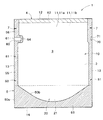
図1に示すパウチ1は、胴部10と底部20とをヒートシールして形成されるスタンディング形式のパウチである。図1に示すように、胴部10は、互いに対向して配置された表主面シート11aと裏主面シート11bとからなる一対の主面シート11を含んでおり、重ね合せられた一対の主面シート11の側縁13近傍が互いにヒートシールされている。一対の主面シート11の下縁14間に、底部20をなす底面シート21が配置されている。そして、一対の主面シート11と底面シート21とによって囲まれる空間内に、内容物を収容する収容空間2が区画されている。底面シート21は、収容空間2側に向かって凸となるように曲げられ、その周縁近傍を、重なり合う主面シート11の下部とともにヒートシールされている。底面シート21が一対の主面シート11の下端の形状を保持することによって、パウチ1に自立性を付与している。
A pouch 1 shown in FIG. 1 is a standing type pouch formed by heat-sealing a
また、図1に示すように、パウチ1では、一対の主面シート11の上縁12間に開口4が形成され、当該開口4から内容物が充填されるようになっている。内容物が充填された後、開口4が設けられた上縁12近傍をヒートシールすることにより密閉して、パウチ1が得られる。
As shown in FIG. 1, in the pouch 1, an opening 4 is formed between the
図1に示すスタンディング形式のパウチ1において、重なり合う胴部10をなす一対の主面シート11の上縁12と、重なり合う一対の主面シート11の側縁13と、重なり合う主面シート11の下縁14及び底面シート21の縁部と、によって、パウチ1の外縁5が規定されている。
In the standing type pouch 1 shown in FIG. 1, the
(積層フィルム)
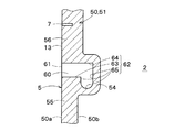
本実施の形態では、胴部10をなす一対の主面シート11及び底部20をなす底面シート21は、積層フィルム30からなる。図2に、積層フィルム30の層構成を示す。上述のように、パウチ1は、一対の主面シート11及び底面シート21をなす積層フィルム30をヒートシールすることによって製袋される。このため、積層フィルム30には、容器内方側となる部分にシール性を有するシーラント層34が設けられている。また、電子レンジ用のパウチ1では、印刷基材となる基材層31が、シーラント層34よりも容器外方側となる部分に設けられている。さらに、積層フィルム30は、電子レンジ用のパウチに要求される種々の機能を付与すべく、中間層33を含んでいる。したがって、このような層構成を持つ積層フィルム30は、製袋してパウチ1とするときの容器外方となる側から容器内方となる側に向けて基材層31と中間層33とシーラント層34とをこの順で含んでいる。以下、各層について詳述していく。
(Laminated film)
In the present embodiment, the pair of main surface sheets 11 forming the
上述したように、電子レンジ用のパウチ1は、熱に対する耐性を必要とされる。このため、本実施の形態の基材層31は、耐熱性をもつ材料からなる。例えば、基材層31として、延伸ポリエチレンテレフタレートフィルム、シリカ蒸着延伸ポリエチレンテレフタレートフィルム、アルミナ蒸着延伸ポリエチレンテレフタレートフィルム、延伸ナイロンフィルム、延伸ポリプロピレンフィルム、またはポリプロピレン/エチレンービニルアルコール共重合体共押共延伸フィルム、またはこれらの2以上のフィルムを積層した複合フィルムを用いることができる。
As described above, the microwave pouch 1 is required to have heat resistance. For this reason, the
好ましくは、基材層31は、二軸延伸処理される。これにより、基材層31をなす分子が、延伸処理によって延伸方向に並び、基材層31が優れた寸法安定性を発揮するようになる。また、二軸延伸処理によって、基材層31に易開封性を付与することができる。
Preferably, the
このような基材層31の厚みは、例えば10〜50μm程度に形成される。この場合、パウチ1に要求される耐熱性を満たしつつ、製品コストを抑えることができる。なお、本実施の形態の基材層31は、積層フィルム30のうち、製袋してパウチ1とするときの最も容器外方となる層としても機能する。
Such a
また、図2に示すように、本実施の形態では、基材層31の容器内方側となる面に、絵柄を含む絵柄層32が積層されている。ここで、絵柄とは、基材層31に記録または印刷され得る種々の態様の記録対象のことであり、特に限定されることなく、図、文字、模様、パターン、記号、柄、マーク等を広く含む。とりわけ、食品を内包することが意図されたパウチ1に用いられる積層フィルム30では、絵柄として、内容物の図や、内容物の商品名、賞味期限、製造日、製造番号等の情報を示す文字が用いられる。もっとも、絵柄層32は、商品の仕様に応じて基材層31に積層されるものであり、基材層31に絵柄層32が設けられなくてもよい。
As shown in FIG. 2, in the present embodiment, a
本実施の形態では、絵柄層32は、容器外方側となる基材層31の外面ではなく、基材層31の内面に施される。この場合、絵柄層32は、耐摩耗性に優れることから擦れ等による消失を効果的に防止することができ、且つ、絵柄の改ざんも効果的に防止することができる。また、製袋してパウチ1としたときに、基材層31の内面に積層された絵柄層32を基材層31を介して視認し得るよう、基材層31は透明性を有していることが好ましい。
In the present embodiment, the
シーラント層34は、上述したように、2つの積層フィルム30同士を重ね合わせて対向する縁部近傍をヒートシールすることで、当該縁部を貼り合わせて密封するために設けられている。また、本実施の形態では、シーラント層34は、積層フィルム30のうち、製袋してパウチ1とするときの最も容器内方となる側に配置される。
As described above, the
このようなシーラント層34としては、ポリエチレン、ポリプロピレン、エチレン−酢酸ビニル共重合体、エチレン−プロピレンブロック共重合体などのポリオレフィン系樹脂からなる耐熱性のあるフィルム及びイージーピールフィルムなどが採用できる。更に、これらの材料からなるフィルムによって単層としてシーラント層34が構成されてもよいし、あるいは、複数の前記材料からなるフィルムによって多層としてシーラント層34が構成されてもよい。
As such a
とりわけ、電子レンジ用のパウチなど耐熱性が要求されるパウチ1に積層フィルム30を適用する場合には、シーラント層34は、主として無延伸ポリプロピレン(CPP)を含む無延伸ポリプロピレン層(CPP層)、または、主として直鎖状低密度ポリエチレン(LLDPE)を含む直鎖状低密度ポリエチレン層(LLDPE層)を有することが好ましい。
In particular, when the
シーラント層34の厚みは、40μm以上200μm以下の範囲にあるのが好ましい。
この場合、パウチ1の流通過程において生じ得る落下に対する耐衝撃強度に優れると共に、内容物の充填し易さ、内容物の詰替え易さといった取扱性にも優れる。
The thickness of the
In this case, the impact resistance against dropping that may occur in the distribution process of the pouch 1 is excellent, and handling properties such as easy filling of contents and easy refilling of contents are also excellent.
一方、基材層31とシーラント層34との間に積層された中間層33は、電子レンジ用のパウチに要求される種々の機能を補なうために設けられている。上記の通り、パウチ1は、食品を内容物として内包することに適したパウチである。このため、内容物の酸化等の変質を防止しながら内容物を保存することができるように、中間層33は、水蒸気の透過を防止する蒸気バリア性及び酸素ガス等のガスの透過を防止するガスバリア性を有していてもよい。また、スタンディングパウチ形式のパウチ1は、売り場の商品棚に自立した状態で陳列される。パウチ1が商品棚から落下した際の衝撃等にも十分に耐え得るよう、中間層33は、耐屈曲性及び耐衝撃性を有していてもよい。また、中間層33は、消費者の購買意欲を高めるために、パウチ1の内容物が見えないように隠蔽性を十分に高める機能を有していてもよい。
On the other hand, the
このような機能をもつ中間層33として、例えば、ポリエチレンテレフタレート、ポリアミド、ポリエチレン、ポリプロピレン等のポリオレフィン、ポリ塩化ビニル、ポリカーボネート、ポリビニルアルコール、エチレンープロピレン共重合体、エチレンー酢酸ビニル共重合体ケン化物等のフィルムあるいはこれらにポリ塩化ビニリデンを塗工したフィルムないしは酸化珪素、酸化アルミニウム等の無機物の蒸着を施したフィルムあるいはポリ塩化ビニリデン等のフィルムを用いることができる。また、これら基材の一種ないしそれ以上を組み合わせて使用してもよい。
Examples of the
図2に示すように、本実施の形態では、基材層31と中間層33との間、及び、中間層33とシーラント層34との間に接合層35が介在されている。この接合層35としては、例えばそれ自体既知のドライラミネート法にて一般に用いられる接着剤を用いることができ、例えば、ポリ酢酸ビニル系接着剤、ポリアクリル酸エステル系接着剤、シアノアクリレート系接着剤、エチレン共重合体系接着剤、セルロース系接着剤、ポリエステル系接着剤、ポリアミド系接着剤、アミノ樹脂系接着剤、エポキシ系接着剤、ポリウレタン系接着剤等を用いることができる。
As shown in FIG. 2, in the present embodiment, a
(周囲領域) (Ambient area)
このような積層フィルム30からなる一対の主面シート11及び底面シート21によって周囲領域3が画成される。一対の主面シート11と底面シート21とからなる周囲領域3は、内容物を収容する収容空間2を取り囲んでいる。図1に示すように、周囲領域3は、重ねられた積層フィルム30がヒートシールされたシール領域50と、シール領域50によって収容空間2から隔離され、重ねられた積層フィルム30がヒートシールされていない第1未シール領域60と、を有している。
The
このうち、第1未シール領域60は、電子レンジによる加熱に伴って発生する蒸気によってパウチ内の圧力が高まった際に、収容空間2と連通してパウチ内の蒸気を外部へ逃がすために設けられている。第1未シール領域60は、パウチ1の外縁5から、収容空間2側に張り出している。本実施の形態の第1未シール領域60は、ヒートシールされない重ねられた主面シート11をなす積層フィルム30からなる。従って、第1未シール領域60には、重ねられた積層フィルム30の縁部によって規定される開口61が形成されている。図示する例では、開口61は、重ねられた一対の主面シート11の側縁13によって形成されている。なお、第1未シール領域60の全域が、主面シート11をなす積層フィルム30に覆われていなくてもよく、第1未シール領域60内に位置する各主面シート11の一部に孔や切り抜きを設けてもよい。
Among these, the first unsealed
図3に、図1に示すパウチ1の第1未シール領域60を拡大して示す。図3に示すように、第1未シール領域60の縁部62は、開口61の周りから収容空間2側に延び出た第1縁部63及び第2縁部64と、第1縁部63の先端と第2縁部64の先端との間を延びる第3縁部65と、を含んでいる。図示する例では、主面シート11の下縁14側に第1縁部63が配置されており、主面シート11の上縁12側に第2縁部64が配置されている。もっとも、主面シート11の上縁12側に第1縁部63が配置され、主面シート11の下縁14側に第2縁部64が配置されてもよい。
FIG. 3 shows an enlarged view of the first unsealed
図3に示すように、第1未シール領域60の第1縁部63及び第2縁部64は、パウチ1の外縁5に交差する方向、より詳細には直交する方向に直線状に延び出している。本実施の形態では、第1縁部63は、第2縁部64に対して平行に延びている。加えて、第1縁部63の長さL1は、第2縁部64の長さL2と等しい。従って、第3縁部65が、第1縁部63の先端と第2縁部64の先端との間を直線状に延びる場合、第3縁部65は、パウチ1の外縁5に平行に延び、第1縁部63及び第2縁部64と直交する。この場合、第1未シール領域60の縁部62は、略コの字状の形状に沿って延びるようになる。本実施の形態では、第3縁部65の長さL3は、第1縁部63の長さL1及び第2縁部64の長さL2よりも短い。
As shown in FIG. 3, the
なお、図示する例では、第1縁部63、第2縁部64及び第3縁部65が、直線状に延び出す例を示したが、曲線状の経路に沿って延び出してもよい。また、第1縁部63は、第2縁部64に対して非平行に延びてもよいし、第2縁部64と異なる長さであってもよい。図4及び図5に、第1未シール領域60の縁部62が延びる経路の他の例を示す。図4に示す例では、第3縁部65は、第1縁部63の先端と第2縁部64の先端との間を曲線状の経路に沿って延びている。具体的には、第3縁部65は、収容空間2側に凸となるように曲線状の経路に沿って延びている。言い換えると、第3縁部65は、第1縁部63の先端と第2縁部64の先端とを結ぶ仮想直線よりも、収容空間2に近接した領域内で曲線状の経路に沿って延びている。
In the illustrated example, the
あるいは、図5に示す例では、第1未シール領域60は、パウチ1の外縁5から、収容空間2側に張り出した後、下縁14側に向かってさらに張り出している。具体的には、第3縁部65は、第1縁部63の先端から下縁14側に向かってU字状の経路に沿って延びた後、第2縁部64の先端に向かって直線状の経路に沿って延びている。
Alternatively, in the example shown in FIG. 5, the first unsealed
ところで、第1未シール領域60の縁部62を、略V字状の形状に沿って延びるように形成することも考えられる。言い換えると、第1未シール領域60の縁部が、開口61の周りから収容空間2側に延び出た第1縁部及び第2縁部のみからなり、第1縁部の先端と第2縁部の先端とを重ねた形態も考えられる。しかしながら、この場合、輸送時や保管時に意図しない振動や衝撃がパウチに伝わると、第1縁部の先端と第2縁部の先端との交点付近に集中的に大きな負荷がかかり、当該交点付近からシール領域50に剥離が生じてしまうおそれがある。一方、本実施の形態では、第1未シール領域60の縁部62は、第1縁部63の先端と第2縁部64の先端との間を延びる第3縁部65をさらに含んでいる。
このため、輸送時や保管時に意図しない振動や衝撃がパウチに伝わっても、第1縁部63の先端と第2縁部64の先端との間に集中的に大きな負荷がかかることはなく、第3縁部65に隣接するシール領域50の部分(後述する張出部54)に剥離が生じることを防止することができる。
By the way, it is also conceivable to form the
For this reason, even if an unintended vibration or impact is transmitted to the pouch during transportation or storage, a large load is not intensively applied between the tip of the
一方、シール領域50は、重ねられた積層フィルム30をヒートシールすることによって、内容物を収容する収容空間2を密閉する機能を有している。上述のように、シール領域50は、重ねられた積層フィルム30の周縁近傍をヒートシールすることにより形成され、主面シート11及び底面シート21は、同一の積層フィルム30から構成されている。従って、同一のヒートシール条件下で、重ねられた積層フィルム30の周縁近傍をヒートシールした場合、シール領域50内の任意の一地点における接合力は、他の一地点の接合力と等しくなる。このため、加熱に伴ってパウチ1内の圧力が高まったときのシール領域50の剥離のし易さは、シール領域50の位置や形状等に起因して誘引される応力集中、並びに、シール領域50の巾に大きく依存する。
On the other hand, the seal | sticker area |
図1に示すように、シール領域50の外縁50aは、主面シート11の縁部12〜14、第1未シール領域60の縁部63または後述する第2未シール領域70の縁部72に沿って、周状に延びている。一方、シール領域50の内縁50bは、外縁50aに対して間隔を空けながら、周状に延びている。なお、本明細書において、シール領域50の巾とは、内縁50bと外縁50aとの間の間隔をいう。
As shown in FIG. 1, the
図1に示すように、本実施の形態のシール領域50は、一対の主面シート11の側縁13近傍をヒートシールした側部シール領域51と、一対の主面シート11の上縁12近傍をヒートシールした上部シール領域(図2において二点鎖線で囲まれた領域)52と、底面シート21の周縁近傍と主面シート11の下縁14近傍とをヒートシールした下部シール領域53と、を含んでいる。
As shown in FIG. 1, the
図3に示すように、本実施の形態の側部シール領域51は、当該パウチ1の外縁5に沿って第1未シール領域60の第1縁部63まで延びる第1外縁シール部分55と、当該パウチ1の外縁5に沿って第1未シール領域60の第2縁部64まで延びる第2外縁シール部分56と、を含んでいる。加えて、側部シール領域51は、第1外縁シール部分55と第2外縁シール部分56との間に位置し、第1外縁シール部分55と第2外縁シール部分56よりも収容空間2に向けて張り出した張出部54を含んでいる。
As shown in FIG. 3, the
張出部54は、少なくとも、第1縁部63の一部分及び第3縁部65に隣接している。
本実施の形態では、張出部54は、第2縁部64の一部分にも隣接している。そして、図3に示すように、張出部54は、第1外縁シール部分55及び第2外縁シール部分56の両方に対して段差57、58を形成している。
The
In the present embodiment, the
図3に示すように、張出部54の巾W1は、シール領域50の張出部54以外の部分の巾よりも狭くなっている。従って、シール領域50内の各地点での接合力が等しい場合、シール領域50は、張出部54において最も剥離し易くなる。
As shown in FIG. 3, the width W <b> 1 of the
また、張出部54での一対の主面シート11内のシール強さは、100℃で50N/15mm以下が好ましい。この場合、電子レンジによる加熱に伴ってパウチ1内の圧力が高まった際に、包装袋1が破袋するおそれを低減することができる。本実施の形態の張出部54での一対の主面シート11内のシール強さは、100℃で35N/15mm以下になっている。この場合、電子レンジによる加熱に伴ってパウチ1内の圧力が高まった際に、張出部54から剥離を確実に開始して、パウチ1内の蒸気を第1未シール領域60から確実に逃がすことができる。好ましくは、張出部54での一対の主面シート11内のシール強さは、100℃で30N/15mm以下になっている。なお、ここでいうシール強さとは、JISZ0238に準拠して計測されたシール強さの値(N/15mm)をいう。なお、試料片の巾を15mm確保することができない場合には、15mmよりも小さい巾の試料片を採取してシール強さの計測を行い、得られた値に(15mm/試料片の巾mm)を掛けた値を、シール強さの値(N/15mm)として採用する。
Further, the sealing strength in the pair of main surface sheets 11 at the overhanging
また、本実施の形態では、張出部54が第1外縁シール部分55に対して形成した段差57の大きさは、3mm以上になっている。この場合、パウチ1内の圧力が高まると、パウチ1の外縁5から収容空間2側に張り出した張出部54に、応力が集中的に負荷し易くなる。これにより、張出部54から一対の主面シート11の剥離が容易に開始されるようになる。
In the present embodiment, the size of the
また、図3に示すように、第1外縁シール部分55の巾W2は、第2外縁シール部分56の巾W3よりも狭くなっている。また、巾方向に直交する方向において、第1外縁シール部分55の長さは、第2外縁シール部分56の長さよりも長くなっている。
As shown in FIG. 3, the width W <b> 2 of the first outer
図1に示すように、第2外縁シール部分56に、開封の際の起点となり得るノッチ7が形成されている。ノッチ7は、胴部10をなす主面シート11を貫通している。ノッチ7は、第2外縁シール部分56に形成された切れ目であってもよいし、所定の巾をもつ切欠きであってもよい。第2外縁シール部分56にノッチ7が形成されていることにより、ノッチ7から胴部10を容易に開封し始めることができる。
As shown in FIG. 1, the second outer
ところで、このようなパウチ1の製造方法について述べると、先ず、胴部10をなすようになる胴材シートと底部20をなすようになる底材シートを所定の位置に配置して、これらのシートのうち製袋される複数のパウチ1の各々のシール領域50となるべき領域(上部シール領域52を除く)をヒートシールする。このとき、胴材シートのうちのヒートシールされなかった領域は、各パウチ1の収容空間2となるべき領域と第1未シール領域60となるべき領域とに、ヒートシールされた領域によって区画される。その後、各パウチ1の形状に合わせてヒートシールされた部分を裁断することによって、複数のパウチ1を作製する。得られたパウチ1の一対の主面シート11の上縁12間に形成された開口4からから内容物を充填し、開口4が設けられた上縁12近傍をヒートシールすることにより、パウチ1を密閉する。
By the way, the manufacturing method of such a pouch 1 will be described. First, a body sheet that forms the
この製造方法において、ヒートシールされない第1未シール領域60が設計通りの寸法で形成されている場合、加工精度に起因して隣り合うパウチ1の間の裁断される位置がずれてしまうと、ヒートシールされた領域によって第1未シール領域60の開口61を閉じてしまうおそれがある。そこで、本実施の形態では、周囲領域3のうち、収容空間2を挟んで第1未シール領域60に対面する位置に、シール領域50によって収容空間2から隔離された第2未シール領域70が設けられている。この場合、胴材シート及び底材シートに、各パウチ1のシール領域50となるべき領域をヒートシールすると、一方のパウチ1の第1未シール領域60と他方のパウチ1の第2未シール領域70とが繋がった状態になる。従って、加工精度に起因して隣り合うパウチ1の間の裁断される位置がずれてしまっても、一方のパウチ1に第2未シール領域70が設けられていることにより、他方のパウチ1の第1未シール領域60の開口61が塞がれてしまうことを防止することができる。
In this manufacturing method, when the first unsealed
第2未シール領域70は、パウチ1の外縁5から、収容空間2側に張り出している。本実施の形態の第2未シール領域70は、ヒートシールされない重ねられた主面シート11をなす積層フィルム30からなる。従って、第2未シール領域70には、重ねられた積層フィルム30の縁部によって規定される開口71が形成されている。図示する例では、開口71は、重ねられた一対の主面シート11の側縁13によって形成されている。
The second unsealed
図6に、図1に示すパウチ1の第2未シール領域70を拡大して示す。図6に示すように、第2未シール領域70の縁部72は、略コの字状の形状に沿って延びている。第2未シール領域70の収容空間2側に延びる長さL4は、第1縁部63の長さL1及び第2縁部64の長さL2よりも短い。一方、この延びる方向に直交する方向における第2未シール領域70の長さL5は、第3縁部65の長さL3と等しい。
FIG. 6 shows an enlarged view of the second unsealed
また、図6に示すように、第2未シール領域70と収容空間2との間に位置する側部シール領域51の巾W4は、張出部54の巾W1よりも広い。さらにいえば、第2未シール領域70に隣接する部分の側部シール領域51の巾は、張出部54の巾W1よりも広い。
Further, as shown in FIG. 6, the width W4 of the
なお、各部の寸法について一例を示すと、張出部54の巾W1は、例えば2.5〜5mm程度に設定され、第1外縁シール部分55の巾W2は、例えば5〜8mm程度に設定され、第2外縁シール部分56の巾W3は、例えば8〜15mm程度に設定される。また、段差57の大きさは、例えば3〜15mm程度に設定され、第2未シール領域70の収容空間2側に延びる長さL4は、例えば1〜3mm程度に設定される。第3縁部65の長さL3及び第2未シール領域70の長さL5は、例えば4〜15mm程度に設定される。とりわけ、第3縁部65の長さL3を4mm以上とすることにより、加熱に伴って剥離した張出部54から流出するパウチ1内の蒸気を、第1未シール領域60に形成された開口61に向けて十分な流量で導くことができる。なお、第3縁部65の長さL3を収容空間2の面積で割った値で表すと、当該値が1.8×10⁻⁴mm-1以上であることが好ましい。
For example, the width W1 of the
次に、以上のような構成からなる本実施の形態の作用について説明する。 Next, the operation of the present embodiment configured as described above will be described.
パウチ1を電子レンジ内に設置して温めると、電子レンジから照射される高周波によって内容物に含まれる水分を温め、内容物が加熱されていく。加熱に伴って内容物に含まれる水分が蒸発しパウチ内の圧力が高まっていく。上述のように、収容空間2側に張り出した張出部54は、第1外縁シール部分55に対して3mm以上の大きさの段差57を形成し、且つ、シール領域50のうち最も巾が狭くなっている。従って、パウチ内の圧力が高まると、張出部54から一対の主面シート11の剥離が開始される。張出部54の剥離が進行し、収容空間2と第1未シール領域60とが繋がると、パウチ1内の蒸気を第1未シール領域60から外部へ逃がすことができる。
When the pouch 1 is installed in the microwave oven and warmed, the moisture contained in the contents is warmed by the high frequency irradiated from the microwave oven, and the contents are heated. The moisture contained in the contents evaporates with heating, and the pressure in the pouch increases. As described above, the projecting
電子レンジ内での加熱を終えると、周囲領域3のうち、シール領域50の内縁50bに囲まれた部分など蒸気に触れた部分は熱くなっている。一方、周囲領域3に含まれるシール領域50は、蒸気に触れていないため熱くなり難い。とりわけ、本実施の形態によれば、第1外縁シール部分55の巾W2は、第2外縁シール部分56の巾W3よりも狭い。従って、第2外縁シール部分56は、第1外縁シール部分55よりも熱くなっていない部分が広い。このため、第2外縁シール部分56を指で摘まんでも、第1外縁シール部分55を指で摘まむよりは熱さを感じない。そこで、第2外縁シール部分56を指で摘まんで、当該第2外縁シール部分56に設けられたノッチ7から胴部10を開封する。これにより、過度な熱さを感じることなく、収容空間2に収容された内容物を取り出すことができる。
When the heating in the microwave oven is finished, portions of the
以上のように、本実施の形態によれば、第1未シール領域60には、重ねられた積層フィルム30の縁部によって規定される開口61が形成されており、収容空間2に向けて張り出した張出部54は、第1外縁シール部分55に対して3mm以上の大きさの段差57を形成し、張出部54の巾W1は、シール領域50の張出部54以外の部分の巾よりも狭い。このような形態によれば、加熱に伴ってパウチ1内の圧力が高まると、張出部54から一対の主面シート11の剥離が開始されて、パウチ1内の蒸気を第1未シール領域60から外部へ逃がすことができる。従って、特許文献2に記載のパウチのように、易剥離性を示す材料を部分的に設ける必要がなくなり、パウチ1をなすようになる積層フィルム30の材料コスト及び製造コストを安価に抑えることができる。さらに、第1未シール領域60は、ヒートシールされない重ねられた積層フィルム30によって形成されている。このため、パウチ1をなすようになる積層フィルム30を個別の型を用いて裁断する必要がなく、パウチ1の製造コストを一層安価に抑えることができる。これらの結果、本実施の形態によれば、ヒートシールによって製袋されるパウチ1を安価で容易に製造することができる。
As described above, according to the present embodiment, the
また、本実施の形態によれば、第1未シール領域60には、重ねられた積層フィルム30の縁部によって規定される開口61が形成されており、第1未シール領域60の縁部62は、開口61の周りから収容空間2側に延び出た第1縁部63及び第2縁部64と、第1縁部63の先端と第2縁部64の先端との間を延びる第3縁部65と、を含んでいる。
すなわち、第1未シール領域60は、積層フィルム30の縁部から収容空間2側に張り出している。この場合、内容物をパウチ内に充填する間口を広く確保することができ、内容物を容易に充填することができる。また、本実施の形態によれば、特許文献1に記載のパウチのように蒸気抜き孔を形成する必要がないため、蒸気抜き孔を形成することに伴い生じ得る検査や抜きカスの回収の問題も生じ得ない。
Further, according to the present embodiment, the first unsealed
That is, the first unsealed
また、本実施の形態によれば、第1未シール領域60の第1縁部63は、第2縁部64に対して平行に延び、第1縁部63の長さL1は、第2縁部64の長さL2と等しい。この場合、加熱に伴って剥離した張出部54から流出するパウチ1内の蒸気を、第1未シール領域60に形成された開口61に向けてスムーズに導くことができる。
Further, according to the present embodiment, the
また、本実施の形態によれば、周囲領域3のうち、収容空間2を挟んで第1未シール領域60に対面する位置に、シール領域50によって収容空間2から隔離された第2未シール領域70が設けられ、第2未シール領域70には、重ねられた積層フィルム30の縁部によって規定される開口61が形成されている。このような形態によれば、加工精度に起因して隣り合うパウチ1の間の裁断される位置がずれてしまっても、パウチ1の第1未シール領域60の開口61が塞がれてしまうことを防止することができる。
Further, according to the present embodiment, the second unsealed region separated from the
また、本実施の形態によれば、第1外縁シール部分55の巾W2は、第2外縁シール部分56の巾W3よりも狭い。この場合、電子レンジ内での加熱を終えた後、第2外縁シール部分56は、第1外縁シール部分55よりも熱くなっていない部分が広い。従って、電子レンジ内での加熱を終えた後、過度な熱さを感じることなく第2外縁シール部分56を指で摘まむことができる。とりわけ、本実施の形態によれば、第2外縁シール部分56にノッチ7が形成されている。したがって、過度な熱さを感じることなく第2外縁シール部分56を指で摘まむことができるため、第2外縁シール部分56に設けられたノッチ7から胴部10を素早く開封することができる。また、第1外縁シール部分55の巾W2が、第2外縁シール部分56の巾W3よりも狭くなっていることにより、第1外縁シール部分55の巾W2と第2外縁シール部分56の巾W3とが等しい場合に比べて、過度な熱さを感じることなく第2外縁シール部分56を指で摘まむことができる状態を維持しながら、収容空間2を広く確保することができる。
Further, according to the present embodiment, the width W2 of the first outer
また、本実施の形態によれば、張出部54は、第2縁部64の一部分にも隣接しており、張出部54は、第1外縁シール部分55及び第2外縁シール部分56の両方に対して段差57、58を形成している。この場合、張出部54が収容空間2と広い範囲で隣接し易くなるため、加熱に伴って収容空間2の圧力が高まると、張出部54から剥離を開始し易くなる。
Further, according to the present embodiment, the overhanging
≪変形例≫
なお、上述した実施の形態に対して様々な変更を加えることが可能である。以下、図面を参照しながら、変形の一例について説明する。以下の説明および以下の説明で用いる図面では、上述した実施の形態と同様に構成され得る部分について、上述の実施の形態における対応する部分に対して用いた符号と同一の符号を用いることとし、重複する説明を省略する。
≪Modification≫
Note that various modifications can be made to the above-described embodiment. Hereinafter, an example of modification will be described with reference to the drawings. In the following description and the drawings used in the following description, the same reference numerals as those used for the corresponding parts in the above embodiment are used for the parts that can be configured in the same manner as in the above embodiment. A duplicate description is omitted.
上述した実施の形態では、図3に示すように、張出部54は、第2縁部64の一部分にも隣接しており、第1外縁シール部分55及び第2外縁シール部分56の両方に対して段差57、58を形成している例を示したが、シール領域50の形態は、上述した例に限定されない。図7に、シール領域の形態の他の例を示す。図7に示す例では、張出部54は、第1縁部63の一部及び第3縁部65に隣接し、第2縁部64には隣接していない。そして、張出部54は、第1外縁シール部分55に対して段差57を形成し、第2外縁シール部分56とは、平坦に繋がっている。すなわち、張出部54は、第2外縁シール部分56に対しては段差を形成していない。このような形態によれば、第2外縁シール部分56の巾W3を、第1外縁シール部分55の巾W2よりもより広く確保し易くなる。このため、電子レンジ内での加熱を終えた後、第2外縁シール部分56は、第1外縁シール部分55よりも一層熱くなっていない部分が広い。従って、電子レンジ内での加熱を終えた後、一層熱さを感じることなく第2外縁シール部分56を指で摘まむことができる。
In the above-described embodiment, as shown in FIG. 3, the overhanging
また、上述した実施の形態では、図1に示すように、パウチ1が、胴部10と底部20とをヒートシールして形成されるスタンディング形式のパウチからなる例を示したが、パウチの形態は、このような例に限定されない。パウチは、平パウチであってもよいし、三方シール形式、ピロー形式、あるいは、ガセット形式のパウチであってもよい。
Moreover, in embodiment mentioned above, as shown in FIG. 1, although the pouch 1 showed the example which consists of a standing type pouch formed by heat-sealing the trunk | drum 10 and the
≪第1の実施例≫
以下、実施例を用いて本発明をより詳細に説明するが、本発明はこの実施例に限定されるものではない。以下に説明するようにして、実施例1〜4及び比較例1〜3に係るパウチを作製し、蒸気抜き機能について評価した。
<< First Example >>
EXAMPLES Hereinafter, although this invention is demonstrated in detail using an Example, this invention is not limited to this Example. As described below, pouches according to Examples 1 to 4 and Comparative Examples 1 to 3 were produced and evaluated for the steam venting function.
(実施例)
実施例1〜4は、図1に示すスタンディング形式のパウチに対応している。
(Example)
Examples 1 to 4 correspond to the standing type pouch shown in FIG.
胴部をなすようになる胴材シートと底部をなすようになる底材シートを所定の位置に配置して、これらのシートのうち製袋される各パウチのシール領域となるべき領域をヒートシールした。このとき、胴材シートのうちのヒートシールされなかった領域は、各パウチの収容空間となるべき領域と第1未シール領域となるべき領域とに、ヒートシールされた領域によって区画された。その後、各パウチの形状に合わせてヒートシールされた部分を裁断することによって、複数のパウチを作製した。作製したパウチに内容物として100グラムの水を充填した後、重ねられた主面シートの上縁近傍をヒートシールしてパウチを密閉した。このようにして、実施例1〜4に係るパウチをそれぞれ作製した。 The body sheet that forms the body part and the bottom material sheet that forms the bottom part are arranged at predetermined positions, and the area to be the sealing area of each pouch to be bag-made among these sheets is heat-sealed. did. At this time, the region of the body sheet that was not heat-sealed was partitioned by the region that was heat-sealed into a region that should be the accommodation space for each pouch and a region that should be the first unsealed region. Thereafter, a plurality of pouches were produced by cutting the heat-sealed portion according to the shape of each pouch. After the prepared pouch was filled with 100 grams of water as the contents, the vicinity of the upper edge of the stacked main sheet was heat-sealed to seal the pouch. Thus, the pouch based on Examples 1-4 was produced, respectively.
作製された実施例1〜4に係るパウチの各部の寸法は、図8に示す通りとした。実施例1〜4に係るパウチの各々について、図8に示すW1〜W3、L3及びL6の値は、表1に示す通りとした。 The dimensions of each part of the manufactured pouches according to Examples 1 to 4 were as shown in FIG. For each of the pouches according to Examples 1 to 4, the values of W1 to W3, L3, and L6 shown in FIG.
(比較例)
比較例1〜3に係るパウチは、実施例1〜4に係るパウチに対して、W1〜W3、L3及びL6の寸法を変更し、その他の部分の寸法を同一にした形態に対応している。したがって、比較例1〜3に係るパウチは、実施例1〜4に係るパウチと同一の材料を用いて、実施例1〜4に係るパウチと同一の製造方法にて作製された。比較例1〜3に係るパウチの各々について、図8に示すW1〜W3、L3及びL6の値は、表1に示す通りとした。

The pouches according to Comparative Examples 1 to 3 correspond to the pouches according to Examples 1 to 4 in which the dimensions of W1 to W3, L3, and L6 are changed and the dimensions of other parts are the same. . Therefore, the pouches according to Comparative Examples 1 to 3 were produced by the same manufacturing method as the pouches according to Examples 1 to 4 using the same material as the pouches according to Examples 1 to 4. For each of the pouches according to Comparative Examples 1 to 3, the values of W1 to W3, L3, and L6 shown in FIG.
(蒸気抜き機能の評価)
上記で得られた実施例1〜4及び比較例1〜3に係るパウチについて、蒸気抜き機能を評価した評価結果を表1に示す。蒸気抜き機能の評価は、密閉した各パウチを電子レンジに入れて600Wで2分間温め、加熱中に第1未シール領域から蒸気が抜け出したかを目視にて確認し、加熱後シール領域の剥離の発生の有無について検査することにより行った。表1の蒸気抜き機能の評価結果の欄において、加熱中に第1未シール領域から蒸気の抜け出しを確認でき、且つ、加熱後シール領域のうち張出部のみが剥離し当該張出部以外の領域で剥離の発生が確認されなかった場合を○とした。一方、加熱中に第1未シール領域から蒸気の抜け出しが確認できなかった場合、または、加熱後シール領域のうち張出部以外の領域で剥離の発生が確認された場合を×とした。
(Evaluation of steam release function)
Table 1 shows the evaluation results of evaluating the steam venting function for the pouches according to Examples 1 to 4 and Comparative Examples 1 to 3 obtained above. To evaluate the steam release function, each sealed pouch is put in a microwave oven and heated at 600 W for 2 minutes, and it is visually checked whether steam has escaped from the first unsealed area during heating. This was done by inspecting for the occurrence. In the column of the evaluation result of the steam release function in Table 1, steam escape from the first unsealed region can be confirmed during heating, and only the overhanging portion of the sealed region after heating is peeled off and other than the overhanging portion. The case where the occurrence of peeling was not confirmed in the region was marked as ◯. On the other hand, the case where steam escape from the first unsealed region was not confirmed during heating, or the case where occurrence of peeling was confirmed in a region other than the overhanging portion in the sealed region after heating, was evaluated as x.
実施例1〜4に係るパウチにおいては、電子レンジで温めている間に第1未シール領域から蒸気が抜け出した。加熱後、シール領域の剥離の発生の有無について検査したところ、シール領域のうち張出部のみが剥離し当該張出部以外の領域で剥離の発生は確認されなかった。また、温めが終わった直後、ノッチが形成された第2外縁シール部分を指で摘まんだところ、過度な熱さを感じることはなかった。 In the pouches according to Examples 1 to 4, steam escaped from the first unsealed region while warming in the microwave oven. After the heating, the presence or absence of peeling of the seal region was inspected. As a result, only the overhang portion peeled off in the seal region, and no occurrence of peeling was confirmed in the region other than the overhang portion. Moreover, when the second outer edge seal portion in which the notch was formed was picked with a finger immediately after the heating was finished, no excessive heat was felt.
一方、比較例1〜3に係るパウチにおいては、加熱後、シール領域の剥離の発生の有無について検査したところ、シール領域のうち張出部以外の領域で剥離の発生が確認された。このため、比較例1〜3に係るパウチは、電子レンジ用のパウチとしての用途に適さないため、蒸気抜き機能の評価としては、×となった。 On the other hand, in the pouches according to Comparative Examples 1 to 3, after the heating, the presence or absence of peeling of the seal region was inspected, and occurrence of peeling was confirmed in a region other than the overhang portion in the seal region. For this reason, since the pouches according to Comparative Examples 1 to 3 are not suitable for use as a pouch for a microwave oven, the evaluation of the steam release function is x.
≪第2の実施例≫
以下に説明するようにして、実施例5及び比較例4に係るパウチを作製し、内容物の漏れ難さを評価した。
<< Second embodiment >>
As described below, pouches according to Example 5 and Comparative Example 4 were prepared, and the difficulty of leakage of the contents was evaluated.
(実施例)
実施例5は、図1に示すスタンディング形式のパウチに対応している。
(Example)
The fifth embodiment corresponds to the standing type pouch shown in FIG.
実施例5に係るパウチは、上述の実施例1〜4に係るパウチと同様にして作製された。ただし、実施例5に係るパウチは、内容物として150グラムの水を収容した。作製された実施例5に係るパウチの各部の寸法は、図9に示す通りとした。図9において、W1を3mmに設定し、W2を6mmに設定し、W3を8mmに設定し、L3を12mmに設定し、L6を9mmに設定した。 The pouch according to Example 5 was produced in the same manner as the pouch according to Examples 1 to 4 described above. However, the pouch according to Example 5 contained 150 grams of water as the contents. The dimensions of each part of the manufactured pouch according to Example 5 were as shown in FIG. In FIG. 9, W1 was set to 3 mm, W2 was set to 6 mm, W3 was set to 8 mm, L3 was set to 12 mm, and L6 was set to 9 mm.
(比較例)
比較例4に係るパウチは、従来の蒸気抜き機構をもつパウチであり、その具体的な形状を図10に示した。図10に示すパウチを作製すべく、まず、胴部をなすようになる胴材シートと底部をなすようになる底材シートを所定の位置に配置して、これらのシートのうち製袋される各パウチのシール領域となるべき領域をヒートシールした。次に、一対の主面シートの一部をさらに環状にヒートシールしてポイントシール部を形成した。続いて、ポイントシール部に囲まれる部分に、蒸気抜き孔を開けた。その後、各パウチの形状に合わせてヒートシールされた部分を裁断することによって、複数のパウチを作製した。作製したパウチに内容物として150グラムの水を充填した後、重ねられた主面シートの上縁近傍をヒートシールしてパウチを密閉した。なお、比較例4に係るパウチは、実施例5に係るパウチと同一の材料を用いて作製され、各部の寸法は、図10に示す通りとした。
(Comparative example)
The pouch according to Comparative Example 4 is a pouch having a conventional steam release mechanism, and its specific shape is shown in FIG. In order to produce the pouch shown in FIG. 10, first, a body sheet that forms a body part and a bottom material sheet that forms a bottom part are arranged at predetermined positions, and bags are made out of these sheets. The area to be the sealing area of each pouch was heat sealed. Next, a part of a pair of main surface sheets was further heat-sealed annularly to form a point seal portion. Subsequently, a steam vent was formed in a portion surrounded by the point seal portion. Thereafter, a plurality of pouches were produced by cutting the heat-sealed portion according to the shape of each pouch. After the prepared pouch was filled with 150 grams of water as the contents, the vicinity of the upper edge of the stacked main sheet was heat-sealed to seal the pouch. The pouch according to Comparative Example 4 was manufactured using the same material as the pouch according to Example 5, and the dimensions of each part were as shown in FIG.
(内容物の漏れ難さの評価)
上記で得られた実施例5及び比較例4に係る各パウチについて内容物の漏れ難さを評価した。具体的には、先ず、密閉した各パウチを電子レンジ(タイガー社製、型番KRJ−A100)に入れて600Wで2分間温めた。このとき、実施例5に係るパウチでは、張出部から一対の主面シートの剥離が生じ第1未シール領域から蒸気が抜け出るのを目視にて確認した。比較例4に係るパウチでは、ポイントシール部から一対の主面シートの剥離が生じ蒸気抜き孔から蒸気が抜け出るのを目視にて確認した。
(Evaluation of content leakage difficulty)
About each pouch which concerns on Example 5 and Comparative Example 4 which were obtained above, the difficulty of leakage of the contents was evaluated. Specifically, first, each sealed pouch was placed in a microwave oven (manufactured by Tiger, model number KRJ-A100) and heated at 600 W for 2 minutes. At this time, in the pouch according to Example 5, it was visually confirmed that the pair of main surface sheets peeled off from the overhanging portion and the steam escaped from the first unsealed region. In the pouch according to Comparative Example 4, it was visually confirmed that the pair of main surface sheets peeled off from the point seal portion and the steam escaped from the steam vent hole.
次に、電子レンジでの温め後30秒以内に、側部シール領域の延長方向が鉛直方向に対して40°〜50°傾くように、パウチを傾けた。図11に、実施例5に係るパウチをこのように傾けた状態が参考として図示されている。図9及び図10に示すパウチでは、パウチを40°〜50°傾けると、パウチ内の水の液面に一致する仮想平面が張出部またはポイントシール部が設けられた側の側部シール領域と上部シール領域との接続箇所を通る状態となった。次に、このパウチを傾けた状態を30秒間維持し、第1未シール領域または蒸気抜き孔からの内容物の漏れを目視にて確認した。そして、このパウチを傾けて内容物の漏れを目視にて確認する作業を3回繰り返し行った。 Next, within 30 seconds after warming in the microwave oven, the pouch was tilted so that the extending direction of the side seal region was tilted by 40 ° to 50 ° with respect to the vertical direction. FIG. 11 shows a state in which the pouch according to the fifth embodiment is tilted in this way for reference. In the pouch shown in FIGS. 9 and 10, when the pouch is tilted by 40 ° to 50 °, the side seal region on the side where the virtual plane coinciding with the water level in the pouch is provided with the overhanging portion or the point seal portion is provided. And a state where it passes through a connection portion between the upper seal region and the upper seal region. Next, the state where this pouch was tilted was maintained for 30 seconds, and leakage of contents from the first unsealed region or the steam vent hole was visually confirmed. And the operation | work which inclines this pouch and confirms the leakage of the content visually was repeated 3 times.
実施例5及び比較例4に係るパウチについて、内容物の漏れを評価した評価結果を表2に示す。表2において、第1未シール領域に形成された開口または蒸気抜き孔から内容物が5グラム未満しか漏れなかった場合に○とし、第1未シール領域に形成された開口または蒸気抜き孔から内容物が5グラム以上漏れた場合に×とした。また、表1に、内容物の漏れを確認する各作業において、第1未シール領域に形成された開口または蒸気抜き孔から漏れた内容物の重さをいわゆる電子天秤(エーアンドデイ社製、型番FX−320)にて計測した結果を参考までに示してある。
表1に示すように、実施例5に係るパウチにおいては、加熱後、パウチを傾けて内容物の漏れを目視にて確認したところ、第1未シール領域に形成された開口から数グラムしか内容物の漏れが確認されなかった。これに対して、比較例4に係るパウチにおいては、加熱後、パウチを傾けて内容物の漏れを目視にて確認したところ、蒸気抜き孔から断続的に内容物の漏れが確認された。 As shown in Table 1, in the pouch according to Example 5, after heating, the pouch was tilted to visually check for leakage of the contents, and only a few grams from the opening formed in the first unsealed area. No leaks were confirmed. On the other hand, in the pouch according to Comparative Example 4, when the pouch was tilted after heating and the content leakage was visually confirmed, leakage of the content was confirmed intermittently from the steam vent.
以上の評価結果から、実施例5に係るパウチは、比較例4に係るパウチよりも、内容物が漏れ出し難いことが知見された。とりわけ、電子レンジでの加熱後において、パウチは高温となり手で取り扱い難い状態となる。このため、加熱後のパウチを電子レンジから取り出して持ち運ぶときに、取り扱い難さからパウチを意図せず傾けてしまう場合も想定される。本実施例によれば、パウチを意図せず傾けてしまってもパウチから内容物が漏れ出し難い。このため、実施例に係る構成は、加熱後におけるパウチの取り扱い難さを補償するように作用するといえる。 From the above evaluation results, it was found that the contents of the pouch according to Example 5 were less likely to leak out than the pouch according to Comparative Example 4. In particular, after heating in a microwave oven, the pouch becomes hot and difficult to handle by hand. For this reason, when taking out the pouch after heating from a microwave oven and carrying it, the case where a pouch is inclined unintentionally from the difficulty of handling is also assumed. According to this embodiment, even if the pouch is tilted unintentionally, it is difficult for the contents to leak from the pouch. For this reason, it can be said that the structure which concerns on an Example acts so that the difficulty of handling of the pouch after a heating may be compensated.
なお、実施例5に係るパウチにおいて内容物が漏れ出し難い要因として以下のことが考えられる。電子レンジ内での加熱後、第1未シール領域は加熱に伴い剥離した一部の地点を除いてその周囲をシール領域で囲まれている上に、第1未シール領域をなす一対の主面シートの間の隙間はかなり狭い。この状態でパウチを傾けても、収容空間内から第1未シール領域に流入した内容物は、当該第1未シール領域の抵抗に逆らうことができず、第1未シール領域を通過することが困難となる。これに対して、比較例4に係るパウチでは、電子レンジ内での加熱後パウチを傾けると、収容空間内の内容物がポイントシール部の剥離した地点から蒸気抜き孔に向かっていく。このとき、収容空間内の内容物はポイントシール部の剥離した地点を通過するとすぐに蒸気抜き孔に到達するため、蒸気抜き孔から漏れ出すことを妨げるような抵抗をパウチから受け難い。つまり、実施例5に係るパウチは、抵抗の大きい第1未シール領域が収容空間内の内容物が外部に漏れ出すことを妨げるように機能するため、内容物の漏れを防止する機能を有効に発揮すると考えられる。 In addition, the following can be considered as a factor that the content is difficult to leak in the pouch according to the fifth embodiment. After heating in the microwave oven, the first unsealed area is surrounded by the sealed area except for some points peeled off by heating, and a pair of main surfaces forming the first unsealed area The gap between the sheets is quite narrow. Even if the pouch is tilted in this state, the contents flowing into the first unsealed region from the accommodation space cannot pass the resistance of the first unsealed region, and may pass through the first unsealed region. It becomes difficult. On the other hand, in the pouch according to Comparative Example 4, when the pouch after heating in the microwave oven is tilted, the contents in the accommodation space move from the point where the point seal portion is peeled toward the vapor vent hole. At this time, since the contents in the accommodation space reach the steam vent immediately after passing through the point where the point seal portion is peeled off, it is difficult to receive resistance from the pouch that prevents leakage from the steam vent. That is, in the pouch according to the fifth embodiment, the first unsealed region having a large resistance functions to prevent the contents in the accommodation space from leaking to the outside, so that the function of preventing the contents from leaking is effectively used. It is thought that it demonstrates.
1 パウチ
2 収容空間
3 周囲領域
5 外縁
7 ノッチ
10 胴部
11 主面シート
20 底部
21 底面シート
30 積層フィルム
50 シール領域
50a 外縁
50b 内縁
51 側部シール領域
52 上部シール領域
53 下部シール領域
54 張出部
55 第1外縁シール部分
56 第2外縁シール部分
57、58 段差
60 第1未シール領域
61 開口
62 縁部
63、64、65 第1〜第3縁部
70 第2未シール領域
71 開口
W1 張出部の巾
W2 第1外縁シール部分の巾
W3 第2外縁シール部分の巾
W4 第2未シール領域と収容空間との間に位置する部分のシール領域の巾
L1〜3 第1〜3縁部の長さ
DESCRIPTION OF SYMBOLS 1
Claims (10)
前記周囲領域は、重ねられた積層フィルムがヒートシールされたシール領域と、前記シール領域によって前記収容空間から隔離され、重ねられた積層フィルムがヒートシールされていない第1未シール領域と、を有しており、
前記第1未シール領域には、重ねられた積層フィルムの縁部によって規定される開口が形成されており、
前記第1未シール領域の縁部は、前記開口の周りから前記収容空間側に延び出た第1縁部及び第2縁部と、前記第1縁部の先端と前記第2縁部の先端との間を延びる第3縁部と、を含み、
前記シール領域は、当該パウチの外縁に沿って前記第1未シール領域の前記第1縁部まで延びる第1外縁シール部分と、当該パウチの外縁に沿って前記第1未シール領域の前記第2縁部まで延びる第2外縁シール部分と、前記第1外縁シール部分と前記第2外縁シール部分との間に位置し、少なくとも前記第1外縁シール部分よりも前記収容空間に向けて張り出した張出部と、を有し、
前記張出部は、前記第1縁部の一部分及び第3縁部に隣接しており、
前記張出部は、前記第1外縁シール部分に対して3mm以上の大きさの段差を形成し、
前記シール領域の前記張出部の巾は、前記シール領域の前記張出部以外の部分の巾よりも狭く、
前記周囲領域のうち、前記収容空間を挟んで前記第1未シール領域に対面する位置に、前記シール領域によって前記収容空間から隔離された第2未シール領域が設けられ、
前記第2未シール領域には、重ねられた積層フィルムの縁部によって規定される開口が形成され、
前記第2未シール領域と前記収容空間との間に位置する部分のシール領域の巾は、前記張出部の巾よりも広い、パウチ。 It is a pouch that is made by heat-sealing the laminated film that has been stacked, and has a storage space for storing the contents and a surrounding region that surrounds the storage space,
The surrounding area has a sealed area where the laminated film is heat-sealed and a first unsealed area which is isolated from the accommodation space by the sealed area and the laminated film is not heat-sealed. And
In the first unsealed region, an opening defined by the edge of the laminated film that is overlaid is formed,
The edge of the first unsealed region includes a first edge and a second edge extending from the periphery of the opening toward the housing space, a tip of the first edge, and a tip of the second edge. A third edge extending between and
The seal area includes a first outer edge seal portion that extends along an outer edge of the pouch to the first edge of the first unsealed area, and a second outer edge of the first unsealed area along the outer edge of the pouch. A second outer edge seal portion extending to the edge, and an overhang located between the first outer edge seal portion and the second outer edge seal portion and projecting toward the housing space at least from the first outer edge seal portion And
The overhang is adjacent to a portion of the first edge and a third edge;
The protruding portion forms a step having a size of 3 mm or more with respect to the first outer edge seal portion,
Width of the overhang portion of the seal area, rather narrower than the width of the portion other than the protruding portion of the sealing region,
Of the surrounding area, a second unsealed area separated from the accommodating space by the seal area is provided at a position facing the first unsealed area across the accommodating space,
In the second unsealed region, an opening defined by the edge of the laminated film that is overlaid is formed,
The pouch has a width of a seal region at a portion located between the second unsealed region and the accommodation space, which is wider than a width of the protruding portion .
前記第1縁部の長さは、前記第2縁部の長さと等しい、請求項1に記載のパウチ。 The first edge of the first unsealed region extends parallel to the second edge;
The pouch according to claim 1, wherein the length of the first edge is equal to the length of the second edge.
前記張出部は、前記第2外縁シール部分に対しても段差を形成している、請求項1乃至7のいずれか一項に記載のパウチ。 The overhang is also adjacent to a portion of the second edge,
The pouch according to any one of claims 1 to 7 , wherein the protruding portion forms a step with respect to the second outer edge seal portion.
Priority Applications (1)
| Application Number | Priority Date | Filing Date | Title |
|---|---|---|---|
| JP2014154093A JP6221986B2 (en) | 2013-11-20 | 2014-07-29 | Pouch |
Applications Claiming Priority (3)
| Application Number | Priority Date | Filing Date | Title |
|---|---|---|---|
| JP2013239796 | 2013-11-20 | ||
| JP2013239796 | 2013-11-20 | ||
| JP2014154093A JP6221986B2 (en) | 2013-11-20 | 2014-07-29 | Pouch |
Related Child Applications (1)
| Application Number | Title | Priority Date | Filing Date |
|---|---|---|---|
| JP2017100272A Division JP6528993B2 (en) | 2013-11-20 | 2017-05-19 | Pouch |
Publications (3)
| Publication Number | Publication Date |
|---|---|
| JP2015120550A JP2015120550A (en) | 2015-07-02 |
| JP2015120550A5 JP2015120550A5 (en) | 2017-06-29 |
| JP6221986B2 true JP6221986B2 (en) | 2017-11-01 |
Family
ID=53532581
Family Applications (4)
| Application Number | Title | Priority Date | Filing Date |
|---|---|---|---|
| JP2014154093A Active JP6221986B2 (en) | 2013-11-20 | 2014-07-29 | Pouch |
| JP2017100272A Active JP6528993B2 (en) | 2013-11-20 | 2017-05-19 | Pouch |
| JP2019009684A Active JP6496462B1 (en) | 2013-11-20 | 2019-01-23 | Pouch |
| JP2019094793A Active JP6590109B2 (en) | 2013-11-20 | 2019-05-20 | Pouch |
Family Applications After (3)
| Application Number | Title | Priority Date | Filing Date |
|---|---|---|---|
| JP2017100272A Active JP6528993B2 (en) | 2013-11-20 | 2017-05-19 | Pouch |
| JP2019009684A Active JP6496462B1 (en) | 2013-11-20 | 2019-01-23 | Pouch |
| JP2019094793A Active JP6590109B2 (en) | 2013-11-20 | 2019-05-20 | Pouch |
Country Status (1)
| Country | Link |
|---|---|
| JP (4) | JP6221986B2 (en) |
Families Citing this family (10)
| Publication number | Priority date | Publication date | Assignee | Title |
|---|---|---|---|---|
| JP6922366B2 (en) * | 2017-04-12 | 2021-08-18 | 凸版印刷株式会社 | Steamable pouch |
| JP7309319B2 (en) | 2017-12-20 | 2023-07-18 | 大日本印刷株式会社 | pouch |
| US11535426B2 (en) | 2017-08-31 | 2022-12-27 | Dai Nippon Printing Co., Ltd. | Bag |
| JP2019043638A (en) * | 2017-09-05 | 2019-03-22 | 凸版印刷株式会社 | Steam venting packaging bag |
| JP7415118B2 (en) * | 2017-09-20 | 2024-01-17 | 大日本印刷株式会社 | How to sort packaging materials, packaging materials and retort containers |
| JP2019131290A (en) * | 2018-01-31 | 2019-08-08 | 大日本印刷株式会社 | bag |
| JP7268290B2 (en) * | 2018-04-06 | 2023-05-08 | 大日本印刷株式会社 | Packages and packaged foods |
| JP7115005B2 (en) * | 2018-04-11 | 2022-08-09 | 大日本印刷株式会社 | Packaging bags for microwave heating and packaged foods |
| JP2020200048A (en) * | 2019-06-06 | 2020-12-17 | 凸版印刷株式会社 | Standing pouch |
| JP7439454B2 (en) * | 2019-10-28 | 2024-02-28 | 大日本印刷株式会社 | pouch |
Family Cites Families (22)
| Publication number | Priority date | Publication date | Assignee | Title |
|---|---|---|---|---|
| JPH0410079U (en) * | 1990-05-15 | 1992-01-28 | ||
| JPH10101154A (en) * | 1996-09-30 | 1998-04-21 | Sun A Kaken Co Ltd | Packaging bag for heat treatment |
| JP2005047604A (en) * | 2003-07-31 | 2005-02-24 | Toppan Printing Co Ltd | Packaging bag with steam venting function and packaging body using the same |
| JP2005047598A (en) * | 2003-07-31 | 2005-02-24 | Toppan Printing Co Ltd | Packaging bag with steam venting function and packaging body using the same |
| JP4727251B2 (en) * | 2005-02-15 | 2011-07-20 | 藤森工業株式会社 | Manufacturing method of cooking bag for cooking |
| WO2006107048A1 (en) * | 2005-04-04 | 2006-10-12 | Dai Nippon Printing Co., Ltd. | Packaging bag |
| JP2006321493A (en) * | 2005-05-17 | 2006-11-30 | Dainippon Printing Co Ltd | Packaging bag for use in microwave oven |
| JP2006321519A (en) * | 2005-05-18 | 2006-11-30 | Toppan Printing Co Ltd | Packaging bag with steam release function and packaging body using the same |
| JP2006327590A (en) * | 2005-05-23 | 2006-12-07 | Dainippon Printing Co Ltd | Self-standing packaging bag for microwave oven |
| JP2007137472A (en) * | 2005-11-18 | 2007-06-07 | Dainippon Printing Co Ltd | Packaging bag for use in microwave oven |
| JP2010036968A (en) * | 2008-08-07 | 2010-02-18 | Toppan Printing Co Ltd | Steam venting self-supporting packaging bag |
| JP2011011755A (en) * | 2009-06-30 | 2011-01-20 | Toppan Printing Co Ltd | Packaging bag for heating in microwave oven and package for heating in microwave oven |
| KR101060883B1 (en) * | 2009-11-05 | 2011-08-31 | 주식회사 원지 | Microwave Pouch with Pressure Resistant Ejector |
| JP2011131935A (en) * | 2009-11-27 | 2011-07-07 | Mitsubishi Gas Chemical Co Inc | Deoxidizing packaging container for heat treatment |
| US20130048636A1 (en) * | 2011-08-25 | 2013-02-28 | Bemis Company, Inc. | Flexible, self-venting retortable container |
| JP5842498B2 (en) * | 2011-09-20 | 2016-01-13 | 凸版印刷株式会社 | Steaming standing pouch |
| JP6425870B2 (en) * | 2011-09-30 | 2018-11-21 | 大日本印刷株式会社 | Sealant, laminate using the same and packaging bag for microwave oven |
| JP6053281B2 (en) * | 2011-12-28 | 2016-12-27 | 大日本印刷株式会社 | Microwave oven heating bag |
| IN2014MN01697A (en) * | 2012-03-07 | 2015-07-03 | Toppan Printing Co Ltd | |
| US20130266699A1 (en) * | 2012-04-06 | 2013-10-10 | H.J. Heinz Company | Mircowavable food containers for high pressure process food preservation and reconstitution |
| KR101194780B1 (en) * | 2012-04-17 | 2012-10-25 | 씨앤케이프로팩 (주) | Vacuum packing envelope for electronic range |
| JP6772569B2 (en) * | 2016-06-13 | 2020-10-21 | 凸版印刷株式会社 | Film container |
-
2014
- 2014-07-29 JP JP2014154093A patent/JP6221986B2/en active Active
-
2017
- 2017-05-19 JP JP2017100272A patent/JP6528993B2/en active Active
-
2019
- 2019-01-23 JP JP2019009684A patent/JP6496462B1/en active Active
- 2019-05-20 JP JP2019094793A patent/JP6590109B2/en active Active
Also Published As
| Publication number | Publication date |
|---|---|
| JP2019131302A (en) | 2019-08-08 |
| JP6590109B2 (en) | 2019-10-16 |
| JP2017145058A (en) | 2017-08-24 |
| JP2019069821A (en) | 2019-05-09 |
| JP2015120550A (en) | 2015-07-02 |
| JP6528993B2 (en) | 2019-06-12 |
| JP6496462B1 (en) | 2019-04-03 |
Similar Documents
| Publication | Publication Date | Title |
|---|---|---|
| JP6590109B2 (en) | Pouch | |
| JP2016074457A (en) | Pouch | |
| JPS59199461A (en) | Packing vessel | |
| US11535426B2 (en) | Bag | |
| JP2017159911A (en) | Package for microwave heating | |
| JPWO2012086295A1 (en) | Packaging container and inspection method for packaging container | |
| JP6222394B2 (en) | Pouch | |
| JP6425123B2 (en) | Pouch | |
| JP2019014539A (en) | Pouch | |
| JP2018131271A (en) | Pouch | |
| JP6614521B2 (en) | Pouch | |
| JP6226100B2 (en) | Pouch | |
| JP2015113131A (en) | Packaging bag | |
| JP2019116330A5 (en) | ||
| JP6496355B2 (en) | Pouch | |
| JP6229964B2 (en) | Pouch | |
| JP2015134615A (en) | Pouch | |
| JP6641651B2 (en) | Pouch | |
| JP2018111539A (en) | Pouch | |
| JP2019116327A5 (en) | ||
| JP2007223626A (en) | Packaging bag for use in microwave | |
| TWI829644B (en) | Steam pass type flat bag | |
| JP2017128366A (en) | bag | |
| JP2013047108A (en) | Packaging bag and package | |
| JP2008074441A (en) | Universal design pouch |
Legal Events
| Date | Code | Title | Description |
|---|---|---|---|
| A521 | Written amendment |
Free format text: JAPANESE INTERMEDIATE CODE: A523 Effective date: 20170515 |
|
| A621 | Written request for application examination |
Free format text: JAPANESE INTERMEDIATE CODE: A621 Effective date: 20170515 |
|
| A871 | Explanation of circumstances concerning accelerated examination |
Free format text: JAPANESE INTERMEDIATE CODE: A871 Effective date: 20170515 |
|
| A975 | Report on accelerated examination |
Free format text: JAPANESE INTERMEDIATE CODE: A971005 Effective date: 20170519 |
|
| A131 | Notification of reasons for refusal |
Free format text: JAPANESE INTERMEDIATE CODE: A131 Effective date: 20170602 |
|
| A521 | Written amendment |
Free format text: JAPANESE INTERMEDIATE CODE: A523 Effective date: 20170725 |
|
| TRDD | Decision of grant or rejection written | ||
| A01 | Written decision to grant a patent or to grant a registration (utility model) |
Free format text: JAPANESE INTERMEDIATE CODE: A01 Effective date: 20170905 |
|
| A61 | First payment of annual fees (during grant procedure) |
Free format text: JAPANESE INTERMEDIATE CODE: A61 Effective date: 20170918 |
|
| R150 | Certificate of patent or registration of utility model |
Ref document number: 6221986 Country of ref document: JP Free format text: JAPANESE INTERMEDIATE CODE: R150 |